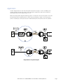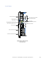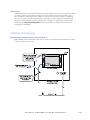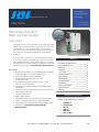
1
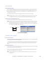
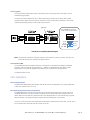
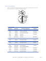
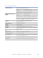
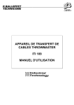
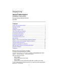
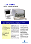
The leader in rugged fiber optic technology. RLH Industries, Inc. Unconditional Lifetime Warranty USER GUIDE U-066 2014A-0205 RLH Single Channel T1 Fiber Link Card System Description The Single Channel T1 Fiber Link Card converts electrical/copper T1(DS1) signals and transport them over optical fiber. The system can operate from T1 span power (60mA) or local 24/48VDC power. It has LED status and alarm output indicators for system monitoring, and is temperature hardened for use in extreme conditions. All of the products in the RLH T1 Fiber Link family are designed for the utmost quality and reliability. Typical applications include high voltage GPR isolation, utility, wireless backhaul, and military communications. RLH single channel T1 systems are made in the USA and are covered by our Unconditional Lifetime Warranty. Key Features RLH Single Channel T1 Fiber Link Card Contents Description and Key Features ____________1 General Safety Practices _________________2 Application __________________________3 Installation __________________________5 Connections _________________________8 Powering the System ____________________8 Switch Settings ________________________9 LED Indicators _______________________10 NIU Compatibility ____________________12 Specifications ________________________13 Ordering Information _________________14 Technical Support ____________________15 Warranty __________________________15 • Single-mode (up to 60km/37mi.) or Multimode (2km/1.2mi.) fiber systems with either ST or SC fiber connector types. • Dual power capable, line or local 24/48VDC. • Simplex 60mA line powering from the T1 span or HDSL NIU/RT unit. • Environmentally hardened to operate in -40°F to +158°F (-40°C to +70°C) environments. • Compatible with 2 Channel DIN/Card and the Single Channel DIN modules. • The same unit may be used at either end of the fiber system, simplifying spares and ordering. • Loopback testing features. • B8ZS or AMI compatible. • NC/NO alarm contact for remote monitoring of system health. The RLH Single Channel T1 Fiber Link Card System is • DIN rail or wall mountable compact modules are available. compliant with the following industry standards: • Can be used within or beyond customer premise environments. • Covered by our Unconditional Lifetime Warranty. • Made in the USA Compliance Information • • • • • • FCC PART-15 FCC PART-68B GR-1089 IEEE-487 IEEE-1590 Motorola R56 RLH Industries, Inc. • Tel. 866-DO-FIBER • Fax 714 532-1885 • www.fiberopticlink.com Page 1 General safety practices The equipment discussed in this document may require tools designed for the purpose being described. RLH recommends that service personnel be familiar with the correct handling and use of any installation equipment used, and follow all safety precautions including the use of protective personal equipment as required. Caution - Severe Shock Hazard • Never install during a lightning storm or where unsafe high voltages are present. • Active T1 lines carry high DC voltages up to 130V. Use caution when handling T1 wiring. • Active HDSL lines carry high DC voltages up to 210V. Use caution when handling HDSL wiring. Warning The intra-building port(s) of the equipment or subassembly is suitable for connection to intrabuilding or unexposed wiring or cabling only. The intra-building port(s) of the equipment MUST NOT be metallically connected to interfaces that connect to the OSP or its wiring. These interfaces are designed for use as intra-building interfaces only (Type 4 ports as described in GR-1089-CORE, Issue 4) and require isolation from the exposed OSP cabling. The addition of Primary Protectors is not sufficient protection in order to connect these interfaces metallically to OSP wiring. Special handling requirements Be careful when handling electronic components This card utilizes circuitry that can be damaged by static electricity. When transporting the card, carry it in an ESD safe container such as the antistatic bag provided with the card. There are no user serviceable parts on the card. Do not open or remove the housing or insert tools or other objects into any openings except to access switches or where otherwise intended. Doing so may permanently damage the card. Guidelines for handling terminated fiber cable • Do not bend fiber cable sharply. Use gradual and smooth bends to avoid damaging glass fiber. • Keep dust caps on fiber optic connectors at all times when disconnected. • Do not remove dust caps from unused fiber. • Keep fiber ends and fiber connectors clean and free from dust, dirt and debris. Contamination will cause signal loss. • Do not touch fiber ends. • Store excess fiber on housing spools or fiber spools at site RLH Industries, Inc. • Tel. 866-DO-FIBER • Fax 714 532-1885 • www.fiberopticlink.com Page 2 Application The RLH Single Channel T1 Fiber Link Card system transports the copper T1 line at 1.544Mbps, and optically transmits over fiber optic cable to the module at the opposite end, which then converts the optical signals back into the original copper T1 line. Below are sample system diagrams illustrating typical T1 connections to and from the system. On the CO (Central Office) side, the Single Channel T1 system may be powered by a single T1 line carrying span power, or optionally by a local power source. The SUB side requires a local power source for operation. Single Channel T1 System Diagram RLH Industries, Inc. • Tel. 866-DO-FIBER • Fax 714 532-1885 • www.fiberopticlink.com Page 3 Front Panel Fiber Optic Connectors Fiber Optic Receive Frame Valid & Frame Alarm Indicator Remote Channel Alarm Indicator Receive BPV (Bipolar Violation) detection DS1 signal detection and Receive AIS (Alarm Indication Signal) detection Power Indicator T1 Line Connector Alarm Connection Terminal Local Power Connection Terminal Single Channel T1 Fiber Link Card Front Panel Layout RLH Industries, Inc. • Tel. 866-DO-FIBER • Fax 714 532-1885 • www.fiberopticlink.com Page 4 Installation Prior to installation: • • • • Check for shipping damage Check the contents to ensure correct model and fiber type Have a clean, dry installation environment ready Ensure that the fiber type at the site matches the system type If damage is discovered file a claim immediately with the carrier, then contact RLH customer service. Required for installation: • • • • 24-56VDC (60mA@24VDC maximum) line or local power source at each side of the system. Suitable RLH Fiber Link Card housing Active T1 line Multimeter You will need a T1 analyzer such as a T-BERD and a multimeter Be familiar with the test settings. Some analyzers have line power and multimeter capability. For installation where no T1 signal is available, the analyzer must be capable of generating a T1 signal. Required power sources if installing before T1 service is available at the site You will need to power the system to test it. Use a separate power source for powering the CO and Sub side card. A battery may be used. 24 - 56VDC AC Volts CO Side 24 - 56VDC AC Volts BATT OK + – Multimeter Power Source Sub Side BATT OK + – Multimeter Power Source Use 22~24AWG solid wire for power supply connections. Refer to the power supply connection and use information for fuse or circuit breaker requirements. Use caution when handling copper wiring. Power connections may carry high voltages. Fuses must be installed within a finger safe housing to prevent electric shock from accidental contact or during fuse replacement. RLH Industries, Inc. • Tel. 866-DO-FIBER • Fax 714 532-1885 • www.fiberopticlink.com Page 5 Line Powering The Single Channel T1 card can be line powered via 60mA simplex current on the T1 line. When an HDSL or T1 NIU is placed at the CO side of the Fiber Link it must provide span-through line power to the T1 fiber interface card. When line power is available, no external or local power is required to operate the fiber card. An active T1 line with 60mA line power connected to the fiber interface card should typically measure 22-30VDC between transmit and receive pairs. If voltage is not present verify the NIU model number using the NIU Compatibility Chart listed in this document, or contact RLH to ensure spanthrough power compatibility. Installing card housing Mount housing in equipment rack or attach to backboard. When installing an RLH card housing, leave room for the door to open and provide enough slack in wiring and fiber to allow for card access. RLH Industries, Inc. • Tel. 866-DO-FIBER • Fax 714 532-1885 • www.fiberopticlink.com Page 6 Note card orientation in housing during installation Handle card by edges. Install in slot 1 or next available card slot. Install card into housing before connecting fiber or copper wiring. Copper wiring requirements Copper wiring to the T1 cards The connectors on the T1 cards are designed for specific wire sizes and mechanical connections at the terminals. • • • Use 22~24AWG solid copper wire Stripping length: 8mm Connector tightening torque: 0.5~0.6 Nm. Do not over-tighten screw down wire terminals. RLH Industries, Inc. • Tel. 866-DO-FIBER • Fax 714 532-1885 • www.fiberopticlink.com Page 7 Connections Connect Fiber Optic Cable The T1 cards are equipped with two optical connectors. Connect the fiber to the Transmit and Receive fiber connectors. The transmit port is marked TX, and the receiver port is marked RX. Verify that the TX fiber at one card is connected to the RX port on the opposite end. The system will not operate if TX is connected to TX or RX to RX. Fiber cables should be routed loosely avoiding tight bends to prevent excessive optical loss. Note: The Single Channel T1 Fiber Link cards are compatible with the Single Channel T1 Fiber Link DIN units. Refer to the DIN mount user guides for information related to the DIN mount modules. Connect Copper T1 Send and Receive pairs The T1 pairs from the Telco connect to the RJ-48C connector on the face of the card. Note: At the CO side, the Single Channel T1 modules are designed to operate on standard T1 lines that are current limited at 60mA. Open circuit voltage on T1 lines can vary from 30V to 130V across send and receive pairs depending on the number of repeaters in the line. However, voltage across the module when operating will be 30VDC or less. RJ-48C Port PIN 1 PIN 8 1 Receive (Ring) 5 Transmit (Tip) 2 Receive (Tip) 6 NC 3 NC 7 NC 4 Transmit (Ring) 8 NC RJ Connector Pinout Diagram Powering the System Powering at the CO end Typically, the CO side module is span powered by a single 60mA simplex current sources derived from the T1 Telco Span Transmit and Receive copper pairs. The CO side module may also be powered externally by connecting a 24-56VDC 60mA power source to the power terminal on the unit. The 1 Channel T1 Cards are polarity insensitive to the DC input power source. Powering at the SUB end To local power, connect a 24-56VDC 60mA power source to the power terminal on the unit. The cards are polarity insensitive to the DC input power source. To span power the SUB side module you must have a minimum of one 60mA simplex current source on the T1 Send and Receive pairs on a working circuit. Note: The CO and SUB units must be powered by separate isolated power sources to maintain high voltage isolation. RLH Industries, Inc. • Tel. 866-DO-FIBER • Fax 714 532-1885 • www.fiberopticlink.com Page 8 T1 Surge Protection Thermistors, and Sidactors limit transients appearing between the Tip and Ring of each pair. Transients appearing at the power terminals or between input and output pairs are limited by PTC thermistors and a metal oxide varistor. T1 Alarm Contact The Single Channel T1 System alarm contact allows you to monitor the health of your T1 Fiber Link system. If any of the below faults are present the alarm contact will revert to its normal state: • BPV - Bi-polar Violations • AIS - All One’s Condition • FRM Alarm - Fiber Frame Loss • PWR - DC Power Loss When all of the above conditions are OK the contact will change from its resting state to indicate that the system is running and healthy. Switch Settings The DIP switch is located on the top surface of the card. You may need to pull the card slightly out of the card housing to gain sufficient access to the switch. B8ZS or AMI Encoding The AMI/B8ZS DIP switch is used to establish the selection of B8ZS (bit 8 zero substitution) or AMI (alternate mark inversion) line encoding for the T1 input. Remote Loopback The remote (RLOOP) loopback DIP switch is provided to allow for remote loop back of the copper T1 line for trouble shooting purposes. The loop back function begins at the T1 receive twisted pair, through the T1 LIU (Line Interface Unit), and then back out the T1 transmit twisted pair. Normal operating position is OFF for All switch positions. • Turn on RLOOP switch to check copper wire connection Signal Loop SUB Side Module (Local Side) CO Side Module (Remote Side) ON T-1 TEST EQUIPMENT 1 2 3 4 5 6 LLOOP RLOOP ON - AMI OFF - B8ZS TX IN RX OUT Fiber 1 2 3 4 5 6 ON 1 2 3 4 5 6 TX RX RX TX ON NOT USED LBO-15 LBO-7.5 RLOOP (Remote Loopback) Switch Diagram RLH Industries, Inc. • Tel. 866-DO-FIBER • Fax 714 532-1885 • www.fiberopticlink.com Page 9 Local Loopback The local (LLOOP) loopback DIP switch is provided to allow for local loop back of the fiber T1 line for troubleshooting purposes. The loop back function begins with the T1 fiber transmit data coming from the remote side module, through the fiber cable to the local receiver, then back out from the local fiber transmitter to the remote side. Normal operating position is OFF for All switch positions. Signal Loop • Turn on LLOOP switch to have fiber loop back or to check for fiber connection. ON 1 2 3 4 5 6 LLOOP RLOOP ON - AMI OFF - B8ZS NOT USED LBO-15 LBO-7.5 LLOOP (Local Loopback) Switch Diagram Note: The LEDs will indicate the matching conditions upon detection of errors or alarms. The LEDs will remain ON until the error condition has been removed. Line Build Out (LBO) The Line Build Out switch simulates cable loss of the signal for compatibility with different installation scenarios. There are switches corresponding to -7.5dB and -15dB attenuation level. Select a level appropriate for your particular application by setting one of the switches to the ON position. The default position is OFF. LED Indicators Remote Channel Alarm The REM CH ALARM (yellow) LED indicates that the far end unit has detected a loss of fiber signal, BPV, or AIS fault condition from the T1 LIU. Fiber Optic Receive Frame Valid / Frame Alarm The FIBR FRM (green) LED will remain ON as long as the fiber optic receiver stays in frame with the far end Single Channel T1 card. Only if there is a problem with the receive frame does the green LED turn yellow. When this LED does turn yellow then both of the Single Channel T1 end units will begin a system resynchronization. This resynchronization requires about ten milliseconds to accomplish. The LED is continuously ON if the local receiver cannot detect receive frame from the fiber. The loss of the far end receive frame will cause this LED to blink on and off. RLH Industries, Inc. • Tel. 866-DO-FIBER • Fax 714 532-1885 • www.fiberopticlink.com Page 10 Power Indicator The PWR (green) LED will be ON when acceptable power is detected at the card. Span power or a local power source can provide enough power for the system. When the power LED is off, the system is not detecting enough power to operate. T1 Activity The ACTIVE (green) LED will be ON when a valid DS1 signal is detected at the RJ connector. Alarm Indication Signal The AIS alarm (red) LED will be ON whenever a series of unframed all-ones are received at the input of the T1 LIU. This alarm indicates that equipment down the line from the T1 receiver has detected a loss of signal and is transmitting an unframed all-ones alarm signal. Bipolar Violation The BPV alarm (yellow) LED will be looking for any bipolar violations at the receive T1 LIU. The LED will remain ON for a visible period per detected event. BPV detection can indicate loss of line integrity at the receiver. Note: If the transmitting equipment is using encoded B8ZS, and the card is configured for AMI, the channel BPV alarm LED will turn ON. Single Channel T1 LED Indicators Note Bi-color LEDs RLH Industries, Inc. • Tel. 866-DO-FIBER • Fax 714 532-1885 • www.fiberopticlink.com Page 11 NIU Compatibility Check for compatible NIU systems that supply Span Through-Power to the Single Channel T1 Fiber Link cards. Contact RLH for T1 compatibility with systems not listed. NIU Part Number NIU Card HDSL/T1 Span Through Power NIU Compatibility Chart Manufacturer Part Number Description and Material ID CLEI Code HDSL1 Adtran 1246026L4 T200 HTU-R (VZ# 594993) T1L2C8J8AA Adtran 1246026L5 T200 HTU-R (BST# 98001580) T1L3KD5AAA Adtran 1245024L1 T400 HTU-R T1L2C8J8AA Adtran 1247026L1 T200 HTU-R, ADC SPX-HLXRD11 T400 HLXR SND1FJRAAA HDSL2 Adtran 1223024L1 H2TU-R (VZ# 11018736) T1L6VR8B_ _ HDSL4 Adtran 1223424L1 H4TU-R (VZ# 11018731) T1L6EYHB_ _ Repeated T1 Adtran 1181315L1-5B T1 NIU, Total Access T1L3PU0A Hyperedge 520-10-SWI3 T200 T1 NIU (BST# 300058336) Westell DNI5760LNI3 T1 NIU (VZ# NCIUV9A) NCIUV9A4AA Westell A90-3128-70 T1 NIU (VZ# T1L3P96) T1L3P96CAA Westell A90-3115-31 T1 NIU (VZ# T1S1AEF) T1S1AEFAAA RLH Industries, Inc. • Tel. 866-DO-FIBER • Fax 714 532-1885 • www.fiberopticlink.com Page 12 General Specifications Transmission method Amplitude modulated light via two optical fibers Maximum Fiber Attenuation / Distance Multimode: 850nm (Tx level: -16dB ± 1dB) Single-mode: 1310nm (Tx level: -23dB ± 1dB) Single-mode Long Haul: 1310nm (Tx level: -8dB ± 2dB) Multimode: 10dB / 1.2 miles (2 km) Single-mode: 8dB / 9 miles (15 km) Single-mode Long Haul: 26dB* / 37 mi. (60 km), *min. required loss -8dB *Note: Distances equated using industry standard fiber and connector attenuation of 3dB/Km. Fiber condition, splices and connectors may affect actual range. Fiber Type (ST or SC connectors) Multimode: 62.5/125µm, 50/125µm Single-mode: 8-9/125µm Temperature Limits -40°F to +158°F (-40°C to +70°C) Humidity 95% non-condensing Dimensions RLH Standard Fiber Link Card Form Factor L7” x W4”x H1.2” Mounting Installed into any RLH Fiber Link Card Housing. Rack, DIN mount and wall mount housings are available. BER <10-9 Surge Protection Fuses, thyristors, PTC thermistors, zeners, and MOVs Local Power Requirement 24-56 VDC, 60mA maximum Powering Method 60mA line power simplexed on Send and Receive pairs, or an isolated DC power source connected to power input terminals. Power Connector Non-polarity sensitive local power input via removable screw down terminal block Compatibility Compatible with RLH 1 & 2 Channel Fiber Link Card and DIN systems. RLH Industries, Inc. • Tel. 866-DO-FIBER • Fax 714 532-1885 • www.fiberopticlink.com Page 13 Dimensions 1.24 in. (31mm) 3.93 in. (100mm) 6.94 in. (176mm) Ordering Information Single Channel T1 Fiber Link Card System Part Number Description Distance Fiber Part Number Multimode ST Single Channel T1 (CO/SUB) 2km/ 1.2 mi 62.5/50µm 1T4-02-1 Multimode SC Single Channel T1 (CO/SUB) 2km/ 1.2 mi 62.5/50µm 1T4-01-1 Single Channel T1 (CO/SUB) 15km/ 9 mi 8~9µm 1T4-20-1 Single Channel T1 (CO/SUB) 60km/ 37mi 8~9µm 1T4-21-1 Single Channel T1 (CO/SUB) 15km/ 9 mi 8~9µm 1T4-10-1 Single Channel T1 (CO/SUB) 60km/ 37mi 8~9µm 1T4-11-1 Single-mode ST Single-mode SC A complete system requires a card on both ends of fiber. Plug and play compatible with RLH 1 & 2 Channel Fiber Link Card and DIN systems. Please contact your RLH sales representative for pricing and delivery information. RLH Industries, Inc. • Tel. 866-DO-FIBER • Fax 714 532-1885 • www.fiberopticlink.com Page 14 Warranty RLH is recognized throughout the U.S. and offers the only UNCONDITIONAL LIFETIME WARRANTY in the telecommunications industry. We are very proud of our warranty which simply states that our transmission products are guaranteed to be free of defects in material and workmanship for the LIFE OF THE PRODUCT. Look for the warranty badge. We can offer this warranty because: • We believe our customers shouldn't have to incur additional costs due to failure or damage. • We engineer and manufacture our Fiber Optic Links in the USA, with total confidence in our quality. • We understand how safety and reliability impact the total cost of ownership. • We know that customer support extends beyond the initial sale, so we stand behind our products. RLH will replace these products or components that fail FOR ANY REASON. This warranty is UNCONDITIONAL and valid even when products have been abused or mishandled, when unauthorized repairs have been attempted or performed, or as a result of a natural disaster. Compare this warranty to our competitors and it becomes clear how RLH products will reduce your costs and simplify your maintenance activities. To make a warranty claim, or schedule repair or replacement of your RLH product, contact us for an RMA number. You will be promptly assisted by one of our warranty specialists. An RMA number is required before we can receive any items. Technical Support Normal technical support: (714) 532-1672 (Mon - Fri 6am - 6pm PST) Toll Free 1-800-877-1672 Toll Free 1-866-DO-FIBER Email: [email protected] 24/7 technical support: Toll Free 1-855-RLH-24X7 (Outside normal business hours) Toll Free 1-855-754-2497 Contact Information Corporate Headquarters: RLH Industries, Inc. 936 N. Main Street Orange, CA 92867 USA Phone: (714) 532-1672 Toll Free 1-800-877-1672 Toll Free 1-866-DO-FIBER Fax: (714) 532-1885 Email: [email protected] Web site: www.fiberopticlink.com RLH Industries, Inc. • Tel. 866-DO-FIBER • Fax 714 532-1885 • www.fiberopticlink.com Page 15 RLH Industries, Inc. 6/$0/%*5*0/"--*'&5*.&8"33"/5: RLH INDUSTRIES, INC. FIBER OPTIC LINK products are warranted to be free of defects in materials and workmanship for the LIFE OF THE PRODUCT. This lifetime warranty is effective for RLH fiber optic link products sold since the date RLH was founded, February 2, 1988, with the exception of fiber cable products which are warranted to free of defects in manufacturing, and batteries which carry a 10-year unconditional replacement warranty. RLH Industries, Inc. will repair or replace these products that fail FOR ANY REASON, provided the defective part is returned to RLH freight prepaid. This warranty is UNCONDITIONAL and valid even when products have been abused or mishandled, when unauthorized repairs have been attempted or performed, or damaged as a result of a natural disaster. Authorized by: J. RANDALL MEARS, Vice President, Engineering ."%&*/64" RLH Industries, Inc. 936 N. Main Street, Orange, CA 92867 USA T: (714) 532-1672 F: (714) 532-1885 Please contact your RLH sales representative for pricing and delivery information. Specifications subject to change without notice. RLH Industries, Inc. • Tel. 866-DO-FIBER • Fax 714 532-1885 • www.fiberopticlink.com Page 16