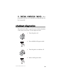
1
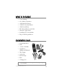
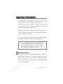
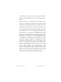
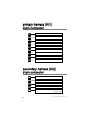
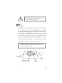
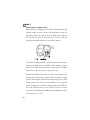
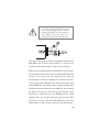
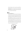
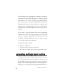
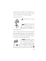
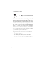
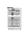
Model 369D
➤Owner’s/Installation
Guide
limited lifetime consumer warranty
For a period of one calendar year from the date of purchase of this auto-security device,
Directed Electronics, Inc. promises to the ORIGINAL PURCHASER to repair or replace
(with a comparable reconditioned model), free of cost, any electronic control module
which proves to be defective in workmanship or material under normal use, SO LONG
AS THE SYSTEM WAS SOLD, INSTALLED, AND SERVICED BY A PROFESSIONAL AUTO INSTALLER, AND REMAINS IN THE CAR IN WHICH THE SYSTEM WAS ORIGINALLY INSTALLED. If warranty service is necessary you must have
a clear copy of your sales receipt containing all of the information shown on the following page.
After the first calendar year, from the date of purchase of this auto-security device,
Directed Electronics, Inc., promises to the ORIGINAL PURCHASER to repair or replace
(with a comparable reconditioned model) any electronic control module which proves to
be defective in workmanship or material under normal use FOR A CHARGE OF $45.00,
SO LONG AS THE SYSTEM WAS SOLD, INSTALLED, AND SERVICED BY A
PROFESSIONAL AUTO INSTALLER, AND REMAINS IN THE CAR IN WHICH
THE SYSTEM WAS ORIGINALLY INSTALLED. If warranty service is necessary you
must have a clear copy of your sales receipt containing all of the information shown on
the following page.
This warranty contains the entire agreement relating to warranty and supersedes all previous and contemporaneous representations or understandings, whether written or oral.
IN ANY EVENT, Directed Electronics, Inc. IS NOT LIABLE FOR THE THEFT OF
THE VEHICLE AND/OR ITS CONTENTS.
This warranty is void if the product has been damaged by accident, unreasonable use,
neglect, improper service or other causes not arising out of defects in materials or construction. This warranty is nontransferable and does not apply to any unit that has been
modified or used in a manner contrary to its intended purpose and does not cover batteries. The unit in question must be returned to the manufacturer, postage prepaid. This
warranty does not cover labor costs for the removal, diagnosis, troubleshooting or reinstallation of the unit. For service on an out-of-warranty product a flat rate fee by model is
charged. Contact your authorized dealer to obtain the service charge for your unit.
These systems are a deterrent against possible theft. Directed Electronics, Inc. is not offering a guarantee or insuring against the theft of the automobile or its contents and disclaims any liability for the theft of the vehicle and/or its contents. Directed Electronics
does not authorize any person to create for it any other obligation or liability in connection with this security system.
© 2003 directed electronics, inc.
i
TO THE MAXIMUM EXTENT ALLOWED BY LAW, ANY AND ALL WARRANTIES ARE EXCLUDED BY THE MANUFACTURER AND EACH ENTITY
PARTICIPATING IN THE STREAM OF COMMERCE THEREWITH. THIS
EXCLUSION INCLUDES BUT IS NOT LIMITED TO THE EXCLUSION OF ANY
AND ALL WARRANTY OF MERCHANTABILITY AND/OR ANY AND ALL WARRANTY OF FITNESS FOR A PARTICULAR PURPOSE AND/OR ANY AND ALL
WARRANTY OF NON-INFRINGEMENT OF PATENTS, IN THE UNITED
STATES OF AMERICA AND/OR ABROAD. NEITHER THE MANUFACTURER
OR ANY ENTITIES CONNECTED THEREWITH SHALL BE RESPONSIBLE OR
LIABLE FOR ANY DAMAGES WHATSOEVER, INCLUDING BUT NOT LIMITED TO ANY CONSEQUENTIAL DAMAGES, INCIDENTAL DAMAGES, TOWING, REPAIR, REPLACEMENT, DAMAGES FOR LOSS OF TIME, LOSS OF
EARNINGS, COMMERCIAL LOSS, LOSS OF ECONOMIC OPPORTUNITY
AND THE LIKE. NOTWITHSTANDING THE ABOVE, MANUFACTURER
DOES OFFER A LIMITED WARRANTY TO REPLACE OR REPAIR THE CONTROL MODULE AS DESCRIBED ABOVE. Some states do not allow limitations on
how long an implied warranty will last or the exclusion or limitation of incidental or consequential damages. This warranty gives you specific legal rights, and you may also have
other rights which vary from state to state.
IMPORTANT NOTE:
This product warranty is automatically void if its date code or serial number is defaced,
missing, or altered. This warranty will not be valid unless you have completed the warranty card and mailed it to Directed Electronics, Inc. within 10 days after purchase to the
address listed on the warranty registration card.
Make sure you have all of the following information from your dealer:
A clear copy of the sales receipt, showing the following:
➤
➤
➤
➤
➤
➤
➤
➤
➤
ii
Date of purchase
Your full name and address
Authorized dealer's company name and address
Type of remote start/keyless entry installed
Year, make, model and color of the automobile
Automobile license number
Vehicle identification number
All security options installed on automobile
Installation receipts
© 2003 directed electronics, inc.
table of contents
limited lifetime consumer warranty . . . . . . . . . . . . . . . . . . . . . . . . . . . . . . . . . . . . . . . . i
what is included . . . . . . . . . . . . . . . . . . . . . . . . . . . . . . . . . . . . . . . . . . . . . . . . . . . . . . 3
installation tools . . . . . . . . . . . . . . . . . . . . . . . . . . . . . . . . . . . . . . . . . . . . . . . . . . . . . . 3
important information . . . . . . . . . . . . . . . . . . . . . . . . . . . . . . . . . . . . . . . . . . . . . . . . . 4
system maintenance . . . . . . . . . . . . . . . . . . . . . . . . . . . . . . . . . . . . . . . . . . . . . . 4
your warranty . . . . . . . . . . . . . . . . . . . . . . . . . . . . . . . . . . . . . . . . . . . . . . . . . . . 5
fcc/id notice . . . . . . . . . . . . . . . . . . . . . . . . . . . . . . . . . . . . . . . . . . . . . . . . . . . . 5
warning! safety first . . . . . . . . . . . . . . . . . . . . . . . . . . . . . . . . . . . . . . . . . . . . . . . . . . . 5
primary harness (H/1), 9-pin connector . . . . . . . . . . . . . . . . . . . . . . . . . . . . . . . . . . . 8
secondary harness (H/2),6-pin connector . . . . . . . . . . . . . . . . . . . . . . . . . . . . . . . . . . . 8
relay satellite ribbon harness (H/3), 4-pin connector . . . . . . . . . . . . . . . . . . . . . . . . . . 9
relay satellite thick gauge wires . . . . . . . . . . . . . . . . . . . . . . . . . . . . . . . . . . . . . . . . . . . 9
installation . . . . . . . . . . . . . . . . . . . . . . . . . . . . . . . . . . . . . . . . . . . . . . . . . . . . . . . . . 10
step 1 . . . . . . . . . . . . . . . . . . . . . . . . . . . . . . . . . . . . . . . . . . . . . . . . . . . . . . . . 11
step 2 . . . . . . . . . . . . . . . . . . . . . . . . . . . . . . . . . . . . . . . . . . . . . . . . . . . . . . . . 12
step 3 . . . . . . . . . . . . . . . . . . . . . . . . . . . . . . . . . . . . . . . . . . . . . . . . . . . . . . . . 14
step 4 . . . . . . . . . . . . . . . . . . . . . . . . . . . . . . . . . . . . . . . . . . . . . . . . . . . . . . . . 15
step 5 . . . . . . . . . . . . . . . . . . . . . . . . . . . . . . . . . . . . . . . . . . . . . . . . . . . . . . . . 19
step 6 . . . . . . . . . . . . . . . . . . . . . . . . . . . . . . . . . . . . . . . . . . . . . . . . . . . . . . . . 20
step 7 . . . . . . . . . . . . . . . . . . . . . . . . . . . . . . . . . . . . . . . . . . . . . . . . . . . . . . . . 23
step 8 . . . . . . . . . . . . . . . . . . . . . . . . . . . . . . . . . . . . . . . . . . . . . . . . . . . . . . . . 26
step 9 . . . . . . . . . . . . . . . . . . . . . . . . . . . . . . . . . . . . . . . . . . . . . . . . . . . . . . . . 27
step 10 . . . . . . . . . . . . . . . . . . . . . . . . . . . . . . . . . . . . . . . . . . . . . . . . . . . . . . . 28
step 11 . . . . . . . . . . . . . . . . . . . . . . . . . . . . . . . . . . . . . . . . . . . . . . . . . . . . . . . 29
transmitter/receiver learn routine . . . . . . . . . . . . . . . . . . . . . . . . . . . . . . . . . . . . . . . . 30
operating settings learn routine . . . . . . . . . . . . . . . . . . . . . . . . . . . . . . . . . . . . . . . . . 32
features menu . . . . . . . . . . . . . . . . . . . . . . . . . . . . . . . . . . . . . . . . . . . . . . . . . . . . . . 35
feature descriptions . . . . . . . . . . . . . . . . . . . . . . . . . . . . . . . . . . . . . . . . . . . . . . . . . . 36
shutdown diagnostics . . . . . . . . . . . . . . . . . . . . . . . . . . . . . . . . . . . . . . . . . . . . . . . . . 39
transmitter functions . . . . . . . . . . . . . . . . . . . . . . . . . . . . . . . . . . . . . . . . . . . . . . . . . 40
standard configuration . . . . . . . . . . . . . . . . . . . . . . . . . . . . . . . . . . . . . . . . . . . 41
using your system . . . . . . . . . . . . . . . . . . . . . . . . . . . . . . . . . . . . . . . . . . . . . . . . . . . 42
warning! safety first . . . . . . . . . . . . . . . . . . . . . . . . . . . . . . . . . . . . . . . . . . . . . . 42
locking . . . . . . . . . . . . . . . . . . . . . . . . . . . . . . . . . . . . . . . . . . . . . . . . . . . . . . . 44
unlocking . . . . . . . . . . . . . . . . . . . . . . . . . . . . . . . . . . . . . . . . . . . . . . . . . . . . . 44
ignition controlled door locks . . . . . . . . . . . . . . . . . . . . . . . . . . . . . . . . . . . . . . 44
remote start. . . . . . . . . . . . . . . . . . . . . . . . . . . . . . . . . . . . . . . . . . . . . . . . . . . . 45
short-run/turbo . . . . . . . . . . . . . . . . . . . . . . . . . . . . . . . . . . . . . . . . . . . . . . . . . 46
© 2003 directed electronics, inc.
1
timer mode . . . . . . . . . . . . . . . . . . . . . . . . . . . . . . . . . . . . . . . . . . . . . . . . . . . . 47
valet take-over . . . . . . . . . . . . . . . . . . . . . . . . . . . . . . . . . . . . . . . . . . . . . . . . . . 48
programming options . . . . . . . . . . . . . . . . . . . . . . . . . . . . . . . . . . . . . . . . . . . . . . . . 49
troubleshooting . . . . . . . . . . . . . . . . . . . . . . . . . . . . . . . . . . . . . . . . . . . . . . . . . . . . . 49
glossary of terms . . . . . . . . . . . . . . . . . . . . . . . . . . . . . . . . . . . . . . . . . . . . . . . . . . . . 53
wiring quick reference guide . . . . . . . . . . . . . . . . . . . . . . . . . . . . . . . . . . . . . . . . . . . 54
notes . . . . . . . . . . . . . . . . . . . . . . . . . . . . . . . . . . . . . . . . . . . . . . . . . . . . . . . . . . . . . 55
quick reference guide . . . . . . . . . . . . . . . . . . . . . . . . . . . . . . . . . . . . . . . . . . . . . . . . . 45
2
© 2003 directed electronics, inc.
what is included
➤
Control Module
➤
One 3-Button Transmitter
➤
9-Pin Main H/1 Harness
➤
5-Pin H/2 Secondary Harness
➤
4-Pin External Relay
➤
HF+ External Receiver and Cable
➤
Shutdown Toggle Switch
➤
Dual-Relay Door Lock Module
➤
Plug-in Valet/Program Button
installation tools
➤
Digital Multi-Meter
➤
Drill
➤
9
➤
Screwdrivers
/32 and 5/16 Drill Bits
(Phillips and Flathead)
➤
Wire Stripper
➤
Solder Iron
➤
Electrical Tape
➤
Pliers
➤
Crimping Tool
note: The installation tools required will vary depending
on your vehicle.
© 2003 directed electronics, inc.
3
important information
Congratulations on the purchase of your remote start keyless
entry system. This system will allow convenient access to your
vehicle with the push of a button, as well as remote start and
other optional features. Properly installed, this system will
provide years of trouble-free operation.
Please take the time to carefully read this User’s Guide in its
entirety and watch the Rattler Do-It-Yourself Installation Video
prior to installing your system.
You can print additional or replacement copies of this manual by
accessing the Directed web site at www.diyrattler.com.
important! If you are not comfortable working with electronics or unfamiliar with the tools required, please contact your local dealer for advice or ask to have the remote
start professionally installed to avoid costly damages.
Failure to properly install the remote starter may result in
property damage, personal injury, or both.
➜ system maintenance
The system requires no specific maintenance. Your remote is
powered by a miniature 3-volt lithium battery that will last
approximately one year under normal use. When the battery
begins to weaken, operating range will be reduced and the LED
on the remote will dim.
4
© 2003 directed electronics, inc.
➜ your warranty
Your warranty registration must be completely filled out and
returned within 10 days of purchase. Your product warranty
will not be validated if your warranty registration is not returned.
Please note that it is necessary to keep your proof of purchase.
➜ fcc/id notice
This device complies with Part 15 of FCC rules. Operation is
subject to the following conditions: (1) This device may not
cause harmful interference, and (2) This device must accept any
interference received, including interference that may cause
undesirable operation.
Changes or modifications not expressly approved by the party
responsible for compliance could void the user's authority to
operate this device.
warning! safety first
The following safety warnings must be observed at all times:
➤
When properly installed, this system can start the vehicle via
a command signal from the remote control transmitter.
Therefore, never operate the system in an area that does not
have adequate ventilation. The following precautions are the
sole responsibility of the user; however, the following recommendations should be made to all users of this system:
© 2003 directed electronics, inc.
5
1. Never operate the system in an enclosed or partially
enclosed area without ventilation (such as a garage).
2. When parking in an enclosed or partially enclosed area
or when having the vehicle serviced, the remote start
system must be disabled using the toggle switch.
3. It is the user's sole responsibility to properly handle and
keep out of reach from children all remote control transmitters to assure that the system does not unintentionally remote start the vehicle.
4. THE
USER
MUST
INSTALL
A
CARBON
MONOXIDE DETECTOR IN OR ABOUT THE
LIVING AREA ADJACENT TO THE VEHICLE.
ALL DOORS LEADING FROM ADJACENT
LIVING AREAS TO THE ENCLOSED OR
PARTIALLY ENCLOSED VEHICLE STORAGE
AREA MUST AT ALL TIMES REMAIN CLOSED.
➤
Use of this product in a manner contrary to its intended
mode of operation may result in property damage, personal
injury, or death. Except when performing the Safety Check
outlined in this user’s guide, (1) Never remotely start the
vehicle with the vehicle in gear, and (2) Never remotely start
the vehicle with the keys in the ignition. The user will be
responsible for having the neutral safety feature of the vehicle
periodically checked, wherein the vehicle must not remotely
start while the car is in gear. This testing should be performed
by an authorized Directed dealer in accordance with the
Safety Check outlined in this product installation guide. If
6
© 2003 directed electronics, inc.
the vehicle starts in gear, cease remote start operation immediately and consult with the Dealer to fix the problem immediately.
➤
After the remote start module has been installed, test the
remote start module in accordance with the Safety Check
outlined in this installation guide. If the vehicle starts when
performing the Neutral Safety Shutdown Circuit test, the
remote start unit has not been properly installed. The remote
start module must be removed or properly reinstalled so that
the vehicle does not start in gear. OPERATION OF THE
REMOTE START MODULE IF THE VEHICLE STARTS
IN GEAR IS CONTRARY TO ITS INTENDED MODE
OF OPERATION. OPERATING THE REMOTE START
SYSTEM
UNDER THESE
CONDITIONS
MAY
RESULT IN PROPERTY DAMAGE OR PERSONAL
INJURY. IMMEDIATELY CEASE THE USE OF THE
UNIT AND REPAIR OR DISCONNECT THE
INSTALLED REMOTE START MODULE. DIRECTED
WILL NOT BE HELD RESPONSIBLE OR PAY FOR
INSTALLATION OR REINSTALLATION COSTS.
© 2003 directed electronics, inc.
© 2002 directed electronics, inc.
primary harness (H/1),
9-pin connector
H1/1
LT. GREEN/BLACK
Factory Alarm Disarm
H1/2
GREEN/WHITE
H1/3
YELLOW
H1/4
WHITE/BLUE
(-) Activation Input
H1/5
GRAY/BLACK
(-) Wait to Start Input
H1/6
WHITE/RED
(+) Activation Input
H1/7
RED/WHITE
Channel 2 (output)
H1/8
BLACK
Ground
H1/9
WHITE
(+/-) Light Flash
Factory Alarm Rearm
Ignition Output (to alarm)
secondary harness (H/2),
6-pin connector
8
H2/1
BLACK/WHITE
(-) Neutral Safety Switch Input
H2/2
VIOLET/WHITE
H2/3
BROWN
H2/4
GRAY
H2/5
BLUE/WHITE
Tachometer Input
(+)Brake Switch Shutdown Wire
(-) Hood Pinswitch Shutdown Wire
(-) 200 mA 2nd Status/Rear
Defogger Output
© 2003 directed electronics, inc.
relay satellite ribbon harness (H/3),
4-pin connector
H3/1
BLUE
H3/2
ORANGE
H3/3
PURPLE
H3/4
PINK
Status Output
Accessory Relay Trigger
Starter Relay Trigger
Ignition Relay Trigger
relay satellite thick gauge wires
H4/1
PINK
H4/2
PURPLE
H4/3
ORANGE
H4/4
RED
H4/5
H4/6
PINK/WHITE
RED
© 2003 directed electronics, inc.
(+) (30A) Output to Ignition Circuit
(+) (30A) Output to Starter Circuit
(+) (30A) Output to Accessory Circuit
(+) (30A) High Current 12V Input
(+) Programmable Output for
Accessory or Ignition
(+) (30A) High Current 12V Input
9
installation
Be sure to read this section thoroughly and view the Rattler DoIt-Yourself Installation Video in its entirety before starting the
installation. Pay special attention to all warnings to prevent
personal injury or damage to your vehicle.
www.diyrattler.com) to get
Visit our 24-hour technical Web site (w
a vehicle-specific wiring guide prior to starting this installation.
If at any time during the installation you are unable to answer
your questions on the Web site, call 1-800-873-1314 for live
technical assistance.
warning! This system is intended for automatic, fuel-injected vehicles only. Installation
in any other vehicle is contrary to its intended use.
warning! On vehicles with air bags or supplemental restraint systems (SRS) you may
notice a bright yellow tube with small wires
in it marked SRS underneath the steering
column near the key cylinder. DO NOT
tamper or unplug these for any reason to
prevent costly damages to your vehicle or
personal injury. Tampering may cause
unintended deployment of airbags.
warning! DO NOT use any testing tool
other than a digital multi-meter to prevent
costly damages to your vehicle. Use of a test
light may cause grounding of sensitive electrical components that can damage the onboard vehicle computer and processors
resulting in substantial cost for replacement.
10
© 2003 directed electronics, inc.
warning! Verify that the vehicle is set to
park and that the parking brake is set
before beginning installation.
➜ step 1
Ground Wire
The BLACK wire on the main 8-pin harness is ground. This
wire should be connected to a clean, paint-free area of metal in
the drivers kick panel area. First strip back a ¾-inch section of
the insulation off the BLACK wire and crimp a ring terminal
(not provided) to that wire. Locate a clean, paint-free metal
surface in the drivers kick panel. Using a self-tapping screw, drill
the screw with the ring terminal to the metal area. Once screwed
down, pull on the wire to ensure a good connection.
note: More problems are attributed to poor ground connections than any other cause. Take extra care to ensure
the ground is clean and secure.
SELF-TAPPING
BOLT OR SCREW
GROUND
WIRE
DIA-591
NOTE: REMOVE ANY PAINT
BELOW RING CONNECTOR
© 2003 directed electronics, inc.
RING
CONNECTOR
11
➜ step 2
Constant Power and Ignition wires
Almost all power and ignition wires can be found behind the key
cylinder under the lower drivers side dash panel. Using the
appropriate hand tools, remove the lower dash panel using care
not to break any parts. If the panel does not come off easily
check for any additional screws you may have missed.
Once the lower dash panel has been removed, locate the ignition
harness at the back of the key cylinder. This is usually a group of
thicker wires. With the ignition harness exposed, use your digital
multi-meter to find your power and ignition wires.
Place the black lead of the meter to a clean metal surface in the
kick panel area and secure it. Put the meter in the DC voltage
position, then take the red lead of the meter and probe one of the
thicker gauge wires. The color and identity of your specific
vehicle wiring can be obtained at www.diyrattler.com. With the
key in the OFF position, test the suspect wire. The constant
power wire will read between 11.00 volts and 13.00 volts regardless if the key is on or off.
12
© 2003 directed electronics, inc.
warning! Before making any connection
to constant battery power make sure that
the two green 30 amp fuses are removed
from the fuse holders on the two thick red
wires. Failure to do so may cause fire or
shorting of sensitive electrical components.
Once the constant power wire has been identified, solder the two
thick RED wires from the control module to it and cover the
connection with electrical tape to ensure a safe connection.
With the meter black lead still in the kick panel, locate the ignition wire harness in the same location. It will test differently than
constant (+)12 volts. Locate the suspected wire using the
www.diyrattler.com Web site and place the red lead of the meter
on the suspected wire. With the key in the off position the meter
will read 0.00 volts. Turn the key to the on position and the meter
should read between 11.00 volts and 13.00 volts. Now watching
the meter, turn the key to the crank position and the voltage
should drop a small amount but not disappear. If the voltage
disappears this is not an ignition wire but an accessory wire. If the
wire meters correctly, solder the thick PINK wire of the relay
satellite pack to it and cover the connection with electrical tape.
© 2003 directed electronics, inc.
13
If the vehicle requires more than one ignition as per the Web site
information follow the same test procedure and solder the thick
PINK/WHITE wire to it and be sure to cover your connection
with electrical tape. If your vehicle requires more than two ignitions, contact Rattler Technical Support.
➜ step 3
Accessory and Starter wires
The starter and accessory wires will be located in the same harness
as the ignition and constant power. Leaving the meter black lead
connected to the metal ground, take the red lead and probe the
wire suspected to be the accessory. With the key off, your meter
should read 0.00 volts. Turn the key to the on position and the
meter should read between 11.00 volts and 13.00 volts. Now
turn the key to the crank position. If you have the correct wire
the voltage will disappear while the starter is cranking and return
once the key returns to the on position. If the wire tests correctly,
solder the thick ORANGE wire off the relay satellite pack and
secure it with electrical tape. If your vehicle requires more than
one accessory contact Rattler Technical Support.
14
© 2003 directed electronics, inc.
Now that the accessories have been located, find the wire
suspected to be the starter wire according to the web information
on your vehicle. Place the red lead of your meter on the wire.
With the key in the off position the meter should read 0.00 volts
and will stay at 0.00 volts in all key positions except the crank
position. In the crank position your meter should read between
10.00 volts and 13.00 volts, and will drop back to 0.00 volts
when the starter disengages.
note: Always check the Web site information on your
vehicle for warnings regarding the starter wire and check
engine lights. Some vehicles will trip a check engine light
if the starter wire is cut.
Once you locate the starter wire, cut the wire in half and try to
start the vehicle. If the vehicle does not start, the correct wire has
been identified. Reconnect the starter wire while soldering the
thick VIOLET wire off the relay satellite pack to it and cover the
connection with electrical tape.
➜ step 4
Safety Shutdown Wires
important! These wires are meant to protect the vehicle
and anyone near the vehicle. They must be connected
appropriately to prevent damage to the vehicle and possible bodily injury. Failure to properly install these wires may
cause the vehicle to lunge if remote started while in gear.
With all ignition wires properly connected, find the appropriate
safety shutdown wires. These include the brake wire, hood pin,
© 2003 directed electronics, inc.
15
and neutral safety wires.
First locate the factory brake wire using your multi-meter. Find
the switch at the top of the metal arm coming off the brake
pedal. There are usually two wires connected to that switch.
Locate the wire color according to the web information. With
your black meter lead still in the kick panel, probe the suspected
wire with the red lead of your meter. With the brake pedal at rest
it should read 0.00 volts. While watching the meter, depress the
brake pedal. The meter should read between 10.00 volts and
13.00 volts. Once you have located the correct brake wire, solder
the small BROWN wire on the secondary harness to it and tape
the connection with electrical tape.
important! Do not use the vehicle until you confirm the
operation of the brake shutdown.
16
© 2003 directed electronics, inc.
Installing the hood pin switch requires drilling a ¼-inch hole in
the metal lip under the hood. Choose a location that will allow
the pin switch to be depressed when the hood is closed.
The pin switch has a connector on the bottom for the wire
connection. Using a spade connector (included) strip back a ¾inch section of the insulation and crimp the connector on to the
wire. Pull on the connector to ensure a good connection.
Place the connector onto the pin switch and run the wire into
the vehicle through a factory rubber grommet. Using a sharp,
pointed object poke a hole into the grommet and attach the wire
to the object with electrical tape. Pull the wire through the
grommet taking extra care to keep the wire away from any
moving parts or anything that will generate extreme heat. Once
the wire is run into the vehicle and secured from any moving
parts, solder the wire to the GRAY wire on the secondary wire
connector and cover the connection with electrical tape.
important! Do not use the vehicle until you confirm the
operation of the hood pin shutdown.
The last safety shutdown wire is the neutral safety wire. This
wire is extremely important as it prevents the vehicle from
starting in gear which could cause serious bodily harm.
When determining the neutral safety wire it is important to test
the vehicles starting circuit for factory neutral safety features. To
do this, simply put the vehicle in gear and try to start the vehicle
with the key. If the vehicle starts in gear there is no factory safeguards and the safety switch must be installed.
© 2003 directed electronics, inc.
17
warning! The vehicle may lunge forward
when started if there is no factory safeguards. Have the emergency brake
engaged, and be prepared to quickly press
on the brake and turn the engine off.
The after-market safety switch will have two wires coming off it.
Take one of the wires (it does not matter which one) and strip
back a ¾-inch section of the insulation off the wire. Crimp a ring
terminal to the wire, and using a self tapping screw, drill the screw
with the ring terminal to the same area as the ground wire. Solder
the other wire on the switch to the BLACK/WHITE wire on the
secondary connector and cover the connection with electrical tape.
If the vehicle will NOT start in gear, the vehicle is equipped with
a factory neutral safety circuit and will need to be located with
the multi-meter.
The majority of neutral safety switches can be located at the
steering column in the harness coming from the gear shift. With
the meter black lead still in the kick panel, use the red lead of the
meter to probe the suspected wires. The correct wire will show a
small amount of voltage in any gear but once the gear shift is put
in neutral or park it will read 0.00 Volts. After the correct neutral
safety wire is properly identified, solder it directly to the
18
© 2003 directed electronics, inc.
BLACK/WHITE wire on the secondary connector and cover the
connection with electrical tape.
The shut down toggle switch is designed to shut the remote start
off in an emergency or to disable the remote start functions
temporarily (i.e., for service on the vehicle).
If your vehicle came with a factory neutral safety switch this
switch needs to be installed in line with the black/ white wire,
instead of soldering the black/ white wire to the factory neutral
safety wire solder the black/ white wire to one side of the switch
( it does not matter which side) and solder the other side to the
vehicle factory neutral safety switch.
important! Do not use the vehicle until you confirm the
operation of the neutral safety feature.
➜ step 5
Parking light flash
There are several different types of parking light circuits. The
following description is for a standard negative-triggered parking
light circuit, usually located at the light switch. If the web vehicle
information suggests a different type of parking light circuit,
please contact Rattler Technical Support.
© 2003 directed electronics, inc.
19
Using the web information on the vehicle, locate the suspected
wire and place the red lead of the meter to a constant (+)12 volt
source and secure it. Place the multi-meter in the DC position.
Using the black lead of the meter, probe the wire. With the
switch in the off position the meter will read 0.00 volts. While
watching the meter, turn the switch to the parking light position. The meter will read between 10.00 volts and 13.00 volts.
Once you have identified the correct wire, solder the WHITE
wire on the main connector to it and cover the connection with
electrical tape.
➜ step 6
Door locks
When attempting to interface the power door locks with your
system it is important to understand that there are multiple types
of door locking systems in today's vehicles. To determine your
vehicle’s power door lock system, check the web information on
your vehicle.
20
© 2003 directed electronics, inc.
If your door lock system is a different type than described in this
guide, go to www.diyrattler.com to download the door lock
guide. The door lock guide identifies the type of system for your
vehicle. With the dual-relay door lock module you can properly
interface the power locks with your remote start system. If you
are unable to identify your door lock system with the web information please contact Rattler Technical Support.
Although there are numerous types of door lock circuits, the
most common is the negative triggered door lock system. Check
the web information on your vehicle to determine your door
lock system type. If your vehicle has a negative triggered door
lock system, follow the steps below. If your vehicle has any other
type of door lock system, please contact Rattler Technical
Support to obtain the correct door lock wiring diagram.
Locate the suspected lock wire, and with the red meter lead still
secured to a (+)12 volt source, probe the suspect wire with the
black lead of the meter. Press the door lock switch to the lock
position and watch the meter display. The correct wire will show
a 10.00 to 12.00 volt pulse when the switch is pressed.
© 2003 directed electronics, inc.
21
Once the correct wire has been found, solder the small LIGHT
GREEN wire off the main connector to it and cover the connection with electrical tape.
Repeat this process for the unlock wire but press the switch to
the unlock position when testing. Once you have identified the
correct wire, solder the LIGHT BLUE wire off the main
connector to it and cover the connection with electrical tape.
note: Additional parts may be required to interface with
certain door lock types.
22
© 2003 directed electronics, inc.
The Rattler Do-It-Yourself system comes with a dual-relay pack
included for door lock operation. To interface this piece with the
system it is necessary to cut the three-pin plug off the relay
module leaving the three wires long enough to connect to the
system module.
Once you have cut the plug, strip a 3/4-inch section of insulation
off the ends of the RED, GREEN, and BLUE wires. Solder the
LIGHT BLUE wire of the relay module to the LIGHT BLUE
wire of the eight-pin main harness, and solder the LIGHT
GREEN wire of the relay module to the LIGHT GREEN wire
of the eight-pin main harness.
Cover the two connections with electrical tape. The remaining
RED wire of the relay pack will be soldered to the RED wire of
the main eight-pin harness for a 12V supply. For additional
information regarding the wiring of the dual-relay module
contact Rattler Technical Support.
➜ step 7
Engine monitoring
During remote start the system will need to know what the
engine is doing and how fast it is idling in order to determine if
the car is running. The module does this by monitoring the
voltage of the vehicle’s electrical system. When the vehicle is not
running the electrical system should read approximately 12 volts
and will increase up to 14.40 volts when running. The remote
start system monitors the increase to prevent the starter from
cranking when the vehicle is already running.
© 2003 directed electronics, inc.
23
If the idle is too slow or too high, the system will shut down the
engine to prevent damage. If the starter does not crank long
enough to actually start the engine, it is possible to change the
programming to extend the crank time. Refer to the
Programming Options section of this guide.
On some vehicles the electrical system has too low of a voltage
variance for the remote start module to see. In this case the
engine will not be protected from over cranking, over revolution,
or under revolution of the engine.
If this is the case, it will be necessary to locate a tachometer wire
in the vehicle using the multi-meter. Identify the suspect wire
according to the web information. Then start the vehicle with
the key and place the black lead of the multi-meter on the negative battery post and secure it. Put the multi-meter in the AC
position and probe the suspect wire with the red lead of the
multi-meter. With the engine at idle the multi-meter should
read between .05 volts to 1.5 volts.
24
© 2003 directed electronics, inc.
Have a second person press the gas pedal to increase the RPMs
and watch the meter display. When the RPMs increase the
voltage should read between 1.5 volts and 2.9 volts. Once the
correct tachometer wire has been identified, turn the vehicle off.
Run the VIOLET/WHITE wire through the firewall along side
the hood pin wire. Then run it into the engine compartment
through the factory rubber grommet used for the hood pin.
Using a sharp pointed object poke thru the hole in the grommet
and attach the VIOLET/WHITE wire to the object with electrical tape. Pull the wire through the grommet taking extra care
to keep it away from any moving parts or anything that will
generate extreme heat. Once the wire is run into the engine
compartment, solder it to the tachometer wire and cover the
connection with electrical tape. Pull on the wire to ensure a good
connection.
Once the connection has been made it will be necessary to teach
the tachometer signal to the remote start module. The remote start
system must be completely installed, and the Valet/program
button must be in a convenient location. When ready, start the
vehicle with the key and within five seconds press and hold the
Valet/program button. Once the LED turns on solid confirming
that the tachometer signal has been learned, let go of the
Valet/program button and turn the vehicle off. If the LED flickers
or does not come on at all, an alternate tachometer wire will need
to be found. Contact Rattler Technical Support for assistance.
© 2003 directed electronics, inc.
25
warning! Do not use a test light. Use of a
test light can cause grounding of sensitive
electrical components causing damage,
including damage to the power train control module.
➜ step 8
Factory Alarm Arm or Disarm
Since most newer vehicles come equipped with a factory alarm
system, it is necessary for the factory alarm to be
armed/disarmed when unlocking the doors and disarmed while
remote starting the vehicle.
note: Some vehicles use a + trigger system. Use the
www.diyrattler.com website to determine if your vehicle
has a + trigger system. If this vehicle has this system call
1-800-873-1314 for live technical assistance as special
wiring and an additional relay is required.
Locate the factory alarm arm/disarm wires using the web site
vehicle information. Once the suspect wires are located, place
the multi-meter’s red lead to a (+)12 volt constant source and
secure it. Put the multi-meter in the DC position then probe the
suspect wire with the black lead of your meter. While probing
the wire, place the key in the drivers door cylinder. Turn it to the
unlock position and hold it when testing for the disarm wire.
Turn it to the lock position and hold it when testing for the arm
wire. The multi-meter should read between 10.00 volts and
13.00 volts and will disappear when the key is released.
26
© 2003 directed electronics, inc.
When the correct wire has been found, solder the small
GREEN/BLACK wire to the wire which activates in the unlock
position when the key is turned. Connect the GREEN/WHITE
wire to the wire which activates in the lock position when the
key is turned. After these wires have been connected cover the
connection with electrical tape.
➜ step 9
Immobilizer Bypass Modules
warning! Any vehicle equipped with a factory immobilizer must use an immobilizer
bypass module to remote start. If not used,
the vehicle ignition or fuel supply circuits
could lock up and require a costly trip to
the dealer to reset the computer system.
Most newer vehicles have a factory engine immobilizer system
designed to prevent any unauthorized use of the vehicle. These
immobilizers will cut off power to the starter and the fuel supply
preventing a thief from starting the vehicle.
There are several types of immobilizers, with the most common
being the resistance based passlock/passlock 2 systems found on
most newer GM vehicles. This system can be bypassed using the
557L immobilizer bypass module available at your local retail
dealer. The majority of transponder-based immobilizer systems
can be bypassed using the 557U immobilizer bypass module
available at your local retail dealer.
© 2003 directed electronics, inc.
27
To determine what bypass module your vehicle requires, check
your web vehicle information sheet.
➜ step 10
Mounting the receiver/antenna
The best location for the receiver/antenna is centered high on
either the front or rear windshield. For optimal range, the
antenna should be mounted vertically. It can be mounted horizontally in relation to the windshield or under the dashboard
away from metal, but range will be diminished. Metallic window
tint can also affect range, so this should be a consideration when
determining the mounting location.
After determining the best mounting location, follow these
steps:
1.
Clean the mounting area with a quality glass cleaner or
alcohol to remove any dirt or residue.
2.
Plug the receiver/antenna cable into the receiver/antenna.
3.
Mount the receiver/antenna using the supplied double-
sided tape.
4.
Route the receiver/antenna cable to the control module and
plug it into the four-pin antenna connector.
important! To achieve the best possible range, DO NOT
leave the antenna cable bundled under the dash. Always
extend the cable its full length during installation, regardless of the antenna mounting location.
28
© 2003 directed electronics, inc.
➜ step 11
Testing the system
Once steps 1-9 have been completed, the operation of the
system can be tested.
Place the two 30-amp fuses back into the relay satellite red wire
fuse holders. Make sure that the vehicle is in park with the emergency brake on and the hood closed. Press
twice on the
remote control to initiate the remote start function. The parking
lights should flash to confirm the remote start command has
been received, The accessories and ignition should turn on
followed by the starter cranking and the vehicle engine running.
Pressing
twice again will shut the engine off.
© 2003 directed electronics, inc.
29
transmitter/receiver learn routine
The system comes with one transmitter that has been taught to
the receiver. The receiver can store up to 4 different transmitter
codes in memory. Use the following learn routine and the information in the Features Menu to add transmitters to the system
or to change button assignments if desired.
The Valet/Program switch, plugged into the blue port, is used
for programming. There is a basic sequence of steps to remember
whenever programming this unit: Key, Choose, Transmit and
Release.
1.
Key . Turn the ignition to the ON
position.
2.
Choose. Within 10 seconds, press and
release the Valet/Program switch the
number of times corresponding to the
desired channel listed below. Once you
have selected the channel, press the switch once more and hold
it. The LED will flash to confirm the selected channel. Do not
release the Valet/Program switch.
auto learn transmitter configuration
button one
30
Lock/Unlock
© 2003 directed electronics, inc.
button two
Channel 2
button three
Remote Start
+
buttons one and two
Timer mode
+
button one and three Short-Run/Turbo
CHANNEL NUMBER
FUNCTION
1
Auto-Learn
2
Lock/Unlock
3
Channel 2 output
4
Remote Start
5
Turbo/Short Run
6
Timer Mode
7
Delete all Transmitters
3.
Transmit. While holding the Program
switch, press the button on the transmitter
that you would like to control the selected
receiver channel.
4.
Release. Once the code is learned, the
Program switch can be released.
© 2003 directed electronics, inc.
31
You can advance from programming one channel to another by
releasing the Program switch and tapping it to advance steps and
then holding it. For instance: You have programmed Channel
One and you want to program Channel Two. Release the
Program switch. Press it one time and release it to advance from
Channel One to Channel Two. Now, press and hold the
Program switch. The LED will flash two times. As before, do not
release it.
If you want to program Channel Three after programming
Channel One, release the Program switch, press it twice and
release it to advance to Channel Three. Then press it once more
and hold it. The LED will flash three times to confirm it is ready
to receive the code from the transmitter.
Learn Routine will be exited if:
➤
Ignition is turned off.
➤
Program switch is pressed too many times.
➤
More than 25 seconds elapses between programming steps.
operating settings learn routine
The System Features Learn Routine dictates how the unit operates. The programmable operating settings of this unit can be
changed whenever necessary through the computer-based Learn
Routine. The Valet/Program push-button switch, plugged into
the blue port, is used together with a programmed transmitter to
32
© 2003 directed electronics, inc.
change the settings. It is possible to access and change any of the
feature settings using the Valet/Program switch. To program
settings, remember: Key, Choose, Transmit and Release.
To program the learn routine:
1.
Key. Turn the ignition on and then
back off.
2.
Choose. Within 10 seconds, press and
release the Valet/Program switch the
number of times corresponding to the
feature number you want to program. (See
Features Menu section.)
Once the Valet/Program switch has been pressed and released
the desired number of times, press it once more and hold it.
After a second, the LED will flash to indicate which feature you
have accessed. For example, groups of eight flashes would indicate access to the status output feature (Feature 8).
3.
Transmit. The transmitter is used to
select the desired setting. As shipped, the
unit is configured to the LED ON settings.
These are called the default settings.
Pressing
will set it to the LED ON setting. The LED will
light solid (stop flashing) to indicate the setting. Pressing
will change the setting to the LED OFF setting. The LED will
© 2003 directed electronics, inc.
33
go out indicating the change.
4.
Release. The Program switch can now
be released.
You can advance from feature to feature by pressing and
releasing the Valet/Program switch the number of times necessary to get from the feature you just programmed to the feature
you wish to access. For example, if you just programmed the run
time (Feature 3) and you next want to program parking lights
(Feature 4) to constant, release the Valet/Program switch. Press
and release it once to advance from Feature 3 to Feature 4. Then
press it once more and hold it. The LED will flash in groups of
4 to confirm that you have accessed Feature 4.
The learn routine will be exited if any of the following occurs:
34
➤
The ignition is turned on.
➤
The Valet/Program switch is pressed too many times.
➤
More than 25 seconds elapses between programming steps.
© 2003 directed electronics, inc.
features menu
LEDareOindicated
n Setting in bold
Feature
LEDtext
OffinSetting
The
factory settings
the table below.
(press channel 1) (press channel 2)
Number
1
Engine checking On
Engine checking Off
2
Tachometer
checking type
Voltage checking type
3
12 minutes
run time (1)
24 min. (2)or 60 min. (3)
4
Flashing parking
light output
Constant parking light
output
5
Cranking time
0.6 sec. (1)
Cranking time 0.8 (2), 1.0
(3), 1.2 (4), 1.4 (5),
1.6 (6), 1.8 (7), 2.0 (8), 4.0
(9) sec.
6
Voltage check
high level
Voltage check low level
7
Short-run/turbo timer
1 minute
Short-run/turbo timer
3, 5, or 10 minutes
8
Activation pulse 1 (1)
2 (2), 3 (3)
9
Ignition/acc output:
Ignition
Ignition/acc output:
Accessory
10
Acc state during wait
to start: Off.
Acc state during wait
to start: On
11
2nd status output:
normal
Rear defogger latched (1)/
pulsed (2)
12
Unlock output
1 pulse
Unlock output
2 pulses
13
Ignition lock On
Ignition lock Off
14
Ignition unlock On
Ignition unlock Off
note: The number in parentheses indicate the number of
times the LED will flash.
© 2003 directed electronics, inc.
35
feature descriptions
1 ENGINE CHECK ON/OFF : In the default setting the
remote start will monitor either the vehicle's tach wire or voltage
depending on the programming of Feature 2. If programmed
off, the vehicle will crank for the programmed crank time
(Feature 5) and will not verify with tach or voltage that the
vehicle is running. In the off setting, if the vehicle fails to start,
the ignition can stay on for the entire run duration. Using tach
or voltage check is always recommended if possible.
2 TACH WIRE SENSE/VOLTAGE SENSE: If the tachometer
signal wire is used, this feature must be left in the default (tach
wire connected) setting. If programmed to the voltage sense
setting, the unit will crank the starter for a preset time that can
be programmed in Feature 5. Once the starter has been engaged,
the system will check the voltage level to verify the engine is
running. The threshold for the voltage level test can be
programmed in Feature 6. When using voltage sense mode,
connection of the H2/5 VIOLET/ WHITE tachometer input is
not necessary.
3 RUN TIME 12/24/60 MINUTES: This feature controls how
long the engine will run before it “times out” and shuts down.
Programmed to the default setting the engine will run for 12
minutes. If the 24 or 60 minute run time is desired, change this
feature to the two or three flash setting.
36
© 2003 directed electronics, inc.
4 PARKING LIGHTS FLASHING/CONSTANT: In the
default setting, the unit will flash the vehicle’s parking lights
while remote started. The constant setting will turn the parking
lights on solidly for the entire run duration.
5 CRANK TIME 0.6/0.8/1.0/1.2/1.4/1.6/1.8/2.0/4.0: If
Feature 2 is programmed to the voltage sense setting, the crank
time must be set to the appropriate duration. The default setting
is 0.6 second. If a different crank time is desired, select Feature
5 and (while pressing the Program switch) press the Channel
Two button to advance through the LED Off settings. The unit
will flash the LED to indicate which time is selected. Once the
4.0 second setting is reached the next press of the Channel Two
button will reset the system to the shortest setting.
6 VOLTAGE CHECK LEVEL HIGH/LOW: This feature only
functions when Feature 2 is programmed to voltage sense. Some
vehicles have many accessories, which are turned on when
remote started. In these vehicles, the variation of voltage
between the engine off and the vehicle running is very slight and
the remote start unit may “think” the vehicle has not started.
This can cause the remote start to shut down after the vehicle
has been started. If this is the case, program this feature to the
LOW position.
7 SHORT RUN (TURBO TIMER): When the
and
buttons on the transmitter are pressed simultaneously while the
engine is running, the vehicle will continue to run for the short
run time. The factory default is 1 minute.
© 2003 directed electronics, inc.
37
8 ACTIVATION PULSE COUNT: This feature allows the
number of pulses to activate the remote start feature to be
changed from 1, 2, or 3 pulses. The pulse count programmed to
start the vehicle will also be the same required to shut down the
remote start.
9 2nd IGNITION/ACCESSORY OUTPUT: This will allow
the PINK/WHITE to be used as a 2nd ignition or a
2nd accessory.
10 ACCESSORY STATE DURING WAIT-TO-START: This
will allow the programming of the accessory wire during the
wait-to-start period of a diesel motor. When ON the accessory
comes on when the wait-to-start output is activated and stays
on, dropping out during crank and returning once the car has
started. When OFF the accessory will activate as a normal accessory.
11 2nd STATUS OUTPUT: If programmed to status mode,
this output will turn on when the remote start is activated. In
defogger mode the output can be programmed to a latched or a
pulsed output. When programmed to the latched output the
status will only stay active for 10 minutes.
12 UNLOCK OUTPUT: This will program the unlock output
to one or two pulses.
13 IGNITION CONTROLLED LOCK: When programmed
ON the doors will lock when the key is on and all doors are
closed.
38
© 2003 directed electronics, inc.
14.
IGNITION
CONTROLLED
UNLOCK:
When
programmed ON the doors will unlock automatically when the
key is turned off.
shutdown diagnostics
The unit has the ability to report the cause of the last shutdown
of the remote start system. To enter diagnostic mode:
© 2003 directed electronics, inc.
1.
Turn the ignition off.
2.
Press and hold the Program switch.
3.
Turn the ignition on and then off.
4.
Release the Program switch.
39
5. Press and release the Program switch.
The LED will now report the last system shutdown by flashing
for one minute in the following grouped patterns:
The factory settings are indicated in bold text in the table below.
LED
Flashes
Shutdown Mode
One
System timed out
Two
Over-rev shutdown
Three
Low or no RPM
Four
Transmitter shutdown (or optional push-button)
Six
(+/-) Shutdown
Seven
(-) Neutral safety shutdown (H2/1 BLACK/WHITE)
Eight
Wait-to-start timed out
transmitter functions
The receiver uses a computer-based learn routine to learn the
transmitter buttons. This makes it possible to assign any specific
transmitter button, or combination of buttons, to any receiver
function. The transmitter initially comes programmed with the
Standard Configuration, but may also be customized by an
40
© 2003 directed electronics, inc.
authorized dealer. Unless otherwise specified, the buttons used
in all of the instructions in this manual correspond to a Standard
Configuration transmitter.
➜ standard configuration
Button
The door locking and unlocking functions are controlled by
pressing
.
Button
The channel 2 output or trunk release is controlled by the
button.
Button
The remote start function of your system is controlled by
pressing
.
Buttons
+
When simultaneously pressed these buttons control the timer
mode.
Buttons
+
When simultaneously pressed these buttons control the short
run/turbo mode.
© 2003 directed electronics, inc.
41
using your system
➜ warning! safety first
The following safety warnings must be observed at all times:
■
When properly installed, this system can start the vehicle
via a command signal from the remote control transmitter.
Therefore, never operate the system in an enclosed area or
partially enclosed area without ventilation (such as a garage).
When parking in an enclosed or partially enclosed area or when
having the vehicle serviced, the remote start system must be
disabled using the installed toggle switch. It is the user's sole
responsibility to properly handle and keep out of reach from
children all remote control transmitters to assure that the system
does not unintentionally remote start the vehicle. THE USER
MUST INSTALL A CARBON MONOXIDE DETECTOR
IN OR ABOUT THE LIVING AREA ADJACENT TO THE
VEHICLE. ALL DOORS LEADING FROM ADJACENT
LIVING AREAS TO THE ENCLOSED OR PARTIALLY
ENCLOSED VEHICLE STORAGE AREA MUST AT ALL
TIMES REMAIN CLOSED. These precautions are the sole
responsibility of the user.
■
Use of this product in a manner contrary to its intended
mode of operation may result in property damage, personal
injury, or death. (1) Never remotely start the vehicle with the
vehicle in gear, and (2) Never remotely start the vehicle with the
42
© 2003 directed electronics, inc.
keys in the ignition. The user must also have the neutral safety
feature of the vehicle periodically checked, wherein the vehicle
must not remotely start while the car is in gear. This testing
should be performed by an authorized Directed Electronics, Inc.
dealer in accordance with the Safety Check outlined in the
product installation guide. If the vehicle starts in gear, cease
remote start operation immediately and consult with the authorized Directed Electronics, Inc.dealer to fix the problem.
n
After the remote start module has been installed, contact
your authorized dealer to have him or her test the remote start
module by performing the Safety Check outlined in the product
installation guide. If the vehicle starts when performing the
Neutral Safety Shutdown Circuit test, the remote start unit has
not been properly installed. The remote start module must be
removed or the installer must properly reinstall the remote start
system so that the vehicle does not start in gear. All installations
must be performed by an authorized Directed Electronics dealer.
OPERATION OF THE REMOTE START MODULE IF
THE VEHICLE STARTS IN GEAR IS CONTRARY TO ITS
INTENDED MODE OF OPERATION. OPERATING THE
REMOTE START SYSTEM UNDER THESE CONDITIONS MAY RESULT IN PROPERTY DAMAGE OR
PERSONAL INJURY. YOU MUST IMMEDIATELY CEASE
THE USE OF THE UNIT AND SEEK THE ASSISTANCE
OF AN AUTHORIZED DIRECTED ELECTRONICS, INC.
DEALER
TO
REPAIR
OR
DISCONNECT
THE
INSTALLED REMOTE START MODULE. DIRECTED
© 2003 directed electronics, inc.
43
ELECTRONICS, INC.WILL NOT BE HELD RESPONSIBLE OR PAY FOR INSTALLATION OR REINSTALLATION COSTS.
➜ locking
Pressing
for one second will lock the doors. The parking
lights will flash once to confirm that the doors are locked.
➜ unlocking
To unlock the doors press
for one second. The parking
lights will flash twice to confirm that the doors are unlocked.
➜ ignition controlled door locks
If power door locks have been
connected to your system,
the vehicle's door will lock
three
seconds
after
the
ignition has been turned on
and unlock when the ignition
note: If the ignition is turned on while the vehicle is
remote started the doors will not lock until the remote
start shuts off. To avoid being locked out of the vehicle,
do not turn the ignition on until you are ready to drive
the vehicle.
44
© 2003 directed electronics, inc.
➜ remote start
This feature allows you to remotely start and run your vehicle for
a programmable period of time. This makes it possible to warm
up the engine, as well as adjust the interior temperature of the
vehicle with the climate control system. If interior heating or
cooling is desired, the climate controls must be preset, and the
fan blower must be set to the desired level prior to remote
starting the vehicle.
note: (1) Never remotely start the vehicle with the vehicle in gear, and (2) Never remotely start the vehicle with the
key in the ignition.
To remote start the vehicle:
1.
Press
on the transmitter twice within 3 seconds.
2.
The parking lights will flash to confirm remote start opera-
tion.
3.
Once the vehicle has started, it will run for the pre-pro-
grammed period of time (12, 24, or 60 minutes) or until a shutdown input is triggered.
When you are ready to drive the vehicle:
1.
Insert the ignition key and turn it to the
ON (not the START) position.
2.
Press the brake pedal.
© 2003 directed electronics, inc.
45
note: If the brake pedal is pressed
before the key is in the ON position, the engine will shut down.
While the vehicle is running during remote start operation, the
system will monitor the vehicle and will automatically shut
down the engine if the system receives any of the following shutdown inputs:
■
The brake pedal is pressed.
■
The hood is opened.
■
The shutdown toggle switch is put into the ON position.
■
The pre-programmed run time has elapsed.
■
The
button is pressed twice within 3 seconds.
➜ short-run/turbo
Short run turbo mode keeps the engine running after arriving at
you destination for a programmable period of 1, 3, 5 or 10
minutes. This allows the system’s timer to conveniently cool
down the turbo after you have left the vehicle.
To activate:
1.
Park the vehicle and set parking brake.
2.
Remove your foot from the brake pedal and leave the
engine running.
46
© 2003 directed electronics, inc.
3.
Press and release the
and
buttons at the same
time.
4.
The lights will flash to indicate the remote start has entered
short run turbo mode.
5.
Turn off the key, the engine will keep running.
6.
Exit and secure the vehicle.
7.
The engine will turn off after the programmed run time.
➜ timer mode
By pressing the remote
and
buttons the parking
lights will flash 4 times and then start the vehicle and run for the
set duration. The remote start can be shut off by the transmitter
by pressing the remote start button
twice and remain in
timer mode, but if any other shut down zones or the ignition
becomes active the timer mode will cancel.
1.
Press Timer mode buttons.
2.
The vehicle will confirm with 4 parking light flashes.
3.
A 1-second delay will start.
4.
The system will start the car and will run for the specified
duration, unless shut down by the remote start button
shut down with the remote start button
. If
the
system will remain in timer mode.
© 2003 directed electronics, inc.
47
5.
The system will start every 3 hours until canceled by the
brake, hood, or neutral safety shut-down wires.
important: Timer Mode should be used only in
open areas. Never start and run the vehicle in an
enclosed space such as a garage or carport.
To exit timer mode, turn the ignition switch on any time the
engine is not running. The parking lights will flash 4 times, indicating timer mode has been exited.
➜ valet take-over
The Valet® Take-Over feature allows the vehicle to remain
running after the key has been removed from the ignition. This
feature is useful for occasions when you wish to exit and lock the
vehicle for short periods of time, but would like to leave the
motor running and the climate controls on.
To perform Valet Take-Over:
1.
Before turning off the engine, press and release
twice
within 2 seconds (or press and release the optional Momentary
switch twice).
2.
Turn the ignition key to the off position.
3.
The engine will continue to run until the pre-programmed
time elapses or a shut-down input is received. (See the previous
Remote Start section for a complete list of shut-down inputs.)
48
© 2003 directed electronics, inc.
note: This feature will not work if the brake pedal is being
pressed.
programming options
Programming options control your system's normal, operational
set-up. Most options do not require additional parts, but some
may require additional installation labor. Please contact your
local retail dealer.
troubleshooting
➤
The ignition comes on, but the starter will not crank.
Does it start with the key in the ignition? If so, does the
vehicle have an engine immobilizer?
Will it start with the brake pedal depressed? (Make sure to
disconnect the brake shutdown when performing this test.)
If so, it may have a brake/starter interlock.
Is the correct starter wire being energized? Check by energizing it yourself with a fused test lead.
➤
The starter cranks for six seconds but does not start.
Either the wrong ignition wire is being energized, the
system’s ignition and accessory wires have been connected
backwards, or the vehicle has two ignition circuits. Try acti-
© 2003 directed electronics, inc.
49
vating the unit with the ignition key in the “run” position. If
the vehicle then runs normally, retest your ignition system.
➤
The starter continues to crank even though the engine has
started.
Has the tach wire been learned? See the Tach Learning
section of this guide.
Is the tach wire receiving the correct information? Either the
wrong tach wire has been used, or a bad connection exists.
➤
The climate control system does not work while the unit is
operating the vehicle.
Either the wrong accessory wire is being energized or more
than one ignition or accessory wire must be energized in
order to operate the climate control system.
➤
The remote start will not activate.
Check harnesses and connections. Make sure the harnesses
are fully plugged into the remote start module. Make sure
there are good connections to the vehicle wiring.
Check voltage and fuses. Use a meter and check for voltage
between the red wire in the 5 pin ribbon harness and the
black ground wire. If you have less than battery voltage,
check the and both 30A fuses on the relay satellite. Also
make sure that the ground wire is going to a chassis ground
and not to something under the dash.
➤
The remote start will activate but the starter never engages.
Check for voltage on the purple starter wire two seconds
50
© 2003 directed electronics, inc.
after the remote start becomes active. If there is voltage
present, skip to Step 4. If there is not voltage present,
advance to Step 2.
Check the 30A fuses.
Make sure the purple starter wire is connected on the starter
side of the optional starter kill relay.
Does the vehicle have an immobilizer? Some immobilizer
systems will not allow the vehicle to crank if active.
Check connections. The two red heavy gauge input wires on
the relay satellite should have solid connections. "T-taps", or
"scotch locks" are not recommended for any high current
heavy gauge wiring. Also, if the vehicle has more than one
12-volt input wire, then connect one red wire to each.
➤
The vehicle starts, but immediately dies.
Does the vehicle have an immobilizer? The vehicle’s immobilizer will cut the fuel and/or spark during unauthorized
starting attempts.
Is the remote start programmed for voltage sense? If so, the
start time may not be set high enough, or you may have to
adjust the voltage threshold in programming. Voltage sense
will not work on some vehicles.
➤
The vehicle starts, but the starter keeps running.
Is the system programmed for engine checking off or voltage
sense? When programmed for either of these features, the
engine cranks for the preprogrammed crank time regardless
of how long it takes to start the vehicle to actually start.
Adjust to a lower cranking time.
© 2003 directed electronics, inc.
51
Was the Tach Learn successful? The LED must light solidly
and brightly to indicate a successful learn.
Make sure that there is a tach signal right at the
purple/white tach input wire of the remote start. If not,
recheck the connection to the vehicle’s tach wire and make
sure the wire is not broken or shorted to ground leading to
the remote start.
➤
The vehicle will start and run only for about 10 seconds.
Is the remote start programmed for voltage sense? Try
programming the unit for low voltage reference. If this does
not work a tach wire should be used.
52
© 2003 directed electronics, inc.
glossary of terms
Control Unit: The “brain” of your system. Usually hidden under
the dash area of the vehicle. It houses the microprocessor that
monitors your vehicle and controls all system functions.
LED: A red light mounted on the side of the control unit. It is
used when programming the unit.
Transmitter: A hand-held, remote control which operates the
various functions of your system.
Valet Switch: A small button mounted at a discretionary location
inside the vehicle. It is used for programming the unit.
© 2003 directed electronics, inc.
53
wiring quick reference guide
54
© 2003 directed electronics, inc.
notes
_________________________________________________
_________________________________________________
_________________________________________________
_________________________________________________
_________________________________________________
_________________________________________________
_________________________________________________
_________________________________________________
_________________________________________________
_________________________________________________
_________________________________________________
_________________________________________________
_________________________________________________
_________________________________________________
_________________________________________________
_________________________________________________
_________________________________________________
_________________________________________________
_________________________________________________
_________________________________________________
_________________________________________________
© 2003 directed electronics, inc.
55
56
© 2003 directed electronics, inc.
✂
Cut along dotted line and fold for a quick and easy reference to keep in your purse or wallet.
✂
QUICK REFERENCE GUIDE:
To lock the doors using your remote
■ Pressing
/ for one second will lock the doors. The parking lights
will flash once to confirm the doors are locked.
To unlock the doors using your remote
■ To unlock the doors, press
/ for one second. The parking lights
will flash twice to confirm the doors are unlocked.
To remote start the vehicle
■ Press the
button twice within 3 seconds. The parking lights will
flash to confirm remote start operation.
To enter timer mode
■ Press the
/ +
button simultaneously. The parking lights
will flash 4-times for confirmation.
To exit timer mode
■ Turn the ignition key On when the engine is not running. The parking
lights will flash 4-times for confirmation.
To enter short-run/turbo mode
■ Press the
/ +
button simultaneously while the engine is
running. The parking lights will flash continuously.
58
© 2003 directed electronics, inc.
© 2003 directed electronics, inc.
59
The company behind this system is Directed Electronics, Inc.
Since its inception, Directed Electronics has had one purpose, to provide consumers with
the finest vehicle security and car stereo products and accessories available. The recipient of
nearly 100 patents and Innovations Awards in the field of advanced electronic
technology, DIRECTED is ISO 9001 registered.
Quality Directed Electronics products are sold and serviced throughout North America
and around the world.
Call (800) 274-0200 for more information about our products and services.
Directed Electronics is committed to delivering world class quality products
and services that excite and delight our customers.
Directed Electronics, Inc.
Vista, CA 92081
www.directed.com
© 2002 Directed Electronics, Inc. - All rights reserved
G369R 7-03