1
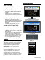
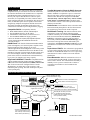
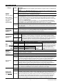
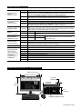
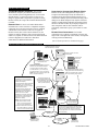
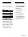
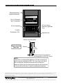
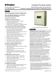
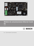
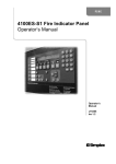
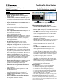
TrueAlarm Fire Alarm Systems UL, ULC, CSFM Listed; FM Approved; MEA (NYC) Acceptance* Fire Alarm Network Annunciators TrueSite Workstations; Version 3.03 Features TrueSite Workstation general features: Simplex® fire alarm network connected graphical interface control Available TCP/IP, LAN/WAN connections; up to 20 remote clients can be connected to the server for multiple remote users; with dedicated and listed Fire Alarm LAN equipment, listed remote clients can have control access Supports standard fire service annunciation icons to provide firefighter and first responders with critical fire response information Custom alarm and system messages can intuitively guide emergency responders; important information (HAZMAT locations, contact information, etc.) can be quickly presented Color graphical annunciation and control capacity for up to 62,500 points or point lists Floatable and dockable windows allows windows to either be fixed (docked) or floatable Quad monitor support allows multiple active windows such as putting the Alarm List Window on one monitor and the Graphics Window on another, or run separate client/server instances on individual monitors, with up to 4 total supported monitors Pan-and-zoom features allow precise dynamic navigation within a graphic screen for rapid and convenient selection of the area of interest Configurable coverage zones allow user defined areas or zones within a graphics screen to be highlighted to indicate the area of activity without zooming into the point of interest Auto-jump allows the screen view to automatically jump to a graphic at a predetermined zoom level with the active device centered on the screen; alternately, the system can be selected to auto-jump to the Alarm List window Captive or Non-Captive modes support dedicated workstation operation (captive) or workstation operation with other Windows applications (word processing, spreadsheet, etc.) where workstation activity takes precedence (non-captive) Extensive historical logging; up to 500,000 events with operator notations; information is compatible with spreadsheet and database programs for report customization Optional interface to Digital Alarm Communicator Receiver (DACR) integrates multiple systems onto a single workstation* Multiple password controlled operator levels with selectable feature access 3rd Party Interface open-architecture solution provides enhanced information access for advanced users Available optional connections for printers or other compatible systems Operates on Windows 7 Professional or Windows 7 Enterprise, 32-bit operation (remote client software is also compatible with 64-bit operation) TrueSite Workstations can Support Multiple Monitors (touchscreen monitors with expanded desktop shown) Enhanced workstation system features: TrueSite Workstation Mobile Client allows compatible iOS mobile devices to access system information Export to XML feature allows TrueSite Workstation data to be easily exported for report generation and customization Test Mode allows unobtrusive testing of selective devices without nuisance interruptions at the operator workstation, events are background recorded with a visual Test Mode indicator in the historical logs Node Name supports including a description of the specific building or area associated with a point in the workstation views and reports Operator Notes allows an operator to log notes associated with individual events for historical records and retrieval DACR Account Filter allows Historical Log Reports to be filtered by DACR Account for quick access and verification of information associated with an individual account Web Browser Command Link enables the ability to easily call up an external web page or link (web-cam, etc.) with a single command button on a graphic screen RAID 1 Support provides a real-time “mirror” image on a secondary hard drive for enhanced life-safety workstation survivability; operation will automatically transition to the alternate drive on a drive failure without loss of operation Vector information to supervised remote clients; select by point, event category, panel, or custom list Email generation is available to send updates to individuals or to distribution lists with selectable content Sound files (WAV) can be used to create custom audible status annunciation using local onboard speakers Fahrenheit or Celsius temperatures can be displayed for screens showing heat sensor temperatures Agency listings*: UL 864 & ULC-S527 as Control Unit Annunciator UL 864 for Fire Proprietary Supervising Station UL 864 UUKL as Firefighter Smoke Control Station UL 1076 & ULC-C1076 for Proprietary Security UL 1610 as Central Station Burglar Alarm Control Unit UL 2572, Mass Notification Systems, as Central Control Station (PGWM); see page 11 for details ULC-S559, Equipment for Fire Signal Receiving Centres and Systems * Refer to page 7 for specific product listing details. CSFM Listing: 7300-0026:323. Accepted for use – City of New York Department of Buildings – MEA35-93E (does not include model 4190-8403). Additional listings may be applicable; contact your local Simplex product supplier for the latest status. Listings and approvals under Simplex Time Recorder Co. are the property of Tyco Fire Protection Products. S4190-0016-30 3/2015 Product Image Reference Features (Continued) Note: Graphics not to scale Graphic screens details: Over 30,000 custom field generated and edited graphic screen capacity is available Multiple import and export formats are supported (refer to page 4 for details) Additional Fire Alarm Network capabilities: Multiple workstations can be nodes on the same fire alarm network to provide redundant operations for improved survivability Connect to up to seven (7) separate network loops Graphical diagnostic tools identify network node and loop status Set-host service functions allow access to remote network node data including individual TrueAlarm analog sensors Provides event printing (with compatible printer), view or print of status and service report information, and print graphic screens (see page 9 for printing details) Compatible with IMS (Information Management Systems) and GCC (Graphic Command Center) on the same fire alarm network 2120 Multiplex Serial Line Interface (SLI) allows connection to up to eight, 2120 Multiplex systems 21.5” Desktop Monitor with a sample Emergency Communications Control Screen (4190-4014) Selectable computer and monitor options: Computers are available as desktop or rack mount with mouse operation and/or touchscreen operation providing convenient user interface Desktop LCD widescreen, high resolution LED backlit monitors are 22 inch class, 21.5 inch (546 mm) diagonal, provide 1920 x 1080 resolution, and are available with or without touchscreen Wall mount LCD widescreen, high resolution monitors are 42 inch (1067 mm) diagonal, provide 1920 x 1200 resolution, and are available with or without touchscreen Rack mount LCD high resolution monitors are 19 inch class 18.5” (470 mm) diagonal with touchscreen and provide 1366 x 768 resolution; Note: Refer to page 12 for important monitor mounting details 42” Wall Mount Monitor Description Desktop PC Network Annunciation. TrueSite Workstations provide annunciation, status display, and control for Simplex Fire Alarm Networks using a personal computer based graphical interface with a high resolution, color display. Response buttons with realistic icons provide control switches specific to the operation being performed. Remote Clients. For remote viewing of TrueSite Workstation Server information, remote clients are available and connected using TCP/IP LAN/WAN Ethernet communications. As detailed on pages 7 and 10, Remote Clients can be annunciation only, or capable of system control when configured with agency listed hardware. reference reference for monitor for 18.5"dimensions screen DACR Compatible. For systems requiring information from remote control panels via DACTs (Digital Alarm Communicator Transmitters), workstations can be equipped to communicate directly with a compatible DACR; refer to page 6 for details. Rackmount PC and Monitor 2 S4190-0016-30 3/2015 TrueSite Workstation Operation Operation. When fire alarm network status changes occur, the screen displays the type and location of the alarm (or other activity) and the appropriate header buttons appear. In the historical log screen below in Figure 1, Fire, Priority 2, Supervisory, and Trouble buttons are shown with an active Trouble indicated. Programmable Activity Timeout allows an unattended monitor to revert to the login screen when the configured time period expires. Individual User Preferences appear when the user logs in. Options include: Font Size (default or large); Toolbar Size (small or large); Interface Theme (MS Office 2003 or System); Floating Window Options (select whether to show Menu bar or show Tool bar). Historical Log and List Details. Figure 1 below shows historical log details. The display format is similar to the display for active list items such as the alarm list. Displayed information can be sorted on-screen by each category shown (number, time, date, point name, etc.). List information can be reviewed on the screen, printed at a local or remote system printer, or can be written to an electronic file for compatibility with spreadsheet and database programs. Customized Response. Custom alarm and trouble messages can be added and field edited to provide operator response assistance. Point specific information, such as hazardous material storage and lists of people to notify, can be automatically or selectively displayed. Sample Screens. Figure 1 (below) is representative of historical log screen detail. Figure 2 (on page 4) is representative of a system graphic screen with icons representing the devices of interest. Screen choices can be configured per system preference. However, when using multiple optional monitors, multiple windows can be visible simultaneously for operator convenience. Ease of Operation. With touchscreen monitors, the operator touches the screen area in alarm (or uses the mouse control) to access a more detailed view of the alarmed zone or device. With the proper password access, the operator has the ability to acknowledge alarm and trouble conditions, activate signal silence, and perform system reset directly from the workstation screens. Figure 1. TrueSite Workstation Sample Historical Log Screen 3 S4190-0016-30 3/2015 Password Control Graphics Screens (Continued) Multiple Access Levels. Operator access level is determined during log-in. Select functional access to match the training and responsibility of the operator. Operators with additional TrueSite Workstation and fire alarm network training may be qualified for access to sensitive areas. For operators who are primarily concerned with immediate facility security, a lower level access will provide the information necessary for proper response but will not allow access to key parameters that determine overall system/network operation. Custom Banner and Main Screen Background. The banner area shown with a Simplex logo in Figure 1 can be customized (bitmap area is 2250 x 68 pixels). The main screen background (viewable prior to login) can be customized with a bitmap of up to 1000 x 525 pixels. Action Messages. In addition to screen text or graphic information, the operator can be presented with specific action messages that provide emergency response information and directions. These action messages are easily field edited for local requirements. The appropriate action message in the screen below would be located in the Acknowledge dialog box. Auto-Jump to Graphics or Alarm List. Select whether activity should cause a jump to a list format or to the associated graphic screen. Supported Graphics Formats: DWG Import Formats: AutoCAD R9, 10, 11-12, 13, 14, 2000-2002, 2004-2006, 2007-2009, 2010-2011 DXF Import Formats: AutoCAD R14 and 2000 Export Formats: AutoCAD 2000 DWG/DXF format (allows editing in AutoCAD 2000 or later) Import drawing files: DWG, WGS, IMS/GCC DOC files, WMF, BMP, GIF, and JPG Graphics Screens Site and Floor Plan Details. Graphics screens can provide easily recognizable site plan and floor plan information. The level of detail can be customized for the specific facility to easily and accurately direct the operator to the immediate area of interest. Graphic Screen Controls. The graphics portion of the screen below is shown as a main screen but could be set to float and be moved to another monitor if desired. Icons can be added to identify the location and type of the device of interest and the graphics control toolbar (located at the top of the graphic) can be used to pan and zoom for more precise detail. Programmable coverage zones can be added with selectable area and zoom level. A fixed area site plan (key plan) with action buttons and screen locator can be added as shown below. Pan and zoom are tracked by a green rectangle in the key plan. Individual Point Service Access Qualified Operator Detail Access. The workstation operator’s interface provides service level access to network information that is not normally “public.” Network “private” point information can be accessed using the SetHost feature, and logging into the database of the network and node of interest. With this operation, individual point information can be accessed and controlled as required by qualified service personnel with proper password access. Figure 2. TrueSite Workstation Sample Graphic Screen with Detail Enlargement and Acknowledge Box (Note: This sample graphic screen demonstrates heat sensors (HS) dynamically displaying their local temperature readings) 4 S4190-0016-30 3/2015 Network Diagnostics Version Compatibility Graphical Network Status Views. Automatic, built-in diagnostics are available to provide graphical views of Network topology and Network status. Missing communications links due to wiring breaks or shorts as well as inactive network nodes are indicated clearly to guide in returning the system to normal. Information screens are available to provide detail about each specific network node. Network level functions such as timekeeper node and monitor node are indicated as well as identification of the node being used for the diagnostic. Compatibility with TrueSite Workstations requires the 4100ES, 4010ES, or other panels per the following software versions. Fire Alarm Network Interface 4190 GCC/IMS/NPU 4100U 4100 4020 4010 4002 Master Version 2.07 (or later) Master Version 11.03 (or later) Master Version 9.02 (or later) Master Version 9.02 (or later) Master Version 3.01 (or later) Network Firmware Version 3.02.92 (or later) 2120 (SLI) Interface 2120 Master Version 5.44 (or later) Network Interface Version 3.02 (or later) Multiple Network Connections When extensive network expansion or interconnection of existing, separate networks is required, up to seven (7) network loops may be connected to the TrueSite Workstation. Each network loop is connected to its own network interface module allowing the workstation to appear as a node in each individual loop. Network Loop 2 With a multi-loop network connection, the TrueSite Workstation is a node member of each network loop with up to 98 additional nodes per loop. This allows up to 686 total nodes and the TrueSite Workstation Server (687 total) to be interconnected. FI RE AL ARM C O NTR O L * * SY STEM 12 : 02: 1 5pm F A I R E LA S Y ST R M S U P E R A LA R M A C K E M S Y S T E M A V I STO R OR YU B SU P V A C K T R AC O K U L S E I I S N O RM AL * * M on L A R M A L E N C EP D O 8- M ar - 99 C W E BL A E L A R M S Y ST E M S I L EN C ER E SE T R C AUT I O N D I S C O N N E CT P O W E R BE FO SERVI CI NG RE Fir e Control Fir e Control Multi-Loop Operation Features Improved survivability: Individual network loops operate independently In the event of loss of one or more loops, remaining loops continue to operate Network Loop 3 Loop independence: Loops can operate at different data rates to satisfy individual conditions (9600 or 57,600 bps, selectable per loop) New loops can be added without impacting existing loops TrueSite Workstation with up to seven (7) Network Interface Modules Assists with phased-in system expansion: Each loop can be installed as a stand-alone network allowing local node programming to evolve as required When construction or renovation reaches completion, loops can be combined for coordinated facility protection Additional Network Connections, up to seven (7) total Fir e Control TrueSite Workstation hardware requirements: Each loop requires a dedicated Network Interface Card with two media modules A maximum of 7 Network Interface Cards are allowed per workstation Network Loop 1 Typical Interface of Multiple Network Loops Using a TrueSite Workstation Server 5 S4190-0016-30 3/2015 DACR Interface DACR Support. For control panels that are not network compatible or may be too remote for a network connection, the TrueSite Workstation can communicate to a compatible DACR (Digital Alarm Communicator Receiver) via an RS-232 port (requires DACR Interface software option 4190-5060, see compatibility list below). Remote control panels equipped with DACTs communicate their local event status (or individual point status if capable) to the DACR using dial-up telephone and optional TCP/IP connections. The DACR forwards the individual panel status to the workstation for information processing and history logging. TrueSite Workstation Points for DACR Accounts. Workstation points are associated with a DACR account number. Standard event points have up to a 19 character label for each point. CID point reporting has up to a 40 character label. DACR event categories include: Fire Alarm, Priority 2 Alarm, Supervisory Alarm, Trouble, Utility Status, and Unknown Point (CID format only). An occurrence of these events will be prefixed with the 19 character account label. Public Points. The Workstation can be selected to make DACR associated points public to the fire alarm network for monitoring by other network nodes if required. DACR Status Tracking. The DACR connection to the workstation is supervised with the following trouble conditions tracked by the workstation: Communications Loss, (between DACR and workstation), Initialization Failed (the workstation to DACR connection did not successfully establish), Unknown DACR Message, (the DACR sent a message that was not understood by the workstation), and Unknown DACR Account (the account information received does not correlate to an workstation point). Supervision of DACTs. The workstation is programmed to expect and log periodic supervisory transmissions from the DACTs via the DACR. Failure to receive a supervisory transmission will cause a trouble event on the TrueSite Workstation. Event Restoration. When the workstation receives an event restoration from the DACR, it restores that point’s status record to normal. The workstation has the ability to manually restore a point to normal in the event that a restoration occurred that was not forwarded to the workstation. Compatible DACRs. Compatibility includes: Bosch Model D6600*, D6100i, and D6100Ipv6 Sur-Gard Model System I, II, III, and IV AES Intellinet 7705i Wireless-to-Internet receiver Sur-Gard Model MLR2-DG (legacy product) * Note: For UL 864 listed Fire Proprietary Supervising Station Operation that uses a DACR, select the Bosch D6600 with CID format and 4190-8403 (see page 7). DACR Events. The TrueSite Workstation handles DACR points as though they were network points. Graphics can be displayed and point status changes can be easily acknowledged. Point acknowledgement occurs locally on the workstation since communications between the DACT and DACR are from DACT to DACR only. Remote panels need to be Acknowledged, Silenced, or Reset at the individual panel. Point events are entered into the workstation history log as part of its 500,000 event storage capacity. Supported DACR/DACT Formats. Compatible DACRs support standard reporting formats including: ADEMCO CID (Contact ID format), SIA Level 1, BFSK; and 3/1 and 4/2. A CID account can be configured on the TrueSite Workstation to be either panel event reporting or with individual point reporting. The other formats provide panel event reporting only. DACR Interface Reference Diagram Wiring to standard Fire Alarm Control Panel Network Loop(s) Simplex 4190 Series TrueSite Workstation Alternate connection; AES Intellinet 7170 Series Wireless Transceiver Equipment SG-System III RS-232 link; 6 ft long (1.8 m) cable supplied with 4190-5051 Location 1* TCP/IP WAN/LAN Compatible DACR: Sur-Gard Model System I, II, III, or IV Bosch Model D6600, D6100i, or D6100IPv6 AES Intellinet 7705i (refer to product for details) Alternate path via Dial-up connection for compatible Sur-Gard and Bosch DACRs (may require optional modules, refer to product for details) Telephone line connection (POTS) Location 2* Location 3* * Remote Fire Alarm Panels with TCP/IP communicators such as DSC TL300 (UL & ULC listed) or Bosch C900V2 (UL listed only) Location 4* AES Intellinet 7788 wireless communicator (compatible non-Simplex panels) 6 Location n S4190-0016-30 3/2015 Product Selection Category Model 4190-8401 Description TrueSite Workstation with control capability; requires selection of computer, monitor, and software from list below Listings: For use as a Workstation Annunciator under: UL 864 & ULC-S527, Fire Alarm Control; UL 1076, Proprietary Burglar Alarm; UL 1610 Central Station Burglar Alarm TrueSite Workstation with control capability; includes bracket for securing AC input wiring; requires selection of computer, monitor, and software from list below Listings: UL 864 as Fire Proprietary Supervising Station and ULC-S559, Proprietary Fire Signal Receiving Equipment, requires direct wired AC Power and UPS secondary power source per applicable local code; reports and logs events; if an optional event printer is also desired, see page 9 for printer Note: LAN/WAN 4190-8403 information; if using a DACR for UL 864 listing, select the Bosch D6600 with CID format; for ULCC-S559, connections require see page 6 for compatible DACRs) use of Transient Suppressor UL 864, UUKL Firefighter Smoke Control Station; UL 1076, Proprietary Burglar Alarm Multiplex 4190-6010, see Receiving Unit; UL 1610, Central Station Burglar Alarm Control Unit and ULC-C1076, Proprietary page 8 for details Burglar Alarm Central Station Control Unit with listed DACR (see page 6 for compatibility) Hardware Systems (select as required) TrueSite Workstation Remote Client; requires selection of computer, monitor, and software from list below; agency listed control capability requires connection to a dedicated Fire Alarm LAN (refer to data 4190-8410 sheet S4190-0018) Listings: UL 864 & ULC-S527, Remote Client Annunciator Software Only and Aftermarket Additions Computer Type (select one as required) LCD Color Monitor TrueSite Workstation Software Only package, refer to page 9 for computer specifications reference 4190-8603 (listings and approvals are not applicable); [NOTE: Windows operating system is not provided. For software only packages purchase operating system locally as required.] 4190-8901 Aftermarket hardware addition 4190-8605 Aftermarket software addition Computer with Intel i7, 2.10 GHz CPU, 6MB Cache, 4GB RAM, (2) 1TB Hard Drives (minimum) 4190-7015 Desktop with RAID 1 Controller, USB ULIO card, DVD R/W, integral audio and amplified speakers, onboard video for up to two displays (1) SVGA and (1) DVI, 2 RS232 Serial ports, 6 USB ports, 1 PS/2 port, dual Gigabit LAN, Passive backplane with (8) PCI, (3) PCIe x 1 and (1) PCIe x 16 Rack slot, keyboard, and mouse; charcoal grey housing; Computers are pre-installed with Windows 7 4190-7016 Mount Professional (includes CD and license) and with TrueSite Workstation software. Model Size (Diagonal) Description 4190-7131 21.5” (546 mm) LCD Monitor for desktop applications Monitor Only 4190-7114 42” (1049 mm) LCD Monitor for horizontal wall mount applications Monitor 4190-7233 21.5” (546 mm) with 4190-7234 18.5” (470 mm) Touchscreen 4190-7214 42” (1049 mm) Applications Software (select one per application) Select one minimum, four maximum, as required per computer choice; select 4190-6038 Dual Video Card as required (see below); connect as SVGA or DVI, Desktop LCD Monitor with both cables are included; touchscreen Rack Mount (see page 12) touchscreen and models include separate serial built-in serial controller cable; black/charcoal grey Wall Mount controller housings Model Description TrueSite Workstation Server Software, includes: License, Security Dongle, Documentation; requires 4190-5050 4190-8401, 4190-8403, or 4190-8603 4190-5053 TrueSite Remote Client Installation CD, no operating system; requires 4190-8410 or 4190-8605 4190-5060 DACR Interface for a TrueSite Workstation Server 4190-5064 Server Feature Options 3rd Party Interface Software Package; includes: (1) 3rd Party Interface Development Software; (2) A dedicated Security Certificate allowing server and client access for one 3rd Party Interface Application; and (3) A 3rd Party Feature Code allowing one 3rd Party Client connection to a single TrueSite Workstation; Note: A 579-1155 Software Customer Information Form is required to be submitted with the order TrueSite Workstation Feature Upgrade; includes the latest TrueSite Workstation software version and an Upgrade Feature Code to enable new standard features (new optional features are selected 4190-5065 separately); without this upgrade, installing the latest software version provides updated performance improvements over previous versions but does not include new standard software features TrueSite Workstation Mobile Client Feature; quantity of one (1) enables TrueSite Workstation information 4190-5067 to be accessed from compatible mobile devices; access for mobile clients is enabled by programming at the server; see data sheet S4190-0024 for more information; requires Version 3.03 or higher Remote Client Type Selection (Select One Per Remote Client) 4190-5061 Feature code for Remote Client with restricted features (reduced feature set) 4190-5062 Feature code for Remote Client with password protected feature access 3rd Party Interface Client for adding additional 3rd Party Client connections to an existing TrueSite Workstation 3rd Party Interface; includes a 3rd Party Client Feature Code for the selected quantity of concurrent 3rd Party Client Connections to a single TrueSite Workstation (maximum of five (5) per server) 4190-5066 Note 1: When adding 3rd Party Interface Clients to more than one TrueSite Workstation Server, each server requires its own 4190-5066 Remote Client Selection; if a new 3rd Party Interface Application is being developed, feature code 4190-5064 will be required to provide a unique Security Certificate. Note 2: A 579-1155 Software Customer Information Form is required to be submitted with the order. Please note that equipment and specifications may vary due to equipment design changes. 7 (continued on next page) S4190-0016-30 3/2015 Product Selection (Continued) Model Internal Hardware Options (select as required) 4190-6034 4190-6038 Transient Suppressed Connectors (select as required) 4190-6002 4190-6026 4190-6010 Description Quad RS-232 Serial Port Card, select when more than two serial ports are required; may be needed for 2120 SLI connections; PCI Slot card with pluggable terminal block output; up to 2 maximum; one 4190-6026 suppressor is require per connection (see below) Dual Video Card, PCI Slot; select two for support of 3 or 4 monitors; Note: Dual monitor support is standard; for 3 or 4 monitors, disable onboard video drive and use 4190-6038 cards Transient Protected Connector, select one per connection to a standard RS-232 serial port Transient Protected Connector for Quad Serial Port Card; one required per connection Transient Suppressor for LAN/WAN Connection; required for agency listing for each TrueSite Workstation Server and Remote Client LAN/WAN connection, except for server to client connections when both are in the same room; refer to diagram on page 10 Upgrade to DACR 4190-9807 Upgrade standard TrueSite Workstation (with Version 1.x software) or Information Management System (IMS), to add DACR capability; includes USB style Security Dongle (requires an available USB port); Note: Use 4190-5060 for Version 2 (or later) systems Network Interface Modules (seven (7) maximum) Configured Aftermarket Description 4190-6061 4190-9829 Modular Network Interface (select Media Modules separately, listed below); PCI Slot card Media Modules for Modular Network Interface (as required) 4190-6036 4190-9822 Wired Media 4190-6037 4190-9823 Fiber Optic Media Model Select one per input and one per output media type, per Modular Network Interface; mounts onto Modular Network Interface (see above) Description Hardware upgrade to migrate from Windows XP to Windows 7 operation for computer identification 51-TSP12-969 only; includes 1 GB RAM, cable, reset switch, and mounting bracket (mounting bracket replaces existing floppy disc drive cover plate) System Upgrades (select as required) 4190-9814 Programming (select) 4190-8122 TrueSite Workstation Programming; select Programming Items below 4190-4006 4190-4008 4190-4009 4190-4010 AutoCAD DXF or DWG file, one floor plan (multiple floor plans require dedicated files) 25 Custom Action Messages 25 Travel Screen Keys (selective zooming) 25 Status Icons 4190-4011 4190-4012 4190-4013 4190-4014 25 Control Functions; On/Off, Bypass, etc. Convert one (1) Existing IMS Screens to TrueSite Workstation Screen 10 Coverage Zones; order quantity as required One (1) Emergency Communications/Mass Notification Control Screen (see screen on page 2) Programming Items (select items per system requirements; select quantity of items as required) requires selection of 4190-8122 Hardware Reference with 21.5” Desktop Monitor 6-3/4" D (171 mm) 20-3/16" W (513 mm) 17-5/8" D (448 mm) 16-7/8" W (429 mm) 15" H (381 mm) 7" H (178 mm) TrueSite Workstation CPU 8 S4190-0016-30 3/2015 TrueSite Workstation Equipment Specifications Computers and Accessories (Please note that equipment and specifications may vary due to equipment design changes) Model* Description 4190-7015 Desktop Computer 4190-7016 Rack Mount Computer NA Dimensions 16 ⅞” W x 7” H x 17 ⅝” D (429 mm x 178 mm x 448 mm) 19” W x 7” H x 17 ⅝” D (483 mm x 178 mm x 448 mm) AC Power Input* 2 A @ 120 VAC, 60 Hz (240 W) Operating Range: 95-132 VAC; 180-264 VAC, auto-range; 50/60 Hz 19” W x 1 ¾” H x 12 ¾” D (483 mm x 44 mm x 324 mm) Rack Mount Keyboard Tray (included with computer) NA LCD Monitors (Please note that equipment and specifications may vary due to equipment design changes) Model* 4190-7131 4190-7233 Description 21.5” Desktop 21.5” Desktop with Touchscreen Dimensions 3 20 ⁄16” W x 15” H x 6 ¾” D (513 mm x 381 mm x 171 mm) 3 AC Power Input* 0.4 A @ 120 VAC, 60 Hz (48 W) Operating Range: 100-240 VAC, 50/60 Hz 11 20 ⁄16” W x 15” H x 8 ⁄16” D (513 mm x 381 mm x 221 mm) 1 4190-7234 18.5” Rack Mount with Touchscreen 4190-7114 42” Wall Mount 4190-7214 42” Wall Mount with Touchscreen Supplied Video Cables 17 ¾” W x 11 ⁄16” H x 2.022” D (451 mm x 281 mm x 51.4 mm) 1.5 A @ 120 VAC, 60 Hz Operating Range: 100-240 VAC, 50/60 Hz Note: Refer to page 12 for important monitor mounting details 2.02 A @ 120 VAC, 60 Hz (243 W) Operating Range: 100-240 VAC, 50/60 Hz 5 41 ⁄16” W x 25 ¼” H x 5” D (1049 mm x 641 mm x 127 mm) (1) DVI and (1) SVGA, 6 ft (1.8 m) long (1) DVI and (1) SVGA, 15 ft (4.57 m) long * Note: Products are Agency listed for 120 VAC. Computers and monitors are shipped with 120 VAC cord; NEMA 5-15P plug to IEC-320 C-13 connector. For use with other voltages, locally obtain a cord in compliance with local safety standards. Computer Minimum Specifications Reference** Server Enclosure** Server Computer** Remote Client Passive backplane with: 7 PCI slots, 2 ISA slots, and 1 CPU slot; security features: key lock reset switch; fan monitor card; locked door protecting access to the CD/DVD R/W drives and one front mounted USB port Microsoft Windows 32-bit 7 Professional or Windows 7 Enterprise operating system; Intel i7 2.1 GHz CPU, or Core 2 Duo 2.1 GHz CPU, 2 GB RAM, 40 GB minimum hard drive; 2 Serial ports, 1 Parallel port, 2 USB ports, dual Gigabit LAN, 1 PS/2 mouse port, 1 PS2 mouse & keyboard adapter cable; SVGA video output with 16 MB VRAM, CD/DVD R/W, 101 keyboard, PS/2 mouse, PCI and ISA slots (as required), integral audio and amplified speakers Remote Client specifications are similar to server except: also compatible with 64-bit versions of the Windows 7 operating systems, and compatible with Microsoft Windows 7 Home Premium operating system (32-bit or 64-bit); Pentium 4 CPU minimum, 1 GB RAM minimum; 1 Serial port, 1 Parallel port, single Gigabit LAN, 20 GB hard drive, 4 MB VRAM, USB ports and CD drives (optional) ** PLEASE NOTE: Simplex 4190 Series computers are Agency listed for use with TrueSite Workstation software. For applications where Agency listings are not required, TrueSite Workstation software should be compatible with most computers meeting the stated minimum specifications. However, due to computer manufacturers potentially using unique and/or proprietary drivers, hardware, or other software not tested with TrueSite Workstation software, there may be incompatibilities. If other computers are used, proper operation with TrueSite Workstation software may require technical adjustments by a qualified computer technician and would be the sole responsibility of the computer supplier and computer manufacturer. Computer Port Reference (4190-7015 and 4190-7016) RS-232 Serial Ports Two standard, up to 9 total with optional 4190-6034 Quad Serial Port Card USB Serial Ports 3 total; 2 in the rear (one is used for Server Security Dongle), and 1 in the front behind the locked door Other Ports Event Printing Other Printing Printable Information Two Ethernet ports and one Parallel port For agency listed Proprietary Supervising Station operation and for other operations, if an event printer is desired, a supervised and dedicated Simplex Model 4190-9013 agency listed dot matrix printer is recommended; connection is to USB, Serial, or Parallel Port of the Server PC (see data sheet S4190-0011 for printer details) For Report, Screen, or Graphics printing, a Windows 7 compatible printer may be used; connection may be USB, Serial, Parallel, or LAN/WAN connection via Ethernet Event printing (with supervised and dedicated dot matrix printer 4190-9013 as explained above) Auto-print of auto-jump graphics; prints to Windows default printer Reports: Historical logs, System Activity, TrueAlarm Status, TrueAlarm Service, Analog Monitor ZAM Calibration, and Active List; displayed reports can print to a LAN connected (unsupervised) printer Screen captures (configurable as negative images to reverse black backgrounds) Environmental Specifications Operating Temperature 32° to 120° F (0° to 49° C) Operating Humidity Up to 93% RH, non-condensing, at 90° F (32° C) 9 S4190-0016-30 3/2015 Server/Client Operation Supervised or Unsupervised Remote Clients. Remote Clients can be designated as Supervised or Unsupervised. When Supervised, the connection is monitored by the TrueSite Workstation and a loss of connection is audibly reported at both ends along with a dialog screen. When unsupervised, only the client end displays a trouble dialog indicating disconnection from the Server. Remote clients may be laptop computers or other computers used for other functions and are periodically connected to query system status or create reports. TrueSite Workstation Computer. The TrueSite Workstation computer provides the functions of the Server and the system configuration tools. To access the desired features, a system/job specific security service dongle is supplied and is required. For systems not using Remote Clients, the setup of the TrueSite Workstation PC is similar. Remote Client. For access to TrueSite Workstation information at a remote location, a compatible computer, connected via a Local Area Network (LAN) is equipped with Remote Client software. There are two types of Remote Clients, those with a restricted feature set (not capable of control); and those with a password protected feature set (capable of control). Refer to the interconnection reference diagram below and refer to data sheet S4190-0018 for additional information. Remote Client Connections. The TrueSite workstation server supports a maximum of twenty (20) Supervised or Unsupervised remote clients, each capable of being on-line simultaneously. (Server/Client Operation is continued next page) Server/Client Interconnection Reference to additional Remote Fire Alarm Ethernet Switches (if required) Remotely Located Fire Alarm Ethernet Switch S FIRE ALARM ETHERNET SWITCH Local Fire Alarm Control Panel Remote Fire Command Center with Remote Client Fire Alarm Network connection Fire Control Dedicated Fire Alarm LAN for connection between Fire Alarm Ethernet Switches: 1. Ethernet cable, up to 328 ft (100 m) 2. Multimode fiber, up to 1.24 mi (2 km) 3. Single-mode fiber, up to 9.3 mi (15 km) NOTE: Fiber optic connections require two fibers, Transmit and Receive General System Notes: 1. Available ports can be connected to other Switches to extend distance or extend Client capacity. 2. Fire Alarm Ethernet Switch 4190-6050 can support up to 7 clients and one server per Switch, or up to 7 clients at a remote Switch location. 3. Fire Alarm Ethernet Switches with fiber optic ports (4190-6054 and 4190-6055) have 4 wired Ethernet ports to connect to TrueSite Workstations, and 2 fiber optic ports for connection to other Switches with fiber optic ports. (Refer to Product Selection for details.) Fire Alarm Ethernet Switch Connections between Fire Alarm Ethernet Switches and TrueSite Workstation, Server or Client are wired Ethernet cable, up to 328 ft (100 m) Connections to local fire alarm panel to supply power and monitor trouble using IDNet communications with on-board IAM or by monitoring relay contacts FIRE ALARM ETHERNET SWITCH S Fire Alarm Control Panel Remote Client 4. NOTE: Client Connections details: S 4.1 With server revision 2.04 and above, up to twenty (20) clients may be on-line simultaneously. 4.2 Server revisions before 2.04 with remote clients allow up to ten (10) clients to be online simultaneously. TrueSite Workstation Server Fire Alarm Network Loop Connections (up to 7 loop capacity) S NOTE: 4190-6010 Transient Suppressor assemblies are required for agency listing for each Server and Remote Client LAN/WAN connection, except server to client connections when both are in the same room; (designated as “S”, located and connected at rear of computers) Facility LAN Facility Fire Alarm Maintenance Center (restricted client) Internet Connection 10 Off-site access (restricted client) S4190-0016-30 3/2015 Server/Client Operation (Continued) Mass Notification Systems Reference TCP/IP Networks. The minimum recommended connection speed for TrueSite Workstation Server or Remote Client to a TCP/IP local area network is 3 Mbps. The TrueSite Workstation operates as a UL 2572 listed Central Command Station (CCS) when configured per the following: Anti-Virus Software. When either the TrueSite Workstation Server or Remote Client computer is connected to a TCP/IP network other than a dedicated Fire Alarm network, it is highly recommended that regularly updated anti-virus software protection be installed on each connected computer. The TrueSite Workstation has been verified as compatible with Symantec EndPoint Protection 12.1 and McAfee Enterprise 8.8. 1. 2. 3. Additional Reference Description Installation and Checkout Instructions Operation and Application instructions Software Upgrade Instructions TrueSite Workstation Configurator Reference Manual Quick Reference Operator Instructions TrueSite Workstation Parts List TrueSite Workstation 3rd Party Interface Software Customer Information Form Localization Procedure Release Notes TSW Mobile Client User Guide Document 4. 579-834 579-835 579-838 5. 579-844 579-878 579-888 579-1155 6. 579-946 579-1018 579-1154 General System Listings Reference The following functions are agency listed with the computers and monitors identified under Product Selection on page 7: Select model 4190-8401 (Note: Cannot be used for Supervising Station or Security Monitor applications) Provide an audio system microphone mounted adjacent to the TrueSite Workstation, either located within a 4100ES (or 4100U) Fire Alarm Control Panel or Remote Annunciator Panel, or use a Remote Microphone Assembly. The 4100ES/4100U microphone options are Model 4100-1243 for Fire Alarm Control Panels and Model 4100-1244 for Remote Annunciator Panels (refer to data sheet S4100-0034 for details). Remote Microphone Assembly Model 4003-9803 mounts separate from the control panel (refer to data sheet S4100-0053 for details). Note: At least two monitors must be connected to provide the necessary display information (see exception below). One monitor is required to display the speaker zone status and the other monitor is required to display the event screen. Exception: If a 4100ES/4100U Network Display Unit (NDU) is mounted adjacent to the TrueSite Workstation for network audio control with microphone access, a second monitor may not be necessary if the audio control status is viewable. Review the application with the local authority having jurisdiction (AHJ). TrueSite workstation PCs, whether stand-alone or functioning as a server to remote clients Supervised Remote Clients with protected features that are connected to the server using a dedicated Fire Alarm Network as described on page 10 Refer to data sheet S4190-0018 for details about Fire Alarm Network Ethernet Switches Additional agency listings reference: Restricted feature Remote Clients software on compatible computers (listed for standard office use) provide annunciation features only and can be connected using a facility LAN without system listing impact 11 S4190-0016-30 3/2015 Rack Mount Hardware Reference with 18.5” Monitor Rack equipment is supplied separately 18.5" LCD Monitor with Touchscreen reference reference for monitor for 18.5"dimensions screen 1/4 turn locking fasteners (right side only) 1/4 turn fasteners TrueSite Workstation CPU Keyboard tray Monitor mounting plate Monitor Detailed Side View Monitor 12-7/32" (310 mm) Monitor extension from back of mounting plate = 2.022" (51.4 mm) NOTE: The monitor mounting plate attaches to the rack mounting rail and the monitor will extend 2.022" (51.4 mm) from the front of the mounting rail. Review the specified rack enclosure to determine actual monitor extension beyond the rack frame and to ensure that a rack door (if used) has adequate clearance. TYCO, SIMPLEX, and the product names listed in this material are marks and/or registered marks. Unauthorized use is strictly prohibited.. Microsoft and Windows are trademarks of Microsoft Corporation in the United States and/or other countries. Pentium is a trademark of Intel Corporation. AutoCAD is a trademark of Autodesk, Inc. Symantec is a trademark of Symantec Corporation. McAfee is a trademark of McAfee Inc. Sur-Gard DACRs are a product of Digital Security Controls Ltd (DSC), a Tyco company. Contact ID is a trademark of Pittway Corporation. Tyco Fire Protection Products • Westminster, MA • 01441-0001 • USA www.simplex-fire.com S4190-0016-30 3/2015 © 2015 Tyco Fire Protection Products. All rights reserved. All specifications and other information shown were current as of document revision date and are subject to change without notice.