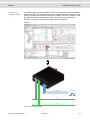
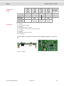
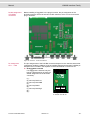
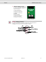
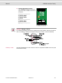
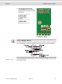
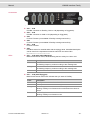
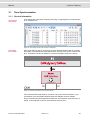
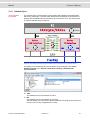
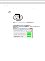
1
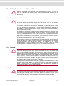
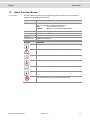
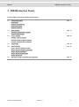
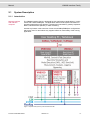
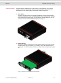
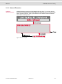
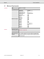
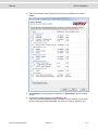
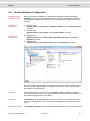
Manual VN8900 Interface Family VN8910A / VN8912 / VN8950 / VN8970 / VN8972 Version 4.0 English Imprint Vector Informatik GmbH Ingersheimer Straße 24 D-70499 Stuttgart The information and data given in this user manual can be changed without prior notice. No part of this manual may be reproduced in any form or by any means without the written permission of the publisher, regardless of which method or which instruments, electronic or mechanical, are used. All technical information, drafts, etc. are liable to law of copyright protection. Copyright 2015, Vector Informatik GmbH. All rights reserved. Manual Introduction Table of contents 1 Introduction 4 1.1 Safety Instructions and Hazard Warnings 1.1.1 Proper Use and Intended Purpose 1.1.2 Hazards 1.1.3 Disclaimer 5 5 5 5 1.2 About this User Manual 1.2.1 Certification 1.2.2 Warranty 1.2.3 Registered Trademarks 6 7 7 7 2 VN8900 Interface Family 8 2.1 System Description 2.1.1 Introduction 2.1.2 Real-Time Processing 2.1.3 Stand-Alone Mode 2.1.4 Network Extension 9 9 11 11 12 2.2 Base Modules 2.2.1 VN8910A Single Module System 2.2.2 VN8912 Base Module 13 13 16 2.3 Plug-In Module 2.3.1 VN8950 CAN/LIN Module 2.3.2 VN8970 FlexRay/CAN/LIN Module 2.3.3 VN8972 FlexRay/CAN/LIN Module 20 20 26 37 2.4 Accessories 48 2.5 Getting Started 2.5.1 Step 1: Driver Installation (USB) 2.5.2 Step 2: Driver Installation (Ethernet) 2.5.3 Step 3: Device Installation 2.5.4 Step 4: Device Configuration 2.5.5 Step 5: Quick Test 49 49 49 49 50 50 2.6 Mounting of Plug-In Modules and Piggybacks 51 3 Common Features 54 3.1 Time Synchronization 3.1.1 General Information 3.1.2 Software Sync 3.1.3 Hardware Sync 55 55 57 58 4 Driver Installation 60 4.1 Minimum Requirements 61 4.2 Hints 62 4.3 Vector Driver Setup 63 4.4 Vector Hardware Configuration 65 4.5 Loop Tests 4.5.1 CAN 4.5.2 FlexRay 4.5.3 MOST 4.5.4 Ethernet 67 67 70 71 72 © Vector Informatik GmbH Version 4.0 -3- Manual Introduction 1 Introduction In this chapter you find the following information: 1.1 Safety Instructions and Hazard Warnings Proper Use and Intended Purpose Hazards Disclaimer page 5 1.2 About this User Manual Certification Warranty Registered Trademarks page 6 © Vector Informatik GmbH Version 4.0 -4- Manual 1.1 Introduction Safety Instructions and Hazard Warnings Caution: In order to avoid personal injuries and damage to property, you have to read and understand the following safety instructions and hazard warnings prior to installation and use of this interface. Keep this documentation (manual) always near the interface. 1.1.1 Proper Use and Intended Purpose Caution: The interface is designed for analyzing, controlling and otherwise influencing control systems and electronic control units. This includes, inter alia, bus systems like CAN, LIN, K-Line, MOST, FlexRay, Ethernet and/or BroadR-Reach. The interface may only be operated in a closed state. In particular, printed circuits must not be visible. The interface may only be operated (i) according to the instructions and descriptions of this manual; (ii) with the electric power supply designed for the interface, e.g. USB-powered power supply; and (iii) with accessories manufactured or approved by Vector. The interface is exclusively designed for use by skilled personnel as its operation may result in serious personal injuries and damage to property. Therefore, only those persons may operate the interface who (i) have understood the possible effects of the actions which may be caused by the interface; (ii) are specifically trained in the handling with the interface, bus systems and the system intended to be influenced; and (iii) have sufficient experience in using the interface safely. The knowledge necessary for the operation of the interface can be acquired in workshops and internal or external seminars offered by Vector. Additional and interface specific information, such as „Known Issues“, are available in the „Vector KnowledgeBase“ on Vector´s website at www.vector.com. Please consult the „Vector KnowledgeBase“ for updated information prior to the operation of the interface. 1.1.2 Hazards Caution: The interface may control and/or otherwise influence the behavior of control systems and electronic control units. Serious hazards for life, body and property may arise, in particular, without limitation, by interventions in safety relevant systems (e.g. by deactivating or otherwise manipulating the engine management, steering, airbag and/or braking system) and/or if the interface is operated in public areas (e.g. public traffic, airspace). Therefore, you must always ensure that the interface is used in a safe manner. This includes, inter alia, the ability to put the system in which the interface is used into a safe state at any time (e.g. by „emergency shutdown“), in particular, without limitation, in the event of errors or hazards. Comply with all safety standards and public regulations which are relevant for the operation of the system. Before you operate the system in public areas, it should be tested on a site which is not accessible to the public and specifically prepared for performing test drives in order to reduce hazards. 1.1.3 Disclaimer Caution: Claims based on defects and liability claims against Vector are excluded to the extent damages or errors are caused by improper use of the interface or use not according to its intended purpose. The same applies to damages or errors arising from insufficient training or lack of experience of personnel using the interface. © Vector Informatik GmbH Version 4.0 -5- Manual 1.2 Introduction About this User Manual Conventions In the two following charts you will find the conventions used in the user manual regarding utilized spellings and symbols. Style Utilization bold Blocks, surface elements, window- and dialog names of the software. Accentuation of warnings and advices. [OK] Push buttons in brackets File|Save Notation for menus and menu entries Microsoft Legally protected proper names and side notes. Source Code File name and source code. Hyperlink Hyperlinks and references. <CTRL>+<S> Notation for shortcuts. Symbol Utilization Here you can obtain supplemental information. This symbol calls your attention to warnings. Here you can find additional information. Here is an example that has been prepared for you. Step-by-step instructions provide assistance at these points. Instructions on editing files are found at these points. This symbol warns you not to edit the specified file. © Vector Informatik GmbH Version 4.0 -6- Manual Introduction 1.2.1 Certification Certified Quality Vector Informatik GmbH has ISO 9001:2008 certification. The ISO standard is a globManagement System ally recognized standard. 1.2.2 Warranty Restriction of warranty We reserve the right to change the contents of the documentation and the software without notice. Vector Informatik GmbH assumes no liability for correct contents or damages which are resulted from the usage of the documentation. We are grateful for references to mistakes or for suggestions for improvement to be able to offer you even more efficient products in the future. 1.2.3 Registered Trademarks Registered trademarks All trademarks mentioned in this documentation and if necessary third party registered are absolutely subject to the conditions of each valid label right and the rights of particular registered proprietor. All trademarks, trade names or company names are or can be trademarks or registered trademarks of their particular proprietors. All rights which are not expressly allowed are reserved. If an explicit label of trademarks, which are used in this documentation, fails, should not mean that a name is free of third party rights. Windows, Windows 7, Windows 8.1 are trademarks of the Microsoft Corporation. © Vector Informatik GmbH Version 4.0 -7- Manual VN8900 Interface Family 2 VN8900 Interface Family In this chapter you find the following information: 2.1 System Description Introduction Real-Time Processing Stand-Alone Mode Network Extension page 9 2.2 Base Modules VN8910A Single Module System VN8912 Base Module page 13 2.3 Plug-In Module VN8950 CAN/LIN Module VN8970 FlexRay/CAN/LIN Module VN8972 FlexRay/CAN/LIN Module page 20 2.4 Accessories page 48 2.5 Getting Started Step 1: Driver Installation (USB) Step 2: Driver Installation (Ethernet) Step 3: Device Installation Step 4: Device Configuration Step 5: Quick Test page 49 2.6 Mounting of Plug-In Modules and Piggybacks page 51 © Vector Informatik GmbH Version 4.0 -8- Manual 2.1 VN8900 Interface Family System Description 2.1.1 Introduction Network interface with real-time computer The VN8900 interface family is designed for high-performance applications in combination with CANoe/CANalyzer. The application areas include system simulations or bypassing applications with Simulink, remaining bus simulations, gateway implementations, test executions (MiniHIL) or data monitoring. Another key feature is the execution of time-critical CANoe/CANalyzer configurations without any user PC and without any negative effects on functionality of the running application. Figure 1: Operator side (user PC) and measurement side © Vector Informatik GmbH Version 4.0 -9- Manual Hardware flexibility VN8900 Interface Family Another important VN8900 product characteristic is the modularity of the network interface, which lets users flexibly adapt it to the measurement environment and existing buses. The overall system is comprised of these components: Base Module Processor unit with memory for executing simulations and time-critical program sections in stand-alone mode. The Base Module has an Intel processor and basic port connections for power supply, synchronization, USB and Ethernet. You will find further details on Base Modules beginning on page 13. Figure 2: VN8910A back side Plug-In Module The Plug-In Module represents the actual network interface; it provides the related interfaces as plug connections (e. g. FlexRay, CAN, LIN or digital-analog input/output). You will find additional details on Plug-In Modules beginning on page 20. Figure 3: VN8910A with inserted VN8950 CAN/LIN Module © Vector Informatik GmbH Version 4.0 - 10 - Manual VN8900 Interface Family Piggybacks Piggybacks establish the connection from the Vector network interface to the user’s electrical networks via appropriate transceivers (FlexRay/CAN/LIN...). Moreover, the Piggyback usually offers the electrical isolation to protect the measurement hardware as well as the system under test. The amount and kind of supported Piggybacks varies between the Plug-In Modules. Please find the list of valid combinations in section "Transceiver Compatibility" of the accessories manual on the driver CD in \Documentation\Accessories. Figure 4: Piggyback 2.1.2 Real-Time Processing General When requirements for timing precision are strict, the measurement hardware must be able to operate with very low latency. The integrated processor of the VN8900 interface family meets this standard and offers significantly improved latency times compared to normal PCs. CANoe The VN8900 interface family is a real-time hardware that is designed for using with CANoe. CANoe offers the option of executing real-time relevant simulations and test functions on the VN8900 – separate from the graphic user interface. On the one hand, this increases overall system performance, and on the other it enables shorter latency times and more precise timers. Configuration of the simulation and evaluation are performed on a standard PC (CANoe), while the simulation and test kernel are executed on the VN8900 (CANoeRT). Communication between the two computers is routed via a USB cable (see Figure 1). 2.1.3 Stand-Alone Mode CANoe configuration The VN8900 interface family offers a stand-alone mode which allows a measurement without any additional user PC. For this purpose a measurement application can be configured in CANoe, which is then written into the permanent memory of the VN8900. After a restart, the configuration is loaded and the measurement autonomously started. Figure 5: Booting overview © Vector Informatik GmbH Version 4.0 - 11 - Manual VN8900 Interface Family 2.1.4 Network Extension Additional network channels CANoe/CANalyzer supports a single Base Module at a time. To use more network channels, the VN8900 interfaces offer additional USB (host) ports to connect to other Vector network interfaces. Time synchronization of the different network interfaces can be done via the sync line. Figure 6: Extension example © Vector Informatik GmbH Version 4.0 - 12 - Manual 2.2 VN8900 Interface Family Base Modules 2.2.1 VN8910A Single Module System Description Base Module with integrated PC processor unit for running real-time applications, which accepts a single Plug-In Module (see section Plug-In Module on page 20). Figure 7: VN8910A back and front side (with VN8950 Plug-In Module) Connections Figure 8: VN8910A back side Ethernet For Vector devices. Currently supported: VX1060, VX1121. USB 1/2 (host) Both ports are used to connect other Vector USB devices for use with CANoe or CANalyzer. The summarized output current at these ports is limited to 500 mA. Supported Device Max. Number of Devices externally powered USB powered CANcaseXL / log 2 1*) VN1630 / VN1640 not applicable 1 VN2610 / VN2640 2 not applicable VN3600 2 not applicable VN5610 2 not applicable VN7600 2 not applicable *) A second Vector device has to be externally supplied. © Vector Informatik GmbH Version 4.0 - 13 - Manual VN8900 Interface Family Note: The Vector device has to be connected to the VN8910A before powering the VN8910A. Note: Please ensure that the USB logo on the USB cable is on the bottom side (USB pins at top) before connecting. Do not force the cable into the USB connector to avoid mechanical damages. Keypads F2/F3/F4 These keys can be assigned to CAPL functions. Keypad Start/Stop This key instantly starts or stops a preconfigured CANoe measurement. LED (Start/Stop) This LED lights up when the CANoe measurement is running. LED S1/S2 These LEDs offer a visual feedback for active measurements and can be individually controlled via CAPL. USB (device) Interconnect your PC and the VN8910A via this USB port to install the device and to use it together with measurement applications (e. g. CANoe, CANalyzer). Sync This terminal (Binder type 711) can be used for time synchronization of different Vector devices (see section Time Synchronization on page 55). Power For its power supply, the VN8910A has a two-pin ODU connector (MINI-SNAP size 1, type GG1L0C-P02RP00-0000). Attach the enclosed power cable to power up the unit (matching ODU connector type S11L0C-P02NPL0-6200). Pin 1: + Pin 2: GND Internal access Mini-USB The Base Module has a service port that is accessible via an internal Mini-USB connector. This (bus-driven) port is used to reset the device to its delivered condition or to update the operating system. Note: Please note that the device must not be powered via the ODU connector while the Mini-USB port is being used. Internal slot for microSD cards This slot is reserved for future use. Recommended cards: ATP Industrial Grade microSD. © Vector Informatik GmbH Version 4.0 - 14 - Manual Technical data VN8910A VN8900 Interface Family Processor Intel ATOM 1.6 GHz E680T Memory 1 GB Hard drive SSD, 4 GB Transceiver Depends on the Plug-In Module and its Piggybacks PC interface USB 2.0 Temperature range Operating: -40 °C...+60 °C Shipping and storage: -40 °C...+85 °C Relative humidity of ambient air 15 %...95 %, non-condensing Technical data VN8910 USB 1/2 output current Max. 500 mA, both ports combined External power supply 6 V...36 V DC Power-up: 9 V DC Power consumption Typ. 9.0 W without Plug-In Module Start-up time Approx. 30 seconds Dimensions (LxWxH) 190 mm x 170 mm x 60 mm Operating system requirements Windows 7 (SP1), 32 bit or 64 bit Windows 8.1, 32 bit or 64 bit Ethernet 10/100/1000 Mbit Supported Plug-In Modules VN8950/VN8970 Processor Intel ATOM 1.6 GHz Z530 Memory 1 GB Hard drive SSD, 2 GB Transceiver Depends on the Plug-In Module and its Piggybacks PC interface USB 2.0 Temperature range Operating: 0 °C...+55 °C Shipping and storage: -40 °C...+85 °C Relative humidity of ambient air 15 %...95 %, non-condensing USB 1/2 output current Max. 100 mA per port External power supply 6 V...36 V DC Power-up: 9 V DC Power consumption Typ. 9.5 W without Plug-In Module Start-up time Approx. 30 seconds Dimensions (LxWxH) 190 mm x 170 mm x 60 mm Operating system requirements Windows 7 (SP1), 32 bit or 64 bit Windows 8.1, 32 bit or 64 bit Ethernet 10/100/1000 Mbit Supported Plug-In Modules VN8950/VN8970 © Vector Informatik GmbH Version 4.0 - 15 - Manual VN8900 Interface Family 2.2.2 VN8912 Base Module Description Base Module with integrated Intel Core-i7 processor unit for running real-time applications with high performance demands. Connection to user networks is provided by a Plug-In Module with individual bus transceivers (see section Plug-In Module on page 20). Figure 9: VN8912 front side (with VN8970 Plug-In Module) Front side Figure 10: VN8912 front side Keypad Start/Stop This key instantly starts or stops a preconfigured CANoe measurement. Keypads F2/F3/F4 These keys can be assigned to CAPL functions. LED S1/S2 These LEDs offer a visual feedback for active measurements and can be individually controlled via CAPL. © Vector Informatik GmbH Version 4.0 - 16 - Manual VN8900 Interface Family CFast card Figure 11: CFast card slot in VN8912 The VN8912 operating system is stored on a CFast card and must not be removed during operation. Note: The CFast card should only be removed for system recoveries. For this purpose, a separate CFast card reader is included in the delivery. Please contact the Vector support for further instructions on system recoveries. Back side Figure 12: VN8912 back side ETH 1/2 Two independent Ethernet connections (RJ45) for Vector devices. Currently supported: VX1060, VX1121. USB 1/2/3/4 (host) These four host ports are used to connect other Vector USB devices for use with CANoe or CANalyzer. The summarized output current at these ports is limited to 1350 mA. Device Max. Number of Devices externally powered USB powered CANcaseXL / log 4 2*) VN1630 / VN1640 not applicable 2 VN2610 / VN2640 4 not applicable VN3600 4 not applicable VN5610 4 not applicable VN7600 4 not applicable *) A third/fourth Vector device has to be externally supplied. © Vector Informatik GmbH Version 4.0 - 17 - Manual VN8900 Interface Family Note: The Vector device has to be connected to the VN8912 before powering the VN8912. USB (device) Interconnect your Host PC and the VN8912 via this USB port to install the device on the Host PC and to use it together with measurement applications (e. g. CANoe, CANalyzer). Sync This terminal (Binder type 711) can be used for time synchronization of different Vector devices (see section Time Synchronization on page 55). Power For its power supply, the VN8912 has a two-pin ODU connector (MINI-SNAP size 1, type GG1L0C-P02RP00-0000). Attach the enclosed power cable to power up the unit (matching ODU connector type S11L0C-P02NPL0-6200). Pin 1: + Pin 2: GND Note: Please check all fan covers of the VN8912 for impurities (e. g. dust) at regular intervals, depending on environmental conditions. For example, impurities can be removed with an appropriate vacuum cleaner. © Vector Informatik GmbH Version 4.0 - 18 - Manual Technical data VN8912 VN8900 Interface Family Processor Intel Core-i7, 2x 1.7 GHz, 4 MB Cache Memory 4 GB Hard drive CFast card, 8 GB (two partitions, 4 GB each) Transceiver Depends on the Plug-In Module and its Piggybacks PC interface USB 3.0, SuperSpeed Temperature range Operating: 0 °C...+50 °C Shipping and storage: -40 °C...+85 °C Relative humidity of ambient air 15 %...95 %, non-condensing USB 1/2/3/4 output current Max. 1350 mA, all four ports combined External power supply 10 V...36 V DC Power consumption Typ. 16 W @ 24 V without Plug-In Module Start-up time Approx. 25 seconds Dimensions (LxWxH) 183 mm x 172 mm x 85 mm (without Plug-In Module) 190 mm x 172 mm x 85 mm (with Plug-In Module) Operating system requirements on Host PC Windows 7 (SP1), 32 bit or 64 bit Windows 8.1, 32 bit or 64 bit Ethernet 1000Base-T/100Base-TX/10Base-T Supported Plug-In Modules VN8950/VN8970/VN8972 © Vector Informatik GmbH Version 4.0 - 19 - Manual 2.3 VN8900 Interface Family Plug-In Module 2.3.1 VN8950 CAN/LIN Module Description The VN8950 CAN/LIN Module is a Plug-In Module for VN8910A/VN8912. It has four ports that can be configured independently for CAN (max. 4) or LIN (max. 4). In addition, a fifth channel is available for dedicated digital-analog input/output tasks. VN8950 with five plug-in locations for transceivers Figure 13: VN8950 CAN/LIN Module with Piggyback plug-in locations Bus configuration The Plug-In Module’s greatest asset is its five plug-in locations for add-ons. Depending on requirements, electrically isolated CAN High-Speed, CAN Low-Speed, CAN Single Wire, J1708 or LIN transceivers may be used. CANpiggies and LINpiggies can be used for channels 1 to 4. CANpiggies must be populated in ascending order; LINpiggies in descending order (see examples). J1708 should be handled like CAN. Channel 5 is reserved for dedicated IO Piggybacks. Transceiver © Vector Informatik GmbH CH1 CH2 CH3 CH4 CH5 CAN or or or or LIN IO Version 4.0 - 20 - Manual Examples VN8900 Interface Family The following tables show examples of possible configurations: 4x CAN 1x IO Transceiver 3x CAN Transceiver 3x CAN 1x LIN 1x IO Transceiver 1x CAN 3x LIN 1x IO Transceiver 2x LIN Transceiver CH1 CH2 CH3 CH4 CH5 CANpiggy CANpiggy CANpiggy CANpiggy IOpiggy CH1 CH2 CH3 CH4 CH5 CANpiggy CANpiggy CANpiggy - - CH1 CH2 CH3 CH4 CH5 CANpiggy CANpiggy CANpiggy LINpiggy IOpiggy CH1 CH2 CH3 CH4 CH5 CANpiggy LINpiggy LINpiggy LINpiggy IOpiggy CH1 CH2 CH3 CH4 CH5 - - LINpiggy LINpiggy - See the separate accessories manual for a list of available Piggybacks. Figure 14: CANpiggy © Vector Informatik GmbH Version 4.0 - 21 - Manual Pin assignment CH1 … CH4 VN8900 Interface Family The pin assignments of the D-SUB9 connectors depend on the used bus transceiver configuration inside the VN8950. A list of available Piggybacks and their D-SUB9 pin assignments can be found in the accessories manual on the driver CD. General CAN pin assignment (1) (2) CAN Low (3) GND (4) reserved (5) Shield (6) (7) CAN High (8) reserved (9) - General LIN pin assignment (1) (2) (3) VB(4) Pdis (power disable) (5) Shield (6) (7) LIN (8) reserved (9) VB+ Connections Figure 15: VN8950 with 4x D-SUB9 and 1x D-SUB15 CH1 … CH4 D-SUB9 connector for CAN or LIN (depending on the installed Piggyback). CH5 D-SUB15 socket for versatile tasks with the IOpiggy 8642. A detailed description can be found in the separate accessories manual on the driver CD in \Documentation\Accessories. LEDs CH1 … CH4 Multicolored channel LEDs, each indicating the bus activity for CAN or LIN. Color Description Green Data frames have been sent or received correctly. The flashing frequency varies according to the message rate. Orange Error frames have been sent or received. The flashing frequency varies according to the message rate. Red Bus off. M Multicolored LED that indicates the status of the Plug-In Module. © Vector Informatik GmbH Color Description Green The Plug-In Module is ready for operation/running measurement. Orange The Plug-In Module is booting. Please wait. Red Error, Plug-In Module is not ready for operation. Turn off the power supply and make sure that the Plug-In Module is inserted properly. Try to restart the module. Version 4.0 - 22 - Manual VN8900 Interface Family D1 Multicolored LED that indicates the status of the Base Module. Color Description Green On: Measurement is running. Flashing: The Base Module is ready for measurement. Orange On: The Base Module can be accessed (e. g. for updates), but no measurement is possible. Flashing: The Base Module is booting. Please wait. Red Common error. - Off, fatal error. D2 Reserved for future extension. © Vector Informatik GmbH Version 4.0 - 23 - Manual Measurement example VN8950 VN8900 Interface Family The following figure shows a possible scenario for a measurement with the VN8950 CAN/LIN Module. Two CAN channels and two LIN channels are used here; they are directly connected to the relevant network via D-SUB9 connectors. In addition, several analog and digital measurement lines are used; they are connected via the D-SUB15 connector. The measurement application is CANalyzer. CANalyzer Analog/Digital CAN LIN Figure 16: VN8910A with VN8950 © Vector Informatik GmbH Version 4.0 - 24 - Manual Technical data VN8900 Interface Family Power supply By Base Module Micro controller ATMEL AT91R40008 32 Bit 64 MHz Channels Configurable with Piggybacks 4x CAN or LIN 1x digital/analog IO channel CAN controller Vector CAN controller (FPGA); Full support of all CANoe.CAN functions, e. g. sending error frames, bus load measurement and ListenOnly mode LIN controller Vector LIN controller (FPGA) compatible to LIN1.3, LIN2.0, LIN2.1, and J2602: Full support of all CANoe.LIN functions, e. g. conformity tests, stress functions, and flash mode of 7269 transceiver. Supported transceivers Please find the list of valid combinations in section "Transceiver Compatibility" of the accessories manual on the driver CD in \Documentation\Accessories. Interface to Base Module PCI Express x1 Temperature range Operating: 0 °C...+50 °C Shipping and storage: -40 °C...+85 °C Relative humidity of ambient air 15 %...95 %, non-condensing Power consumption Typ. 3.5 W Time stamp accuracy 1 µs © Vector Informatik GmbH Version 4.0 - 25 - Manual VN8900 Interface Family 2.3.2 VN8970 FlexRay/CAN/LIN Module Description The VN8970 FlexRay/CAN/LIN Module is a Plug-In Module for VN8910A/VN8912 and has a FlexRay channel as well as several CAN/LIN channels. In addition, a ninth channel is available for dedicated digital-analog input/output tasks. VN8970 with five plug-in locations for transceivers Figure 17: VN8970 FR/CAN/LIN Module with Piggyback plug-in locations Bus configuration The Plug-In Module’s greatest asset is its five plug-in locations for add-ons (primary channels). Depending on requirements, electrically isolated CAN High-Speed, CAN Low-Speed, CAN Single Wire, J1708, LIN or FlexRay transceivers (Piggybacks) may be used. In addition, four capacitively decoupled built-in CAN TJA1051 (high-speed) transceivers are available (secondary channels). In the plug-in location for channel 1, an FRpiggy can be inserted for a two-channel FlexRay connection (A and B of a cluster). Alternatively, a CANpiggy or LINpiggy can be used. Channels 2 to 4 are reserved for CANpiggies and LINpiggies. CANpiggies must be populated in ascending order; LINpiggies in descending order (see examples). J1708 should be handled like CAN. Channel 9 is reserved for dedicated IO Piggybacks. Primary CH1 CH2 CH3 CH4 CH9 Piggyback CAN or or or or LIN IO or FlexRay Secondary CH5 CH6 CH7 CH8 Built-in Transceiver CAN 1051cap CAN 1051cap CAN 1051cap CAN 1051cap © Vector Informatik GmbH Version 4.0 - 26 - Manual VN8900 Interface Family Note: CH5, CH6, CH7, and CH8 are equipped with built-in CAN TJA1051 transceivers. CH5 will be deactivated if an FRpiggy is inserted in the plug-in location for channel 1 and the pin assignment accordingly set via the DIP switches. Each empty plug-in location (except for CH9) is loaded with a built-in transceiver from the secondary channel according to the DIP switch settings. Reference: Further information on DIP switches can be found on page 30. Examples The following tables show examples of possible configurations: 4x CAN without Piggybacks CH9 Primary CH1/CH5 CH2/CH6 CH3/CH7 CH4/CH8 CH1 CH2 CH3 CH4 Piggyback Configuration CH9 - Secondary CH5 CH6 CH7 CH8 Built-in Transceiver CAN 1051cap CAN 1051cap CAN 1051cap CAN 1051cap CH1: no Piggyback, built-in CAN 1051cap transceiver (CH5). CH5: not usable. CH2: no Piggyback, built-in CAN 1051cap transceiver (CH6). CH6: not usable. CH3: no Piggyback, built-in CAN 1051cap transceiver (CH7). CH7: not usable. CH4: no Piggyback, built-in CAN 1051cap transceiver (CH8). CH8: not usable. CH9: no Piggyback. 8x CAN 1x IO Configuration CH9 CH1/CH5 CH2/CH6 CH3/CH7 CH4/CH8 Primary CH1 CH2 CH3 CH4 CH9 Piggyback CAN CAN CAN CAN IO Secondary CH5 CH6 CH7 CH8 Built-in Transceiver CAN 1051cap CAN 1051cap CAN 1051cap CAN 1051cap CH1: CANpiggy. CH5: built-in CAN 1051cap transceiver. CH2: CANpiggy. CH6: built-in CAN 1051cap transceiver. CH3: CANpiggy. © Vector Informatik GmbH Version 4.0 - 27 - Manual VN8900 Interface Family CH7: built-in CAN 1051cap transceiver. CH4: CANpiggy. CH8: built-in CAN 1051cap transceiver. CH9: IOpiggy. 1x FlexRay A/B 6x CAN CH9 CH1/CH5 CH2/CH6 CH3/CH7 CH4/CH8 CH1 CH2 CH3 CH4 CH9 Piggyback FlexRay CAN CAN CAN - Secondary CH5 CH6 CH7 CH8 Built-in Transceiver / CAN 1051cap CAN 1051cap CAN 1051cap CH1/CH5 CH2/CH6 CH3/CH7 CH4/CH8 CH1 CH2 CH3 CH4 CH9 LIN IO Primary Configuration CH1: FRpiggy. CH5: not usable due to FRpiggy. CH2: CANpiggy. CH6: built-in CAN 1051cap transceiver. CH3: CANpiggy. CH7: built-in CAN 1051cap transceiver. CH4: CANpiggy. CH8: built-in CAN 1051cap transceiver. CH9: no Piggyback. 1x FlexRay A/B 3x CAN 1x LIN 1x IO CH9 Primary Configuration Piggyback FlexRay Secondary CH5 CH6 CH7 CH8 Built-in Transceiver / CAN 1051cap CAN 1051cap CAN 1051cap CH1: FRpiggy. CH5: not usable due to FRpiggy. CH2: no Piggyback, built-in CAN 1051cap transceiver (CH6). CH6: not usable. CH3: no Piggyback, built-in CAN 1051cap transceiver (CH7). CH7: not usable. CH4: LINpiggy. CH8: built-in CAN 1051cap transceiver. CH9: IOpiggy. © Vector Informatik GmbH Version 4.0 - 28 - Manual VN8900 Interface Family 1x FlexRay A/B 4x CAN 1x LIN CH9 CH1/CH5 CH2/CH6 CH3/CH7 CH4/CH8 CH1 CH2 CH3 CH4 CH9 Piggyback FlexRay CAN LIN - Secondary CH5 CH6 CH7 CH8 Built-in Transceiver / CAN 1051cap CAN 1051cap CAN 1051cap Primary Configuration CH1: FRpiggy. CH5: not usable due to FRpiggy. CH2: CANpiggy. CH6: built-in CAN 1051cap transceiver. CH3: no Piggyback, built-in CAN 1051cap transceiver (CH7). CH7: not usable. CH4: LINpiggy. CH8: built-in CAN 1051cap transceiver. CH9: no Piggyback. See the separate accessories manual for a list of available Piggybacks on the driver CD. Figure 18: CANpiggy © Vector Informatik GmbH Version 4.0 - 29 - Manual Double assignment of D-SUB9 connectors VN8900 Interface Family Before installing a Piggyback in the plug-in location, the pin assignment of the D-SUB9 connector has to be selected via DIP switches, which can be found at the plug-in locations. Figure 19: Channel 1...8 with DIP switches Pin assignment CH1 … CH8 The pin assignments of the D-SUB9 connectors depend on the used bus transceiver configuration inside the VN8970. A list of available Piggybacks and their D-SUB9 pin assignments is included in the separate accessories manual on the driver CD. No Piggyback inserted If no Piggyback is inserted, only the built-in CAN transceiver is active (no double assignment at the D-SUB9 connector): (1) (2) 1051cap CAN Low (3) 1051cap CAN GND (4) (5) 1051cap Shield (6) (7) 1051cap CAN High (8) (9) - © Vector Informatik GmbH Version 4.0 Setting of DIP switches A: all ‚off’ / B: all ‚on’ - 30 - Manual VN8900 Interface Family CAN/LIN Piggyback inserted If a CAN- or LINpiggy is inserted, the pin assignment at the D-SUB9 connector is as follows: (1) 1051cap CAN Low (2) Piggyback-dependent (3) Piggyback-dependent (4) Piggyback-dependent (5) Shield (6) 1051cap GND (7) Piggyback-dependent (8) 1051cap CAN High (9) Piggyback-dependent Setting of DIP switches A: all ‚on’ / B: all ‚off’ Example: CANpiggy 1041Amag The following example shows the pin assignment of CH1 and CH5 if a CANpiggy 1041Amag is inserted in the plug-in location 1. © Vector Informatik GmbH Version 4.0 - 31 - Manual CAN/LIN Y cable VN8900 Interface Family Use the CANcable 2Y to access both CAN/LIN channels on separate D-SUB9 connectors (see accessories manual, part number 05075). Figure 20: Example with 2x CANcable 2Y connected to VN8970 © Vector Informatik GmbH Version 4.0 - 32 - Manual VN8900 Interface Family FlexRay Piggyback inserted If an FRpiggy is inserted, the pin assignment at the D-SUB9 connector is as follows: (1) Piggyback-dependent (2) FlexRay BM A (3) FlexRay GND (4) FlexRay BM B (5) Shield (6) Piggyback-dependent (7) FlexRay BP A (8) FlexRay BP B (9) Piggyback-dependent Setting of DIP switches A: all ‚off’ / B: all ‚off’ Example: FRpiggy 1082cap The following example shows the pin assignment of the FlexRay channels A and B at CH1 if an FRpiggy 1082cap is inserted in the plug-in location 1 (CH5 is disabled). FlexRay Y cable Use the FRcableAB to access channel A and B on separate D-SUB9 connectors (see accessories manual). © Vector Informatik GmbH Version 4.0 - 33 - Manual VN8900 Interface Family Connections Figure 21: VN8970 with 4x D-SUB9 and 1x D-SUB15 CH1 D-SUB9 connector for FlexRay, CAN or LIN (depending on Piggyback). CH2 … CH4 D-SUB9 connector for CAN or LIN (depending on Piggyback). CH5 Fix CAN TJA1051 (not available if FlexRay is being used at CH1). CH6 … CH8 Fix CAN TJA1051. CH9 D-SUB15 socket for versatile tasks with the IOpiggy 8642. A detailed description can be found in the separate accessories manual on the driver CD in \Documentation\Accessories. LEDs CH1 … CH4 (with CAN-/LINpiggies) Multicolored channel LEDs, each indicating the bus activity for CAN or LIN. Color Description Green Data frames have been sent or received correctly. The flashing frequency varies according to the message rate. Orange Error frames have been sent or received. The flashing frequency varies according to the message rate. Red Bus Off. CH1 (with FRpiggy) Multicolored channel LED which indicates the sync state of FlexRay. Color Description Off FlexRay Communication Controller offline. Green FlexRay Communication Controller synchronized. Orange FlexRay Communication Controller not synchronized. Red Error. A/B Lights up, when data is received or transmitted on channel A/B. M Multicolored LED that indicates the status of the Plug-In Module. © Vector Informatik GmbH Color Description Green The Plug-In Module is ready for operation/running measurement. Orange The Plug-In Module is booting. Please wait. Version 4.0 - 34 - Manual VN8900 Interface Family Color Description Red Error, Plug-In Module is not ready for operation. Turn off the power supply and make sure that the Plug-In Module is inserted properly. Try to restart the module. D1 Multicolored LED that indicates the status of the Base Module. Color Description Green On: Measurement is running. Flashing: The Base Module is ready for measurement. Orange On: The Base Module can be accessed (e. g. for updates), but no measurement is possible. Flashing: The Base Module is booting. Please wait. Red Common error. - Off, fatal error. D2 Reserved for future extension. © Vector Informatik GmbH Version 4.0 - 35 - Manual Technical data VN8900 Interface Family Power supply By Base Module Micro controller ATMEL AT91SAM9 32 Bit 400 MHz Channel configurations Configurable with Piggybacks 1x FlexRay, 6x CAN 1x FlexRay, 5x CAN, 1x LIN 1x FlexRay, 4x CAN, 2x LIN 8x CAN 7x CAN, 1x LIN 6x CAN, 2x LIN 5x CAN, 3x LIN 4x CAN, 4x LIN Additional digital/analog IO channel FlexRay channels 1 (with sub channels A and B) FlexRay controller (Analyses) Bosch E-Ray (FPGA) FlexRay controller (Startup) Fujitsu MB88121 FlexRay transmitter buffer 2 MB CAN/CAN-FD controller Vector CAN/CAN-FD controller (FPGA); Full support of all CANoe.CAN functions, e. g. sending error frames, bus load measurement and ListenOnly mode. LIN controller Vector LIN controller (FPGA) compatible to LIN1.3, LIN2.0, LIN2.1, and J2602: Full support of all CANoe.LIN functions, e. g. conformity tests, stress functions, and flash mode of 7269 transceiver. Supported transceivers Please find the list of valid combinations in section "Transceiver Compatibility" of the accessories manual on the driver CD in \Documentation\Accessories. On board transceiver 4 * NXP TJA1051 with electrical isolation Interface to Base Module PCI Express x1 Temperature range Operating: -40 °C...+65 °C Shipping and storage: -40 °C...+85 °C Relative humidity of ambient air 15 %...95 %, non-condensing Power consumption Typ. 7 W Time stamp accuracy 1 µs © Vector Informatik GmbH Version 4.0 - 36 - Manual VN8900 Interface Family 2.3.3 VN8972 FlexRay/CAN/LIN Module Description The VN8972 FlexRay/CAN/LIN Module is a Plug-In Module for VN8912 only and has two FlexRay channels (each with sub channel A and B) as well as several CAN/LIN channels. In addition, a ninth channel is available for dedicated digital-analog input/output tasks. VN8972 with five plug-in locations for transceivers Channel 4 Channel 9 Channel 2 Channel 3 Channel 1 Figure 22: VN8972 FR/CAN/LIN Module with Piggyback plug-in locations Bus configuration The Plug-In Module’s greatest asset is its five plug-in locations for add-ons (primary channels). Depending on requirements, electrically isolated CAN High-Speed, CAN Low-Speed, CAN Single Wire, J1708, LIN or FlexRay transceivers (Piggybacks) may be used. In addition, four capacitively decoupled built-in CAN TJA1051 (high-speed) transceivers are available (secondary channels). In the plug-in location for channel 1 and channel 2, an FRpiggyC can be inserted for a two-channel FlexRay connection (A and B of a cluster). Alternatively, a CANpiggy or LINpiggy can be used. Channels 3 and 4 are reserved for CANpiggies and LINpiggies. CANpiggies must be populated in ascending order; LINpiggies in descending order (see examples). J1708 should be handled like CAN. Channel 9 is reserved for dedicated IO Piggybacks. Note: Inserting order for FRpiggies: CH1…CH2. Inserting order for LINpiggies: CH4…CH1. Inserting order for CAN/J1708piggies: CH1…CH4, but after FRpiggies and before LINpiggies. Caution: The VN8972 Plug-In Module is equipped with a heat spreader which may become hot during operation. To avoid injury, do not touch the heat spreader when you remove the Plug-In Module right after operation. © Vector Informatik GmbH Version 4.0 - 37 - Manual VN8900 Interface Family Primary CH1 CH2 CH3 CH4 CH9 Piggyback CAN or or or or LIN IO or FlexRay or FlexRay Secondary CH5 CH6 CH7 CH8 Built-in Transceiver CAN 1051cap CAN 1051cap CAN 1051cap CAN 1051cap Note: CH5, CH6, CH7, and CH8 are equipped with built-in CAN TJA1051 transceivers. CH5 (CH6) will be deactivated if an FRpiggyC is inserted in the plug-in location for CH1 (CH2) and the pin assignment accordingly set via the DIP switches. Each empty plug-in location (except for CH9) is loaded with a built-in transceiver from the secondary channel according to the DIP switch settings. Reference: Further information on DIP switches can be found on page 41. Examples The following tables show examples of possible configurations: 4x CAN without Piggybacks CH9 Primary CH1/CH5 CH2/CH6 CH3/CH7 CH4/CH8 CH1 CH2 CH3 CH4 Piggyback Configuration CH9 - Secondary CH5 CH6 CH7 CH8 Built-in Transceiver CAN 1051cap CAN 1051cap CAN 1051cap CAN 1051cap CH1: no Piggyback, built-in CAN 1051cap transceiver (CH5). CH5: not usable. CH2: no Piggyback, built-in CAN 1051cap transceiver (CH6). CH6: not usable. CH3: no Piggyback, built-in CAN 1051cap transceiver (CH7). CH7: not usable. CH4: no Piggyback, built-in CAN 1051cap transceiver (CH8). CH8: not usable. CH9: no Piggyback. © Vector Informatik GmbH Version 4.0 - 38 - Manual VN8900 Interface Family 8x CAN 1x IO Configuration CH9 CH1/CH5 CH2/CH6 CH3/CH7 CH4/CH8 Primary CH1 CH2 CH3 CH4 CH9 Piggyback CAN CAN CAN CAN IO Secondary CH5 CH6 CH7 CH8 Built-in Transceiver CAN 1051cap CAN 1051cap CAN 1051cap CAN 1051cap CH1/CH5 CH2/CH6 CH3/CH7 CH4/CH8 CH1 CH2 CH3 CH4 CH9 Piggyback FlexRay FlexRay CAN CAN - Secondary CH5 CH6 CH7 CH8 Built-in Transceiver / / CAN 1051cap CAN 1051cap CH1: CANpiggy. CH5: built-in CAN 1051cap transceiver. CH2: CANpiggy. CH6: built-in CAN 1051cap transceiver. CH3: CANpiggy. CH7: built-in CAN 1051cap transceiver. CH4: CANpiggy. CH8: built-in CAN 1051cap transceiver. CH9: IOpiggy. 2x FlexRay A/B 4x CAN CH9 Primary Configuration CH1: FRpiggyC. CH5: not usable due to FRpiggyC. CH2: FRpiggyC. CH6: not usable due to FRpiggyC. CH3: CANpiggy. CH7: built-in CAN 1051cap transceiver. CH4: CANpiggy. CH8: built-in CAN 1051cap transceiver. CH9: no Piggyback. © Vector Informatik GmbH Version 4.0 - 39 - Manual VN8900 Interface Family 2x FlexRay A/B 2x CAN 1x LIN 1x IO CH9 CH1/CH5 CH2/CH6 CH3/CH7 CH4/CH8 CH1 CH2 CH3 CH4 CH9 Piggyback FlexRay FlexRay LIN IO Secondary CH5 CH6 CH7 CH8 Built-in Transceiver / / CAN 1051cap CAN 1051cap Primary Configuration CH1: FRpiggyC. CH5: not usable due to FRpiggyC. CH2: FRpiggyC. CH6: not usable due to FRpiggyC. CH3: no Piggyback, built-in CAN 1051cap transceiver (CH7). CH7: not usable. CH4: LINpiggy. CH8: built-in CAN 1051cap transceiver. CH9: IOpiggy. 1x FlexRay A/B 4x CAN 1x LIN CH9 CH1/CH5 CH2/CH6 CH3/CH7 CH4/CH8 CH1 CH2 CH3 CH4 CH9 Piggyback FlexRay CAN LIN - Secondary CH5 CH6 CH7 CH8 Built-in Transceiver / CAN 1051cap CAN 1051cap CAN 1051cap Primary Configuration CH1: FRpiggyC. CH5: not usable due to FRpiggyC. CH2: CANpiggy. CH6: built-in CAN 1051cap transceiver. CH3: no Piggyback, built-in CAN 1051cap transceiver (CH7). CH7: not usable. CH4: LINpiggy. CH8: built-in CAN 1051cap transceiver. CH9: no Piggyback. © Vector Informatik GmbH Version 4.0 - 40 - Manual VN8900 Interface Family See the separate accessories manual for a list of available Piggybacks on the driver CD. Figure 23: CANpiggy Double assignment of D-SUB9 connectors Before installing a Piggyback in the plug-in location, the pin assignment of the D-SUB9 connector has to be selected via DIP switches, which can be found at the plug-in locations. CH 4 CH 2 CH 3 CH 1 CH 9 Figure 24: Channel 1...8 with DIP switches © Vector Informatik GmbH Version 4.0 - 41 - Manual Pin assignment CH1 … CH8 VN8900 Interface Family The pin assignments of the D-SUB9 connectors depend on the used bus transceiver configuration inside the VN8972. A list of available Piggybacks and their D-SUB9 pin assignments is included in the separate accessories manual on the driver CD. No Piggyback inserted If no Piggyback is inserted, only the built-in CAN transceiver is active (no double assignment at the D-SUB9 connector): (1) Not connected (2) 1051cap CAN Low (3) 1051cap CAN GND (4) Not connected (5) 1051cap Shield (6) Not connected (7) 1051cap CAN High (8) Not connected (9) Not connected Setting of DIP switches 1…4: ON, 5…12: OFF CAN/LIN Piggyback inserted If a CAN- or LINpiggy is inserted, the pin assignment at the D-SUB9 connector is as follows: (1) 1051cap CAN Low (2) Piggyback-dependent (3) Piggyback-dependent (4) Piggyback-dependent (5) Shield (6) 1051cap GND (7) Piggyback-dependent (8) 1051cap CAN High (9) Piggyback-dependent Setting of DIP switches 1…4: OFF, 5…8: ON, 9…12: OFF © Vector Informatik GmbH Version 4.0 - 42 - Manual VN8900 Interface Family Example: CANpiggy 1041Amag The following example shows the pin assignment of CH1 and CH5 if a CANpiggy 1041Amag is inserted in the plug-in location 1. CAN/LIN Y cable Use the CANcable 2Y to access both CAN/LIN channels on separate D-SUB9 connectors (see accessories manual, part number 05075). Figure 25: Example with 2x CANcable 2Y connected to VN8972 © Vector Informatik GmbH Version 4.0 - 43 - Manual VN8900 Interface Family FlexRay Piggyback inserted If an FRpiggyC is inserted, the pin assignment at the D-SUB9 connector is as follows: (1) Piggyback-dependent (2) FlexRay BM A (3) FlexRay GND (4) FlexRay BM B (5) Shield (6) Piggyback-dependent (7) FlexRay BP A (8) FlexRay BP B (9) Piggyback-dependent Setting of DIP switches 1…8: OFF, 9…12: ON Example: FRpiggyC 1082cap The following example shows the pin assignment of the FlexRay channels A and B at CH1 if an FRpiggyC 1082cap is inserted in the plug-in location 1 (CH5 is disabled). FlexRay Y cable Use the FRcableAB to access channel A and B on separate D-SUB9 connectors (see accessories manual). © Vector Informatik GmbH Version 4.0 - 44 - Manual VN8900 Interface Family Connections Figure 26: VN8972 with 4x D-SUB9 and 1x D-SUB15 CH1 … CH2 D-SUB9 connector for FlexRay, CAN or LIN (depending on Piggyback). CH3 … CH4 D-SUB9 connector for CAN or LIN (depending on Piggyback). CH5 Fix CAN TJA1051 (not available if FlexRay is being used at CH1). CH6 Fix CAN TJA1051 (not available if FlexRay is being used at CH2). CH7 … CH8 Fix CAN TJA1051. CH9 D-SUB15 socket for versatile tasks with the IOpiggy 8642. A detailed description can be found in the separate accessories manual on the driver CD in \Documentation\Accessories. LEDs CH1 … CH4 (with CAN-/LINpiggies) Multicolored channel LEDs, each indicating the bus activity for CAN or LIN. Color Description Green Data frames have been sent or received correctly. The flashing frequency varies according to the message rate. Orange Error frames have been sent or received. The flashing frequency varies according to the message rate. Red Bus Off. CH1 … CH2 (with FRpiggies) Multicolored channel LED which indicates the sync state of FlexRay. © Vector Informatik GmbH Color Description Off FlexRay Communication Controller offline. Green FlexRay Communication Controller synchronized. Orange On: FlexRay Communication Controller not synchronized. Flashing: FlexRay error frames and normal frames have been received. Red On: FlexRay Communication Controller in halt state. Flashing: FlexRay error frames on bus. Version 4.0 - 45 - Manual VN8900 Interface Family M Multicolored LED that indicates the status of the Plug-In Module. Color Description Green The Plug-In Module is ready for operation/running measurement. Orange The Plug-In Module is booting. Please wait. Red Error, Plug-In Module is not ready for operation. Turn off the power supply and make sure that the Plug-In Module is inserted properly. Try to restart the module. D1 Multicolored LED that indicates the status of the Base Module. Color Description Green On: Measurement is running. Flashing: The Base Module is ready for measurement. Orange On: The Base Module can be accessed (e. g. for updates), but no measurement is possible. Flashing: The Base Module is booting. Please wait. Red Common error. - Off, fatal error. D2 Reserved for future extension. © Vector Informatik GmbH Version 4.0 - 46 - Manual Technical data VN8900 Interface Family Power supply By Base Module Micro controller ATMEL AT91SAM9 32 Bit 400 MHz Channel configurations Configurable with Piggybacks 2 x FlexRay, 4 x CAN 2 x FlexRay, 3 x CAN, 1 x LIN 2 x FlexRay, 2 x CAN, 2 x LIN 1 x FlexRay, 6 x CAN 1 x FlexRay, 5 x CAN, 1 x LIN 1 x FlexRay, 4 x CAN, 2 x LIN 8 x CAN 7 x CAN, 1 x LIN 6 x CAN, 2 x LIN 5 x CAN, 3 x LIN 4 x CAN, 4 x LIN Additional digital/analog IO channel FlexRay channels 2 (each with sub channels A and B) FlexRay controller (Analyses) Bosch E-Ray (FPGA) FlexRay controller (Startup) Bosch E-Ray (FPGA) FlexRay transmitter buffer 2 MB CAN/CAN-FD controller Vector CAN/CAN-FD controller (FPGA); Full support of all CANoe.CAN functions, e. g. sending error frames, bus load measurement and ListenOnly mode. LIN controller Vector LIN controller (FPGA) compatible to LIN1.3, LIN2.0, LIN2.1, and J2602: Full support of all CANoe.LIN functions, e. g. conformity tests, stress functions, and flash mode of 7269 transceiver. Supported transceivers Please find the list of valid combinations in section "Transceiver Compatibility" of the accessories manual on the driver CD in \Documentation\Accessories. On board transceiver 4 * NXP TJA1051 with electrical isolation Interface to Base Module PCI Express x1 Temperature range Operating: 0 °C...+50 °C Shipping and storage: -40 °C...+85 °C Relative humidity of ambient air 15 %...95 %, non-condensing Power consumption Typ. 8 W Time stamp accuracy 1 µs © Vector Informatik GmbH Version 4.0 - 47 - Manual 2.4 VN8900 Interface Family Accessories Reference: Further information on the available accessories can be found in the separate accessories manual on the driver CD in \Documentation\Accessories. © Vector Informatik GmbH Version 4.0 - 48 - Manual 2.5 VN8900 Interface Family Getting Started 2.5.1 Step 1: Driver Installation (USB) Please use the drivers from the included Vector Driver Disk. 1. Execute Vector Driver Setup from the autostart menu or directly from \Drivers\Setup.exe before the VN8900 is connected to the PC via USB. If you have already connected the VN8900, the Windows found new Hardware wizard appears. Close this wizard and then execute the driver setup. 2. Finish the driver installation with the setup. Note: Further information on the driver installation can be found in the separate installation instructions at the end of this manual. 2.5.2 Step 2: Driver Installation (Ethernet) 1. Install the USB driver as described before. 2. Connect the VN8900 to a free USB2.0 port via the USB cable. 3. Execute Vector Driver Setup again. Below VN8910/VN8912 (USB), select the options Update drivers on the device and VN8910/VN8912 (Ethernet). 4. Click [Install]. 5. Select IP server in the next window. 6. Click [Install] to execute the driver installation. 7. The configuration of the IP address is done in CANoe. 2.5.3 Step 3: Device Installation Caution: The voltage supply port does not have any overload protection. Whenever the device is not being powered via the plug-in adapter supplied with the product, a fuse (slow-acting) must be provided in the supply line. 1. Install the drivers as described before. 2. Connect the power supply and plug it into a power outlet. 3. Connect the VN8900 to a free USB2.0 port via the USB cable. © Vector Informatik GmbH Version 4.0 - 49 - Manual VN8900 Interface Family 2.5.4 Step 4: Device Configuration Configuration Before the installed device can be used in an application (e. g. CANalyzer, CANoe), it has to be properly configured for the needed use case. This configuration is done with the Vector Hardware Config tool which comes with the driver installation. The tool can be found in: Windows | Start | Settings | Control Panel | Vector Hardware and manages all installed Vector devices. Figure 27: Vector Hardware Config For the quick test described in this manual no further configuration is required. Note: Further details on the Vector Hardware Config tool can be found in the separate installation instructions at the end of this manual. 2.5.5 Step 5: Quick Test Note: Please execute the loop test for CAN (see section Loop Tests on page 67). Caution: The temperatures of individual housing parts may be considerably higher than the ambient temperature, even during normal operation. © Vector Informatik GmbH Version 4.0 - 50 - Manual 2.6 VN8900 Interface Family Mounting of Plug-In Modules and Piggybacks Caution: To prevent electrical damage during assembly, you should avoid touching the lower and upper sides of the PC boards. Caution: Always disconnect the power supply before assembling. Caution: The VN8972 Plug-In Module is equipped with a heat spreader which may become hot during operation. To avoid injury, do not touch the heat spreader when you remove the Plug-In Module right after operation. 1. Remove all cables from the Base Module. 2. Place the Base Module on the table so that the bus terminals point toward you. Figure 28: Plug-In Module example 3. Unscrew the two mounting screws to loosen the Plug-In Module in the Base Module. 4. Carefully pull the Plug-In Module out of the Base Module. Figure 29: Base Module example © Vector Informatik GmbH Version 4.0 - 51 - Manual VN8900 Interface Family 5. Set DIP switches according to your needs (if available on the Plug-In Module). 6. Insert the desired Piggybacks at their appropriate mounting locations on the module. Please note that the single-line and dual-line connectors must not be bent sideways. Figure 30: Piggyback locations on the VN8970 FlexRay/CAN/LIN module 7. Fasten each Piggyback with the proper screw and lock washer. 8. Now slowly insert the module into the Base Module on the guide rails. To prevent damage from electrostatic discharge, do not touch any of the components on the board. Figure 31: Base Module example 9. Tighten the mounting screws back in with sufficient force to secure the module in place. © Vector Informatik GmbH Version 4.0 - 52 - Manual VN8900 Interface Family Note: Please note that for successful operation a Plug-In Module with Piggybacks or built-in transceivers must be plugged into the Base Module and the DIP switches correctly set (if available). Note: No other special installations are necessary for the Plug-In Modules on the PC. All that needs to be done is to install the Base Module on your PC. © Vector Informatik GmbH Version 4.0 - 53 - Manual Common Features 3 Common Features In this chapter you find the following information: 3.1 Time Synchronization General Information Software Sync Hardware Sync © Vector Informatik GmbH page 55 Version 4.0 - 54 - Manual 3.1 Common Features Time Synchronization 3.1.1 General Information Time stamps and events Time stamps are useful when analyzing incoming or outgoing data or event sequences on a specific bus. Figure 32: Time stamps of two CAN channels in CANalyzer Generating time stamps Each event which is sent or received by a Vector network interface has an accurate time stamp. Time stamps are generated for each channel in the Vector network interface. The base for these time stamps is a common hardware clock in the device. Figure 33: Common time stamp clock for each channel If the measurement setup requires more than one Vector network interface, a synchronization of all connected interfaces and their hardware clocks is needed. Due to manufacturing and temperature tolerances, the hardware clocks may vary in speed, so time stamps of various Vector devices drift over time. © Vector Informatik GmbH Version 4.0 - 55 - Manual Common Features Figure 34: Example of unsynchronized network interfaces. Independent time stamps drift apart. To compensate for these time stamp deviations between the Vector network interfaces, the time stamps can be either synchronized by software or by hardware (see next section). Note: The accuracy of the software sync is typically in range of 100 µs. Note: The accuracy of the hardware sync is typically in range of 1 µs. © Vector Informatik GmbH Version 4.0 - 56 - Manual Common Features 3.1.2 Software Sync Synchronization by software The software time synchronization is driver-based and available for all applications without any restrictions. The time stamp deviations from different Vector network interfaces are calculated and synchronized to the common PC clock. For this purpose no further hardware setup is required. Figure 35: Time stamps of devices are synchronized to the PC clock (accuracy in range of 100 µs) The setting of the software time synchronization can be changed in the Vector Hardware Config tool in General information | Settings | Software time synchronization. Figure 36: Switching on the software synchronization YES The software time synchronization is active. NO The software time synchronization is not active. Use this setting only if the Vector network interfaces are being synchronized over the sync line or if only a single device is used. © Vector Informatik GmbH Version 4.0 - 57 - Manual Common Features 3.1.3 Hardware Sync Synchronization by hardware A more accurate time synchronization of multiple devices is provided by the hardware synchronization which has to be supported by the application (e. g CANalyzer, CANoe). Two Vector network interfaces can therefore be connected with the SYNCcableXL (see accessories manual, part number 05018). In order to synchronize up to five devices at the same time, a distribution box is available (see accessories manual, part number 05085). Figure 37: Example of a time synchronization with multiple devices Figure 38: Example of a time synchronization with VN8912 and additional devices © Vector Informatik GmbH Version 4.0 - 58 - Manual Common Features At each falling edge on the sync line which is initiated by the application, the Vector network interface generates a time stamp that is provided to the application. This allows the application to calculate the deviations between the network interfaces and to synchronize the time stamps to a common time base (master clock) which is defined by the application. Figure 39: Time stamps are synchronized to the master clock (accuracy in range of 1 µs) Note: The hardware synchronization must be supported by the application. For further information please refer to the relevant application manual. Please note that the software synchronization must be disabled (see Vector Hardware Config | General information | Settings | Software time synchronization) if the hardware synchronization is used. © Vector Informatik GmbH Version 4.0 - 59 - Manual Driver Installation 4 Driver Installation In this chapter you find the following information: 4.1 Minimum Requirements page 61 4.2 Hints page 62 4.3 Vector Driver Setup page 63 4.4 Vector Hardware Configuration page 65 4.5 Loop Tests CAN FlexRay MOST Ethernet page 67 © Vector Informatik GmbH Version 4.0 - 60 - Manual 4.1 Driver Installation Minimum Requirements Hardware Software CPU Pentium 4 or higher Memory 512 MB or more Network interface CANcardXL CANcardXLe CANboardXL PCI CANboardXL PCIe CANboardXL pxi CANcaseXL CANcaseXL log VN1610 VN1611 VN1630A VN1640A VN2610 VN2640 VN3300 VN3600 VN5610 VN7570 VN7572 VN7600 VN7610 VN8910A VN8912 Operating system Windows 7 (32/64 bit) Windows 8.1 (32/64 bit) Driver version 8.x Measurement application The devices can be run with several applications from Vector (e. g. CANoe, CANalyzer) or with measurement applications from other companies. The devices require a related license. Applications based on the Vector XL Driver Library can be run without a license. © Vector Informatik GmbH Version 4.0 : PCMCIA : ExpressCard 54 : PCI : PCI Express x1 : Compact PCI/PXI : USB : USB : USB : USB : USB : USB : USB : USB : PCI : USB : USB : PCI Express x1 : PCI Express x1 : USB : USB : USB : USB - 61 - Manual 4.2 Driver Installation Hints Note: Many desktop PCs have power managers which block the CPU for a specific time. This impairs accuracy of the time system. If your application has stringent timing requirements (e. g. time-driven sending of messages or time-driven evaluations), you have to deactivate these power managers. Power management settings may be contained in the BIOS setup or on the Control Panel of Windows 7 / Windows 8.1 (e. g. Power options). No further mention will be made of the power manager in this document. Info: Please note that you will need Administrator Rights for the following steps. © Vector Informatik GmbH Version 4.0 - 62 - Manual 4.3 Driver Installation Vector Driver Setup General information The Vector Driver Disk offers a driver setup which allows the installation or the removal of Vector devices. 1. Execute the driver setup from the autostart menu or directly from \Drivers\Setup.exe before the device is inserted or connected to the PC with the included USB cable. If you have already inserted or connected the device to the PC, the Windows found new Hardware wizard appears. Close this wizard and then execute the driver setup. 2. Click [Next] in the driver setup dialog. The initialization process starts. © Vector Informatik GmbH Version 4.0 - 63 - Manual Driver Installation 3. In the driver selection dialog select your devices to be installed (or to be uninstalled). 4. Click [Install] to execute the driver installation, or [Uninstall] to remove existing drivers. 5. A confirmation dialog appears. Click [Close] to exit. If the driver has been installed properly, the device can be inserted or connected to the PC with the included USB cable. The device is ready for operation now. © Vector Informatik GmbH Version 4.0 - 64 - Manual 4.4 Driver Installation Vector Hardware Configuration Executing Vector Hardware Config After the successful installation you will find the configuration application Vector Hardware in the Control Panel (see below). The tool gives you information about the connected and installed Vector devices. There are also several settings that can be changed. Control panel Windows 7 Category view Windows Start | Control Panel | Hardware and Sound, click Vector Hardware in the list. Symbols view Windows Start | Control Panel, click Vector Hardware in the list. Control panel Windows 8.1 Category view <Windows key>+<X> | Control Panel | Hardware and Sound, click Vector Hardware in the list. Symbols view <Windows key>+<X> | Control Panel, click Vector Hardware in the list. The tool is split into two windows. The left window lets you access the installed Vector devices, the right window displays the details of the selection. The following nodes are available in the left window: Hardware Each installed Vector device is shown in Hardware. Additional details of available channels are shown in a tree view. Status information on the device components and the channels are also shown in this dialog. Application In Application, all available applications are shown with their configured channels. If you click on an application, all of its channels are displayed in the right pane on the screen. General information The General information section contains general information on Vector devices and © Vector Informatik GmbH Version 4.0 - 65 - Manual Driver Installation applications. License The License section contains information on all current valid licenses. Note: You will find a detailed description of Vector Hardware Config in the online help (Help | Contents). © Vector Informatik GmbH Version 4.0 - 66 - Manual 4.5 Driver Installation Loop Tests Operating test The test described here can be performed to check the functional integrity of the driver and the device. This test is identical for Windows 7 / Windows 8.1 and independent of the used application. 4.5.1 CAN Device test The operating test for CAN can be executed with the following devices: CANcardXL CANcardXLe CANcaseXL CANcaseXL log CANboardXL Family VN1610 VN1630A VN1640A VN5610 VN7570 VN7572 VN7600 VN8910A VN8912 Loop3.exe Either two High-Speed or two Low-Speed transceivers are necessary for this functional test: 1. Connect two CAN channels with a suitable cable. If two High-Speed transceivers are being used, we recommend our CANcable 1 (CANcable 0 for Low-Speed transceivers). 2. Start \Drivers\Common\Loop3.exe from the driver CD. This program accesses the Vector devices and transmits CAN messages. 3. Select the connected CAN channels of the device(s) to be tested. 4. Set the appropriate baudrate depending on the transceiver being used (HighSpeed max. 1,000,000 Bd, Low-Speed max. 125,000 Bd). © Vector Informatik GmbH Version 4.0 - 67 - Manual Driver Installation 5. Click [Start]. 6. You will see statistical data in the lower part of the window if the system has been configured properly. Loop3 application © Vector Informatik GmbH Version 4.0 - 68 - Manual Driver Installation 7. The test procedure can be terminated with the [Stop] button. An OK should appear in the upper part of the window. © Vector Informatik GmbH Version 4.0 - 69 - Manual Driver Installation 4.5.2 FlexRay Device test The operating test for FlexRay can be executed with the following devices: VN3300 VN3600 VN7570 VN7572 VN7600 VN7610 VN8910A with VN8970 VN8912 with VN8970/VN8972 FRLoop.exe This operating test requires an inserted FRpiggy. 1. Remove the FlexRay cable if it is connected. 2. Start \Drivers\Common\FRLoop.exe from the driver CD. 3. Execute the test. 4. If no error messages occur, the operating test was successful. © Vector Informatik GmbH Version 4.0 - 70 - Manual Driver Installation 4.5.3 MOST Device test The operating test for MOST can be executed with the following devices: VN2610 VN2640 MLoop.exe This functional test requires a MOST fiber optic cable and a fiber coupler for HFBR connectors. 1. VN2610 Start \Drivers\Common\MLoop.exe from the driver CD VN2640 Start \Drivers\Common\M150Loop.exe from the driver CD. 2. Select the VN2610/VN2640 to be tested from the list of detected devices. 3. Click [Twinkle] and check if the power LED of the VN2610/VN2640 is blinking at least for one second. 4. Connect the MOST fiber optic cable with the VN2610/VN2640 device, select Master mode and check if the program displays the status Unlock. Check if red light comes out of the TX fiber of the MOST fiber optic cable. 5. Connect both ends of the fiber with one fiber coupler to a ring and check if the program displays the status Lock. 6. Close MLoop.exe with [Exit]. © Vector Informatik GmbH Version 4.0 - 71 - Manual Driver Installation 4.5.4 Ethernet Device test The operating test for Ethernet can be executed with the following devices: VN5610 1. Connect both Ethernet channels of the VN5610 with an Ethernet cable. 2. Connect both BroadR-Reach channels at the D-SUB9 connector as follows: 3. Start \Drivers\Common\ETHloop.exe from the driver CD. 4. Select an installed VN5610 from the list. 5. Press [Twinkle] and check if the LED Status blinks. 6. Start the test by pressing the button [Start Test]. The test is successful if no error messages occur. © Vector Informatik GmbH Version 4.0 - 72 - Get more Information! Visit our Website for: > News > Products > Demo Software > Support > Training Classes > Addresses www.vector.com