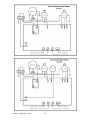
1
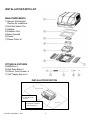
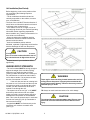
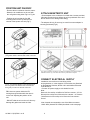
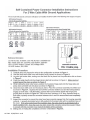
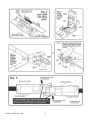
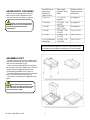
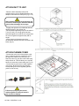
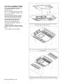
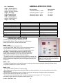
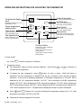
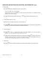
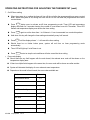
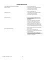
LITERATURE N U M B E R MPD 15000 Rooftop Air Conditioner for Recreational Vehicles Non-Ducted Models 574-206-9713 AC-1351 & AC-1501 •Installation •Operation •Maintenance Effective 12/03/2014 This air conditioner design has been certified by the Canadian Standards Association for installation in recreation vehicles. GENERAL INFORMATION I. PURPOSE SERVICE CALLS & QUESTIONS Location and phone numbers of qualified Service Centers can be found at our website http:/www.atwoodmobile.com or call This Atwood Air Command air conditioning unit is designed for installation on the roof of a recreational vehicle to provide cooling with AC-1351 models and cooling/heating with AC-1501 models. -The roof must be capable of supporting the weight of the unit which is 86lbs (39Kg). -The absolute minimum thickness of the roof must not be less than 1 inch (25mm). -Roof thicknesses between 5.0-6.5 inches (125-165mm) require extra-long hold down bolts Atwood PN 15086. -Trimming of the ductwork and/or bolts may be necessary depending on the roof thickness It is important that the unit is installed properly and according to the recommended guidelines. 866-869-3116 to locate a Service Center. WARNING: It is important that this installation manual is read and understood before installation. The unit must be installed by a qualified service technician. Failure to properly install the unit or attempting to modify it in any way can be extremely hazardous and may result in property damage and personal injury and will void the warranty. II. ENSURING EFFECTIVE OPERATION The effectiveness of the air conditioner is dependent on several factors e.g. size and heat load of the vehicle. When an Atwood unit is installed Atwood assumes that the vehicle is well insulated with 1 inch (25mm) foam minimum in all walls and roof, that the windows are of moderate size (preferably double glazed) and the roof vents are airtight when closed. Other methods of reducing heat load include: -Closing all doors, hatches, windows and blinds -Position the vehicle so if porch is used, it will face the sun and protect the windows from direct radiation. -Turning off appliances that might increase the heat load -Ensuring the vehicle is parked in a shaded position. In periods of extreme high temperature it is recommended to start the air conditioner earlier in the morning to greatly improve its ability to cope with the expected high heat load. BEFORE INSTALLATION Ensure that the installation instructions have been properly read and understood. Installation must conform to Local wiring codes and regulations or, in the absence of local codes, the Standard on Recreational Vehicles, NFPA 1192. and National Electrical Code NFPA 70. DO NOT attempt to modify or add components to the installation procedure. This equipment must only be serviced by a licensed refrigeration mechanic to maintain warranty coverage. If your installation varies from the method outlined please contact Atwood Mobile Products, LLC for specialty advice. III. CONDENSATION In areas of high humidity, the humid air within the RV will cause “sweating” or condensation in parts of the unit as the humid warm air contacts the colder air discharge system. If this occurs please ensure the following: -Closing all doors, hatches, windows and blinds to limit the ingress of warm humid air - Avoid running the inside fan on LOW or AUTO in such conditions. Running the fan on HI fan speed will result in higher airflow and reduce the tendency to have condensation form. Atwood will not be held responsible for problems relating to incorrect or improper installation methods. AC IOM 12/03/2014 rev 8 1 INSTALLATION PARTS LIST MAIN COMPONENTS 1) Atwood AirCommand Rooftop Air conditioner 2) Roof Seal Gasket 2 Pcs 3) Adapter 4) Extension Duct 5) Brace Assembly 6) Plenum 7) Plenum Filters x2 FITTINGS & FIXTURES 8) M8 Bolts x 4 9) Hold Down Bars x 4 10) Plenum Cover Screws x 4 11) Self Tapping Screws x 6 INSTALLATION POSITION Minimum 1” clearance from side grilles to any obstruction Minimum 8” clearance from rear grilles to any vertical face, 4” to any 45 degree face. AC IOM 12/03/2014 rev 8 2 Unit Installation (Non-Ducted) Before beginning, mark out the position of the unit considering the following important requirements: - The air conditioner should be situated as centrally as possible on the vehicle, to ensure even air distribution. - The front of the unit MUST face the direction of travel; failure to follow this instruction will result in damage to the condenser fans. - If the vehicle is over 23’ in length, or has an unusually high heat load (see General Operating Information section regarding expectations about insulation etc.), Atwood recommends 2 or more units to cool effectively. - When considering the installation position remember to check for clearance around the plenum inside the vehicle. - Avoid an installation position where a bulkhead, cupboard or light fitting could interfere with the discharge air flow from the plenum. CAUTION It is important that the unit is never more than 5° from the horizontal and the rear of the unit should never be higher than the front. - Contact Atwood if your installation differs significantly. ASSESS ROOF STRENGTH - The roof members MUST be strong enough to support the weight of the unit 99 lbs (45kg) without any roof deflection that will cause “pooling” of water around the unit. Contact your RV manufacturer to confirm the max load the roof is able to handle. If in any doubt consider the use of an external “H” frame. If the roof does not have an existing hole one must be cut. Cut from the roof then use the roof hole as a guide to cut through the ceiling. Contact your RV manufacturer for the best method to cut through the roof. - The square hole in the roof (14” x 14”) MUST be boxed up with minimum 3/4 inch square timber to provide a structure strong enough to withstand the compression of the installation bolts. This is also to ensure that air in not drawn from the roof cavity (Fig 3 & 4). Remember to leave access for wiring. - Longitudinals MUST be fixed securely to the transverse roof members to transfer load (see Fig 3). AC IOM 12/03/2014 rev 8 WARNING There may be electrical wiring located between the roof and ceiling. Ensure that power is properly disconnected at the supply (mains and/or battery). Failure to do so may result in personal injury or death TIP: Always use crawl boards across the roof to avoid damage CAUTION The unit weights approximately 86lbs (39kg). Ensure a two person lift or use a mechanical hoist to avoid the risk of injury. 3 POSITION UNIT ON ROOF - Remove the air conditioner from the carton. - Mount the air conditioner on the roof with the roof gasket using either Fig 6 or Fig 6a. - Position the unit so that the four M8 mounting holes will line up with the four corners of the square roof hole (Fig 7). ATTACH ADAPTER TO UNIT - Screw adapter to the underside of unit with the 4 screws provided (this step can also be done before the unit is positioned on the roof but be careful not to damage while fitting) - The adapter will only fit one way, be careful to ensure adapter is correctly positioned (Fig 8). Fig 6- Preferred Method: Gently set the unit over the roof gasket which is attached and sealed to the roof. Fig 8: Shows positioning of adapter to be attached to underside of unit. Ensure adapter is mounted the correct way, screw holes will not line up if attached out of phase. CONNECT ELECTRICAL SUPPLY Fig 6a- An Alternate Method: First attach and seal the roof gasket to the bottom of the roof unit and then gently set unit over the hole in the roof. TIP: Have one person inside the RV looking through the hole while the other is on the roof adjusting the position of the unit. - DO NOT slide the unit on the roof, this may damage the gasket and result in leaks. AC IOM 12/03/2014 rev 8 Installation must conform to local wiring codes and regulations or, in the absence of local codes, the Standard on Recreational Vehicles, NFPA 1192. and National Electrical Code NFPA 70. - Connect AC power supply to wire leads from unit Note: Brown wire from rooftop unit to Black or Red from customer – AC Hot Blue wire from rooftop unit to White wire from customer – AC Common Yellow/Green wire from rooftop unit to Green wire from customer Ground Note: Atwood recommends the use of the Molex connector 19421-0001 (Atwood PN 15024) described on the next page. 4 AC IOM 12/03/2014 rev 8 5 AC IOM 12/03/2014 rev 8 6 ASSESS ROOF THICKNESS - Measure the roof thickness and consult the table across to check if adjustments to the hold down bolt and duct length are required. Failure to cut the duct properly can result in an incorrect seal which will adversely affect the unit’s performance Roof Thickness Inch (mm) – Include ‘H’ frame if used. 4.92 (125) 3.94 (100) 3.15 (80) 2.36 (60) 1.57 (40) 1.0 (25) (absolute minimum) Duct length required – Inch (mm) Hold down bolt length required – Inch (mm) 5.71 (145) as supplied 4.72 (120) - Cut .98 (25) 3.94 (100) – Cut1.77 (45) 3.15 (80) – Cut 2.56 (65) 2.36 (60) – Cut 3.35 (85) 1.57 (40) – Cut 3.94 (100) As supplied As supplied As supplied Cut 1.97 (50) Cut 2.76 (70) Cut 3.35 (85) Roof thicknesses between 5.0” and 6.5” require extra-long hold down bolts available as Atwood Service kit PN 15086 ASSEMBLE DUCT - Thread a hold down bar onto the M8 bolt and push the bolt almost all the way into the hole in each corner of the brace (Fig 9) - Leave a .40 inch gap between the hold down bar and the recess in the plastic brace. This will allow for easier engagement with the four corresponding threaded holes in the unit. - Turn the assembly over and add the extension duct to the top of the assembly (Fig 11). - Take care to avoid tearing or ripping the duct apart. When attaching the duct to the unit, take care to ensure it forms a tight and unbroken seal that doesn’t allow discharge air to escape. AC IOM 12/03/2014 rev 8 7 ATTACH DUCT TO UNIT - Raise the brace assembly and slip the extension duct over the outside diameter of the adapter underneath the rooftop unit. (Fig 11-12). When attaching the duct to the unit take care to ensure it forms a tight, unbroken seal that doesn’t allow discharge air to escape. - Engage and tighten the four M8 bolts with the threaded inserts in the rooftop unit. - Recommended tightening torque of the bolts is 7 N.m (5.2 lb-ft). As a rough guide the bolts should be tightened so that the unit compresses the roof seal gasket to approximately half its height. - As the bolts are tightened ensure that the hold down bars slot into their recesses in the brace (Fig 12). ATTACH PLENUM COVER - Connect the main cover of the plenum to the duct by attaching the blue suspension cord to the lug on the inside of the cover (Fig 13). Reach into the unit, grab the control cable plug and pull down to -This will allow you to use two hands to connect the control cable (see Fig 14). - Connect the key pad control cables together (see below). Be sure that the plug joins the corresponding wire colors together (yellow to yellow, red to red etc.) Failure to properly plug the control cables together correctly will result in loss of power to display. AC IOM 12/03/2014 rev 8 8 ATTACH PLENUM COVER - Secure the main plenum cover to the duct assembly with the 4 screws provided (Fig 15). TIP: It is important that these screws are not over tightened otherwise the plenum may crack. - Remove the filter elements by pulling them out of the plenum, and use the six self-tapping counter sunk screws to secure the covers edges to the vehicle ceiling (Fig 16). In some instances a very small pilot hole may need to be drilled to guide the screws into place. - Replace the return air filters by sliding them into the plenum until they click into place -Your installation is now complete. AC IOM 12/03/2014 rev 8 9 VERIFYING NORMAL OPERATION 1. Turn the power on at the circuit breaker 2. Press the ON/OFF button and press the MODE button to select FAN 3. Cycle through the LO, MED and HIGH fan speeds checking that all speeds run. 4. Set mode to COOL, adjust temp via up/down buttons to approx. 6°F (3°C) less than the display temp (ie. Room temp) compressor will start within three minutes. 5. Set mode to HEAT, similarly set temp to approx. 6°F (3°C) above display temp. Compressor will start within three minutes. After a few minutes the fan will start and warm air will be apparent. Note: Regardless of the mode selected there will always be at least a 3 minute delay before the compressor starts. MAINTENANCE I. Plenum Filters The plenum filters are the only parts that require routine maintenance. They must be cleaned periodically to ensure that they do not become clogged with dust and other particles and not covered by Warranty. To clean the two plenum filters, first remove them both from the plenum by pulling them out of the assembly. Fig 17 shows the plenum filter when removed. The state of the filters can be ascertained from its appearance, the filters are translucent, and if they appear clogged then they should be cleaned. Generally the filters can be cleaned sufficiently by tapping them together to shake loose the dust and particles trapped inside. WARNING Airborne particles can pose a health risk, particularly to young children and the elderly. Ensure that filters are cleaned in a safe and well ventilated area. If a more thorough cleaning is required then the filters can be washed out using warm soapy water. Care must be taken to avoid ripping the fabric. The filters should be cleaned every two weeks or more when in use. Prolonged use, higher concentrations of airborne particles, and various other factors may result in the filters needing to be cleaned more often. Replacement filters can be ordered directly from Atwood Mobile Products, LLC by calling 866-869-3118. II. Mounting Bolts Atwood suggests that the hold down bolts are initially checked for tightness within the first 3 months of installation, and thereafter every 12 months if the vehicle is in constant use. III. Storage The air conditioner should be run on a routine basis to ensure the components remain in working order. If the vehicle is in storage or is to remain unoccupied for an extended length of time it is recommended than the air conditioner is allowed to run uninterrupted for 20-30min once every six months. AC IOM 12/03/2014 rev 8 10 GENERAL SPECIFICATIONS Air – Conditioner Height - 12.8 inch (325mm) Width – 26.6 inch (675mm) Length - 38.4 inch ( 975mm) Weight – 99 lb (45kg) Air Discharge Plenum Height - 2.6 inch (65mm) Width - 21.0 inch (535mm) Length - 21.8 inch (555mm) Weight – 1.1 lb ( 2.4kg) AC Description 13.5K Non-Ducted AC – White 13.5K Non-Ducted AC – Black 15K Non-Ducted AC – W hite 15K Non-Ducted AC – Black Model 13500 Electrical Rating: Nominal Cooling Capacity: Nominal Heating Capacity: F.L.A. Cooling: F.L.A. Heating: Locked Rotor Amps: Refrigerant: Refrigerant: Total Installed Weight: 115V, 60Hz 13,500 BTU/Hr n/a 12.5 A n/a 63 A R410A 18 Oz (510 g) 84 lb (38 kg) Model Number AC-1351W AC-1351B AC-1501W AC-1501B Model 15000 115V, 60Hz 15,000 BTU/Hr 15,000 BTU/Hr 13.0 A 13.0 A 63 A R410A 24 Oz (670 g) 86 lb (39 kg) OPERATING INSTRUCTIONS - Turn the unit on by pressing the ON/OFF button once. - Press the MODE button to cycle through the five mode selections: COOL, FAN, HEAT, DRY, AUTO Cool/Heat modes. MODE – COOL - Cycle mode pushbutton to highlight COOL. - You may select HIGH, MED, LOW, or AUTO fan speeds by pressing the fan pushbutton. It is recommended that you choose Auto. - The desired room temperature or set point is normally displayed on the digital display. To adjust the set point, press the TEMP up or down pushbuttons. The compressor will have a delayed start (usually 3 minutes) before unit begins to cool. Note: Any interruption to the power supply will result in a delayed compressor start up. - To display the actual room temperature press the SLEEP pushbutton for 5 seconds and the room temperature will be displayed. After releasing the SLEEP pushbutton the display will revert back to displaying the set point temperature. Thermostat control module. A “cool only” model (AC-1351) will not have the furnace pushbutton on the display. MODE – FAN - For simply re-circulating air, choose the FAN mode. Choose any of the three fan speeds by pressing FAN button. Note: Temperature pushbuttons are invalid in FAN mode. MODE - HEAT - To heat, press MODE pushbutton to highlight HEAT. - Select desired set point temperature by pressing TEMP up or down pushbuttons. It is recommended that the AUTO fan speed be selected. - After the delay, the compressor will start. Usually the fan will stop and will not re-energize until the heat exchanger has warmed and then the fan will start to blow warm air. - The unit will heat in the heat pump mode in ambient temperatures above approx. 45°F. The furnace will automatically engage at ambient temperatures below approx. 45°F. AC IOM 12/03/2014 rev 8 11 OPERATING INSTRUCTIONS – Continued MODE - DRY - The DRY mode can provide mild dehumidification for room temperatures above the set point and when additional cooling is not required. - Press MODE pushbutton to highlight DRY. - Set the temperature to desired set point. Note: the fan speed is locked in LOW. - The compressor will cycle on and off at approximate intervals of 6 minutes to extract moisture from the air while not lowering the room air temperature - For humid room temperatures below the set point - a separate, specialty dehumidifier will be more effective. - The unit can provide no dehumidification if the room temperature is below 64°F (18°C). MODE – AUTO COOL/HEAT - This mode has an outdoor defrost mode (indicated by a flashing HEAT LED). During the outdoor defrost cycle, the MODE pushbutton is inactive. SLEEP FUNCTION - With the unit operating in heat or cool mode, press sleep pushbutton to highlight the sleep light. The unit over the next hour will automatically raise the set point by 2°F. Conversely in heat mode, the set point will be lowered 2°F. TIMER FUNCTION - The timer may be used to turn off the unit in the future (up to 24 hours) OR the timer may be used to turn on the unit up to 24 hours in the future. - Press TIMER pushbutton once and the display will flash. Within 3 seconds, press the timer pushbutton until you have set desired time into the future to turn unit off. A subsequent press of the timer pushbutton will allow the time to start the unit to be programmed. LOCK FUNCTION (key symbol) - This provides a means of locking in the mode and fan settings. To lock, press Temp Down pushbutton simultaneously with MODE pushbutton. Hold for 3 seconds and the lock indicator will light. To unlock, repeat above procedure. DISPLAY SETTING - To change readout from Celsius to Fahrenheit or vice versa: Press Temp Down pushbutton simultaneously with the Fan pushbutton. REMOTE CONTROL UNIT Many models have a remote control unit which can adjust the thermostat remotely. - The remote control has duplicated the thermostat input pushbuttons including: the ON/OFF pushbutton, TEMP UP/DOWN, FAN, MODE, SLEEP, and TIMER pushbuttons - LEDs in the thermostat control respond to a pushbutton actuation from the remote control unit in the same manner as it would respond to the pushbutton actuation on the thermostat control. - The remote control requires a CR2025 battery commonly available. AC IOM 12/03/2014 rev 8 12 OPERATING INSTRUCTIONS FOR ADJUSTING THE THERMOSTAT Infra red reception Temperature display area SENSOR To receive wireless handset sign al ON/OFF Display timer setting, set or ro om temperature in C or F Room temperature setting button Timer button TEMP Press to activate on/off timer programming mode TIMER AUTO HIGH MED LOW COOL DRY HEAT FAN FAN FURNACE MODE On/Off button Press once to start operation Press again to stop operation Mode button Press to select cool, dry, heat , fan, or auto operation mode SLEEP Sleep button Press once to select sleep mode Press again to cancel sleep mode Fan speed button Key lock Press to select auto, high, medium or low fan speed Furnace button This button is valid in heatpump + furnace model only Press once to select furnace as primary heating Press again to cancel furnace as primary heating 1. Power On/Off Press ON/OFF to start or stop the air conditioner. 2. Temperature setting The temperature setting is always normally displayed. Press Press or to decrease or increase the set temperature. To display the room temperature, press SLEEP button for 5sec or longer. While this button is depressed, the room temperature is displayed until the key is released. Given the lack of display characters - if the control is displaying temperature in Fahrenheit, temperatures of 100-109°F will be displayed as A0 –A9, temperatures between 110-119°F will be displayed as B0-B9, temperatures between 120-129°F will be displayed as C0-C9, temperatures between 130-139°F will be displayed as D0-D9, temperatures between 140-149°F will be displayed as E0-E9, and temperatures between 150159°F will be displayed as F0-F9. Temperatures are displayed normally in degrees Centigrade. Press and FAN together for 5 seconds will change the temperature setting from C to F. Valid temperature set range is 16C-30C or 60F-85F. Temperature setting is bypassed in Fan mode. AC IOM 12/03/2014 rev 8 13 OPERATING INSTRUCTIONS FOR ADJUSTING THE THERMOSTAT (cont) 3. Mode setting Press MODE button to change the operation mode as follow:- Cool→Dry→Heat→Fan→Auto Cool/Heat Heat and Auto mode is not available for cooling only model. Auto mode is not available for model where furnace is primary heating. Heat LED flashes during outdoor defrost cycle. MODE button press is invalid during this cycle. 4. Furnace setting (model 1511 only) This function is available in heat pump + furnace model only. FURNACE Press button to activate furnace as primary heating. Heat pump operation will be inhibited thereafter. Press the same button again to disable furnace function. 5. Fan speed setting Press FAN button to change the fan speed:Auto→High→Medium→Low. Auto fan setting is bypass in Fan mode. Fan speed setting is bypass in dry mode. When furnace is working as primary heat source in heat mode, pressing the fan off, display will show “FF” until button is released. Pressing FAN the fan continue running, display will show “F0” until button is released. FAN button for 5sec to turn button again for 5sec to let 6. Sleep setting Press SLEEP button to activate or deactivate sleep setting. Sleep is bypass in Fan and Dry mode. AC IOM 12/03/2014 rev 8 14 OPERATING INSTRUCTIONS FOR ADJUSTING THE THERMOSTAT (cont) 7. On/Off timer setting When the system is on, setting the timer will turn off the unit after the programmed hours were counted down. When the system is off, setting the timer will turn on the unit after the programmed hours were counted down. Press TIMER button once to activate on/off timer programming mode. Timer LED and temperature display area flash for 3 seconds showing the number of count down hours left. Thereafter, Timer LED flashes and temperature display area shows the timer setting. Press TIMER again to set the timer from 1 to 24 hours in 1 hour incremented in a round robin pattern. Hold down this key will change the timer setting automatically every half second. Press TIMER until the display shows “—“ will cancel the timer setting. Should there be no further button press, system will exit from on timer programming mode automatically. Timer LED will light up if on/off timer is set. Press ON/OFF to start or stop the air conditioner will also cancel the timer setting. 8. Error code display Should there be any fault happen with the main board, the relevant error code will be shown on the temperature display area. If there is multiple faults happen at the same time, the error code will be shown one after another. System will alternate the display of error code and room temperature. Depends on the model of main board, the error codes available are: Fault Error code Room sensor failure E1 Indoor coil sensor failure E2 Outdoor coil sensor failure E3 Insufficient of refrigerant E4 Compressor overload E5 Not used E6 Not used E7 Outdoor air sensor failure E8 Wall pad room sensor failure E9 AC IOM 12/03/2014 rev 8 15 TROUBLESHOOTING o o Control Pad will not illuminate when ON/OFF button is pressed o o o Unit does not cool o o Unit does not heat o o o o o Insufficient cooling capacity o o o AC IOM 12/03/2014 rev 8 16 Check circuit breaker is on Control cable may be unplugged between outside unit and inside fascia Check power supply to vehicle Check circuit breaker is on Control cable may be unplugged between outside unit and inside fascia Check power supply to vehicle Ensure mode has been switched to heat (check green LED) Thermostat set point must be above room temperature In very cold conditions the unit will take more time to start producing warm air The heat pump will only provide heat in ambient temperatures above approx. 45°F. The furnace must be used as primary heat source in ambient temperatures below 45°F. Note: The compressor has a 3 minute delay before starting Ensure return air filters are clean Operate the unit on high fan speed to obtain maximum capacity Ensure all windows, doors, skylights and hatches are closed and curtains/awnings used to reduce heat load, check for adequate insulation in roof & walls ATWOOD AIR CONDITIONER LIMITED WARRANTY Atwood Mobile Products warrants to the original owner and subject to the below mentioned conditions, that this product will be free of defects in material or workmanship for a period of two years from the original date of purchase. Atwood’s liability hereunder is limited to the replacement of the product, repair of the product, or replacement of the product with a reconditioned product at the discretion of the manufacturer. This warranty is void if the product has been damaged by accident, unreasonable use, neglect, tampering or other causes not arising from defects in material workmanship. This warranty extends to the original owner of the product only and is subject to the following conditions: 1. For a period of two years from the date of purchase, Atwood will replace the complete air conditioner if the coils and plumbing leaks due to corrosion. This warranty includes reasonable labor charges required to replace the complete air conditioner. 2. For two years from the date of purchase, Atwood will repair or replace any part defective in material or workmanship. This warranty includes reasonable labor charges, required to remove and replace the part. Service calls to customer’s location are not considered part of these charges and are, therefore, the responsibility of the owner. 3. This warranty does not cover items classified as normal maintenance such as cleaning and replacement of filters. 4. In the event of a warranty claim, the owner must contact, in advance, either an authorized Atwood Service Center or the Atwood Service Department. Warranty claim service must be performed at an authorized Atwood Service Center (can be found online @ www.atwoodmobile.com) or as approved by the Consumer Service Department, Atwood Mobile Products, 1120 North Main St., Elkhart, IN 46514 USA. Phone: (866-869-3116). 5. Return parts must be shipped to Atwood “Prepaid”. Credit for shipping costs will be included with the warranty claim. The defective parts become the property of Atwood Mobile Products and must be returned as directed by the Consumer Service Department, Atwood Mobile Products. 6. This warranty applies only if the unit is installed according to the installation instructions, by an authorized service technician provided and complies with local and state codes. 7. The warranty period on replacement parts is the unused portion of the original warranty period or ninety (90) days, whichever is greater. 8. Damage or failure resulting from misuse including failure to seek proper repair service, misapplication, alterations, and water damage are the owner’s responsibility. 9. Atwood does not assume responsibility for any loss of use of vehicle, loss of time, inconvenience, expense for gasoline, telephone, travel, lodging, loss or damage to personal property or revenues. Some states do not allow the exclusion or limitation of incidental or consequential damages, so the above limitations or exclusions may not apply to you. 10. Any implied warranties are limited to two (2) years. Some states do not allow limitations on how long an implied warranty lasts, so the above limitation may not apply to you. This warranty gives you specific legal rights and you may also have other rights which vary from state to state. 11. Replacement parts purchased outside of the original air conditioner warranty carries a 90 day warranty. This includes the part at no charge and reasonable labor charges to replace it. This Atwood AirCommand air conditioner is designed for use in recreational vehicles for the purpose of cooling the cabin as stated in the “data plate” attached to the air conditioner. Any other use, unless authorized in writing by the Atwood Engineering Department, voids this warranty. AC IOM 12/03/2014 rev 8 17 AC IOM 12/03/2014 rev 8 18