1
Reference Manual
00809-0100-4107, Rev BA
June 2013
Rosemount 2051 Pressure Transmitter
with HART® Revision 5 and 7 Selectable Protocol
www.rosemount.com
Rosemount 2051 Pressure Transmitter
Read this manual before working with the product. For personal and system safety, and for
optimum product performance, make sure you thoroughly understand the contents before
installing, using, or maintaining this product.
For technical assistance, contacts are listed below:
Customer Central
Technical support, quoting, and order-related questions.
United States - 1-800-999-9307 (7:00 am to 7:00 pm CST)
Asia Pacific- 65 777 8211
Europe/ Middle East/ Africa - 49 (8153) 9390
North American Response Center
Equipment service needs.
1-800-654-7768 (24 hours—includes Canada)
Outside of these areas, contact your local Emerson Process Management representative.
The products described in this document are NOT designed for nuclear-qualified applications. Using
non-nuclear qualified products in applications that require nuclear-qualified hardware or products
may cause inaccurate readings.
For information on Rosemount nuclear-qualified products, contact your local Emerson Process
Management Sales Representative.
www.rosemount.com
Reference Manual
Table of Contents
00809-0100-4107, Rev BA
June 2013
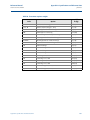
Contents
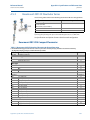
1Section 1: Introduction
1.1 Using this manual. . . . . . . . . . . . . . . . . . . . . . . . . . . . . . . . . . . . . . . . . . . . . . . . . . . . . . . 1
1.2 Models covered . . . . . . . . . . . . . . . . . . . . . . . . . . . . . . . . . . . . . . . . . . . . . . . . . . . . . . . . 2
1.2.1 Rosemount 2051C Coplanar™ Pressure Transmitter . . . . . . . . . . . . . . . . . . . 2
1.2.2 Rosemount 2051T in-line Pressure Transmitter . . . . . . . . . . . . . . . . . . . . . . . 2
1.2.3 Rosemount 2051L Level Transmitter . . . . . . . . . . . . . . . . . . . . . . . . . . . . . . . . 2
1.2.4 Rosemount 2051CF Series Flowmeter . . . . . . . . . . . . . . . . . . . . . . . . . . . . . . . 2
1.3 HART installation flowchart . . . . . . . . . . . . . . . . . . . . . . . . . . . . . . . . . . . . . . . . . . . . . . 3
1.4 Transmitter overview . . . . . . . . . . . . . . . . . . . . . . . . . . . . . . . . . . . . . . . . . . . . . . . . . . . 4
1.5 Service support. . . . . . . . . . . . . . . . . . . . . . . . . . . . . . . . . . . . . . . . . . . . . . . . . . . . . . . . . 5
1.6 Product recycling/ disposal . . . . . . . . . . . . . . . . . . . . . . . . . . . . . . . . . . . . . . . . . . . . . . 6
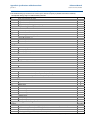
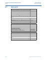
2Section 2: Configuration
2.1 Configuration overview. . . . . . . . . . . . . . . . . . . . . . . . . . . . . . . . . . . . . . . . . . . . . . . . . . 7
2.2 Safety messages . . . . . . . . . . . . . . . . . . . . . . . . . . . . . . . . . . . . . . . . . . . . . . . . . . . . . . . . 7
2.3 System readiness . . . . . . . . . . . . . . . . . . . . . . . . . . . . . . . . . . . . . . . . . . . . . . . . . . . . . . . 8
2.3.1 Confirm correct Device Driver . . . . . . . . . . . . . . . . . . . . . . . . . . . . . . . . . . . . . . 8
2.4 Configuration basics . . . . . . . . . . . . . . . . . . . . . . . . . . . . . . . . . . . . . . . . . . . . . . . . . . . . 9
2.4.1 Configuring on the bench . . . . . . . . . . . . . . . . . . . . . . . . . . . . . . . . . . . . . . . . . . 9
2.4.2 Configuration tools . . . . . . . . . . . . . . . . . . . . . . . . . . . . . . . . . . . . . . . . . . . . . .10
2.4.3 Setting the loop to manual . . . . . . . . . . . . . . . . . . . . . . . . . . . . . . . . . . . . . . . .12
2.5 Verify configuration. . . . . . . . . . . . . . . . . . . . . . . . . . . . . . . . . . . . . . . . . . . . . . . . . . . .12
2.5.1 Verifying configuration with Field Communicator . . . . . . . . . . . . . . . . . . . .12
2.5.2 Verifying configuration with AMS Device Manager . . . . . . . . . . . . . . . . . . .13
2.5.3 Verifying configuration with Local Operator Interface . . . . . . . . . . . . . . . .13
2.5.4 Verifying process variables configuration . . . . . . . . . . . . . . . . . . . . . . . . . . .13
2.6 Basic setup of the transmitter . . . . . . . . . . . . . . . . . . . . . . . . . . . . . . . . . . . . . . . . . . .14
2.6.1 Setting pressure units . . . . . . . . . . . . . . . . . . . . . . . . . . . . . . . . . . . . . . . . . . . .14
2.6.2 Setting transmitter output (Transfer Function) . . . . . . . . . . . . . . . . . . . . . .14
2.6.3 Rerange the transmitter . . . . . . . . . . . . . . . . . . . . . . . . . . . . . . . . . . . . . . . . . .16
2.6.4 Damping. . . . . . . . . . . . . . . . . . . . . . . . . . . . . . . . . . . . . . . . . . . . . . . . . . . . . . . .19
2.7 Configuring the LCD Display . . . . . . . . . . . . . . . . . . . . . . . . . . . . . . . . . . . . . . . . . . . .20
2.8 Detailed transmitter setup . . . . . . . . . . . . . . . . . . . . . . . . . . . . . . . . . . . . . . . . . . . . . .21
2.8.1 Configuring alarm and saturation levels. . . . . . . . . . . . . . . . . . . . . . . . . . . . .21
Table of Contents
1
Reference Manual
Table of Contents
00809-0100-4107, Rev BA
June 2013
2.8.2 Configuring Scaled Variable . . . . . . . . . . . . . . . . . . . . . . . . . . . . . . . . . . . . . . .22
2.8.3 Re-Mapping device variables . . . . . . . . . . . . . . . . . . . . . . . . . . . . . . . . . . . . . .25
2.9 Performing transmitter tests . . . . . . . . . . . . . . . . . . . . . . . . . . . . . . . . . . . . . . . . . . . .27
2.9.1 Verifying alarm level. . . . . . . . . . . . . . . . . . . . . . . . . . . . . . . . . . . . . . . . . . . . . .27
2.9.2 Performing an Analog Loop Test . . . . . . . . . . . . . . . . . . . . . . . . . . . . . . . . . . .27
2.9.3 Simulate Device Variables . . . . . . . . . . . . . . . . . . . . . . . . . . . . . . . . . . . . . . . . .28
2.10Configuring burst mode . . . . . . . . . . . . . . . . . . . . . . . . . . . . . . . . . . . . . . . . . . . . . . . .29
2.11Establishing multidrop communication . . . . . . . . . . . . . . . . . . . . . . . . . . . . . . . . . .30
2.11.1Changing a transmitter address . . . . . . . . . . . . . . . . . . . . . . . . . . . . . . . . . . .31
2.11.2Communicating with a multidropped transmitter. . . . . . . . . . . . . . . . . . . .32
3Section 3: Hardware Installation
3.1 Overview . . . . . . . . . . . . . . . . . . . . . . . . . . . . . . . . . . . . . . . . . . . . . . . . . . . . . . . . . . . . .33
3.2 Safety messages . . . . . . . . . . . . . . . . . . . . . . . . . . . . . . . . . . . . . . . . . . . . . . . . . . . . . . .33
3.3 Considerations . . . . . . . . . . . . . . . . . . . . . . . . . . . . . . . . . . . . . . . . . . . . . . . . . . . . . . . .34
3.3.1 Installation considerations . . . . . . . . . . . . . . . . . . . . . . . . . . . . . . . . . . . . . . . .34
3.3.2 Environmental considerations . . . . . . . . . . . . . . . . . . . . . . . . . . . . . . . . . . . . .34
3.3.3 Mechanical considerations . . . . . . . . . . . . . . . . . . . . . . . . . . . . . . . . . . . . . . . .35
3.4 Installation procedures . . . . . . . . . . . . . . . . . . . . . . . . . . . . . . . . . . . . . . . . . . . . . . . . .35
3.4.1 Mount the transmitter . . . . . . . . . . . . . . . . . . . . . . . . . . . . . . . . . . . . . . . . . . . .35
3.4.2 Impulse piping. . . . . . . . . . . . . . . . . . . . . . . . . . . . . . . . . . . . . . . . . . . . . . . . . . .42
3.4.3 Process connections. . . . . . . . . . . . . . . . . . . . . . . . . . . . . . . . . . . . . . . . . . . . . .44
3.4.4 Inline process connection . . . . . . . . . . . . . . . . . . . . . . . . . . . . . . . . . . . . . . . . .45
3.5 Rosemount 305, 306, and 304 Manifolds . . . . . . . . . . . . . . . . . . . . . . . . . . . . . . . . .47
3.5.1 Rosemount 305 Integral Manifold installation procedure . . . . . . . . . . . . .48
3.5.2 Rosemount 306 Integral Manifold installation procedure . . . . . . . . . . . . .48
3.5.3 Rosemount 304 Conventional Manifold installation procedure . . . . . . . .49
3.5.4 Manifold operation. . . . . . . . . . . . . . . . . . . . . . . . . . . . . . . . . . . . . . . . . . . . . . .49
4Section 4: Electrical Installation
4.1 Overview . . . . . . . . . . . . . . . . . . . . . . . . . . . . . . . . . . . . . . . . . . . . . . . . . . . . . . . . . . . . .53
4.2 Safety messages . . . . . . . . . . . . . . . . . . . . . . . . . . . . . . . . . . . . . . . . . . . . . . . . . . . . . . .53
4.3 LCD/LOI Display . . . . . . . . . . . . . . . . . . . . . . . . . . . . . . . . . . . . . . . . . . . . . . . . . . . . . . .54
4.3.1 Rotating LCD/LOI Display . . . . . . . . . . . . . . . . . . . . . . . . . . . . . . . . . . . . . . . . .54
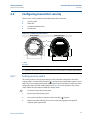
4.4 Configuring transmitter security. . . . . . . . . . . . . . . . . . . . . . . . . . . . . . . . . . . . . . . . .55
4.4.1 Setting security switch. . . . . . . . . . . . . . . . . . . . . . . . . . . . . . . . . . . . . . . . . . . .55
4.4.2 HART Lock . . . . . . . . . . . . . . . . . . . . . . . . . . . . . . . . . . . . . . . . . . . . . . . . . . . . . .56
2
Table of Contents
Reference Manual
Table of Contents
00809-0100-4107, Rev BA
June 2013
4.4.3 Configuration Button lock. . . . . . . . . . . . . . . . . . . . . . . . . . . . . . . . . . . . . . . . .56
4.4.4 Local Operator Interface Password . . . . . . . . . . . . . . . . . . . . . . . . . . . . . . . . .57
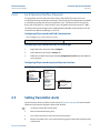
4.5 Setting Transmitter alarm . . . . . . . . . . . . . . . . . . . . . . . . . . . . . . . . . . . . . . . . . . . . . .57
4.6 Electrical considerations . . . . . . . . . . . . . . . . . . . . . . . . . . . . . . . . . . . . . . . . . . . . . . . .58
4.6.1 Conduit installation . . . . . . . . . . . . . . . . . . . . . . . . . . . . . . . . . . . . . . . . . . . . . .58
4.6.2 Power supply . . . . . . . . . . . . . . . . . . . . . . . . . . . . . . . . . . . . . . . . . . . . . . . . . . . .59
4.6.3 Wiring the transmitter . . . . . . . . . . . . . . . . . . . . . . . . . . . . . . . . . . . . . . . . . . . .59
4.6.4 Grounding the transmitter . . . . . . . . . . . . . . . . . . . . . . . . . . . . . . . . . . . . . . . .61
5Section 5: Operation and Maintenance
5.1 Overview . . . . . . . . . . . . . . . . . . . . . . . . . . . . . . . . . . . . . . . . . . . . . . . . . . . . . . . . . . . . .65
5.2 Safety messages . . . . . . . . . . . . . . . . . . . . . . . . . . . . . . . . . . . . . . . . . . . . . . . . . . . . . . .65
5.2.1 Warnings . . . . . . . . . . . . . . . . . . . . . . . . . . . . . . . . . . . . . . . . . . . . . . . . . . . . . . .65
5.3 Recommended calibration tasks. . . . . . . . . . . . . . . . . . . . . . . . . . . . . . . . . . . . . . . . .66
5.4 Calibration overview . . . . . . . . . . . . . . . . . . . . . . . . . . . . . . . . . . . . . . . . . . . . . . . . . . .66
5.4.1 Determining necessary Sensor Trims . . . . . . . . . . . . . . . . . . . . . . . . . . . . . . .67
5.4.2 Determining calibration frequency . . . . . . . . . . . . . . . . . . . . . . . . . . . . . . . . .68
5.4.3 Compensating for Span line pressure effects (range 4 and range 5). . . . .70
5.5 Trim the pressure signal . . . . . . . . . . . . . . . . . . . . . . . . . . . . . . . . . . . . . . . . . . . . . . . .71
5.5.1 Sensor Trim overview. . . . . . . . . . . . . . . . . . . . . . . . . . . . . . . . . . . . . . . . . . . . .71
5.5.2 Perform a Sensor Trim . . . . . . . . . . . . . . . . . . . . . . . . . . . . . . . . . . . . . . . . . . . .72
5.5.3 Recall Factory Trim—sensor trim . . . . . . . . . . . . . . . . . . . . . . . . . . . . . . . . . . .73
5.6 Trim the analog output . . . . . . . . . . . . . . . . . . . . . . . . . . . . . . . . . . . . . . . . . . . . . . . . .74
5.6.1 Performing Digital-to-Analog Trim (4-20mA/ 1-5 V Output Trim) . . . . . .75
5.6.2 Performing Digital-to-Analog Trim (4-20mA/ 1-5 V Output Trim) using other
scale76
5.6.3 Recalling Factory Trim—analog output. . . . . . . . . . . . . . . . . . . . . . . . . . . . . .77
5.7 Switching HART Revision . . . . . . . . . . . . . . . . . . . . . . . . . . . . . . . . . . . . . . . . . . . . . . .78
5.7.1 Switching HART revision with Generic Menu. . . . . . . . . . . . . . . . . . . . . . . . .78
5.7.2 Switching HART Revision with Field Communicator . . . . . . . . . . . . . . . . . .78
5.7.3 Switching HART Revision with AMS Device Manager. . . . . . . . . . . . . . . . . .78
5.7.4 Switching HART revision with Local Operator Interface . . . . . . . . . . . . . . .78
6Section 6: Troubleshooting
6.1 Overview . . . . . . . . . . . . . . . . . . . . . . . . . . . . . . . . . . . . . . . . . . . . . . . . . . . . . . . . . . . . .81
6.2 Safety messages . . . . . . . . . . . . . . . . . . . . . . . . . . . . . . . . . . . . . . . . . . . . . . . . . . . . . . .81
6.2.1 Warnings . . . . . . . . . . . . . . . . . . . . . . . . . . . . . . . . . . . . . . . . . . . . . . . . . . . . . . .82
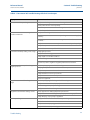
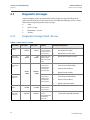
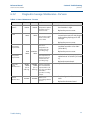
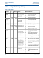
6.3 Diagnostic messages. . . . . . . . . . . . . . . . . . . . . . . . . . . . . . . . . . . . . . . . . . . . . . . . . . .84
Table of Contents
3
Reference Manual
Table of Contents
00809-0100-4107, Rev BA
June 2013
6.3.1 Diagnostic message: failed - fix now . . . . . . . . . . . . . . . . . . . . . . . . . . . . . . . .84
6.3.2 Diagnostic message: Maintenance - Fix Soon . . . . . . . . . . . . . . . . . . . . . . . .85
6.3.3 Diagnostic message: Advisory . . . . . . . . . . . . . . . . . . . . . . . . . . . . . . . . . . . . .86
6.4 Disassembly procedures . . . . . . . . . . . . . . . . . . . . . . . . . . . . . . . . . . . . . . . . . . . . . . . .87
6.4.1 Removing from service . . . . . . . . . . . . . . . . . . . . . . . . . . . . . . . . . . . . . . . . . . .87
6.4.2 Removing terminal block . . . . . . . . . . . . . . . . . . . . . . . . . . . . . . . . . . . . . . . . .88
6.4.3 Removing the electronics board . . . . . . . . . . . . . . . . . . . . . . . . . . . . . . . . . . .88
6.4.4 Removing sensor module from the electronics housing . . . . . . . . . . . . . . .88
6.5 Reassembly procedures . . . . . . . . . . . . . . . . . . . . . . . . . . . . . . . . . . . . . . . . . . . . . . . .89
6.5.1 Attaching electronics board . . . . . . . . . . . . . . . . . . . . . . . . . . . . . . . . . . . . . . .89
6.5.2 Installing terminal block . . . . . . . . . . . . . . . . . . . . . . . . . . . . . . . . . . . . . . . . . .90
6.5.3 Reassembling the Rosemount 2051C process flange . . . . . . . . . . . . . . . . .90
6.5.4 Installing drain/vent valve . . . . . . . . . . . . . . . . . . . . . . . . . . . . . . . . . . . . . . . . .91
7Section 7: Safety Instrumented Systems Requirements
7.1 Safety Instrumented Systems (SIS) Certification . . . . . . . . . . . . . . . . . . . . . . . . . . .93
7.1.1 Rosemount 2051 safety certified identification . . . . . . . . . . . . . . . . . . . . . .93
7.1.2 Installation in SIS applications . . . . . . . . . . . . . . . . . . . . . . . . . . . . . . . . . . . . .93
7.1.3 Configuring in SIS applications. . . . . . . . . . . . . . . . . . . . . . . . . . . . . . . . . . . . .94
7.1.4 Rosemount 2051 SIS operation and mainenance. . . . . . . . . . . . . . . . . . . . .95
7.1.5 Inspection. . . . . . . . . . . . . . . . . . . . . . . . . . . . . . . . . . . . . . . . . . . . . . . . . . . . . . .96
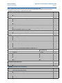
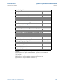
AAppendix A: Specifications and Reference Data
A.1 Performance specifications . . . . . . . . . . . . . . . . . . . . . . . . . . . . . . . . . . . . . . . . . . . . .99
A.1.1 Conformance to specification (±3s (Sigma)) . . . . . . . . . . . . . . . . . . . . . . . . .99
A.1.2 Reference accuracy . . . . . . . . . . . . . . . . . . . . . . . . . . . . . . . . . . . . . . . . . . . . . .99
A.1.3 Flow performance - flow reference accuracy. . . . . . . . . . . . . . . . . . . . . . . 100
A.1.4 Long term stability . . . . . . . . . . . . . . . . . . . . . . . . . . . . . . . . . . . . . . . . . . . . . 101
A.1.5 Dynamic performance . . . . . . . . . . . . . . . . . . . . . . . . . . . . . . . . . . . . . . . . . . 101
A.1.6 Line pressure effect per 1000 psi (6,9 MPa) . . . . . . . . . . . . . . . . . . . . . . . . 101
A.1.7 Ambient temperature effect per 50 °F (28 °C). . . . . . . . . . . . . . . . . . . . . . 102
A.1.8 Mounting position effects . . . . . . . . . . . . . . . . . . . . . . . . . . . . . . . . . . . . . . . 102
A.1.9 Vibration effect . . . . . . . . . . . . . . . . . . . . . . . . . . . . . . . . . . . . . . . . . . . . . . . . 102
A.1.10Power supply effect . . . . . . . . . . . . . . . . . . . . . . . . . . . . . . . . . . . . . . . . . . . . 102
A.1.11Electromagnetic compatibility (EMC) . . . . . . . . . . . . . . . . . . . . . . . . . . . . 102
A.1.12Transient protection (option code T1) . . . . . . . . . . . . . . . . . . . . . . . . . . . . 102
A.2 Functional specifications . . . . . . . . . . . . . . . . . . . . . . . . . . . . . . . . . . . . . . . . . . . . . 103
4
Table of Contents
Reference Manual
Table of Contents
00809-0100-4107, Rev BA
June 2013
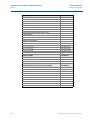
A.2.1 Service. . . . . . . . . . . . . . . . . . . . . . . . . . . . . . . . . . . . . . . . . . . . . . . . . . . . . . . . 103
A.2.2 Range and sensor limits. . . . . . . . . . . . . . . . . . . . . . . . . . . . . . . . . . . . . . . . . 103
A.2.3 4–20 mA (output code A) . . . . . . . . . . . . . . . . . . . . . . . . . . . . . . . . . . . . . . . 104
A.2.4 HART 1-5 Vdc Low Power (Output Code M). . . . . . . . . . . . . . . . . . . . . . . . 105
A.2.5 Overpressure Limits . . . . . . . . . . . . . . . . . . . . . . . . . . . . . . . . . . . . . . . . . . . . 106
A.2.6 Static pressure limit . . . . . . . . . . . . . . . . . . . . . . . . . . . . . . . . . . . . . . . . . . . . 106
A.2.7 Burst pressure limits. . . . . . . . . . . . . . . . . . . . . . . . . . . . . . . . . . . . . . . . . . . . 107
A.2.8 Failure mode alarm. . . . . . . . . . . . . . . . . . . . . . . . . . . . . . . . . . . . . . . . . . . . . 107
A.2.9 Temperature limits. . . . . . . . . . . . . . . . . . . . . . . . . . . . . . . . . . . . . . . . . . . . . 107
A.2.10Humidity limits . . . . . . . . . . . . . . . . . . . . . . . . . . . . . . . . . . . . . . . . . . . . . . . . 108
A.2.11Turn-on time . . . . . . . . . . . . . . . . . . . . . . . . . . . . . . . . . . . . . . . . . . . . . . . . . . 108
A.2.12Volumetric displacement . . . . . . . . . . . . . . . . . . . . . . . . . . . . . . . . . . . . . . . 108
A.2.13Damping . . . . . . . . . . . . . . . . . . . . . . . . . . . . . . . . . . . . . . . . . . . . . . . . . . . . . 109
A.3 Physical specifications . . . . . . . . . . . . . . . . . . . . . . . . . . . . . . . . . . . . . . . . . . . . . . . . 109
A.3.1 Electrical connections . . . . . . . . . . . . . . . . . . . . . . . . . . . . . . . . . . . . . . . . . . 109
A.3.2 Process connections. . . . . . . . . . . . . . . . . . . . . . . . . . . . . . . . . . . . . . . . . . . . 109
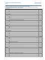
A.3.3 Process-wetted parts . . . . . . . . . . . . . . . . . . . . . . . . . . . . . . . . . . . . . . . . . . . 110
A.3.4 Rosemount 2051L process wetted parts . . . . . . . . . . . . . . . . . . . . . . . . . . 110
A.3.5 Non-wetted parts . . . . . . . . . . . . . . . . . . . . . . . . . . . . . . . . . . . . . . . . . . . . . . 111
A.3.6 Shipping weights . . . . . . . . . . . . . . . . . . . . . . . . . . . . . . . . . . . . . . . . . . . . . . 112
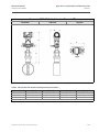
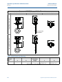
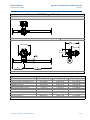
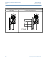
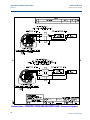
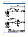
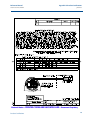
A.4 Dimensional drawings. . . . . . . . . . . . . . . . . . . . . . . . . . . . . . . . . . . . . . . . . . . . . . . . 113
A.5 Ordering Information . . . . . . . . . . . . . . . . . . . . . . . . . . . . . . . . . . . . . . . . . . . . . . . . 125
A.5.1 Rosemount 2051C Coplanar Pressure Transmitter . . . . . . . . . . . . . . . . . 125
A.5.2 Rosemount 2051T In-Line Pressure Transmitter. . . . . . . . . . . . . . . . . . . . 132
A.5.3 Rosemount 2051CF Flowmeter Series . . . . . . . . . . . . . . . . . . . . . . . . . . . . 137
A.5.4 Rosemount 2051L Level Transmitter . . . . . . . . . . . . . . . . . . . . . . . . . . . . . 153
A.6 Options . . . . . . . . . . . . . . . . . . . . . . . . . . . . . . . . . . . . . . . . . . . . . . . . . . . . . . . . . . . . 159
A.7 Spare parts. . . . . . . . . . . . . . . . . . . . . . . . . . . . . . . . . . . . . . . . . . . . . . . . . . . . . . . . . . 164
BAppendix B: Product Certifications
B.1 Approved Manufacturing Locations . . . . . . . . . . . . . . . . . . . . . . . . . . . . . . . . . . . . 169
B.2 European Directive Information . . . . . . . . . . . . . . . . . . . . . . . . . . . . . . . . . . . . . . . 169
B.2.1 Ordinary Location Certification for Factory Mutual . . . . . . . . . . . . . . . . . 169
B.3 HART Protocol. . . . . . . . . . . . . . . . . . . . . . . . . . . . . . . . . . . . . . . . . . . . . . . . . . . . . . . 170
B.3.1 Hazardous Locations Certifications . . . . . . . . . . . . . . . . . . . . . . . . . . . . . . . 170
B.4 Foundation fieldbus and Profibus PA protocols . . . . . . . . . . . . . . . . . . . . . . . . . . 175
B.4.1 Hazardous Locations Certifications . . . . . . . . . . . . . . . . . . . . . . . . . . . . . . . 175
Table of Contents
5
Reference Manual
Table of Contents
00809-0100-4107, Rev BA
June 2013
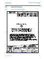
B.5 Approval drawings . . . . . . . . . . . . . . . . . . . . . . . . . . . . . . . . . . . . . . . . . . . . . . . . . . . 181
B.5.1 Factory mutual 02051-1009. . . . . . . . . . . . . . . . . . . . . . . . . . . . . . . . . . . . . 181
B.5.2 Canadian standards association (CSA) 02051-1008 . . . . . . . . . . . . . . . . 194
CAppendix C: Field Communicator Menu Trees and Fast Keys
C.1 Field Communicator menu trees. . . . . . . . . . . . . . . . . . . . . . . . . . . . . . . . . . . . . . . 205
C.2 Field Communicator fast keys . . . . . . . . . . . . . . . . . . . . . . . . . . . . . . . . . . . . . . . . . 210
DAppendix D: Local Operator Interface
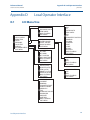
D.1 LOI Menu Tree. . . . . . . . . . . . . . . . . . . . . . . . . . . . . . . . . . . . . . . . . . . . . . . . . . . . . . . 211
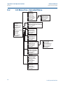
D.2 LOI Menu Tree - Extended Menu . . . . . . . . . . . . . . . . . . . . . . . . . . . . . . . . . . . . . . . 212
D.3 Number entry . . . . . . . . . . . . . . . . . . . . . . . . . . . . . . . . . . . . . . . . . . . . . . . . . . . . . . . 213
D.4 Text entry. . . . . . . . . . . . . . . . . . . . . . . . . . . . . . . . . . . . . . . . . . . . . . . . . . . . . . . . . . . 214
6
Table of Contents
Section 1: Introduction
Reference Manual
June 2013
00809-0100-4107, Rev BA
Section 1
Introduction
Using this manual . . . . . . . . . . . . . . . . . . . . . . . . . . . . . . . . . . . . . . . . . . . . . . . . . . . . . . . . page 1
Models covered . . . . . . . . . . . . . . . . . . . . . . . . . . . . . . . . . . . . . . . . . . . . . . . . . . . . . . . . . . page 2
HART installation flowchart . . . . . . . . . . . . . . . . . . . . . . . . . . . . . . . . . . . . . . . . . . . . . . . page 3
Transmitter overview . . . . . . . . . . . . . . . . . . . . . . . . . . . . . . . . . . . . . . . . . . . . . . . . . . . . page 4
Service support . . . . . . . . . . . . . . . . . . . . . . . . . . . . . . . . . . . . . . . . . . . . . . . . . . . . . . . . . . page 5
Product recycling/ disposal . . . . . . . . . . . . . . . . . . . . . . . . . . . . . . . . . . . . . . . . . . . . . . . page 6
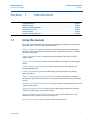
1.1
Using this manual
The sections in this manual provide information on installing, operating, and maintaining the
Rosemount 2051. The sections are organized as follows:
Section 2: Configuration provides instruction on commissioning and operating Rosemount
2051 Transmitters. Information on software functions, configuration parameters, and online
variables is also included.
Section 3: Hardware Installation contains mechanical installation instructions, and field
upgrade options.
Section 4: Electrical Installation contains electrical installation instructions, and field upgrade
options.
Section 5: Operation and Maintenance provides detailed information on calibrating and
changing HART Revisions.
Section 6: Troubleshooting provides troubleshooting techniques for the most common
operating problems.
Section 7: Safety Instrumented Systems Requirements provides identification, installation,
configuration, operation and maintenance, and inspection information for Safety Intrumented
Systems.
Appendix A: Specifications and Reference Data supplies reference and specification data, as well
as ordering information.
Appendix B: Product Certifications contains intrinsic safety approval information, European
ATEX directive information, and approval drawings.
Appendix C: Field Communicator Menu Trees and Fast Keys provides full menu trees and
abbreviated fast key sequences for commissioning tasks.
Appendix D: Local Operator Interface provides detailed LOI menu trees.
Introduction
1
Reference Manual
Section 1: Introduction
00809-0100-4107, Rev BA
June 2013
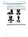
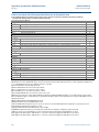
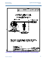
1.2
Models covered
The following Rosemount 2051 Pressure Transmitters are covered by this manual:
1.2.1
Rosemount 2051C Coplanar™ Pressure Transmitter
1.2.2
Rosemount 2051T in-line Pressure Transmitter
1.2.3
Measures gage/absolute pressure up to 10000 psi (689,5 bar).
Rosemount 2051L Level Transmitter
1.2.4
Measures differential and gage pressure up to 2000 psi (137,9 bar).
Measures level and specific gravity up to 300 psi (20,7 bar).
Rosemount 2051CF Series Flowmeter
Measures flow in line sizes from 1/2-in. (15mm) to 96-in. (2400 mm).
Note
For Rosemount 2051 with FOUNDATION™ Fieldbus, see Rosemount Product Manual
00809-0200-4101. For Rosemount 2051 with Profibus PA, see Rosemount Product Manual
00809-0300-4101.
2
Introduction
Reference Manual
Section 1: Introduction
00809-0100-4107, Rev BA
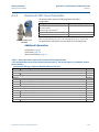
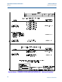
1.3
June 2013
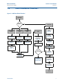
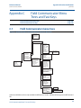
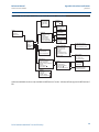
HART installation flowchart
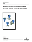
Figure 1-1. HART installation flowchart
START HERE
Bench
Calibration?
No
Field Install
Yes
Configure for
Pressure
Configure for
Level
Configure for
Flow
Set Units
(page 13)
Configure
Scaled Variable
(page 23)
Configure
Scaled Variable
(page 23)
Set Range
Points
(page 15)
Set Scaled
Variable to PV
(page 23)
Set Scaled
Variable to PV
(page 26)
Configure
Security and
Alarm
(page 59)
Verify
Mount
Transmitter
(page 40)
Review
Transmitter
Configuration
(page 12)
Check Process
Connection
(page 48)
Apply Pressure
Wire Transmitter
(page 63)
Select Linear
Output
(page 14)
Within
Specifications?
Set Damping
(page 19)
Yes
Power
Transmitter
(page 63)
No
Refer to
Section 5:
Operation and
Maintenance
Confirm
Transmitter
Configuration
(page 12)
Trim the
Transmitter
(page 74)
Done
Introduction
3
Reference Manual
Section 1: Introduction
00809-0100-4107, Rev BA
June 2013
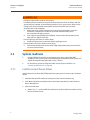
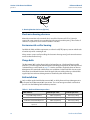
1.4
Transmitter overview
The Rosemount 2051C Coplanar design is offered for Differential Pressure (DP) and Gage
Pressure (GP) measurements. The Rosemount 2051C utilizes capacitance sensor technology for
DP and GP measurements. The Rosemount 2051T utilizes piezoresistive sensor technology for
AP and GP measurements.
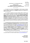
The major components of the Rosemount 2051 are the sensor module and the electronics
housing. The sensor module contains the oil filled sensor system (isolating diaphragms, oil fill
system, and sensor) and the sensor electronics. The sensor electronics are installed within the
sensor module and include a temperature sensor, a memory module, and the analog to digital
signal converter (A/D converter). The electrical signals from the sensor module are transmitted
to the output electronics in the electronics housing. The electronics housing contains the
output electronics board, the optional external configuration buttons, and the terminal block.
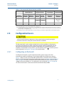
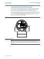
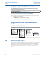
The basic block diagram of the Rosemount 2051CD is illustrated in Figure 1-3 on page 5.
For the Rosemount 2051, pressure is applied to the isolating diaphragm(s). The oil deflects the
sensor which then changes its capacitance or voltage signal. This signal is then changed to a
digital signal by the Signal Processing. The microprocessor then takes the signals from the
Signal Processing and calculates the correct output of the transmitter. This signal is then sent to
the D/A converter, which converts the signal back to the analog signal, then superimposes the
HART signal on the 4-20 mA output.
An optional LCD can be ordered that connects directly to the interface board which maintains
direct access to the signal terminals. The display indicates output and abbreviated diagnostic
messages. A glass display cover is provided. For 4-20 mA HART output, the LCD Display features
a two-line display. The first line displays the actual measured value, the second line of six
characters displays the engineering units. The LCD can also display diagnostic messages.
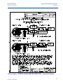
Note
LCD Display utilizes a 5x6 character display and can display output and diagnostic messages. The
LOI Display uses an 8x6 character display and can display output, diagnostic messages, and LOI
menu screens. The LOI Display comes with 2 buttons mounted on the front of the display board.
See Figure 1-2.
Figure 1-2. LCD/LOI Display
LCD Display
4
LOI Display
Introduction
Reference Manual
Section 1: Introduction
00809-0100-4107, Rev BA
June 2013
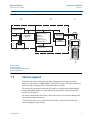
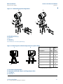
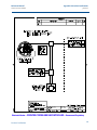
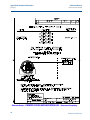
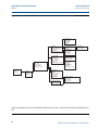
Figure 1-3. Block diagram of operation
A
B
C
Signal Processing
Microprocessor
Temp.
Sensor
Sensor Module
Memory
Sensor linearization
Rerange
Damping
Diagnostics
Engineering units
Communication
Digital-toAnalog Signal
Conversion
Digital
Communication
Memory
Configuration
D
A. Sensor Module
B. Electronics Board
C. 4-20 mA Signal to Control System
D. Field Communicator
1.5
Service support
Within the United States, call the Emerson Process Management Instrument and Valve
Response Center using the 1-800-654-RSMT (7768) toll-free number. This center, available 24
hours a day, will assist you with any needed information or materials.
The center will ask for product model and serial numbers, and will provide a Return Material
Authorization (RMA) number. The center will also ask for the process material to which the
product was last exposed.
For inquiries outside of the United States, contact the nearest Emerson Process Management
representative for RMA instructions.
To expedite the return process outside of the United States, contact the nearest Emerson
Process Management representative.
Introduction
5
Section 1: Introduction
Reference Manual
00809-0100-4107, Rev BA
June 2013
Individuals who handle products exposed to a hazardous substance can avoid injury if they
are informed of and understand the hazard. The product being returned will require a copy
of the required Material Safety Data Sheet (MSDS) for each substance must be included
with the returned goods.
Emerson Process Management Instrument and Valve Response Center representatives will
explain the additional information and procedures necessary to return goods exposed to
hazardous substances.
1.6
Product recycling/ disposal
Recycling of equipment and packaging should be taken into consideration and disposed of in
accordance with local and national legislation/regulations.
6
Introduction
Section 2: Configure
Reference Manual
June 2013
00809-0100-4107, Rev BA
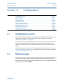
Section 2
Configuration
Configuration overview . . . . . . . . . . . . . . . . . . . . . . . . . . . . . . . . . . . . . . . . . . . . . . . . . . . . . .
Safety messages . . . . . . . . . . . . . . . . . . . . . . . . . . . . . . . . . . . . . . . . . . . . . . . . . . . . . . . . . . . .
System readiness . . . . . . . . . . . . . . . . . . . . . . . . . . . . . . . . . . . . . . . . . . . . . . . . . . . . . . . . . . .
Configuration basics . . . . . . . . . . . . . . . . . . . . . . . . . . . . . . . . . . . . . . . . . . . . . . . . . . . . . . . .
Verify configuration . . . . . . . . . . . . . . . . . . . . . . . . . . . . . . . . . . . . . . . . . . . . . . . . . . . . . . . . .
Basic setup of the transmitter . . . . . . . . . . . . . . . . . . . . . . . . . . . . . . . . . . . . . . . . . . . . . . . .
Configuring the LCD Display . . . . . . . . . . . . . . . . . . . . . . . . . . . . . . . . . . . . . . . . . . . . . . . . . .
Detailed transmitter setup . . . . . . . . . . . . . . . . . . . . . . . . . . . . . . . . . . . . . . . . . . . . . . . . . . .
Performing transmitter tests . . . . . . . . . . . . . . . . . . . . . . . . . . . . . . . . . . . . . . . . . . . . . . . . .
Configuring burst mode . . . . . . . . . . . . . . . . . . . . . . . . . . . . . . . . . . . . . . . . . . . . . . . . . . . . .
Establishing multidrop communication . . . . . . . . . . . . . . . . . . . . . . . . . . . . . . . . . . . . . . . .
2.1
page 7
page 7
page 8
page 9
page 12
page 14
page 20
page 21
page 27
page 29
page 30
Configuration overview
This section contains information on commissioning and tasks that should be performed on the
bench prior to installation, as well as tasks performed after installation as described in
“Performing transmitter tests” on page 27.
Field Communicator, AMS Device Manager, and Local Operator Interface (LOI) instructions are
given to perform configuration functions. For convenience, Field Communicator fast key
sequences are labeled “Fast Keys,” and abbreviated LOI menus are provided for each function
below.
Full Field Communicator menu trees and fast key sequences are available in Appendix C: Field
Communicator Menu Trees and Fast Keys . Local Operator Interface menu trees are available in
Appendix D: Local Operator Interface .
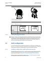
2.2
Safety messages
Procedures and instructions in this section may require special precautions to ensure the safety
of the personnel performing the operations. Information that raises potential safety issues is
indicated by a warning symbol (
). Refer to the following safety messages before performing
an operation preceded by this symbol.
Configuration
7
Reference Manual
Section 2: Configure
00809-0100-4107, Rev BA
June 2013
Explosions could result in death or serious injury:
Installation of this transmitter in an explosive environment must be in accordance with the
appropriate local, national, and international standards, codes, and practices. Please review
the approvals section of the Rosemount 2051 reference manual for any restrictions
associated with a safe installation.
Before connecting a Field Communicator in an explosive atmosphere, ensure the
instruments in the loop are installed in accordance with intrinsically safe or
non-incendive field wiring practices.
In an explosion-proof/flameproof installation, do not remove the transmitter covers
when power is applied to the unit.
Process leaks may cause harm or result in death.
Install and tighten process connectors before applying pressure.
Electrical shock can result in death or serious injury.
Avoid contact with the leads and terminals. High voltage that may be present on leads
can cause electrical shock.
2.3
2.3.1
System readiness
If using HART based control or asset management systems, confirm the HART
capability of such systems prior to commissioning and installation. Not all systems are
capable of communicating with HART revision 7 devices.
For instructions on how to change the HART revision of your transmitter, see
“Switching HART Revision” on page 80.
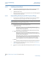
Confirm correct Device Driver
Verify the latest Device Driver (DD/DTM) is loaded on your systems to ensure proper communications.
1.
Download the latest DD at www.emersonprocess.com or www.hartcomm.org.
2. In the Browse by Member dropdown menu, select Rosemount business unit of Emerson
Process Management.
3. Select desired Product
a.
8
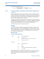
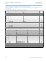
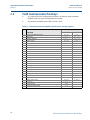
Within Table 2-1, use the HART Universal Revision and Device Revision numbers to find
the correct Device Driver
Configuration
Reference Manual
Section 2: Configure
00809-0100-4107, Rev BA
June 2013
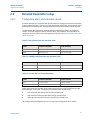
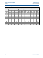
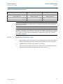
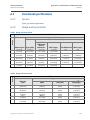
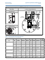
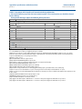
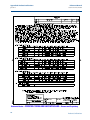
Table 2-1. Rosemount 2051 Device Revisions and files
Identify Device
NAMUR
Software
Software
Release Date Revision(1)
August 2012
January 1998
1.0.0
N/A
Find Device Driver
HART
HART
Software Universal
Device
Revision(2) Revision Revision(3)
01
178
7
10
5
9
5
3
Review
Instructions
Review
Functionality
Manual
Document
Number
Changes to
Software
00809-0100-4107
See footnote
(4)
for list of
changes.
00809-0100-4101
N/A
(1)
(1) NAMUR Software Revision is located on the hardware tag of the device.
(2) HART Software Revision can be read using a HART capable configuration tool.
(3) Device Driver file names use Device and DD Revision, e.g. 10_01. HART Protocol is designed to enable legacy device driver revisions to continue to
communicate with new HART devices. To access new functionality, the new Device Driver must be downloaded. It is recommended to download new
Device Driver files to ensure full functionality.
(4) HART Revision 5 and 7 Selectable, Safety Certified, Local Operator Interface, Scaled Variable, Configurable Alarms, Expanded Engineering Units.
2.4
Configuration basics
Set all transmitter hardware adjustments during commissioning to avoid exposing the
transmitter electronics to the plant environment after installation.
The Rosemount 2051 can be configured either before or after installation. Configuring the
transmitter on the bench using either a Field Communicator, AMS Device Manager, or Local
Operator Interface (LOI) ensures all transmitter components are in working order prior to
installation. Verify that the security switch is set in the unlock position ( ) in order to proceed
with configuration. See Figure 4-2 on page 59 for switch location.
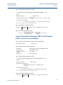
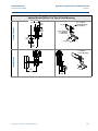
2.4.1
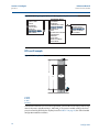
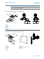
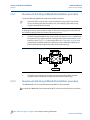
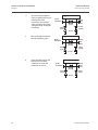
Configuring on the bench
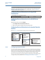
To configure on the bench, required equipment includes a power supply, and a Field
Communicator, AMS Device Manager, or an LOI (option M4). Wire equipment as shown in
Figure 2-1 below. To ensure successful HART communication, a resistance of at least 250 s
must be present between the transmitter and the power supply, see “Power supply for 4-20 mA
HART” on page 63 for details. Connect the Field Communicator leads to the terminals labeled
“COMM” on the terminal block or 1-5V configuration, wire as shown in Figure 2-1 on page 10.
The Field communicator is connected to the terminals labeled VOUT/COMM.
Configuration
9
Reference Manual
Section 2: Configure
00809-0100-4107, Rev BA
June 2013
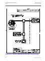
Figure 2-1. Wiring the Transmitter (4-20 mA HART)
A.
B.
A. Vdc supply
B. RL 250 (necessary for HART communication only)
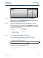
2.4.2
Configuration tools
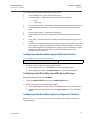
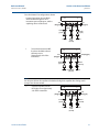
Figure 2-2. Wiring the Transmitter (1-5 Vdc Low Power)
A.
B.
A. DC power supply
B. Voltmeter
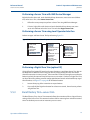
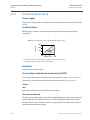
Configuring with a Field Communicator
There are two interfaces available with the Field Communicator: Traditional and Dashboard
interfaces. All steps using a Field Communicator will be described using Dashboard interfaces.
Figure 2-3 on page 11 shows the Device Dashboard interface. As stated in Section 2.3-System
readiness , it is critical that the latest DD’s are loaded into the Field Communicator. Visit
www.emersonprocess.com or www.hartcomm.org to download latest DD library.
Field Communicator menu trees and fast keys are available in Appendix C: Field Communicator
Menu Trees and Fast Keys .
10
Configuration
Reference Manual
Section 2: Configure
00809-0100-4107, Rev BA
June 2013
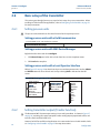
Figure 2-3. Device Dashboard
2051 FT 45B
Online
1. Overview
2. Configure
3. Service Tools
SAVE
Configuring with AMS Device Manager
Full configuration capability with AMS Device Manager requires loading the most current Device
Descriptor (DD) for this device. Download the latest DD at www.emersonprocess.com or
www.hartcomm.org.
Note
All steps using AMS Device Manager will be described using version 11.5.
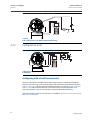
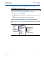
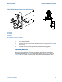
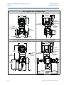
Configuring with a Local Operator Interface
The LOI requires option code M4 to be ordered. To activate the LOI push either configuration
button. Configuration buttons are located on the LCD Display (must remove housing cover to
access), or underneath the top tag of the transmitter. See Table 2-2 for configuration button
functionality and Figure 2-4 for configuration button location. When using the LOI for
configuration, several features require multiple screens for a successful configuration. Data
entered will be saved on a screen-by-screen basis; the LOI will indicate this by flashing "SAVED"
on the LCD Display each time.
Local Operator Interface menu trees are available in Appendix D: Local Operator Interface .
Configuration
11
Reference Manual
Section 2: Configure
00809-0100-4107, Rev BA
June 2013
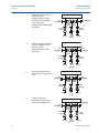
Figure 2-4. LOI configuration buttons
A
B
A. Internal configuration buttons
B. External configuration buttons
Table 2-2. LOI button operation
Button
Left
Right
2.4.3
No
Yes
SCROLL
ENTER
Setting the loop to manual
Whenever sending or requesting data that would disrupt the loop or change the output of the
transmitter, set the process application loop to manual control. The Field Communicator, AMS
Device Manager, or the LOI will prompt you to set the loop to manual when necessary. The
prompt is only a reminder; acknowledging this prompt does not set the loop to manual. It is
necessary to set the loop to manual control as a separate operation.
2.5
Verify configuration
It is recommended that various configuration parameters are verified prior to installation into
the process. The various parameters are detailed out for each configuration tool. Depending on
what configuration tool(s) are available follow the steps listed relevant to each tool.
2.5.1
Verifying configuration with Field Communicator
Configuration parameters listed in Table 2-3 are to be reviewed prior to transmitter installation.
A Full list of configuration parameters that can be reviewed and configured using a Field
Communicator are located in Appendix C: Field Communicator Menu Trees and Fast Keys .
Fast key sequences for the latest DD are shown in Table 2-3. For fast key sequences for legacy
DD's contact your local Emerson Process Representative.
12
Configuration
Reference Manual
Section 2: Configure
00809-0100-4107, Rev BA
June 2013
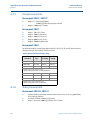
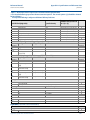
Table 2-3. Rosemount 2051 Device Dashboard fast key sequence
From the HOME screen, enter the fast key sequences listed
Fast Key Sequence
Function
Alarm and Saturation Levels
Damping
Primary Variable
Range Values
Tag
Transfer Function
Units
2.5.2
HART 7
HART 5
2, 2, 2, 5
2, 2, 1, 1, 5
2, 1, 1, 4, 1
2, 1, 1, 4
2, 2, 7, 1, 1
2, 2, 1, 1, 6
2, 2, 1, 1, 4
2, 2, 2, 5
2, 2, 1, 1, 5
2, 1, 1, 4, 1
2, 1, 1, 4
2, 2, 7, 1, 1
2, 2, 1, 1, 6
2, 2, 1, 1, 4
Verifying configuration with AMS Device Manager
Right click on the device and select Configuration Properties from the menu. Navigate the
tabs to review the transmitter configuration data.
2.5.3
Verifying configuration with Local Operator Interface
Press any configuration button to activate the LOI. Select VIEW CONFIG to review the below
parameters. Use the configuration buttons to navigate through the menu. The parameters to be
reviewed prior to installation include:
2.5.4
Tag
Primary Variable
Units
Range Values
Transfer Function
Damping
Alarm and Saturation
Levels
Verifying process variables configuration
This section describes how to verify that the correct process variables are selected.
Verifying process variables with a Field Communicator
From the HOME screen, enter the fast key sequence
Device Dashboard Fast Keys
3, 2, 1
Verifying process variables with AMS Device Manager
Right click on the device and select Overview from the menu.
1.
Configuration
Click the All Variables button to display the primary, secondary, tertiary and quaternary
variables.
13
Reference Manual
Section 2: Configure
00809-0100-4107, Rev BA
June 2013
2.6
Basic setup of the transmitter
This section goes through the necessary steps for basic setup of a pressure transmitter. When
installing in DP level or DP flow applications, refer to“Configuring Scaled Variable” on page 22
for setup instructions.
2.6.1
Setting pressure units
The pressure unit command sets the unit of measure for the reported pressure.
Setting pressure units with a Field Communicator
From the HOME screen, enter the fast key sequence
2, 2, 1, 1, 4
Device Dashboard Fast Keys
Setting pressure units with AMS Device Manager
Right click on the device and select Configure.
1.
Click Manual Setup and select desired units from Pressure Units dropdown menu.
2. Click Send when complete.
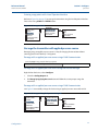
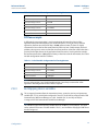
Setting pressure units with a Local Operator Interface
Follow Figure 2-5 on page 14 to select desired pressure and temperature units. Use the SCROLL
and ENTER buttons to select desired unit. Save by selecting SAVE as indicated on the LCD
screen.
Figure 2-5. Selecting Units with LOI
VIEW CONFIG
ZERO TRIM
UNITS
RERANGE
LOOP TEST
DISPLAY
EXTENDED MENU
EXIT MENU
2.6.2
UNITS
PRESS UNITS
TEMP UNITS
BACK TO MENU
EXIT MENU
PRESS UNITS
INH2O
MMHG
CMHG0C
MHG0C
PSI
PSF
ATM
TORR
PA
KPA
...
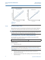
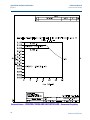
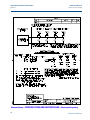
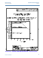
Setting transmitter output (Transfer Function)
The Rosemount 2051 has two output settings: Linear and Square Root. As shown in Figure 2-7
on page 16, activating the square root options makes analog output proportional to flow, and
includes a fixed Low Flow Cutoff at 5%.
14
However, for DP Flow and DP Level applications it is recommended to use Scaled Variable. Refer
to “Configuring Scaled Variable” on page 22 for setup instructions.
Configuration
Reference Manual
Section 2: Configure
00809-0100-4107, Rev BA
June 2013
Setting transmitter output with a Field Communicator
From the HOME screen, enter the fast key sequence
2, 2, 1, 1, 6
Device Dashboard Fast Keys
Setting transmitter output with AMS Device Manager
Right click on the device and select Configure.
1.
Click Manual Setup and choose output type from Analog Output Transfer Function and click
Send.
2. Carefully read the warning and click Yes if it is safe to apply the changes.
Setting transmitter output with a Local Operator Interface
Reference Figure 2-6 on page 15 to select either linear or square root transfer function using the
LOI.
Figure 2-6. Set output with LOI
VIEW CONFIG
ZERO TRIM
UNITS
RERANGE
LOOP TEST
DISPLAY
EXTENDED MENU
EXIT MENU
Configuration
EXTENDED MENU
CALIBRAT
DAMPING
TRANSFER FUNCT
SCALED VARIAB
ASSIGN PV
TAG
ALARM SAT
VALUES
PASSWORD
SIMLATE
HART REV
BACK TO MENU
EXIT MENU
TRANSFER FUNCT
LINEAR TRANSFER
FUNCTION
SQR ROOT TRANSFER
FUNCTION
BACK TO MENU
EXIT MENU
15
Reference Manual
Section 2: Configure
00809-0100-4107, Rev BA
June 2013
Figure 2-7. 4-20 mA HART square root output transition point
20mA
A
A
B
4mA
0
B
10
20
30
40
50
60
70
80
90
100
% Pressure Input
C
4mA
0
0.5
% Pressure Input
1
A. Square Root Curve
B. 5% Transition Point
C. 4% Transition Point
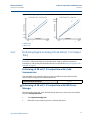
2.6.3
Rerange the transmitter
The Range Values command sets each of the lower and upper range analog values (4 and 20
mA/1-5 Vdc points) to a pressure. The lower range point represents 0% of range and the upper
range point represents 100% of range. In practice, the transmitter range values may be changed
as often as necessary to reflect changing process requirements. For a complete listing of Range
& Sensor limits, refer to “Range and sensor limits” on page 106.
Select from one of the methods below to rerange the transmitter. Each method is unique;
examine all options closely before deciding which method works best for your process.
Rerange by manually setting range points with a Field Communicator, AMS Device
Manager, or Local Operator Interface.
Rerange with a pressure input source and a Field Communicator, AMS Device Manager,
Local Operator Interface, or local zero and span buttons
Manually rerange the transmitter by entering range points
Entering range points with a Field Communicator
From the HOME screen, enter the fast key sequence
Device Dashboard Fast Keys
2, 2, 2, 1
Entering range points with AMS Device Manager
Right click on the device and select Configure:
1.
Click Manual Setup and select Analog Output.
2. Enter upper and lower range values in the Range Limits box and click Send.
16
3. Carefully read the warning and click Yes if it is safe to apply the changes.
Configuration
Reference Manual
Section 2: Configure
00809-0100-4107, Rev BA
June 2013
Entering range points with a Local Operator Interface
Reference Figure 2-8 on page 17 to rerange the transmitter using the Local Operator Interface.
Enter values using SCROLL and ENTER buttons.
Figure 2-8. Rerange with LOI
VIEW CONFIG
ZERO TRIM
UNITS
RERANGE
LOOP TEST
DISPLAY
EXTENDED MENU
EXIT MENU
RERANGE
ENTER VALUES
APPLY VALUES
BACK TO MENU
EXIT MENU
ENTER VALUES
LRV
URV
BACK TO MENU
EXIT MENU
Rerange the transmitter with applied pressure source
Reranging using an applied pressure source is a way of reranging the transmitter without
entering specific 4 and 20 mA (1-5 Vdc) points.
Rerange with an applied pressure source using a Field Communicator
From the HOME screen, enter the fast key sequence
2, 2, 2, 2
Device Dashboard Fast Keys
Rerange with an applied pressure source using AMS Device Manager
Right click on the device, select Configure.
1.
Select the Analog Output tab.
2. Click Range by Applying Pressure button and follow the screen prompts range the
transmitter.
Rerange with an applied pressure source using a Field Communicator
Use Figure 2-9 to manually rerange the device using an applied pressure source with an LOI.
Figure 2-9. Rerange with applied pressure using LOI
VIEW CONFIG
ZERO TRIM
UNITS
RERANGE
LOOP TEST
DISPLAY
EXTENDED MENU
EXIT MENU
Configuration
RERANGE
ENTER VALUES
APPLY VALUES
BACK TO MENU
EXIT MENU
APPLY VALUES
LRV
URV
BACK TO MENU
EXIT MENU
17
Reference Manual
Section 2: Configure
00809-0100-4107, Rev BA
June 2013
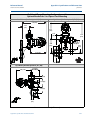
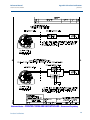
Rerange with an applied pressure source using local zero and span buttons
If ordered, local zero and span buttons (option code D4) can be used to rerange the transmitter
with an applied pressure. Refer to Figure 2-10 on page 18 for analog zero and span button
location.
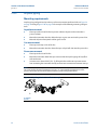
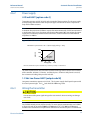
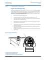
To rerange the transmitter using the span and zero buttons, perform the following procedure:
1.
Loosen the screw holding the top tag of the transmitter housing. Rotate the label to expose
the zero and span buttons.
2. Confirm device has local zero and span buttons by verifying blue retainer under the tag.
3. Apply transmitter pressure.
4. Rerange the transmitter.
a.
To change the zero (4mA/1V point) while maintaining the span: press and hold zero
button for at least two seconds then release.
b. To change the span (20mA/5V point) while maintaining the zero point: press and hold
the span button for at least two seconds and then release.
Note
4mA and 20mA points must maintain the minimum span defined in Appendix A: Functional
specifications .
Figure 2-10. Analog Zero and span buttons
A
A. Zero and span Buttons
If the transmitter security is on, adjustments to the zero and span will not be able to be
made. Refer to “Configuring transmitter security” on page 59 for security information.
18
The span is maintained when the 4mA/1V point is set. The span changes when the
20mA 5V point is set. If the lower range point is set to a value that causes the upper
range point to exceed the sensor limit, the upper range point is automatically set to the
sensor limit, and the span is adjusted accordingly.
Regardless of the range points, the Rosemount 2051 will measure and report all
readings within the digital limits of the sensor. For example, if the 4 and 20 mA(1-5 Vdc)
points are set to 0 and 10 inH2O, and the transmitter detects a pressure of 25 inH2O, it
digitally outputs the 25 inH2O reading and a 250% of range reading.
Configuration
Reference Manual
Section 2: Configure
00809-0100-4107, Rev BA
2.6.4
June 2013
Damping
The damping command changes the response time of the transmitter; higher values can
smooth variations in output readings caused by rapid input changes. Determine the appropriate
damping setting based on the necessary response time, signal stability, and other requirements
of the loop dynamics within your system. The damping command utilizes floating point
configuration allowing the user to input any damping value within 0.0-60.0 seconds.
Damping with a Field Communicator
From the HOME screen, enter the fast key sequence
2, 2, 1, 1, 5
Device Dashboard Fast Keys
Enter desired Damping Value and select APPLY.
Damping with AMS Device Manager
Right click on the device and select Configure.
1.
Select Manual Setup.
2. Within the Pressure Setup box, enter desired damping value and click Send.
3. Carefully read the warning and click Yes if it is safe to apply the changes.
Damping with a Local Operator Interface
Reference Figure 2-11 to enter damping values using an LOI.
Figure 2-11. Damping with LOI
VIEW CONFIG
ZERO TRIM
UNITS
RERANGE
LOOP TEST
DISPLAY
EXTENDED MENU
EXIT MENU
Configuration
EXTENDED MENU
CALIBRAT
DAMPING
TRANSFER FUNCT
SCALED VARIAB
ASSIGN PV
TAG
ALARM SAT VALUES
PASSWORD
SIMLATE
HART REV
BACK TO MENU
EXIT MENU
19
Reference Manual
Section 2: Configure
00809-0100-4107, Rev BA
June 2013
2.7
Configuring the LCD Display
The LCD Display configuration command allows customization of the LCD to suit application
requirements. The LCD will alternate between the selected items.
Pressure Units
Sensor Temperature
% of Range
mA/Vdc Output
Scaled Variable
In the following instructions, the LCD can also be configured to display configuration
information during the device startup. Select Review Parameters at Startup to enable or
disable this functionality.
Reference Figure 1-2 on page 4 LCD with Local Operator Interface for image of LCD screen.
Configuring LCD Display with a Field Communicator
From the HOME screen, enter the fast key sequence
2, 2, 4
Device Dashboard Fast Keys
Configuring LCD Display with AMS Device Manager
Right click on the device and select Configure.
1.
Click Manual Setup, select the Display tab.
2. Select desired display options and click Send.
Configuring LCD Display with a Local Operator Interface
Refer to Figure 2-12 for LCD Display configuration using a LOI.
Figure 2-12. Display with LOI
VIEW CONFIG
ZERO TRIM
UNITS
RERANGE
LOOP TEST
DISPLAY
EXTENDED MENU
EXIT MENU
20
DISPLAY
PRESS (on/off)
SCALED (on/off)
TEMP (on/off)
%RANGE (on/off)
ANALOG (on/off)
STRTUP (on/off)
BACK TO MENU
EXIT MENU
Configuration
Reference Manual
Section 2: Configure
00809-0100-4107, Rev BA
June 2013
2.8
Detailed transmitter setup
2.8.1
Configuring alarm and saturation levels
In normal operation, the transmitter will drive the output in response to pressure from the lower
to upper saturation points. If the pressure goes outside the sensor limits, or if the output would
be beyond the saturation points, the output will be limited to the associated saturation point.
The Rosemount 2051 transmitter automatically and continuously performs self-diagnostic
routines. If the self-diagnostic routines detect a failure, the transmitter drives the output to
configured alarm and value based on the position of the alarm switch. See “Setting Transmitter
alarm” on page 61.
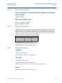
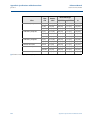
Table 2-4. Rosemount alarm and saturation values
Level
4–20 mA saturation
4–20 mA alarm
Low
3.9 mA (0.97 V)
3.75 mA (0.95 V)
High
20.8 mA (5.2 V)
21.75 mA (5.4 V)
Table 2-5. NAMUR-Compliant alarm and saturation values
Level
4–20 mA saturation
4–20 mA alarm
Low
3.8 mA (0.95 V)
3.6 mA (0.9 V)
High
20.5 mA (5.125 V)
22.5 mA (5.625 V)
Table 2-6. Custom Alarm and Saturation Values
Level
4–20 mA saturation
4–20 mA alarm
Low
3.7 mA - 3.9 mA
3.6 mA - 3.8 mA
High
20.1 mA - 22.9 mA
20.2 mA - 23.0 mA
Failure mode alarm and saturation levels can be configured using a Field Communicator, AMS
Device Manager, and the LOI. The following limitations exist for custom levels:
Low alarm level must be less than the low saturation level
High alarm level must be higher than the high saturation level
Alarm and saturation levels must be separated by at least 0.1 mA
The configuration tool will provide an error message if the configuration rule is violated.
Configuration
21
Reference Manual
Section 2: Configure
00809-0100-4107, Rev BA
June 2013
Note
Transmitters set to HART multidrop mode send all saturation and alarm information digitally;
saturation and alarm conditions will not affect the analog output. See also “Establishing
multidrop communication” on page 30.
Configuring Alarm and Saturation Levels using a Field
Communicator
From the HOME screen, enter the fast key sequence
2, 2, 2, 5
Device Dashboard Fast Keys
Configuring Alarm and Saturation Levels with AMS Device
Manager
Right click on the device, and select Configure.
1.
Click Configure Alarm and Saturation Levels button.
2. Follow screen prompts to configure Alarm and Saturation Levels.
Configuring Alarm and Saturation Levels using Local Operator
Interface
Refer to Figure 2-13 for instructions to configure alarm and saturation levels.
Figure 2-13. Configuring Alarm and Saturation with Local Operator Interface
VIEW CONFIG
ZERO TRIM
UNITS
RERANGE
LOOP TEST
DISPLAY
EXTENDED MENU
EXIT MENU
2.8.2
EXTENDED MENU
CALIBRAT
DAMPING
TRANSFER FUNCT
SCALED VARIAB
ASSIGN PV
TAG
ALARM SAT VALUES
PASSWORD
SIMULATE
HART REV
BACK TO MENU
EXIT MENU
ALARM SAT VALUES
ROSEMOUNT VALUES
NAMUR VALUES
OTHER VALUES
BACK TO MENU
EXIT MENU
Configuring Scaled Variable
The Scaled Variable configuration allows the user to create a relationship/conversion between
the pressure units and user-defined/custom units. There are two use cases for Scaled Variable.
The first use case is to allow custom units to be displayed on the transmitter's LCD/LOI Display.
The second use case is to allow custom units to drive the transmitter's 4-20 mA output.
If the user desires custom units to drive the 4-20 mA (1-5 Vdc) output, Scaled Variable must be
re-mapped as the primary variable. Refer to “Re-Mapping device variables” on page 25.
22
Configuration
Reference Manual
Section 2: Configure
00809-0100-4107, Rev BA
June 2013
The Scaled Variable configuration defines the following items:
Scaled Variable units - Custom units to be displayed.
Scaled data options - Defines the transfer function for the application
–
Linear
–
Square root
Pressure value position 1 - Lower known value point with consideration of linear offset.
Scaled Variable value position 1 - Custom unit equivalent to the lower known value
point.
Pressure value position 2 - Upper known value point
Scaled Variable value position 2 - Custom unit equivalent to the upper known value
point
Linear offset - The value required to zero out pressures effecting the desired pressure
reading.
Low flow cutoff - Point at which output is driven to zero to prevent problems caused by
process noise. It is highly recommended to use the low flow cutoff function in order to
have a stable output and avoid problems due to process noise at a low flow or no flow
condition. A low flow cutoff value that is practical for the flow element in the
application should be entered.
Configuring Scaled Variable using a Field Communicator
From the HOME screen, enter the fast key sequence
Device Dashboard Fast Keys
1.
2, 1, 4, 7
Follow the screen prompts to configure Scaled Variable.
a.
When configuring for level, select Linear under Select Scaled data options.
b. When configuring for flow, select Square Root under Select Scaled data options.
Configuring Scaled Variable using AMS Device Manager
Right click on the device and, select Configure.
1.
Select the Scaled Variable tab and click the Scaled Variable button.
2. Follow screen prompts to configure Scaled Variable
a.
When configuring for level applications, select Linear under Select Scaled data options.
b. When configuring for flow applications, select Square Root under Select Scaled data
options.
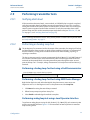
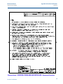
Configuring Scaled Variable using a Local Operator Interface
Refer to Figure 2-14 on page 24 for instructions to configure Scaled Variable using a Local
Operator Interface.
Configuration
23
Reference Manual
Section 2: Configure
00809-0100-4107, Rev BA
June 2013
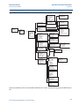
Figure 2-14. Configuring Scaled Variable using a Local Operator Interface
EXTENDED MENU
CALIBRAT
DAMPING
TRANSFER FUNCT
SCALED VARIAB
ASSIGN PV
TAG
ALARM SAT VALUES
PASSWORD
SIMLATE
HART REV
BACK TO MENU
EXIT MENU
VIEW CONFIG
ZERO TRIM
UNITS
RERANGE
LOOP TEST
DISPLAY
EXTENDED MENU
EXIT MENU
SCALED VARIAB
VIEW SCALED
CONFIG SCALED
BACK TO MENU
EXIT MENU
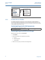
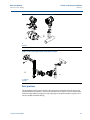
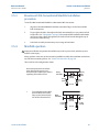
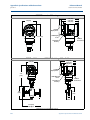
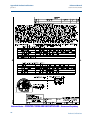
DP Level Example
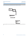
Figure 2-15. Example tank
A
D
B
H
L
C.
A. 230 in.
B. 200 in.
C. 12 in.
D. 0.94 sg
A differential transmitter is used in a level application. Once installed on an empty tank and taps
vented, the process variable reading is -209.4 inH2O. The process variable reading is the head
pressure created by fill fluid in the capillary. Based on Table 2-7 on page 25, the Scaled Variable
configuration would be as follows:
24
Configuration
Reference Manual
Section 2: Configure
00809-0100-4107, Rev BA
June 2013
Table 2-7. Scaled Variable Configuration for Tank Application
Scaled Variable units:
inch
Scaled data options:
linear
Pressure value position 1:
0 inH2O
Scaled Variable position 1:
12 in.
Pressure value position 2:
188 inH2O
Scaled Variable position 2:
212 in.
Linear offset:
-209.4 inH2O
DP Flow example
A differential pressure transmitter is used in conjunction with an orifice plate in a flow
application where the differential pressure at full scale flow is 125 inH2O. In this particular
application, the flow rate at full scale flow is 20,000 gallons of water per hour. It is highly
recommended to use the low flow cutoff function in order to have a stable output and avoid
problems due to process noise at a low flow or no flow condition. A low flow cutoff value that is
practical for the flow element in the application should be entered. In this particular example,
the low flow cutoff value is 1000 gallons of water per hour. Based on this information, the Scaled
Variable configuration would be as follows:
Table 2-8. Scaled Variable Configuration for Flow Application
Scaled Variable units:
gal/h
Scaled data options:
square root
Pressure value position 2:
125 inH2O
Scaled Variable position 2:
20,000 gal/h
Low Flow Cutoff:
1000 gal/h
Note
Pressure value position 1 and Scaled Variable position 1 are always set to zero for a flow
application. No configuration of these values is required.
2.8.3
Re-Mapping device variables
The re-mapping function allows the transmitter primary, secondary, tertiary, and quaternary
variables (PV, 2V, 3V, and 4V) to be configured as desired. The PV can be remapped with a Field
Communicator, AMS Device Manager, or a LOI. Variables (2V, 3V, and 4V) can only be
re-mapped via Field Communicator or AMS Device Manager.
Note
The variable assigned to the primary variable drives the 4-20mA (1-5 Vdc) output. This value
can be selected as Pressure or Scaled Variable. The 2, 3, and 4 variables only apply if HART burst
mode is being used.
Configuration
25
Reference Manual
Section 2: Configure
00809-0100-4107, Rev BA
June 2013
Re-mapping using a Field Communicator
From the HOME screen, enter the fast key sequence
2, 1, 1, 3
Fast Keys
Re-mapping using AMS Device Manager
Right click on the device and select Configure.
1.
Select Manual Setup and click on the HART tab.
2. Assign Primary, secondary, tertiary, and quaternary variables under Variable Mapping.
3. Click Send.
4. Carefully read the warning and click Yes if it is safe to apply the changes.
Re-mapping using Local Operator Interface
Refer to Figure 2-16 for instructions to remap the primary variable using a Local Operator
Interface.
Figure 2-16. Re-mapping with Local Operator Interface
VIEW CONFIG
ZERO TRIM
UNITS
RERANGE
LOOP TEST
DISPLAY
EXTENDED MENU
EXIT MENU
26
EXTENDED MENU
CALIBRAT
DAMPING
TRANSFER FUNCT
SCALED VARIAB
ASSIGN PV
TAG
ALARM SAT VALUES
PASSWORD
SIMULATE
HART REV
BACK TO MENU
EXIT MENU
Configuration
Reference Manual
Section 2: Configure
00809-0100-4107, Rev BA
June 2013
2.9
Performing transmitter tests
2.9.1
Verifying alarm level
If the transmitter electronics board, sensor module, or LCD/LOI Display is repaired or replaced,
verify the transmitter alarm level before returning the transmitter to service. This is useful in
testing the reaction of the control system to a transmitter in an alarm state. Thus ensuring the
control system recognizes the alarm when activated. To verify the transmitter alarm values,
perform a loop test and set the transmitter output to the alarm value (see Table 2-4, 2-5, and
2-6 on page 21, and “Verifying alarm level” on page 27).
Note
Before returning transmitter to service, verify security switch is set to the correct position. Refer
to “Verify configuration” on page 12.
2.9.2
Performing an Analog Loop Test
The Analog Loop Test command verifies the output of the transmitter, the integrity of the loop,
and the operations of any recorders or similar devices installed in the loop. It is recommended
that the 4-20 mA (1-5 Vdc) points in addition to alarm levels when installing, repairing, or
replacing a transmitter.
The host system may provide a current measurement for the 4-20 mA (1-5 Vdc) HART output. If
not, connect a reference meter to the transmitter by either connecting the meter to the test
terminals on the terminal block, or shunting transmitter power through the meter at some
point in the loop. For 1-5V output, voltage measurement is directly measured from Vout to (-)
terminals.
Performing a Analog Loop Test test using a Field Communicator
From the HOME screen, enter the fast key sequence
Device Dashboard Fast Keys
3, 5, 1
Performing a Analog Loop Test test using AMS Device Manager
Right click on the device and, within the Methods drop down menu, move cursor over
Diagnostics and Test. In the Diagnostics and Test drop down menu select Loop Test.
1.
Click Next after setting the control loop to manual.
2. Follow Screen prompts to perform a Loop Test.
3. Select Finish to acknowledge the method is complete.
Performing analog loop test using a Local Operator Interface
To perform an analog loop test using the LOI, the 4mA (1 V), 20mA (5V), and custom mA point
may be set manually. Reference Figure 2-17 for instructions on how to perform a transmitter
loop test using an LOI.
Configuration
27
Reference Manual
Section 2: Configure
00809-0100-4107, Rev BA
June 2013
Figure 2-17. Performing an analog loop test using an LOI
VIEW CONFIG
ZERO TRIM
UNITS
RERANGE
LOOP TEST
DISPLAY
EXTENDED MENU
EXIT MENU
2.9.3
LOOP TEST
SET 4MA(1V)
SET 20MA(5V)
SET CUSTOM
END LOOP TEST
BACK TO MENU
EXIT MENU
Simulate Device Variables
It is possible to temporarily set the Pressure, Sensor Temperature, or Scaled Variable to a
user-defined fixed value for testing purposes. Once the simulated variable method is left, the
process variable will be automatically returned to a live measurement. Simulate device variables
is only available in HART Revision 7 mode.
Simulate digital signal with a Field Communicator
From the HOME screen, enter the fast key sequence
Device Dashboard Fast Keys
3, 5
Simulate digital signal with AMS Device Manager
Right click on the device and select Service Tools.
1.
Click Simulate.
2. Under Device Variables select a digital value to simulate.
a.
Pressure
b. Sensor Temperature
c.
Scaled Variable
3. Follow the screen prompts to simulate selected digital value.
28
Configuration
Reference Manual
Section 2: Configure
00809-0100-4107, Rev BA
2.10
June 2013
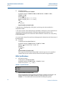
Configuring burst mode
Burst mode is compatible with the analog signal. Because the HART protocol features
simultaneous digital and analog data transmission, the analog value can drive other equipment
in the loop while the control system is receiving the digital information. Burst mode applies only
to the transmission of dynamic data (pressure and temperature in engineering units, pressure in
percent of range, Scaled Variable, and/or analog output), and does not affect the way other
transmitter data is accessed. However, when activated, bust mode can slow down
communication of non-dynamic data to the host by 50%.
Access to information other than dynamic transmitter data is obtained through the normal
poll/response method of HART communication. A Field Communicator, AMS Device Manager,
or the control system may request any of the information that is normally available while the
transmitter is in burst mode. Between each message sent by the transmitter, a short pause
allows the Field Communicator, AMS Device Manager, or a control system to initiate a request.
Choosing burst mode options in HART 5
Message content options:
PV only
Percent of Range
PV, 2V, 3V, 4V
Process Variables
Device Status
Choosing burst mode options in HART 7
Message content options:
PV only
Percent of Range
PV, 2V, 3V, 4V
Process Variables and Status
Process Variables
Device Status
Choosing a HART 7 Trigger Mode
When in HART 7 mode, the following trigger modes can be selected.
Configuration
Continuous (same as HART5 burst mode)
Rising
Falling
Windowed
On Change
29
Reference Manual
Section 2: Configure
00809-0100-4107, Rev BA
June 2013
Note
Consult your host system manufacturer for burst mode requirements.
Configuring burst mode using a Field Communicator
From the HOME screen, enter the fast key sequence
Device Dashboard Fast Keys
2, 2, 5, 3
Configuring burst mode using AMS Device Manager
Right click on the device and select Configure.
1.
Select the HART tab.
2. Enter the configuration in Burst Mode Configuration fields.
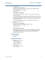
2.11
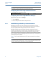
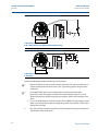
Establishing multidrop communication
Multidropping transmitters refers to the connection of several transmitters to a single
communications transmission line. Communication between the host and the transmitters
takes place digitally with the analog output of the transmitters deactivated.
Multidrop installation requires consideration of the update rate necessary from each
transmitter, the combination of transmitter models, and the length of the transmission line.
Communication with transmitters can be accomplished with HART modems and a host
implementing HART protocol. Each transmitter is identified by a unique address and responds
to the commands defined in the HART protocol. Field Communicators and AMS Device Manager
can test, configure, and format a multidropped transmitter the same way as a transmitter in a
standard point-to-point installation.
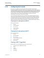
Figure 2-18 shows a typical multidrop network. This figure is not intended as an installation
diagram.
Note
A multidrop transmitter in HART Revision 7 mode has a fixed analog output of 4mA for all but
one device. Only one device is allowed to have an active analog signal.
30
Configuration
Reference Manual
Section 2: Configure
00809-0100-4107, Rev BA
June 2013
Figure 2-18. Typical multidrop network (4-20 mA only)
A.
B.
A. HART Modem
B. Power Supply
The Rosemount 2051 is set to address zero (0) at the factory, which allows operation in the
standard point-to-point manner with a 4–20 mA output signal. To activate multidrop
communication, the transmitter address must be changed to a number from 1 to 15 for HART
Revision 5, or 1-63 for HART Revision 7. This change deactivates the 4–20 mA analog output,
sending it to 4 mA. It also disables the failure mode alarm signal, which is controlled by the
upscale/downscale switch position. Failure signals in multidropped transmitters are
communicated through HART messages.
2.11.1
Changing a transmitter address
To activate multidrop communication, the transmitter poll address must be assigned a number
from 1 to 15 for HART Revision 5, and 1-63 for HART Revision 7. Each transmitter in a
multidropped loop must have a unique poll address.
Changing transmitter address using a Field Communicator
From the HOME screen, enter the fast key sequence
Device Dashboard Fast Keys
Configuration
HART Revision 5
HART Revision 7
2, 2, 5, 2, 1
2, 2, 5, 2, 2
31
Reference Manual
Section 2: Configure
00809-0100-4107, Rev BA
June 2013
Changing transmitter address using AMS Device Manager
Right click on the device and select Configure.
1.
In HART Revision 5 mode:
a.
Click on Manual Setup, select the HART tab.
b. In the Communication Settings box enter polling address in the Polling Address box,
click Send.
2. In HART Revision 7 mode:
a.
Click on Manual Setup, select the HART tab and click the Change Polling Address
button.
3. Carefully read the warning and click Yes if it is safe to apply the changes.
2.11.2
Communicating with a multidropped transmitter
To communicate with a multidrop transmitter, the Field Communicator or AMS Device Manager
has to be set up for Polling.
Communicating with a multidropped transmitter using a Field
Communicator
1.
Select Utility and Configure HART Application.
2. Select Polling Addresses.
3. Enter 0-63.
Communicating with a multidropped transmitter using AMS
Device Manager
Click on the HART modem icon and select Scan All Devices.
32
Configuration
Section 3: Hardware Installation
Reference Manual
June 2013
00809-0100-4107, Rev BA
Section 3
Hardware Installation
Overview . . . . . . . . . . . . . . . . . . . . . . . . . . . . . . . . . . . . . . . . . . . . . . . . . . . . . . . . . . . . . . . page 33
Safety messages . . . . . . . . . . . . . . . . . . . . . . . . . . . . . . . . . . . . . . . . . . . . . . . . . . . . . . . . . page 33
Considerations . . . . . . . . . . . . . . . . . . . . . . . . . . . . . . . . . . . . . . . . . . . . . . . . . . . . . . . . . . page 34
Installation procedures . . . . . . . . . . . . . . . . . . . . . . . . . . . . . . . . . . . . . . . . . . . . . . . . . . . page 35
Installation procedures . . . . . . . . . . . . . . . . . . . . . . . . . . . . . . . . . . . . . . . . . . . . . . . . . . . page 35
Rosemount 305, 306, and 304 Manifolds . . . . . . . . . . . . . . . . . . . . . . . . . . . . . . . . . . . page 47
3.1
Overview
The information in this section covers installation considerations for the Rosemount 2051 with
HART protocols. A Quick Installation Guide (document number 00825-0100-4107) is shipped
with every transmitter to describe recommended pipe-fitting and wiring procedures for initial
installation. Dimensional drawings for each Rosemount 2051 variation and mounting
configuration are included on page 38.
Note
For transmitter disassembly and reassembly refer to “Disassembly procedures” on page 89, and
“Reassembly procedures” on page 91.
3.2
Safety messages
Procedures and instructions in this section may require special precautions to ensure the safety
of the personnel performing the operation. Information that raises potential safety issues is
indicated by a warning symbol ( ). Refer to the following safety messages before performing
an operation preceded by this symbol.
Explosions could result in death or serious injury:
Installation of this transmitter in an explosive environment must be in accordance with the
appropriate local, national, and international standards, codes, and practices. Please review
the approvals section of the Rosemount 2051 reference manual for any restrictions
associated with a safe installation.
Before connecting a Field Communicator in an explosive atmosphere, ensure the
instruments in the loop are installed in accordance with intrinsically safe or
non-incendive field wiring practices.
In an Explosion-Proof/Flameproof installation, do not remove the transmitter covers
when power is applied to the unit.
Process leaks may cause harm or result in death.
Install and tighten process connectors before applying pressure.
Electrical shock can result in death or serious injury.
Hardware Installation
Avoid contact with the leads and terminals. High voltage that may be present on leads
can cause electrical shock.
33
Section 3: Hardware Installation
Reference Manual
00809-0100-4107, Rev BA
June 2013
Electrical shock can result in death or serious injury.
Avoid contact with the leads and terminals.
Process leaks could result in death or serious injury.
Install and tighten all four flange bolts before applying pressure.
Do not attempt to loosen or remove flange bolts while the transmitter is in service.
Replacement equipment or spare parts not approved by Emerson Process Management for
use as spare parts could reduce the pressure retaining capabilities of the transmitter and
may render the instrument dangerous.
Use only bolts supplied or sold by Emerson Process Management as spare parts.
Improper assembly of manifolds to traditional flange can damage sensor module.
For safe assembly of manifold to traditional flange, bolts must break back plane of
flange web (i.e., bolt hole) but must not contact sensor module housing.
3.3
Considerations
3.3.1
Installation considerations
Measurement accuracy depends upon proper installation of the transmitter and impulse piping.
Mount the transmitter close to the process and use a minimum of piping to achieve best
accuracy. Keep in mind the need for easy access, personnel safety, practical field calibration, and
a suitable transmitter environment. Install the transmitter to minimize vibration, shock, and
temperature fluctuation.
Important
Install the enclosed pipe plug (found in the box) in unused housing conduit opening with a
minimum of five threads of engagement to comply with explosion-proof requirements.
For material compatibility considerations, see document number 00816-0100-3045 on
www.emersonprocess.com/rosemount.
3.3.2
Environmental considerations
Best practice is to mount the transmitter in an environment that has minimal ambient
temperature change. The transmitter electronics temperature operating limits are –40 to 185 °F
(–40 to 85 °C). Refer to Appendix A: Specifications and Reference Data that lists the sensing
element operating limits. Mount the transmitter so that it is not susceptible to vibration and
mechanical shock and does not have external contact with corrosive materials.
34
Hardware Installation
Reference Manual
Section 3: Hardware Installation
00809-0100-4107, Rev BA
3.3.3
June 2013
Mechanical considerations
Steam service
For steam service or for applications with process temperatures greater than the limits of the
transmitter, do not blow down impulse piping through the transmitter. Flush lines with the
blocking valves closed and refill lines with water before resuming measurement. Refer to Figure
3-8 on page 42 through Figure 3-10 on page 43 for correct mounting orientation.
Side mounted
When the transmitter is mounted on its side, position the Coplanar flange to ensure proper
venting or draining. Mount the flange as shown in Figure 3-8 on page 42 through Figure 3-10 on
page 43, keeping drain/vent connections on the bottom for gas service and on the top for liquid
service.
3.4
Installation procedures
3.4.1
Mount the transmitter
For dimensional drawing information refer to Appendix A: Specifications and Reference Data on
page 115.
Process flange orientation
Mount the process flanges with sufficient clearance for process connections. For safety reasons,
place the drain/vent valves so the process fluid is directed away from possible human contact
when the vents are used. In addition, consider the need for a testing or calibration input.
Note
Most transmitters are calibrated in the horizontal position. Mounting the transmitter in any
other position will shift the zero point to the equivalent amount of liquid head pressure caused
by the varied mounting position. To reset zero point, refer to “Sensor Trim” on page 10.
Consider housing rotation
The electronics housing can be rotated up to 180 degrees in either direction to improve field
access, or to better view the optional LCD/LOI Display. To rotate the housing, perform the
following procedure:
1.
5
- -in. hex wrench.
Loosen the housing rotation set screw using a -----
2.
Turn the housing left or right up to 180° from its original position. Over rotating will
damage the transmitter.
3.
Retighten the housing rotation set screw.
Hardware Installation
64
35
Reference Manual
Section 3: Hardware Installation
00809-0100-4107, Rev BA
June 2013
Figure 3-1. Housing rotation
A
A. Housing Rotation Set Screw (5/64-in.)
Electronics housing clearance
Mount the transmitter so the terminal side is accessible. Clearance of 0.75 in. (19 mm) is
required for cover removal. Use a conduit plug in the unused conduit opening. Three inches of
clearance is required for cover removal if a meter is installed.
Environmental seal for housing
For NEMA 4X, IP66, and IP68 requirements, use thread seal (PTFE) tape or paste on male threads
of conduit to provide a watertight seal.
Always ensure a proper seal by installing the electronics housing cover(s) so that metal contacts
metal. Use Rosemount O-rings.
Flange bolts
The Rosemount 2051 can be shipped with a Coplanar flange or a Traditional flange installed
with four 1.75-inch flange bolts. Mounting bolts and bolting configurations for the Coplanar and
Traditional flanges can be found on page 37. Stainless steel bolts supplied by Emerson Process
Management are coated with a lubricant to ease installation. Carbon steel bolts do not require
lubrication. No additional lubricant should be applied when installing either type of bolt. Bolts
supplied by Emerson Process Management are identified by their head markings.
Bolt installation
Only use bolts supplied with the Rosemount 2051 or sold by Emerson Process Management as
spare parts for the Rosemount 2051 transmitter. The use of non approved bolts could reduce
pressure. Use the following bolt installation procedure:
Table 3-1. Bolt installation torque values
Bolt material
36
Initial torque value
Final torque value
CS-(ASTM-A445) Standard
300 in.-lb (34 N-m)
650 in.-lb (73 N-m)
Austemitic 316 SST—Option L4
150 in.-lb (17 N-m)
300 in.-lb (34 N-m)
ASTM A193 Grade B7M—Option L5
300 in.-lb (34 N-m)
650 in.-lb (73 N-m)
ASTM A 193 Class 2, Grade B8M
option L8
300 in.-lb (34 N-m)
650 in.-lb (73 N-m)
Hardware Installation
Reference Manual
Section 3: Hardware Installation
00809-0100-4107, Rev BA
June 2013
Figure 3-2. Traditional flange bolt configurations
A
B
C
D
C
C
E
E
F
A. Differential Transmitter
B. Gage/Absolute Transmitter
C. Drain/Vent
D. Plug
E. 1.75 (44) × 4
F. 1.50 (38) × 4(1)
Note: Dimensions are in inches (millimeters)
F
Figure 3-3. Mounting bolts and bolt configurations for coplanar flange
B.
A
Description
Qty
Size
in.
(mm)
Differential Pressure
Flange Bolts
4
1.75
(44)
Flange/Adapter Bolts
4
2.88
(73)
Flange Bolts
4
1.75
(44)
Flange/Adapter Bolts
2
2.88
(73)
Gage/Absolute Pressure (1)
C
D
(1) Rosemount 2051T transmitters are direct mount and do
not require bolts for process connection.
A. Transmitter with flange bolts
B.Transmitter with flange adapters and flange/adapter bolts
C. 1.75 (44) × 4
D. 2.88 (73) × 4
Hardware Installation
(1)
For Gage and Absolute Transmitters: 150 (38) x 2
37
Reference Manual
Section 3: Hardware Installation
00809-0100-4107, Rev BA
June 2013
Note:
Dimensions are in inches (millimeters).
Figure 3-4. Mounting bracket option codes B1, B7, and BA
B
A
C
D
E
F
A. 3.75 (95)
B. 1.63 (41)
C. 4.09 (104)
D. 2.73 (69)
E. 4.97 (126)
F. 2.81 (71)
Figure 3-5. Panel mounting bracket option codes B2 and B8
A
B
C
B
C
A
D
E
A. 3.75 (95)
B. 1.63 (41)
C. 4.09 (104)
D. 2.81 (71)
E. 4.5 (114)
38
D
A. 1.40 (36)
B. Mounting Holes 0.375 Diameter (10)
C. 1.405 (35,7)
D. 1.405 (35,7)
Hardware Installation
Reference Manual
Section 3: Hardware Installation
00809-0100-4107, Rev BA
June 2013
Figure 3-6. Flat mounting bracket option codes B3 and BC
B
A
D
C
A. 1.625 (41)
B. 2.125 (54)
C. 2.81 (71)
D. 8.00 (203)
Note: Dimensions are in inches (millimeters).
1.
Finger-tighten the bolts.
2.
Torque the bolts to the initial torque value using a crossing pattern (see Table 3.4.2 for
torque values).
3.
Torque the bolts to the final torque value using the same crossing pattern.
Mounting brackets
Rosemount 2051 transmitters may be panel-mounted or pipe-mounted via an optional
mounting bracket. Refer to Table 3-2 for the complete offering and see Figure 3-7 through
Figure 3-6 on pages 41 and 39 for dimensional and mounting configuration information.
Hardware Installation
39
Reference Manual
Section 3: Hardware Installation
00809-0100-4107, Rev BA
June 2013
Table 3-2. Mounting brackets
Rosemount 2051 brackets
Process connections
Option
code
B4
40
Mounting
Materials
Flat
Pipe
Panel panel
Coplanar In-line Traditional mount mount mount
X
X
X
B1
X
B2
X
B3
X
B7
X
B8
X
B9
X
BA
X
BC
X
X
CS
SST
bracket bracket
X
X
X
X
X
X
X
X
X
CS
bolts
X
SST
bolts
X
X
X
X
X
X
X
X
X
X
X
X
X
X
X
X
X
Hardware Installation
Reference Manual
Section 3: Hardware Installation
00809-0100-4107, Rev BA
June 2013
Figure 3-7. Mounting bracket option code B4
A.
D.
C.
B.
E
F
G
D
H
I
A. 5/16 x 11/2 Bolts for Panel Mounting(Not Supplied)
B. 3.4 (85)
C. 3/8-16 x 11/4 Bolts for Mounting to Transmitter
D. 2.8 (71)
Note: Dimensions are in inches (millimeters).
E. 3.85 (98)
F. 5.16 (131)
G. 1.99 (51)
H. 4.72 (120)
I. 6.90 (175)
B7M
Carbon Steel (CS) Head Markings
Stainless Steel (SST) Head Markings
Hardware Installation
660
CL A
316
B8M
KM
Alloy K-500 Head Marking
F593_*
*The last digit in the F593_ head marking may be
any letter between A and M.
41
Reference Manual
Section 3: Hardware Installation
00809-0100-4107, Rev BA
June 2013
3.4.2
Impulse piping
Mounting requirements
Impulse piping configurations depend on specific measurement conditions. Refer to Figure 3-8
on page 42 through Figure 3-10 on page 43 for examples of the following mounting configurations:
Liquid measurement
Place taps to the side of the line to prevent sediment deposits on the transmitter’s
process isolators.
Mount the transmitter beside or below the taps so gases can vent into the process line.
Mount drain/vent valve upward to allow gases to vent.
Gas measurement
Place taps in the top or side of the line.
Mount the transmitter beside or above the taps so liquid will drain into the process line.
Steam measurement
Place taps to the side of the line.
Mount the transmitter below the taps to ensure that the impulse piping will stay filled
with condensate.
In steam service above 250 °F (121 °C), fill impulse lines with water to prevent steam
from contacting the transmitter directly and to ensure accurate measurement start-up.
Note
For steam or other elevated temperature services, it is important that temperatures at the
process connection do not exceed the transmitter’s process temperature limits.
Figure 3-8. Liquid applications installation example
A
B
A. Coplanar
B. Inline
42
Hardware Installation
Reference Manual
Section 3: Hardware Installation
00809-0100-4107, Rev BA
June 2013
Figure 3-9. Gas applications installation example
A
B
A. Coplanar
B. Inline
Figure 3-10. Steam applications installation example
A
B
A. Coplanar
B. Inline
Best practices
The piping between the process and the transmitter must accurately transfer the pressure to
obtain accurate measurements. There are five possible sources of error: pressure transfer, leaks,
friction loss (particularly if purging is used), trapped gas in a liquid line, liquid in a gas line, and
density variations between the legs.
Hardware Installation
43
Section 3: Hardware Installation
Reference Manual
00809-0100-4107, Rev BA
June 2013
The best location for the transmitter in relation to the process pipe is dependent on the process.
Use the following guidelines to determine transmitter location and placement of impulse
piping:
3.4.3
Keep impulse piping as short as possible.
For liquid service, slope the impulse piping at least 1 in./foot (8 cm/m) upward from the
transmitter toward the process connection.
For gas service, slope the impulse piping at least 1 in./foot (8 cm/m) downward from
the transmitter toward the process connection.
Avoid high points in liquid lines and low points in gas lines.
Make sure both impulse legs are the same temperature.
Use impulse piping large enough to avoid friction effects and blockage.
Vent all gas from liquid piping legs.
When using a sealing fluid, fill both piping legs to the same level.
When purging, make the purge connection close to the process taps and purge
through equal lengths of the same size pipe. Avoid purging through the transmitter.
Keep corrosive or hot (above 250 °F [121 °C]) process material out of direct contact
with the sensor module and flanges.
Prevent sediment deposits in the impulse piping.
Maintain equal leg of head pressure on both legs of the impulse piping.
Avoid conditions that might allow process fluid to freeze within the process flange.
Process connections
Coplanar or traditional process connection
Install and tighten all four flange bolts before applying pressure, or process leakage will result.
When properly installed, the flange bolts will protrude through the top of the sensor module
housing. Do not attempt to loosen or remove the flange bolts while the transmitter is in service.
Flange adaptors:
Rosemount 2051DP and GP process connections on the transmitter flanges are 1/4–18 NPT.
Flange adapters are available with standard 1/2–14 NPT Class 2 connections. The flange adapters
allow users to disconnect from the process by removing the flange adapter bolts. Use
plant-approved lubricant or sealant when making the process connections. Refer to
Dimensional Drawings on page 113 for the distance between pressure connections. This
distance may be varied ±1/4 in. (6.4 mm) by rotating one or both of the flange adapters.
To install adapters to a Coplanar flange, perform the following procedure:
44
1.
Remove the flange bolts.
2.
Leaving the flange in place, move the adapters into position with the o-ring installed.
3.
Clamp the adapters and the Coplanar flange to the transmitter sensor module using the
larger of the bolts supplied.
4.
Tighten the bolts. Refer to “Flange bolts” on page 36 for torque specifications.
Hardware Installation
Reference Manual
Section 3: Hardware Installation
00809-0100-4107, Rev BA
June 2013
Whenever you remove flanges or adapters, visually inspect the PTFE o-rings. Replace with o-ring
designed for Rosemount transmitter if there are any signs of damage, such as nicks or cuts.
Undamaged o-rings may be reused. If you replace the o-rings, retorque the flange bolts after
installation to compensate for cold flow. Refer to the process sensor body reassembly procedure
in Section 5: Troubleshooting.
Note
PTFE O-rings should be replaced if the flange adapter is removed.
3.4.4
Inline process connection
Inline gage transmitter orientation
Interfering or blocking the atmospheric reference port will cause the transmitter to output
erroneous pressure values.
The low side pressure port on the inline gage transmitter is located in the neck of the
transmitter, behind the housing. The vent path is 360 degrees around the transmitter between
the housing and sensor (See Figure 3-11).
Keep the vent path free of any obstruction, such as paint, dust, and lubrication by mounting the
transmitter so that the process can drain away.
Figure 3-11. Inline gage low side pressure port
A
A. Low side pressure port (atmospheric reference)
Hardware Installation
45
Reference Manual
Section 3: Hardware Installation
00809-0100-4107, Rev BA
June 2013
Do not apply torque directly to the sensor module. Rotation between the sensor module
and the process connection can damage the electronics. To avoid damage, apply torque
only to the hex-shaped process connection.
Sensor Module
Process Connection
46
Hardware Installation
Reference Manual
Section 3: Hardware Installation
00809-0100-4107, Rev BA
3.5
June 2013
Rosemount 305, 306, and 304 Manifolds
The 305 Integral Manifold mounts directly to the transmitter and is available in two styles:
Traditional and Coplanar. The traditional 305 Integral Manifold can be mounted to most primary
elements with mounting adapters in the market today. The 306 Integral Manifold is used with
the Rosemount 2051T in-line transmitters to provide block-and-bleed valve capabilities of up to
10000 psi (690 bar).
Figure 3-12. Manifolds
ROSEMOUNT 2051C
AND 304
CONVENTIONAL
ROSEMOUNT 2051C AND 305
INTEGRAL TRADITIONAL
ROSEMOUNT 2051C AND
305 INTEGRAL
COPLANAR
ROSEMOUNT 2051T
AND 306 IN-LINE
The 304 conventional manifold combines a traditional flange and manifold that can be mounted
to most primary elements.
Hardware Installation
47
Section 3: Hardware Installation
3.5.1
Reference Manual
00809-0100-4107, Rev BA
June 2013
Rosemount 305 Integral Manifold installation procedure
To install a 305 Integral Manifold to a Rosemount 2051 transmitter:
1.
Inspect the PTFE sensor module o-rings. Undamaged o-rings may be reused. If the
o-rings are damaged (if they have nicks or cuts, for example), replace with o-rings
designed for Rosemount transmitter.
Important
If replacing the o-rings, take care not to scratch or deface the o-ring grooves or the surface of
the isolating diaphragm while you remove the damaged o-rings.
2.
Install the Integral Manifold on the sensor module. Use the four 2.25-in. manifold bolts
for alignment. Finger tighten the bolts, then tighten the bolts incrementally in a cross
pattern as seen in Figure 3-13 to final torque value. See “Flange bolts” on page 36 for
complete bolt installation information and torque values. When fully tightened, the
bolts should extend through the top of the sensor module housing.
Figure 3-13. Bolt tightening pattern
3.
3.5.2
If the PTFE sensor module o-rings have been replaced, the flange bolts should be
re-tightened after installation to compensate for cold flow of the o-rings.
Rosemount 306 Integral Manifold installation procedure
The 306 Manifold is for use only with a Rosemount 2051T In-line transmitter.
Assemble the 306 Manifold to the Rosemount 2051T In-line transmitter with a thread sealant.
See “Safety messages” on page 33 for complete warning information.
48
Hardware Installation
Reference Manual
Section 3: Hardware Installation
00809-0100-4107, Rev BA
3.5.3
June 2013
Rosemount 304 Conventional Manifold installation
procedure
To install a 304 Conventional Manifold to a Rosemount 2051 transmitter:
3.5.4
1.
Align the Conventional Manifold with the transmitter flange. Use the four manifold
bolts for alignment.
2.
Finger tighten the bolts, then tighten the bolts incrementally in a cross pattern to final
torque value. See “Flange bolts” on page 36 for complete bolt installation information
and torque values. When fully tightened, the bolts should extend through the top of
the sensor module housing.
3.
Leak-check assembly to maximum pressure range of transmitter.
Manifold operation
Improper installation or operation of manifolds may result in process leaks, which may cause
death or serious injury.
Always perform a zero trim on the transmitter/manifold assembly after installation to eliminate
any shift due to mounting effects. See “Sensor Trim Overview” on page 10.
Three and five-valve configurations shown:
In normal operation the two block
valves between the process and
instrument ports will be open and the
equalizing valve will be closed.
L
H
Drain/
Vent Valve
Drain/
Vent
Valve
Equalize
(closed)
Isolate
(open)
Isolate
(open)
Process
1.
To zero the Rosemount 2051,
close the block valve to the
low pressure (downstream)
side of the transmitter first.
L
H
Drain/
Vent Valve
Equalize
(closed)
Isolate
(open)
Drain/
Vent
Valve
Isolate
(closed)
Process
Hardware Installation
49
Reference Manual
Section 3: Hardware Installation
00809-0100-4107, Rev BA
June 2013
2.
Open the center (equalize)
valve to equalize the pressure
on both sides of the
transmitter. The manifold
valves are now in the proper
configuration for zeroing the
transmitter.
L
H
Drain/
Vent Valve
Drain/
Vent
Valve
Equalize
(open)
Isolate
(closed)
Isolate
(open)
Process
3.
After zeroing the transmitter,
close the equalizing valve.
L
H
Drain/
Vent Valve
Drain/
Vent
Valve
Equalize
(closed)
Isolate
(closed)
Isolate
(open)
Process
4.
Open the block valve on the
low pressure side of the
transmitter to return the
transmitter to service.
L
H
Drain/
Vent Valve
Equalize
(closed)
Isolate
(open)
Drain/
Vent
Valve
Isolate
(open)
Process
50
Hardware Installation
Reference Manual
Section 3: Hardware Installation
00809-0100-4107, Rev BA
June 2013
Five-valve Natural Gas configurations shown:
In normal operation, the two block
valves between the process and
instrument ports will be open, and the
equalizing valves will be closed.
L
H
Test
(Plugged)
Test
(Plugged)
Equalize
(closed)
Equalize
(closed)
Isolate
(open)
Isolate
(open)
Process
1.
To zero the Rosemount 2051,
first close the block valve on
the low pressure
(downstream) side of the
transmitter.
Drain
Vent
(closed)
Process
L
H
Test (Plugged)
Test
(Plugged)
Equalize
(closed)
Equalize
(closed)
Isolate
(open)
Isolate
(closed)
Process
Drain Vent
(closed)
Process
Note
Do not open the low side equalize valve before the high side equalize valve. Doing so will
overpressure the transmitter.
2.
Open the equalize valve on
the high pressure (upstream)
side of the transmitter.
L
H
Test
(Plugged)
Test
(Plugged)
Equalize
(open)
Equalize
(closed)
Isolate
(open)
Process
Hardware Installation
Isolate
(closed)
Drain
Vent
(closed)
Process
51
Reference Manual
Section 3: Hardware Installation
00809-0100-4107, Rev BA
June 2013
3.
Open the equalize valve on
the low pressure
(downstream) side of the
transmitter. The manifold is
now in the proper
configuration for zeroing the
transmitter.
L
H
Test (Plugged)
Test
(Plugged)
Equalize
(open)
Isolate
(open)
Isolate
(closed)
Process
4.
After zeroing the transmitter,
close the equalize valve on
the low pressure
(downstream) side of the
transmitter.
Equalize
(open)
Drain
Vent
(closed)
Process
L
H
Test
(Plugged)
Test
(Plugged)
Equalize
(open)
Equalize
(closed)
Isolate
(open)
Isolate
(closed)
Process
5.
Close the equalize valve on
the high pressure (upstream)
side.
Drain
Vent
(closed)
Process
L
H
Test
(Plugged)
Test
(Plugged)
Equalize
(closed)
Equalize
(closed)
Isolate
(open)
Isolate
(closed)
Process
6.
Finally, to return the
transmitter to service, open
the low side isolation valve.
Drain
Vent
(closed)
Process
L
H
Test (Plugged)
Test
(Plugged)
Equalize
(closed)
Equalize
(closed)
Isolate
(open)
Process
52
Isolate
(open)
Drain
Vent
(closed)
Process
Hardware Installation
Section 4: Electrical Installation
Reference Manual
June 2013
00809-0100-4107, Rev BA
Section 4
Electrical Installation
Overview . . . . . . . . . . . . . . . . . . . . . . . . . . . . . . . . . . . . . . . . . . . . . . . . . . . . . . . . . . . . . . . page 53
Safety messages . . . . . . . . . . . . . . . . . . . . . . . . . . . . . . . . . . . . . . . . . . . . . . . . . . . . . . . . . page 53
LCD/LOI Display . . . . . . . . . . . . . . . . . . . . . . . . . . . . . . . . . . . . . . . . . . . . . . . . . . . . . . . . . . page 54
Configuring transmitter security . . . . . . . . . . . . . . . . . . . . . . . . . . . . . . . . . . . . . . . . . . . . page 55
Setting Transmitter alarm . . . . . . . . . . . . . . . . . . . . . . . . . . . . . . . . . . . . . . . . . . . . . . . . . . page 57
Electrical considerations . . . . . . . . . . . . . . . . . . . . . . . . . . . . . . . . . . . . . . . . . . . . . . . . . . page 58
Transient protection terminal block grounding . . . . . . . . . . . . . . . . . . . . . . . . . . . . . page 63
4.1
Overview
The information in this section covers installation considerations for the Rosemount 2051. A
Quick Installation Guide is shipped with every transmitter to describe pipe-fitting, wiring
procedures, and basic configuration for initial installation.
Note
For transmitter disassembly and reassembly refer to sections “Disassembly procedures” on
page 89, and “Reassembly procedures” on page 91.
4.2
Safety messages
Procedures and instructions in this section may require special precautions to ensure the safety
of the personnel performing the operations. Information that raises potential safety issues is
indicated by a warning symbol (
). Refer to the following safety messages before performing
an operation preceded by this symbol.
Explosions could result in death or serious injury:
Installation of this transmitter in an explosive environment must be in accordance with the
appropriate local, national, and international standards, codes, and practices. Please review
the approvals section of the Rosemount 2051 reference manual for any restrictions
associated with a safe installation.
In an Explosion-Proof/Flameproof installation, do not remove the transmitter covers
when power is applied to the unit.
Process leaks may cause harm or result in death.
Install and tighten process connectors before applying pressure.
Electrical shock can result in death or serious injury.
Electrical Installation
Avoid contact with the leads and terminals. High voltage that may be present on leads
can cause electrical shock.
53
Reference Manual
Section 4: Electrical Installation
00809-0100-4107, Rev BA
June 2013
4.3
LCD/LOI Display
Transmitters ordered with the LCD option (M5) or LOI option (M4) are shipped with the display
installed. Installing the display on an existing Rosemount 2051 transmitter requires a small
instrument screwdriver. Carefully align the desired display connector with the electronics board
connector. If connectors don't align, the display and electronics board are not compatible.
Figure 4-1. LOI Display assembly
A
B
A. LCD/LOI Display
B. Extended cover
4.3.1
Rotating LCD/LOI Display
1.
Secure the loop to manual control and remove power to transmitter.
2.
Remove transmitter housing cover.
3.
Remove screws form the LCD/LOI Display and rotate to desired orientation.
a.
54
Insert 10 pin connector into the display board for the correct orientation. Carefully
align pins for insertion into the output board.
4.
Re-insert screws.
5.
Reattach transmitter housing cover; cover must be fully engaged to comply with
explosion proof requirements.
6.
Re-attach power and return loop to automatic control.
Electrical Installation
Reference Manual
Section 4: Electrical Installation
00809-0100-4107, Rev BA
4.4
June 2013
Configuring transmitter security
There are four security methods with the Rosemount 2051 transmitter.
Security switch
HART Lock
Configuration Buttons lock
LOI password
Figure 4-2. 4-20 mA electronics board
Without LCD Meter
With LCD/LOI Display
A
B
A. Alarm
B. Security
Note
1-5 Vdc Alarm and Security switches are located in the same location as 4-20 mA output boards.
4.4.1
Setting security switch
The security switch is used to prevent changes to the transmitter configuration data. If the
security switch is set to the locked location ( ), any transmitter configuration requests sent via
HART, LOI, or local configuration buttons will be rejected by the transmitter and the transmitter
configuration data will not be modified. Reference Figure 4-2 for the location of the security
switch. Follow the steps below to enable the security switch.
1.
Set loop to manual and remove power.
2.
Remove transmitter housing cover.
3.
Use a small screwdriver to slide the switch to the lock (
4.
Replace transmitter housing cover; cover must be fully engaged to comply with
explosion proof requirements.
Electrical Installation
) position.
55
Reference Manual
Section 4: Electrical Installation
00809-0100-4107, Rev BA
June 2013
4.4.2
HART Lock
The HART Lock prevents changes to the transmitter configuration from all sources; all changes
requested via HART, LOI, and local configuration buttons will be rejected. The HART Lock can
only be set via HART communication, and is only available in HART Revision 7 mode. The HART
Lock can be enabled or disabled with a Field Communicator or AMS Device Manager.
Configuring HART Lock using Field Communicator
From the HOME screen, enter the fast key sequence
Device Dashboard Fast Keys
2, 2, 6, 4
Configuring HART Lock using AMS device Manager
4.4.3
1.
Right click on the device and select Configure.
2.
Under Manual Setup select the Security tab.
3.
Click Lock/Unlock button under HART Lock (Software) and follow the screen prompts.
Configuration Button lock
The configuration button lock disables all local button functionality. Changes to the transmitter
configuration from the LOI and local buttons will be rejected. Local external keys can be locked
via HART communication only.
Configuring configuration button lock using a Field
Communicator
From the HOME screen, enter the fast key sequence
Device Dashboard Fast Keys
2, 2, 6, 3
Configuring configuration button lock using AMS device Manager
56
1.
Right click on the device and select Configure.
2.
Under Manual Setup select the Security tab.
3.
Within the Configuration Buttons dropdown menu select Disabled to lock external local
keys.
4.
Click Send.
5.
Confirm service reason and click Yes.
Electrical Installation
Reference Manual
Section 4: Electrical Installation
00809-0100-4107, Rev BA
4.4.4
June 2013
Local Operator Interface Password
A Local Operator Interface Password can be entered and enabled to prevent review and
modification of device configuration via the LOI. This does not prevent configuration from HART
or external keys (analog zero and span; Digital Zero Trim). The LOI password is a 4 digit code
that is to be set by the user. If the password is lost or forgotten the master password is “9307”.
The LOI password can be configured and enabled/disabled by HART communication via a Field
Communicator, AMS Device Manager, or the LOI.
Configuring LOI password with Field Communicator
From the HOME screen, enter the fast key sequence
2, 2, 6, 5, 2
Device Dashboard Fast Keys
Configuring LOI password with AMS Device Manager
1.
Right click on the device and select Configure.
2.
Under Manual Setup select the Security tab.
3.
Within the Local Operator Interface click the Configure Password button and follow the
screen prompts.
Configuring LOI password using Local Operator Interface
Figure 4-3. Local Operator Interface password
VIEW CONFIG
ZERO TRIM
UNITS
RERANGE
LOOP TEST
DISPLAY
EXTENDED MENU
EXIT MENU
4.5
EXTENDED MENU
CALIBRAT
DAMPING
TRANSFER FUNCT
SCALED VARIAB
ASSIGN P
TAG
ALARM SAT VALUES
PASSWORD
SIMULATE
HART REV
BACK TO MENU
EXIT MENU
PASSWORD
PASSWORD ENABLE
CHANGE PASSWORD
BACK TO MENU
EXIT MENU
Setting Transmitter alarm
On the electronics board is an alarm switch, reference Figure 4-2 on page 55 for switch location.
Follow the steps below to change the alarm switch location.
1.
Set loop to manual and remove power.
2.
Remove transmitter housing cover.
3.
Use a small screwdriver to slide switch to desired position.
4.
Replace transmitter cover; cover must be fully engaged to comply with explosion proof
requirements.
Electrical Installation
57
Reference Manual
Section 4: Electrical Installation
00809-0100-4107, Rev BA
June 2013
4.6
Electrical considerations
Note
Make sure all electrical installation is in accordance with national and local code requirements.
Do not run signal wiring in conduit or open trays with power wiring or near heavy electrical
equipment.
4.6.1
Conduit installation
If all connections are not sealed, excess moisture accumulation can damage the
transmitter. Make sure to mount the transmitter with the electrical housing positioned
downward for drainage. To avoid moisture accumulation in the housing, install wiring with
a drip loop, and ensure the bottom of the drip loop is mounted lower than the conduit
connections of the transmitter housing.
Recommended conduit connections are shown in Figure 4-4.
Figure 4-4. Conduit installation diagrams.
A.
B.
B.
A.
A. Possible conduit line positions
B. Sealing compound
58
Electrical Installation
Reference Manual
Section 4: Electrical Installation
00809-0100-4107, Rev BA
4.6.2
June 2013
Power supply
4-20 mA HART (option code A)
Transmitter operates on 10.5-42.4 Vdc at the terminal of the transmitter. The dc power supply
should provide power with less than two percent ripple. A minimum of 16.6V is required for
loops with a 250 resistance.
Note
A minimum loop resistance of 250 s is required to communicate with a Field Communicator. If
a single power supply is used to power more than one Rosemount 2051 transmitter, the power
supply used, and circuitry common to the transmitters, should not have more that 20 s of
impedance at 1200 Hz.
Figure 4-5. Load limitation
Maximum Loop Resistance = 43.5 * (Power Supply Voltage – 10.5)
Load (s)
1387
1000
500
Operating
Region
0
10.5
20
30
Voltage (Vdc)
42.4
The Field Communicator requires a minimum loop resistance of 250 for communication.
The total resistance load is the sum of the resistance of the signal leads and the load resistance
of the controller, indicator, I.S. Barriers, and related pieces. If intrinsic safety barriers are used,
the resistance and voltage drop must be included.
1-5 Vdc Low Power HART (output code M)
Low power transmitters operate on 9-28 Vdc. The dc power supply should provide power with
less than 2 percent ripple. The Vout load should be 100 k or greater.
4.6.3
Wiring the transmitter
Do not connect the power signal wiring to the test terminals. Incorrect wiring can damage
test circuit.
Note
Use shielded twisted pairs to yield best results. To ensure proper communication, use 24 AWG
or larger wire and do not exceed 5000 feet (1500 meters). For 1-5V 500 feet (150meters)
maximum are recommended. unpaired three conductor or two twisted pairs is recommended.
Electrical Installation
59
Reference Manual
Section 4: Electrical Installation
00809-0100-4107, Rev BA
June 2013
Figure 4-6. Wiring the transmitter (4-20 mA HART)
A.
B.
A. DC power supply
B. RL 250 (necessary for HART communication only)
Figure 4-7. Wiring the Transmitter (1-5 Vdc Low Power)
A.
B.
A. DC power supply
B. Voltmeter
Perform the following procedure to make wiring connections:
1.
Remove the housing cover on terminal compartment side. Do not remove the cover in
explosive atmospheres when the circuit is live. Signal wiring supplies all power to the
transmitter.
2.
For 4-20 mA HART output, connect the positive lead to the terminal marked
(pwr/comm+) and the negative lead to the terminal marked (pwr/comm -). Do not
connect the powered signal wiring to the test terminals. Power could damage the test
diode.
a.
3.
60
For 1-5 Vdc HART Output, connect the positive lead to (PWR +) and the negative to the
(PWR -). Do not connect the powered signal wiring to the test terminals. Power could
damage the test diode.
Plug and seal unused conduit connection on the transmitter housing to avoid moisture
accumulation in the terminal side.
Electrical Installation
Reference Manual
Section 4: Electrical Installation
00809-0100-4107, Rev BA
4.6.4
June 2013
Grounding the transmitter
Signal cable shield grounding
Signal cable shield grounding is summarized in Figure 4-8 on page 61. The signal cable shield
and unused shield drain wire must be trimmed and insulated, ensuring that the signal cable
shield and drain wire do not come in contact with the transmitter case. See “Transmitter case
grounding” on page 62 for instructions on grounding the transmitter case. Follow the steps
below to correctly ground the signal cable shield.
1.
Remove the Field Terminals Housing Cover.
2.
Connect the signal wire pair at the field terminals as indicated in Figure 4-6.
3.
At the field terminals, the cable shield and shield drain wire should be trimmed close
and insulated from transmitter housing.
4.
Reattach the Field Terminals Housing Cover; cover must be fully engaged to comply
with explosion proof requirements.
5.
At terminations outside the transmitter housing, the cable shield drain wire should be
continuously connected.
a.
6.
Prior to the termination point, any exposed shield drain wire should be insulated as
shown in Figure 4-8 (B).
Properly terminate the signal cable shield drain wire to an earth ground at or near the
power supply.
Figure 4-8. Wiring pair and ground
A.
DP
C.
B.
A. Insulate shield and shield drain wire
B. Insulate exposed shield drain wire
C. Terminate cable shield drain wire to earth ground
Electrical Installation
61
Reference Manual
Section 4: Electrical Installation
00809-0100-4107, Rev BA
June 2013
Transmitter case grounding
Always ground the transmitter case in accordance with national and local electrical codes. The
most effective transmitter case grounding method is a direct connection to earth ground with
minimal impedance. Methods for grounding the transmitter case include:
Internal Ground Connection: The Internal Ground Connection screw is inside the FIELD
TERMINALS side of the electronics housing. This screw is identified by a ground symbol
( ). The ground connection screw is standard on all Rosemount 2051 transmitters.
Refer to Figure 4-9 on page 62.
External ground connection: The external ground connection is located on the exterior
of the transmitter housing. Refer to Figure 4-10 on page 62. This connection is only
available with option V5 and T1.
Figure 4-9. Internal ground connection
A.
A. Internal ground location
Figure 4-10. External ground connection (option V5 or T1)
A.
A. External ground location
Note
Grounding the transmitter case via threaded conduit connection may not provide sufficient
ground continuity.
62
Electrical Installation
Reference Manual
Section 4: Electrical Installation
00809-0100-4107, Rev BA
June 2013
Transient protection terminal block grounding
The transmitter can withstand electrical transients of the energy level usually encountered in
static discharges or induced switching transients. However, high-energy transients, such as
those induced in wiring from nearby lightning strikes, can damage the transmitter.
The transient protection terminal block can be ordered as an installed option (Option Code T1)
or as a spare part to retrofit existing Rosemount 2051 transmitters in the field. See “Spare parts”
on page 171 for part numbers. The lightning bolt symbol shown in Figure 4-11 on page 63
identifies the transient protection terminal block.
Figure 4-11. Transient protection Terminal Block
A
A. Lightning bolt location
Note
The transient protection terminal block does not provide transient protection unless the
transmitter case is properly grounded. Use the guidelines to ground the transmitter case. Refer
to Figure 4-11.
Electrical Installation
63
Section 4: Electrical Installation
June 2013
64
Reference Manual
00809-0100-4107, Rev BA
Electrical Installation
Section 5: Operation and Maintenance
Reference Manual
June 2013
00809-0100-4107, Rev BA
Section 5
Operation and Maintenance
Overview . . . . . . . . . . . . . . . . . . . . . . . . . . . . . . . . . . . . . . . . . . . . . . . . . . . . . . . . . . . . . . . page 65
Safety messages . . . . . . . . . . . . . . . . . . . . . . . . . . . . . . . . . . . . . . . . . . . . . . . . . . . . . . . . . page 65
Calibration overview . . . . . . . . . . . . . . . . . . . . . . . . . . . . . . . . . . . . . . . . . . . . . . . . . . . . . page 66
Trim the pressure signal . . . . . . . . . . . . . . . . . . . . . . . . . . . . . . . . . . . . . . . . . . . . . . . . . . page 71
Perform a Sensor Trim . . . . . . . . . . . . . . . . . . . . . . . . . . . . . . . . . . . . . . . . . . . . . . . . . . . . page 72
Switching HART Revision . . . . . . . . . . . . . . . . . . . . . . . . . . . . . . . . . . . . . . . . . . . . . . . . . page 78
5.1
Overview
This section contains information on calibrating Rosemount 2051 Pressure Transmitters.
Field Communicator, AMS, Device Manager and Local Operator Interface (LOI) instructions are
given to perform configuration functions.
5.2
Safety messages
Procedures and instructions in this section may require special precautions to ensure the safety
of the personnel performing the operations. Information that raises potential safety issues is
indicated by a warning symbol (
). Refer to the following safety messages before performing
an operation preceded by this symbol.
5.2.1
Warnings
Explosions could result in death or serious injury:
Installation of this transmitter in an explosive environment must be in accordance with the
appropriate local, national, and international standards, codes, and practices. Please review
the approvals section of the Rosemount 2051 reference manual for any restrictions
associated with a safe installation.
Before connecting a Field Communicator in an explosive atmosphere, ensure the
instruments in the loop are installed in accordance with intrinsically safe or
non-incendive field wiring practices.
In an Explosion-Proof/Flameproof installation, do not remove the transmitter covers
when power is applied to the unit.
Process leaks may cause harm or result in death.
Install and tighten process connectors before applying pressure.
Electrical shock can result in death or serious injury.
Avoid contact with the leads and terminals. High voltage that may be present on leads
can cause electrical shock.
Operation and Maintenance
65
Reference Manual
Section 5: Operation and Maintenance
00809-0100-4107, Rev BA
June 2013
5.3
Recommended calibration tasks
Absolute pressure transmitters (Rosemount 2051CA and Rosemount 2051TA) are
calibrated at the factory. Trimming adjusts the position of the factory characterization
curve. It is possible to degrade performance of the transmitter if any trim is done
improperly or with inaccurate equipment.
Table 5-1. Basic and full calibration tasks
Field installation tasks
1.
Perform Sensor zero/lower Trim:
Compensate for mounting pressure
effects
a.
2.
Refer to Section 3.5 for manifold
operation instructions to properly
drain/vent valves
Bench calibration tasks
1.
Perform optional 4-20mA 1-5 Vdc
Output Trim
2.
Perform a Sensor Trim
a.
Zero/lower trim using line
pressure effect correction.
Reference Section 3.5 for
manifold drain/vent valve
operation instructions.
b.
Optional full scale trim. Sets the
span of the device and requires
accurate calibration equipment
c.
Set/check basic configuration
parameters.
Set/check basic configuration
parameters
a.
Output units
b.
Range points
c.
Output type
d.
Damping Value
Note
For Rosemount 2051CA, Rosemount 2051TA range 0 and range 5 devices, an accurate absolute
pressure source is required.
5.4
Calibration overview
The Rosemount 2051 pressure transmitter is an accurate instrument that is fully calibrated in
the factory. Field calibration is provided to the user to meet plant requirements or industry
standards. Complete calibration of the Rosemount 2051 can be split into two halves: Sensor
Calibration and Analog Output Calibration.
Sensor Calibration allows the user to adjust the pressure (digital value) reported by the
transmitter to be equal to a pressure standard. The Sensor Calibration can adjust the pressure
offset to correct for mounting conditions or line pressure effects. This correction is
recommended. The calibration of the pressure range (pressure span or gain correction)
requires accurate pressure standards (sources) to provide a full calibration.
Like the Sensor Calibration, the analog output can be calibrated to match the user measurement
system. The Analog Output Trim (4-20mA/ 1-5 VOutput Trim) will calibrate the loop at the
4mA (1 V) and 20mA (5 V) points.
66
Operation and Maintenance
Reference Manual
Section 5: Operation and Maintenance
00809-0100-4107, Rev BA
June 2013
The Sensor Calibration and the Analog Output Calibration combine to match the transmitter’s
measurement system to the plant standard.
Calibrate the sensor
Sensor Trim (page 72)
Zero Trim (page 72)
Calibrate the 4-20 mA output
5.4.1
4-20 mA/ 1-5V Output Trim (page 75)
4-20 mA/ 1-5V Output Trim using other scale (page 76)
Determining necessary Sensor Trims
Bench calibrations allow for calibrating the instrument for its desired range of operation.
Straight forward connections to pressure source allow for a full calibration at the planned
operating points. Exercising the Transmitter over the desired pressure range allows for
verification of the analog output. Trim the pressure signal on page 71 discusses how the trim
operations change the calibration. It is possible to degrade the performance of the transmitter
if a trim is done improperly or with inaccurate equipment. The transmitter can be set back to
factory settings using the Recall Factory Trim command in Recall Factory Trim—sensor trim on
page 73.
For transmitters that are field installed, the manifolds discussed in Rosemount 305, 306, and
304 Manifolds on page 51 allow the differential transmitter to be zeroed using the zero trim
function. Both 3-valve and 5-valve manifolds are discussed. This field calibration will eliminate
any pressure offsets caused by mounting effects (head effect of the oil fill) and static pressure
effects of the process.
Determine the necessary trims with the following steps.
1.
Apply Pressure
2.
Check digital pressure, if the digital pressure does not match the applied pressure,
perform a digital trim. See Perform a Sensor Trim on page 72.
3.
Check reported analog output against the live analog output. If they do not match,
perform an analog output trim. See Performing Digital-to-Analog Trim (4-20mA/ 1-5 V
Output Trim) on page 75.
Trimming with configuration buttons
Local configuration buttons are external buttons located underneath the top tag of the
transmitter. There are two possible sets of local configuration buttons that can be ordered and
used to perform trim operations: Digital Zero Trim and Local Operator Interface. To access the
buttons, loosen screw and rotate top tag until buttons are visible.
Local Operator Interface (M4): Can perform both digital Sensor Trim and the 4-20mA
Output Trim (analog output trim). Follow the same procedures listed in trimming with
Field Communicator or AMS Device Manager listed below.
Digital Zero Trim (DZ): Used for performing a sensor zero trim. See Determining
calibration frequency on page 68 for trim instructions.
Operation and Maintenance
67
Reference Manual
Section 5: Operation and Maintenance
00809-0100-4107, Rev BA
June 2013
All configuration changes should be monitored by a display or by measuring the loop output.
Figure 5-1 shows the physical differences between the two sets of buttons.
Figure 5-1. Local Configuration Button options
B
A
A. Local Operator Interface - green retainer
B. Digital Zero Trim- blue retainer
5.4.2
Determining calibration frequency
Calibration frequency can vary greatly depending on the application, performance
requirements, and process conditions. Use the following procedure to determine calibration
frequency that meets the needs of your application.
1.
Determine the performance required for your application.
2.
Determine the operating conditions.
3.
Calculate the Total Probable Error (TPE).
4.
Calculate the stability per month.
5.
Calculate the calibration frequency.
Sample calculation for Rosemount 2051
Step 1: Determine the performance required for your application.
Required Performance:
0.30% of span
Step 2: Determine the operating conditions.
68
Transmitter:
Rosemount 2051CD, Range 2 [URL=250 inH2O(623 mbar)]
Calibrated Span:
150 inH2O (374 mbar)
Ambient Temperature Change:
± 50 °F (28 °C)
Line Pressure:
500 psig (34,5 bar)
Operation and Maintenance
Reference Manual
Section 5: Operation and Maintenance
00809-0100-4107, Rev BA
June 2013
Step 3: Calculate total probable error (TPE).
TPE =
2
2
2
ReferenceAccuracy + TemperatureEffect + StaticPressureEffect = 0.189% of span
Where:
Reference Accuracy =
± 0.065% of span
0.025 URL
- + 0.125 % per 50 °F = 0.167% of span
Ambient Temperature Effect = -------------------------------------
Span
Span Static Pressure Effect(1) =
0.1% reading per 1000 psi (69 bar) = 0.05% of span at maximum span
(1)Zero static pressure effect removed by zero trimming at line pressure.
Step 4: Calculate the stability per month.
0.100 URL
Stability = --------------------------------------- % of span for 2 years = 0.0069% of URL for 1 month
Span
Step 5: Calculate calibration frequency.
Req. Performance – TPE
0.3% – 0.189%
Cal. Freq. = ----------------------------------------------------------------------- = --------------------------------------------- = 16xmonths
Stability per Month
0.0069%
Sample Calculation for Rosemount 2051C with P8 option
(0.05% accuracy & 5-year stability)
Step 1: Determine the performance required for your application.
Required Performance:
0.30% of span
Step 2: Determine the operating conditions.
Transmitter:
2051CD, Range 2 [URL=250 inH2O(623 mbar)]
Calibrated Span:
150 inH2O (374 mbar)
Ambient Temperature
Change:
± 50 °F (28 °C)
Line Pressure:
500 psig (34,5 bar)
Step 3: Calculate total probable error (TPE).
TPE =
2
2
2
ReferenceAccuracy + TemperatureEffect + StaticPressureEffect = 0.117% of span
Where:
Reference Accuracy =
± 0.05% of span
Ambient Temperature Effect =
0.025 URL
---------------------------------- + 0.125 per 50 °F = 0.0833% of span
Span
Span Static Pressure Effect(1) =
0.1% reading per 1000 psi (69 bar) = 0.05% of span at maximum span
(1) Zero static pressure effect removed by zero trimming at line pressure.
Step 4: Calculate the stability per month.
0.125 URL
Stability = --------------------------------------- % of span for 5 years = 0.0035% of span per month
Span
Operation and Maintenance
69
Reference Manual
Section 5: Operation and Maintenance
00809-0100-4107, Rev BA
June 2013
Step 5: Calculate calibration frequency.
Req. Performance – TPE - = --------------------------------------------0.3% – 0.117% = 52months
Cal. Freq. = ---------------------------------------------------------------------Stability per Month
0.0035%
5.4.3
Compensating for Span line pressure effects (range 4 and
range 5)
Rosemount 2051 Range 4 and 5 pressure transmitters require a special calibration procedure
when used in differential pressure applications. The purpose of this procedure is to optimize
transmitter performance by reducing the effect of static line pressure in these applications. The
Rosemount 2051 differential pressure transmitters (ranges 0 through 3) do not require this
procedure because optimization occurs at the sensor.
The systematic span shift caused by the application of static line pressure is -0.95% of reading
per 1000psi (69 bar) for Range 4 transmitters, and -1% of reading per 1000psi (69 bar) for Range
5 transmitters. Using the following procedure, the span effect can be corrected to ±0.2% of
reading per 1000 psi (69 bar) for line pressures from 0 to 3626 psi (0 to 250 bar).
Use the following example to compute correct input values.
Example
A range 4 differential pressure HART transmitter (Rosemount 2051CD4...) will be used in an
application with a static line pressure of 1200 psi (83 bar). The transmitter output is ranged
with 4mA at 500 inH20 (1, 2 bar) and 20mA at 1500 inH20 (3, 7 bar). To correct for systematic
error caused by high static line pressure, first use the following formulas to determine the
corrected values for the high trim value.
High Trim Value:
HT = (URV - (S/100 x P/1000 x LRV))
Where:
HT =
Corrected High Trim Value
URV =
Upper Range Value
S=
Span shift per specification (as a percent of reading)
P=
Static Line Pressure in psi
URV =
1500 inH2O (3.74 bar)
S=
-0.95%
P=
1200 psi
LT =
1500 - (-0.95%/100 x 1200 psi/1000 psi x 1500 inH2O)
LT =
1517.1 inH20
In this example:
Complete the Upper Sensor Trim procedure as described in Perform a Sensor Trim on page 72.
In the example above, at step 4, apply the nominal pressure value of 1500 inH20. However,
enter the calculated correct upper Sensor Trim value of 1517.1 inH20 with a Field
Communicator.
70
Operation and Maintenance
Reference Manual
00809-0100-4107, Rev BA
Section 5: Operation and Maintenance
June 2013
Note
The Range Values for the 4 and 20 mA points should be at the nominal URV and LRV. In the
example above, the values are 1500 inH20 and 500 inH20 respectively. Confirm the values on
the HOME screen of the Field Communicator. Modify, if needed, by following the steps in
Rerange the transmitter on page 15.
5.5
Trim the pressure signal
5.5.1
Sensor Trim overview
A Sensor Trim corrects the pressure offset and pressure range to match a pressure standard.
The upper Sensor Trim corrects the pressure range and the lower Sensor Trim (Zero Trim)
corrects the pressure offset. An accurate pressure standard is required for full calibration. A
zero trim can be performed if the process is vented, or the high and low side pressure are equal
(for differential pressure transmitters).
Zero trim is a single-point offset adjustment. It is useful for compensating for mounting position
effects and is most effective when performed with the transmitter installed in its final mounting
position. Since this correction maintains the slope of the characterization curve, it should not be
used in place of a Sensor Trim over the full sensor range.
When performing a zero trim, ensure that the equalizing valve is open and all wet legs are filled
to the correct levels. Line pressure should be applied to the transmitter during a zero trim to
eliminate line pressure errors. Refer to Manifold operation on page 53.
Note
Do not perform a zero trim on Rosemount 2051T Absolute pressure transmitters. Zero trim is
zero based, and absolute pressure transmitters reference absolute zero. To correct mounting
position effects on a Rosemount 2051T Absolute Pressure Transmitter, perform a low trim
within the Sensor Trim function. The low trim function provides an offset correction similar to
the zero trim function, but it does not require zero-based input.
Upper and lower Sensor Trim is a two-point sensor calibration where two end-point pressures
are applied, all output is linearized between them, and requires an accurate pressure source.
Always adjust the low trim value first to establish the correct offset. Adjustment of the high trim
value provides a slope correction to the characterization curve based on the low trim value. The
trim values help optimize performance over a specific measurement range.
Operation and Maintenance
71
Reference Manual
Section 5: Operation and Maintenance
00809-0100-4107, Rev BA
June 2013
Figure 5-2. Sensor Trim example
A.
A.
B.
B.
A. Before Trim
B. After Trim
5.5.2
Perform a Sensor Trim
When performing a Sensor Trim, but the upper and lower limits can be trimmed. If both upper
and lower trims are to be performed, the lower trim must be done prior to the upper time.
Note
Use a pressure input source that is at least four times more accurate than the transmitter, and
allow the input pressure to stabilize for ten seconds before entering any values.
Performing a Sensor Trim with a Field Communicator
From the HOME screen, enter the fast key sequence and follow the steps within the Field
Communicator to complete the Sensor Trim
Device Dashboard Fast Keys
3, 4, 1
To calibrate the sensor with a Field Communicator using the Sensor Trim function, perform the
following procedure:
1.
Select Lower Sensor Trim.
Note
Select pressure points so that lower and upper values are equal to or outside the expected
process operation range. This can be done by going to “Rerange the transmitter” on page 15 of
Section Section 2.
72
2.
Follow the commands provided by the Field Communicator to complete the
adjustment of the lower value.
3.
Repeat the procedure for the upper value, replacing 2: Lower Sensor Trim with 3: Upper
Sensor Trim in Step 1.
Operation and Maintenance
Reference Manual
Section 5: Operation and Maintenance
00809-0100-4107, Rev BA
June 2013
Performing a Sensor Trim with AMS Device Manager
Right click on the device and, under the Method drop down menu, move cursor over Calibrate
and, under Sensor Trim, select Lower Sensor Trim.
1.
Follow the screen prompts to perform a Sensor Trim using AMS Device Manager.
2.
If desired, right click on the device and under the Method drop down menu, move
cursor over Calibrate and under Sensor Trim and select Upper Sensor Trim
Performing a Sensor Trim using Local Operator Interface
Perform an upper and lower Sensor Trim by referencing Figure 5-3.
Figure 5-3. Sensor Trim with Local Operator Interface
VIEW CONFIG
ZERO TRIM
UNITS
RERANGE
LOOP TEST
DISPLAY
EXTENDED MENU
EXIT MENU
EXTENDED MENU
CALIBRAT
DAMPING
TRANSFER FUNCT
SCALED VARIAB
ASSIGN PV
TAG
ALARM SAT VALUES
PASSWORD
SIMULATE
HART REV
BACK TO MENU
EXIT MENU
CALIBRAT
ZERO TRIM
LOWER TRIM
UPPER TRIM
ANALOG TRIM
FACTORY RECALL
BACK TO MENU
EXIT MENU
Performing a Digital Zero Trim (option DZ)
A Digital Zero Trim (option DZ) provides the same function as a zero/lower Sensor Trim, but can
be completed in hazardous areas at any given time by simply pushing the Zero Trim button
when the transmitter is at zero pressure. If the transmitter is not close enough to zero when the
button is pushed, the command may fail due to excess correction. If ordered, a Digital Zero Trim
can be performed by utilizing external configuration buttons located underneath the top tag of
the transmitter, see Figure 5-1 on page 68 for DZ button location.
5.5.3
1.
Loosen the top tag of the transmitter to expose buttons.
2.
Press and hold the Digital zero button for at least two seconds, then release to perform
a Digital Zero Trim.
Recall Factory Trim—sensor trim
The Recall Factory Trim—Sensor Trim command allows the restoration of the as-shipped factory
settings of the Sensor Trim. This command can be useful for recovering from an inadvertent zero
trim of an absolute pressure unit or inaccurate pressure source.
Operation and Maintenance
73
Reference Manual
Section 5: Operation and Maintenance
00809-0100-4107, Rev BA
June 2013
Recalling Factory Trim with a Field Communicator
From the HOME screen, enter the fast key sequence and follow the steps within the Field
Communicator to complete the Sensor Trim.
3, 4, 3
Device Dashboard Fast Keys
Recalling factory trim with AMS Device Manager
Right click on the device and, under the Method drop down menu, move cursor over Calibrate
and select Restore Factory Calibration.
1.
Click Next after setting the control loop to manual.
2.
Select Sensor Trim under Trim to recall and click Next.
3.
Follow the screen prompts to recall Sensor Trim.
Recalling factory trim - Sensor Trim using Local Operator
Interface
Refer to Figure 5-4 to recall factory Sensor Trim.
Figure 5-4. Recall Factory Trim - Sensor Trim with Local Operator Interface
VIEW CONFIG
ZERO TRIM
UNITS
RERANGE
LOOP TEST
DISPLAY
EXTENDED MENU
EXIT MENU
5.6
EXTENDED MENU
CALIBRAT
DAMPING
TRANSFER FUNCT
SCALED VARIAB
ASSIGN PV
TAG
ALARM SAT VALUES
PASSWORD
SIMULATE
HART REV
BACK TO MENU
EXIT MENU
CALIBRAT
ZERO TRIM
LOWER TRIM
UPPER TRIM
ANALOG TRIM
FACTORY RECALL
BACK TO MENU
EXIT MENU
FACTORY RECALL
SENSOR RECALL
ANALOG RECALL
BACK TO MENU
EXIT MENU
Trim the analog output
The Analog Output Trim commands allow you to adjust the transmitter’s current output at the 4
and 20 mA points to match the plant standards. This trim is performed after the digital to
analog conversion so only the 4-20mA analog signal will be affected. Figure 5-5 graphically
shows the two ways the characterization curve is affected when an analog output trim is
performed.
74
Operation and Maintenance
Reference Manual
Section 5: Operation and Maintenance
00809-0100-4107, Rev BA
June 2013
Figure 5-5. Analog output trim example
A.
B.
A.
B.
mA Output
mA Output
A. Before trim
B. After Trim
5.6.1
Performing Digital-to-Analog Trim (4-20mA/ 1-5 V Output
Trim)
Note
If a resistor is added to the loop, ensure that the power supply is sufficient to power the
transmitter to a 20 mA output with additional loop resistance. Refer to Power supply for 4-20
mA HART on page 63.
Performing a 4-20 mA/ 1-5 V output trim with a Field
Communicator
From the HOME screen, enter the fast key sequence and follow the steps within the Field
Communicator to complete the 4-20 mA output trim.
Device Dashboard Fast Keys
3, 4, 2, 1
Performing a 4-20 mA/ 1-5 V output trim with AMS Device
Manager
Right click on the device and, under the Method drop down menu, move cursor over Calibrate
and select Analog Calibration.
1.
Select Digital to Analog Trim.
2.
Follow the screen prompts to perform a 4-20 mA output trim.
Operation and Maintenance
75
Reference Manual
Section 5: Operation and Maintenance
00809-0100-4107, Rev BA
June 2013
Performing 4-20mA/ 1-5 V Output Trim using Local Operator
Interface
Figure 5-6. 4-20mA output trim using Local Operator Interface
VIEW CONFIG
ZERO TRIM
UNITS
RERANGE
LOOP TEST
DISPLAY
EXTENDED MENU
EXIT MENU
5.6.2
EXTENDED MENU
CALIBRAT
DAMPING
TRANSFER FUNCT
SCALED VARIAB
ASSIGN PV
TAG
ALARM SAT VALUES
PASSWORD
SIMULATE
HART REV
BACK TO MENU
EXIT MENU
CALIBRAT
ZERO TRIM
LOWER TRIM
UPPER TRIM
ANALOG TRIM
FACTORY RECALL
BACK TO MENU
EXIT MENU
Performing Digital-to-Analog Trim (4-20mA/ 1-5 V Output
Trim) using other scale
The Scaled 4-20 mA output Trim command matches the 4 and 20 mA points to a user selectable
reference scale other than 4 and 20 mA (for example, 2 to 10 volts if measuring across a 500
load, or 0 to 100 percent if measuring from a Distributed Control System (DCS)). To perform a
scaled 4-20 mA output trim, connect an accurate reference meter to the transmitter and trim
the output signal to scale, as outlined in the Output Trim procedure.
Performing a 4-20/ 1-5 V mA output trim using other scale with
a Field Communicator
From the HOME screen, enter the fast key sequence and follow the steps within the Field
Communicator to complete the 4-20 mA output trim using other scale.
Device Dashboard Fast Keys
3, 4, 2, 2
Performing a 4-20 mA/ 1-5 V output trim using other scale with
AMS Device Manager
Right click on the device and under the Method drop down menu, move cursor over Calibrate
and select Analog Calibration.
76
1.
Select Scaled Digital to Analog Trim.
2.
Follow screen prompts to perform a 4-20mA/ 1-5 V Output Trim.
Operation and Maintenance
Reference Manual
Section 5: Operation and Maintenance
00809-0100-4107, Rev BA
5.6.3
June 2013
Recalling Factory Trim—analog output
The Recall Factory Trim—Analog Output command allows the restoration of the as-shipped
factory settings of the analog output trim. This command can be useful for recovering from an
inadvertent trim, incorrect Plant Standard or faulty meter.
Recalling Factory Trim - analog output with a Field
Communicator
From the HOME screen, enter the fast key sequence and follow the steps within the Field
Communicator to complete the digital to analog trim using other scale.
3, 4, 3
Device Dashboard Fast Keys
Recalling Factory Trim - analog output with AMS Device
Manager
Right click on the device and, under the Method drop down menu, move cursor over Calibrate
and select Restore Factory Calibration.
1.
Click Next to set the control loop to manual.
2.
Select Analog Output Trim under Select trim to recall and click Next.
3.
Follow screen prompts to recall analog output trim.
Recalling Factory Trim - analog output with Local Operator
Interface
Reference Figure 5-7 for LOI instructions.
Figure 5-7. Recall Factory Trim – analog output with Local Operator Interface
VIEW CONFIG
ZERO TRIM
UNITS
RERANGE
LOOP TEST
DISPLAY
EXTENDED MENU
EXIT MENU
Operation and Maintenance
EXTENDED MENU
CALIBRAT
DAMPING
TRANSFER FUNCT
SCALED VARIAB
ASSIGN PV
TAG
ALARM SAT VALUES
PASSWORD
SIMULATE
HART REV
BACK TO MENU
EXIT MENU
CALIBRAT
ZERO TRIM
LOWER TRIM
UPPER TRIM
ANALOG TRIM
FACTORY RECALL
BACK TO MENU
EXIT MENU
FACTORY RECALL
SENSOR RECALL
ANALOG RECALL
BACK TO MENU
EXIT MENU
77
Reference Manual
Section 5: Operation and Maintenance
00809-0100-4107, Rev BA
June 2013
5.7
Switching HART Revision
Some systems are not capable of communicating with HART Revision 7 devices. The following
procedures list how to change HART revisions between HART Revision 7 and HART Revision 5.
5.7.1
Switching HART revision with Generic Menu
If the HART configuration tool is not capable of communicating with a HART Revision 7 device, it
should load a Generic Menu with limited capability. The following procedures allow for
switching between HART Revision 7 and HART Revision 5 from a Generic Menu.
1.
Locate "Message" field
a.
To change to HART Revision 5, Enter: HART5 in the message field
b. To change to HART Revision 7, Enter: HART7 in the message field
5.7.2
Switching HART Revision with Field Communicator
From the HOME screen, enter the fast key sequence and follow steps within the Field
Communicator to complete the HART revision change.
From the HOME screen, enter the fast key sequence
Device Dashboard Fast Keys
5.7.3
HART5
HART7
2, 2, 5, 2, 4
2, 2, 5, 2, 3
Switching HART Revision with AMS Device Manager
1.
Click on Manual Setup and select HART
2.
Select Change HART Revision then follow the on screen prompts.
Note
AMS Device Manager versions 10.5 or greater are compatible with HART Revision 7.
5.7.4
Switching HART revision with Local Operator Interface
Navigate to HART REV within the extended menu and select if either HART REV 5 or HART REV 7.
Use Figure 5-8 below to change HART Revision.
78
Operation and Maintenance
Reference Manual
Section 5: Operation and Maintenance
00809-0100-4107, Rev BA
June 2013
Figure 5-8. Change HART revision with Local Operator Interface
VIEW CONFIG
ZERO TRIM
UNITS
RERANGE
LOOP TEST
DISPLAY
EXTENDED MENU
EXIT MENU
79
EXTENDED MENU
CALIBRAT
DAMPING
TRANSFER FUNCT
SCALED VARIAB
ASSIGN PV
TAG
ALARM SAT VALUES
PASSWORD
SIMULATE
HART REV
BACK TO MENU
EXIT MENU
Operation and Maintenance
Section 5: Operation and Maintenance
June 2013
80
Reference Manual
00809-0100-4107, Rev BA
Operation and Maintenance
Section 6: Troubleshooting
Reference Manual
June 2013
00809-0100-4107, Rev BA
Section 6
Troubleshooting
Overview . . . . . . . . . . . . . . . . . . . . . . . . . . . . . . . . . . . . . . . . . . . . . . . . . . . . . . . . . . . . . . . page 81
Safety messages . . . . . . . . . . . . . . . . . . . . . . . . . . . . . . . . . . . . . . . . . . . . . . . . . . . . . . . . . page 81
Diagnostic messages . . . . . . . . . . . . . . . . . . . . . . . . . . . . . . . . . . . . . . . . . . . . . . . . . . . . . page 84
Disassembly procedures . . . . . . . . . . . . . . . . . . . . . . . . . . . . . . . . . . . . . . . . . . . . . . . . . . page 87
Reassembly procedures . . . . . . . . . . . . . . . . . . . . . . . . . . . . . . . . . . . . . . . . . . . . . . . . . . page 89
6.1
Overview
Table 6-1 provides summarized maintenance and troubleshooting suggestions for the most
common operating problems.
If you suspect malfunction despite the absence of any diagnostic messages on the Field
Communicator display, consider using Section 6.3 on page 84 to identify any potential problem.
6.2
Safety messages
Procedures and instructions in this section may require special precautions to ensure the safety
of the personnel performing the operations. Information that raises potential safety issues is
indicated by a warning symbol ( ). Refer to the following safety messages before performing
an operation preceded by this symbol.
Troubleshooting
81
Section 6: Troubleshooting
6.2.1
Reference Manual
00809-0100-4107, Rev BA
June 2013
Warnings
Explosions could result in death or serious injury:
Installation of this transmitter in an explosive environment must be in accordance with the
appropriate local, national, and international standards, codes, and practices. Please review
the approvals section of the Rosemount 2051 reference manual for any restrictions
associated with a safe installation.
Before connecting a Field Communicator in an explosive atmosphere, ensure the
instruments in the loop are installed in accordance with intrinsically safe or
non-incendive field wiring practices.
In an Explosion-Proof/Flameproof installation, do not remove the transmitter covers
when power is applied to the unit.
Process leaks may cause harm or result in death.
Install and tighten process connectors before applying pressure.
Electrical shock can result in death or serious injury.
82
Avoid contact with the leads and terminals. High voltage that may be present on leads
can cause electrical shock.
Troubleshooting
Reference Manual
Section 6: Troubleshooting
00809-0100-4107, Rev BA
June 2013
Table 6-1. Rosemount 2051 troubleshooting table for 4-20 mA output
Symptom
Corrective actions
Transmitter milliamp reading is zero
Verify terminal voltage is 10.5 to 42.4 Vdc at signal terminals
Check power wires for reversed polarity
Check that power wires are connected to signal terminals
Check for open diode across test terminal
Transmitter Not Communicating with
Field Communicator
Verify terminal voltage is 10.5 to 42.4 Vdc
Check loop resistance, 250 minimum (PS voltage -transmitter voltage/loop
current)
Check that power wires are connected to signal terminals and not test
terminals
Verify clean DC Power to transmitter (Max AC noise 0.2 volts peak to peak)
Verify the output is between 4 and 20 mA or saturation levels
Have Field Communicator poll for all addresses
Transmitter milliamp reading is low or high
Verify applied pressure
Verify 4 and 20 mA range points
Verify output is not in alarm condition
Perform analog trim
Check that power wires are connected to the correct signal terminals
(positive to positive, negative to negative) and not the test terminal
Transmitter will not respond to changes in
applied pressure
Check impulse piping or manifold for blockage
Verify applied pressure is between the 4 and 20 mA points
Verify the output is not in alarm condition
Verify transmitter is not in loop test mode
Verify transmitter is not in multidrop mode
Check test equipment
Digital Pressure Variable reading is low or
high
Check impulse piping for blockage or low fill in wet leg
Verify transmitter is calibrated properly
Check test equipment (verify accuracy)
Verify pressure calculations for application
Digital Pressure Variable reading is erratic
Check application for faulty equipment in pressure line
Verify transmitter is not reacting directly to equipment turning on/off
Verify damping is set properly for application
Milliamp reading is erratic
Verify power source to transmitter has adequate voltage and current
Check for external electrical interference
Verify transmitter is properly grounded
Verify shield for twisted pair is only grounded at one end
Troubleshooting
83
Reference Manual
Section 6: Troubleshooting
00809-0100-4107, Rev BA
June 2013
6.3
Diagnostic messages
Listed in the below sections are detailed table of the possible messages that will appear on
either the LCD/LOI Display, a Field Communicator, or an AMS Device Manager system. Use the
tables below to diagnose particular status messages.
6.3.1
Good
Failed – fix now
Maintenance – fix soon
Advisory
Diagnostic message: failed - fix now
Table 6-2. Status: Failed – Fix now
Alert name
No Pressure
Updates
Electronics
Board Failure
LCD screen
NO P
UPDATE
FAIL
BOARD
LOI screen
NO PRESS
UPDATE
FAIL
BOARD
Critical
Sensor Data
Error
Critical
Electronics
Data Error
Sensor
Failure
Incompatible
Electronics
and Sensor
84
MEMRY
ERROR
MEMORY
ERROR
Problem
Recommended action
There are no
pressure updates
from the sensor to
the electronics
1.
Ensure the sensor cable connection to
the electronics is tight.
2.
Replace the pressure sensor.
A failure has been
detected in the
electronics circuit
board
1.
Replace the electronics board.
1.
Confirm and correct all parameters
listed in Device Information.
2.
Perform a Device Reset.
3.
Replace sensor module.
1.
Confirm and correct all parameters
listed in Device Information.
2.
Perform a Device Reset.
3.
Replace electronics board.
A user written
parameter does
not match the
expected value
A user written
parameter does
not match the
expected value
FAIL
SENSOR
FAIL
SENSOR
A failure has been
detected in the
pressure sensor
1.
Replace the pressure sensor.
XMTR
MSMTCH
XMTR
MSMTCH
The pressure
sensor is
incompatible with
the attached
electronics
1.
Replace the electronics board or
sensor with compatible hardware.
Troubleshooting
Reference Manual
Section 6: Troubleshooting
00809-0100-4107, Rev BA
6.3.2
June 2013
Diagnostic message: Maintenance - Fix Soon
Table 6-3. Status: Maintenance – fix soon
Alert name
No Temperature
Updates
Pressure Out of
Limits
LCD screen LOI screen Problem
NO T
UPDATE
PRES
LIMITS
NO TEMP
UPDATE
PRES OUT
LIMITS
Sensor
Temperature
Beyond Limits
Electronics
Temperature
Beyond Limits
TEMP
LIMITS
TEMP OUT
LIMITS
MEMRY
WARN
(also in
advisory)
MEMORY
WARN
(also in
advisory)
Configuration
Buttons
Operator Error
STUCK
BUTTON
STUCK
BUTTON
1.
Ensure the sensor cable connection to
the electronics is tight.
2.
Replace the pressure sensor.
1.
Check the transmitter pressure
connection to ensure it is not plugged
or the isolating diaphragms are not
damaged.
2.
Replace the pressure sensor.
1.
Check the process and ambient
conditions are within -85 to 194 °F
(-65 to 90 °C).
2.
Replace the pressure sensor.
1.
Confirm electronics temperature is
within limits of -85 to 194 °F (-65 to 90
°C).
2.
Replace electronics board.
1.
Replace the electronics board.
1.
Check configuration buttons are not
stuck.
2.
Replace the electronics board.
The pressure is either
above or below the
sensor limits
The sensor
temperature has
exceeded its safe
operating range
The temperature of
the electronics has
exceeded its safe
operating range.
Electronics
Board
Parameter Error
Troubleshooting
There are no
temperature updates
from the sensor to
the electronics
Recommended action
A device parameter
does not match the
expected value. The
error does not affect
transmitter
operation or analog
output.
Device is not
responding to button
presses.
85
Reference Manual
Section 6: Troubleshooting
00809-0100-4107, Rev BA
June 2013
6.3.3
Diagnostic message: Advisory
Table 6-4. Status: Advisory
Alert name
LCD
screen
LOI screen Problem
Non-Critical
User Data
Warning
Sensor
Parameter
Warning
LCD Display
Update Failure
Configuration
Changed
A user written parameter
does not match
expected value.
MEMRY
WARN
MEMORY
WARN
A user written parameter
does not match
expected value.
[If display
is not
updating]
[none]
[If display
is not
updating]
The LCD Display is not
receiving updates from
the pressure sensor.
[none]
A recent change has
been made the device by
a secondary HART
master such as a
handheld device.
Analog
Output Fixed
Simulation
Active
86
ANLOG
FIXED
[none]
ANALOG
FIXED
The analog output is
fixed and does not
represent the process
measurement. This may
be caused by other
conditions in the device,
or because the device
has been set to loop test
or multidrop mode.
[none]
The device is in
simulation mode and
may not be reporting
actual information.
Recommended action
1.
Confirm and correct all parameters
listed in Device Information.
2.
Perform a Device Reset.
3.
Replace Electronics Board.
1.
Confirm and correct all parameters
listed in Device Information.
2.
Perform a Device Reset.
3.
Replace pressure sensor.
1.
Check the connection between the
LCD and the circuit board.
2.
Replace the LCD Display.
3.
Replace the electronics board.
1.
Verify that the configuration change
of the device was intended and
expected.
2.
Clear this alert by selecting Clear
Configuration Changed Status.
3.
Connect a HART master such as AMS
Device Manager or similar which will
automatically clear it.
1.
Take action on any other notifications
from the device.
2.
If the device is in loop test, and should
no longer be, disable or momentarily
remove power.
3.
If the device is in multidrop mode and
should not be, re-enable loop current
by setting the polling address to 0.
1.
Verify that simulation is no longer
required.
2.
Disable simulation mode in service
tools.
3.
Perform a Device Reset.
Troubleshooting
Reference Manual
Section 6: Troubleshooting
00809-0100-4107, Rev BA
Alert name
Analog
Output
Saturated
6.4
June 2013
LCD
screen
ANLOG
SAT
LOI screen Problem
ANALOG
SAT
The analog output is
saturated either high or
low due to the pressure
either above or below
the range values.
Recommended action
1.
Check the pressure applied to ensure
it is between the 4-20mA points.
2.
Check the transmitter pressure
connection to make sure it is not
plugged or isolating diaphragms are
not damaged.
3.
Replace the pressure sensor.
Disassembly procedures
Do not remove the instrument cover in explosive atmospheres when the circuit is live.
6.4.1
Removing from service
Follow these steps:
1.
Follow all plant safety rules and procedures.
2.
Power down device.
3.
Isolate and vent the process from the transmitter before removing the transmitter from
service.
4.
Remove all electrical leads and disconnect conduit.
5.
Remove the transmitter from the process connection.
a.
The Rosemount 2051C transmitter is attached to the process connection by four bolts
and two cap screws. Remove the bolts and screws and separate the transmitter from
the process connection. Leave the process connection in place and ready for
re-installation. Reference Figure 3-4 on page 43 for coplanar flange.
b. The Rosemount 2051T transmitter is attached to the process by a single hex nut
process connection. Loosen the hex nut to separate the transmitter from the process.
Do not wrench on neck of transmitter. See warning in “Inline process connection” on
page 49.
Troubleshooting
6.
Do not scratch, puncture, or depress the isolating diaphragms.
7.
Clean isolating diaphragms with a soft rag and a mild cleaning solution, and rinse with
clear water.
8.
For the Rosemount 2051C, whenever you remove the process flange or flange
adapters, visually inspect the PTFE o-rings. Replace the o-rings if they show any signs of
damage, such as nicks or cuts. Undamaged o-rings may be reused.
87
Section 6: Troubleshooting
6.4.2
Reference Manual
00809-0100-4107, Rev BA
June 2013
Removing terminal block
Electrical connections are located on the terminal block in the compartment labeled “FIELD
TERMINALS.”
6.4.3
1.
Remove the housing cover from the field terminal side.
2.
Loosen the two small screws located on the assembly in the 9 o’clock and 5 o’clock
positions relative to the top of the transmitter.
3.
Pull the entire terminal block out to remove it.
Removing the electronics board
The transmitter electronics board is located in the compartment opposite the terminal side. To
remove the electronics board see Figure 4-1 on page 58 and perform following procedure:
1.
Remove the housing cover opposite the field terminal side.
2.
If you are disassembling a transmitter with a LCD/LOI Display, loosen the two captive
screws that are visible (See Figure 4.3 LCD Display for screw locations). The two screws
anchor the LCD/LOI Display to the electronics board and the electronics board to the
housing.
Note:
The electronics board is electrostatically sensitive; observe handling precautions for
static-sensitive components
3.
Using the two captive screws, slowly pull the electronics board out of the housing. The
sensor module ribbon cable holds the electronics board to the housing. Disengage the
ribbon cable by pushing the connector release.
Note:
If an LCD/LOI is installed, use caution as there is an electronic pin connector that interfaces
between the LCD/LOI and electronics board.
6.4.4
Removing sensor module from the electronics housing
1.
Remove the electronics board. Refer to “Removing the electronics board” on page 88.
Important
To prevent damage to the sensor module ribbon cable, disconnect it from the electronics board
before you remove the sensor module from the electrical housing.
2.
Carefully tuck the cable connector completely inside of the internal black cap.
See “Safety messages” on page 81 for complete warning
88
Troubleshooting
Reference Manual
Section 6: Troubleshooting
00809-0100-4107, Rev BA
June 2013
Note
Do not remove the housing until after you tuck the cable connector completely inside of the
internal black cap. The black cap protects the ribbon cable from damage that can occur when
you rotate the housing.
6.5
3.
Using a 5/64-inch hex wrench, loosen the housing rotation set screw one full turn.
4.
Unscrew the module from the housing, making sure the black cap on the sensor
module and sensor cable do not catch on the housing.
Reassembly procedures
1.
Inspect all cover and housing (non-process wetted) O-rings and replace if necessary.
Lightly grease with silicone lubricant to ensure a good seal.
2.
Carefully tuck the cable connector completely inside the internal black cap. To do so,
turn the black cap and cable counterclockwise one rotation to tighten the cable.
3.
Lower the electronics housing onto the module. Guide the internal black cap and cable
on the sensor module through the housing and into the external black cap.
4.
Turn the module clockwise into the housing.
Important
Make sure the sensor ribbon cable and internal black cap remain completely free of the housing
as you rotate it. Damage can occur to the cable if the internal black cap and ribbon cable
become hung up and rotate with the housing.
6.5.1
5.
Thread the housing completely onto the sensor module. The housing must be no more
than one full turn from flush with the sensor module to comply with explosion proof
requirements.
6.
Tighten the housing rotation set screw using a 5/64-inch hex wrench.
Attaching electronics board
1.
Remove the cable connector from its position inside of the internal black cap and attach
it to the electronics board.
2.
Using the two captive screws as handles, insert the electronics board into the housing.
Make sure the power posts from the electronics housing properly engage the
receptacles on the electronics board. Do not force. The electronics board should slide
gently on the connections.
3.
Tighten the captive mounting screws.
4.
Replace the electronics housing cover. The transmitter covers must be engaged
metal-to-metal to ensure a proper seal and to meet Explosion-Proof requirements.
See “Safety messages” on page 81 for complete warning
Troubleshooting
89
Reference Manual
Section 6: Troubleshooting
00809-0100-4107, Rev BA
June 2013
6.5.2
6.5.3
Installing terminal block
1.
Gently slide the terminal block into place, making sure the two power posts from the
electronics housing properly engage the receptacles on the terminal block.
2.
Tighten the captive screws.
3.
Replace the electronics housing cover. The transmitter covers must be fully engaged to
meet Explosion-Proof requirements.
Reassembling the Rosemount 2051C process flange
1.
Inspect the sensor module PTFE o-rings. Undamaged o-rings may be reused. Replace
o-rings that show any signs of damage, such as nicks, cuts, or general wear.
Note
If you are replacing the o-rings, be careful not to scratch the o-ring grooves or the surface of the
isolating diaphragm when removing the damaged o-rings.
2.
Install the process connection. Possible options include:
a.
Coplanar Process Flange:
–
Hold the process flange in place by installing the two alignment screws to
finger tightness (screws are not pressure retaining). Do not overtighten as this
will affect module-to-flange alignment.
–
Install the four 1.75-in. flange bolts by finger tightening them to the flange.
b. Coplanar Process Flange with Flange Adapters:
c.
–
Hold the process flange in place by installing the two alignment screws to
finger tightness (screws are not pressure retaining). Do not overtighten as this
will affect module-to-flange alignment.
–
Hold the flange adapters and adapter o-rings in place while installing (in the
desired of the four possible process connection spacing configurations) using
four 2.88-inch bolts to mount securely to the coplanar flange. For gage
pressure configurations, use two 2.88-inch bolts and two 1.75-inch bolts
Manifold:
–
Contact the manifold manufacturer for the appropriate bolts and procedures.
3.
Tighten the bolts to the initial torque value using a crossed pattern. See Table 6-5 on
page 91 for appropriate torque values.
4.
Using same cross pattern, tighten bolts to final torque values seen in Table 6-5 on page
91.
See “Safety messages” on page 81 for complete warning
90
Troubleshooting
Reference Manual
Section 6: Troubleshooting
00809-0100-4107, Rev BA
June 2013
Table 6-5. Bolt installation torque values
Bolt material
Initial torque value
Final torque value
CS-ASTM-A445 Standard
300 in-lb. (34 N-m)
650 in-lb. (73 N-m)
316 SST—Option L4
150 in-lb. (17 N-m)
300 in-lb. (34 N-m)
ASTM-A-19 B7M—Option L5
300 in-lb. (34 N-m)
650 in-lb. (73 N-m)
ASTM-A-193 Class 2, Grade B8M—Option L8
150 in.-lb (17 N-m)
300 in.-lb (34 N-m)
Note
If you replaced the PTFE sensor module o-rings, re-torque the flange bolts after installation to
compensate for cold flow.
Note
For Range 1 transmitters: after replacing o-rings and re-installing the process flange, expose the
transmitter to a temperature of 185 °F (85 °C) for two hours. Then re-tighten the flange bolts in
a cross pattern, and again expose the transmitter to a temperature of 185 °F (85 °C) for two
hours before calibration.
6.5.4
Troubleshooting
Installing drain/vent valve
1.
Apply sealing tape to the threads on the seat. Starting at the base of the valve with the
threaded end pointing toward the installer, apply five clockwise turns of sealing tape.
2.
Tighten the drain/vent valve seat to 250 in-lb. (28.25 N-m).
3.
Take care to place the opening on the valve so that process fluid will drain toward the
ground and away from human contact when the valve is opened.
91
Section 6: Troubleshooting
June 2013
92
Reference Manual
00809-0100-4107, Rev BA
Troubleshooting
Reference Manual
Section 7: Safety Instrumented Systems Requirements
00809-0100-4107, Rev BA
June 2013
Section 7
Safety Instrumented Systems
Requirements
Safety Instrumented Systems (SIS) Certification . . . . . . . . . . . . . . . . . . . . . . . . . . . . . page 93
7.1
Safety Instrumented Systems (SIS) Certification
The safety-critical output of the Rosemount 2051 is provided through a two-wire, 4 - 20 mA
signal representing pressure. The Rosemount 2051 safety certified pressure transmitter is
certified to: Low Demand; Type B.
SIL 2 for random integrity @ HFT=0
SIL 3 for random integrity @ HFT=1
SIL 3 for systematic integrity
7.1.1
Rosemount 2051 safety certified identification
All Rosemount 2051 transmitters must be identified as safety certified before installing into SIS
systems.
To identify a safety certified Rosemount 2051C, Rosemount 2051T, Rosemount 2051L:
1.
Check Namur Software Revision located on the metal device tag. "SW _._._".
Namur Software Revision Number
SW(1)
(1)
2.
7.1.2
1.0.x - 1.4.x
Namur Software Revision: Located on the
metal device tag
Transmitter Output Code "A" ( 4-20 mA HART).
Installation in SIS applications
Installations are to be performed by qualified personnel. No special installation is required in
addition to the standard installation practices outlined in this document. Always ensure a
proper seal by installing the electronics housing cover(s) so that metal contacts metal.
Environmental and operational limits are available in Appendix A: Specifications and Reference
Data.
The loop should be designed so the terminal voltage does not drop below 10.5 Vdc when the
transmitter output is set to 23 mA.
Safety Instrumented Systems Requirements
93
Reference Manual
Section 7: Safety Instrumented Systems Requirements
00809-0100-4107, Rev BA
June 2013
Position the security switch to the ( ) position to prevent accidental or deliberate change of
configuration data during normal operation.
7.1.3
Configuring in SIS applications
Use any HART capable configuration tool to communicate with and verify configuration of the
Rosemount 2051.
Note
Transmitter output is not safety-rated during the following: configuration changes, multidrop,
and loop test. Alternative means should be used to ensure process safety during transmitter
configuration and maintenance activities.
Damping
User-selected damping will affect the transmitters ability to respond to changes in the applied
process. The damping value + response time must not exceed the loop requirements.
Reference “Damping” on page 19 to change damping value.
Alarm and saturation levels
DCS or safety logic solver should be configured to match transmitter configuration. Figure 7-1
identifies the three alarm levels available and their operation values.
Figure 7-1. Alarm levels
Rosemount alarm level
Normal Operation
(1)
3.75 mA
3.9 mA
low saturation
20 mA
4 mA
20.8 mA
high saturation
21.75(2)
Namur alarm level
Normal Operation
3.6 mA(1)
3.8 mA
low saturation
4 mA
22.5(2)
20 mA
20.5 mA
high saturation
Custom alarm level(3)(4)
Normal Operation
3.6 - 3.8 mA(1)
3.7 - 3.9 mA
low saturation
4 mA
20 mA
20.1 - 22.9 mA
high saturation
20.2 - 23.0(2)
(1) Transmitter Failure, hardware or software alarm in LO position.
(2) Transmitter Failure, hardware or software alarm in HI position.
94
Safety Instrumented Systems Requirements
Reference Manual
Section 7: Safety Instrumented Systems Requirements
00809-0100-4107, Rev BA
7.1.4
June 2013
Rosemount 2051 SIS operation and mainenance
Proof test
The following proof tests are recommended.
In the event that an error is found in the safety and functionality, proof test results and
corrective actions taken can be documented at http://rosemount.d1asia.ph/rosemount/safety/ReportAFailure_newweb.asp. All proof test procedures must be carried out by
qualified personnel.
Use “Field Communicator fast keys” on page 220 to perform a Loop Test, Analog Output Trim,
or Sensor Trim. Security switch should be in the (
repositioned in the (
) position during proof test execution and
) position after execution.
Simple proof test
The simple suggested proof test consists of a power cycle plus reasonability checks of the
transmitter output. Reference the FMEDA Report for percent of possible DU failures in the
device.
FMEDA report can be found at: www.rosemount.com/safety
Required tools: Field Communicator and mA meter.
1.
Bypass the safety function and take appropriate action to avoid a false trip.
2.
Use HART communications to retrieve any diagnostics and take appropriate action.
3.
Send a HART command to the transmitter to go to the high alarm current output and
verify that the analog current reaches that value(1). See 2.10.1: Verifying alarm level
4.
Send a HART command to the transmitter to go to the low alarm current output and
verify that the analog current reaches that value(1).
5.
Remove the bypass and otherwise restore the normal operation.
6.
Place the Security switch in the (
) position.
Comprehensive proof test
The comprehensive proof test consists of performing the same steps as the simple suggested
proof test but with a two point calibration of the pressure sensor in place of the reasonability
check. Reference the FMEDA Report for percent of possible DU failures in the device.
(1)
This tests for possible quiescent current related failures.
Safety Instrumented Systems Requirements
95
Reference Manual
Section 7: Safety Instrumented Systems Requirements
00809-0100-4107, Rev BA
June 2013
Required tools: Field Communicator and pressure calibration equipment.
1.
Bypass the safety function and take appropriate action to avoid a false trip.
2.
Use HART communications to retrieve any diagnostics and take appropriate action.
3.
Send a HART command to the transmitter to go to the high alarm current output and
verify. that the analog current reaches that value(1). See 2.10.1: Verifying alarm level
4.
Send a HART command to the transmitter to go to the low alarm current output and
verify that the analog current reaches that value (1).
5.
Perform a two-point calibration of the sensor (see section 5.5 Trim the pressure signal)
over the full working range and verify the current output at each point.
6.
Remove the bypass and otherwise restore the normal operation.
7.
Place the Security switch in the (
) position.
Note
The user determines the proof test requirements for impulse piping.
Automatic diagnostics are defined for the corrected % DU: The tests performed
internally by the device during runtime without requiring enabling or programming by
the user.
Calculation of average probability of failure on demand
(PFDAVG).
PFDAVG calculation can be found in the FMEDA report located at: www.rosemount.com/safety.
7.1.5
Inspection
Visual inspection
Not required
Special tools
Not required
Product repair
The Rosemount 2051 is repairable by major component replacement.
All failures detected by the transmitter diagnostics or by the proof-test must be reported.
Feedback can be submitted electronically at
http://rosemount.d1asia.ph/rosemount/safety/ReportAFailure_newweb.asp
All product repair and part replacement should be performed by qualified personnel.
(1)
96
This tests for compliance voltage problems such as a low loop power supply voltage
or increased
wiring distance.
also
Safety
Instrumented
SystemsThis
Requirements
tests for other possible failures.
Reference Manual
Section 7: Safety Instrumented Systems Requirements
00809-0100-4107, Rev BA
June 2013
Rosemount 2051 SIS reference
The Rosemount 2051 must be operated in accordance to the functional and performance
specifications provided in Appendix A: Specifications and Reference Data
Failure rate data
The FMEDA report includes failure rates and common cause Beta factor estimates.
The report is available at www.rosemount.com/safety.
Failure values
Safety accuracy: ±2.0%
Transmitter response time: 1.5 seconds
Self-diagnostics Test: At least once every 60 minutes
Product life
50 years - based on worst case component wear-out mechanisms - not based on wear-out of
process wetted materials
Report any safety related product information at:
http://rosemount.d1asia.ph/rosemount/safety/ReportAFailure_newweb.asp
.
Safety Instrumented Systems Requirements
97
Section 7: Safety Instrumented Systems Requirements
June 2013
98
Reference Manual
00809-0100-4107, Rev BA
Safety Instrumented Systems Requirements
Appendix A: Specifications and Reference Data
Reference Manual
June 2013
00809-0100-4107, Rev BA
Appendix A
Specifications and Reference
Data
Performance specifications . . . . . . . . . . . . . . . . . . . . . . . . . . . . . . . . . . . . . . . . . . . . . . . page 99
Functional specifications . . . . . . . . . . . . . . . . . . . . . . . . . . . . . . . . . . . . . . . . . . . . . . . . . page 103
Physical specifications . . . . . . . . . . . . . . . . . . . . . . . . . . . . . . . . . . . . . . . . . . . . . . . . . . . . page 109
Dimensional drawings . . . . . . . . . . . . . . . . . . . . . . . . . . . . . . . . . . . . . . . . . . . . . . . . . . . page 113
Ordering Information . . . . . . . . . . . . . . . . . . . . . . . . . . . . . . . . . . . . . . . . . . . . . . . . . . . . page 125
Options . . . . . . . . . . . . . . . . . . . . . . . . . . . . . . . . . . . . . . . . . . . . . . . . . . . . . . . . . . . . . . . . . page 159
Spare parts . . . . . . . . . . . . . . . . . . . . . . . . . . . . . . . . . . . . . . . . . . . . . . . . . . . . . . . . . . . . . . page 164
A.1
Performance specifications
A.1.1
Conformance to specification (±3 (Sigma))
Technology leadership, advanced manufacturing techniques and statistical process control
ensure specification conformance to at least ±3.
A.1.2
Reference accuracy
Stated reference accuracy equations include terminal based linearity, hysteresis, and
repeatability.
Appendix A: Specifications and Reference Data
99
Reference Manual
Appendix A: Specifications and Reference Data
00809-0100-4107, Rev BA
June 2013
Models
Standard
High Performance Option, P8
2051C
±0.10% of span
For spans less than 15:1, accuracy =
Range 1
URL
0.025 + 0.005 --------------- % of Span
Span
±0.065% of span
For spans less than 10:1, accuracy =
Ranges 2-4
URL
0.025 + 0.005 --------------- % of Span
Span
Ranges 2-4
URL
0.015 + 0.005 --------------- % of Span
Span
±0.075% of span
For spans less than 10:1, accuracy=
Range 5
URL
0.025 + 0.005 --------------- % of Span
Span
Range 5
Ranges 1-4
URL
0.0075 --------------- % of Span
Span
High Performance Option, P8
±0.065% of span
For spans less than 10:1, accuracy=
URL
0.015 + 0.005 --------------- % of Span
Span
±0.065% of span
For spans less than 10:1, accuracy =
2051T
High Accuracy Option, P8
±0.05% of span
For spans less than 10:1, accuracy =
Ranges 1-4
High Accuracy Option, P8
±0.05% of span
For spans less than 10:1, accuracy =
URL
0.0075 --------------- % of Span
Span
±0.075% of span
For spans less than 10:1,
Range 5
URL
accuracy = 0.075 --------------- % of Span
Span
±0.075% of span
For spans less than 10:1, accuracy =
2051L
Ranges 2-4
A.1.3
URL
0.025 + 0.005 --------------- % of Span
Span
Flow performance - flow reference accuracy
2051CFA Annubar Flowmeter
Ranges 2-3
±2.00% of Flow Rate at 5:1 flow turndown
2051CFC Compact Orifice Flowmeter – Conditioning Option C
Ranges 2-3
=0.4
=0.65
±2.25% of Flow Rate at 5:1 flow turndown
±2.45% of Flow Rate at 5:1 flow turndown
2051CFC Compact Orifice Flowmeter – Orifice Type Option P(1)
Ranges 2-3
=0.4
=0.65
±2.50% of Flow Rate at 5:1 flow turndown
±2.50% of Flow Rate at 5:1 flow turndown
2051CFP Integral Orifice Flowmeter
Ranges 2-3
<0.1
0.1< <0.2
0.2< <0.6
0.6< <0.8
±3.10% of Flow Rate at 5:1 flow turndown
±2.75% of Flow Rate at 5:1 flow turndown
±2.25% of Flow Rate at 5:1 flow turndown
±3.00% of Flow Rate at 5:1 flow turndown
(1) For smaller line sizes, see Rosemount Compact Orifice
100
Appendix A: Specifications and Reference Data
Appendix A: Specifications and Reference Data
Reference Manual
June 2013
00809-0100-4107, Rev BA
A.1.4
Models
Long term stability
Standard
High Performance Option, P8
2051C
Range 1 (CD) ±0.2% of URL for 1 year
Ranges 2-5 ±0.1% of URL for 2 years
±0.125% of URL for 5 years
Ranges 1-5 ±0.1% of URL for 2 years
±0.125% of URL for 5 years
2051T
A.1.5
Dynamic performance
4-20 mA HART(1)
1-5 Vdc HART Low
Power
FOUNDATION
fieldbus and
PROFIBUS PA
protocols (3)
Total Response Time (Td + Tc)(2):
2051C, Range 3-5: 115 ms
152 ms
Range 1: 270 ms
307 ms
Range 2: 130 ms
152 ms
2051T: 100 ms
152 ms
2051L: See Instrument Toolkit®
See Instrument Toolkit
Dead Time (Td)
60 ms (nominal)
97 ms
Update Rate
22 times per second
22 times per second
(1) Dead time and update rate apply to all models and ranges; analog output only
(2) Nominal total response time at 75 °F (24 °C) reference conditions.
(3) Transducer block response time, Analog Input block execution time not included.
A.1.6
Typical HART Transmitter Response
Time
Transmitter Output vs. Time
Pressure Released
100%
Td
Tc
Td = Dead Time
Tc = Time Constant
Response Time = Td +Tc
63.2% of Total
Step Change
36.8%
0%
Time
Line pressure effect per 1000 psi (6,9 MPa)
For line pressures above 2000 psi (13,7 MPa) and Ranges 4-5, see user manual (Document number 00809-0100-4001 for
HART, 00809-0100-4774 for FOUNDATION fieldbus, and 00809-0300-4101 for PROFIBUS PA)
Models
Line Pressure Effect
2051CD, 2051CF
Zero Error(1)
Ranges 2-3 ±0.05% of URL/1000 psi (68.9 bar) for line pressures from 0 to 2000 psi (0 to 13.7 MPa)
Range 1 ±0.25% of URL/1000 psi (68.9 bar)
Span Error
Ranges 2-3 ±0.1% of reading/1,000 psi (68.9 bar)
Range 1 ±0.4% of reading/1,000 psi (68.9 bar)
(1)Can be calibrated out at line pressure.
Appendix A: Specifications and Reference Data
101
Reference Manual
Appendix A: Specifications and Reference Data
00809-0100-4107, Rev BA
June 2013
A.1.7
Ambient temperature effect per 50 °F (28 °C)
Models
Ambient Temperature Effect
2051C, 2051CF
Ranges 2-5 ±(0.025% URL + 0.125% span) from 1:1 to 5:1
±(0.05% URL + 0.25% span) from 5:1 to 100:1
Range 1 ±(0.1% URL + 0.25% span) from 1:1 to 30:1
2051T
Range 2-4 ±(0.05% URL + 0.25% span) from 1:1 to 30:1
±(0.07% URL + 0.25% span) from 30:1 to
100:1
Range 1 ±(0.05% URL + 0.25% span) from 1:1 to 10:1
±(0.10% URL + 0.25% span) from 10:1 to
100:1
Range 5 ±(0.1% URL + 0.15% span)
2051L
See Instrument Toolkit
A.1.8
High Performance Option, P8
±(0.0125% URL + 0.0625% span) from 1:1 to 5:1
±(0.025% URL + 0.125% span) from 5:1 to 100:1
±(0.025% URL + 0.125% span) from 1:1 to 30:1
±(0.035% URL + 0.125% span) from 30:1 to 100:1
±(0.025% URL + 0.125% span) from 1:1 to 10:1
±(0.05% URL + 0.125% span) from 10:1 to 100:1
Mounting position effects
Models
Mounting Position Effects (for Rosemount 2051 and enhanced Rosemount 2051)
Rosemount 2051C
Rosemount 2051CA,
Rosemount 2051T
Rosemount 2051L
Zero shifts up to ±1.25 inH2O (3.11 mbar), which can be calibrated out. No span effect.
Zero shifts up to 2.5 inH2O (6.22 mbar), which can be calibrated out. No span effect.
A.1.9
With liquid level diaphragm in vertical plane, zero shift of up to 1 inH2O (2.49 mbar). With
diaphragm in horizontal plane, zero shift of up to 5 inH2O (12.43 mbar) plus extension length on
extended units. All zero shifts can be calibrated out. No span effect.
Vibration effect
Less than ±0.1% of URL when tested per the requirements of IEC60770-1: 1999 field or pipeline
with high vibration level (10-60 Hz 0.21 mm displacement peak amplitude / 60-2000 Hz 3g).
A.1.10
Power supply effect
Less than ±0.005% of calibrated span per volt.
A.1.11
Electromagnetic compatibility (EMC)
Meets all relevant requirements of EN 61326 and Namur NE-21.
A.1.12
Transient protection (option code T1)
Meets IEEE C62.41, Category Location B
6 kV crest (0.5 ms - 100 kHz)
3 kA crest (8 × 20 microseconds)
6 kV crest (1.2 × 50 microseconds)
102
Appendix A: Specifications and Reference Data
Appendix A: Specifications and Reference Data
Reference Manual
June 2013
00809-0100-4107, Rev BA
A.2
Functional specifications
A.2.1
Service
Liquid, gas, and vapor applications
A.2.2
Range and sensor limits
Table 1. Range and Sensor Limits
2051CD, 2051CF, 2051CG, 2051L
Range and Sensor Limits
Range
Lower (LRL)
1
2
3
4
5
Minimum Span
Upper (URL)
2051C
Differential
2051CF
Flowmeters
0.5 inH2O
(1.2 mbar)
2.5 inH2O
(6.2 mbar)
10 inH2O
(24.9 mbar)
3 psi
(0.207 bar)
20 psi
(1.38 bar)
25 inH2O
(62.3 mbar)
250 inH2O
(0.62 bar)
1000 inH2O
(2.49 bar)
300 psi
(20.6 bar)
2000 psi
(137.9 bar)
–25 inH2O
(–62.1 mbar)
–250 inH2O
(–0.62 bar)
-1000 inH2O
(-2.49 bar)
-300 psi
(-20,6 bar)
-2000 psi
(-137.9 bar)
2051C Gage(1)
2051L Differential
2051L Gage(1)
–25 inH2O
(–62.1 mbar)
–250 inH2O
(–0.62 bar)
–393 inH2O
(–979 mbar)
–14.2 psig
(–979 mbar)
–14.2 psig
(–979 mbar)
N/A
N/A
–250 inH2O
(–0.62 bar)
–1000 inH2O
(–2.49 bar)
–300 psi
(–20.7 bar)
N/A
–250 inH2O
(–0.62 bar)
–393 inH2O
(–979 mbar)
–14.2 psig
(–979 mbar)
N/A
(1) Assumes atmospheric pressure of 14.7 psig.
Table 2. Range and Sensor Limits
Range
2051T
1
2
3
4
5
Range and Sensor Limits
Minimum
Span
Upper
(URL)
Lower
(LRL) (Abs)
Lower(1)
(LRL) (Gage)
0.3 psi
(20.6 mbar)
1.5 psi
(0.103 bar)
8 psi
(0.55 bar)
40 psi
(2.76 bar)
2,000 psi
(137.9 bar)
30 psi
(2.06 bar)
150 psi
(10.3 bar)
800 psi
(55.2 bar)
4000 psi
(275.8 bar)
10,000 psi
(689.4 bar)
0 psia
(0 bar)
0 psia
(0 bar)
0 psia
(0 bar)
0 psia
(0 bar)
0 psia
(0 bar)
–14.7 psig
(–1.01 bar)
–14.7 psig
(–1.01 bar)
–14.7 psig
(–1.01 bar)
–14.7 psig
(–1.01 bar)
–14.7 psig
(–1.01 bar)
(1)Assumes atmospheric pressure of 14.7 psig.
Appendix A: Specifications and Reference Data
103
Reference Manual
Appendix A: Specifications and Reference Data
00809-0100-4107, Rev BA
June 2013
A.2.3
4–20 mA (output code A)
Power supply
External power supply required. Standard transmitter (4-20mA) operates on 10.5-42.4 Vdc with
no load.
Load limitations
Maximum loop resistance is determined by the voltage level of the external power supply
described by:
Maximum Loop Resistance = 43.5 * (Power Supply Voltage – 10.5)
Load (s)
1387
1000
500
Operating
Region
0
10.5
20
30
Voltage (Vdc)
42.4
The Field Communicator requires a minimum loop resistance of 250 for communication.
For CSA approval, power supply must not exceed 42.4 V.
Indication
Optional two line LCD/LOI Display
Zero and Span adjustment requirements (HART)
Zero and span values can be set anywhere within the range limits stated in Table 1 and Table 2.
Span must be greater than or equal to the minimum span stated in Table 1 and Table 2.
Output
2051
Digital communications based on HART Revision 5 protocol.
2051 with Selectable HART
The 2051 with Selectable HART comes with Selectable HART Revisions. Digital communications
based on HART Revision 5 (default) or Revision 7 (option code HR7) protocol can be selected.
The HART revision can be switched in the field using any HART based configuration tool or the
optional local operator interface (LOI).
104
Appendix A: Specifications and Reference Data
Reference Manual
Appendix A: Specifications and Reference Data
00809-0100-4107, Rev BA
June 2013
Local Operator Interface
The LOI utilizes a 2 menu display with internal and external configuration buttons. Internal
buttons are always configured for Local Operator Interface. External Buttons can be ordered
and configured as either LOI, (option code M4), Analog Zero and Span (option code D4) or
Digital Zero Trim (option code DZ). See Section D: Local Operator Interface for menu.
A.2.4
HART 1-5 Vdc Low Power (Output Code M)
Output
Three wire 1–5 Vdc output, user-selectable for linear or square root output. Digital process
variable superimposed on voltage signal, available to any host conforming to the HART protocol.
2051
Digital communications based on HART Revision 5 protocol.
2051 with Selectable HART
The 2051 with Selectable HART comes with Selectable HART Revisions. Digital communications
based on HART Revision 5 (default) or Revision 7 (option code HR7) protocol can be selected.
The HART revision can be switched in the field using any HART based configuration tool or the
optional local operator interface (LOI).
Local Operator Interface
The LOI utilizes a 2 button menu with internal and external configuration buttons. Internal
buttons are always configured for Local Operator Interface. External Buttons can be configured
for either LOI, (option code M4), Analog Zero and Span (option code D4) or Digital Zero Trim
(option code DZ). See 2051 with Selectable HART product manual (00809-0100-4107) for LOI
configuration menu.
Power Supply
External power supply required. Standard transmitter operates on 9 to 28 Vdc with no load.
Power Consumption
3.0 mA, 27–84 mW
Output Load
100 k or greater (meter input impedance)
Turn-On Time
Performance within specifications less than 2.0 seconds after power is applied to the
transmitter.
Appendix A: Specifications and Reference Data
105
Reference Manual
Appendix A: Specifications and Reference Data
00809-0100-4107, Rev BA
June 2013
A.2.5
Overpressure Limits
Rosemount 2051C, 2051CF
Ranges 2–5: 3,626 psig (250 bar)
4,500 psig (310,3 bar) for option code P9
Range 1: 2,000 psig (137,9 bar)
Rosemount 2051T
Range 1: 750 psi (51,7 bar)
Range 2: 1500 psi (103,4 bar)
Range 3: 1600 psi (110,3 bar)
Range 4: 6000 psi (413,7 bar)
Range 5: 15000 psi (1034,2 bar)
Rosemount 2051L
For Rosemount 2051L or Level Flange Option Codes FA, FB, FC, FD, FP, and FQ, limit is 0 psia to
the flange rating or sensor rating, whichever is lower.
Table 3. Rosemount 2051L flange rating
Standard
Type
SST
Rating
CS Rating
ANSI/ASME
Class 150
285 psig
275 psig
ANSI/ASME
Class 300
740 psig
720 psig
ANSI/ASME
Class 600
1480 psig
1440 psig
At 100 °F (38 °C), the rating decreases
with increasing temperature, per ANSI/ASME B16.5.
DIN
PN 10-40
40 bar
40 bar
DIN
PN 10/16
16 bar
16 bar
DIN
PN 25/40
40 bar
40 bar
At 248 °F (120 °C), the rating decreases
with increasing temperature, per DIN 2401.
A.2.6
Static pressure limit
Rosemount 2051CD, 2051CF
106
Operates within specifications between static line pressures of -14.2 psig (0.034 bar)
and 3,626 psig (250 bar)
For Option Code P9, 4,500 psig (310,3 bar)
Range 1: 0.5 psia to 2,000 psig (34 mbar and 137,9 bar)
Appendix A: Specifications and Reference Data
Appendix A: Specifications and Reference Data
Reference Manual
June 2013
00809-0100-4107, Rev BA
A.2.7
Burst pressure limits
Rosemount 2051C, Rosemount 2051CF coplanar or traditional
process flange
10000 psig (69 MPa)
Rosemount 2051T In-line
Ranges 1-4: 11000 psi (75,8 MPa)
Range 5: 26000 psig (179 MPa)
A.2.8
Failure mode alarm
If self-diagnostics detect a sensor or microprocessor failure, the analog signal is driven either
high or low to alert the user. High or low failure mode is user-selectable with a switch on the
transmitter. The values to which the transmitter drives its output in failure mode depend on
whether it is factory-configured to standard , NAMUR-compliant, or custom levels (see Alarm
Configuration below). The values for each are as follows:
High alarm
Low alarm
Default
21.75 mA
3.75 mA
NAMUR compliant(1) 22.5 mA
3.6 mA
Custom levels(2)
20.2 - 23.0 mA 3.6 - 3.8 mA
(1)Analog output levels are compliant with NAMUR
recommendation NE 43, see option codes C4 or C5.
(2)Low alarm must be 0.1 mA less than low saturation and
high alarm must be 0.1 mA greater than high saturation.
A.2.9
Temperature limits
Ambient
–40 to 185 °F (–40 to 85 °C)
With LCD Display: –40 to 175 °F (–40 to 80 °C)
Storage(1)
–50 to 230 °F (–46 to 110 °C)
With LCD Display: –40 to 185 °F (–40 to 85 °C)
(1)If storage temperature is above 85°C, perform a Sensor Trim prior to installation.
Process
At atmospheric pressures and above. See Table 4.
Appendix A: Specifications and Reference Data
107
Reference Manual
Appendix A: Specifications and Reference Data
00809-0100-4107, Rev BA
June 2013
Table 4. Rosemount 2051 process temperature limits
2051C, 2051CF
Silicone Fill Sensor(1)
with Coplanar Flange
with Traditional Flange
with Level Flange
with 305 Integral Manifold
Inert Fill Sensor(1)
–40 to 250 °F (–40 to 121 °C)(2)
–40 to 300 °F (–40 to 149 °C)(2)(3)
–40 to 300 °F (–40 to 149 °C)(2)
–40 to 300 °F (–40 to 149 °C)(2)
–40 to 185 °F (–40 to 85 °C)(3)
2051T (Process Fill Fluid)
Silicone Fill Sensor
Inert Fill Sensor(1)
(1)
-40 to 250°F (-40 to 121°C)(2)
-22 to 250°F (-30 to 121°C)(2)
2051L Low-Side Temperature Limits
Silicone Fill Sensor(1)
Inert Fill Sensor(1)
–40 to 250 °F (–40 to 121 °C)(2)
-22 to 250°F (-30 to 121°C) (2)
2051L High-Side Temperature Limits (Process Fill Fluid)
Syltherm® XLT
D.C. Silicone 704®
D.C. Silicone 200
Inert
Glycerin and Water
Neobee M-20
Propylene Glycol and Water
–100 to 300 °F (–73 to 149 °C)
60 to 400 °F (15 to 205 °C)
–40 to 400 °F (–40 to 205 °C)
–50 to 350 °F (–45 to 177 °C)
0 to 200 °F (–17 to 93 °C)
0 to 400 °F (–17 to 205 °C)
0 to 200 °F (–17 to 93 °C)
(1)Process temperatures above 185 °F (85 °C) require derating the ambient
limits by a 1.5:1 ratio.
(2)220 °F (104 °C) limit in vacuum service; 130 °F (54 °C) for pressures below
0.5 psia.
(3)160 °F (71 °C) limit in vacuum service.
A.2.10
Humidity limits
0–100% relative humidity
A.2.11
Turn-on time
Performance within specifications less than 2.0 seconds after power is applied to the transmitter
A.2.12
Volumetric displacement
Less than 0.005 in3 (0,08 cm3)
108
Appendix A: Specifications and Reference Data
Appendix A: Specifications and Reference Data
Reference Manual
June 2013
00809-0100-4107, Rev BA
A.2.13
Damping
4-20 mA HART
2051 with Selectable HART
Analog output response to a step input change is user-enterable from 0.0 to 60 seconds for one
time constant. This software damping is in addition to sensor module response time.
2051
Analog output response to a step input change is user-selectable from 0 to 36 seconds for one
time constant. This software damping is in addition to sensor module response time.
A.3
Physical specifications
A.3.1
Electrical connections
/2–14 NPT, G1/2, and M20 × 1.5 conduit.
1
A.3.2
Process connections
Rosemount 2051C
/4–18 NPT on 21/8-in. centers
1
/2–14 NPT and RC 1/2 on 2-in.(50,8 mm), 2 1/8-in. (54,0 mm), or 2 1/4-in. (57,2 mm) centers
(process adapters)
1
Rosemount 2051L
High pressure side: 2-in.(50,8 mm), 3-in. (72 mm), or 4-in. (102 mm), ASME B 16.5
(ANSI) Class 150 or 300 flange; 50, 80, or 100 mm, DIN 2501 PN 40 or 10/16 flange
Low pressure side: 1/4–18 NPT on flange, 1/2–14 NPT on process adapter
Rosemount 2051T
/2–14 NPT female
1
G1/2 A DIN 16288 Male (available in SST for Range 1–4 transmitters only)
Autoclave type F-250-C (Pressure relieved 9/16–18 gland thread; 1/4 OD high pressure
tube 60° cone; available in SST for Range 5 transmitters only)
Rosemount 2051CF
For Rosemount 2051CFA, see 00813-01000-4485 Rosemount 485 Annubar
For Rosemount 2051CFC, see 00813-01000-4485 Rosemount 405 Compact Orifice Plate
For Rosemount 2051CFP, see 00813-01000-4485 Rosemount 1195 Integral Orifice
Appendix A: Specifications and Reference Data
109
Reference Manual
Appendix A: Specifications and Reference Data
00809-0100-4107, Rev BA
June 2013
A.3.3
Process-wetted parts
Drain/Vent Valves
316 SST, Alloy C-276, or Alloy 400 material (Alloy 400 not available with Rosemount 2051L)
Process flanges and adapters
Plated carbon steel, SST cast CF-8M (cast version of 316 SST, material per ASTM-A743), C-Type
cast alloy CW12MW, or cast alloy M30C
Wetted O-rings
Glass-filled PTFE or Graphite-filled PTFE
A.3.4
•
•
•
•
•
•
•
•
Rosemount 2051CA
316L SST
Alloy C-276
Alloy 400
Tantalum
Gold-plated Alloy 400
Gold-plated SST
Rosemount 2051T
Isolating Diaphragm Material
Rosemount 2051CD
Rosemount 2051CG
Process isolating diaphragms
•
•
•
•
•
Rosemount 2051L process wetted parts
Flanged process connection (transmitter high side)
Process Diaphragms, including Process Gasket surface
316L SST, Alloy C-276, or Tantalum
Extension
CF-3M (Cast version of 316L SST, material per ASTM-A743), or Alloy C-276. Fits schedule 40 and
80 pipe.
Mounting flange
Zinc-cobalt plated CS or SST
Reference process connection (transmitter low side)
Isolating Diaphragms
110
316L SST or Alloy C-276
Appendix A: Specifications and Reference Data
Reference Manual
Appendix A: Specifications and Reference Data
00809-0100-4107, Rev BA
June 2013
Reference flange and adapter
CF-8M (Cast version of 316 SST, material per ASTM-A743)
A.3.5
Non-wetted parts
Electronics housing
Low-copper aluminum or CF-8M (Cast version of 316 SST). Enclosure Type 4X, IP 65, IP 66, IP 68
Coplanar sensor module housing
CF-3M (Cast version of 316L SST, material per ASTM-A743)
Bolts
ASTM A449, Type 1 (zinc-cobalt plated carbon steel)
ASTM F593G, Condition CW1 (Austenitic 316 SST)
ASTM A193, Grade B7M (zinc plated alloy steel)
Alloy K-500
Sensor module fill fluid
Silicone or inert halocarbon
In-line series uses Fluorinert® FC-43
Process fill fluid (Rosemount 2051L only)
Syltherm XLT, D.C. Silicone 704,
D.C. Silicone 200, inert, glycerin and water, Neobee M-20 or propylene glycol and water
Paint
Polyurethane
Cover O-rings
Buna-N
Appendix A: Specifications and Reference Data
111
Reference Manual
Appendix A: Specifications and Reference Data
00809-0100-4107, Rev BA
June 2013
A.3.6
Shipping weights
Table 5. Transmitter weights without options
Transmitter
Add Weight In lb. (kg)
Rosemount 2051C
Rosemount 2051T
Rosemount 2051L
4.9 (2.2)
3.1 (1.4)
Table 6 on page A-112
Table 6. Rosemount 2051L weights without options
Flange
2-in., 150
3-in., 150
4-in., 150
2-in., 300
3-in., 300
4-in., 300
2-in., 600
3-in., 600
DN 50/PN 40
DN 80/PN 40
DN 100/PN 10/16
DN 100/PN 40
Flush
lb. (kg)
12.5 (5,7)
17.5 (7,9)
23.5 (10,7)
17.5 (7,9)
22.5 (10,2)
32.5 (14,7)
15.3 (6,9)
25.2 (11,4)
13.8 (6,2)
19.5 (8,8)
17.8 (8,1)
23.2 (10,5)
2-in. Ext.
lb. (kg)
—
19.5 (8,8)
26.5 (12,0)
—
24.5 (11,1)
35.5 (16,1)
—
27.2 (12,3)
—
21.5 (9,7)
19.8 (9,0)
25.2 (11,5)
4-in. Ext.
lb. (kg)
—
20.5 (9,3)
28.5 (12,9)
—
25.5 (11,6)
37.5 (17,0)
—
28.2 (12,8)
—
22.5 (10,2)
20.8 (9,5)
26.2 (11,9)
6-in. Ext.
lb. (kg)
—
21.5 (9,7)
30.5 (13,8)
—
26.5 (12,0)
39.5 (17,9)
—
29.2 (13,2)
—
23.5 (10,6)
21.8 (9,9)
27.2 (12,3)
Table 7. Transmitter Options Weights
Code
Option
Add
lb (kg)
J, K, L, M
M5
B4
Stainless Steel Housing
3.9 (1,8)
LCD display for Aluminum Housing
0.5 (0,2)
SST Mounting Bracket for Coplanar
1.0 (0,5)
Flange
B1 B2 B3 Mounting Bracket for Traditional Flange 2.3 (1,0)
B7 B8 B9 Mounting Bracket for Traditional Flange 2.3 (1,0)
BA, BC SST Bracket for Traditional Flange
2.3 (1,0)
H2
Traditional Flange
2.6 (1,2)
H3
Traditional Flange
3.0 (1,4)
H4
Traditional Flange
3.0 (1,4)
H7
Traditional Flange
2.7 (1,2)
FC
Level Flange—3 in., 150
12.7 (5,8)
FD
Level Flange—3 in., 300
15.9 (7,2)
FA
Level Flange—2 in., 150
8.0 (3,6)
FB
Level Flange—2 in., 300
8.4 (3,3)
FP
DIN Level Flange, SST, DN 50, PN 40
7.8 (3,5)
FQ
DIN Level Flange, SST, DN 80, PN 40
12.7 (5,8)
112
Appendix A: Specifications and Reference Data
Appendix A: Specifications and Reference Data
Reference Manual
June 2013
00809-0100-4107, Rev BA
A.4
Dimensional drawings
2051C Exploded View
Nameplate
Local Configuration Buttons(1)
Electronics Housing
Terminal Block
Cover O-ring
Cover
Electronics Board
Housing Rotation Set Screw
(180° Maximum Housing Rotation
without Further Disassembly)
Sensor Module
Coplanar Flange
Process O-Ring
Drain/Vent Valve
Flange Adapter O-Ring
Flange Alignment Screw
(Not Pressure Retaining)
Flange Adapters
Flange Bolts
1) Span and Zero Adjustment Buttons are optional with 4-20 mA and 1-5 Vdc HART protocol. Local
Operator Interface buttons are optional for PROFIBUS PA protocol. Local Configuration Buttons are not
available with FOUNDATION fieldbus.
Appendix A: Specifications and Reference Data
113
Reference Manual
Appendix A: Specifications and Reference Data
00809-0100-4107, Rev BA
June 2013
2051C Coplanar Flange
5.66 (144)
5.20 (132)
4.36 (111)
3.85 (98)
7.03 (179)
Fieldbus
Display Cover
HART Display
Cover
Terminal
Connections
Transmitter
Circuitry
6.40 (163)
2051C Coplanar with Rosemount 305 3-Valve Coplanar Integral Manifold
5.66 (144)
5.20 (132)
4.36 (111)
3.85 (98)
7.44
(189)
Fieldbus
Display Cover
6.19
(157)
Terminal
Connections
HART Display
Cover
Transmitter
Circuitry
Drain/ Vent Valve
5.00 (127)
Max Open
9.20 (234)
Max Open
Dimensions are in inches (millimeters).
114
Appendix A: Specifications and Reference Data
Appendix A: Specifications and Reference Data
Reference Manual
June 2013
00809-0100-4107, Rev BA
Coplanar Flange Mounting Configurations with
Optional Bracket (B4) for 2-in. Pipe or Panel Mounting
PANEL MOUNTING
2.82
(72)
4.36
(111)
7.03
(178)
6.15
(156)
/16 ⫻ 11/2 Bolts
for Panel Mounting
(Not Supplied)
5
2.18
(55)
2.8 (71)
3
/8–16 × 11/4 Bolts
for Mounting
to Transmitter
2.8
3.4 (85)
4.73
(120)
PIPE MOUNTING
2-inch U-Bolt
for Pipe Mounting
6.22
(158)
3.51
(89)
Dimensions are in inches (millimeters).
Appendix A: Specifications and Reference Data
115
Reference Manual
Appendix A: Specifications and Reference Data
00809-0100-4107, Rev BA
June 2013
2051C Coplanar with Traditional Flange
5.66 (144)
5.20 (132)
4.36 (111)
3.85 (98)
Fieldbus
Display Cover
Terminal
Connections
7.76
(197)
1
/2 - 14 NPT
Flange Adapter
(optional)
HART Display
Cover
Transmitter
Circuitry
Drain/
Vent Valve
1.10 (28)
3.40 (86)
1.626
(41,3)
2.13
(54)
1.05 (27)
2051C Coplanar with Rosemount 305 3-Valve Traditional Integral Manifold
5.66 (144)
5.20 (132)
4.36 (111)
3.85 (98)
Fieldbus
Display Cover
6.19
(157)
1
/2 - 14 NPT
Flange
Adapter
(optional)
Drain/
Vent Valve
HART Display
Cover
Terminal
Connections
Transmitter
Circuitry
1.626
(71)
3.75 (95)
Max Open
1.05
(27)
3.50
(89)
1.10
(28)
6.20 (158)
Max Open
2.126
(54)
8.90 (226)
Max Open
2.70 (69)
Max Open
Dimensions are in inches (millimeters).
116
Appendix A: Specifications and Reference Data
Appendix A: Specifications and Reference Data
Reference Manual
June 2013
00809-0100-4107, Rev BA
Traditional Flange Mounting Configurations with
Optional Brackets for 2-in. Pipe or Panel Mounting
Panel Mount (Bracket Option B2/B8)
Pipe Mount (Bracket Option B3/B9/BC)
9.18 (233)
2.62
(67)
6.19
(157)
1.94
(49)
11.51
(292)
3.56 (90)
Max Open
4.85
(123)
5.32
(135)
6.19 (157)
3.50
(89)
1.10
(28)
Pipe Mount (Bracket Option B1 / B7 / BA)
6.76 (172)
3.56 (90)
MAX OPEN
1.10 (28)
3.50 (89)
2.62 (67)
0.93
(24)
Dimensions are in inches (millimeters).
Appendix A: Specifications and Reference Data
117
Reference Manual
Appendix A: Specifications and Reference Data
00809-0100-4107, Rev BA
June 2013
2051T Dimensional Drawings
5.66 (144)
5.20 (132)
4.36 (111)
3.85 (98)
Fieldbus
Display Cover
7.15 (182)
HART Display
Cover
Terminal
Connections
Transmitter
Circuitry
2051T with Rosemount 306 2-Valve Integral Manifold
5.66 (144)
5.20 (132)
4.36 (111)
3.85 (98)
Fieldbus
Display Cover
7.15
(182)
HART Display
Cover
Transmitter
Circuitry
4.85
(123)
Terminal
Connections
4.40
(112)
6.25 (159)
Max Open
Dimensions are in inches (millimeters).
118
Appendix A: Specifications and Reference Data
Appendix A: Specifications and Reference Data
Reference Manual
June 2013
00809-0100-4107, Rev BA
Rosemount 2051CFA Pak-Lok Annubar Flowmeter(1)
Front View
Side View
Top View
D
B
C
A
(1)The Pak-Lok Annubar model is available up to 600# ANSI (1,440 psig at 100 °F (99 bar at 38 °C)).
Table 8. 2051CFA Pak-Lok Annubar Flowmeter Dimensional Data
Sensor Size
1
2
3
A (Max)
8.50 (215.9)
11.00 (279.4)
12.00 (304.8)
B (Max)
14.55 (369.6)
16.30 (414.0)
19.05 (483.9)
C (Max)
9.00 (228.6)
9.00 (228.6)
9.00 (228.6)
D (Max)
6.00 (152.4)
6.00 (152.4)
6.00 (152.4)
Dimensions are in inches (millimeters)
Appendix A: Specifications and Reference Data
119
Reference Manual
Appendix A: Specifications and Reference Data
00809-0100-4107, Rev BA
June 2013
Rosemount 2051CFC Compact Orifice Flowmeter
Compact Orifice Plate
Orifice Plate Front View
Orifice Plate Top View
(Primary Element Type code P)
Orifice Plate Side View
(Primary Element Type code C)
Conditioning Orifice Plate
1.13-in. (28.7 mm)
wafer thickness
Table 9. 2051CFC Dimensional Drawings
Primary
Element
Type
Type P and C
A
5.62 (143)
B
Transmitter
Height
Transmitter Height + A 6.27 (159)
C
7.75 (197) - closed
8.25 (210) - open
D
6.00 (152) - closed
6.25 (159) - open
Dimensions are in inches (millimeters).
120
Appendix A: Specifications and Reference Data
Appendix A: Specifications and Reference Data
Reference Manual
June 2013
00809-0100-4107, Rev BA
Rosemount 2051CFP Integral Orifice Flowmeter
Side View
Bottom View
Front View
10.2
[258.28]
6.2
[156.51]
8.8 [223.46]
5.3
[134.51]
Dimensions are in inches (millimeters).
Table 10. 2051CFP Dimensional Drawings
Dimension
J (Beveled/Threaded pipe ends)
J (RF slip-on, RTJ slip-on, RF-DIN slip on)
J (RF 150#, weld neck)
J (RF 300#, weld neck)
J (RF 600#, weld neck)
K (Beveled/Threaded pipe ends)
K (RF slip-on, RTJ slip-on, RF-DIN slip on)(1)
K (RF 150#, weld neck)
K (RF 300#, weld neck)
K (RF 600#, weld neck)
B.D. (Bore Diameter)
/2-in. (15 mm)
1
Line Size
1-in. (25 mm)
12.54 (318.4)
20.24 (514.0)
12.62 (320.4)
20.32 (516.0)
14.37 (364.9)
22.37 (568.1)
14.56 (369.8)
22.63 (574.7)
14.81 (376.0)
22.88 (581.0)
5.74 (145.7)
8.75 (222.2)
5.82 (147.8)
8.83 (224.2)
7.57 (192.3)
10.88 (276.3)
7.76 (197.1)
11.14 (282.9)
8.01 (203.4)
11.39 (289.2)
0.664 (16.87)
1.097 (27.86)
Dimensions are in inches (millimeters).
(1)Downstream length shown here includes plate thickness of 0.162-in. (4.11 mm).
Appendix A: Specifications and Reference Data
11/2-in. (40 mm)
28.44 (722.4)
28.52 (724.4)
30.82 (782.9)
31.06 (789.0)
31.38 (797.1)
11.91 (302.6)
11.99 (304.6)
14.29 (363.1)
14.53 (369.2)
14.85 (377.2)
1.567 (39.80)
121
Reference Manual
Appendix A: Specifications and Reference Data
00809-0100-4107, Rev BA
June 2013
2051L Liquid Level
2-in. Flange Configuration (Flush
Mount Only)
3- and 4-in. Flange Configuration
3.85
(98)
3.85
(98)
E
A
H
122
D
2-in., 4-in., or 6-in.
Extension
(50.8, 101.6, 152.4)
A
H
Appendix A: Specifications and Reference Data
Appendix A: Specifications and Reference Data
Reference Manual
June 2013
00809-0100-4107, Rev BA
2051L Liquid Level
2-in. Flange Configuration (Flush
Mount Only)
3- and 4-in. Flange Configuration
Optional Flushing Connection Ring
(Lower Housing)
5.66 (144)
5.20 (132)
4.36 (111)
G
Fieldbus
Display
Cover
Terminal
Connections
HART
Display
Cover
6.60
(68)
F
7.02
(178)
E
8.12
(206)
Flushing Connection
Diaphragm Assembly and
Mounting Flange
Transmitter
Circuitry
C
B
Dimensions are in inches (millimeters).
Table 11. Rosemount 2051L dimensional specifications
Except where indicated, dimensions are in inches (millimeters).
Flange
thickness A
O.D.
gasket
Bolt circle
Outside No. of Bolt hole
Extension
diameter B diameter C bolts diameter diameter(1) D surface E
2 (51)
0.69 (18)
4.75 (121)
6.0 (152)
4
0.75 (19)
NA
3.6 (92)
3 (76)
0.88 (22)
6.0 (152)
7.5 (191)
4
0.75 (19)
2.58 (66)
5.0 (127)
4 (102)
0.88 (22)
7.5 (191)
9.0 (229)
8
0.75 (19)
3.5 (89)
6.2 (158)
2 (51)
0.82 (21)
5.0 (127)
6.5 (165)
8
0.75 (19)
NA
3.6 (92)
3 (76)
1.06 (27)
6.62 (168)
8.25 (210)
8
0.88 (22)
2.58 (66)
5.0 (127)
4 (102)
1.19 (30)
7.88 (200)
10.0 (254)
8
0.88 (22)
3.5 (89)
6.2 (158)
2 (51)
1.00 (25)
5.0 (127)
6.5 (165)
8
0.75 (19)
NA
3.6 (92)
3 (76)
1.25 (32)
6.62 (168)
8.25 (210)
8
0.88 (22)
2.58 (66)
5.0 (127)
DIN 2501 PN 10–40
DN 50
20 mm
125 mm
165 mm
4
18 mm
NA
4.0 (102)
DIN 2501 PN 25/40
DN 80
24 mm
160 mm
200 mm
8
18 mm
66 mm
5.4 (138)
DN 100
24 mm
190 mm
235 mm
8
22 mm
89 mm
6.2 (158)
Appendix
A: Specifications
DIN 2501
PN 10/16 and Reference
DN 100 Data20 mm
180 mm
220 mm
8
18 mm
89 mm
123 6.2 (158)
Class
ASME B16.5 (ANSI) 150
ASME B16.5 (ANSI) 300
ASME B16.5 (ANSI) 600
Pipe
size
Reference Manual
Appendix A: Specifications and Reference Data
00809-0100-4107, Rev BA
June 2013
Class
ASME B16.5 (ANSI) 150
Pipe
size
Process
side F
Lower housing G
/4 NPT
1
/2 NPT
1
H
2 (51)
2.12 (54)
0.97 (25)
1.31 (33)
5.65 (143)
3 (76)
3.6 (91)
0.97 (25)
1.31 (33)
5.65 (143)
4 (102)
3.6 (91)
0.97 (25)
1.31 (33)
5.65 (143)
2 (51)
2.12 (54)
0.97 (25)
1.31 (33)
5.65 (143)
3 (76)
3.6 (91)
0.97 (25)
1.31 (33)
5.65 (143)
4 (102)
3.6 (91)
0.97 (25)
1.31 (33)
5.65 (143)
2 (51)
2.12 (54)
0.97 (25)
1.31 (33)
7.65 (194)
3 (76)
3.6 (91)
0.97 (25)
1.31 (33)
7.65 (194)
DIN 2501 PN 10–40
DN 50
2.4 (61)
0.97 (25)
1.31 (33)
5.65 (143)
DIN 2501 PN 25/40
DN 80
3.6 (91)
0.97 (25)
1.31 (33)
5.65 (143)
DN 100
3.6 (91)
0.97 (25)
1.31 (33)
5.65 (143)
DN 100
3.6 (91)
0.97 (25)
1.31 (33)
5.65 (143)
ASME B16.5 (ANSI) 300
ASME B16.5 (ANSI) 600
DIN 2501 PN 10/16
(1) Tolerances are 0.040 (1,02), –0.020 (0,51).
124
Appendix A: Specifications and Reference Data
Appendix A: Specifications and Reference Data
Reference Manual
June 2013
00809-0100-4107, Rev BA
A.5
Ordering Information
A.5.1
Rosemount 2051C Coplanar Pressure Transmitter
This ordering table contains the following Rosemount 2051C
configurations:
Configuration
Transmitter Output Code
4-20 mA HART®
-Rosemount 2051
-Enhanced Rosemount 2051(1)
FOUNDATION™ fieldbus
Profibus
Rosemount 2051C Coplanar
Pressure Transmitter
A
F
W
(1)The enhanced 4-20 mA HART device can be ordered with Transmitter Output option code
A plus any of the following new option codes: DA0, M4, QT, DZ, CR, CS, CT, HR5, HR7.
See Specifications and Options for more details on each configuration.
Additional Information
Specifications: page 99
Certifications: page 183
Dimensional Drawings: page 113
Table 12. Rosemount 2051C Coplanar Pressure Transmitters Ordering Information
★ The Standard offering represents the most common options. The starred options (★) should be selected for best delivery.
__The Expanded offering is subject to additional delivery lead time.
Model
2051C
Transmitter Type
Coplanar Pressure Transmitter
Measurement Type
Standard
Standard
D
G
★
Differential
Gage
★
Pressure Range
Standard
Standard
1
2
3
4
5
2051CD
-25 to 25 inH2O (-62.2 to 62.2 mbar)
-250 to 250 inH2O (-623 to 623 mbar)
-1000 to 1000 inH2O (-2.5 to 2.5 bar)
-300 to 300 psi (-20.7 to 20.7 bar)
-2000 to 2000 psi (-137.9 to 137.9 bar)
2051CG
-25 to 25 inH2O (-62.2 to 62.2 mbar)
-250 to 250 inH2O (-623 to 623 mbar)
-393 to 1000 inH2O (-0.98 to 2.5 bar)
-14.2 to 300 psi (-0.98 to 20.7 bar)
-14.2 to 2000 psi (-0.98 to 137.9 bar)
★
★
★
★
★
Transmitter Output
Standard
Standard
A(1)
F
W
4–20 mA with Digital Signal Based on HART Protocol
FOUNDATION fieldbus Protocol
PROFIBUS PA Protocol
★
★
★
Expanded
M
Low-Power, 1–5 Vdc with Digital Signal Based on HART Protocol
Appendix A: Specifications and Reference Data
125
Reference Manual
Appendix A: Specifications and Reference Data
00809-0100-4107, Rev BA
June 2013
Table 12. Rosemount 2051C Coplanar Pressure Transmitters Ordering Information
★ The Standard offering represents the most common options. The starred options (★) should be selected for best delivery.
__The Expanded offering is subject to additional delivery lead time.
Materials of Construction
Process Flange Type
Flange Material
Drain/Vent
Standard
Standard
2
3(2)
5
7(2)
8(2)
0
Coplanar
Coplanar
Coplanar
Coplanar
Coplanar
Alternate Process Connection
SST
Cast C-276
Plated CS
SST
Plated CS
★
SST
Alloy C-276
SST
Alloy C-276
Alloy C-276
★
★
★
★
★
Isolating Diaphragm
Standard
Standard
2(2)
3(2)
★
316L SST
Alloy C-276
★
Expanded
5(3)
Tantalum
O-ring
Standard
Standard
A
B
★
Glass-filled PTFE
Graphite-filled PTFE
★
Sensor Fill Fluid
Standard
Standard
1
2
★
Silicone
Inert
Housing Material
★
Conduit Entry Size
Standard
Standard
A
B
J
K(4)
Aluminum
Aluminum
SST
SST
½–14 NPT
M20 × 1.5
½–14 NPT
M20 × 1.5
Aluminum
SST
G½
G½
★
★
★
★
Expanded
D
M(4)
Options (Include with selected model number)
PlantWeb Control Functionality
Standard
Standard
A01
126
FOUNDATION fieldbus Advanced Control Function Block Suite
★
Appendix A: Specifications and Reference Data
Reference Manual
Appendix A: Specifications and Reference Data
June 2013
00809-0100-4107, Rev BA
Table 12. Rosemount 2051C Coplanar Pressure Transmitters Ordering Information
★ The Standard offering represents the most common options. The starred options (★) should be selected for best delivery.
__The Expanded offering is subject to additional delivery lead time.
Alternate Flange(5)
Standard
Standard
H2
H3(2)
H7(2)
HJ
FA
FB
FC
FD
FP
FQ
Traditional Flange, 316 SST, SST Drain/Vent
Traditional Flange, Cast C-276, Alloy C-276 Drain/Vent
Traditional Flange, 316 SST, Alloy C-276 Drain/Vent
DIN Compliant Traditional Flange, SST, 7/16 in. Adapter/Manifold Bolting
Level Flange, SST, 2 in., ANSI Class 150, Vertical Mount
Level Flange, SST, 2 in., ANSI Class 300, Vertical Mount
Level Flange, SST, 3 in., ANSI Class 150, Vertical Mount
Level Flange, SST, 3 in., ANSI Class 300, Vertical Mount
DIN Level Flange, SST, DN 50, PN 40, Vertical Mount
DIN Level Flange, SST, DN 80, PN 40, Vertical Mount
★
★
★
★
★
★
★
★
★
★
Expanded
HK(6)
DIN Compliant Traditional Flange, SST, 10 mm Adapter/Manifold Bolting
HL
DIN Compliant Traditional Flange, SST, 12 mm Adapter/Manifold Bolting
Manifold Assembly(6)(7)
Standard
Standard
S5
Assemble to Rosemount 305 Integral Manifold
S6
Assemble to Rosemount 304 Manifold or Connection System
Integral Mount Primary Element(6)(7)
★
★
Standard
Standard
(8)
S4
Assemble to Rosemount Annubar® Flowmeter or Rosemount
1195 Integral Orifice
S3
Assemble to Rosemount 405 Primary Element
Seal Assemblies(7)
★
★
Standard
Standard
S1(9)
Assemble to one Rosemount 1199 diaphragm seal
(10)
S2
Assemble to two Rosemount 1199 diaphragm seals
Mounting Brackets
★
★
Standard
Standard
B1
B2
B3
B4
B7
B8
Traditional Flange Bracket for 2-in. Pipe Mounting, CS Bolts
Traditional Flange Bracket for Panel Mounting, CS Bolts
Traditional Flange Flat Bracket for 2-in. Pipe Mounting, CS Bolts
Coplanar Flange Bracket for 2-in. Pipe or Panel Mounting, all SST
B1 Bracket with Series 300 SST Bolts
B2 Bracket with Series 300 SST Bolts
★
B9
BA
BC
B3 Bracket with Series 300 SST Bolts
SST B1 Bracket with Series 300 SST Bolts
SST B3 Bracket with Series 300 SST Bolts
★
Appendix A: Specifications and Reference Data
★
★
★
★
★
★
★
127
Reference Manual
Appendix A: Specifications and Reference Data
00809-0100-4107, Rev BA
June 2013
Table 12. Rosemount 2051C Coplanar Pressure Transmitters Ordering Information
★ The Standard offering represents the most common options. The starred options (★) should be selected for best delivery.
__The Expanded offering is subject to additional delivery lead time.
Product Certifications
Standard
Standard
(4)
E1
E2(4)
E3(4)
E4(4)
E5
E6
E7(4)
EW
I1(4)
I2(4)
I3(4)
I5
I6
I7(4)
IA(11)
IE(12)
IF(12)
IG(12)
IW(4)
K1(4)
K2
K5
K6
K7(4)
KA(4)
KB
KC(4)
KD(4)
ATEX Flameproof
INMETRO Flameproof
China Flameproof
TIIS Flameproof
FM Explosion-proof, Dust Ignition-proof
CSA Explosion-proof, Dust Ignition-proof, Division 2
IECEx Flameproof
India (CCOE) Flameproof Approval
ATEX Intrinsic Safety
INMETRO Intrinsically Safe
China Intrinsic Safety
FM Intrinsically Safe, Division 2
CSA Intrinsically Safe
IECEx Intrinsic Safety
ATEX FISCO Intrinsic Safety
FM FISCO Intrinsically Safe
CSA FISCO Intrinsically Safe
IECEx FISCO Intrinsically Safe
India (CCOE) Intrinsically Safe
ATEX Flameproof, Intrinsic Safety, Type n, Dust
INMETRO Flameproof and Intrinsic Safety
FM Explosion-proof, Dust Ignition-proof, Intrinsically Safe, Division 2
CSA Explosion-proof, Dust Ignition-proof, Intrinsically Safe, Division 2
IECEx Flameproof, Intrinsic Safety, Type n and Dust
ATEX and CSA Flameproof, Intrinsically Safe, Division 2
FM and CSA Explosion-proof, Dust Ignition-proof, Intrinsically Safe, Division 2
FM and ATEX Explosion-proof, Intrinsically Safe, Division 2
FM, CSA, and ATEX Explosion-proof, Intrinsically Safe
(4)
N1
ATEX Type n
N7(4)
IECEx Type n
ND(4)
ATEX Dust
Drinking Water Approval
DW(13)
NSF Drinking Water Approval
Shipboard Approvals
★
★
★
★
★
★
★
★
★
★
★
★
★
★
★
★
★
★
★
★
★
★
★
★
★
★
★
★
★
★
Standard
Standard
128
★
Standard
Standard
SBS
SBV
SDN
SLL
★
American Bureau of Shipping (ABS) Type Approval
Bureau Veritas (BV) Type Approval
Det Norske Veritas (DNV) Type Approval
Lloyds Register (LR) Type Approval
★
★
★
★
Appendix A: Specifications and Reference Data
Reference Manual
Appendix A: Specifications and Reference Data
June 2013
00809-0100-4107, Rev BA
Table 12. Rosemount 2051C Coplanar Pressure Transmitters Ordering Information
★ The Standard offering represents the most common options. The starred options (★) should be selected for best delivery.
__The Expanded offering is subject to additional delivery lead time.
Bolting Materials
Standard
Standard
L4
Austenitic 316 SST Bolts
L5
ASTM A 193, Grade B7M Bolts
L6
Alloy K-500 Bolts
L8
ASTM A 193 Class 2, Grade B8M Bolts
Display and Interface Options
★
★
★
★
Standard
Standard
(12)
M4
LCD Display with Local Operator Interface
M5
LCD display
Hardware Adjustments
★
★
Standard
Standard
(14)
D4
Zero and Span Configuration Buttons
DZ(14)
Digital Zero Trim
Flange Adapters
★
★
Standard
Standard
(15)
1
DF
/2-14 NPT Flange Adapters
Conduit Plug
★
Standard
Standard
DO(16)
316 SST Conduit Plug
RC1/4 RC1/2 Process Connection
★
Expanded
D9(17)
RC 1/4 Flange with RC 1/2 Flange Adapter - SST
Ground Screw
Standard
Standard
V5(18)
External Ground Screw Assembly
Performance
Standard
Standard
P8(19)
High Performance Option
Transient Protection
(20)
T1
Transient Protection Terminal Block
Software Configuration
★
Standard
Standard
(21)
C1
Custom Software Configuration (Completed CDS 00806-0100-4101 required with order)
Alarm Limit
★
Standard
Standard
C4
CN(14)(22)
CR(14)
CS(14)
CT(14)
★
Standard
Standard
(14)(22)
★
NAMUR alarm and saturation levels, high alarm
NAMUR alarm and saturation levels, high alarm
Custom Alarm and saturation signal levels, high alarm (requires C1 and Configuration Data Sheet)
Custom Alarm and saturation signal levels, low alarm (requires C1 and Configuration Data Sheet)
Low Alarm (standard Rosemount alarm and saturation levels)
Appendix A: Specifications and Reference Data
★
★
★
★
★
129
Reference Manual
Appendix A: Specifications and Reference Data
00809-0100-4107, Rev BA
June 2013
Table 12. Rosemount 2051C Coplanar Pressure Transmitters Ordering Information
★ The Standard offering represents the most common options. The starred options (★) should be selected for best delivery.
__The Expanded offering is subject to additional delivery lead time.
Pressure Testing
Expanded
P1
Hydrostatic testing with certificate
Cleaning Process Area
Expanded
P2
Cleaning for Special Service
P3
Cleaning for < 1 PPM Chlorine/Flourine
Maximum Static Line Pressure
Standard
Standard
★
P9
4500 psig (310 bar) Static Pressure Limit (2051CD Ranges 2-5 only)
Calibration Certification
Standard
Standard
★
Q4
Calibration Certificate
QG
Calibration Certificate and GOST Verification Certificate
QP
Calibration certification and tamper evident seal
Material Traceability Certification
★
★
Standard
Standard
★
Q8
Material Traceability Certification per EN 10204 3.1.B
Quality Certification for Safety
Standard
Standard
QS(21)
Prior-use certificate of FMEDA data
QT(21)
Safety Certified to IEC 61508 with certificate of FMEDA
Surface Finish
★
★
Standard
Standard
★
Q16
Surface finish certification for sanitary remote seals
Toolkit Total System Performance Reports
Standard
Standard
★
QZ
Remote Seal System Performance Calculation Report
Conduit Electrical Connection
Standard
Standard
®
★
GE
M12, 4-pin, Male Connector (eurorast )
GM
A size Mini, 4-pin, Male Connector (minifast®)
HART Revision Configuration
★
Standard
Standard
HR5(14)(23) Configured for HART Revision 5
HR7(14)(24) Configured for HART Revision 7
★
★
Typical Model Number: 2051C D 2 A 2 2 A 1 A B4 M5$13857 780
(1)HART Revision 5 is the default HART output. The Rosemount 2051 with Selectable HART can be factory or field configured to HART
Revision 7. To order HART Revision 7 factory configured, add option code HR7.
(2)Materials of Construction comply with recommendations per NACE MR0175/ISO 15156 for sour oil field production environments.
Environmental limits apply to certain materials. Consult latest standard for details. Selected materials also conform to NACE MR0103
for sour refining environments.
130
Appendix A: Specifications and Reference Data
Reference Manual
00809-0100-4107, Rev BA
Appendix A: Specifications and Reference Data
June 2013
(3)Available in Ranges 2-5 only.
(4)Not available with Low Power output code M.
(5)Requires 0 code in Materials of Construction for Alternate Process Connection.
(6)Not valid with optional code P9 for 4500 psi Static Pressure.
(7)“Assemble-to” items are specified separately and require a completed model number.
(8)Process Flange limited to Coplanar (codes 2, 3, 5, 7, 8) or Traditional (H2, H3, H7).
(9)Not valid with optional code D9 for RC1/2 Adaptors.
(10)Not valid with optional codes DF and D9 for Adaptors.
(11)Only valid with FOUNDATION fieldbus output code F.
(12)Not available with FOUNDATION fieldbus output code F.
(13)Not available with Alloy C-276 isolator (3 code), tantalum isolator (5 code), all cast C-276 flanges, all plated CS flanges, all DIN
flanges, all Level flanges, assemble-to manifolds (S5 and S6 codes), assemble-to seals (S1 and S2 codes), assemble-to primary
elements (S3 and S4 codes), surface finish certification (Q16 code), and remote seal system report (QZ code).
(14)Only Available with HART 4-20 mA (output codes A and M).
(15)Not valid with Alternate Process Connection options S3, S4, S5, S6.
(16)Transmitter is shipped with 316 SST conduit plug (uninstalled) in place of standard carbon steel conduit plug.
(17)Not available with Alternate Process Connection: DIN Flanges and Level Flanges.
(18)The V5 option is not needed with the T1 option; external ground screw assembly is included with the T1 option.
(19)Available with 4-20 mA HART output code A, FOUNDATION fieldbus output code F, 2051C Ranges 2-5 or 2051T Ranges 1-4, SST
diaphragms and silicone fill fluid. High Performance Option includes 0.05% Reference Accuracy, 5 year stability and improved ambient
temperature effect specifications. See “Performance specifications” on page 99 for details.
(20)The T1 option is not needed with FISCO Product Certifications; transient protection is included in the FISCO product certification
codes IA and IE.
(21)Only available with HART 4-20 mA output (output code A).
(22)NAMUR-Compliant operation is pre-set at the factory and cannot be changed to standard operation in the field.
(23)Configures the HART output to HART Revision 5. The device can be field configured to HART Revision 7 if needed.
(24)Configures the HART output to HART Revision 7. The device can be field configured to HART Revision 5 if needed.
Appendix A: Specifications and Reference Data
131
Reference Manual
Appendix A: Specifications and Reference Data
00809-0100-4107, Rev BA
June 2013
A.5.2
Rosemount 2051T In-Line Pressure Transmitter
This ordering table contains the following Rosemount 2051T
configurations:
Configuration
Transmitter Output Code
4-20 mA HART®
-Rosemount 2051
-Enhanced Rosemount 2051(1)
FOUNDATION™ fieldbus
Profibus
Rosemount 2051T In-Line
Pressure Transmitter
A
F
W
(1)The enhanced 4-20 mA HART device can be ordered with Transmitter Output option code
A plus any of the following new option codes: DA0, M4, QT, DZ, CR, CS, CT, HR5, HR7.
See Specifications and Options for more details on each configuration.
Additional Information
Specifications: page 99
Certifications: page 183
Dimensional Drawings: page 113
Table 13. Rosemount 2051T In-Line Pressure Transmitter Ordering Information
★ The Standard offering represents the most common options. The starred options (★) should be selected for best delivery.
__The Expanded offering is subject to additional delivery lead time.
Model
Transmitter Type
Standard
2051T
Standard
★
In-Line Pressure Transmitter
Pressure Type
Standard
G
A
Standard
★
Gage
Absolute
★
Pressure Range
Standard
Standard
2051TG
2051TA
1
-14.7 to 30 psi (-1.0 to 2.1 bar)
0 to 30 psi (0 to 2.1 bar)
★
2
-14.7 to 150 psi (-1.0 to 10.3 bar)
0 to 150 psi (0 to 10.3 bar)
★
3
-14.7 to 800 psi (-1.0 to 55 bar)
0 to 800 psi (0 to 55 bar)
★
4
-14.7 to 4000 psi (-1.0 to 276 bar)
0 to 4000 psi (0 to 276 bar)
★
5
-14.7 to 10000 psi (-1.0 to 689 bar)
0 to 10000 psi (0 to 689 bar)
★
Transmitter Output
Standard
Standard
A(1)
4–20 mA with Digital Signal Based on HART Protocol
★
F
FOUNDATION fieldbus Protocol
★
W
PROFIBUS PA Protocol
★
Expanded
M
132
Low-Power, 1–5 Vdc with Digital Signal Based on HART Protocol
Appendix A: Specifications and Reference Data
Appendix A: Specifications and Reference Data
Reference Manual
June 2013
00809-0100-4107, Rev BA
Table 13. Rosemount 2051T In-Line Pressure Transmitter Ordering Information
★ The Standard offering represents the most common options. The starred options (★) should be selected for best delivery.
__The Expanded offering is subject to additional delivery lead time.
Process Connection Style
Standard
2B
2C
Standard
1
★
/2–14 NPT female
1
G /2 A DIN 16288 male (Available in SST for Range 1-4 only)
★
Expanded
2F
Coned and Threaded, Compatible with Autoclave Type F-250-C (Range 5 only)
Isolating Diaphragm
Process Connection Wetted Parts Material
Standard
2(2)
(2)
3
Standard
316L SST
316L SST
★
Alloy C-276
Alloy C-276
★
Sensor Fill Fluid
Standard
Standard
1
Silicone
★
2
Inert
★
Housing Material
Conduit Entry Size
Standard
Standard
A
Aluminum
½–14 NPT
★
B
Aluminum
M20 × 1.5
★
SST
½–14 NPT
★
SST
M20 × 1.5
★
Aluminum
G½
SST
G½
J
(3)
K
Expanded
D
(3)
M
Options (Include with selected model number)
PlantWeb Control Functionality
Standard
A01
Standard
FOUNDATION fieldbus Advanced Control Function Block Suite
★
Manifold Assemblies
Standard
(4)
S5
Standard
Assemble to Rosemount 306 Integral Manifold
★
Seal Assemblies
Standard
(4)
S1
Standard
Assemble to one Rosemount 1199 diaphragm seal
★
Mounting Bracket
Standard
B4
Standard
Bracket for 2-in. Pipe or Panel Mounting, All SST
Appendix A: Specifications and Reference Data
★
133
Reference Manual
Appendix A: Specifications and Reference Data
00809-0100-4107, Rev BA
June 2013
Table 13. Rosemount 2051T In-Line Pressure Transmitter Ordering Information
★ The Standard offering represents the most common options. The starred options (★) should be selected for best delivery.
__The Expanded offering is subject to additional delivery lead time.
Product Certifications
Standard
(3)
Standard
E1
ATEX Flameproof
★
E2(3)
INMETRO Flameproof
★
E3(3)
China Flameproof
★
E4
TIIS Flameproof
★
E5
FM Explosion-proof, Dust Ignition-proof
★
E6
CSA Explosion-proof, Dust Ignition-proof, Division 2
★
E7(3)
IECEx Flameproof
★
India (CCOE) Flameproof Approval
★
ATEX Intrinsic Safety
INMETRO Intrinsically Safe
China Intrinsic Safety
FM Intrinsically Safe, Division 2
CSA Intrinsically Safe
IECEx Intrinsic Safety
ATEX FISCO Intrinsic Safety
FM FISCO Intrinsically Safe
CSA FISCO Intrinsically Safe
IECEx FISCO Intrinsically Safe
India (CCOE) Intrinsic Safety Approval
★
(3)
(3)
EW
(3)
I1
I2(3)
I3(3)
I5
I6
I7(3)
IA(6)
IE(6)
IF(6)
IG(6)
IW(3)
(3)
★
★
★
★
★
★
★
★
★
★
K1
ATEX Flameproof, Intrinsic Safety, Type n, Dust
K5
FM Explosion-proof, Dust Ignition-proof, Intrinsically Safe, Division 2
K6
CSA Explosion-proof, Dust Ignition-proof, Intrinsically Safe, Division 2
K7(3)
IECEx Flameproof, Intrinsic Safety, Type n and Dust
KA(3)
ATEX and CSA Flameproof, Intrinsically Safe, Division 2
KB
FM and CSA Explosion-proof, Dust Ignition-proof, Intrinsically Safe, Division 2
KC(3)
FM and ATEX Explosion-proof, Intrinsically Safe, Division 2
KD(3)
FM, CSA, and ATEX Explosion-proof, Intrinsically Safe
N1(3)
ATEX Type n
(3)
N7
IECEx Type n
ND(3)
ATEX Dust
Drinking Water Approval
Standard
DW
NSF Drinking Water Approval
Shipboard Approvals
Standard
134
★
★
★
★
★
★
★
★
★
★
Standard
(5)
SBS
SBV
SDN
SLL
★
★
Standard
American Bureau of Shipping (ABS) Type Approval
Bureau Veritas (BV) Type Approval
Det Norske Veritas (DNV) Type Approval
Lloyds Register (LR) Type Approval
★
★
★
★
Appendix A: Specifications and Reference Data
Reference Manual
Appendix A: Specifications and Reference Data
00809-0100-4107, Rev BA
June 2013
Table 13. Rosemount 2051T In-Line Pressure Transmitter Ordering Information
★ The Standard offering represents the most common options. The starred options (★) should be selected for best delivery.
__The Expanded offering is subject to additional delivery lead time.
Display and Interface Options
Standard
M4(6)
Standard
LCD Display with Local Operator Interface
M5
LCD display
Hardware Adjustments
Standard
★
★
Standard
(7)
D4
Zero and Span Configuration Buttons
DZ(7)
Digital Zero Trim
Conduit Plug
Standard
★
★
Standard
DO(8)
316 SST Conduit Plug
Ground Screw
Standard
★
Standard
(9)
V5
External Ground Screw Assembly
Performance
Standard
★
Standard
(10)
P8
High Performance Option
Terminal Blocks
Standard
★
Standard
(11)
T1
Transient Protection Terminal Block
Software Configuration
Standard
★
Standard
C1(12)
Custom Software Configuration (Completed CDS 00806-0100-4101 required with order)
Alarm Limits
Standard
★
Standard
C4(7)(13)
Analog Output Levels Compliant with NAMUR Recommendation NE 43, Alarm High
(7)(13)
CN
Analog Output Levels Compliant with NAMUR Recommendation NE 43, Alarm Low
CR(7)
Custom Alarm and saturation signal levels, high alarm (requires C1 and Configuration Data Sheet)
CS(7)
Custom Alarm and saturation signal levels, low alarm (requires C1 and Configuration Data Sheet)
CT(7)
Low Alarm (standard Rosemount alarm and saturation levels)
Pressure Testing
★
★
★
★
★
Expanded
P1
Hydrostatic testing with certificate
Cleaning Process Area(14)
Expanded
P2
Cleaning for Special Service
P3
Cleaning for <1 PPM Chlorine/Fluorine
Calibration Certification
Standard
Q4
QG
QP
Standard
Calibration Certificate
Calibration Certificate and GOST Verification Certificate
Calibration Certificate and tamper evident seal
Appendix A: Specifications and Reference Data
★
★
★
135
Reference Manual
Appendix A: Specifications and Reference Data
00809-0100-4107, Rev BA
June 2013
Table 13. Rosemount 2051T In-Line Pressure Transmitter Ordering Information
★ The Standard offering represents the most common options. The starred options (★) should be selected for best delivery.
__The Expanded offering is subject to additional delivery lead time.
Material Traceability Certification
Standard
Standard
Q8
Material Traceability Certification per EN 10204 3.1.B
Quality Certification for Safety
Standard
Standard
QS(12)
Prior-use certificate of FMEDA data
(12)
QT
Safety Certified to IEC 61508 with certificate of FMEDA
Surface Finish
Standard
Q16
★
★
★
Standard
Surface finish certification for sanitary remote seals
★
Toolkit Total System Performance Reports
Standard
Standard
QZ
Remote Seal System Performance Calculation Report
Conduit Electrical Connector
Standard
Standard
®
GE
M12, 4-pin, Male Connector (eurofast )
GM
A size Mini, 4-pin, Male Connector (minifast®)
HART Revision Configuration
Standard
HR5(7)(15)
HR7(7)(16)
★
★
★
Standard
★
Configured for HART Revision 5
Configured for HART Revision 7
Typical Model
Number:
2051T G 3 A 2B
★
2
1 A B4 M5
(1)HART Revision 5 is the default HART output. The Rosemount 2051 with Selectable HART can be factory or field configured to HART
Revision 7. To order HART Revision 7 factory configured, add option code HR7.
(2)Materials of Construction comply with recommendations per NACE MR0175/ISO 15156 for sour oil field production environments.
Environmental limits apply to certain materials. Consult latest standard for details. Selected materials also conform to NACE MR0103 for
sour refining environments.
(3)Not available with Low Power output code M.
(4)“Assemble-to” items are specified separately and require a completed model number.
(5)Not available with coned and threaded connection (2F code), assemble-to manifold (S5 code), assemble-to seal (S1 code), surface finish
certification (Q16 code), remote seal system report (QZ code).
(6)Not available with FOUNDATION fieldbus output code F.
(7)Only Available with HART 4-20 mA (output codes A and M).
(8)Transmitter is shipped with 316 SST conduit plug (uninstalled) in place of standard carbon steel conduit plug.
(9)The V5 option is not needed with the T1 option; external ground screw assembly is included with the T1 option.
(10)Available with 4-20 mA HART output code A, FOUNDATION fieldbus output code F, 2051C Ranges 2-5 or 2051T Ranges 1-4, SST
diaphragms and silicone fill fluid. High Performance Option includes 0.05% Reference Accuracy, 5 year stability and improved ambient
temperature effect specifications. See Performance Specifications for details.
(11)The T1 option is not needed with FISCO Product Certifications; transient protection is included in the FISCO product certification codes
IA and IE.
(12)Only available with HART 4-20 mA output (output code A).
(13)NAMUR-Compliant operation is pre-set at the factory and cannot be changed to standard operation in the field.
(14)Not valid with Alternate Process Connection S5.
(15)Configures the HART output to HART Revision 5. The device can be field configured to HART Revision 7 if needed.
(16)Configures the HART output to HART Revision 7. The device can be field configured to HART Revision 5 if needed.
136
Appendix A: Specifications and Reference Data
Appendix A: Specifications and Reference Data
Reference Manual
June 2013
00809-0100-4107, Rev BA
A.5.3
Rosemount 2051CF Flowmeter Series
This ordering table contains the following Rosemount 2051CF configurations:
Configuration
Transmitter Output Code
4-20 mA HART®
-Rosemount 2051
-Enhanced Rosemount 2051(1)
FOUNDATION™ fieldbus
Profibus
A
F
W
(1)The enhanced 4-20 mA HART device can be ordered with Transmitter Output option code
A plus any of the following new option codes: DA0, M4, QT, DZ, CR, CS, CT, HR5, HR7.
See Specifications and Options for more details on each configuration.
Rosemount 2051CFA Compact Flowmeter
Table 14. Rosemount 2051CFA Annubar Flowmeter Ordering Information
★ The Standard offering represents the most common options. The starred options (★) should be selected for best delivery.
__The Expanded offering is subject to additional delivery lead time.
Model
Product Description
2051CFA
Annubar Flowmeter
Measurement Type
Standard
D
Standard
Differential Pressure
★
Fluid Type
Standard
L
G
S
Standard
Liquid
Gas
Steam
★
★
★
Line Size
Standard
020
025
030
035
040
050
060
070
080
100
120
Standard
2-in. (50 mm)
21/2-in. (63.5 mm)
3-in. (80 mm)
31/2-in. (89 mm)
4-in. (100 mm)
5-in. (125 mm)
6-in. (150 mm)
7-in. (175 mm)
8-in. (200 mm)
10-in. (250 mm)
12-in. (300 mm)
★
★
★
★
★
★
★
★
★
★
★
Pipe I.D. Range
Standard
C
D
Standard
Range C from the Pipe I.D. table
Range D from the Pipe I.D. table
Appendix A: Specifications and Reference Data
★
★
137
Reference Manual
Appendix A: Specifications and Reference Data
00809-0100-4107, Rev BA
June 2013
Table 14. Rosemount 2051CFA Annubar Flowmeter Ordering Information
★ The Standard offering represents the most common options. The starred options (★) should be selected for best delivery.
__The Expanded offering is subject to additional delivery lead time.
Expanded
A
B
E
Z
Range A from the Pipe I.D. table
Range B from the Pipe I.D. table
Range E from the Pipe I.D. table
Non-standard Pipe I.D. Range or Line Sizes greater than 12 in.
Pipe Material / Mounting Assembly Material
Standard
C
S
0(1)
Expanded
G
N
J
Standard
★
Carbon steel (A105)
316 Stainless Steel
No Mounting (Customer Supplied)
★
Chrome-Moly Grade F-11
Chrome-Moly Grade F-22
Chrome-Moly Grade F-91
Piping Orientation
Standard
H
D
U
Standard
★
Horizontal Piping
Vertical Piping with Downwards Flow
Vertical Piping with Upwards Flow
★
★
Annubar Type
Standard
P
F
Standard
★
Pak-Lok
Flanged with opposite side support
★
Sensor Material
Standard
S
Standard
★
316 Stainless Steel
Sensor Size
Standard
1
2
3
Standard
★
Sensor size 1 — Line sizes 2-in. (50 mm) to 8-in. (200 mm)
Sensor size 2 — Line sizes 6-in. (150 mm) to 96-in. (2400 mm)
Sensor size 3 — Line sizes greater than 12-in. (300 mm)
★
★
Mounting Type
Standard
T1
A1
A3
A6
D1
D3
D6
Expanded
R1
R3
R6
Standard
★
Compression or Threaded Connection
150# RF ANSI
300# RF ANSI
600# RF ANSI
DN PN16 Flange
DN PN40 Flange
DN PN100 Flange
★
★
★
★
★
★
150# RTJ Flange
300# RTJ Flange
600# RTJ Flange
Opposite Side Support or Packing Gland
Standard
0
C
D
138
Standard
No opposite side support or packing gland (Required for Pak-Lok and Flange-Lok models)
Opposite Side Support – Required for Flanged Models
NPT Threaded Opposite Support Assembly – Extended Tip
Welded Opposite Support Assembly – Extended Tip
★
★
★
Appendix A: Specifications and Reference Data
Reference Manual
Appendix A: Specifications and Reference Data
June 2013
00809-0100-4107, Rev BA
Table 14. Rosemount 2051CFA Annubar Flowmeter Ordering Information
★ The Standard offering represents the most common options. The starred options (★) should be selected for best delivery.
__The Expanded offering is subject to additional delivery lead time.
Isolation Valve for Flo-Tap Models
Standard
0(1)
Standard
★
Not Applicable or Customer Supplied
Temperature Measurement
Standard
T
0
Expanded
R
Standard
Integral RTD – not available with Flanged model greater than class 600#
No Temperature Sensor
★
★
Remote Thermowell and RTD
Transmitter Connection Platform
Standard
3
5
7
Expanded
8
Standard
Direct-mount, Integral 3-valve Manifold– not available with Flanged model greater than class 600
Direct -mount, 5-valve Manifold – not available with Flanged model greater than class 600
Remote-mount NPT Connections (1/2-in. FNPT)
★
★
★
Remote-mount SW Connections (1/2-in.)
Differential Pressure Range
Standard
1
2
3
Standard
★
0 to 25 in H2O (0 to 62,3 mbar)
0 to 250 in H2O (0 to 623 mbar)
0 to 1000 in H2O (0 to 2,5 bar)
★
★
Transmitter Output
Standard
A(2)
F
W
Expanded
M
Standard
★
★
Low-Power, 1-5 Vdc with Digital Signal Based on HART Protocol
Transmitter Housing Material
Standard
A
B
J
K(3)
Expanded
D
M(3)
★
4–20 mA with digital signal based on HART Protocol
FOUNDATION fieldbus Protocol
PROFIBUS PA Protocol
Conduit Entry Size
Standard
Aluminum
Aluminum
SST
SST
1
Aluminum
SST
G1/2
G1/2
/2-14 NPT
M20 x 1.5
1
/2-14 NPT
M20 x 1.5
★
★
★
★
Transmitter Performance Class
Standard
1
Standard
2.0% flow rate accuracy, 5:1 flow turndown, 2-year stability
★
Options (Include with selected model number)
Pressure Testing
Expanded
P1(4)
Hydrostatic Testing with Certificate
PX(4)
Extended Hydrostatic Testing
Special Cleaning
Expanded
P2
Cleaning for Special Services
PA
Cleaning per ASTM G93 Level D (Section 11.4)
Appendix A: Specifications and Reference Data
139
Reference Manual
Appendix A: Specifications and Reference Data
00809-0100-4107, Rev BA
June 2013
Table 14. Rosemount 2051CFA Annubar Flowmeter Ordering Information
★ The Standard offering represents the most common options. The starred options (★) should be selected for best delivery.
__The Expanded offering is subject to additional delivery lead time.
Material Testing
Expanded
V1
Dye Penetrant Exam
Material Examination
Expanded
V2
Radiographic Examination
Special Inspection
Standard
QC1
Visual & Dimensional Inspection with Certificate
QC7
Inspection & Performance Certificate
Surface Finish
Standard
RL
Surface finish for Low Pipe Reynolds # in Gas & Steam
RH
Surface finish for High Pipe Reynolds # in Liquid
Material Traceability Certification
Standard
Q8(5)
Material Traceability Certification per EN 10474:2004 3.1
Code Conformance
Expanded
J2
ANSI/ASME B31.1
J3
ANSI/ASME B31.3
Materials Conformance
Expanded
J5(6)
NACE MR-0175 / ISO 15156
Country Certification
Standard
J6
European Pressure Directive (PED)
Expanded
J1
Canadian Registration
Instrument Connections for Remote Mount Options
Standard
G2
Needle Valves, Stainless Steel
G6
OS&Y Gate Valve, Stainless Steel
Expanded
G1
Needle Valves, Carbon Steel
G3
Needle Valves, Alloy C-276
G5
OS&Y Gate Valve, Carbon Steel
G7
OS&Y Gate Valve, Alloy C-276
Special Shipment
Standard
Y1
Mounting Hardware Shipped Separately
Product Certifications
Standard
E1(3)
ATEX Flameproof
E2
INMETRO Flameproof
E3(3)
China Flameproof
E4(3)
TIIS Flameproof
E5
FM Explosion-proof, Dust Ignition-proof
E6
CSA Explosion-proof, Dust Ignition-proof, Division 2
E7
IECEx Flameproof, Dust Ignition-proof
I1(3)
ATEX Intrinsic Safety
I2
INMETRO Intrinsic Safety
140
Standard
★
★
Standard
★
★
Standard
★
Standard
★
Standard
★
★
Standard
★
Standard
★
★
★
★
★
★
★
★
★
Appendix A: Specifications and Reference Data
Reference Manual
Appendix A: Specifications and Reference Data
00809-0100-4107, Rev BA
June 2013
Table 14. Rosemount 2051CFA Annubar Flowmeter Ordering Information
★ The Standard offering represents the most common options. The starred options (★) should be selected for best delivery.
__The Expanded offering is subject to additional delivery lead time.
Standard
I3(3)
I5(3)
I6
I7(3)
IA(7)
IE(7)
IF(7)
IG(7)
K1(3)
K2(3)
K5
K6
K7(3)
KA(3)
KB
China Intrinsic Safety
FM Intrinsically Safe, Division 2
CSA Intrinsically Safe
IECEx Intrinsic Safety
ATEX FISCO Intrinsic Safety; for FOUNDATION fieldbus protocol only
FM FISCO Intrinsically Safe
CSA FISCO Intrinsically Safe
IECEx FISCO Intrinsically Safe
ATEX Flameproof, Intrinsic Safety, Type n, Dust
INMETRO Flameproof and Intrinsic Safety
FM Explosion-proof, Dust Ignition-proof, Intrinsically Safe, Division 2 (combination of E5 and I5)
CSA Explosion-proof, Dust Ignition-proof, Intrinsically Safe, Division 2 (combination of E6 and I6)
IECEx Flameproof, Dust Ignition-proof, Intrinsic Safety, Type n (combination of E7, I7, and N7)
ATEX and CSA Flameproof, Intrinsically Safe, Division 2
FM and CSA Explosion-proof, Dust Ignition-proof, Intrinsically Safe, Division 2 (combination of E5, E6, I5,
and I6)
KC(3)
FM and ATEX Explosion-proof, Intrinsically Safe, Division 2
(3)
KD
FM, CSA, and ATEX Explosion-proof, Intrinsically Safe (combination of E5, I5, E6, I6, E1, and I1)
N1(3)
ATEX Type n
N7(3)
IECEx Type n
ND(3)
ATEX Dust
Sensor Fill Fluid and O-ring Options
Standard
L1
Inert Sensor Fill Fluid
L2
Graphite-Filled (PTFE) O-ring
LA
Inert Sensor Fill Fluid and Graphite-Filled (PTFE) O-ring
Display and Interface Options
Standard
M4(8)
LCD Display with Local Operator Interface
M5
LCD display
Transmitter Calibration Certification
Standard
Q4
Calibration Certificate for Transmitter
Quality Certification for Safety
Standard
QS(9)
Prior-use certificate of FMEDA data
QT(9)
Safety Certified to IEC 61508 with certificate of FMEDA
Transient Protection
Standard
T1(10)
Transient terminal block
Manifold for Remote Mount Option
Standard
F2
3-Valve Manifold, Stainless Steel
F6
5-Valve Manifold, Stainless Steel
Expanded
F1
3-Valve Manifold, Carbon Steel
F5
5-Valve Manifold, Carbon Steel
PlantWeb Control Functionality
Standard
A01(7)
FOUNDATION fieldbus Advanced Control Function Block Suite
Appendix A: Specifications and Reference Data
Standard
★
★
★
★
★
★
★
★
★
★
★
★
★
★
★
★
★
★
★
★
Standard
★
★
★
Standard
★
★
Standard
★
Standard
★
★
Standard
★
Standard
★
★
Standard
★
141
Reference Manual
Appendix A: Specifications and Reference Data
00809-0100-4107, Rev BA
June 2013
Table 14. Rosemount 2051CFA Annubar Flowmeter Ordering Information
★ The Standard offering represents the most common options. The starred options (★) should be selected for best delivery.
__The Expanded offering is subject to additional delivery lead time.
Hardware Adjustments
Standard
D4(11)
Zero and Span Hardware Adjustments
DZ(11)
Digital Zero Trim
Alarm Limit
Standard
C4(11)(12)
NAMUR Alarm and Saturation Levels, High Alarm
CN(11)(12) NAMUR Alarm and Saturation Levels, Low Alarm
CR(11)
Custom Alarm and saturation signal levels, high alarm (requires C1 and Configuration Data Sheet)
CS(11)
Custom Alarm and saturation signal levels, low alarm (requires C1 and Configuration Data Sheet)
CT(11)
Low Alarm (standard Rosemount alarm and saturation levels)
Ground Screw
Standard
V5(13)
External Ground Screw Assembly
HART Revision Configuration
Standard
HR5(11)(14) Configured for HART Revision 5
HR7(11)(15) Configured for HART Revision 7
Typical Model
Number: 2051CFA
D
L
060
D
C
H
P
S
2
T1
0
0
0
3
2A
A
1A
Standard
★
★
Standard
★
★
★
★
★
Standard
★
Standard
★
★
3
(1)Provide the “A” dimension for Flanged and Pak-Lok.
(2)HART Revision 5 is the default HART output. The Rosemount 2051 with Selectable HART can be factory or field configured to HART
Revision 7. To order HART Revision 7 factory configured, add option code HR7.
(3)Not available with Low Power Output Code M.
(4)Applies to assembled flowmeter only, mounting not tested.
(5)Instrument Connections for Remote Mount Options and Isolation Valves for Flo-tap Models are not included in the Material Traceability
Certification.
(6)Materials of Construction comply with metallurgical requirements within NACE MR0175/ISO for sour oil field production environments.
Environmental limits apply to certain materials. Consult latest standard for details. Selected materials also conform to NACE MR0103 for
sour refining environments.
(7)Only valid with FOUNDATION fieldbus Output Code F.
(8)Not available with FOUNDATION Fieldbus (Output Code F).
(9)Only available with 4-20 mA HART (Output Code A).
(10) Not available with Housing code 00, 5A or 7J. The T1 option is not needed with FISCO Product Certifications, transient protection is
included with the FISCO Product Certification code IA.
(11)Only available with 4-20 mA HART (output codes A and M).
(12)NAMUR-Compliant operation is pre-set at the factory and cannot be changed to standard operation in the field.
(13)The V5 option is not needed with the T1 option; external ground screw assembly is included with the T1 option.
(14)Configures the HART output to HART Revision 5. The device can be field configured to HART Revision 7 if needed.
(15)Configures the HART output to HART Revision 7. The device can be field configured to HART Revision 5 if needed.
142
Appendix A: Specifications and Reference Data
Reference Manual
Appendix A: Specifications and Reference Data
June 2013
00809-0100-4107, Rev BA
Additional Information
Rosemount 2051CFC
Compact Flowmeter
Specifications: page 99
Certifications: page 183
Dimensional Drawings: 3
Table 15. Rosemount 2051CFC Compact Flowmeter Ordering Information
★ The Standard offering represents the most common options. The starred options (★) should be selected for best delivery.
__The Expanded offering is subject to additional delivery lead time.
Model
Product Description
2051CFC
Compact Flowmeter
Measurement Type
Standard
D
Standard
Differential Pressure
★
Primary Element Technology
Standard
C
P
Standard
Conditioning Orifice Plate
Orifice Plate
★
★
Material Type
Standard
S
Standard
316 SST
★
Line Size
Standard
005(1)
010(1)
015(1)
020
030
040
060
080
100
120
Standard
1
/2-in. (15 mm)
1-in. (25 mm)
11/2-in. (40 mm)
2-in. (50 mm)
3-in. (80 mm)
4-in. (100 mm)
6-in. (150 mm)
8-in. (200 mm)
10-in. (250 mm)
12-in. (300 mm)
★
★
★
★
★
★
★
★
★
★
Primary Element Style
Standard
N
Standard
Square Edged
★
Primary Element Type
Standard
040
065(2)
Standard
0.40 Beta Ratio
0.65 Beta Ratio
★
★
Temperature Measurement
Standard
0
Expanded
R
Standard
No Temperature Sensor
★
Remote Thermowell and RTD
Transmitter Connection Platform
Standard
3
7
Standard
Direct-mount, Integral 3-valve Manifold
Remote-mount, 1/4-in. NPT Connections
Appendix A: Specifications and Reference Data
★
★
143
Reference Manual
Appendix A: Specifications and Reference Data
00809-0100-4107, Rev BA
June 2013
Table 15. Rosemount 2051CFC Compact Flowmeter Ordering Information
★ The Standard offering represents the most common options. The starred options (★) should be selected for best delivery.
__The Expanded offering is subject to additional delivery lead time.
Differential Pressure Range
Standard
1
2
3
Standard
★
0 to 25 in H2O (0 to 62,3 mbar)
0 to 250 in H2O (0 to 623 mbar)
0 to 1000 in H2O (0 to 2,5 bar)
★
★
Transmitter Output
Standard
A(3)
F
W
Expanded
M
Standard
★
★
Low-Power, 1-5 Vdc with Digital Signal Based on HART Protocol
Transmitter Housing Material
Standard
A
B
J
K(4)
Expanded
D
M(4)
★
4–20 mA with digital signal based on HART Protocol
FOUNDATION fieldbus Protocol
PROFIBUS PA Protocol
Conduit Entry Size
Standard
Aluminum
Aluminum
SST
SST
1
Aluminum
SST
G1/2
G1/2
★
/2-14 NPT
M20 x 1.5
1
/2-14 NPT
M20 x 1.5
★
★
★
Transmitter Performance Class
Standard
1
Standard
★
up to ±2.25% flow rate accuracy, 5:1 flow turndown, 2-year stability
Options (Include with selected model number)
Installation Accessories
Standard
AB
ANSI Alignment Ring (150#) (Only required for 10-in. (250 mm) and 12-in. (300 mm) line sizes)
AC
ANSI Alignment Ring (300#) (Only required for 10-in. (250 mm) and 12-in. (300 mm) line sizes)
AD
ANSI Alignment Ring (600#) (Only required for 10-in. (250 mm) and 12-in. (300 mm) line sizes)
DG
DIN Alignment Ring (PN16)
DH
DIN Alignment Ring (PN40)
DJ
DIN Alignment Ring (PN100)
Expanded
JB
JIS Alignment Ring (10K)
JR
JIS Alignment Ring (20K)
JS
JIS Alignment Ring (40K)
Remote Adapters
Standard
FE
Flange Adapters 316 SST (1/2-in NPT)
High Temperature Application
Expanded
HT
Graphite Valve Packing (Tmax = 850 °F)
Flow Calibration
Expanded
WC(5)
Flow Calibration Certification (3 point)
WD(5)
Discharge Coefficient Verification (full 10 point)
144
Standard
★
★
★
★
★
★
Standard
★
Appendix A: Specifications and Reference Data
Reference Manual
Appendix A: Specifications and Reference Data
00809-0100-4107, Rev BA
June 2013
Table 15. Rosemount 2051CFC Compact Flowmeter Ordering Information
★ The Standard offering represents the most common options. The starred options (★) should be selected for best delivery.
__The Expanded offering is subject to additional delivery lead time.
Pressure Testing
Expanded
P1
Hydrostatic Testing with Certificate
Special Cleaning
Expanded
P2
Cleaning for Special Services
PA
Cleaning per ASTM G93 Level D (Section 11.4)
Special Inspection
Standard
QC1
Visual & Dimensional Inspection with Certificate
QC7
Inspection and Performance Certificate
Transmitter Calibration Certification
Standard
Q4
Calibration Certificate for Transmitter
Quality Certification for Safety
Standard
QS(6)
Prior-use certificate of FMEDA data
QT(6)
Safety Certified to IEC 61508 with certificate of FMEDA
Material Traceability Certification
Standard
Q8
Material Traceability Certification per EN 10204:2004 3.1
Code Conformance
Expanded
J2
ANSI/ASME B31.1
J3
ANSI/ASME B31.3
J4
ANSI/ASME B31.8
Materials Conformance
Expanded
J5(7)
NACE MR-0175 / ISO 15156
Country Certification
Expanded
J1
Canadian Registration
Product Certifications
Standard
E1(3)
ATEX Flameproof
E2
INMETRO Flameproof
E3(3)
China Flameproof
E4(3)
TIIS Flameproof
E5
FM Explosion-proof, Dust Ignition-proof
E6
CSA Explosion-proof, Dust Ignition-proof, Division 2
E7
IECEx Flameproof, Dust Ignition-proof
I1(3)
ATEX Intrinsic Safety
I2
INMETRO Intrinsic Safety
Standard
I3(4)
China Intrinsic Safety
I5(4)
FM Intrinsically Safe, Division 2
I6
CSA Intrinsically Safe
I7(4)
IECEx Intrinsic Safety
IA(8)
ATEX FISCO Intrinsic Safety; for FOUNDATION fieldbus protocol only
IE(7)
FM FISCO Intrinsically Safe
IF(7)
CSA FISCO Intrinsically Safe
IG(7)
IECEx FISCO Intrinsically Safe
Appendix A: Specifications and Reference Data
Standard
★
★
Standard
★
Standard
★
★
Standard
★
Standard
★
★
★
★
★
★
★
★
★
Standard
★
★
★
★
★
★
★
★
145
Reference Manual
Appendix A: Specifications and Reference Data
00809-0100-4107, Rev BA
June 2013
Table 15. Rosemount 2051CFC Compact Flowmeter Ordering Information
★ The Standard offering represents the most common options. The starred options (★) should be selected for best delivery.
__The Expanded offering is subject to additional delivery lead time.
K1(4)
K2(4)
K5
K6
K7(4)
KA(4)
KB
ATEX Flameproof, Intrinsic Safety, Type n, Dust
INMETRO Flameproof and Intrinsic Safety
FM Explosion-proof, Dust Ignition-proof, Intrinsically Safe, Division 2 (combination of E5 and I5)
CSA Explosion-proof, Dust Ignition-proof, Intrinsically Safe, Division 2 (combination of E6 and I6)
IECEx Flameproof, Dust Ignition-proof, Intrinsic Safety, Type n (combination of E7, I7, and N7)
ATEX and CSA Flameproof, Intrinsically Safe, Division 2
FM and CSA Explosion-proof, Dust Ignition-proof, Intrinsically Safe, Division 2 (combination of E5, E6, I5,
and I6)
KC(4)
FM and ATEX Explosion-proof, Intrinsically Safe, Division 2
KD(4)
FM, CSA, and ATEX Explosion-proof, Intrinsically Safe (combination of E5, I5, E6, I6, E1, and I1)
N1(4)
ATEX Type n
N7(4)
IECEx Type n
ND(4)
ATEX Dust
Sensor Fill Fluid and O-ring Options
Standard
L1
Inert Sensor Fill Fluid
L2
Graphite-Filled (PTFE) O-ring
LA
Inert Sensor Fill Fluid and Graphite-Filled (PTFE) O-ring
Display and Interface Options
Standard
M4(6)
LCD Display with Local Operator Interface
M5
LCD Display
Transient Protection
Standard
T1(9)
Transient terminal block
Manifold for Remote Mount Option
Standard
F2
3-Valve Manifold, Stainless Steel
F6
5-Valve Manifold, Stainless Steel
Alarm Limit
Standard
C4(10)(11)
NAMUR Alarm and Saturation Levels, High Alarm
CN(10)(11) NAMUR Alarm and Saturation Levels, Low Alarm
CR(10)
Custom Alarm and saturation signal levels, high alarm (requires C1 and Configuration Data Sheet)
CS(10)
Custom Alarm and saturation signal levels, low alarm (requires C1 and Configuration Data Sheet)
CT(10)
Low Alarm (standard Rosemount alarm and saturation levels)
PlantWeb Control Functionality
Standard
A01(8)
FOUNDATION fieldbus Advanced Control Function Block Suite
Hardware Adjustments
Standard
D4(10)
Zero and Span Hardware Adjustments
DZ(10)
Digital Zero Trim
Ground Screw
Standard
V5(12)
External Ground Screw Assembly
HART Revision Configuration
Standard
HR5(10)(13) Configured for HART Revision 5
HR7(10)(14) Configured for HART Revision 7
Typical Model Number:
146
★
★
★
★
★
★
★
★
★
★
★
★
Standard
★
★
★
Standard
★
★
Standard
★
Standard
★
★
Standard
★
★
★
★
★
Standard
★
Standard
★
★
Standard
★
Standard
★
★
2051CFC D C S 060 N 065 0 3 2 A A 1 WC E5 M5
Appendix A: Specifications and Reference Data
Reference Manual
00809-0100-4107, Rev BA
Appendix A: Specifications and Reference Data
June 2013
(1)Not available for Primary Element Technology C.
(2)For 2-in. (50 mm) line sizes the Primary Element Type is 0.6 for Primary Element Technology Code C.
(3)HART Revision 5 is the default HART output. The Rosemount 2051 with Selectable HART can be factory or field configured to HART Revision
7. To order HART Revision 7 factory configured, add option code HR7.
(4)Not available with Low Power Output Code M.
(5)Not available with Primary Element Technology P.
(6)Only available wit 4-20 mA HART (Output Code A).
(7)Materials of Construction comply with metallurgical requirements within NACE MR0175/ISO for sour oil field production environments.
Environmental limits apply to certain materials. Consult latest standard for details. Selected materials also conform to NACE MR0103 for
sour refining environments.
(8)Only valid with FOUNDATION fieldbus Output Code F.
(9)Not available with Housing code 00, 5A or 7J. The T1 option is not needed with FISCO Product Certifications, transient protection is
included with the FISCO Product Certification code IA.
(10)Only available with 4-20 mA HART (output codes A and M).
(11)NAMUR-Compliant operation is pre-set at the factory and cannot be changed to standard operation in the field.
(12)The V5 option is not needed with the T1 option; external ground screw assembly is included with the T1 option.
(13)Configures the HART output to HART Revision 5. The device can be field configured to HART Revision 7 if needed.
(14)Configures the HART output to HART Revision 7. The device can be field configured to HART Revision 5 if 14 needed.
Appendix A: Specifications and Reference Data
147
Reference Manual
Appendix A: Specifications and Reference Data
00809-0100-4107, Rev BA
June 2013
Rosemount 2051CFP
Integral
Orifice Flowmeter
Additional Information
Specifications: page 99
Certifications: page 183
Dimensional Drawings: page 113
Table 16. Rosemount 2051CFP Integral Orifice Flowmeter Ordering Information
★ The Standard offering represents the most common options. The starred options (★) should be selected for best delivery.
__The Expanded offering is subject to additional delivery lead time.
Model
Product Description
2051CFP
Integral Orifice Flowmeter
Measurement Type
Standard
D
Standard
Differential Pressure
★
Material Type
Standard
S
Standard
316 SST
★
Line Size
Standard
005
010
015
Standard
1
/2-in. (15 mm)
1-in. (25 mm)
11/2-in. (40 mm)
★
★
★
Process Connection
Standard
T1
S1(1)
P1
P2
D1
D2
D3
W1
W3
W6
Expanded
A1
A3
A6
R1
R3
R6
Standard
NPT Female Body (Not Available with Remote Thermowell and RTD)
Socket Weld Body (Not Available with Remote Thermowell and RTD)
Pipe Ends: NPT Threaded
Pipe ends: Beveled
Pipe Ends: Flanged, DIN PN16, slip-on
Pipe Ends: Flanged, DIN PN40, slip-on
Pipe Ends: Flanged, DIN PN100, slip-on
Pipe Ends: Flanged, RF, ANSI Class 150, weld-neck
Pipe Ends: Flanged, RF, ANSI Class 300, weld-neck
Pipe Ends: Flanged, RF, ANSI Class 600, weld-neck
★
★
★
★
★
★
★
★
★
★
Pipe Ends: Flanged, RF, ANSI Class 150, slip-on
Pipe Ends: Flanged, RF, ANSI Class 300, slip-on
Pipe Ends: Flanged, RF, ANSI Class 600, slip-on
Pipe Ends: Flanged, RTJ, ANSI Class 150, slip-on
Pipe Ends: Flanged, RTJ, ANSI Class 300, slip-on
Pipe Ends: Flanged, RTJ, ANSI Class 600, slip-on
Orifice Plate Material
Standard
S
148
Standard
316 SST
★
Appendix A: Specifications and Reference Data
Reference Manual
Appendix A: Specifications and Reference Data
June 2013
00809-0100-4107, Rev BA
Table 16. Rosemount 2051CFP Integral Orifice Flowmeter Ordering Information
★ The Standard offering represents the most common options. The starred options (★) should be selected for best delivery.
__The Expanded offering is subject to additional delivery lead time.
Bore Size Option
Standard
0066
0109
0160
0196
0260
0340
0150
0250
0345
0500
0630
0800
0295
0376
0512
0748
1022
1184
Expanded
0010
0014
0020
0034
Standard
★
0.066-in. (1.68 mm) for 1/2-in. Pipe
0.109-in. (2.77 mm) for 1/2-in. Pipe
0.160-in. (4.06 mm) for 1/2-in. Pipe
0.196-in. (4.98 mm) for 1/2-in. Pipe
0.260-in. (6.60 mm) for 1/2-in. Pipe
0.340-in. (8.64 mm) for 1/2-in. Pipe
0.150-in. (3.81 mm) for 1-in. Pipe
0.250-in. (6.35 mm) for 1-in. Pipe
0.345-in. (8.76 mm) for 1-in. Pipe
0.500-in. (12.70 mm) for 1-in. Pipe
0.630-in. (16.00 mm) for 1-in. Pipe
0.800-in. (20.32 mm) for 1-in. Pipe
0.295-in. (7.49 mm) for 1 1/2-in. Pipe
0.376-in. (9.55 mm) for 1 1/2-in. Pipe
0.512-in. (13.00 mm) for 1 1/2-in. Pipe
0.748-in. (19.00 mm) for 1 1/2-in. Pipe
1.022-in. (25.96 mm) for 1 1/2-in. Pipe
1.184-in. (30.07 mm) for 1 1/2-in. Pipe
★
★
★
★
★
★
★
★
★
★
★
★
★
★
★
★
★
0.010-in. (0.25 mm) for 1/2-in. Pipe
0.014-in. (0.36 mm) for 1/2-in. Pipe
0.020-in. (0.51 mm) for 1/2-in. Pipe
0.034-in. (0.86 mm) for 1/2-in. Pipe
Transmitter Connection Platform
Standard
D3
D5
R3
R5
Standard
★
Direct-mount, 3-Valve Manifold, SST
Direct-mount, 5-Valve Manifold, SST
Remote-mount, 3-Valve Manifold, SST
Remote-mount, 5-Valve Manifold, SST
★
★
★
Differential Pressure Ranges
Standard
1
2
3
Standard
★
0 to 25 in H2O (0 to 62,3 mbar)
0 to 250 in H2O (0 to 623 mbar)
0 to 1000 in H2O (0 to 2,5 bar)
★
★
Transmitter Output
Standard
A(2)
F
W
Expanded
M
Standard
★
★
Low-Power, 1-5 Vdc with Digital Signal Based on HART Protocol
Transmitter Housing Material
Standard
A
B
J
K(3)
★
4–20 mA with digital signal based on HART protocol
FOUNDATION fieldbus protocol
PROFIBUS PA Protocol
Conduit Entry Size
Standard
Aluminum
Aluminum
SST
SST
Appendix A: Specifications and Reference Data
1
/2-14 NPT
M20 x 1.5
1
/2-14 NPT
M20 x 1.5
★
★
★
★
149
Reference Manual
Appendix A: Specifications and Reference Data
00809-0100-4107, Rev BA
June 2013
Table 16. Rosemount 2051CFP Integral Orifice Flowmeter Ordering Information
★ The Standard offering represents the most common options. The starred options (★) should be selected for best delivery.
__The Expanded offering is subject to additional delivery lead time.
Expanded
D
M(3)
Aluminum
SST
G1/2
G1/2
Transmitter Performance Class
Standard
1
Standard
up to ±2.25% flow rate accuracy, 5:1 flow turndown, 2-year stability
★
Options (Include with selected model number)
Temperature Sensor
Expanded
RT(4)
Thermowell and RTD
Optional Connection
Standard
G1
DIN 19213 Transmitter Connection
Pressure Testing
Expanded
P1(5)
Hydrostatic Testing with Certificate
Special Cleaning
Expanded
P2
Cleaning for Special Services
PA
Cleaning per ASTM G93 Level D (Section 11.4)
Material Testing
Expanded
V1
Dye Penetrant Exam
Material Examination
Expanded
V2
Radiographic Examination
Flow Calibration
Expanded
WD(6)
Discharge Coefficient Verification
Special Inspection
Standard
QC1
Visual & Dimensional Inspection with Certificate
QC7
Inspection and Performance Certificate
Material Traceability Certification
Standard
Q8
Material Traceability Certification per EN 10204:2004 3.1
Code Conformance
Expanded
J2(7)
ANSI/ASME B31.1
J3(7)
ANSI/ASME B31.3
J4(7)
ANSI/ASME B31.8
Materials Conformance
Expanded
J5(8)
NACE MR-0175 / ISO 15156
Country Certification
Standard
J6
European Pressure Directive (PED)
Expanded
J1
Canadian Registration
150
Standard
★
Standard
★
★
Standard
★
Standard
★
Appendix A: Specifications and Reference Data
Reference Manual
Appendix A: Specifications and Reference Data
00809-0100-4107, Rev BA
June 2013
Table 16. Rosemount 2051CFP Integral Orifice Flowmeter Ordering Information
★ The Standard offering represents the most common options. The starred options (★) should be selected for best delivery.
__The Expanded offering is subject to additional delivery lead time.
Transmitter Calibration Certification
Standard
Q4
Calibration Certificate for Transmitter
Quality Certification for Safety
Standard
QS(9)
Prior-use certificate of FMEDA data
QT(9)
Safety Certified to IEC 61508 with certificate of FMEDA
Product Certifications
Standard
E1(3)
ATEX Flameproof
E2
INMETRO Flameproof
E3(3)
China Flameproof
E4(3)
TIIS Flameproof
E5
FM Explosion-proof, Dust Ignition-proof
E6
CSA Explosion-proof, Dust Ignition-proof, Division 2
E7
IECEx Flameproof, Dust Ignition-proof
I1(3)
ATEX Intrinsic Safety
I2
INMETRO Intrinsic Safety
Standard
I3(3)
China Intrinsic Safety
I5(3)
FM Intrinsically Safe, Division 2
I6
CSA Intrinsically Safe
I7(3)
IECEx Intrinsic Safety
IA(10)
ATEX FISCO Intrinsic Safety; for FOUNDATION fieldbus protocol only
IE(7)
FM FISCO Intrinsically Safe
IF(7)
CSA FISCO Intrinsically Safe
IG(7)
IECEx FISCO Intrinsically Safe
K1(3)
ATEX Flameproof, Intrinsic Safety, Type n, Dust
K2(3)
INMETRO Flameproof and Intrinsic Safety
K5
FM Explosion-proof, Dust Ignition-proof, Intrinsically Safe, Division 2 (combination of E5 and I5)
K6
CSA Explosion-proof, Dust Ignition-proof, Intrinsically Safe, Division 2 (combination of E6 and I6)
K7(3)
IECEx Flameproof, Dust Ignition-proof, Intrinsic Safety, Type n (combination of E7, I7, and N7)
KA(3)
ATEX and CSA Flameproof, Intrinsically Safe, Division 2
KB
FM and CSA Explosion-proof, Dust Ignition-proof, Intrinsically Safe, Division 2 (combination of E5, E6, I5,
and I6)
KC(3)
FM and ATEX Explosion-proof, Intrinsically Safe, Division 2
KD(3)
FM, CSA, and ATEX Explosion-proof, Intrinsically Safe (combination of E5, I5, E6, I6, E1, and I1)
N1(3)
ATEX Type n
N7(3)
IECEx Type n
ND(3)
ATEX Dust
Sensor Fill Fluid and O-ring Options
Standard
L1
Inert Sensor Fill Fluid
L2
Graphite-Filled (PTFE) O-ring
LA
Inert Sensor Fill Fluid and Graphite-Filled (PTFE) O-ring
Appendix A: Specifications and Reference Data
Standard
★
Standard
★
★
Standard
★
★
★
★
★
★
★
★
★
Standard
★
★
★
★
★
★
★
★
★
★
★
★
★
★
★
★
★
★
★
★
Standard
★
★
★
151
Reference Manual
Appendix A: Specifications and Reference Data
00809-0100-4107, Rev BA
June 2013
Table 16. Rosemount 2051CFP Integral Orifice Flowmeter Ordering Information
★ The Standard offering represents the most common options. The starred options (★) should be selected for best delivery.
__The Expanded offering is subject to additional delivery lead time.
Display and Interface Options
Standard
M4(9)
LCD Display with Local Operator Interface
M5
LCD display
Transient Protection
Standard
T1(11)
Transient terminal block
Alarm Limit
Standard
C4(12)(13)
NAMUR Alarm and Saturation Levels, High Alarm
CN(12)(13)
NAMUR Alarm and Saturation Levels, Low Alarm
CR(12)
Custom Alarm and saturation signal levels, high alarm (requires C1 and Configuration Data Sheet)
CS(12)
Custom Alarm and saturation signal levels, low alarm (requires C1 and Configuration Data Sheet)
CT(12)
Low Alarm (standard Rosemount alarm and saturation levels)
PlantWeb Control Functionality
Standard
A01(10)
FOUNDATION fieldbus Advanced Control Function Block Suite
Hardware Adjustments
Standard
D4(12)
Zero and Span Hardware Adjustments
DZ(12)
Digital Zero Trim
Ground Screw
Standard
V5(14)
External Ground Screw Assembly
HART Revision Configuration
Standard
HR5(12)(15) Configured for HART Revision 5
HR7(12)(16) Configured for HART Revision 7
Typical Model Number:
Standard
★
★
Standard
★
Standard
★
★
★
★
★
Standard
★
Standard
★
★
Standard
★
Standard
★
★
2051CFP D S 010 W1 S 0500 D3 2 A A 1 E5 M5
(1)To improve pipe perpendicularity for gasket sealing, socket diameter is smaller than standard pipe O.D.
(2)HART Revision 5 is the default HART output. The Rosemount 2051 with Selectable HART can be factory or field configured to HART Revision
7. To order HART Revision 7 factory configured, add option code HR7.
(3)Not available with Low Power Output Code M.
(4)Thermowell Material is the same as the body material.
(5)Does not apply to Process Connection codes T1 and S1.
(6)Not available for bore sizes 0010, 0014, 0020, or 0034.
(7)Not available with DIN Process Connection codes D1, D2, or D3.
(8)Materials of Construction comply with metallurgical requirements within NACE MR0175/ISO for sour oil field production environments.
Environmental limits apply to certain materials. Consult latest standard for details. Selected materials also conform to NACE MR0103 for sour
refining environments.
(9)Only available with 4-20 mA HART (Output Code A).
(10)Only valid with FOUNDATION fieldbus Output Code F.
(11)Not available with Housing code 00, 5A or 7J. The T1 option is not needed with FISCO Product Certifications, transient protection is
included with the FISCO Product Certification code IA.
(12)Only available with 4-20 mA HART (output codes A and M).
(13)NAMUR-Compliant operation is pre-set at the factory and cannot be changed to standard operation in the field.
(14)The V5 option is not needed with the T1 option; external ground screw assembly is included with the T1 option.
(15)Configures the HART output to HART Revision 5. The device can be field configured to HART Revision 7 if needed.
(16)Configures the HART output to HART Revision 7. The device can be field configured to HART Revision 5 if needed.
152
Appendix A: Specifications and Reference Data
Appendix A: Specifications and Reference Data
Reference Manual
June 2013
00809-0100-4107, Rev BA
A.5.4
Rosemount 2051L Level Transmitter
This ordering table contains the following Rosemount 2051L
configurations:
Configuration
Transmitter Output Code
4-20 mA HART®
-Rosemount 2051
-Enhanced Rosemount 2051(1)
FOUNDATION™ fieldbus
Profibus
A
F
W
(1)The enhanced 4-20 mA HART device can be ordered with Transmitter Output option code
A plus any of the following new option codes: DA0, M4, QT, DZ, CR, CS, CT, HR5, HR7.
Rosemount 2051L Level
Transmitter
See Specifications and Options for more details on each configuration.
Additional Information
Specifications: page 99
Certifications: page 183
Dimensional Drawings: page 113
Table 17. Rosemount 2051L Liquid Level Transmitter Ordering Information
★ The Standard offering represents the most common options. The starred options (★) should be selected
for best delivery.
__The Expanded offering is subject to additional delivery lead time.
Model
Standard
2051L
Transmitter Type
Standard
Liquid Level Transmitter
★
Pressure Range
Standard
2
3
4
Standard
–250 to 250 inH2O (–0,6 to 0,6 bar)
–1000 to 1000 inH2O (–2,5 to 2,5 bar)
–300 to 300 psi (–20,7 to 20,7 bar)
★
★
★
Transmitter Output
Standard
A(1)
F
W
Expanded
M
Standard
4–20 mA with Digital Signal Based on HART Protocol
FOUNDATION fieldbus Protocol
PROFIBUS PA Protocol
★
★
★
Low-Power, 1–5 V dc with Digital Signal Based on HART Protocol
Appendix A: Specifications and Reference Data
153
Reference Manual
Appendix A: Specifications and Reference Data
00809-0100-4107, Rev BA
June 2013
Table 17. Rosemount 2051L Liquid Level Transmitter Ordering Information
★ The Standard offering represents the most common options. The starred options (★) should be selected
for best delivery.
__The Expanded offering is subject to additional delivery lead time.
Process Connection Size, Diaphragm Material (High Side)
Standard
G(2)
H(2)
J
A(2)
B(2)
C(2)
D(2)
E
F
Process Connection Size
Diaphragm
2 in./DN 50
2 in./DN 50
2 in./DN 50
3 in./DN 80
4 in./DN 100
3 in./DN 80
4 in./DN 100
3 in./DN 80
4 in./DN 100
316L SST
Alloy C-276
Tantalum
316L SST
316L SST
Alloy C-276
Alloy C-276
Tantalum
Tantalum
Standard
★
★
★
★
★
★
★
★
★
Extension Length (High Side)
Standard
0
2
4
6
Standard
★
None, Flush Mount
2 in./50 mm
4 in./100 mm
6 in./150 mm
★
★
★
Mounting Flange Size, Rating, Material (High Side)
Standard
M
A
B
N
C
D
X(2)
F(2)
G(2)
Y(2)
H(2)
J(2)
Q
R
K(2)
T(2)
154
Size
Rating
Material
2-in.
3-in.
4-in.
2-in.
3-in.
4-in.
2-in.
3-in.
4-in.
Displayed
3-in.
4-in.
DN50
DN80
DN50
DN80
ANSI/ASME B16.5 Class 150
ANSI/ASME B16.5 Class 150
ANSI/ASME B16.5 Class 150
ANSI/ASME B16.5 Class 300
ANSI/ASME B16.5 Class 300
ANSI/ASME B16.5 Class 300
ANSI/ASME B16.5 Class 150
ANSI/ASME B16.5 Class 150
ANSI/ASME B16.5 Class 150
ANSI/ASME B16.5 Class 300
ANSI/ASME B16.5 Class 300
ANSI/ASME B16.5 Class 300
PN 10-40 per EN 1092-1
PN 40 per EN 1092-1
PN 10-40 per EN 1092-1
PN 40 per EN 1092-1
CS
CS
CS
CS
CS
CS
SST
SST
SST
SST
SST
SST
CS
CS
SST
SST
Standard
★
★
★
★
★
★
★
★
★
★
★
★
★
★
★
★
Appendix A: Specifications and Reference Data
Appendix A: Specifications and Reference Data
Reference Manual
June 2013
00809-0100-4107, Rev BA
Table 17. Rosemount 2051L Liquid Level Transmitter Ordering Information
★ The Standard offering represents the most common options. The starred options (★) should be selected
for best delivery.
__The Expanded offering is subject to additional delivery lead time.
Seal Fill Fluid (High Side)
Specific Gravity
Temperature Limits
(Ambient Temperature of
70 °F (21 °C))
Standard
A
C
D
H
G
N
P
0.85
1.07
0.93
1.85
1.13
0.92
1.02
-102 to 293 °F (-75 to 145 °C)
32 to 401 °F (0 to 205 °C)
-49 to 401 °F (-45 to 205 °C)
5 to 401 °F (-15 to 205 °C)
-49 to 320 °F (-45 to 160 °C)
5 to 401 °F (-15 to 205 °C)
5 to 203 °F (-15 to 95 °C)
Standard
Syltherm XLT
Silicone 704
Silicone 200
Inert (Halocarbon)
Glycerin and Water
Neobee M-20
Propylene Glycol and Water
★
★
★
★
★
★
★
Sensor Module Configuration, Flange Adapter (Low Side)
Standard
1(2)
2(2)
3(2)(3)
Configuration
Flange Adapter
Gage
Differential
Tuned-System with
Remote Seal
SST
SST
None
Standard
★
★
★
Sensor Module Diaphragm Material, Sensor Fill Fluid (Low Side)
Diaphragm Material Sensor Fill Fluid
Standard
1(2)
2(2)
7(2)
A(2)
B(2)
G(2)
Standard
316L SST
Alloy C-276 (SST Valve
Seat)
Alloy C-276 (Alloy
C-276 Valve Seat)
316L SST
Alloy C-276 (SST Valve
Seat)
Alloy C-276 (Alloy
C-276 Valve Seat)
Silicone
Silicone
★
Silicone
★
Inert (Halocarbon)
Inert (Halocarbon)
★
Inert (Halocarbon)
★
★
★
O-ring
Standard
A
Standard
Housing Material
Standard
A
B
J
K(4)
Expanded
D
M(4)
★
Glass-filled PTFE
Conduit Entry Size
Standard
Aluminum
Aluminum
SST
SST
½–14 NPT
M20 × 1.5
½–14 NPT
M20 × 1.5
Aluminum
SST
G½
G½
★
★
★
★
Options (Include with selected model number)
PlantWeb Control Functionality
Standard
A01(5)
FOUNDATION fieldbus Advanced Control Function Block Suite
Appendix A: Specifications and Reference Data
Standard
★
155
Reference Manual
Appendix A: Specifications and Reference Data
00809-0100-4107, Rev BA
June 2013
Table 17. Rosemount 2051L Liquid Level Transmitter Ordering Information
★ The Standard offering represents the most common options. The starred options (★) should be selected
for best delivery.
__The Expanded offering is subject to additional delivery lead time.
Seal Assemblies
Standard
S1(6)
Assemble to One Rosemount 1199 Seal (Requires 1199M)
Product Certifications
Standard
E1(4)
ATEX Flameproof
(4)
E2
INMETRO Flameproof
E3(4)
China Flameproof
E4(4)
TIIS Flameproof
E5
FM Explosion-proof, Dust Ignition-proof
E6
CSA Explosion-proof, Dust Ignition-proof, Division 2
E7(4)
IECEx Flameproof
EW
India (CCOE) Flameproof Approval
I1(4)
ATEX Intrinsic Safety
I2(4)
INMETRO Intrinsically Safe
I3(4)
China Intrinsic Safety
I5
FM Intrinsically Safe, Division 2
I6
CSA Intrinsically Safe
I7(4)
IECEx Intrinsic Safety
IA(5)
ATEX FISCO Intrinsic Safety
(5)
IE
FM FISCO Intrinsically Safe
IF(5)
CSA FISCO Intrinsically Safe
IG(5)
IECEx FISCO Intrinsically Safe
IW
India (CCOE) Intrinsically Safety Approval
K1(4)
ATEX Flameproof, Intrinsic Safety, Type n, Dust
K2
INMETRO Flameproof and Intrinsic Safety
K5
FM Explosion-proof, Dust Ignition-proof, Intrinsically Safe, Division 2
K6
CSA Explosion-proof, Dust Ignition-proof, Intrinsically Safe, Division 2
K7(4)
IECEx Flameproof, Intrinsic Safety, Type n and Dust
KA(4)
ATEX and CSA Flameproof, Intrinsically Safe, Division 2
KB
FM and CSA Explosion-proof, Dust Ignition-proof, Intrinsically Safe, Division 2
KC(4)
FM and ATEX Explosion-proof, Intrinsically Safe, Division 2
KD(4)
FM, CSA, and ATEX Explosion-proof, Intrinsically Safe
(4)
N1
ATEX Type n
N7(4)
IECEx Type n
ND(4)
ATEX Dust
Shipboard Approvals
Standard
SBS
American Bureau of Shipping (ABS) Type Approval
SBV
Bureau Veritas (BV) Type Approval
SDN
Det Norske Veritas (DNV) Type Approval
SLL
Lloyds Register (LR) Type Approval
Display and Interface Options
Standard
M4(7)
LCD Display with Local Operator Interface
M5
LCD display
Hardware Adjustments
Standard
D4(8)
Zero and Span Configuration Buttons
156
Standard
★
Standard
★
★
★
★
★
★
★
★
★
★
★
★
★
★
★
★
★
★
★
★
★
★
★
★
★
★
★
★
★
★
★
Standard
★
★
★
★
Standard
★
★
Standard
★
Appendix A: Specifications and Reference Data
Reference Manual
Appendix A: Specifications and Reference Data
00809-0100-4107, Rev BA
June 2013
Table 17. Rosemount 2051L Liquid Level Transmitter Ordering Information
★ The Standard offering represents the most common options. The starred options (★) should be selected
for best delivery.
__The Expanded offering is subject to additional delivery lead time.
DZ(8)
Digital Zero Trim
Flange Adapters
Standard
1
DF(9)
/2-14 NPT Flange Adapters
Conduit Plug
Standard
DO(10)
316 SST Conduit Plug
Ground Screw
Standard
V5(11)
External Ground Screw Assembly
Transient Protection
Standard
T1(12)
Transient Terminal Block
Software Configuration
Standard
C1(13)
Custom Software Configuration (Requires completed Configuration Data Sheet)
Alarm Limit
Standard
C4(8)(14)
NAMUR alarm and saturation levels, high alarm
CN(8)(14)
NAMUR alarm and saturation levels, low alarm
CR(8)
Custom Alarm and saturation signal levels, high alarm (requires C1 and Configuration Data Sheet)
(8)
CS
Custom Alarm and saturation signal levels, low alarm (requires C1 and Configuration Data Sheet)
CT(8)
Low Alarm (standard Rosemount alarm and saturation levels)
Calibration Certification
Standard
Q4
Calibration Certificate
QG
Calibration Certificate and GOST Verification Certificate
GP
Calibration Certificate and tamper evident seal
Material Traceability Certification
Standard
Q8
Material Traceability Certification per EN 10204 3.1.B
Quality Certification for Safety
Standard
QS(13)
Prior-use certificate of FMEDA data
QT(13)
Safety Certified to IEC 61508 with certificate of FMEDA
Toolkit Total System Performance Reports
Standard
QZ
Remote Seal System Performance Calculation Report
Conduit Electrical Connector
Standard
GE
M12, 4-pin, Male Connector (eurofast®)
Appendix A: Specifications and Reference Data
★
Standard
★
Standard
★
Standard
★
Standard
★
Standard
★
Standard
★
★
★
★
★
Standard
★
★
★
Standard
★
Standard
★
★
Standard
★
Standard
★
157
Reference Manual
Appendix A: Specifications and Reference Data
00809-0100-4107, Rev BA
June 2013
Table 17. Rosemount 2051L Liquid Level Transmitter Ordering Information
★ The Standard offering represents the most common options. The starred options (★) should be selected
for best delivery.
__The Expanded offering is subject to additional delivery lead time.
GM
A size Mini, 4-pin, Male Connector (minifast®)
★
Lower Housing Flushing Connection Options
Ring Material
Standard
F1
316 SST
F2
316 SST
(15)
F3
Alloy C-276
F4(15)
Alloy C-276
F7
316 SST
F8
316 SST
F9
Alloy C-276
F0
Alloy C-276
HART Revision Configuration
Standard
HR5(8)(16) Configured for HART Revision 5
HR7(8)(17) Configured for HART Revision 7
Number
Size (NPT)
1
2
1
2
1
2
1
2
1
Standard
/4-18 NPT
1
/4-18 NPT
1
/4-18 NPT
1
/4-18 NPT
1
/2-14 NPT
1
/2-14 NPT
1
/2-14 NPT
1
/2-14 NPT
★
★
★
★
★
★
★
★
Standard
★
★
Typical Model Number: 2051L 2 A A0 X D 21 A A B4 M5 F1
(1)HART Revision 5 is the default HART output. The Rosemount 2051 with Selectable HART can be factory or field configured to HART Revision
7. To order HART Revision 7 factory configured, add option code HR7.
(2)Materials of Construction comply with metallurgical requirements highlighted within NACE MR0175/ISO 15156 for sour oil field
production environments. Environmental limits apply to certain materials. Consult latest standard for details. Selected materials also
conform to NACE MR0103 for sour refining environments.
(3)Requires option code S1.
(4)Not available with Low Power output code M.
(5)Only valid with FOUNDATION fieldbus output code F.
(6)“Assemble-to” items are specified separately and require a completed model number.
(7)Not valid with FOUNDATION fieldbus output code F.
(8)Only available with 4-20 mA HART (output codes A and M).
(9)Not available with Remote Mount Seal Assembly option S1.
(10)Transmitter is shipped with 316 SST conduit plug (uninstalled) in place of standard carbon steel conduit plug.
(11)The V5 option is not needed with the T1 option; external ground screw assembly is included with the T1 option.
(12)The T1 option is not needed with FISCO Product Certifications; transient protection is included in the FISCO product certification codes
IA, IE, IF, and IG.
(13)Only available with HART 4-20 mA output (output code A).
(14)NAMUR-Compliant operation is pre-set at the factory.
(15)Not available with Option Codes A0, B0, and G0.
(16)Configures the HART output to HART Revision 5. The device can be field configured to HART Revision 7 if needed.
(17)Configures the HART output to HART Revision 7. The device can be field configured to HART Revision 5 if needed.
158
Appendix A: Specifications and Reference Data
Appendix A: Specifications and Reference Data
Reference Manual
June 2013
00809-0100-4107, Rev BA
A.6
Options
Standard configuration
Unless otherwise specified, transmitter is shipped as follows:
Engineering units
Differential/Gage:
Absolute/Rosemount
2051TA:
4 mA :
20 mA:
Output:
Flange type:
Flange material:
O-ring material:
Drain/vent:
LCD Display:
Alarm:
Software tag:
inH2O (Range 0, 1, 2, and 3)
psi (Range 4 and 5)
psi (all ranges)
0 (engineering units above)
Upper range limit
Linear
Specified model code option
Specified model code option
Specified model code option
Specified model code option
Installed or none
High
(Blank)
Custom configuration
If Option Code C1 is ordered, the customer may specify the following data in addition to the
standard configuration parameters.
Output Information
Transmitter Information
LCD Display Configuration
Hardware Selectable Information
Signal Selection
Refer to the “Rosemount Enhanced Rosemount 2051 Configuration Data Sheet” document
number 00806-0100-4107.
Tagging (3 options available)
Standard SST hardware tag is wired to the transmitter. Tag character height is 0.125 in.
(3,18 mm), 56 characters maximum.
Tag may be permanently stamped on transmitter nameplate upon request, 56
characters maximum.
Tag may be stored in transmitter memory. Character limit is dependent on protocol.
–- HART Revision 5: 8 characters
–- HART Revision 7: 32 characters
Appendix A: Specifications and Reference Data
159
Reference Manual
Appendix A: Specifications and Reference Data
00809-0100-4107, Rev BA
June 2013
Optional Rosemount 304, 305, or 306 Integral Manifolds
Factory assembled to Rosemount 2051C and Rosemount 2051T transmitters. Refer to the
following Product Data Sheet (document number 00813-0100-4839 for Rosemount 304 and
00813-0100-4733 for Rosemount 305 and 306) for additional information.
Other seals
Refer to Product Data Sheet 00813-0100-4016 for additional information.
Output information
Output range points must be the same unit of measure. Available units of measure include:
Pressure
atm
mbar
bar
inH20
inHg
hPa
mHg@0 °C
inH2O@4 °C
mmH2O
mmHg
mmH2O@4 °C
ftH20
inH20@60 °F
Psf
g/cm2
kg/cm2
Pa
kPa
MPa
kg/SqM
ftH2O@4 °C
psi
torr
cmH20@4 °C
cmHG@0 °C
ftH20@60 °F
mH20@4 °C
Display and interface options
Both display options provide diagnostic messages for local troubleshooting and have 90-degree
rotation capability for easy viewing.
M4(1)
M5
Digital Display with Local Operator Interface (LOI)
Commission the device with internal and external Local Configuration Buttons(1)
Digital Display
2-Line, 5-Digit LCD for 4-20 mA HART
Configuration buttons
Enhanced Rosemount 2051 requires option D4 (Analog Zero and Span), DZ (Digital Zero), or
M4 (LOI) for local configuration buttons.
Transient protection
T1 Integral Transient Protection Terminal Block
Meets IEEE C62.41, Category Location B
6 kV crest (0.5 ms - 100 kHz)
3 kA crest (8 × 20 microseconds)
6 kV crest (1.2 × 50 microseconds)
(1)
160
LOI configuration buttons will be internal when either D4 or DZ option codes are ordered.
Appendix A: Specifications and Reference Data
Appendix A: Specifications and Reference Data
Reference Manual
June 2013
00809-0100-4107, Rev BA
Bolts for flanges and adapters
Options permit bolts for flanges and adapters to be obtained in various materials
Standard material is plated carbon steel per ASTM A449, Type 1
L4
Austenitic 316 Stainless Steel Bolts
L5
ASTM A 193, Grade B7M Bolts
L6
Alloy K-500 Bolts
Conduit plug
DO 316 SST Conduit Plug
Single 316 SST conduit plug replaces carbon steel plug
Rosemount 2051C Coplanar Flange and Rosemount 2051T
bracket option
B4
Bracket for 2-in. Pipe or Panel Mounting
For use with the standard Coplanar
flange configuration
Bracket for mounting of transmitter on 2-in. pipe or panel
Stainless steel construction with stainless steel bolts
Rosemount 2051C Traditional Flange bracket options
B1
Bracket for 2-in. Pipe Mounting
For use with the traditional flange option
Bracket for mounting on 2-in. pipe
Carbon steel construction with carbon
steel bolts
Coated with polyurethane paint
B2
Bracket for Panel Mounting
For use with the traditional flange option
Bracket for mounting transmitter on wall
or panel
Carbon steel construction with carbon
steel bolts
Coated with polyurethane paint
B3
Flat Bracket for 2-in. Pipe Mounting
For use with the traditional flange option
Bracket for vertical mounting of transmitter on 2-in. pipe
Carbon steel construction with carbon
steel bolts
Coated with polyurethane paint
Appendix A: Specifications and Reference Data
161
Reference Manual
Appendix A: Specifications and Reference Data
00809-0100-4107, Rev BA
June 2013
B7
Same bracket as the B1 option with Series 300 stainless steel bolts
B8
B2 Bracket with SST Bolts
Same bracket as the B2 option with Series 300 stainless steel bolts
B9
B3 Bracket with SST Bolts
Same bracket as the B3 option with Series 300 stainless steel bolts
BA
Stainless Steel B1 Bracket with SST Bolts
B1 bracket in stainless steel with Series 300 stainless steel bolts
BC
B1 Bracket with SST Bolts
Stainless Steel B3 Bracket with SST Bolts
B3 bracket in stainless steel with Series 300 stainless steel bolts
Shipping weights
Table 18. Transmitter weights without options
Transmitter
Add weight In lb (kg)
Rosemount 2051C
6.0 (2,7)
Rosemount 2051L
Table 19
Rosemount 2051T
3.0 (1,4)
Table 19. Rosemount 2051L weights without options
Flange
162
Flush
lb. (kg)
2-in. Ext.
lb (kg)
4-in. Ext.
lb (kg)
6-in. Ext.
lb (kg)
2-in., 150
12.5 (5,7)
—
—
—
3-in., 150
17.5 (7,9)
19.5 (8,8)
20.5 (9,3)
21.5 (9,7)
4-in., 150
23.5 (10,7)
26.5 (12,0)
28.5 (12,9)
30.5 (13,8)
2-in., 300
17.5 (7,9)
—
—
—
3-in., 300
22.5 (10,2)
24.5 (11,1)
25.5 (11,6)
26.5 (12,0)
4-in., 300
32.5 (14,7)
35.5 (16,1)
37.5 (17,0)
39.5 (17,9)
2-in., 600
15.3 (6,9)
—
—
—
3-in., 600
25.2 (11,4)
27.2 (12,3)
28.2 (12,8)
29.2 (13,2)
DN 50/PN 40
13.8 (6,2)
—
—
—
DN 80/PN 40
19.5 (8,8)
21.5 (9,7)
22.5 (10,2)
23.5 (10,6)
DN 100/PN 10/16
17.8 (8,1)
19.8 (9,0)
20.8 (9,5)
21.8 (9,9)
DN 100/PN 40
23.2 (10,5)
25.2 (11,5)
26.2 (11,9)
27.2 (12,3)
Appendix A: Specifications and Reference Data
Appendix A: Specifications and Reference Data
Reference Manual
June 2013
00809-0100-4107, Rev BA
Table 20. Transmitter options weights
Code
Option
Add
lb (kg)
J, K, L, M
Stainless Steel Housing(T)
3.9 (1,8)
J, K, L, M
Stainless Steel Housing (C, L, H, P)
3.1 (1,4)
M5
LCD Display for Aluminum Housing
0.5 (0,2)
M6
LCD Display for SST Housing
1.25 (0,6)
B4
SST Mounting Bracket for Coplanar Flange
1.0 (0,5)
B1 B2 B3
Mounting Bracket for Traditional Flange
2.3 (1,0)
B7 B8 B9
Mounting Bracket for Traditional Flange
2.3 (1,0)
BA, BC
SST Bracket for Traditional Flange
2.3 (1,0)
H2
Traditional Flange
2.4 (1,1)
H3
Traditional Flange
2.7 (1,2)
H4
Traditional Flange
2.6 (1,2)
H7
Traditional Flange
2.5 (1,1)
FC
Level Flange—3 in., 150
10.8 (4,9)
FD
Level Flange—3 in., 300
14.3 (6,5)
FA
Level Flange—2 in., 150
10.7 (4,8)
FB
Level Flange—2 in., 300
14.0 (6,3)
FP
DIN Level Flange, SST, DN 50, PN 40
8.3 (3,8)
FQ
DIN Level Flange, SST, DN 80, PN 40
13.7 (6,2)
Appendix A: Specifications and Reference Data
163
Reference Manual
Appendix A: Specifications and Reference Data
00809-0100-4107, Rev BA
June 2013
A.7
Spare parts
Rosemount 2051 Upgrade Kits
Part Number
The following come with electronics board and configuration buttons (if applicable).
Aluminum/SST
4-20 mA HART with no configuration buttons
4-20 mA HART with Digital Zero Trim
4-20 mA HART with Analog Zero and Span
02021-0020-2100
02021-0020-2110
02021-0020-2120
Rosemount 2051 LOI Upgrade Kit
Part Number
The following come with electronics board, LOI display, and LOI configuration buttons. Order display cover
if needed.
4-20 mA HART with LOI
02021-0020-2139
Rosemount 2051 LCD/LOI Display
Part Number
LCD Display Only. LCD Display is only compatible with enhanced Rosemount 2051 electronics
4-20mA HART - Aluminum
4-20 mA HART - 316 SST
03031-0199-0012
03031-0199-0022
Terminal Block, HART
Part Number
4-20 mA HART Output
Standard terminal block assembly
Transient terminal block assembly (option T1)
02051-9005-0001
02051-9005-0002
1-5 Vdc HART Low Power Output
Standard terminal block assembly
Transient terminal block assembly (option T1)
02051-9005-0011
02051-9005-0012
Electronics Board, HART
Part Number
Assemblies for 4-20 mA HART
4-20 mA HART for use without D4 option
4-20 mA HART for use with D4 option
4-20 mA HART NAMUR Compliant for use with or without D4
option
02051-9001-0001
02051-9001-0002
02051-9001-0012
Assembly for 1-5 Vdc HART Low Power
1-5 Vdc HART
164
02051-9001-1001
Appendix A: Specifications and Reference Data
Appendix A: Specifications and Reference Data
Reference Manual
June 2013
00809-0100-4107, Rev BA
LCD Display, HART
LCD Display Kit(1)
4-20 mA with Aluminum Housing
4-20 mA with SST Housing
1-5 Vdc with Aluminum Housing
1-5 Vdc with SST Housing
03031-0193-0101
03031-0193-0111
03031-0193-0001
03031-0193-0011
LCD Displays Only(2)
For 4-20 mA output
For 1-5 Vdc Low Power output
03031-0193-0103
03031-0193-0003
LCD Display Hardware, both 4-20 mA and 1-5 Vdc Low Power
Aluminum Display Cover Assembly(3)
SST Display Cover Assembly(3)
O-ring package for electronics housing cover, pkg of 12
03031-0193-0002
03031-0193-0012
03031-0232-0001
Zero and Span Hardware Adjustments (D4 option)
Zero and Span Kit for 4-20 mA HART(4)
Zero and Span Kit for Aluminum Housing
Zero and Span Kit for SST Housing
02051-9010-0001
02051-9010-0002
Zero and Span Kit for 4-20 mA HART NAMUR Compliant (C4/CN) option(5)
Zero and Span Kit for Aluminum Housing
Zero and Span Kit for SST Housing
(5)
02051-9010-1001
02051-9010-1002
Zero and Span Kit for 1-5 Vdc HART Low Power
Zero and Span Kit for Aluminum Housing
Zero and Span Kit for SST Housing
02051-9010-1001
02051-9010-1002
O-Ring Packages (package of 12)
Part Number
Electronic housing, cover (standard and meter)
Electronics housing, module
Process flange, glass-filled PTFE
Process flange, graphite-filled PTFE
Flange adapter, glass-filled PTFE
Flange adapter, graphite-filled PTFE
03031-0232-0001
03031-0233-0001
03031-0234-0001
03031-0234-0002
03031-0242-0001
03031-0242-0002
(1)Kit includes LCD display, captive mounting hardware, 10-pin interconnection header, cover
assembly.
(2)Displays include LCD, captive mounting hardware, 10-pin interconnection header. No
cover assembly.
(3)Display Cover Assembly includes the cover and o-ring only.
(4)Kit includes zero and span hardware adjustments and electronics board.
(5)Kit includes zero and span hardware adjustments only.
Appendix A: Specifications and Reference Data
165
Reference Manual
Appendix A: Specifications and Reference Data
00809-0100-4107, Rev BA
June 2013
Flanges
Part Number
Differential Coplanar Flange
Nickel-plated carbon steel
316 SST
Cast C-276
03031-0388-0025
03031-0388-0022
03031-0388-0023
Gage Coplanar Flange
Nickel-plated carbon steel
316 SST
Cast C-276
Coplanar Flange Alignment Screw (package of 12)
03031-0388-1025
03031-0388-1022
03031-0388-1023
03031-0309-0001
Traditional Flange
316 SST
Cast C-276
03031-0320-0002
03031-0320-0003
Level Flange, Vertical Mount
2 in., class 150, SST
2 in., class 300, SST
3 in., class 150, SST
3 in., class 300, SST
DIN, DN 50, PN 40
DIN, DN 80, PN 40
03031-0393-0221
03031-0393-0222
03031-0393-0231
03031-0393-0232
03031-0393-1002
03031-0393-1012
Flange Adapter
Part Number
Nickel-plated carbon steel
316 SST
Cast C-276
02024-0069-0005
02024-0069-0002
02024-0069-0003
Drain/Vent Valve Kits
(each kit contains parts for one transmitter)
Part Number
Differential Drain/Vent Kits
316 SST stem and seat kit
Alloy C-276 stem and seat kit
316 SST ceramic ball drain/vent kit
Alloy C-276ceramic ball drain/vent kit
01151-0028-0022
01151-0028-0023
03031-0378-0022
01151-0028-0123
Gage Drain/Vent Kits
316 SST stem and seat kit
Alloy C-276 stem and seat kit
316 SST ceramic ball drain/vent kit
Alloy C-276 ceramic ball drain/vent kit
166
01151-0028-0012
01151-0028-0013
03031-0378-0012
01151-0028-0113
Appendix A: Specifications and Reference Data
Appendix A: Specifications and Reference Data
Reference Manual
June 2013
00809-0100-4107, Rev BA
Mounting Brackets
2051C and 2051L Coplanar Flange Bracket Kit
B4 bracket, SST, 2-in. pipe mount, SST bolts
03031-0189-0003
2051T Bracket Kit
B4 bracket, SST, 2-in. pipe mount, SST bolts
03031-0189-0004
2051C Traditional Flange Bracket Kits
B1 bracket, 2-in. pipe mount, CS bolts
B2 bracket, panel mount, CS bolts
B3 flat bracket for 2-in. pipe mount, CS bolts
B7 (B1 style bracket with SST bolts)
B8 (B2 style bracket with SST bolts)
B9 (B3 style bracket with SST bolts)
BA (SST B1 bracket with SST bolts)
BC (SST B3 bracket with SST bolts)
03031-0313-0001
03031-0313-0002
03031-0313-0003
03031-0313-0007
03031-0313-0008
03031-0313-0009
03031-0313-0011
03031-0313-0013
Bolt Kits
Coplanar flange
Flange Bolt Kit {44 mm (1.75 in.)} (Set of 4)
Carbon steel
316 SST
ASTM A 193, Grade B7M
ASTM A 193, Class 2, Grade B8M
03031-0312-0001
03031-0312-0002
03031-0312-0003
03031-0312-0005
Flange/Adapter Bolt Kit {73 mm (2.88 in.)} (Set of 4)
Carbon steel
316 SST
ASTM A 193, Grade B7M
ASTM A 193, Class 2, Grade B8M
03031-0306-0001
03031-0306-0002
03031-0306-0003
03031-0306-0005
Manifold/Flange Kit {57 mm (2.25 in.)} (Set of 4)
Carbon steel
316 SST
ASTM A 193, Grade B7M
ASTM A 193, Class 2, Grade B8M
03031-0311-0001
03031-0311-0002
03031-0311-0003
03031-0311-0020
TRADITIONAL FLANGE
Differential Flange and Adapter Bolt Kit {44 mm (1.75 in.)} (Set of 8)
Carbon steel
316 SST
ASTM A 193, Grade B7M
ASTM A 193, Class 2, Grade B8M
03031-0307-0001
03031-0307-0002
03031-0307-0003
03031-0307-0005
Gage Flange and Adapter Bolt Kit (Set of 6)
Carbon steel
316 SST
ASTM A 193, Grade B7M
ASTM A 193, Class 2, Grade B8M
03031-0307-1001
03031-0307-1002
03031-0307-1003
03031-0307-1005
Manifold/Traditional Flange Bolts
Carbon steel
316 SST
Appendix A: Specifications and Reference Data
Use bolts supplied
with manifold
Use bolts supplied
with manifold
167
Appendix A: Specifications and Reference Data
Reference Manual
00809-0100-4107, Rev BA
June 2013
LEVEL FLANGE, VERTICAL MOUNT
Flange Bolt Kit (Set of 4)
Carbon steel
316 SST
03031-0395-0001
03031-0395-0002
Covers
Aluminum field terminal cover + o-ring
SST field terminal cover + o-ring
Aluminum HART electronics cover: cover + o-ring
316 SST HART electronics cover: cover + o-ring
Aluminum Electronics / LCD Display Cover Assembly: cover +
o-ring
SST Electronics / LCD Display Cover Assembly: cover + o-ring
03031-0292-0001(1)
03031-0292-0002(1)
03031-0292-0001(1)
03031-0292-0002(1)
03031-0193-0002
03031-0193-0012
Miscellaneous
External ground screw assembly (option V5)
03031-0398-0001
(1)Covers are blind, not for use with LCD Display. Refer to LCD Display section for LCD covers.
168
Appendix A: Specifications and Reference Data
Appendix B: Product Certifications
Reference Manual
June 2013
00809-0100-4107, Rev BA
Appendix B
Product Certifications
Approved Manufacturing Locations . . . . . . . . . . . . . . . . . . . . . . . . . . . . . . . . . . . . . . . . page 169
Approval drawings . . . . . . . . . . . . . . . . . . . . . . . . . . . . . . . . . . . . . . . . . . . . . . . . . . . . . . . page 181
B.1
Approved Manufacturing Locations
Rosemount Inc. — Chanhassen, Minnesota USA
Emerson Process Management GmbH & Co. — Wessling, Germany
Emerson Process Management Asia Pacific
Private Limited — Singapore
Beijing Rosemount Far East Instrument Co., LTD — Beijing, China
Emerson Process Management LTDA — Sorocaba, Brazil
Emerson Process Management (India) Pvt. Ltd — Daman, India
B.2
European Directive Information
The EC declaration of conformity for all applicable European directives for this product can be
found on the Rosemount website at www.rosemount.com. A hard copy may be obtained by
contacting an Emerson Process Management representative.
B.2.1
Ordinary Location Certification for Factory Mutual
As standard, the transmitter has been examined and tested to determine that the design meets
basic electrical, mechanical, and fire protection requirements by FM, a nationally recognized
testing laboratory (NRTL) as accredited by the Federal Occupational Safety and Health
Administration (OSHA).
Product Certifications
169
Appendix B: Product Certifications
Reference Manual
00809-0100-4107, Rev BA
June 2013
B.3
HART Protocol
B.3.1
Hazardous Locations Certifications
North American Certifications
FM Approvals
E5
Explosion-Proof and Dust-Ignition-Proof
Certificate No: 3032938
Applicable Standards: FM Class 3600 – 1998, FM Class 3615 – 2006, FM Class 3810 –
2005, ANSI/NEMA 250 – 1991, ANSI/IEC 60529 – 2004
Markings: Explosion-Proof for Class I, Division 1, Groups B, C, and D
Dust-Ignition-Proof for Class II, Division 1, Groups E, F, G; and Class III, Division 1.
T5 (Ta= -50 °C to +85 °C ), Factory Sealed, Enclosure Type 4X
I5
Intrinsically-Safe and Non-incendive
Certificate No: 3033457
Applicable Standards: FM Class 3600 – 1998, FM Class 3610 – 2007, FM Class 3611 –
2004, FM Class 3810 – 2005
Markings: Intrinsically Safe for use in Class I, Division 1, Groups A, B, C, and D; Class II,
Divisions 1, Groups E, F, and G; Class III, Division 1; Class I, Zone 0, AEx ia IIC; Nonincendive
for use in Class I, Division 2, Groups A, B, C and D; in accordance with Control Drawing
02051-1009
Enclosure Type 4X
Temperature Code:T4 (Ta = -50 °C to +70 °C),
Enclosure Type 4X
For input parameters see control drawing 02051-1009.
Special Conditions for Safe Use:
1. The Model 2051 transmitter housing contains aluminum and is considered a potential risk of
ignition by impact or friction. Care must be taken into account during installation and use to
prevent impact and friction.
2. The Model 2051 transmitter with the transient terminal block (Option code T1) will not pass
the 500Vrms dielectric strength test and this must be taken into account during installation.
Canadian Standards Association (CSA)
All CSA hazardous approved transmitters are certified per ANSI/ISA 12.27.01-2003.
E6
Explosion-Proof, Dust Ignition Proof
Certificate No: 2041384
Applicable Standards: CSA Std. C22.2 No. 142 - M1987, CSA Std. C22.2 No. 30 - M1986,
CSA Std. C22.2 No. 213 - M1987, CAN/CSA-E60079-0:07,
CAN/CSA-E60079-1:07
170
Product Certifications
Reference Manual
Appendix B: Product Certifications
00809-0100-4107, Rev BA
June 2013
Markings: Explosion-Proof for Class I, Division 1, Groups B, C, and D. Dust-Ignitions Proof
for Class II and Class III, Division 1, Groups E, F, and G. Suitable for Class I, Division 2,
Groups A, B, C, and D for indoor and outdoor hazardous locations. Class I Zone 1 Ex d IIC
T5. Enclosure type 4X, factory sealed. Single Seal.
I6
Intrinsically Safe
Certificate no.: 2041384
Applicable Standards: CSA Std. C22.2 No. 142 - M1987, CSA Std. C22.2 No. 213 - M1987,
CSA Std. C22.2 No. 157 - 92, CSA Std. C22.2 No. 213 - M1987, ANSI/ISA 12.27.01 - 2003,
CAN/CSA-E60079-0:07, CAN/CSA-E60079-11:02
Markings: Intrinsically safe for Class I, Division 1, Groups A, B, C, and D when connected in
accordance with Rosemount drawings 02051-1008. Temperature code T3C. Class I Zone
1 Ex ia IIC T3C. Single Seal. Enclosure Type 4X.
European Certifications
I1
ATEX Intrinsic Safety
Certificate No: Baseefa08ATEX0129X
Applicable Standards: EN60079-0:2012, EN60079-11:2012
Markings:
IP66 IP68
1180
II 1 G Ex ia IIC T4 Ga(–60 °C Ta +70 °C)
Table B-1. Input Parameters
Ui = 30 V
Ii = 200 mA
Pi = 1.0 W
Ci = 0.012 μF
Special Conditions for Safe Use (X):
When the optional transient protection terminal block is installed, the apparatus is not
capable of withstanding the 500 V insulation test required by Clause 6.3.12 of
EN60079-11. This must be taken into account when installing the apparatus.
N1
ATEX Type n
Certification No. Baseefa08ATEX0130X
Applicable Standards: EN60079-0:2012, EN60079-15:2010
Markings:
II 3 G
Ex nA IIC T4 Gc (–40 °C Ta +70 °C)
Ui = 42.4 Vdc max
IP66
Special Conditions for Safe Use (X):
When the optional transient protection terminal block is installed, the apparatus is not
capable of withstanding a 500 V r.m.s. test to case. This must be taken into account on
any installation in which it is used, for example by assuring that the supply to the
apparatus is galvanically isolated.
Product Certifications
171
Appendix B: Product Certifications
Reference Manual
00809-0100-4107, Rev BA
June 2013
E1
ATEX Flame-Proof
Certification No. KEMA 08ATEX0090X
Applicable Standards: EN60079-0:2009, IEC60079-0:2011, EN60079-1:2007,
EN60079-26:2007
Markings II 1/2 G
Ex d IIC T6 Ga/Gb (–50 °C Ta 65 °C)
Ex d IIC T5 Ga/Gb (–50 °C Ta 80 °C)
IP66
1180
Ui = 42.4 Vdc
Special Conditions for Safe Use (X):
1. Appropriate ex d blanking plugs, cable glands, and wiring needs to be suitable for a
temperature of 90 °C.
2. This device contains a thin wall diaphragm. Installation, maintenance, and use shall take into
account the environmental conditions to which the diaphragm will be subjected. The
manufacturer’s instructions for maintenance shall be followed in detail to assure safety during
its expected lifetime.
3. In case of repair, Contact Emerson Process Management for information on the dimensions of
flameproof joints.
ND
ATEX Dust
Certification No. Baseefa08ATEX0182X
Applicable Standards: EN60079-0:2012, EN 60079-31:2009
Markings:
II 1 D Ex t IIIC T50 °C T500 60 °C Da
IP66 IP68
Ui = 42.4 Vdc
1180
Special Conditions for Safe Use (X):
If the equipment is fitted with an optional 90 V transient suppressor, it is incapable of
isolation from earth test and this must be taken into account during installation.
IECEx Certifications
I7
IECEx Intrinsic Safety
Certification No. IECExBAS08.0045X
Applicable Standards: IEC60079-0:2011, IEC60079-11:2011
Ex ia IIC T4 Ga (–60 °C Ta +70 °C)
Table B-2. Input Parameters
Ui = 30 V
Ii = 200 mA
Pi = 1.0 W
Ci = 0.012 μF
Special Conditions for Safe Use (X):
When the optional transient protection terminal block is installed, the apparatus is not
capable of withstanding the 500V insulation test required by Clause 6.3.12 of
EN60079-11. This must be taken into account when installing the apparatus.
172
Product Certifications
Reference Manual
Appendix B: Product Certifications
00809-0100-4107, Rev BA
E7
June 2013
IECEx Flame-Proof
Certification No. IECEx KEM 08.0024X
Applicable Standards: IEC60079-0:2011, IEC60079-1:2007-04, IEC60079-26:2006
Ex d IIC T6 Ga/Gb (–50 °C Ta 65 °C)
Ex d IIC T5 Ga/Gb (–50 °C Ta 80 °C)
Ui = 42.4 Vdc
Special Conditions for Safe Use (X):
1. Appropriate ex d blanking plugs, cable glands, and wiring needs to be suitable for a
temperature of 90 °C.
2. This device contains a thin wall diaphragm. Installation, maintenance and use shall take
into account the environmental conditions to which the diaphragm will be subjected. The
manufacturer’s instructions for maintenance shall be followed in detail to assure safety
during its expected lifetime.
3. In case of repair, Contact Emerson Process Management for information on the
dimensions of flameproof joints.
N7
IECEx Type 'n'
Certification No. IECExBAS08.0046X
Applicable Standards: IEC60079-0: 2011, IEC60079-15: 2010
Ex nA IIC T4 Gc (–40 °C Ta +70 °C)
Ui = 42.4 Vdc max
Special Conditions for Safe Use (X):
When the optional transient protection terminal block is installed, the apparatus is not
capable of withstanding a 500 V r.m.s. test to case. This must be taken into account on
any installation in which it is used, for example by assuring that the supply to the
apparatus is galvanically isolated.
TIIS Certifications
E4
TIIS Flame-Proof
Ex d IIC T6
Inmetro Certifications
E2
Flame-Proof
Certificate No: CEPEL 09.1767X
Ex d IIC T* Ga/Gb IP66
T6 = -50 °C Tamb 65 °C
T5 = -50 °C Tamb 80 °C
I2
Intrinsic Safety
Certificate No: CEPEL 09.1768X
Ex ia IIC T4 Ga IP66
Product Certifications
173
Appendix B: Product Certifications
Reference Manual
00809-0100-4107, Rev BA
June 2013
China (NEPSI) Certifications
E3
Flameproof
NEPSI Certificate No.: GYJ101321X
Applicable Standards: GB3836.1-2000, GB3836.2-2000
Markings: Ex d II C T5/T6
T5: –50 °C Ta +80 °C
T6: –50 °C Ta +65 °C
I3
Intrinsic Safety
NEPSI Certificate No.: GYJ101320X
Applicable Standards: GB3836.1-2000, GB3836.4-2000
markings: Ex ia IIC T4
T4: –60 °C Ta +70 °C
CCOE Certifications
IW
Intrinsic Safety
Ex ia IIC T4
EW
Flame-Proof
Ex d IIC T5
Combinations of Certifications
Stainless steel certification tag is provided when optional approval is specified. Once a device
labeled with multiple approval types is installed, it should not be reinstalled using any other
approval types. Permanently mark the approval label to distinguish it from unused approval
types.
174
K1
E1, I1, N1, and ND combination
K2
E2 and I2 combination
K4
E4 and I4 combination
K5
E5 and I5 combination
K6
I6 and E6 combination
K7
E7, I7, and N7 combination
KA
E1, I1, E6, and I6 combination
KB
E5, I5, E6, and I6 combination
KC
E1, I1, E5, and I5 combination
KD
E1, I1, E5, I5, E6, and I6 combination
Product Certifications
Reference Manual
Appendix B: Product Certifications
00809-0100-4107, Rev BA
June 2013
B.4
FOUNDATION fieldbus and Profibus PA protocols
B.4.1
Hazardous Locations Certifications
North American Certifications
FM Approvals
E5
Explosion-Proof and Dust-Ignition-Proof
Certificate No: 3032938
Applicable Standards: FM Class 3600 – 1998, FM Class 3615 – 2006, FM Class 3810 –
2005, ANSI/NEMA 250 – 1991, ANSI/IEC 60529 – 2004
Markings: Explosion-Proof for Class I, Division 1, Groups B, C, and D
Dust-Ignition-Proof for Class II, Division 1, Groups E, F, G; and Class III, Division 1.
T5 (Ta= -50 °C to +85 °C ), Factory Sealed, Enclosure Type 4X
IE/I5 Intrinsically Safe for use in Class I, Division 1, Groups A, B, C and D; Class II, Division 1,
Groups E, F and G; Class III, Division 1; Class I, Zone 0, AEx ia IIC; Nonincendive for use in
Class I, Division 2, Groups A, B, C and D; in accordance with Control Drawing 02051-1009.
For FOUNDATION fieldbus and PROFIBUS PA, Temperature Code: T4 (Ta = -50 °C to +70 °C)
For FISCO,
Temperature Code: T4 (Ta = -50 °C to +60 °C)
Enclosure Type 4X
For input parameters see control drawing 02051-1009.
Canadian Standards Association (CSA)
All CSA hazardous approved transmitters are certified per ANSI/ISA 12.27.01-2003.
E6
Explosion-Proof, Dust Ignition Proof
Certificate No: 2041384
Applicable Standards: CSA Std. C22.2 No. 142 - M1987, CSA Std. C22.2 No. 30 - M1986,
CSA Std. C22.2 No. 213 - M1987, CAN/CSA-E60079-0:07,
CAN/CSA-E60079-1:07
Markings: Explosion-Proof for Class I, Division 1, Groups B, C, and D. Dust-Ignitions Proof
for Class II and Class III, Division 1, Groups E, F, and G. Suitable for Class I, Division 2,
Groups A, B, C, and D for indoor and outdoor hazardous locations. Class I Zone 1 Ex d IIC
T5. Enclosure type 4X, factory sealed. Single Seal.
E6/IF Intrinsically Safe
Certificate no.: 2041384
Applicable Standards: CSA Std. C22.2 No. 142 - M1987, CSA Std. C22.2 No. 213 - M1987,
CSA Std. C22.2 No. 157 - 92, CSA Std. C22.2 No. 213 - M1987, ANSI/ISA 12.27.01 - 2003,
CAN/CSA-E60079-0:07, CAN/CSA-E60079-11:02
Markings: Intrinsically safe for Class I, Division 1, Groups A, B, C, and D when connected in
accordance with Rosemount drawings 02051-1008. Temperature code T3C. Class I Zone
1 Ex ia IIC T3C. Single Seal. Enclosure Type 4X.
Product Certifications
175
Appendix B: Product Certifications
Reference Manual
00809-0100-4107, Rev BA
June 2013
European Certifications
I1
ATEX Intrinsic Safety
Certificate No: Baseefa08ATEX0129X
Applicable Standards: EN60079-0:2012, EN60079-11:2012
Markings:
II 1 G Ex ia IIC T4 Ga(–60 °C Ta +70 °C)
IP66 IP68
1180
Table B-3. Input Parameters
Ui = 30 V
Ii = 300 mA
Pi = 1.3 W
Ci = 0 μF
Special Conditions for Safe Use (X):
When the optional transient protection terminal block is installed, the apparatus is not
capable of withstanding the 500 V insulation test required by Clause 6.3.12 of
EN60079-11. This must be taken into account when installing the apparatus.
IA
ATEX FISCO Intrinsic Safety
Certificate No: Baseefa08ATEX0129X
Applicable Standards: EN60079-0:2012, EN60079-11:2012
Markings: II 1 G Ex ia IIC T4 Ga(–60 °C < Ta < +60 °C)
IP66 IP68
1180
Table B-4. Input Parameters
Ui = 30 V
Ii = 200 mA
Pi = 1.0 W
Ci = 0.012 μF
Special Conditions for Safe Use (X):
When the optional transient protection terminal block is installed, the apparatus is not
capable of withstanding the 500 V insulation test required by Clause 6.3.12 of
EN60079-11. This must be taken into account when installing the apparatus.
N1
ATEX Type n
Certification No. Baseefa08ATEX0130X
Applicable Standards: EN60079-0:2012, EN60079-15:2010
Markings:
II 3 G
Ex nA IIC T4 Gc (–40 °C Ta +70 °C)
Ui = 42.4 Vdc max
IP66
Special Conditions for Safe Use (X):
When the optional transient protection terminal block is installed, the apparatus is not
capable of withstanding a 500 V r.m.s. test to case. This must be taken into account on
any installation in which it is used, for example by assuring that the supply to the
apparatus is galvanically isolated.
176
Product Certifications
Reference Manual
Appendix B: Product Certifications
00809-0100-4107, Rev BA
E1
June 2013
ATEX Flame-Proof
Certification No. KEMA 08ATEX0090X
Applicable Standards: EN60079-0:2009, IEC60079-0:2011, EN60079-1:2007,
EN60079-26:2007
Markings II 1/2 G
Ex d IIC T6 Ga/Gb (–50 °C Ta 65 °C)
Ex d IIC T5 Ga/Gb (–50 °C Ta 80 °C)
IP66
1180
Ui = 32 Vdc
Special Conditions for Safe Use (X):
1. Appropriate ex d blanking plugs, cable glands, and wiring needs to be suitable for a
temperature of 90 °C.
2. This device contains a thin wall diaphragm. Installation, maintenance, and use shall
take into account the environmental conditions to which the diaphragm will be
subjected. The manufacturer’s instructions for maintenance shall be followed in detail to
assure safety during its expected lifetime.
3. In case of repair, Contact Emerson Process Management for information on the
dimensions of flameproof joints.
ND
ATEX Dust
Certification No. Baseefa08ATEX0182X
Applicable Standards: EN60079-0:2012, EN 60079-31:2009
Markings: II 1 D Ex t IIIC T50 °C T500 60 °C Da
IP66 IP68
Ui = 42.4 Vdc
1180
Special Conditions for Safe Use (X):
If the equipment is fitted with an optional 90 V transient suppressor, it is incapable of
isolation from earth test and this must be taken into account during installation.
IECEx Certifications
I7
IECEx Intrinsic Safety
Certification No. IECExBAS08.0045X
Applicable Standards: IEC60079-0:2011, IEC60079-11:2011
Ex ia IIC T4 Ga (–60 °C Ta +70 °C)
Table B-5. Input Parameters
Ui = 30 V
Ii = 300 mA
Pi = 1.3 W
Ci = 0 μF
Special Conditions for Safe Use (X):
The device is not capable of withstanding the 500 V insulation test required by Clause
6.3.12 of IEC60079-11. This must be taken into account when installing the apparatus.
Product Certifications
177
Appendix B: Product Certifications
Reference Manual
00809-0100-4107, Rev BA
June 2013
IG
IECEx FISCO Intrinsic Safety
Certification No. IECExBAS08.0045X
Applicable Standards: IEC60079-0:2011, IEC60079-11:2011
Ex ia IIC T4 Ga ( -60 °C Ta +70 °C)
IP66
1180
Table B-6. Input Parameters
Ui = 17.5 V
Ii = 380 mA
Pi = 5.32 W
Ci = 5 μF
Li = 10 μH
Special Conditions for Safe Use (X):
The device is not capable of withstanding the 500 V insulation test required by Clause
6.3.12 of IEC 60079-11. This must be taken into account when installing the apparatus.
E7
IECEx Flame-Proof
Certification No. IECEx KEM 08.0024X
Applicable Standards: IEC60079-0:2011, IEC60079-1:2007-04, IEC60079-26:2006
Ex d IIC T6 Ga/Gb (–50 °C Ta 65 °C)
Ex d IIC T5 Ga/Gb (–50 °C Ta 80 °C)
Ui = 32 Vdc
Special Conditions for Safe Use (X):
Appropriate ex d blanking plugs, cable glands, and wiring needs to be suitable for a
temperature of 90 °C.
This device contains a thin wall diaphragm. Installation, maintenance, and use shall take
into account the environmental conditions to which the diaphragm will be subjected. The
manufacturer’s instructions for maintenance shall be followed in detail to assure safety
during its expected lifetime.
In case of repair, Contact Emerson Process Management for information on the
dimensions of flameproof joints.
N7
IECEx Type 'n'
Certification No. IECExBAS08.0046X
Applicable Standards: IEC60079-0: 2011, IEC60079-15: 2010
Ex nA IIC T4 Gc (–40 °C Ta +70 °C)
Ui = 42.4 Vdc max
Special Conditions for Safe Use (X):
The device is not capable of withstanding the 500 V insulation test required by Clause
6.8.1 of IEC60079-15. This must be taken into account when installing the device.
TIIS Certifications
E4
178
TIIS Flame-Proof
Ex d IIC T6
Product Certifications
Reference Manual
Appendix B: Product Certifications
00809-0100-4107, Rev BA
June 2013
China (NEPSI) Certifications
E3
Flameproof
NEPSI Certificate No.: GYJ101321X
Applicable Standards: GB3836.1-2000, GB3836.2-2000
Markings: Ex d II C T5/T6
T5: –50 °C Ta 80 °C
T6: –50 °C Ta 65 °C
I3
Intrinsic Safety
NEPSI Certificate No.: GYJ101320X
Applicable Standards: GB3836.1-2000, GB3836.4-2000
Markings: Ex ia IIC T4
T4: –60 °C Ta 70 °C
Inmetro Certifications
E2
Flameproof
Certificate No: CEPEL 09.1767X
Ex d IIC T* Ga/Gb IP66
T6 = -50 °C < Tamb < 65 °C
T5 = -50 °C < Tamb < 80 °C
I2
Intrinsic Safety
Certificate No: CEPEL 09.1768X
Ex ia IIC T4 Ga IP66
IB
FISCO Intrinsic Safety
Certificate No: CEPEL 09.1768X
Ex ia IIC T4 Ga IP66
Product Certifications
179
Appendix B: Product Certifications
Reference Manual
00809-0100-4107, Rev BA
June 2013
Combinations of Certifications
Stainless steel certification tag is provided when optional approval is specified. Once a device
labeled with multiple approval types is installed, it should not be reinstalled using any other
approval types. Permanently mark the approval label to distinguish it from unused approval
types.
K1 E1, I1, N1 and ND combination
K2 E2 and I2 combination
K5 E5 and I5 combination
K6 E6 and I6 combination
K7 E7, I7 and N7 combination
KA E1, I1 E6 and I6 combination
KB E5, I5, E6 and I6 combination
KC E1, I1, E5 and I5 combination
KD E1, I1, E5, I5, E6 and I6 combination
180
Product Certifications
Reference Manual
00809-0100-4107, Rev BA
B.5
Approval drawings
B.5.1
Factory mutual 02051-1009
Appendix B: Product Certifications
June 2013
Electronic Master – PRINTED COPIES ARE UNCONTROLLED – Rosemount Proprietary
Product Certifications
181
Appendix B: Product Certifications
June 2013
Reference Manual
00809-0100-4107, Rev BA
Electronic Master – PRINTED COPIES ARE UNCONTROLLED – Rosemount Proprietary
182
Product Certifications
Reference Manual
00809-0100-4107, Rev BA
Appendix B: Product Certifications
June 2013
Electronic Master – PRINTED COPIES ARE UNCONTROLLED – Rosemount Proprietary
Product Certifications
183
Appendix B: Product Certifications
June 2013
Reference Manual
00809-0100-4107, Rev BA
Electronic Master – PRINTED COPIES ARE UNCONTROLLED – Rosemount Proprietary
184
Product Certifications
Reference Manual
00809-0100-4107, Rev BA
Appendix B: Product Certifications
June 2013
Electronic Master – PRINTED COPIES ARE UNCONTROLLED – Rosemount Proprietary
Product Certifications
185
Appendix B: Product Certifications
June 2013
Reference Manual
00809-0100-4107, Rev BA
Electronic Master – PRINTED COPIES ARE UNCONTROLLED – Rosemount Proprietary
186
Product Certifications
Reference Manual
00809-0100-4107, Rev BA
Appendix B: Product Certifications
June 2013
Electronic Master – PRINTED COPIES ARE UNCONTROLLED – Rosemount Proprietary
Product Certifications
187
Appendix B: Product Certifications
June 2013
Reference Manual
00809-0100-4107, Rev BA
Electronic Master – PRINTED COPIES ARE UNCONTROLLED – Rosemount Proprietary
188
Product Certifications
Reference Manual
00809-0100-4107, Rev BA
Appendix B: Product Certifications
June 2013
Electronic Master – PRINTED COPIES ARE UNCONTROLLED – Rosemount Proprietary
Product Certifications
189
Appendix B: Product Certifications
June 2013
Reference Manual
00809-0100-4107, Rev BA
Electronic Master – PRINTED COPIES ARE UNCONTROLLED – Rosemount Proprietary
190
Product Certifications
Reference Manual
00809-0100-4107, Rev BA
Appendix B: Product Certifications
June 2013
Electronic Master – PRINTED COPIES ARE UNCONTROLLED – Rosemount Proprietary
Product Certifications
191
Appendix B: Product Certifications
June 2013
Reference Manual
00809-0100-4107, Rev BA
Electronic Master – PRINTED COPIES ARE UNCONTROLLED – Rosemount Proprietary
192
Product Certifications
Reference Manual
00809-0100-4107, Rev BA
Appendix B: Product Certifications
June 2013
Electronic Master – PRINTED COPIES ARE UNCONTROLLED – Rosemount Proprietary
Product Certifications
193
Appendix B: Product Certifications
June 2013
B.5.2
Reference Manual
00809-0100-4107, Rev BA
Canadian standards association (CSA) 02051-1008
Electronic Master – PRINTED COPIES ARE UNCONTROLLED – Rosemount Proprietary
194
Product Certifications
Reference Manual
00809-0100-4107, Rev BA
Appendix B: Product Certifications
June 2013
Electronic Master – PRINTED COPIES ARE UNCONTROLLED – Rosemount Proprietary
Product Certifications
195
Appendix B: Product Certifications
June 2013
Reference Manual
00809-0100-4107, Rev BA
Electronic Master – PRINTED COPIES ARE UNCONTROLLED – Rosemount Proprietary
196
Product Certifications
Reference Manual
00809-0100-4107, Rev BA
Appendix B: Product Certifications
June 2013
Electronic Master – PRINTED COPIES ARE UNCONTROLLED – Rosemount Proprietary
Product Certifications
197
Appendix B: Product Certifications
June 2013
Reference Manual
00809-0100-4107, Rev BA
Electronic Master – PRINTED COPIES ARE UNCONTROLLED – Rosemount Proprietary
198
Product Certifications
Reference Manual
00809-0100-4107, Rev BA
Appendix B: Product Certifications
June 2013
Electronic Master – PRINTED COPIES ARE UNCONTROLLED – Rosemount Proprietary
Product Certifications
199
Appendix B: Product Certifications
June 2013
Reference Manual
00809-0100-4107, Rev BA
Electronic Master – PRINTED COPIES ARE UNCONTROLLED – Rosemount Proprietary
200
Product Certifications
Reference Manual
00809-0100-4107, Rev BA
Appendix B: Product Certifications
June 2013
Electronic Master – PRINTED COPIES ARE UNCONTROLLED – Rosemount Proprietary
Product Certifications
201
Appendix B: Product Certifications
June 2013
Reference Manual
00809-0100-4107, Rev BA
Electronic Master – PRINTED COPIES ARE UNCONTROLLED – Rosemount Proprietary
202
Product Certifications
Reference Manual
00809-0100-4107, Rev BA
Product Certifications
Appendix B: Product Certifications
June 2013
203
Appendix B: Product Certifications
Reference Manual
June 2013
00809-0100-4107, Rev BA
204
Product Certifications
Appendix B: Product Certifications
Reference Manual
June 2013
00809-0100-4107, Rev BA
Appendix C
Field Communicator Menu
Trees and Fast Keys
Field Communicator menu trees . . . . . . . . . . . . . . . . . . . . . . . . . . . . . . . . . . . . . . . . . . page 205
Field Communicator fast keys . . . . . . . . . . . . . . . . . . . . . . . . . . . . . . . . . . . . . . . . . . . . . page 210
C.1
Field Communicator menu trees
Figure C-1. Rosemount 2051 Field Communicator menu tree: Overview
Active Alerts
1 Refresh Alerts
2 Active Alert 1
3 Active Alert 2
4 Etc
Comm Status: Polled
1 Communication Change
Overview
1 Device Status
2 Comm Status
3 PV
4 Analog Output
5 Upper Range Value
6 Lower Range Value
7 Device Information
Home
1 Overview
2 Configure
3 Service Tools
Identification
1 Tag
2 Long Tag
3 Model
4 Serial Number
5 Date
6 Description
7 Message
8 Model Numbers
9 Manufacturer
Device Information
1 Identification
2 Revision Numbers
3 Sensor Module Info
4 Flange Info
5 Remote Seal Info
6 Alarm Levels
7 Security
1 Model Number 1
2 Model Number 2
3 Model Number 3
Revision Numbers
1 Universal Revision
2 Field Device
3 Software
4 Hardware
5 Device Driver Revision
Sensor Module Info
1 Serial Number
2 Measurement Type
3 Configuration
4 Sensor Range
5 PV Upper Limit
6 PV Lower Limit
7 Isolator material
8 Fill Fluid
Flange Info
1 Process Connection
2 Process Connection Material
3 O-ring Material
4 Drain/Vent Material
Remote Seal Info
1 Num of Remote Seals
2 Seal Type
3 Fill Fluid
4 Diaphragm Material
Alarm Levels
1 Alarm Direction
2 High Alarm
3 High Saturation
4 Low Saturation
5 Low Alarm
Security
1 Security Switch Status
2 External Buttons
3 Configuration Buttons
4 HART Lock
5 LOI Password Protection
HART Lock
1 Device Lock
LOI Password Protection
1 Password Protection
Selections with black circle are only available in HART Revision 7 mode. Selection will not appear in HART Revision 5
DD.
Field Communicator Menu Trees and Fast Keys
205
Reference Manual
Appendix B: Product Certifications
00809-0100-4107, Rev BA
June 2013
Figure C-2. Rosemount 2051 Field Communicator menu tree: Configure - Guided Setup
Device Tagging
1 Tag
2 Long Tag
3 Description
4 Message
5 Date
Guided Setup
1 Basic Setup
2 Zero Trim
3 Configure Display
4 Scaled Variable
5 Configure Burst Mode
Home
1 Overview
2 Configure
3 Service Tools
Configure
1 Guided Setup
2 Manual Setup
3 Alert Setup
Basic Setup
1 Device Tagging
2 Units of Measure/Damping
3 Variable Mapping
4 Analog Output
5 Alarm/Saturation Values
Units of Measure/Damping
1 Units of Measure
2 Damping
Configure Display
1 Pressure
2 Scaled Variable
3 Sensor Temperature
4 Percent of Range
5 Analog Output
6 Review Parameters at Start-up
Analog Output
1 Primary Variable
2 Upper Range Value
3 Lower Range Value
Scaled Variable
1 SV Data Points
2 SV Units
3 SV Transfer Function
4 SV Linear Offset
5 SV Cutoff mode
6 SV Low Cutoff
7 Scaled Variable
Configure Burst Mode
1 Burst Message 1
2 Message 1 Content
3 Message 1 Variables
Units of Measure
1 Pressure
2 Sensor Temp Units
Variable Mapping
1 Primary Variable
2 Second Variable
3 Third Variable
4 Fourth Variable
Alarm/Saturation Values
1 Alarm Direction
2 High Alarm
3 High Saturation
4 Low Saturation
5 Low Alarm
6 Config Alarm/Sat Values
Message 1 Variables
1 First and Trigger Variable
2 Second Variable
3 Third Variable
4 Fourth Variable
Selections with black circle are only available in HART Revision 7 mode. Selection will not appear in HART Revision 5
DD.
206
Field Communicator Menu Trees and Fast Keys
Reference Manual
Appendix B: Product Certifications
00809-0100-4107, Rev BA
June 2013
Figure C-3. Rosemount 2051 Field Communicator menu tree: Configure - Manual Setup
Process Variables
1 Pressure Setup
2 Sensor Temperature Setup
Home
1 Overview
2 Configure
3 Service Tools
Configure
1 Guided Setup
2 Manual Setup
3 Alert Setup
Pressure Setup
1 Pressure
2 Upper Range Value
3 Lower Range Value
4 Pressure Units
5 Damping
6 AO Transfer Function
Set Range Points
1 Primary Variable
2 Upper Range Value
3 Lower Range Value
Sensor Temperature Setup
1 Sensor Temperature
2 Sensor Temp Units
Sensor Limits
1 PV Upper Limit
2 PV Lower Limit
3 PV Minimum Span
Readings
1 Analog Output
2 Percent of Range
Analog Output
1 Set Range Points
2 Range by Applying Pressure
2 Sensor Limits
3 Readings
4 Alarm/Saturation Levels
Manual Setup
1 Process Variables
2 Analog Output
3 Scaled Variable
4 Display
5 HART
6 Security
7 Device Information
Scaled Variable
1 SV Data Points
2 SV Units
3 SV Transfer Function
4 SV Linear Offset
5 SV Cutoff mode
6 SV Low Cutoff
7 Scaled Variable
Display
1 Pressure
2 Scaled Variable
3 Sensor Temperature
4 Percent of Range
5 Analog Output
6 Review Parameters at Start-up
HART
1 Variable Mapping
2 Communication Settings
3 Burst Mode Configuration
Alarm/Saturation Levels
1 Alarm Direction
2 High Alarm
3 High Saturation
4 Low Saturation
5 Low Alarm
6 Config Alarm/Set Levels
Variable Mapping
1 Primary Variable
2 Second Variable
3 Third Variable
4 Fourth Variable
Communication Settings
1 Polling Address
2 Change Polling Address
3 Universal Revision
4 Change HART Revision
Burst Mode Configuration
1 Burst Message 1
2 Message 1 Content
3 Message 1 Variable
4 Configure Additional Messages
HART Lock
1 Lock Status
2 Lock/Unlock
Message 1 Variable
1 First and Trigger Variable
2 Second Variable
3 Third Variable
4 Fourth Variable
LOI Password
1 Password Protection
2 Configure Password
Security
1 Security Switch Status
2 External Buttons
3 Configuration Buttons
4 HART Lock
5 LOI Password Protection
Device Information
1 Indentification
2 Revision Numbers
3 Sensor Module Info
4 Flange Info
5 Remote Seal Info
Identification
1 Tag
2 Long Tag
3 Model
4
3 Serial Number
5
4 Date
6
5 Description
7
6 Message
8
7 Model Numbers
9
8 Manufacturer
Revision Numbers
1 Universal Revision
2 Device Revision
3 Software Revision
4 Hardware Revision
5 Device Driver Revision
Model Numbers
1 Model Number 1
2 Model Number 2
3 Model Number 3
Sensor Module Info
1 Configuration
2 Measurement Type
3 Sensor Range
4 Upper Limit
5 Lower Limit
6 Isolator Material
7 Fill Fluid
Flange Info
1 Process Connection
2 Process Connection Material
3 O-ring Material
4 Drain/Vent Material
Remote Seal Info
1 Num of Remote Seals
2 Seal Type
3 Fill Fluid
4 Diaphragm Material
Selections with black circle are only available in HART Revision 7 mode. Selection will not appear in HART Revision 5
DD.
Field Communicator Menu Trees and Fast Keys
207
Reference Manual
Appendix B: Product Certifications
00809-0100-4107, Rev BA
June 2013
Figure C-4. Rosemount 2051 Field Communicator menu tree: Configure - Alert Setup
Home
1 Overview
2 Configure
3 Service Tools
Configure
1 Guided Setup
2 Manual Setup
3 Alert Setup
Alert Setup
1 Alarm/Saturation
Pressure Alert Levels
2 Temperature Alert
3 Alarm/Saturation Levels
Pressure Alert
1 Configure Alert
2 Alert Mode
3 High Alert Value
4 Low Alert Value
5 Trend
Temperature Alert
1 Configure Alert
2 Alert Mode
3 High Alert Value
4 Low Alert Value
5 Trend
Alarm/Saturation Levels
1 Alarm Direction
2 High Alarm
3 High Saturation
4 Low Saturation
5 Low Alarm
6 Config Alarm/Sat Levels
Selections with black circle are only available in HART Revision 7 mode. Selection will not appear in HART Revision 5
DD.
208
Field Communicator Menu Trees and Fast Keys
Reference Manual
Appendix B: Product Certifications
00809-0100-4107, Rev BA
June 2013
Figure C-5. Rosemount 2051 Field Communicator menu tree - Service Tools
Active Alerts
1 Refresh Alerts
2 Active Alert 1
3 Active Alert 2
4 Etc.
Home
1 Overview
2 Configure
3 Service Tools
Service Tools
1 Active Alerts
2 Variables
3 Trends
4 Maintenance
5 Simulate
Variables
1 Variable Summary
2 Pressure
3 Scaled Variable
4 Analog Output
5 Percent of Range
6 Sensor Temperature
Trends
1 Pressure
2 Scaled Variable
3 Sensor Temperature
Maintenance
1 Pressure Calibration
2 Analog Calibration
3 Restore Factory Calibration
4 Security
5 Locate Device
6 Device Reset
Pressure
1 Pressure
2 Status
Scaled Variable
1 Scaled Variable
2 Status
Analog Output
1 Analog Output
Percent of Range
1 Percent of Range
Sensor Temperature
1 Sensor Temperature
2 Status
Pressure Calibration
1 Upper Sensor Trim
2 Lower Sensor Trim
3 Zero Trim
4 Damping
5 AO Transfer Function
6 Last Calibration Points
7 Sensor Limits
Security
1 Security Switch Status
2 External Buttons
3 Configuration Buttons
4 HART Lock
5 LOI Password Protection
AO Transfer Function
1 Upper Calibration Points
2 Lower Calibration Points
Sensor Limits
1 PV Upper Limit
2 PV Lower Limit
3 PV Minimum Span
HART Lock
1 Device Lock
2 Lock/Unlock
LOI Password Protection
1 Password Protection
2 Configure Password
Simulate
1 Loop Test
2 Pressure
3 Scaled Variable
4 Sensor Temperature
Selections with black circle are only available in HART Revision 7 mode. Selection will not appear in HART Revision 5
DD.
Field Communicator Menu Trees and Fast Keys
209
Reference Manual
Appendix B: Product Certifications
00809-0100-4107, Rev BA
June 2013
C.2
Field Communicator fast keys
A () indicates the basic configuration parameters. At minimum these parameters
should be verified as a part of configuration and startup.
A (7) indicates availability only in HART revision 7 mode.
Table C-1. Device Revision 9 and 10 (HART7), DD Revision 1 Fast Key sequence
Fast Key Sequence
Function
HART 5
Alarm and Saturation Levels
Damping
Primary Variable
Range Values
2, 2, 2, 5
2, 2, 1, 1, 5
2, 2, 5, 1, 1
2, 2, 2, 1
2, 2, 2, 5
2, 2, 1, 1, 5
2, 2, 5, 1, 1
2, 2, 2, 1
Tag
Transfer Function
Pressure Units
Date
Descriptor
Digital to Analog Trim (4 - 20 mA / 1-5 V Output)
Digital Zero Trim
Display Configuration
LOI Password Protection
Loop Test
Lower Sensor Trim
Message
Pressure Trend
Rerange with Keypad
Scaled D/A Trim (4 - 20 mA / 1-5 V) Output)
Scaled Variable
Sensor Temperature Trend
Switch HART Revision
Upper Sensor Trim
Long Tag
Locate Device
Simulate Digital Signal
2, 2, 7, 1, 1
2, 2, 1, 1, 6
2, 2, 1, 1, 4
2, 2, 7, 1, 5
2, 2, 7, 1, 6
3, 4, 2, 1
3, 4, 1, 3
2, 2, 4
2, 2, 6, 5
3, 5, 1
3, 4, 1, 2
2, 2, 7, 1, 7
3, 3, 1
2, 2, 2, 1
3, 4, 2, 2
2, 2, 3
3, 3, 3
2, 2, 5, 2, 4
3, 4, 1, 1
2, 2, 7, 1, 2
3, 4, 5
3, 5
2, 2, 7, 1, 1
2, 2, 1, 1, 6
2, 2, 1, 1, 4
2, 2, 7, 1, 4
2, 2, 7, 1, 5
3, 4, 2, 1
3, 4, 1, 3
2, 2, 4
2, 2, 6, 4
3, 5, 1
3, 4, 1, 2
2, 2, 7, 1, 6
3, 3, 1
2, 2, 2, 1
3, 4, 2, 2
2, 2, 3
3, 3, 3
2, 2, 5, 2, 3
3, 4, 1, 1
7
7
7
210
HART 7
Field Communicator Menu Trees and Fast Keys
Appendix D: Local Operator Interface
Reference Manual
June 2013
00809-0100-4107, Rev BA
Appendix D
D.1
Local Operator Interface
LOI Menu Tree
LOI MENU
VIEW CONFIG
ZERO TRIM
UNITS
RERANGE
LOOP TEST
DISPLAY
EXTENDED MENU
EXIT MENU
UNITS
PRESSURE UNITS
TEMP UNITS
BACK TO MENU
EXIT MENU
RERANGE
ENTER VALUES
APPLY VALUES
BACK TO MENU
EXIT MENU
LOOP TEST
SET 4MA
SET 20MA
SET CUSTOM
END LOOP TEST
BACK TO MENU
EXIT MENU
DISPLAY
PRESS (on/off)
SCALED (on/off)
TEMP (on/off)
RANGE % (on/off)
STARTUP (on/off)
BACK TO MENU
EXIT MENU
VIEW CONFIG
TAG
PV
PRESS UNITS
TEMP UNITS
URV
LRV
TRANSFER FUNCTION
DAMPING
HIALARM
LOALARM
HISAT
LOSAT
ALARM
SECURITY
BACK TO MENU
EXIT MENU
ENTER VALUES
LRV
URV
BACK TO MENU
EXIT MENU
APPLY VALUES
LRV
URV
BACK TO MENU
EXIT MENU
EXTENDED MENU
CALIBRAT
DAMPING
TRANSFER FUNCT
SCALED VARIAB
ASSIGN PV
TAG
ALARM SAT VALUES
PASSWORD
SIMULATE
HART REV
BACK TO MENU
EXIT MENU
Local Operator Interface
211
Reference Manual
Appendix D: Local Operator Interface
00809-0100-4107, Rev BA
June 2013
D.2
LOI Menu Tree - Extended Menu
CALIBRAT
ZERO TRIM
LOWER TRIM
UPPER TRIM
ANALOG TRIM
FACTORY RECALL
BACK TO MENU
EXIT MENU
EXTENDED MENU
CALIBRAT
DAMPING
TRANSFER FUNCT
SCALED VARIAB
ASSIGN PV
TAG
ALARM SAT VALUES
PASSWORD
SIMULATE
HART REV
BACK TO MENU
EXIT MENU
FACTORY RECALL
SENSOR RECALL
ANALOG RECALL
BACK TO MENU
EXIT MENU
TRANSFER FUNCT
LINEAR TRANSFER FUNCTION
SQR ROOT TRANSFER FUNCTION
BACK TO MENU
EXIT MENU
SCALED VARIAB
VIEW SCALED
CONFIG SCALED
BACK TO MENU
EXIT MENU
ASSIGN PV
PRESSURE SET PV
SCALED SET PV
BACK TO MENU
EXIT MENU
ALARM SAT VALUES
ROSEMOUNT VALUES
NAMUR VALUES
OTHER VALUES
BACK TO MENU
EXIT MENU
OTHER VALUES
HIGH ALARM
LOW ALARM
HIGH SATURATION
LOW SATURATION
BACK TO MENU
EXIT MENU
PASSWORD
ENABLE PASSWORD
CHANGE PASSWORD
BACK TO MENU
EXIT MENU
SIMULATE
SIMULATE PRESS
SIMULATE TEMP
SIMULATE SCALED
END SIMUL
BACK TO MENU
EXIT MENU
HART REV
HART7 REV
HART5 REV
BACK TO MENU
EXIT MENU
212
Local Operator Interface
Reference Manual
Appendix D: Local Operator Interface
00809-0100-4107, Rev BA
D.3
June 2013
Number entry
Floating-point numbers can be entered with the LOI. All eight number locations on the top line
can be used for number entry. Refer to Table 2-2 on page 11 for LOI button operation. Below is a
floating-point number entry example for changing a value of “-0000022” to “000011.2”
Step
Instruction
Current Position
(indicated by underline)
1
When the number entry begins, the left most position is
the selected position. In this example, the negative
symbol, “-“, will be flashing on the screen.
-0000022
2
Press the scroll button until the “0” is blinking on the
screen in the selected position.
00000022
3
Press the enter button to select the “0” as an entry. The
second digit from the left will be blinking.
00000022
4
Press the enter button to select “0” for second digit. The
third digit from the left will be blinking.
00000022
5
Press the enter button to select “0” for the third digit.
The fourth digit from the left will now be blinking.
00000022
6
Press the enter button to select “0” for the fourth digit.
The fifth digit from the left will now be blinking.
00000022
7
Press scroll to navigate through the numbers until the
“1” is on the screen.
00001022
8
Press the enter button to select the “1” for the fifth
digit. The sixth digit from the left will now be blinking.
00001022
9
Press scroll to navigate through the numbers until the
“1”, is on the screen.
00001122
10
Press the enter button to select the “1” for the sixth
digit. The seventh digit from the left will now be
blinking.
00001122
11
Press scroll to navigate through the numbers until the
decimal, “.”, is on the screen.
000011.2
12
Press the enter button to select the decimal, “.”, for the
seventh digit. After pressing enter, all digits to the right
of the decimal will now be zero. The eighth digit from
the left will now be blinking.
000011.0
13
Press the scroll button to navigate through the numbers
until the "2", is on the screen.
000011.2
14
Press the enter button to select the “2” for the eighth
digit. The number entry will be complete and a “SAVE”
screen will be shown.
000011.2
Local Operator Interface
213
Appendix D: Local Operator Interface
Reference Manual
00809-0100-4107, Rev BA
June 2013
Usage notes:
D.4
It is possible to move backwards in the number by scrolling to the left arrow symbol and
pressing enter.
The negative symbol is only allowed in the left most position.
Numbers can be entered in scientific notation by placing an “E” in the 7th position.
Text entry
1.
Text can be entered with the LOI. Depending on the edited item, up to eight locations
on the top line can be used for text entry. Text entry follows the same rules as the
number entry rules in “LOI Menu Tree” on page 211, except the following characters are
available in all locations: A-Z, 0-9, -, /, space.
Usage note:
214
If the current text contains a character the LOI cannot display, it will be shown as an
asterisk “*”.
Local Operator Interface
Reference Manual
Index
00809-0100-4107, Rev BA
June 2013
Index
A
Address
Changing . . . . . . . . . . . . . . . . . . . . . . . . . . . . . . . . . 31
Analog output trim . . . . . . . . . . . . . . . . . . . . . . . . . . . . . 71
Approval
Drawings
Canadian Standards Association . . . . . . . . 194
Factory Mutual. . . . . . . . . . . . . . . . . . . . . . 181
Information . . . . . . . . . . . . . . . . . . . . . . . . . . . . . . 169
Approval drawings . . . . . . . . . . . . . . . . . . . . . . . . . . . . 181
B
Block diagram . . . . . . . . . . . . . . . . . . . . . . . . . . . . . . . . . . 5
Board, electronics . . . . . . . . . . . . . . . . . . . . . . . . . . . . . . 55
Bolts
Installation . . . . . . . . . . . . . . . . . . . . . . . . . . . . 36, 42
Material . . . . . . . . . . . . . . . . . . . . . . . . . . . . . . . . . . 36
Brackets
Mounting . . . . . . . . . . . . . . . . . . . . . . . . . . . . . . . . 39
C
Calibration . . . . . . . . . . . . . . . . . . . . . . . . . . . . . . . . . . . 66
Frequency, determining . . . . . . . . . . . . . . . . . . . . . 68
Full trim . . . . . . . . . . . . . . . . . . . . . . . . . . . . . . . . . . 72
Recal factory trim
Analog output . . . . . . . . . . . . . . . . . . . . . . . 77
Sensor trim . . . . . . . . . . . . . . . . . . . . . . . . . 73
Sensor trim . . . . . . . . . . . . . . . . . . . . . . . . . . . . . . . 72
Tasks . . . . . . . . . . . . . . . . . . . . . . . . . . . . . . . . . . . . 66
Zero trim . . . . . . . . . . . . . . . . . . . . . . . . . . . . . . . . . 72
Certifications . . . . . . . . . . . . . . . . . . . . . . . . . . . . . . . . 169
Considerations
Compatibility . . . . . . . . . . . . . . . . . . . . . . . . . . . . . 34
General . . . . . . . . . . . . . . . . . . . . . . . . . . . . . . . . . . 34
D
Diagrams
Low power . . . . . . . . . . . . . . . . . . . . . . . . . . . . . 10, 60
Multidrop network . . . . . . . . . . . . . . . . . . . . . . . . . 31
Typical multidrop network . . . . . . . . . . . . . . . . . . . 31
Digital to analog trim . . . . . . . . . . . . . . . . . . . . . . . . . . . 75
Other scale . . . . . . . . . . . . . . . . . . . . . . . . . . . . . . . 76
Disassembly
Before disassembling . . . . . . . . . . . . . . . . . . . . . . . 87
Remove electronics board . . . . . . . . . . . . . . . . . . . 88
Remove from service . . . . . . . . . . . . . . . . . . . . . . . 87
Sensor module . . . . . . . . . . . . . . . . . . . . . . . . . . . . 88
Disassembly procedures . . . . . . . . . . . . . . . . . . . . . . . . . 87
Index
Drawings
Approval . . . . . . . . . . . . . . . . . . . . . . . . . . . . . . . . 181
Canadian Standards Association . . . . . . . . 194
Factory Mutual . . . . . . . . . . . . . . . . . . . . . 181
E
Electronics board . . . . . . . . . . . . . . . . . . . . . . . . . . . . . . 55
F
Features . . . . . . . . . . . . . . . . . . . . . . . . . . . . . . . . . . . . . . .6
Foundation fieldbus . . . . . . . . . . . . . . . . . . . . . . . . . . . . . .2
Full trim . . . . . . . . . . . . . . . . . . . . . . . . . . . . . . . . . . . . . 72
H
Hazardous Locations . . . . . . . . . . . . . . . . . . . . . . . . . . . 49
Housing
Remove . . . . . . . . . . . . . . . . . . . . . . . . . . . . . . . . . . 88
I
Impulse piping . . . . . . . . . . . . . . . . . . . . . . . . . . . . . . . . 42
Installation . . . . . . . . . . . . . . . . . . . . . . . . . . . . . . . . . . . 36
Bolts . . . . . . . . . . . . . . . . . . . . . . . . . . . . . . . . . 36, 42
Cover. . . . . . . . . . . . . . . . . . . . . . . . . . . . . . . . . . . . 36
HART flowchart . . . . . . . . . . . . . . . . . . . . . . . . . . . . . .3
Hazardous Locations . . . . . . . . . . . . . . . . . . . . . . . 49
Mechanical considerations . . . . . . . . . . . . . . . . . . . 35
Model 305 manifold . . . . . . . . . . . . . . . . . . . . . . . . 48
Model 306 manifold . . . . . . . . . . . . . . . . . . . . . . . . 48
Mounting . . . . . . . . . . . . . . . . . . . . . . . . . . . . . . . . 35
Brackets. . . . . . . . . . . . . . . . . . . . . . . . . . . . .39
Process Flange Orientation . . . . . . . . . . . . . . . . . . . 35
Introduction . . . . . . . . . . . . . . . . . . . . . . . . . . . . . . . . . . . .1
L
Loop
Setting to manual . . . . . . . . . . . . . . . . . . . . . . . . . . 12
Low power
Diagrams . . . . . . . . . . . . . . . . . . . . . . . . . . . . . 10, 60
M
Maintenance . . . . . . . . . . . . . . . . . . . . . . . . . . . . . . . . . 65
Manifold installations . . . . . . . . . . . . . . . . . . . . . . . . . . . 48
Manual
Models covered . . . . . . . . . . . . . . . . . . . . . . . . . . . . .4
Use of . . . . . . . . . . . . . . . . . . . . . . . . . . . . . . . . . . . . .1
Mechanical considerations. . . . . . . . . . . . . . . . . . . . . . . 35
Mounting
Installation . . . . . . . . . . . . . . . . . . . . . . . . . . . . . . . 35
Requirements . . . . . . . . . . . . . . . . . . . . . . . . . . . . . 42
1
Reference Manual
Index
00809-0100-4107, Rev BA
June 2013
Multidrop communication
Communicating . . . . . . . . . . . . . . . . . . . . . . . . . . . 32
Diagram . . . . . . . . . . . . . . . . . . . . . . . . . . . . . . . . . 31
Trim
Operation . . . . . . . . . . . . . . . . . . . . . . . . . . . . . . . . . . . . 65
Block diagram . . . . . . . . . . . . . . . . . . . . . . . . . . . . . . 5
Ordering Information
Model 3051C . . . . . . . . . . . . . . . . . . . . . . . . . . . . . 125
Output
Recal factory trim . . . . . . . . . . . . . . . . . . . . . . . . . . 77
Analog output. . . . . . . . . . . . . . . . . . . . . . . . . . . . . 71
Digital to Analog . . . . . . . . . . . . . . . . . . . . . . . . . . . 75
Other scale . . . . . . . . . . . . . . . . . . . . . . . . . .76
Full . . . . . . . . . . . . . . . . . . . . . . . . . . . . . . . . . . . . . 72
Recall factory
Analog output . . . . . . . . . . . . . . . . . . . . . . . .77
Sensor trim . . . . . . . . . . . . . . . . . . . . . . . . . .73
Sensor . . . . . . . . . . . . . . . . . . . . . . . . . . . . . . . . . . . 72
Zero. . . . . . . . . . . . . . . . . . . . . . . . . . . . . . . . . . . . . 72
Troubleshooting
Reference table . . . . . . . . . . . . . . . . . . . . . . . . . . . . 83
P
W
Parts list . . . . . . . . . . . . . . . . . . . . . . . . . . . . . . . . . . . . 164
Piping, impulse . . . . . . . . . . . . . . . . . . . . . . . . . . . . . . . . 42
Process
Connections . . . . . . . . . . . . . . . . . . . . . . . . . . . . . . 44
Product certifications . . . . . . . . . . . . . . . . . . . . . . . . . . 169
Wiring
Diagrams
Low power . . . . . . . . . . . . . . . . . . . . . . . 10, 60
O
R
Z
Zero trim . . . . . . . . . . . . . . . . . . . . . . . . . . . . . . . . . . . . 72
Reassembly
Attaching sensor module . . . . . . . . . . . . . . . . . . . . 89
Installing terminal block . . . . . . . . . . . . . . . . . . . . . 90
Process sensor body . . . . . . . . . . . . . . . . . . . . . . . . 90
Recall factory trim
Analog output . . . . . . . . . . . . . . . . . . . . . . . . . . . . . 77
Sensor trim . . . . . . . . . . . . . . . . . . . . . . . . . . . . . . . 73
Rerange
HART Communicator only . . . . . . . . . . . . . . . . . . . 16
Pressure input source
With HART Communicator . . . . . . . . . . . . . 17
With local zero and span . . . . . . . . . . . . . . . 18
Returning products and materials . . . . . . . . . . . . . . . . . 91
S
Sensor
Module
Installing . . . . . . . . . . . . . . . . . . . . . . . . . . . 89
Removing . . . . . . . . . . . . . . . . . . . . . . . . . . 88
Sensor trim . . . . . . . . . . . . . . . . . . . . . . . . . . . . . . . . . . . 72
Service Support. . . . . . . . . . . . . . . . . . . . . . . . . . . . . . . . . 5
Spare parts list . . . . . . . . . . . . . . . . . . . . . . . . . . . . . . . 164
Support . . . . . . . . . . . . . . . . . . . . . . . . . . . . . . . . . . . . . . . 5
T
Terminal block
Installing . . . . . . . . . . . . . . . . . . . . . . . . . . . . . . . . . 90
Terminal Side . . . . . . . . . . . . . . . . . . . . . . . . . . . . . . . . . 36
2
Index
Reference Manual
00809-0100-4107, Rev BA
June 2013
Standard Terms and Conditions of Sale can be found at www.rosemount.com/terms_of_sale
The Emerson logo is a trademark and service mark of Emerson Electric Co.
Rosemount. the Rosemount logotype, and SMART FAMILY are registered trademarks of Rosemount Inc.
Coplanar is a trademark of Rosemount Inc.
Halocarbon is a trademark of the Halocarbon Products Corporation.o.
Fluorinert is a registered trademark of Minnesota Mining and Manufacturing Company Corporation
Syltherm 800 and D.C. 200 are registered trademarks of Dow Corning Corporation.
Neobee M-20 is a registered trademark of PVO International, Inc.
HART is a registered trademark of the HART Communication Foundation.
FOUNDATION fieldbus is a registered trademark of the Fieldbus Foundation.
All other marks are the property of their respective owners.
© June 2013 Rosemount, Inc. All rights reserved.
Emerson Process Management
Rosemount Measurement
8200 Market Boulevard
Chanhassen MN 55317 USA
Tel (USA) 1 800 999 9307
Tel (International) +1 952 906 8888
Fax +1 952 906 8889
Emerson Process Management
GmbH & Co.
Argelsrieder Feld 3
82234 Wessling
Germany
Tel 49 (8153) 9390
Fax 49 (8153) 939172
Emerson Process Management Asia
Pacific Private Limited
1 Pandan Crescent
Singapore 128461
T (65) 6777 8211
F (65) 6777 0947
[email protected]
Beijing Rosemount Far East
Instrument Co., Limited
No. 6 North Street,
Hepingli, Dong Cheng District
Beijing 100013, China
T (86) (10) 6428 2233
F (86) (10) 6422 8586