1
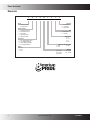
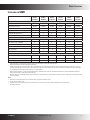
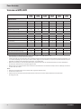
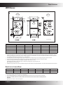
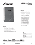
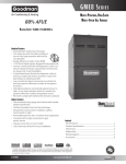
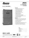
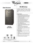
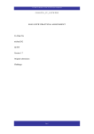
GMH95 & GCH95
®
Multi-Position, Two-Stage,
Multi-Speed Gas Furnaces
®
up to 95% AFUE
Standard Features
• Dual-diameter tubular heat exchanger
• Two-stage gas valve convertible technology allows installer
to activate the two-stage valve with the flip of a dipswitch
• 110V Silicon Nitride igniter designed for long igniter life
• Furnace control board with self-diagnostics, color-coded
low-voltage terminals, and provisions for electronic air
cleaner and 24-volt humidifiers
• Control board stores the last five diagnostic codes in
memory; simple push-button activation outputs the fault
history to a flashing red LED
• Low constant fan allows homeowner to activate the low
heat speed to efficiently circulate air throughout the home
• Self-adjusting feature automatically adjusts to high- or lowstage operation based on outside temperature without an
outdoor temperature sensor
• Dual-certified for sealed combustion direct vent (2-pipe)
or non-direct vent (1-pipe) applications
• All models comply with California NOx emissions standards
Cabinet Features
• Fully insulated, heavy-gauge steel cabinet with durable
baked-enamel finish
• Foil-faced insulation lines the heat exchanger
• Designed for multi-position installation:
GMH95: upflow, horizontal left or right;
GCH95/GCH9: downflow, horizontal left or right
• Easy-to-install top venting is standard; alternate flue/vent
located on the right (GMH95)
• Airtight solid bottom for side-return applications and easy-cut
tabs for effortless removal in bottom air inlet applications
• Convenient left or right connection for gas
and electric service
• Coil and furnace fit flush for most installations
Applies to 95% furnaces only.
Contents
Nomenclature..................................................................... 2
Product Specifications........................................................3
Dimensions.........................................................................5
Airflow Data........................................................................ 7
Wiring Diagrams.................................................................9
Accessories........................................................................14
* Complete warranty details available from your local dealer or at www.amana-hac.com. To receive
the Lifetime Heat Exchanger Limited Warranty (good for as long as you own your home), 10-Year
Unit Replacement Limited Warranty and 10-Year Parts Limited Warranty, online registration must be
completed within 60 days of installation. Online registration is not required in California or Québec.
SS-DGMH95
www.amana-hac.com
Amana® is a trademark of Maytag Corporation or its related companies and used under license to Goodman Company, L.P., Houston, Texas.
11/11
Supersedes 3/11
Product Specifications
Nomenclature
G
M
H
95
045
4
B
X
A
1
2
3
4,5
6,7,8
9
10
11
12
Brand
G Goodman® Brand
or Distinctions™
Revisions
A Initial Release
B 1st Revision
C 2nd Revision
Airflow Direction
C Downflow/Horizontal
D Dedicated Downflow
H High Airflow
K Dedicated Upflow
M Upflow/Horizontal
Description
V Two-Stage/Variable-speed
H Two-Stage/Multi-speed
S Single-Stage/Multi-speed
E Two-Stage/EEM Motor
AFUE
95 95%
9 93%+
8 80%
NOx
N Natural Gas
X Low NOx
Cabinet Width
A 14”
B 17½”
C 21”
D 24½”
Maximum CFM @ 0.5” ESP
3 1200
5 2000
4 1600
045: 45,000
070: 70,000
090: 90,000
MBTU/h
115: 115,000
140: 140,000
2www.amana-hac.com
SS-DGMH95
Product Specifications
Specifications for GMH95
GMH95
0453BXA
GMH95
0703BXA
GMH95
0704CXA
GMH95
0904CXA
GMH95
0905CXA
GMH95
1155DXA
Input¹
46,000
69,000
69,000
92,000
92,000
115,000
Natural Gas Output¹
44,600
66,400
66,400
89,000
88,400
110,500
LP Gas Output¹
39,330
58,995
58,995
78,660
78,660
98,325
95
95
95
95
95
95
Heating Capacity
AFUE²
Available AC @ 0.5” ESP
Temperature Rise Range (°F)
3
3
4
4
5
5
35 - 65
30 - 60
35 - 65
30 - 60
30 - 60
35 - 65
10” x 8”
10” x 8”
10” x 10”
10” x 10”
11” x 10”
11” x 10”
⅓
⅓
½
½
¾
¾
Circulator Blower
Size (D x W)
Horsepower @ 1075 RPM
Speed
4
4
4
4
4
4
Vent Diameter³
2”
2”
2”
2”
3”
3”
No. of Burners
2
3
3
4
4
5
580
580
770
770
960
960
Min. Circuit Ampacity⁴
9.4
9.4
13.8
13.8
13.2
13.2
Max. Overcurrent Device (amps)⁵
15
15
15
15
15
15
132
135
136
158
172
175
Disposable Filter Size (in²)
Electrical Data
Ship Weight (lbs)
¹
²
³
⁴
⁵
Natural Gas BTU/h. For altitudes above 2,000’, reduce input rating 4% for each 1,000’ above sea level.
DOE AFUE based upon Isolated Combustion System (ICS)
Installer must supply one or two PVC pipes: one for combustion air (optional) and one for the flue outlet (required). Vent pipe must be either 2” or 3” in
diameter, depending upon furnace input, number of elbows, length of run and installation (1 or 2 pipes). The optional Combustion Air Pipe is dependent
on installation/code requirements and must be 2” or 3” diameter PVC.
Minimum Circuit Ampacity = (1.25 x Circulator Blower Amps) + ID Blower amps. Wire size should be determined in accordance with National Electrical
Codes. Extensive wire runs will require larger wire sizes.
Maximum Overcurrent Protection Device refers to maximum recommended fuse or circuit breaker size. May use fuses or HACR-type circuit breakers of the
same size as noted.
Notes:
• All furnaces are manufactured for use on 115 VAC, 60 Hz, single-phase electrical supply.
• Gas Service Connection ½” FPT
• Important: Size fuses and wires properly and make electrical connections in accordance with the National Electrical Code and/or
all existing local codes.
SS-DGMH95www.amana-hac.com
3
Product Specifications
Specifications for GCH95/GCH9
GCH95
0453BX
GCH95
0703BX
GCH95
0704CX
GCH95
0904CX
GCH95
0905DX
GCH9
1155DX
Input¹
46,000
69,000
69,000
92,000
92,000
115,000
Natural Gas Output¹
43,700
65,550
65,550
87,400
87,400
106,500
LP Gas Output¹
39,330
58,995
58,995
78,660
78,660
96,255
95.0
95.0
95.0
95.0
95.0
93.0
3
3
4
4
5
5
25 - 55
35 - 65
25 - 55
40 - 70
35 - 65
40 - 70
Heating Capacity
AFUE²
Available AC @ 0.5” ESP
Temperature Rise Range (°F)
Circulator Blower
10” x 8”
10” x 8”
10” x 10”
10” x 10”
11” x 10”
11” x 10”
Horsepower @ 1075 RPM
Size (D x W)
⅓
⅓
½
½
¾
¾
Speed
4
4
4
4
4
4
Vent Diameter³
2”
2”
2”
2”
2”
2”
No. of Burners
2
3
3
4
4
5
576
564
564
752
752
940
9.8
9.8
12.9
12.9
13.4
13.2
Disposable Filter Size (in²)
Electrical Data
Min. Circuit Ampacity⁴
Max. Overcurrent Device (amps)⁵
15
15
15
15
15
15
Ship Weight (lbs)
132
135
135
156
173
175
¹
²
³
⁴
⁵
Natural Gas BTU/h. For altitudes above 2,000’, reduce input rating 4% for each 1,000’ above sea level.
DOE AFUE based upon Isolated Combustion System (ICS)
Installer must supply one or two PVC pipes: one for combustion air (optional) and one for the flue outlet (required). Vent pipe must be either 2” or
3” in diameter, depending upon furnace input, number of elbows, length of run and installation (1 or 2 pipes). The optional Combustion Air Pipe is
dependent on installation/code requirements and must be 2” or 3” diameter PVC.
Minimum Circuit Ampacity = (1.25 x Circulator Blower Amps) + ID Blower amps. Wire size should be determined in accordance with National
Electrical Codes. Extensive wire runs will require larger wire sizes.
Maximum Overcurrent Protection Device refers to maximum recommended fuse or circuit breaker size. May use fuses or HACR-type circuit breakers of the same size as noted.
Notes:
• All furnaces are manufactured for use on 115 VAC, 60 Hz, single-phase electrical supply.
• Gas Service Connection ½” FPT
• Important: Size fuses and wires properly and make electrical connections in accordance with the National Electrical Code and/or
all existing local codes.
4www.amana-hac.com
SS-DGMH95
Product Specifications
GMH95COMPONENT
Dimensions
IDENTIFICATION
GMH95*****XA*
AIR
DISCHARGE
AIR
DISCHARGE
19 7/8”
AIR
INTAKE
PIPE
2" PVC
RIGHT SIDE
DRAIN LINE
HOLES
1 1/2
2
1 5/8
1
UNFOLDED FLANGES
UNFOLDED FLANGES
FOLDED FLANGES
FOLDED FLANGES
RIGHT SIDE VIEW
Model
GMH950453BXA
GMH950703BXA
GMH950704CXA
GMH950904CXA
GMH950905CXA
GMH951155DXA
A
17½”
17½”
Cabinet Size
21”
21”
GMH950453BXA*
GMH950703BXA*
21”
24½”
B
16”
16”
A
19½”
19½”
17-1/2
19½”
23”
B
16
C
13⅛”
13⅛”
C
16⅛”
16⅛”
12-15/16
20⅝”
20⅝”
D
12-1/8
D
12⅛”
12⅛”
E
16”
16”
13-5/8
19⅜”
19⅜”
E
13⅝”
13⅝”
17½”
17½”
20⅞”
20⅞”
GMH950704CXA*
17-1/2
16
19-1/2
15-15/16
21
Notes:
GMH950904CXA*
• Installer must supply one or two PVC pipes: one for combustion air (optional) and one for the flue outlet (required). Vent pipe must be either 2” or 3” in
diameter, depending upon furnace input, number of elbows, length of run, and installation (1 or 2 pipes). The optional combustion air pipe is dependent
GMH950905DXA*
24-1/2 PVC. 23
20-7/8
19-3/8
20-7/16
on installation/code requirements GMH951155DXA*
and must be 2” or 3” diameter
• Line voltage wiring can enter through the right or left side of furnace. Low-voltage wiring can enter through the right or left side of furnace.
• Conversion kits for high-altitudeAll
natural
gas operation
are available. Contact your Goodman distributor or dealer for details.
dimensions
are in inches.
• Installer must supply the following gas line fittings, according to which entrance is used:
Left: One 90º street elbow; one 2½” pipe nipple; one 90º elbow; straight pipe; one ground joint union
Right: Straight pipe to reach gas valve
• Installations using a bottom return: Failure to unfold duct flanges will reduce airflow area by approximately 18%. This could result in performance and noise issues.
NOTE: Airflow area will be reduced by approximately 18% if duct flanges are not unfolded. This could cause performance issues and
noise issues.
Minimum Clearances to Combustible Materials
Position
Sides
Rear
Front
Bottom
Flue
Top
Upflow
Horizontal
0”
6”
0”
0”
1”
1”
C
C
0”
0”
1”
4”
6
•
•
•
•
C = If placed on combustible floor, the floor MUST be wood ONLY.
For servicing or cleaning, a 24” front clearance is recommended.
Unit connections (electrical, flue, and drain) may necessitate greater clearances than the minimum clearances listed above.
In all cases, accessibility clearance must take precedence over clearances from the enclosure where accessibility clearances
are greater.
• Approved for line contact in the horizontal position
SS-DGMH95www.amana-hac.com
5
Product Specifications
GCH95/GCH9 Dimensions
A
B
C
D
E
GCH950453BX
GCH950703BX
GCH950704CX
GCH950904CX
GCH950905DX
Model
17½”
17½”
21”
21”
24½”
16”
16”
19½”
19½”
23”
12⅜”
12⅜”
16⅜”
16⅜”
20⅜”
14½”
14½”
18”
18”
21½”
16”
16”
19½”
19½”
23”
GCH91155DX
24½”
23”
20⅜”
21½”
23”
Notes:
• Installer must supply one or two PVC pipes: one for combustion air (optional) and one for the flue outlet (required). Vent pipe must be either 2” or 3” in
diameter, depending upon furnace input, number of elbows, length of run, and installation (1 or 2 pipes). The optional combustion air pipe is dependent
on installation/code requirements and must be 2” or 3” diameter PVC.
• Line voltage wiring can enter through the right or left side of furnace. Low-voltage wiring can enter through the right or left side of furnace.
• Conversion kits for high-altitude natural gas operation are available. Contact your Goodman distributor or dealer for details.
• Installer must supply the following gas line fittings, according to which entrance is used:
Left: One 90º street elbow; one 2½” pipe nipple; one 90º elbow; straight pipe; one ground joint union
Right: Straight pipe to reach gas valve
• Installations using a bottom return: Failure to unfold duct flanges will reduce airflow area by approximately 18%. This could result in performance and
noise issues.
Minimum Clearances to Combustible Materials
Position
Downflow
Horizontal
Sides
Rear
Front
Bottom
Flue
Top
0”
6”
0”
0”
1”
1”
NC
C
0”
0”
1”
4”
C = Combustible: If placed on combustible floor, the floor MUST be wood ONLY.
NC = Non-Combustible: A combustible floor sub-base must be used for installation on combustible flooring
Notes:
• For servicing or cleaning, a 24” front clearance is recommended.
• Unit connections (electrical, flue and drain) may necessitate greater clearances than the minimum clearances listed below.
• In all cases, accessibility clearance must take precedence over clearances from the enclosure where accessibility clearances are greater.
6www.amana-hac.com
SS-DGMH95
Product Specifications
GMH95 Airflow Data
(CFM & Temperature Rise vs. External Static Pressure)
External Static Pressure, (Inches Water Column)
Model
GMH95
0453BXA
GMH95
0703BXA
GMH95
0704CXA
GMH95
0904CXA
GMH95
0905CXA
GMH95
1155DXA
Motor
Speed
Tons
AC¹
0.1
0.2
0.3
0.4
0.5
0.6
0.7
0.8
CFM
Rise
CFM
Rise
CFM
Rise
CFM
Rise
CFM
Rise
CFM
CFM
CFM
High
3
1,352
29
1,318
30
1,260
31
1,202
33
1,128
35
1,044
955
853
Med
2.5
1,214
32
1,172
34
1,123
35
1,064
37
1,012
39
938
859
741
Med-Lo
2
997
40
994
40
960
41
923
43
884
45
817
741
611
Low
1.5
757
52
753
52
734
54
704
56
674
59
620
524
438
High
3
1,449
41
1,409
42
1,326
45
1,273
47
1,201
49
1,194
1,136
1,018
Med
2.5
1,192
50
1,172
51
1,141
52
1,094
54
1,046
57
973
904
793
Med-Lo
2
981
61
962
62
943
63
917
65
888
67
830
764
665
Low
1.5
750
79
730
81
714
83
692
86
657
90
620
570
502
High
4
2,069
29
1,965
30
1,871
32
1,756
34
1,661
36
1,549
1,415
1,275
Med
3.5
1,752
34
1,724
34
1,667
36
1,603
37
1,488
40
1,402
1,290
1,082
Med-Lo
3
1,437
41
1,437
41
1,417
42
1,369
43
1,320
45
1,256
1,140
984
Low
2.5
1,184
50
1,177
50
1,161
51
1,132
52
1,095
54
1,047
928
837
High
4
1,970
40
1,874
42
1,757
45
1,667
48
1,566
51
1,431 1,334
Med
3.5
1,713
46
1,650
48
1,572
50
1,510
52
1,418
56
1,313
1,211 1,079
Med-Lo
3
1,439
55
1,412
56
1,370
58
1,327
60
1,260
63
1,166
1,078
956
Low
2.5
1,183
67
1,155
69
1,122
71
1,108
72
1,062
75
1,011
931
816
High
5
2,147
37
2,114
37
2,057
39
2,030
39
1,978
40
1,889
1,784
1,713
Med
4
1,675
47
1,686
47
1,640
48
1,623
49
1,557
51
1,501
1,455
1,360
Med-Lo
3.5
1,489
53
1,470
54
1,436
55
1,409
56
1,361
58
1,318
1,243
1,130
Low
3
1,307
61
1,265
63
1,234
64
1,203
66
1,168
68
1,096
1,053
991
High
5
2,134
46
2,103
47
2,029
48
1,941
51
1,906
51
1,818
1,733
1,625
Med
4
1,678
58
1,643
60
1,643
60
1,577
62
1,527
64
1,489
1,423
1,339
Med-Lo
3.5
1,453
68
1,440
68
1,426
69
1,363
72
1,349
73
1,314
1,253
1,205
Low
3
1,259
78
1,239
79
1,220
80
1,181
83
1,159
85
1,118
1,082
1,015
1,182
¹ @0.5” ESP
Notes:
• CFM in chart is without filter(s). Filters do not ship with this furnace, but must be provided by the installer.
• All furnaces ship as high-speed cooling and medium-speed heating. Installer must adjust blower cooling & heating speed as needed.
• For most applications, about 400 CFM per ton when cooling is desirable.
• INSTALLATION IS TO BE ADJUSTED TO OBTAIN TEMPERATURE RISE WITHIN THE RANGE SPECIFIED ON THE RATING PLATE.
• The chart is for information only. For satisfactory operation, external static pressure should not exceed value shown on the rating plate.
• The above chart is for furnaces installed at 0-2000 feet. At higher altitudes, a properly de-rated unit will have approximately the same temperature rise at a
particular CFM, while ESP at the CFM will be lower.
SS-DGMH95www.amana-hac.com
7
Product Specifications
GCH95/GCH9 Airflow Data
(CFM & Temperature Rise vs. External Static Pressure)
Model
Motor Tons
Speed AC¹
External Static Pressure, (Inches Water Column)
0.1
0.2
CFM
Rise
0.3
CFM
Rise
CFM
0.4
Rise
CFM
0.5
Rise
CFM
0.6
0.7
0.8
Rise
CFM
CFM
CFM
High
3
1,415
28
1,352
30
1,290
31
1,196
34
1,127
36
1,035
936
825
Med
2.5
1,221
33
1,178
34
1,127
36
1,073
38
1,007
40
932
834
733
2
1,034
39
1,000
40
976
41
935
43
881
46
818
733
662
Low
1.5
860
47
845
48
812
50
783
51
740
54
682
619
534
High
3
1,431
42
1,368
44
1,296
47
1,228
49
1,150
53
1,055
962
860
GCH95
0453BX Med-Lo
Med
GCH95
0703BX Med-Lo
2.5
1,212
50
1,182
51
1,138
53
1,091
55
1,019
59
944
871
769
2
1,002
60
978
62
956
63
921
66
878
69
825
738
647
Low
1.5
813
74
805
75
790
76
759
80
726
83
689
644
605
High
4
1,755
34
1,674
36
1,632
37
1,510
40
1,423
42
1,325
1,241
1,116
3.5
1,656
36
1,585
38
1,536
39
1,429
42
1,355
45
1,268
1,145
1,059
Med
GCH95
0704CX Med-Lo
Low
3
1,551
39
1,488
41
1,427
42
1,353
45
1,290
47
1,195
1,100
1,017
2.5
1,286
47
1,258
48
1,241
49
1,185
51
1,112
54
1,067
983
886
High
4
1,734
46
1,652
49
1,578
51
1,508
53
1,413
57
1,336
1,248
1,154
Med
3.5
1,642
49
1,558
52
1,487
54
1,418
57
1,336
60
1,243
1,164
1,039
3
1,522
53
1,458
55
1,396
58
1,321
61
1,253
64
1,182
1,101
986
Low
2.5
1,287
63
1,244
65
1,184
68
1,148
70
1,098
73
1,034
953
849
High
5
2,189
37
2,109
38
2,025
40
1,948
41
1,862
43
1,757
1,644
1,537
GCH95
0904CX Med-Lo
Med
GCH95
0905DX Med-Lo
Low
4
1,885
43
1,831
44
1,776
45
1,711
47
1,637
49
1,539
1,453
1,346
3.5
1,665
48
1,627
50
1,584
51
1,524
53
1,462
55
1,400
1,323
1,220
3
1,474
55
1,440
65
1,401
57
1,356
59
1,310
61
1,255
1,193
1,109
High
5
2,134
46
2,103
47
2,029
48
1,941
51
1,906
51
1,818
1,733
1,625
Med
4
1,678
58
1,643
60
1,643
60
1,577
62
1,527
64
1,489
1,423
1,339
GCH9
1155DX Med-Lo
Low
3.5
1,453
68
1,440
68
1,426
69
1,363
72
1,349
73
1,314
1,253
1,205
3
1,259
78
1,239
79
1,220
80
1,181
83
1,159
85
1,118
1,082
1,015
¹ @0.5” ESP
Notes:
• CFM in chart is without filter(s). Filters do not ship with this furnace, but must be provided by the installer. If the furnace requires two return filters, this
chart assumes both filters are installed.
• All furnaces ship as high-speed cooling and medium-speed heating. Installer must adjust blower cooling and heating speed as needed.
• For most jobs, about 400 CFM per ton when cooling is desirable.
• INSTALLATION IS TO BE ADJUSTED TO OBTAIN TEMPERATURE RISE WITHIN THE RANGE SPECIFIED ON THE RATING PLATE.
• This chart is for information only. For satisfactory operation, external static pressure should not exceed value shown on the rating plate.
• The above chart is for U.S. furnaces installed at 0-2000 feet. At higher altitudes, a properly derated unit will have approximately the same temperature rise
at a particular CFM, while ESP at the CFM will be lower.
8www.amana-hac.com
SS-DGMH95
Wiring is subject to change. Always
refer to the wiring diagram or the
unit for the most up-to-date wiring.
⚠ Warning
High Voltage: Disconnect all power before servicing or installing this unit. Multiple power
sources may be present. Failure to do so may cause property damage, personal injury, or death.
⚡
Product Specifications
GMH95 Wiring Diagram with Honeywell Valve
SS-DGMH95www.amana-hac.com
9
Product Specifications
OFF
2ND
STAGE
DELAY
BL
12
11
10
YL
W H
FS
BR
OR
GY
PU
EAC-H
5
IN D U C E D D R A F T
BLO W ER
WARNING:
DISCONNECT POWER
BEFORE SERVICING.
WIRING TO UNIT
MUST BE
PROPERLY
POLARIZED
AND GROUNDED.
WH
AUTO RESET
PRIMARY LIMIT
CONTROL
PU
BL
YL
OR
N
O
C
PK
RD
MANUAL RESET ROLLOUT LIMIT CONTROL(S)
( SINGLE CONTROL ON 45K BTU )
24 VAC
HUMIDIFIER
PM
N
O
C
GY
1
C
2
3
BR
(H O N E Y W E L L )
STEADY ON = NORMAL OPERATION
GND
FLAME
SENSOR
DISCONNECT
LOW VOLTAGE (24V)
= CONTROL FAILURE
1 FLASH
= SYSTEM LOCKOUT (RETRIES EXCEEDED)
2
2 FLASHES = PRESSURE SWITCH STUCK CLOSED
HI VOLTAGE (115V)
HI VOLTAGE FIELD
3 FLASHES = PRESSURE SWITCH STUCK OPEN
4 FLASHES = OPEN HIGH LIMIT
5
5 FLASHES = FLAME SENSE WITHOUT GAS VALVE
6
6 FLASHES = OPEN ROLLOUT OR OPEN FUSE
7
7 FLASHES = LOW FLAME SIGNAL
8
8 FLASHES = CHECK IGNITER OR IMPROPER GROUNDING
CONTINUOUS/RAPID FLASHES = REVERSED 115 VAC POLARITY
LOW VOLTAGE FIELD
JUNCTION
TERMINAL
INTERNAL TO
INTEGRATED CONTROL
PLUG CONNECTION
EQUIPMENT GND
FIELD GND
FIELD SPLICE
SWITCH (TEMP.)
IGNITER
3
3
4
L
BK
OFF
SWITCH (PRESS.)
OVERCURRENT
PROT. DEVICE
A
2
A5, D8
C8,B2
INITIAL RELEASE
DIM 9.670 WAS 10.00
COMPONENTS IN SCH
DELETED SHT 2
NOTES:
B
6. TO RECALL THE LAST 5 FAULTS, MOST RECENT TO LEAST RECENT, DEPRESS SWITCH FOR MORE THAN 2 SECONDS WHILE IN
STANDBY (NO THERMOSTAT INPUTS)
REV ZONE
4. IF HEATING AND COOLING BLOWER SPEEDS ARE NOT THE SAME, DISCARD JUMPER BEFORE CONNECTING BLOWER LEADS. UNUSED
BLOWER LEADS MUST BE PLACED ON "PARK" TERMINALS OF INTEGRATED CONTROL OR TAPED.
5. UNIT MUST BE PERMANENTLY GROUNDED AND CONFORM TO N.E.C. AND LOCAL CODES.
ECN
0904181
0904335
NOTES:
1. SET HEAT ANTICIPATOR ON ROOM THERMOSTAT AT 0.7 AMPS.
2. MANUFACTURER'S SPECIFIED REPLACEMENT PARTS MUST BE USED WHEN SERVICING.
3. IF ANY OF THE ORIGINAL WIRE AS SUPPLIED WITH THE FURNACE MUST BE REPLACED, IT MUST BE REPLACED WITH WIRING MATERIAL
HAVING A TEMPERATURE RATING OF AT LEAST 105 °C. USE COPPER CONDUCTORS ONLY.
B
1. MATERIAL: FLEXMARK PM 200 WHITE TC-245 L-23 SPEC 50K-8
10www.amana-hac.com
SS-DGMH95
WHITE POLYESTER FILM COATED WITH A PERMANENT PRESSURE
SENSITIVE ACRYLIC ADHESIVE AND BACKED WITH SEMI BLEACHED
KRAFT RELEASE LINER. UL FILE NO. MH10170. MATERIAL MUST
DE
THE GOODMAN MAN
DRAWING TO BE INTERPRETED IN
ACCORDANCE WITH ASME Y14.100
0140F00647 REV. B
N
WH
1
PK PINK
BR BROWN
WH WHITE
BL BLUE
GY GRAY
RD RED
WARNING:DISCONNECT POWER BEFORE
SERVICING.WIRING TO UNIT MUST BE
PROPERLY POLARIZED AND GROUNDED.
GR
OR
GAS VALVE
JUNCTION
BOX
BL
FRONT COVER
PRESSURE SWITCH
GY
GND
HI
N
4
2 CIRCUIT
CONNECTOR
GND
TO 115 VAC / 1Ø / 60HZ
POWER SUPPLY WITH
OVERCURRENT PROTECTION
DEVICE
ID B L O W E R
PRESSURE
S W IT C H
L
TO 115VAC/ 1 Ø /60 HZ POWER SUPPLY WITH
OVERCURRENT PROTECTION DEVICE
OR
WH
DISCONNECT
⚠ Warning
WH
WH
Wiring is subject to change. Always
refer to the wiring diagram or the
unit for the most up-to-date wiring.
B
9.670 ±.100
JUNCTION BOX
DOOR
SWITCH
BK
COLOR CODES:
YL YELLOW
OR ORANGE
PU PURPLE
GN GREEN
BK BLACK
ELECTRONIC
AIR CLEANER
LINE-H
GND
C
CIRCULATOR
BLWR
HI -H
AT
HE
6
COOL-H
INTEGRATED CONTROL MODULE
HE LO
AT
-H
BURNER COM PARTM ENT
0
ID
BLWR
IND
LINE NEUTRALS
INTEGRATED CONTROL MODULE
OR
OR
BL
WH
YL
RD
YL
WH
BK
BLO W ER CO M PARTM ENT
HOT
SURFACE
IGNITER
HOT SURFACE
IGNITER
IGN
C A P A C IT O R
RD
115 VAC
FLAME SENSOR
PK
RD
CIRCULATOR
BLOWER
BR
XFMR-H
GY
B K ( H I)
BL (MED)
OR (MED LOW)
RD (LOW)
BR
40 VA
TRANSFORMER
WH
GR
WH
MANUAL RESET ROLLOUT
LIMIT CONTROL(S)
(SINGLE CONTROL ON 45K BTU)
24 VAC
BK
LINE-H
SEE
NOTE 4
GND
RO2 (11)
TH (3)
1
HEAT-H
ID BLOWER
PRESSURE
SWITCH
RO1 (5)
GY
COOL-H
NO
C
AUTO RESET PRIMARY
LIMIT CONTROL
BR
PU
XFMR-H
2
115 VAC HOT AND PARK TERMINALS
HLO (1)
R
7
FS
SEE
NOTE 6
OR
OR
RD
GY
OR
*
GR
PSO (4)
HLI (7)
W
⚡
4
7
GY
FACTORY SETTINGS
SHOWN
DIAGNOSTIC
LED
5
8
115 VAC NEUTRAL
TERMINALS
*
*
*
OR
6
9
PS (10)
TO
MICRO
Y
C
NO
FRONT COVER
PRESSURE SWITCH
High Voltage: Disconnect all power before servicing or installing this unit. Multiple power
sources may be present. Failure to do so may cause property damage, personal injury, or death.
BK
IN T E G R A T E D
CONTROL
M O DULE
GY
PU
1
2
24V THERMOSTAT CONNECTIONS
3
G
8
MVL(2)
BK
OR
HEAT
OFF
DELAY
GAS
HI VALVE
PM
C
FUSE
MODE
C
GND
GND (8)
MVC (9)
WH
BK
ON
INTEGRATED
CONTROL MODULE
HUMIDIFIER
TR (6)
MVH (12) AUXILIARY LIMIT CONTROLS
W Y
R
G
B
C
40 VA
TRANSFORMER
115 VAC
B
( 6.000 )
( .125 )
(SEE NOTE 4)
GY
24 VAC
24V THERMOSTAT
CONNECTIONS
BLOWER
COMPARTMENT
DOOR SWITCH
(OPEN WHEN
DOOR OPEN)
OR
24 VAC
HUMIDIFIER
E
D
C
A
B
GCH95/GCH9115 Wiring Diagram with Honeywell Valve
Product Specifications
E
D
C
B
GMH95/GCH9 Wiring Diagram with White-Rodgers Valve
( 6.190 )
OFF
2ND
STAGE
DELAY
1
4
9
8
7
BL
12
11
10
YL
HEAT
OFF
DELAY
FS
2
COOL-H
HEAT-H
5
WARNING:
DISCONNECT POWER
BEFORE SERVICING.
WIRING TO UNIT
MUST BE
PROPERLY
POLARIZED
AND GROUNDED.
PU
YL
C
PK
BL
JUNCTION
BOX
GND
FLAME
SENSOR
STEADY ON = NORMAL OPERATION
DISCONNECT
LOW VOLTAGE (24V)
= CONTROL FAILURE
1
1 FLASH
= SYSTEM LOCKOUT (RETRIES EXCEEDED)
2
2 FLASHES = PRESSURE SWITCH STUCK CLOSED
HI VOLTAGE (115V)
HI VOLTAGE FIELD
5
5 FLASHES = FLAME SENSE WITHOUT GAS VALVE
6
6 FLASHES = OPEN ROLLOUT OR OPEN FUSE
7
7 FLASHES = LOW FLAME SIGNAL
8
8 FLASHES = CHECK IGNITER OR IMPROPER GROUNDING
CONTINUOUS/RAPID FLASHES = REVERSED 115 VAC POLARITY
C
JUNCTION
TERMINAL
INTERNAL TO
INTEGRATED CONTROL
PLUG CONNECTION
EQUIPMENT GND
FIELD GND
FIELD SPLICE
SWITCH (TEMP.)
IGNITER
SWITCH (PRESS.)
OVERCURRENT
PROT. DEVICE
A
B2
-
6. TO RECALL THE LAST 5 FAULTS, MOST RECENT TO LEAST RECENT, DEPRESS SWITCH FOR MORE THAN 2 SECONDS WHILE IN
STANDBY (NO THERMOSTAT INPUTS)
2
REV ZONE
B
4. IF HEATING AND COOLING BLOWER SPEEDS ARE NOT THE SAME, DISCARD JUMPER BEFORE CONNECTING BLOWER LEADS. UNUSED
BLOWER LEADS MUST BE PLACED ON "PARK" TERMINALS OF INTEGRATED CONTROL OR TAPED.
5. UNIT MUST BE PERMANENTLY GROUNDED AND CONFORM TO N.E.C. AND LOCAL CODES.
ECN
0903438
NOTES:
1. SET HEAT ANTICIPATOR ON ROOM THERMOSTAT AT 0.7 AMPS.
2. MANUFACTURER'S SPECIFIED REPLACEMENT PARTS MUST BE USED WHEN SERVICING.
3. IF ANY OF THE ORIGINAL WIRE AS SUPPLIED WITH THE FURNACE MUST BE REPLACED, IT MUST BE REPLACED WITH WIRING MATERIAL
HAVING A TEMPERATURE RATING OF AT LEAST 105 °C. USE COPPER CONDUCTORS ONLY.
0903747
PK PINK
BR BROWN
WH WHITE
BL BLUE
GY GRAY
RD RED
0140F00592 REV. B
INITIAL RELEASE
SHEET 1
UPDATED NOTE 1
NOTES:
1. MATERIAL: FLEXMARK PM 200 WHITE TC-245 L-23 SPEC 50K-8
SS-DGMH95www.amana-hac.com
B
WHITE POLYESTER FILM COATED WITH A PERMANENT PRESSURE
SENSITIVE ACRYLIC ADHESIVE AND BACKED WITH SEMI BLEACHED
KRAFT RELEASE LINER. UL FILE NO. MH10170. MATERIAL MUST
DE
THE GOODMAN MAN
COLOR CODES:
YL YELLOW
OR ORANGE
PU PURPLE
GN GREEN
BK BLACK
LOW VOLTAGE FIELD
3
3 FLASHES = PRESSURE SWITCH STUCK OPEN
4 FLASHES = OPEN HIGH LIMIT
L
BK
OFF
3
N
WH
OR
4
WARNING:DISCONNECT POWER BEFORE
SERVICING.WIRING TO UNIT MUST BE
PROPERLY POLARIZED AND GROUNDED.
GR
BR
GAS VALVE
N
4
2
3
GND
TO 115 VAC / 1Ø / 60HZ
POWER SUPPLY WITH
OVERCURRENT PROTECTION
DEVICE
0
GND
C
L
RD
MANUAL RESET ROLLOUT LIMIT CONTROL(S)
( SINGLE CONTROL ON 45K BTU )
24 VAC
HUMIDIFIER
FRONT COVER
PRESSURE SWITCH
N
C
O
PM 1
GY
GY
HI
DISCONNECT
TO 115VAC/ 1 Ø /60 HZ POWER SUPPLY WITH
OVERCURRENT PROTECTION DEVICE
OR
WH
6
JUNCTION BOX
BL
OR
ELECTRONIC
AIR CLEANER
DOOR
SWITCH
WH
AUTO RESET
PRIMARY LIMIT
CONTROL
INTEGRATED CONTROL MODULE
BR
IN D U C E D D R A F T
BLO W ER
CIRCULATOR
BLWR
HI -H
AT
HE
LINE-H
WH
WH
LINE NEUTRALS
INTEGRATED CONTROL MODULE
OR
10.500 ±.100
BK
HOT
SURFACE
IGNITER
COOL-H
EAC-H
GND
2 CIRCUIT
CONNECTOR
HE LO
AT
-H
MANUAL RESET
AUXILIARY LIMITS
(1) IN UPFLOW
BLOWER DECK
(2) IN C'FLOW
BLOWER HOUSING
BURNER COM PARTM ENT
ID B L O W E R
PRESSURE
S W IT C H
ID
BLWR
IND
PU
BLO W ER CO M PARTM ENT
N
O
HOT SURFACE
IGNITER
OR
WH
YL
GY
OR
BL
BK
C A P A C IT O R
RD
115 VAC
IGN
PK
RD
CIRCULATOR
BLOWER
BR
MANUAL RESET ROLLOUT
LIMIT CONTROL(S)
(SINGLE CONTROL ON 45K BTU)
24 VAC
FS
WH
BR
RO1 (5)
FLAME SENSOR
W H
YL
B K (H I)
BL (MED)
OR (MED LOW)
RD (LOW)
AUTO RESET
PRIMARY
LIMIT
CONTROL
RO2 (11)
XFMR-H
GR
RD
WH
MANUAL RESET AUXILIARY
LIMIT CONTROLS
R
BK
LINE-H
SEE
NOTE 4
GND
HLO (1)
40 VA
TRANSFORMER
WH
1
115 VAC HOT AND PARK TERMINALS
HLI (7)
W
PK
XFMR-H
SEE
NOTE 6
DIAGNOSTIC
LED
NO
C
PSO (4)
TH (3)
115 VAC NEUTRAL
TERMINALS
*
PS (10)
TO
MICRO
Y
BR
RD
GY
OR
*
GR
OR
OR
GY
FACTORY SETTINGS
SHOWN
OR
G
⚡
2
5
ID BLOWER
PRESSURE
SWITCH
7
MODE
*
*
GY
PK
3
6
C
NO
High Voltage: Disconnect all power before servicing or installing this unit. Multiple power
sources may be present. Failure to do so may cause property damage, personal injury, or death.
BK
FUSE
IN T E G R A T E D
CONTROL
M O DULE
24V THERMOSTAT CONNECTIONS
OR
PM
FRONT COVER
PRESSURE SWITCH
BK
WH
BK
ON
GAS
HI VALVE
MVL(2)
C
W Y
R
G
C
MVH (12)
⚠ Warning
115 VAC
GND
GND (8)
MVC (9)
Wiring is subject to change. Always
refer to the wiring diagram or the
unit for the most up-to-date wiring.
C
40 VA
TRANSFORMER
INTEGRATED
CONTROL MODULE
HUMIDIFIER
TR (6)
8
( .125 )
(SEE NOTE 4)
GY
24 VAC
24V THERMOSTAT
CONNECTIONS
BLOWER
COMPARTMENT
DOOR SWITCH
(OPEN WHEN
DOOR OPEN)
OR
24 VAC
HUMIDIFIER
11
200 WHITE TC-245 WITH
HESIVE AS PER SPEC
7
GCH95 Wiring Diagram with White-Rodgers Valve
( 6.000 )
MVH (12) AUXILIARY LIMIT CONTROLS
C
W Y
R
G
MVL(2)
BK
3
IN T E G R A T E D
CONTROL
M O DULE
OFF
2ND
STAGE
DELAY
MODE
HEAT
OFF
DELAY
4
7
BL
12
11
10
YL
RO2 (11)
W H
FS
HE LO
AT
-H
COOL-H
BR
CIRCULATOR
BLWR
GY
EAC-H
4
OR
HI -H
AT
HE
INTEGRATED CONTROL MODULE
ID
BLWR
IND
LINE NEUTRALS
OR
OR
BL
WH
PU
RD
YL
BK
YL
INTEGRATED CONTROL MODULE
GR
GY
9.670 ±.100
BURNER COM PARTM ENT
ELECTRONIC
AIR CLEANER
LINE-H
JUNCTION BOX
GND
DOOR
SWITCH
BK
WH
WH
IN D U C E D D R A F T
BLO W ER
WARNING:
DISCONNECT POWER
BEFORE SERVICING.
WIRING TO UNIT
MUST BE
PROPERLY
POLARIZED
AND GROUNDED.
WH
PU
BL
YL
OR
N
O
PK
GND
BR
STEADY ON = NORMAL OPERATION
L
BK
DISCONNECT
LOW VOLTAGE (24V)
= CONTROL FAILURE
1
1 FLASH
= SYSTEM LOCKOUT (RETRIES EXCEEDED)
2
2 FLASHES = PRESSURE SWITCH STUCK CLOSED
HI VOLTAGE (115V)
HI VOLTAGE FIELD
3
3 FLASHES = PRESSURE SWITCH STUCK OPEN
4
4 FLASHES = OPEN HIGH LIMIT
5
5 FLASHES = FLAME SENSE WITHOUT GAS VALVE
6
6 FLASHES = OPEN ROLLOUT OR OPEN FUSE
LOW VOLTAGE FIELD
JUNCTION
TERMINAL
7
7 FLASHES = LOW FLAME SIGNAL
8
8 FLASHES = CHECK IGNITER OR IMPROPER GROUNDING
CONTINUOUS/RAPID FLASHES = REVERSED 115 VAC POLARITY
IGNITER
SWITCH (PRESS.)
OVERCURRENT
PROT. DEVICE
NOTES:
1. SET HEAT ANTICIPATOR ON ROOM THERMOSTAT AT 0.7 AMPS.
2. MANUFACTURER'S SPECIFIED REPLACEMENT PARTS MUST BE USED WHEN SERVICING.
3. IF ANY OF THE ORIGINAL WIRE AS SUPPLIED WITH THE FURNACE MUST BE REPLACED, IT MUST BE REPLACED WITH WIRING MATERIAL
HAVING A TEMPERATURE RATING OF AT LEAST 105 °C. USE COPPER CONDUCTORS ONLY.
4. IF HEATING AND COOLING BLOWER SPEEDS ARE NOT THE SAME, DISCARD JUMPER BEFORE CONNECTING BLOWER LEADS. UNUSED
6. TO RECALL THE LAST 5 FAULTS, MOST RECENT TO LEAST RECENT, DEPRESS SWITCH FOR MORE THAN 2 SECONDS WHILE IN
STANDBY (NO THERMOSTAT INPUTS)
DATE
BLOWER LEADS MUST BE PLACED ON "PARK" TERMINALS OF INTEGRATED CONTROL OR TAPED.
5. UNIT MUST BE PERMANENTLY GROUNDED AND CONFORM TO N.E.C. AND LOCAL CODES.
1
0140F00674 REV. A
SWITCH (TEMP.)
DTM RP 10-19-09
PK PINK
BR BROWN
WH WHITE
BL BLUE
GY GRAY
RD RED
PLUG CONNECTION
FIELD GND
FIELD SPLICE
CHK DR
COLOR CODES:
YL YELLOW
OR ORANGE
PU PURPLE
GN GREEN
BK BLACK
INTERNAL TO
INTEGRATED CONTROL
EQUIPMENT GND
DESCRIPTION
OFF
2
FLAME
SENSOR
OR
INITIAL RELEASE
GAS VALVE
N
WH
-
2
3
WARNING:DISCONNECT POWER BEFORE
SERVICING.WIRING TO UNIT MUST BE
PROPERLY POLARIZED AND GROUNDED.
A
C
JUNCTION
BOX
GR
GND
HI
BL
REV ZONE
HOT
SURFACE
IGNITER
RD
MANUAL RESET ROLLOUT LIMIT CONTROL(S)
( SINGLE CONTROL ON 45K BTU )
24 VAC
HUMIDIFIER
FRONT COVER
PRESSURE SWITCH
N
C
O
PM 1
GY
GY
ECN
THE GOODMAN MANUFACTURING COMPANY, L.P.
2 CIRCUIT
CONNECTOR
N
TO 115 VAC / 1Ø / 60HZ
POWER SUPPLY WITH
OVERCURRENT PROTECTION
DEVICE
ID B L O W E R
PRESSURE
S W IT C H
GND
0904356
WH
L
TO 115VAC/ 1 Ø /60 HZ POWER SUPPLY WITH
OVERCURRENT PROTECTION DEVICE
OR
C
DISCONNECT
3
AUTO RESET
PRIMARY LIMIT
CONTROL
C
HOT SURFACE
IGNITER
IGN
PK
RD
5
115 VAC
FLAME SENSOR
BLO W ER CO M PARTM ENT
0
MANUAL RESET ROLLOUT
LIMIT CONTROL(S)
(SINGLE CONTROL ON 45K BTU)
24 VAC
XFMR-H
C A P A C IT O R
RD
ID BLOWER
PRESSURE
SWITCH
RO1 (5)
BK
CIRCULATOR
BLOWER
BR
WH
WH
BR
NO
C
AUTO RESET PRIMARY
LIMIT CONTROL
R
TH (3)
1
LINE-H
B K ( H I)
BL (MED)
OR (MED LOW)
RD (LOW)
HLO (1)
GY
2
SEE
NOTE 4
WH
HLI (7)
W
40 VA
TRANSFORMER
HEAT-H
GND
PSO (4)
TO
MICRO
Y
C
NO
FRONT COVER
PRESSURE SWITCH
PS (10)
BR
PU
XFMR-H
COOL-H
OR
FS
115 VAC HOT AND PARK TERMINALS
GR
OR
RD
GY
OR
*
SEE
NOTE 6
DIAGNOSTIC
LED
5
8
GY
FACTORY SETTINGS
SHOWN
OR
6
9
115 VAC NEUTRAL
TERMINALS
*
*
*
GY
PU
1
2
24V THERMOSTAT CONNECTIONS
OR
FUSE
G
6
BK
WH
BK
ON
GAS
HI VALVE
PM
⚡
115 VAC
C
GND
GND (8)
MVC (9)
High Voltage: Disconnect all power before servicing or installing this unit. Multiple power
sources may be present. Failure to do so may cause property damage, personal injury, or death.
C
40 VA
TRANSFORMER
INTEGRATED
CONTROL MODULE
HUMIDIFIER
TR (6)
⚠ Warning
( .125 )
(SEE NOTE 4)
GY
24 VAC
24V THERMOSTAT
CONNECTIONS
BLOWER
COMPARTMENT
DOOR SWITCH
(OPEN WHEN
DOOR OPEN)
OR
24 VAC
HUMIDIFIER
Wiring is subject to change. Always
refer to the wiring diagram or the
unit for the most up-to-date wiring.
ON WHITE BACKGROUND.
AGRAM REMAINS UNCHANGED UNTIL
CHANGED.
Product Specifications
E
D
C
B
12www.amana-hac.com
SS-DGMH95
Product Specifications
TwinComfort™ Configuration & Operation
TwinComfort™
This furnace is capable of the following heating modes:
• Single Stage (Factory Setting)
• Modified Two-Stage
• Fixed 5-Min Low Stage
• Auto Time (1-12 Min) Low Stage
To change from the factory single-stage operation, adjust the
dipswitches on the ignition control as follows:
Mode
Off On
5 Min
Mode Dipswitch
Fixed
2nd Stage Delay
Auto
Dipswitch
Note: This furnace is designed to be used with a single-stage
room thermostat.
Start
Start
Call for Heat
Call for Heat
Safety Circuit Check
Safety Circuit Check
Start Furnace
in Low Stage
Start Furnace
in Low Stage
Low-Heat Blower
Low-Heat Blower
Delay Time (5 Min)
Delay Time (1-12 Min)
Gas Valve Switch
to 2nd Stage
Gas Valve Switch
to 2nd Stage
Blower Switch to
Hi Heat Operation
Blower Switch to
Hi Heat Operation
T-Stat Satisfied
T-Stat Satisfied
Thermostats
Model
Description
CHT18-60
Cooling/Heating, Mechanical
CH70TG
Cooling/Heating, Digital, Non-programmable
CHSATG
Cooling/Heating, Mechanical
H20TWR
Heating Only, Mechanical
SS-DGMH95www.amana-hac.com
13
Product Specifications
Accessories
Accessory
Description
GMH95
0453BXA
GMH95
0703BXA
GMH95
0704CXA
GMH95
0904CXA
GMH95
0905CXA
GMH95
1155DXA
LPM-05
LP Conversion Kit (Springs & Orifice)¹
√
√
√
√
√
√
LPM-06
LP Conversion Kit (Springs & Orifice)²
√
√
√
√
√
√
LPLP01
LP Gas Low-Pressure Kit
√
√
√
√
√
√
GSAS
Electronic Air Cleaners (-10, -11, -12, -18)
√
√
√
√
√
√
GMU
Media Air Cleaners (1620, 2020, 1625, 2025)
√
√
√
√
√
√
HANG11
High Altitude Natural Gas Kit
1
1
1
1
1
1
HANG12
High Altitude Natural Gas Kit
2
2
2
2
2
2
HALP10
High Altitude LP Gas Kit
3
3
3
3
3
3
HAPS27
High Altitude Pressure Switch Kit
3
3
3
3
3
3
FTK04
Twinning Kit
√
√
√
√
√
√
EFR01
External Filter Rack
√
√
√
√
√
√
DCVK-20
Horizontal/Vertical Concentric Vent Kit (2”)
√
√
---
---
---
---
DCVK-30
Horizontal/Vertical Concentric Vent Kit (3”)
√
√
√
√
√
√
0170K00000S
Flush-mount Vent Kit
√
√
√
√
√
√
¹
²
√
1
2
3
White-Rodgers valves only
White-Rodgers and Honeywell valves
Indicates accessories available for this model
Indicates 7,001’ to 9,000’ altitude
Indicates 9,001’ to 11,000’ altitude
Indicates 7,001’ to 11,000’ altitude
Notes
• All installations above 7,000’ require a pressure switch change. For installation in Canada, furnaces are certified only to 4,500’.
• Downflow Floor base: When the GCH9 model is installed directly on a wood floor, a downflow floor base must be used. Those model numbers are: CFB17,
CFB21 and CFB24.
14www.amana-hac.com
SS-DGMH95
Product Specifications
Accessories
Accessory
Description
GCH95
0453BXA
GCH95
0703BXA
GCH95
0704CXA
GCH95
0904CXA
GCH95
0905CXA
GCH9
1155DXA
LPM-05
LP Conversion Kit (Springs & Orifice)¹
√
√
√
√
√
√
LPM-06
LP Conversion Kit (Springs & Orifice)²
√
√
√
√
√
√
LPLP01
LP Gas Low-Pressure Kit
GSAS
Electronic Air Cleaners (-10, -11, -12, -18)
√
√
√
√
√
√
GMU
Media Air Cleaners (1620, 2020, 1625, 2025)
√
√
√
√
√
√
HANG11
High Altitude Natural Gas Kit
1
1
1
1
1
1
HANG12
High Altitude Natural Gas Kit
2
2
2
2
2
2
HALP10
High Altitude LP Gas Kit
3
3
3
3
3
3
HAPS27
High Altitude Pressure Switch Kit
3
3
3
3
3
3
EFR01
External Filter Rack
√
√
√
√
√
√
DCVK-20
Horizontal/Vertical Concentric Vent Kit (2”)
√
√
---
---
---
---
DCVK-30
Horizontal/Vertical Concentric Vent Kit (3”)
√
√
√
√
√
√
0170K00000S
Flush-mount Vent Kit
√
√
√
√
√
√
¹
²
√
1
2
3
√
White-Rodgers valves only
White-Rodgers and Honeywell valves
Indicates accessories available for this model
Indicates 7,001’ to 9,000’ altitude
Indicates 9,001’ to 11,000’ altitude
Indicates 7,001’ to 11,000’ altitude
Notes
• All installations above 7,000’ require a pressure switch change. For installation in Canada, furnaces are certified only to 4,500’.
• Downflow Floor base: When the GCH9 model is installed directly on a wood floor, a downflow floor base must be used. Those model numbers are: CFB17,
CFB21 and CFB24.
SS-DGMH95www.amana-hac.com
15
Product Specifications
Notes
Amana® is a trademark of Maytag Corporation or its related companies and used under license to Goodman Company, L.P. All rights reserved. Our continuing commitment to quality products may mean a change in specifications without notice. © 2011 • Goodman Company, L.P. • Houston, Texas • Printed in the USA.
16www.amana-hac.com
SS-DGMH95