1
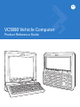
VC5090 Vehicle Computer
Product Reference Guide
VC5090 Vehicle Computer
Product Reference Guide
72E-76347-02
Revision A
August 2007
ii
VC5090 Vehicle Computer Product Reference Guide
© 2006-7 by Motorola, Inc. All rights reserved.
No part of this publication may be reproduced or used in any form, or by any electrical or mechanical means,
without permission in writing from Motorola. This includes electronic or mechanical means, such as
photocopying, recording, or information storage and retrieval systems. The material in this manual is subject to
change without notice.
The software is provided strictly on an “as is” basis. All software, including firmware, furnished to the user is on
a licensed basis. Motorola grants to the user a non-transferable and non-exclusive license to use each
software or firmware program delivered hereunder (licensed program). Except as noted below, such license
may not be assigned, sublicensed, or otherwise transferred by the user without prior written consent of
Motorola. No right to copy a licensed program in whole or in part is granted, except as permitted under
copyright law. The user shall not modify, merge, or incorporate any form or portion of a licensed program with
other program material, create a derivative work from a licensed program, or use a licensed program in a
network without written permission from Motorola. The user agrees to maintain Motorola’s copyright notice on
the licensed programs delivered hereunder, and to include the same on any authorized copies it makes, in
whole or in part. The user agrees not to decompile, disassemble, decode, or reverse engineer any licensed
program delivered to the user or any portion thereof.
Motorola reserves the right to make changes to any software or product to improve reliability, function, or
design.
Motorola does not assume any product liability arising out of, or in connection with, the application or use of
any product, circuit, or application described herein.
No license is granted, either expressly or by implication, estoppel, or otherwise under any Motorola, Inc.,
intellectual property rights. An implied license only exists for equipment, circuits, and subsystems contained in
Motorola products.
MOTOROLA and the Stylized M Logo and Symbol and the Symbol logo are registered in the US Patent &
Trademark Office. Bluetooth is a registered trademark of Bluetooth SIG. Microsoft, Windows and ActiveSync
are either registered trademarks or trademarks of Microsoft Corporation. All other product or service names
are the property of their respective owners.
Motorola, Inc.
One Motorola Plaza
Holtsville, New York 11742-1300
http://www.symbol.com
Patents
This product is covered by one or more of the patents listed on the web site: http://www.symbol.com/patents.
Warranty
Subject to the terms of Motorola’s hardware warranty statement, the VC5090 Vehicle Computer products are
warranted against defects in workmanship and materials for a period of one year from the date of shipment.
For the complete Motorola hardware product warranty statement, go to: http://www.symbol.com/warranty.
iii
Revision History
Changes to the original manual are listed below:
Change
Date
Description
-01 Rev A
5/31/06
Initial release.
-02 Rev A
08/10/07
Updates including: Fusion 2.5, latest OS, AZERTY keyboard, mounting instructions,
SCM and registry settings, maintenance release (BSP26).
iv
VC5090 Vehicle Computer Product Reference Guide
Table of Contents
Patents.................................................................................................................................................. ii
Warranty ............................................................................................................................................... ii
Revision History.................................................................................................................................... iii
About This Guide
Introduction ...........................................................................................................................................
Documentation Set .........................................................................................................................
Configurations.......................................................................................................................................
Software Versions...........................................................................................................................
Chapter Descriptions ............................................................................................................................
Notational Conventions.........................................................................................................................
Related Documents and Software ........................................................................................................
Service Information...............................................................................................................................
Returning the Vehicle Computer for Service...................................................................................
xiii
xiii
xiv
xiv
xv
xv
xvi
xvi
xvii
Chapter 1: Getting Started
Introduction ..........................................................................................................................................
Unpacking the VC5090 ........................................................................................................................
Features ...............................................................................................................................................
Accessories .........................................................................................................................................
Third Party Accessories .......................................................................................................................
Getting Started .....................................................................................................................................
Installing the Desiccant Bag ...........................................................................................................
Installing the Vehicle Computer .....................................................................................................
Charging the Memory Backup Battery ...........................................................................................
Starting the Vehicle Computer .......................................................................................................
1-1
1-1
1-2
1-4
1-6
1-7
1-7
1-8
1-8
1-8
Chapter 2: Installation
Introduction ..........................................................................................................................................
Installing the Mounting Bracket ............................................................................................................
Installing the VC5090 in a Forklift ........................................................................................................
Positioning the Vehicle Computer ..................................................................................................
2-1
2-2
2-3
2-3
vi
VC5090 Vehicle Computer Product Reference Guide
Mounting the Vehicle Computer .....................................................................................................
Mounting Bracket Template .....................................................................................................
Mounting onto an Over-Head Cross-Beam Example ...............................................................
Mounting onto an Over-Head Cage Example ..........................................................................
Mounting on a Dashboard or Horizontal Surface Example ......................................................
Routing Electrical Cables .........................................................................................................
12 Volt Propane Forklifts ..........................................................................................................
Electric Forklifts ........................................................................................................................
Removing Power to the Vehicle Computer ....................................................................................
Installing the VC5090 on a Desktop ....................................................................................................
Mounting the Bracket on a Desktop ...............................................................................................
Connecting the Vehicle Computer to AC Power ............................................................................
Installing the Optional Keyboard ..........................................................................................................
Adjusting the Keyboard ..................................................................................................................
Installing a Scanner .............................................................................................................................
Connecting an LS3203 or a DS/LS3408 Serial Scanner ...............................................................
Connecting an DS/LS3408 USB Scanner ......................................................................................
Connecting an DS/LS3478 Serial Scanner ....................................................................................
Connecting a DS/LS3478 USB Scanner ........................................................................................
Connecting an LS3578 Bluetooth Scanner ....................................................................................
Scanner Setup ...............................................................................................................................
Enable/Disable the Scanner ..........................................................................................................
Verifying the Scanner is Working Properly ....................................................................................
Pairing Bluetooth Scanner and Cradle ...........................................................................................
Installing the Uninterruptable Power Supply ........................................................................................
Installing a Secure Digital Card ...........................................................................................................
Installing a External Antenna ...............................................................................................................
Installing the Vehicle In-Motion Detector .............................................................................................
Normally Closed Switch .................................................................................................................
Normally Open Switch ...................................................................................................................
Operation .......................................................................................................................................
Switches .........................................................................................................................................
Cable Installation ...........................................................................................................................
Over-Ride .......................................................................................................................................
Connecting Accessories ......................................................................................................................
Connecting an External Speaker to the Vehicle Computer .................................................................
Chapter 3: Operating the VC5090
Introduction ..........................................................................................................................................
Quick Access Panel .............................................................................................................................
Power Button .................................................................................................................................
Power LED .....................................................................................................................................
COMM LED ....................................................................................................................................
Backlight Control Button ................................................................................................................
Programmable (“P”) Keys ..............................................................................................................
Launch Application ...................................................................................................................
Simulate KeyPress ...................................................................................................................
Play Key Sequence ..................................................................................................................
Using the Keyboard .............................................................................................................................
2-5
2-5
2-6
2-7
2-8
2-9
2-10
2-11
2-13
2-15
2-15
2-16
2-17
2-18
2-21
2-21
2-22
2-24
2-25
2-26
2-28
2-30
2-31
2-31
2-32
2-34
2-36
2-37
2-37
2-37
2-37
2-38
2-39
2-42
2-43
2-43
3-1
3-1
3-1
3-2
3-2
3-3
3-3
3-4
3-4
3-5
3-5
Table of Contents
vii
Keyboard Functionality ..................................................................................................................
Soft Keyboards ..............................................................................................................................
Adjusting the Brightness ......................................................................................................................
Controlling Screen Brightness .......................................................................................................
Controlling Keyboard Backlight ......................................................................................................
Adjusting the Volume ...........................................................................................................................
Taskbar ................................................................................................................................................
Start Button ....................................................................................................................................
Programs Menu .............................................................................................................................
Desktop Button ..............................................................................................................................
Task Manager and Properties ........................................................................................................
Task Manager ..........................................................................................................................
Properties .................................................................................................................................
Using a Headset ..................................................................................................................................
Resetting the Vehicle Computer ..........................................................................................................
Performing a Warm Boot ...............................................................................................................
Performing a Cold Boot ..................................................................................................................
Methods of Suspension .................................................................................................................
Critical Suspension ........................................................................................................................
Waking the Vehicle Computer .......................................................................................................
Calibrating the Screen .........................................................................................................................
Using the Display ...........................................................................................................................
Using the Keyboard .......................................................................................................................
Checking Battery Status ......................................................................................................................
Ignition Sensing ...................................................................................................................................
3-5
3-6
3-9
3-9
3-10
3-10
3-10
3-12
3-13
3-13
3-13
3-13
3-14
3-15
3-16
3-16
3-16
3-16
3-16
3-17
3-18
3-18
3-19
3-22
3-22
Chapter 4: Wireless Applications
Introduction ..........................................................................................................................................
Signal Strength Icon ............................................................................................................................
Turning the WLAN Radio On and Off ..................................................................................................
With Fusion 2.0 ..............................................................................................................................
With Fusion 2.5 ..............................................................................................................................
Find WLANs Application ......................................................................................................................
Profile Editor Wizard ............................................................................................................................
Profile ID ........................................................................................................................................
Operating Mode .............................................................................................................................
Ad-Hoc ...........................................................................................................................................
Authentication ................................................................................................................................
Tunneled Authentication ................................................................................................................
User Certificate Selection ..............................................................................................................
User Certificate Installation ......................................................................................................
Server Certificate Selection ...........................................................................................................
Credential Cache Options ..............................................................................................................
User Name ...............................................................................................................................
Password .......................................................................................................................................
Advanced Identity ..........................................................................................................................
Encryption ......................................................................................................................................
Key Entry Page ........................................................................................................................
Passkey Dialog ........................................................................................................................
4-1
4-2
4-2
4-2
4-3
4-4
4-5
4-5
4-6
4-7
4-8
4-9
4-11
4-11
4-11
4-12
4-14
4-15
4-15
4-16
4-17
4-17
viii
VC5090 Vehicle Computer Product Reference Guide
IP Mode ..........................................................................................................................................
IP Address Entry ............................................................................................................................
Transmit Power ..............................................................................................................................
Battery Usage ................................................................................................................................
Manage Profiles Application ..........................................................................................................
Changing Profiles .....................................................................................................................
Editing a Profile ........................................................................................................................
Creating a New Profile .............................................................................................................
Deleting a Profile ......................................................................................................................
Ordering Profiles ......................................................................................................................
Export a Profile ........................................................................................................................
Wireless Status Application .................................................................................................................
Signal Strength Window .................................................................................................................
Current Profile Window ..................................................................................................................
IPv4 Status Window .......................................................................................................................
Wireless Log Window ....................................................................................................................
Saving a Log ............................................................................................................................
Clearing the Log .......................................................................................................................
Versions Window ...........................................................................................................................
Wireless Diagnostics Application .........................................................................................................
ICMP Ping Window ........................................................................................................................
Trace Route Window .....................................................................................................................
Known APs Window .......................................................................................................................
Options ................................................................................................................................................
Operating Mode Filtering ...............................................................................................................
Regulatory Options ........................................................................................................................
Band Selection ...............................................................................................................................
System Options ..............................................................................................................................
Change Password ..........................................................................................................................
Export .............................................................................................................................................
Cold Boot Persistence .........................................................................................................................
Registry Settings ..................................................................................................................................
Log On/Off Application .........................................................................................................................
User Already Logged In .................................................................................................................
No User Logged In .........................................................................................................................
Chapter 5: Using Bluetooth
Introduction ..........................................................................................................................................
Adaptive Frequency Hopping ..............................................................................................................
Security ................................................................................................................................................
Turning the Bluetooth Radio Mode On and Off ...................................................................................
Disabling Bluetooth ........................................................................................................................
Enabling Bluetooth .........................................................................................................................
Bluetooth Power States .................................................................................................................
Cold Boot .................................................................................................................................
Warm Boot ...............................................................................................................................
Suspend ...................................................................................................................................
Resume ....................................................................................................................................
Bluetooth Profiles .................................................................................................................................
4-18
4-18
4-19
4-21
4-22
4-23
4-23
4-23
4-24
4-24
4-24
4-25
4-25
4-27
4-27
4-29
4-29
4-29
4-29
4-30
4-31
4-31
4-32
4-33
4-33
4-34
4-34
4-35
4-35
4-36
4-37
4-38
4-38
4-38
4-38
5-1
5-1
5-2
5-2
5-2
5-2
5-3
5-3
5-3
5-3
5-3
5-3
Table of Contents
Modes ..................................................................................................................................................
Wizard Mode ..................................................................................................................................
Explorer Mode ................................................................................................................................
Discovering Bluetooth Device(s) ..........................................................................................................
Bonding with Discovered Device(s) .........................................................................................
Renaming a Bonded Device ....................................................................................................
Deleting a Bonded Device .......................................................................................................
Accepting a Bond .....................................................................................................................
Discovering Services ...........................................................................................................................
File Transfer Services ....................................................................................................................
Create New File or Folder ........................................................................................................
Delete File ................................................................................................................................
Get File ....................................................................................................................................
Put File .....................................................................................................................................
Connect to Internet Using Access Point ........................................................................................
OBEX Object Push Services ..........................................................................................................
Send a Picture .........................................................................................................................
Headset Services ...........................................................................................................................
Serial Port Services .......................................................................................................................
Personal Area Network Services ...................................................................................................
Bluetooth Settings ................................................................................................................................
Device Info Tab ..............................................................................................................................
Services Tab ..................................................................................................................................
File Transfer Service ................................................................................................................
OBEX Object Push Service .....................................................................................................
Personal Area Networking Service ..........................................................................................
Serial Port Service ...................................................................................................................
Headset Service .......................................................................................................................
Security Tab ...................................................................................................................................
Discovery Tab ................................................................................................................................
Virtual COM Port Tab .....................................................................................................................
Miscellaneous Tab .........................................................................................................................
ix
5-5
5-5
5-7
5-8
5-9
5-10
5-11
5-12
5-13
5-14
5-14
5-15
5-15
5-15
5-15
5-15
5-16
5-17
5-18
5-18
5-19
5-19
5-19
5-20
5-21
5-22
5-22
5-23
5-23
5-24
5-24
5-25
Chapter 6: ActiveSync
Introduction ..........................................................................................................................................
Installing ActiveSync ............................................................................................................................
Mobile Computer Setup .......................................................................................................................
Setting Up an ActiveSync Connection on the Host Computer .............................................................
Setting up a Partnership ................................................................................................................
6-1
6-2
6-2
6-3
6-3
Chapter 7: Application Development and Deployment
Introduction ..........................................................................................................................................
Software Installation on Development PC (Application Development) ................................................
Device Configuration Package .......................................................................................................
Platform SDK .................................................................................................................................
Symbol Mobility Developer Kit .......................................................................................................
Installing Other Development Software .........................................................................................
Software Installation on Vehicle Computer ..........................................................................................
7-1
7-1
7-1
7-2
7-2
7-3
7-3
x
VC5090 Vehicle Computer Product Reference Guide
ActiveSync .....................................................................................................................................
SD Card .........................................................................................................................................
IPL ..................................................................................................................................................
Creating and Loading Hex Images ......................................................................................................
Starting Terminal Configuration Manager ......................................................................................
Defining Script Properties ..............................................................................................................
Creating the Script for the Hex Image ............................................................................................
Opening a New or Existing Script ............................................................................................
Updating TCM 1.X Scripts .......................................................................................................
Copying Components to the Script ..........................................................................................
Saving the Script ......................................................................................................................
Building the Image .........................................................................................................................
Sending the Hex Image .......................................................................................................................
Using TCM .....................................................................................................................................
Using SD Card ...............................................................................................................................
TCM Error Messages ...........................................................................................................................
IPL Error Detection ..............................................................................................................................
Creating a Splash Screen ....................................................................................................................
Splash Screen Format ...................................................................................................................
Flash Storage ......................................................................................................................................
FFS Partitions ................................................................................................................................
Working with FFS Partitions ...........................................................................................................
RegMerge.dll ............................................................................................................................
CopyFiles .................................................................................................................................
Non-FFS Partitions ........................................................................................................................
Downloading Partitions to the Vehicle Computer ...........................................................................
7-3
7-4
7-4
7-6
7-6
7-8
7-9
7-9
7-9
7-10
7-10
7-10
7-11
7-11
7-15
7-18
7-20
7-22
7-22
7-22
7-22
7-23
7-23
7-23
7-24
7-24
Chapter 8: Staging and Provisioning
Introduction ..........................................................................................................................................
Staging .................................................................................................................................................
RD Client Version 1.9.0 .................................................................................................................
Scanning RD Bar Codes ..........................................................................................................
RD Client Version 3.28 ..................................................................................................................
Bar Code Scanning ........................................................................................................................
On-Demand Staging ......................................................................................................................
ActiveSync Connection Mode ..................................................................................................
Already existing IP Connection Mode ......................................................................................
Well-known WLAN Connection Mode ......................................................................................
RD Client Main Menu .....................................................................................................................
Client Info .................................................................................................................................
Log Menu .................................................................................................................................
View Log ..................................................................................................................................
View Job Log ...........................................................................................................................
Set Log Level ...........................................................................................................................
Set Job Log Level ....................................................................................................................
Package List ............................................................................................................................
Provisioning .........................................................................................................................................
MSP Agent .....................................................................................................................................
MSP Agent Main Menu ............................................................................................................
8-1
8-1
8-1
8-2
8-4
8-4
8-7
8-7
8-7
8-8
8-10
8-10
8-11
8-11
8-12
8-12
8-13
8-13
8-15
8-15
8-15
Table of Contents
xi
AirBEAM Smart Client .................................................................................................................... 8-22
AirBEAM Package Builder ....................................................................................................... 8-22
AirBEAM Smart Client .............................................................................................................. 8-22
Chapter 9: Maintenance and Troubleshooting
Introduction ..........................................................................................................................................
Maintaining the Vehicle Computer .......................................................................................................
Returning the Vehicle Computer for Service ..................................................................................
Troubleshooting ...................................................................................................................................
9-1
9-1
9-2
9-2
Appendix A: Specifications
Technical Specifications ...................................................................................................................... A-1
Vehicle Computer .......................................................................................................................... A-1
Vehicle Computer Connectors ............................................................................................................. A-3
Appendix B: Software Configuration
Introduction ..........................................................................................................................................
Wavelink TelnetCE ..............................................................................................................................
Citrix ICA Client ...................................................................................................................................
Setting Up Remote Desktop Client in AppCenter ................................................................................
Disabling the VC5090 Heater ..............................................................................................................
Scanning through Remote Desktop .....................................................................................................
Often Used Registry Settings ..............................................................................................................
AutoHide Task Bar .........................................................................................................................
Toggle Function Key ......................................................................................................................
Toggle Shift Key .............................................................................................................................
Power Suspend ..............................................................................................................................
External Antenna ...........................................................................................................................
Ignition Timeout .............................................................................................................................
Registry Values for P1/P2/P3 Keys ...............................................................................................
System Configuration Manager ...........................................................................................................
File Types ......................................................................................................................................
User Interface ................................................................................................................................
Menu Functions .......................................................................................................................
Parameter State Indicators ......................................................................................................
Window Status Bar ..................................................................................................................
File Deployment .............................................................................................................................
Glossary
Index
B-1
B-1
B-1
B-2
B-3
B-3
B-5
B-5
B-5
B-5
B-6
B-6
B-7
B-7
B-9
B-9
B-9
B-10
B-11
B-12
B-12
xii
VC5090 Vehicle Computer Product Reference Guide
About This Guide
Introduction
The VC5090 Product Reference Guide provides information about the VC5090 vehicle computer using Microsoft®
Windows® CE 5.0 operating system and its accessories.
NOTE
Screens and windows pictured in this guide are samples and can differ from actual screens.
Documentation Set
The documentation set for the VC5090 is divided into guides that provide information for specific user needs.
• VC5090 Quick Reference Guide - describes how to install and use the VC5090 vehicle computer.
• VC5090 Product Reference Guide - provides an in-depth description on how to use and setup the VC5090
vehicle computer and its accessories.
• Microsoft Application Guide - describes how to use Microsoft developed applications that reside on the
VC5090 vehicle computer.
• Symbol Application Guide - describes how to use Symbol developed applications available for the VC5090
vehicle computer.
• SMDK Help File - provides API information for writing applications.
xiv
VC5090 Vehicle Computer Product Reference Guide
Configurations
This guide covers the following configurations:
Configuration
Radios
Display
Memory
Data
Capture
OS
Keypad
VC5090 Full
Screen
WLAN: 802.11a/b/g
WPAN: Bluetooth
12.1” SVGA
color
128 MB SDRAM/
128 MB NAND
Flash and 64 MB
NOR Flash
Optional
Scanner
Windows
CE 5.0
Professional
Optional USB
QWERTY or
AZERTY
keyboard
VC5090 Half
Screen
WLAN: 802.11a/b/g
WPAN: Bluetooth
10.4” Half
SVGA color
128 MB SDRAM/
128 MB NAND
Flash and 64 MB
NOR Flash
Optional
Scanner
Windows
CE 5.0
Professional
Built-In
QWERTY or
AZERTY
keyboard
Software Versions
This guide covers various software configurations and references are made to operating system or software
versions for:
• OEM version
• Fusion version.
OEM Software
To determine the OEM software version:
Tap Start > Settings > Control Panel > System Information icon > System tab.
Fusion Software
To determine the Fusion software version:
Tap Wireless Strength icon > Wireless Status > Versions.
About This Guide
xv
Chapter Descriptions
Topics covered in this guide are as follows:
• Chapter 1, Getting Started, provides information on getting the vehicle computer up and running for the first
time.
• Chapter 2, Installation, provides instructions for installing the vehicle computer in a forklift, on a wall or on a
desktop. Provides instructions for installing accessories.
• Chapter 3, Operating the VC5090, explains how to use the vehicle computer. This includes instructions for
powering on and resetting the vehicle computer, entering and capturing data.
• Chapter 4, Wireless Applications, provides instructions for using and configuring the mobile computer on a
wireless network.
• Chapter 5, Using Bluetooth, explains how to use Bluetooth functionality on the vehicle computer.
• Chapter 6, ActiveSync, provides instructions for installing and configuring ActiveSync.
• Chapter 7, Application Development and Deployment, provides instructions for installing the Device
Configuration Package (DCP) for the VC5090 and the SMDK for C on the host computer and downloading
software files to the mobile computer.
• Chapter 8, Staging and Provisioning, provides instructions for staging and provisioning the vehicle computer.
• Chapter 9, Maintenance and Troubleshooting, includes instructions on cleaning and storing the vehicle
computer, and provides troubleshooting solutions for potential problems during vehicle computer operation.
• Appendix A, Specifications, includes a table listing the technical specifications for the vehicle computer.
• Appendix B, Software Configuration, includes special configuration instruction for third party software used
with the vehicle computer.
Notational Conventions
The following conventions are used in this document:
• “Vehicle computer” refers to the VC5090 series of vehicle computers.
xvi
VC5090 Vehicle Computer Product Reference Guide
• Italics are used to highlight the following:
• Chapters and sections in this and related documents.
• Bold text is used to highlight the following:
• Key names on a keyboard
• Button names on a screen
• Dialog box, window and screen names
• Drop-down list and text box names
• Check box and radio button names
• Icons on a screen.
• Bullets (•) indicate:
• Action items
• Lists of alternatives
• Lists of required steps that are not necessarily sequential.
• Sequential lists (e.g., those that describe step-by-step procedures) appear as numbered lists.
Related Documents and Software
The following documents provide more information about the VC5090 vehicle computers.
• VC5090 Quick Reference Guide, p/n 72-76346-xx
• Symbol Application Guide, p/n 72E-68197-xx
• Microsoft Application Guide for Mobile and CE 5.0 User Guide, p/n 72E-78456-xx
• MSP 2.9 user’s Guide, p/n 72E-91844-xx
• MSP 3.X User’s Guide, p/n 72E-100158-xx
• Symbol Mobility Developer Kit (SMDK) Help File, p/n 72E-38880-03
• Symbol Mobility Developer Kits, available at: http://support.symbol.com
• Device Configuration Package for VC5090 (DCP for VC5090), available at: http://support.symbol.com.
• ActiveSync software, available at: http://www.microsoft.com.
For the latest version of this guide and all guides, go to: http://support.symbol.com.
Service Information
If you have a problem with your equipment, contact Motorola Enterprise Mobility support for your region. Contact
information is available at: http://www.symbol.com/contactsupport.
When contacting Enterprise Mobility support, please have the following information available:
• Serial number of the unit
• Model number or product name
• Software type and version number.
About This Guide
xvii
Motorola responds to calls by email, telephone or fax within the time limits set forth in support agreements.
If your problem cannot be solved by Motorola Enterprise Mobility Support, you may need to return your equipment
for servicing and will be given specific directions. Motorola is not responsible for any damages incurred during
shipment if the approved shipping container is not used. Shipping the units improperly can possibly void the
warranty.
If you purchased your Enterprise Mobility business product from a Motorola business partner, contact that business
partner for support.
Returning the Vehicle Computer for Service
NOTE
Motorola has taken great care to ensure environmental conditions such as humidity will not affect the stability
of the vehicle computer. This is accomplished my means of desiccant bags which can be inserted by the user
upon receipt of the vehicle computer. In the event, the vehicle computer needs to be shipped by air carrier to
Motorola for repair or maintenance, it is essential that the user remove the desiccant door cover before the
vehicle computer is packaged for shipment. The reason for this step is to avoid compromising the vehicle
computer as a result of pressurization during air transit. The user must simply remove the screws associated
with the desiccant door on the back of the unit. Discard the used desiccant bags. Upon receipt of the repaired
vehicle computer, the user should insert new desiccant bags (if used) and reseal the doors using new screws.
xviii
VC5090 Vehicle Computer Product Reference Guide
Chapter 1 Getting Started
Introduction
The VC5090 vehicle-mounted mobile computer is a rugged device for use on heavy equipment, especially forklifts.
Designed for distribution centers, factory floors and warehouses, the VC5090 supports real-time receiving,
tracking, put-away, picking and shipping applications. Sealed to IP66 standards for protection against dust and
water and shock-tested, the VC5090 offers reliable performance in the most extreme temperatures and
environmental conditions. It tolerates sub-zero freezers, as well as the vibration and shock of forklift operations,
increasing the reach of your enterprise mobility solution.
Unpacking the VC5090
When you remove the vehicle computer from its box, save the box and shipping material in case you need to ship
or store the vehicle computer. Check the contents of the box against the invoice for completeness and contact your
local Motorola service representative if there is a problem.
The VC5090 shipping box contains:
• vehicle computer
• mounting bracket
• vehicle power cable
• desiccant kit
• desiccant package
• screws
• desiccant door
• hardware kit
• hardware
• two cap screws
• two lock washers
• two flat washers
• two friction pads
• mounting bracket hardware
1-2
VC5090 Vehicle Computer Product Reference Guide
• four cap screws
• eight flat washers
• eight lock washers
• four hex nuts
• three fuses and three fuse holders
• VC5090 Quick Reference Guide
• Wavelink Information sheet.
Features
The VC5090 has the following features:
• integrated 802.11a/b/g wireless LAN radio
• Windows® CE 5.0 Professional Operating System
• Intel® PXA270 624 MHz CPU
• 128 MB SDRAM, 192 MB Flash (128 MB NAND Flash and 64 MB NOR Flash)
• 10.4” half-SVGA (800 x 320) or 12.1” full-SVGA (800 x600) color display
• wireless and wired printing
• integrated antennas
• integrated speakers.
Display
Mounting Bracket
COMM LED
Power Button
Power LED
Quick Access Panel
Backlight Control Button
Backlight Control LED
Keyboard (optional)
Figure 1-1
VC5090 (Full Screen) Front View
Getting Started
Display
Quick Access
Panel
Power LED
Power Button
COMM LED
Backlight Control Button
Backlight Control LED
Keyboard
Figure 1-2
VC5090 (Half Screen) Front View
Desiccant Door
UPS/Memory
Card Door
Speaker
Speaker
Antenna Port for
Optional External
Antenna
Figure 1-3
Main Power
Switch
VC5090 Back View
1-3
1-4
VC5090 Vehicle Computer Product Reference Guide
USB A
Connector (Host)
COM2 Port
Connector
COM1 Port
Connector
Audio
Connector
USB/Keyboard
Connector
Power
Connector
USB B
Connector
(Client)
Figure 1-4
VC5090 Bottom View
Accessories
Table 1-2 lists the accessories available from Motorola for the VC5090:
Table 1-1
VC5090 Accessories
Accessory
Description
External Keyboard
Optional USB keyboard for full-screen configuration.
Keyboard Cover
Provides added protection for external keyboard (pkg 5). Part Number: 90500125-R.
Screen Protector
Replacement screen protector film for either the full screen or half screen
configurations.
Screen Protector for full screen (pkg 5); Part number: S01-69211106-R.
Screen Protector for half screen (pkg 5); Part number: S01-69211107-R.
Uninterruptable Power
Supply Kit
Battery used to maintain operation, for at least 15 minutes, when power is
temporarily interrupted (for example: vehicle battery changes and poor power
conditions). Part Number: BTRY-VC50IAB00.
Desiccant Kit
Replacement desiccant bags. Part Number: KT-84524-01.
In-Motion Detector Cable
Cable that connects the VC5090 and the vehicle accelerator pedal that detects when
the vehicle is moving and blanks the screen so that the operator is not distracted
while driving. Part Number: 25-82420-01R.
Vehicle Power Cable
Replacement power cable for connecting the VC5090 to a power vehicle power
source. Part number: 25-71919-01R.
Replacement filtered power cable for connecting the VC5090 to a power vehicle
power source. Part Number: 25-71919-02R.
Getting Started
Table 1-1
1-5
VC5090 Accessories (Continued)
Accessory
Secure Digital Card
Description
Provides secondary non-volatile storage. Recommended secure digital (SD) cards:
• 128 MB
• ATP part number AF128SDI-AG
• SimpleTech part number SYMNYSD128AE
• 256 MB
• ATP part number AF256SDI-AG
• SimpleTech part number SYMNYSD256AE
• 512 MB
• ATP part number AF512SDI-AG
• SimpleTech part number SYMNYSD512AE
• 1 GB
• ATP part number AF1GBSDI-AG
• SimpleTech part number SYMNYSD1GBAE
Angle Adjustment
Handles
Optional handles for adjusting position of VC5090 in mounting bracket. Part Number:
90500115-R
Scanners
LS3203 serial laser scanner
LS3408 serial/USB laser scanner
DS3408 serial/USB imager
LS3478 Bluetooth serial/USB laser scanner (with cradle)
DS3478 Bluetooth serial/USB imager (with cradle).
LS3578 Bluetooth laser scanner.
Serial ActiveSync Cable
Cable to connect the VC5090 to a host computer to perform serial ActiveSync
communication. Rugged connector to 9-pin RS-232 connector. Part number
25-71914-01R.
USB ActiveSync Cable
Cable to connect the VC5090 to a host computer to perform USB ActiveSync
communication. Standard USB B connector to USB A connector. Part number
25-64396-01R.
USB Host Cable
Cable to connect the VC5090 as a host device. Rugged connector to USB A jack
connector. Part number 25-71915-01R.
LS3203 Scanner Serial
Cable
Cable to connect the Symbol LS3203 serial scanner to the VC5090 serial port. Part
number 25-71916-01R.
LS3408 Scanner Serial
Cable
Cable to connect the following Symbol serial scanners to the VC5090 serial port. Part
number 25-71917-02R.
• LS3408 laser scanner
• DS3408 imager
• LS3478 Bluetooth laser scanner (with cradle)
• DS3478 Bluetooth imager (with cradle).
LS3408 Scanner USB
Cable
Cable to connect the following Symbol laser scanners or imagers to the VC5090
USB/Keyboard port. Part number 25-71918-01R.
• LS3408 laser scanner
• DS3408 imager
• LS3478 Bluetooth laser scanner (with cradle)
• DS3478 Bluetooth imager (with cradle).
1-6
VC5090 Vehicle Computer Product Reference Guide
Table 1-1
VC5090 Accessories (Continued)
Accessory
Description
RS232 Cable
Cable to connect the VC5090 to a serial device. Part number 25-71924-01R.
AC Power Supply
Power supply for use in wall or desktop mounted applications. Part number
50-14001-004 or 50-14001-004R.
DC Power Cable
Power cable for use in wall or desktop mounted applications that connects the AC
power supply to the VC5090. Part number 25-71920-01 or 25-71920-01R.
Software
Symbol Mobility Developer Kits, available at: http://support.symbol.com.
Device Configuration Package for VC5090c (DCP for VC5090c), available at:
http://support.symbol.com.
Third Party Accessories
Table 1-2 lists the accessories available for the VC5090 from third party vendors:
Table 1-2
VC5090 Third Party Accessories
Peripheral
Manufacturer
Description
Vendor
CB Mode Handset
with Adapter Cable
Sinbon
Provides handset communication for
audio applications.
Sinbon Technologies
http://www.sinbon.com
Headset and
Adapter Cable
Sinbon
Provides voice communication for
audio applications.
Sinbon Technologies
http://www.sinbon.com
External Antenna
Centurion™
WTS2450-RPSMA
Provides external antenna for remote
mounting.
Arcadian Inc.
1-888-925-5967
Zebra Road Warrior
Printer Cable
Zebra
Provides connection between vehicle
computer and printer.
Zebra Technologies
Corporation
Zebra
QL-220/320/420
Printer Cable
Zebra
Provides connection between vehicle
computer and printer.
Zebra Technologies
Corporation
O’Neill MF-2T/4T
Printer Cable
O’Neill
Provides connection between vehicle
computer and printer.
O'Neil Product
Development, Inc.
Mobility USB
Peripheral Ethernet
Adapter
Cradlepoint, Inc.
Provides wired Ethernet network
connection for fixed mount
applications.
Cradlepoint, Inc.
Getting Started
1-7
Getting Started
In order to start using the vehicle computer for the first time:
• install the desiccant bags and desiccant door
or
install only desiccant door
• install the vehicle computer in a vehicle or on a wall or desktop
• start the vehicle computer.
Installing the Desiccant Bag
NOTE
Motorola recommends installing the desiccant bags in environments where extreme temperature changes occur,
such as applications where the device may be continuously moved between a freezer and a hot / humid area.
Desiccant bags should be replaced more often in the hot / humid months of summer and less frequently in dry/cold
months of winter. If desiccant is not used, the desiccant door must still be installed and secured. Replacement
Desiccant Kits are available from Motorola, Part Number: KT-84524-01.
1. Open the desiccant kit and remove all items:
• desiccant package
• desiccant door
• screws.
2. Open the desiccant package and remove the six desiccant bags.
3. Place three desiccant bags in the desiccant well.
4. Place the other three desiccant bags in the back of the desiccant door.
Desiccant Door
Desiccant Bags
Desiccant Well
Figure 1-5
Installing Desiccant Bags
5. Ensure that the door seal is in place.
6. Carefully place the desiccant door onto the back housing. Ensure that the desiccant bags do not interfere with
door seal.
7. Secure the door to the back housing using the four screws.
1-8
VC5090 Vehicle Computer Product Reference Guide
CAUTION
Ensure that you torque the screws to seal the device properly. Otherwise, sealing can be compromised.
8. Torque the screws to 9 ± 0.5 kgf/cm (7.8 ± 0.4 in-lbs).
Installing the Vehicle Computer
Refer to Chapter 2, Installation for information on installing the vehicle computer onto a vehicle or to a fixed mount,
as well as installing accessories.
Charging the Memory Backup Battery
The vehicle computer is equipped with a memory backup battery which automatically charges from the input power
whether its operating or is in suspend mode. The memory backup battery retains data in memory for at least 72
hours when power is removed or the UPS is fully discharged. When the vehicle computer is used for the first time,
the backup battery requires approximately 15 hours to fully charge. Do not remove power from the vehicle
computer for 15 hours to ensure that the backup battery fully charges. The Main Power switch on top of the vehicle
computer must be set to the on position. If power is removed from the vehicle computer and the UPS is fully
discharged, the backup battery completely discharges in several hours. The backup battery retains data in memory
for at least 72 hours when power is removed.
NOTE
Do not remove power to the vehicle computer within the first 15 hours of use. If the power is removed before
the backup battery is fully charged, data may be lost. The Main Power switch on top of the vehicle computer
must be set to the on position.
Starting the Vehicle Computer
To power on the VC5090, place the Main Power switch, located on the top of the VC5090, to the on (|) position.
The VC5090 initializes and the splash screen appears followed by the calibration screen. Follow the instructions for
calibrating the screen. If the vehicle computer does not power on, See Troubleshooting on page 9-2.
To suspend the VC5090’s operation, press the Power button on the Quick Access Panel. All data is preserved, so
the applications running continue after suspension. Press the Power button again to resume normal operation.
NOTE
The power is applied at all times if the VC5090 is hard wired to the vehicle battery. If using the Ignition Sense
cable and the vehicle ignition is off, then power is not applied to the vehicle computer.
Chapter 2 Installation
Introduction
This chapter describes how to install the vehicle computer in a vehicle or on a desktop and connecting the vehicle
computer to a power source. There are different installation options depending on the type of vehicle. This chapter
also describes how to install the various accessories for the vehicle computer. Read all of the following instructions
before you begin.
WARNING!
CAUTION
The vehicle computer and bracket must be firmly secured to a surface that can support the
vehicle computer’s weight.
A competent engineer must perform the installation in a vehicle. Improper installation can damage your
vehicle and/or the VC5090.
Do not install the vehicle computer in a location that will affect vehicle safety, driveability, or visibility.
2-2
VC5090 Vehicle Computer Product Reference Guide
Installing the Mounting Bracket
CAUTION
It is required to use the Motorola provided mounting bracket.
Mounting Bracket
Cap Screw
Flat Washer
Lock Washer
Friction Pad
Friction Pad Mounting
Area
Figure 2-1 Mounting Bracket Installation
1.
Position the friction pads in the friction pad mounting area.
2.
Position the mounting bracket over the mounting holes.
3.
Place washers onto cap screws.
4.
Screw cap screws into mounting holes and tighten. Torque the cap screws to 276 ± 8.7 kgf/cm (239.6 ±
7.6 in-lbs).
Installation
2-3
Installing the VC5090 in a Forklift
CAUTION
A competent engineer must perform the installation in a vehicle. Improper installation can injure the
operator and damage your vehicle and/or the VC5090.
Follow the instructions below to properly install the VC5090 in a forklift.
• Determine the best location for mounting the vehicle computer taking into consideration the driver’s field of
view and ease of accessing the vehicle computer.
• Install the appropriate mounting hardware.The VC5090 ships with four cap screws (3/8” - 16 - 2”) for securing
the mounting bracket. If the supplied cap screws are not long enough, use 3/8” - 16 - X stainless steel cap
screws where X represents the length in inches of the required cap screws.
• Connect the vehicle computer to the vehicle’s wiring system.
Positioning the Vehicle Computer
• Determine the best position for the vehicle computer and all the associated components. If a similar vehicle
computer was previously installed, check to see if the position it used is suitable for the VC5090.
• Test the installation for at least 30 minutes before installing on another vehicle. Record all details:
• Check that the position of the vehicle computer does not obstruct vehicle controls.
Figure 2-2 View Obstruction
• Check that the vehicle computer does not obstruct the driver's view.
• Check the position of the vehicle computer for user comfort over long periods.
• Check positioning to avoid extreme wrist angles that may cause injury.
2-4
VC5090 Vehicle Computer Product Reference Guide
Figure 2-3 Avoid Extreme Wrist Angles
Figure 2-4 Optimum Wrist Positions
Installation
Mounting the Vehicle Computer
Mounting Bracket Template
Drill Holes: 10.1 mm ± 0.1 mm
0.43 ± 0.004 in.
160.00 ± 0.20 mm
6.299 ± 0.008 in.
25.40 ± 0.10 mm
1.00 ±0.004 in.
Figure 2-5 Mounting Template
2-5
2-6
VC5090 Vehicle Computer Product Reference Guide
Important Fixing Information
CAUTION
Any modification to supplied mounting bracket could cause failure of the unit and/or mountings.
• Mounting surface must be flat and stiff and it must extend evenly for the entire length of the mounting bracket
surface.
• All four mounting holes must be used.
• All nuts and bolts must be checked periodically and tightened if required.
• When installing the vehicle computer, care must be taken to ensure that the mounting bracket footprint is fully
supported. Additional plates may be required to achieve this.
• Do not mount the vehicle computer with the mounting bracket perpendicular to a wall as shown in Figure 2-6.
Figure 2-6 Incorrect Mounting
Mounting onto an Over-Head Cross-Beam Example
The diagram below illustrates a typical installation where the vehicle computer is mounted onto a cross-beam.
Installation
2-7
Nuts
Lock Washers
Flat Washers
Flat Washers
Lock Washers
Vehicle Cross-Beam
Cap Screws
Mounting Bracket
Figure 2-7 Mounting the VC5090 onto an Over-Head Cross-Beam Example
Mounting onto an Over-Head Cage Example
The diagrams below illustrates a typical installation where the vehicle computer is mounted on an overhead cage.
A customer supplied mounting plate must be used that can withstand the weight of the vehicle computer under
vibration and shock. The plate must be made of stainless steel or hardened steel with the following dimensions: 3.0
in. (76.0 mm) wide, 8.66 in. (220.0 mm) long and 0.2 in. (5.0 mm) thick. The plate must be secured with hardware
or to the underside of the cage by welding.
2-8
VC5090 Vehicle Computer Product Reference Guide
Nuts
Lock Washers
Customer Supplied
Mounting Plate
Flat Washers
Flat Washers
Lock Washers
Cap Screws
Mounting Bracket
Figure 2-8 Mounting on Flat Overhead Beams
Nuts
Lock Washers
Flat Washers
Customer Supplied
Mounting Plate
Welded to Beams
Flat Washers
Lock Washers
Cap Screws
Mounting Bracket
Figure 2-9 Mounting on Transverse Overhead Beams
Mounting on a Dashboard or Horizontal Surface Example
The diagram below illustrates a typical installation where the vehicle computer is mounted on a dashboard or
horizontal flat surface.
NOTE
If mounting to a thin surface, a reinforcing plate maybe required.
Installation
2-9
Cap Screws
Flat Washers
Lock Washers
Flat Washers
Lock Washers
Nuts
Mounting Bracket
Mounting Surface
Figure 2-10 Mounting on a Vehicle Shelf
Routing Electrical Cables
• Establish a neat route for the cable, staying clear of moving parts or hot surfaces.
• Fix the cable to existing cable runs inside the vehicle using cable ties, but make sure they are away from any
moving or hot surfaces.
• When the cabling must go through a panel, use a suitable gland.
• When fixing the conduit or cable on the outside of a vehicle, use P-Clips. Either drill and tap the hole or use a
nut and bolt to secure the clip.
• Ensure the cable does not have tight bends. The minimum recommended radius is 63.5 mm (2.5 in.).
• Ensure cables do not swing or chafe on the structure. This often requires using cable ties approximately
every foot, and ensuring the cables do not flex often, especially where they connect to the VC5090. However,
if you must re-position the VC5090 occasionally, ensure there is enough slack in the cable to accommodate
movement without putting tension on the cable.
• DO NOT wind a cable in and out of the mesh on a cage.
• On electric vehicles, take the power from as close to the battery as possible, but not directly from the battery
terminals, and not before any main fuse.
• On gasoline, diesel or propane vehicles, take the power from as close to the battery terminals as possible,
and avoid using existing wiring.
• Ensure that all fuses are as close as possible to the power source.
2 - 10 VC5090 Vehicle Computer Product Reference Guide
12 Volt Propane Forklifts
NOTE
The vehicle computer contains an Ignition Sense feature that detects when the ignition switch is turned off
and shuts the vehicle computer down after a preprogrammed timeout. This feature allows the operator to use
the vehicle computer for a predetermined time period after the ignition switch is turned off, then shuts the
vehicle computer down automatically to prevent over-discharge of the forklift battery. The timeout period is
adjustable by the user (see Ignition Sensing on page 3-22 for setting the timeout value). The normal current
draw of a suspended vehicle computer is approximately 500mA. When the vehicle computer shuts down
using the Ignition Sense feature, current draw is reduced to approximately 5 mA. This feature provides the
automatic shutoff functionality of an external relay, without requiring an actual relay and has the added benefit
of allowing the user to work for a preset time period before shutting down.
• All power wiring must use the supplied power cable.
• Fuses:
• two 3AG, 20A, 250V, SLO BLO fuses
• one 3AG, 1A, 250V, SLO BLO fuse.
• Keep the path between the battery and the vehicle computer as short as possible, and away from any part of
the ignition high tension system.
1A Fuse
Yellow
Ignition Switch
Red
20A Fuse
Vehicle
Battery
Power Cable
25-71919-01R
Black
VC5090
20A Fuse
Green
Figure 2-11 Wiring Diagram
NOTE
See the vehicle Owner's Manual for specific wiring information.
1.
Disconnect the vehicle battery.
2.
Connect the green wire to the vehicle’s negative power source.
3.
Shorten cable to desired length.
4.
Place a fuse and fuse holder in-line of the red, black and yellow wires approximately four inches from the cable
end, as shown below.
Installation 2 - 11
Wire
Wire
Shrink Tubing
Fuse Holder
Fuse
Fuse Holder
Shrink Tubing
Figure 2-12 Fuse Connection
5.
Slide shrink tubing over wires.
6.
Strip wires (0.4 in./10 mm) and insert into the fuse holder. Crimp fuse holder ends to ensure a proper electrical
connection (use Thomas & Betts WT-11-M crimp tool or equivalent).
7.
Heat shrink tubing.
8.
Connect the red wire to the vehicle's positive power source. Connect the black wire to the vehicle's negative
power source.
NOTE
9.
The vehicle computer contains an Ignition Sense feature that detects when the ignition switch is turned off
and shuts the vehicle computer down after a preprogrammed timeout. This feature allows the operator to use
the vehicle computer for a predetermined time period after the ignition switch is turned off, then shuts the
vehicle computer down automatically to prevent over-discharge of the forklift battery. The timeout period is
adjustable by the user (see Ignition Sensing on page 3-22 for setting the timeout value). The normal current
draw of a suspended vehicle computer is approximately 500mA. When the vehicle computer shuts down
using the Ignition Sense feature, current draw is reduced to approximately 5 mA. This feature provides the
automatic shutoff functionality of an external relay, without requiring an actual relay and has the added benefit
of allowing the user to work for a preset time period before shutting down.
Connect the yellow wire to the vehicle's ignition switch. If you do not plan on using the Ignition Sense feature,
connect the yellow wire to the vehicle’s positive power source.
10. Ensure the wiring connections created are sufficiently insulated from each other.
11. Re-connect the vehicle battery.
12. Insert the power cable connector into the vehicle computer's Power port. Align the keyway on the power
connector with the notch on the vehicle computer’s power port.
Electric Forklifts
There are currently two power cable options for electrical forklifts:
• 12 volt electric fork lifts
• 24 to 48 volt fork lifts.
12 Volt Forklifts
NOTE
Use power cable, p/n 25-71919-01R.
See the vehicle Owner's Manual for specific wiring information.
1.
Disconnect the vehicle battery.
2.
Connect the green wire to the vehicle’s negative power source.
2 - 12 VC5090 Vehicle Computer Product Reference Guide
3.
Shorten cable to desired length.
4.
Place a fuse and fuse holder in-line of the red, black and yellow wires approximately four inches from the cable
end, as shown in Figure 2-6 on page 2-6.
5.
Slide shrink tubing over wires.
6.
Strip wires (0.4 in./10 mm) and insert into the fuse holder. Crimp fuse holder ends to ensure a proper electrical
connection (use Thomas & Betts WT-11-M crimp tool or equivalent).
7.
Heat shrink tubing.
8.
Connect the red wire to the vehicle's positive power source. Connect the black wire to the vehicle's negative
power source.
NOTE
9.
The vehicle computer contains an Ignition Sense feature that detects when the ignition switch is turned off
and shuts the vehicle computer down after a preprogrammed timeout. This feature allows the operator to use
the vehicle computer for a predetermined time period after the ignition switch is turned off, then shuts the
vehicle computer down automatically to prevent over-discharge of the forklift battery. The timeout period is
adjustable by the user (see Ignition Sensing on page 3-22 for setting the timeout value). The normal current
draw of a suspended vehicle computer is approximately 500mA. When the vehicle computer shuts down
using the Ignition Sense feature, current draw is reduced to approximately 5 mA. This feature provides the
automatic shutoff functionality of an external relay, without requiring an actual relay and has the added benefit
of allowing the user to work for a preset time period before shutting down.
Connect the yellow wire to the vehicle's ignition switch. If you do not plan on using the Ignition Sense feature,
connect the yellow wire to the vehicle’s positive power source.
10. Ensure the wiring connections created are sufficiently insulated from each other.
11. Re-connect the vehicle battery.
12. Insert the power cable connector into the vehicle computer's Power port. Align the keyway on the power
connector with the notch on the vehicle computer’s power port.
24 to 48 Volt Forklifts
NOTE
Use power cable, p/n 25-71919-02R.
See the vehicle Owner's Manual for specific wiring information.
This power cable needs to be connected between the forklift power source and the VC5090 in order to reduce
potentially problematic electrical noise generated by the forklift’s electric motor drive. This power cable should only
be used on nominal 24 to 48 volt electric forklifts. Do not use this power cable if the electric forklift is providing
power through a DC to DC converter with an output less than 24 volts. When using the power cable, the ignition
sense feature of the VC5090 is disabled.
WARNING!
Never perform an installation on a live electric forklift.
• All power wiring must use the supplied power cable.
• Fuses: two 3AG, 20A, 250V, SLO BLO fuses
1.
Place the VC5090 main power switch on top of the device to the off position.
2.
Disconnect the forklift battery.
Installation 2 - 13
3.
Select a location for mounting the filter box. This should be on a hard flat surface and in a location where the
connector end of the cable reaches the vehicle computer.
4.
Secure the filter box of the power cable to the forklift, using #8 screws or bolts.
5.
Connect the green wire to the vehicle's negative power source.
Red
Vehicle
Battery
20A Fuse
Power Cable
25-71919-02R
Black
VC5090
20A Fuse
Green
Filter
Box
Figure 2-13 Wiring Diagram
6.
Place a fuse and fuse holder in-line of the red and black wires approximately four inches from the cable end, as
shown in Figure 2-6 on page 2-6.
7.
Slide shrink tubing over wires.
8.
Strip the wires (0.4 in./10 mm) and insert into the fuse holder. Crimp fuse holder ends to ensure a proper
electrical connection (use Thomas & Betts WT-11-M crimp tool or equivalent).
9.
Heat shrink tubing.
10. Connect the red wire to the vehicle's positive power source. Connect the black wire to the vehicle's negative
power source.
11. Ensure the wiring connections created are sufficiently insulated from each other.
12. Re-connect the vehicle battery.
13. Insert the power cable connector into the vehicle computer's Power port. Align the keyway on the power
connector with the notch on the vehicle computer’s power port.
Removing Power to the Vehicle Computer
NOTE
Place the vehicle computer in suspend mode prior to removing power.
If it is required to remove the vehicle computer from a power source (replace a vehicle’s battery):
1.
Ensure that all the Forklift Ignition Off wakeup settings are set to No. Tap
Power icon > Wakeup tab to view the wakeup settings.
> Settings > Control Panel >
2.
Press the Power button on the Quick Access Panel to place the vehicle computer in suspend mode.
3.
Turn the vehicle ignition switch to the off position, if applicable.
2 - 14 VC5090 Vehicle Computer Product Reference Guide
4.
Remove power to the vehicle computer.
5.
After re-applying power, turn the vehicle ignition switch to the on position, if applicable.
6.
Press the Power button on the Quick Access Panel to resume normal operation.
Installation 2 - 15
Installing the VC5090 on a Desktop
To use the vehicle computer in a desk-mounted application:
• Install the mounting bracket to the desktop.
• Connect the vehicle computer to the AC power supply.
Mounting the Bracket on a Desktop
CAUTION
NOTE
If mounting to a thin surface such as drywall or plywood, a reinforcing plate is required.
The VC5090 ships with four cap screws (3/8” - 16 - 2”) for securing the mounting bracket. If the supplied cap
screws are not long enough, use 3/8” - 16 - X stainless steel cap screws where X represents the length in
inches of the required cap screws.
Cap Screws
Flat Washers
Lock Washers
Flat Washers
Lock Washers
Nuts
Figure 2-14 Mounting on a Desktop
Mounting Bracket
Mounting Surface
2 - 16 VC5090 Vehicle Computer Product Reference Guide
Connecting the Vehicle Computer to AC Power
NOTE
Use only a Motorola-approved power supply, output rated 12 VDC and minimum 9A (part number
50-14001-004 or 50-14001-004R). The power supply is certified to EN60950 with SELV outputs.
HINWEIS Benutzen Sie nur eine Motorola genehmigt Stromversorgung in den Ausgabe: 12 VDC und minimum 9A
(part number 50-14001-004 or 50-14001-004R). Die Stromversorgung ist bescheinigt nach EN60950 mit
SELV Ausgaben.
To provide power from an AC source:
1.
Insert the AC line cord into the AC connector on the universal power supply.
AC Line Cord
Universal Power Supply
(50-14001-004
or 50-14001-004R)
Power Port
DC Power Cable
(25-71920-01 or
25-71920-01R)
Figure 2-15 Connecting AC power
2.
Plug the other end of the AC power cable into a wall outlet.
3.
Insert the DC power cable into the DC connector on the universal power supply.
4.
Plug the other end of the cable into the vehicle computer’s Power port.
Installation 2 - 17
Installing the Optional Keyboard
NOTE
The optional keyboard is only available on the full-screen configuration.
The keyboard kit contains the following items:
• keyboard
• two keyboard brackets
• four cap screws with captive washers
• two locking knobs
• four flat and lock washers.
1.
Attach the keyboard brackets to both sides of the VC5090, using the cap screws with captive washers.
Left Hand
Bracket
Cap Screws with
Captive Washers
Figure 2-16 Attaching the Brackets to the VC5090
2.
Torque the screws to 230 kgf/cm (200 in-lbs).
3.
Squeeze the quick release tabs on the keyboard and align the keyboard with the brackets.
Quick Release Tabs
Figure 2-17 Quick Release Tabs
2 - 18 VC5090 Vehicle Computer Product Reference Guide
4.
Release the quick release tabs to insert the alignment pins through an alignment hole on each of the brackets.
5.
Insert the keyboard locking knobs through the brackets and screw into the keyboard.
Flat Washer
Lock Washer
Locking Knob Alignment Pin
Holes
Retracted
Alignment
Pin
Screw Hole
Figure 2-18 Attaching the Keyboard
6.
Tighten the locking knobs.
7.
Plug the keyboard cable into the USB/Keyboard connector on the back of the VC5090.
USB/Keyboard Connector
Keyboard Cable
Figure 2-19 Keyboard Port
Adjusting the Keyboard
To adjust the keyboard:
1.
Loosen the locking knobs.
Installation 2 - 19
Figure 2-20 Loosen Locking Knobs
2.
Squeeze the quick release tabs.
Figure 2-21 Squeeze Quick Release Tabs
3.
Move the keyboard to the desired position.
Figure 2-22 Adjust Keyboard
NOTE
4.
Ensure that the positioning pins lock into the positioning holes in both brackets.
Release the quick release tabs.
2 - 20 VC5090 Vehicle Computer Product Reference Guide
5.
Tighten the locking knobs.
Figure 2-23 Tighten Locking Knobs
Installation 2 - 21
Installing a Scanner
The following Symbol scanners can be connected to the vehicle computer:
• LS3203 serial laser scanner
• LS3408 serial/USB laser scanner
• DS3408 serial/USB imager
• LS3478 Bluetooth laser scanner (with serial/USB cradle)
• DS3478 Bluetooth imager (with serial/USB cradle)
• LS3578 Bluetooth laser scanner.
Connecting an LS3203 or a DS/LS3408 Serial Scanner
NOTE
Refer to the scanner Product Reference Guide for information on configuring the scanner.
To connect an LS3203, DS3408 or LS3408 serial scanner to the VC5090:
1.
Connect the serial scanner cable to the scanner.
2.
Connect the serial scanner cable to the COM1 or COM2 port.
COM2 Port
COM1 Port
Figure 2-24 Connecting Serial Scanner to COM1 and COM2 Connectors
3.
Scan the Set All Defaults bar code.
Figure 2-25 Set All Defaults Bar Code
2 - 22 VC5090 Vehicle Computer Product Reference Guide
4.
Double-tap the SerialWedge icon
on the desktop to launch the application.
5.
Tap the SerialWedge icon
6.
Select Configuration > Port Selection from the pop-up menu. The Port Selection window appears.
in the task tray.
Figure 2-26 Port Selection Window
7.
Select the COM port radio button to match the COM port that you connected the scanner cable to (COM1 or
COM2).
8.
Tap OK.
9.
Verify that the scanner is connected properly. See Verifying the Scanner is Working Properly on page 2-31.
Connecting an DS/LS3408 USB Scanner
To connect a DS3408 or LS3408 USB scanner to the VC5090:
NOTE
Refer to the scanner Product Reference Guide for information on configuring the scanner.
The USB scanner cable connects to the USB/Keyboard connector. If the optional keyboard is used on the
VC5090 Full-screen configuration, you are not allowed to connect a USB scanner on the rugged USB port.
Connecting a USB scanner to the USB A port is not recommended.
1.
Connect the appropriate USB scanner cable to the scanner.
2.
Connect the USB scanner cable to the USB/Keyboard connector.
Installation 2 - 23
USB/Keyboard Connector
USB Cable
Figure 2-27 Connecting USB Scanner to Keyboard Connector
3.
Scan the Simple COM Port Emulation bar code.
Figure 2-28 Simple COM Port Emulation Bar Code
4.
Double-tap the SerialWedge icon
on the desktop to launch the application.
5.
Tap the SerialWedge icon
6.
Select Configuration > Port Selection from the pop-up menu. The Port Selection window appears.
in the task tray.
Figure 2-29 Port Selection Window
7.
Select the COM6 (USB port) radio button.
8.
Tap OK.
9.
Verify that the scanner is connected properly. See Verifying the Scanner is Working Properly on page 2-31.
2 - 24 VC5090 Vehicle Computer Product Reference Guide
Connecting an DS/LS3478 Serial Scanner
To connect a DS378 or LS3478 serial scanner to the VC5090:
NOTE
Refer to the scanner Product Reference Guide for information on configuring the scanner.
The USB scanner cable connects to the USB/Keyboard connector. If the optional keyboard is used on the
VC5090 Full-screen configuration, you are not allowed to connect a USB scanner on the rugged USB port.
Connecting a USB scanner to the USB A port is not recommended.
1.
Connect the appropriate serial scanner cable to the scanner.
2.
Connect the serial scanner cable to the COM1 or COM2 port.
COM2 Port
COM1 Port
Figure 2-30 Connecting Serial Scanner to COM1 and COM2 Connectors
3.
Double-tap the SerialWedge icon
on the desktop to launch the application.
4.
Tap the SerialWedge icon
5.
Select Configuration > Port Selection from the pop-up menu. The Port Selection window appears.
in the task tray.
Figure 2-31 Port Selection Window
6.
Select the COM6 (USB port) radio button.
7.
Tap OK.
8.
Verify that the scanner is connected properly. See Verifying the Scanner is Working Properly on page 2-31.
Installation 2 - 25
Connecting a DS/LS3478 USB Scanner
NOTE
Refer to the scanner Product Reference Guide for information on configuring the scanner.
To connect a DS3478 or LS3478 USB scanner to the VC5090:
1.
Connect the USB scanner cable to the FL3478 cradle.
2.
Connect the USB scanner cable to the USB/Keyboard connector.
USB/Keyboard Connector USB Cable
Figure 2-32 Connecting USB Scanner to Keyboard Connector
3.
Scan the Pair bar code on the cradle.
4.
Scan the Set All Defaults bar code.
Figure 2-33 Set All Defaults Bar Code
5.
Scan the HID Keyboard Emulation bar code.
Figure 2-34 HID Keyboard Emulation Bar Code
6.
Scan the Simple COM Port Emulation bar code.
Figure 2-35 Simple COM Port Emulation Bar Code
2 - 26 VC5090 Vehicle Computer Product Reference Guide
7.
Double-tap the SerialWedge icon
on the desktop to launch the application.
8.
Tap the SerialWedge icon
9.
Select Configuration > Port Selection from the pop-up menu. The Port Selection window appears.
in the task tray.
Figure 2-36 Port Selection Window
10. Select the COM6 (USB port) radio button.
11. Tap OK.
12. Verify that the scanner is connected properly. See Verifying the Scanner is Working Properly on page 2-31.
Connecting an LS3578 Bluetooth Scanner
NOTE
Refer to the scanner Product Reference Guide for information on configuring the scanner.
To connect an LS3578 Bluetooth scanner to the VC5090:
1.
Ensure that the scanner battery is fully changed.
2.
Scan the Set All Defaults bar code.
Figure 2-37 Set All Defaults Bar Code
3.
Scan the HID Profile (Slave) bar code.
Figure 2-38 HID Profile (Slave) Bar Code
4.
Tap
> Enable Bluetooth. The Bluetooth icon changes to indicate that Bluetooth is enabled.
Figure 2-39 Enable Bluetooth
Installation 2 - 27
5.
Tap
> Show BTExplorer. The BTExplorer window displays.
Figure 2-40 BTExplorer Window
6.
Select View > Explorer Mode.
7.
Select Tools > Discover Devices. The VC5090 searches for Bluetooth devices in the area. The LS3578 appears
in the Untrusted Devices list.
Figure 2-41 LS3478 Scanner - Untrusted Devices List
8.
Press and hold on the LS3578 item until the menu appears.
2 - 28 VC5090 Vehicle Computer Product Reference Guide
Figure 2-42 Pair with LS3578
9.
Select Pair. The Pin Code Request window appears.
10. Enter: 12345.
11. Tap OK.
12. The LS3578 appears in the Trusted Devices list.
13.
14. Tap and hold on the Symbol Bluetooth HID item until the menu appears.
15. Select Connect.
16. The scanner beeps indicating that it successfully connected to the VC5090.
17. Open WordPad.
18. Scan a bar code. The bar code data appears in the WordPad window.
Scanner Setup
To configure the VC5090 to communicate with the scanner:
1.
Double-tap the SerialWedge icon
on the desktop to launch the application.
Installation 2 - 29
2.
Tap the SerialWedge icon
in the task tray.
3.
Select Configuration > Port Selection from the pop-up menu. The Port Selection window appears.
Figure 2-43 Port Selection Window
4.
Select the COM port radio button to match the COM port that you connected the scanner cable to.
5.
Tap OK.
The scanner beeps to indicate that it is receiving power.
6.
Tap the SerialWedge icon in the task tray.
7.
For serial connections, select Configuration > Port Configuration from the pop-up menu. The Communication
Parameters window appears.
Figure 2-44 Communications Parameters Window
8.
Use the drop-down lists to select the parameter values to match the scanner. Refer to the scanner Product
Reference Guide for more information.
9.
Tap OK.
10. Tap the SerialWedge icon in the task tray.
11. Select Configuration > Barcode Settings from the pop-up menu. The Barcode Settings window appears.
2 - 30 VC5090 Vehicle Computer Product Reference Guide
Figure 2-45 Barcode Settings Window
12. Enter or select configuration parameters as required:
• Prefix - Appends the data entered in this field to the beginning of the bar code data.
• Suffix - Appends the data entered in this field to the end of the bar code data.
• Allow Escapes in prefix/suffix - Allows the prefix and suffix data to contain escape keys.
• Send barcode data - when enabled, the barcodes data is sent to the vehicle computer.
• Send barcode data as ASCII - when enabled, the barcodes data is sent in the ASCII format.
• Send Enter key after suffix - when enabled, an Enter character is appended to the end of the bar code data.
• Send TAB key after suffix - when enabled, an Tab character is appended to the end of the bar code data.
13. Tap OK.
Enable/Disable the Scanner
To enable or disable the scanner:
1.
Tap the SerialWedge icon
in the task tray.
Select Scan > Enable from the pop-up menu to enable the scanner if it had previously been disabled. The
scanner beeps to indicate that it is receiving power.
or
Select Scan > Disable from the pop-up menu to disable the scanner if it had previously been enabled.
Installation 2 - 31
Verifying the Scanner is Working Properly
To display scanner bar code data on the display:
1.
Tap the SerialWedge icon
in the task tray.
2.
Select Show UI. The Show Barcode data window appears.
Figure 2-46 Show Barcode Data Window
3.
Aim the scanner at a bar code and press the scan trigger. The bar code data appears in the window.
Pairing Bluetooth Scanner and Cradle
The Bluetooth scanner cradle receives power from the vehicle computer. When the vehicle computer goes into
suspend mode the vehicle computer removes power to the cradle. When the vehicle computer resumes normal
operation, power is re-applied to the cradle. If power to the cradle was removed for more than 30 seconds, the
scanner needs to re-connect (pair) to the cradle. Press the scanner trigger to re-connect the scanner to the cradle.
The scanner emits a lo-high beep when re-connecting.
2 - 32 VC5090 Vehicle Computer Product Reference Guide
Installing the Uninterruptable Power Supply
NOTE
The Uninterruptable Power Supply (UPS) Kit comes with eight replacement screws.
To install the UPS:
CAUTION
Use ESD precautions when installing the UPS.
1.
Place the Main Power switch on top of the vehicle computer to the off position.
2.
Remove and discard the eight screws securing the UPS/Memory Card door on the back of the vehicle
computer.
Figure 2-47 UPS/Memory Card Door Removal
3.
Connect the UPS connector to the connector on the printed circuit board (PCB).
4.
Place the UPS into the well.
Installation 2 - 33
Figure 2-48 Connecting UPS to PCB
5.
Place the UPS/Memory Card door over the UPS and secure using the eight new screws.
CAUTION
Ensure that you torque the screws to seal the device properly. Otherwise, sealing can be compromised.
6.
Torque the screws to 9 ± 0.5 kgf/cm (7.8 ± 0.4 in-lbs).
7.
Place the Main Power switch to the on position.
The UPS fully charges in approximately four hours.
2 - 34 VC5090 Vehicle Computer Product Reference Guide
Installing a Secure Digital Card
A Secure Digital (SD) card provides secondary non-volatile storage. The card holder is located on the back of the
VC5090.
To install the SD card:
1.
Place the Main Power switch on the top of the vehicle computer to the off position.
2.
Remove and discard the eight screws securing the UPS/Memory Card door.
Figure 2-49 UPS/Memory Card Door Removal
3.
Lift the SD card retaining door.
Retaining Clip
Figure 2-50 Lift Retaining Door
4.
Position the SD card, with the contacts down, into the card holder. The SD card corner notch fits into the holder
only one way.
Installation 2 - 35
Figure 2-51 Position of SD Card
5.
Snap the retaining door closed.
Figure 2-52 Close Retaining Door
6.
Place the UPS/Memory Card door over the UPS and secure using the eight new screws.
CAUTION
Ensure that you torque the screws to seal the device properly. Otherwise, sealing can be compromised.
7.
Torque the screws to 9 +/- 0.5 kgf/cm (7.8 ± 0.4 in-lbs).
8.
Place the Main Power switch to the on position.
2 - 36 VC5090 Vehicle Computer Product Reference Guide
Installing a External Antenna
NOTE
Motorola recommends using the Centurion™ antenna, model number: WTS2450-RPSMA. See Table 1-2 on
page 1-6 for supplier information.
An external antenna can be used when placement of the vehicle computer prohibits reception; i.e., inside a vehicle
cab.
To install an external antenna:
1.
Lift the antenna connector cap on top of the vehicle computer.
2.
Screw the cable connector onto the antenna connector.
3.
Torque to 5 ± 0.5 kgf/cm (4.3 ± 0.4 in-lbs).
Antenna
Antenna Base
Antenna Connector Cap
Note: The antenna and antenna base drawing is an
example and actual antennas and bases may vary.
Figure 2-53 Antenna Installation Example
NOTE
When selecting an external antenna, the primary internal WLAN antenna is disabled.
4.
Screw the antenna to the antenna base.
5.
Tap
> Settings > Control Panel > VC5090 System Management icon. The System Management window
displays.
Installation 2 - 37
Figure 2-54 RF Settings Tab Window
6.
Tap the RF Settings tab.
7.
Tap the External Antenna radio button.
8.
Tap OK.
Installing the Vehicle In-Motion Detector
The optional Vehicle In-Motion Detector cable blanks the screen and disables use of the vehicle computer when
the vehicle is in motion.
Normally Closed Switch
The customer must install a switch that is engaged when the vehicle accelerator pedal is not depressed (See
Figure 2-55 on page 2-38). When the pedal is not depressed, the switch is activated (closed) and sends a signal to
the vehicle computer indicating that the pedal is not depressed. When the accelerator pedal is depressed the
switch disengages and the signal removed. The screen blanks and the touch screen and keyboard are disabled.
Normally Open Switch
NOTE
This feature is only available on vehicle computers with OEM version 05.26.0000 or higher. See
Configurations on page xiv for instructions to determine the OEM version of the software.
The customer must install a switch that is disengaged when the vehicle accelerator pedal is not depressed (See
Figure 2-56 on page 2-39). When the pedal is not depressed, the switch is inactive (open) and no signal is sent to
the vehicle computer indicating that the pedal is not depressed. When the accelerator pedal is depressed the
switch engages and a signal is sent to the vehicle computer. The screen blanks and the touch screen and
keyboard are disabled.
Operation
Whenever the vehicle is in motion (accelerator pedal is depressed) and the Terminal Locking feature is enabled,
the vehicle computer display blanks. When the accelerator pedal is not depressed, the vehicle computer does not
unlock immediately. Instead, the Complete Lockup Timeout timer initiates during which the vehicle computer
continues to remain locked. This ensures that the vehicle computer doesn’t unlock and lock during any momentary
disengagement of the accelerator pedal. While the Complete Lockup Timeout timer is running, the touch screen,
backlight and keyboard are disabled. After this timer expires, the Screen Blank Timeout timer initiates. While this
2 - 38 VC5090 Vehicle Computer Product Reference Guide
timer is running, the touch screen is enabled but the backlight and keyboard are still disabled. If during this time the
user touches the screen, the backlight comes on and the vehicle computer unlocks fully. Otherwise after this timer
expires, the backlight comes on and the vehicle computer unlocks fully. If, while any of these timers are running,
the vehicle pedal is pressed, the vehicle computer locks again.
If the cable is cut or removed, the vehicle computer responds as if the pedal is depressed.
Switches
There are two types of switches that can be used; a solid state switch and a mechanical switch. Typically solid
state switches have a much longer life cycle than mechanical switches. Solid state switches require power while
mechanical switches do not.
The switch must be rated at 5V, 10 mA and it should have a operating temperature, sealing and life cycle
applicable for the environment that it is used in.
The mechanical switch must be a Normally Open type of switch.
The supply voltage for the solid state switch is 5 VDC (500 mA max.). When the switch is depressed the OUT pin is
pulled low.
The switch must be mounted permanently and must be positioned in such a way so that the switch is depressed
when the accelerator pedal is not pressed (vehicle at rest). When the accelerator pedal is pressed, the switch
should open and stay open until the pedal is released completely.
Vehicle In-Motion
Vehicle Stationary
Switch (Closed)
Accelerator
Pedal
Switch (Open)
Cable
Cable
Mounting
Hardware
Mounting
Hardware
Accelerator
Pedal
Note: Diagram is for concept only. Actual switch, pedal, mounting hardware and installation vary depending upon the
type of vehicle and hardware used.
Figure 2-55 Switch Installation Example (Switch Normally Closed)
Installation 2 - 39
Vehicle In-Motion
Vehicle Stationary
Accelerator
Pedal
Cable
Accelerator
Pedal
Switch (Open)
Mounting
Hardware
Cable
Switch (Closed)
Mounting
Hardware
Note: Diagram is for concept only. Actual switch, pedal, mounting hardware and installation vary depending upon the
type of vehicle and hardware used.
Only available on vehicle computers with OEM Version 05.26.0000 or higher.
Figure 2-56 Switch Installation Example (Switch Normally Open)
Cable Installation
One end of the cable connects to a customer provided switch and the other end connects to the COM1 or COM2
port on the vehicle computer.
To install the Vehicle In-Motion Detector cable:
1.
Follow these recommendations when installing the cable:
• Establish a neat route for the cable, staying clear of moving parts or hot surfaces.
• Place the cable in a rigid sleeve or conduit to protect the cable.
• When the cabling must go through a panel, use a suitable gland.
• When fixing the conduit or cable on the outside of a vehicle, use P-Clips. Either drill and tap the hole or use a
nut and bolt to secure the clip.
• Ensure the cable does not have tight bends. The minimum recommended radius is 2.5".
• Solder all wire connections.
2.
Wire the cable and switch as shown in Figure 2-57.
2 - 40 VC5090 Vehicle Computer Product Reference Guide
Figure 2-57 In-Motion Detector Cable Wiring
3.
Connect the connector of the Vehicle In-Motion Detector cable to either the COM1 or COM2 connector on the
back of the VC5090.
4.
On the vehicle computer, tap
Management window displays.
> Settings > Control Panel > VC5090 System Management icon. The System
Figure 2-58 System Management - Terminal Lock
5.
Tap the Terminal Lock tab. The Terminal Lock Password window appears.
Figure 2-59 System Management - Terminal Lock
6.
Enter the assigned password and tap OK. The default password is “vc5090”.
7.
Select the Enable Terminal Locking check box.
Installation 2 - 41
8.
When using a normally open switch, select both the Enable Terminal Locking and For DeadManPedal check
boxes.
OEM Version 04.22.0001
and lower
OEM Version 05.26.0000
and higher
Figure 2-60 Terminal Lock Tab
9.
In the Select control for terminal locking drop-down list, select the COM port that the In-Motion Detector cable is
connected to (either COM1 or COM2).
10. In the Complete Lockup Timeout drop-down list, select the amount of time that the VC5090 waits before it
unlocks once the switch is deactivated (pedal is disengaged). During this time period, the touch screen,
backlight and keyboard are disabled.
11. In the Screen Blank Timeout drop-down list, select the amount of time after the Complete Lockup TImeout that
the touch screen is active. The touch screen is enabled but the backlight and keyboard are disabled.
12. Tap OK.
To change the Terminal Lock password:
1.
On the vehicle computer, tap
Management window displays.
> Settings > Control Panel > VC5090 System Management icon. The System
2.
Tap the Terminal Lock tab. The Terminal Lock Password window appears.
Figure 2-61 System Management - Terminal Lock
3.
Enter the assigned password and tap OK. The password is case sensitive.The default password is “vc5090”.
4.
Tap Set New PASSWORD. The Set New Password window appears.
2 - 42 VC5090 Vehicle Computer Product Reference Guide
Figure 2-62 Set New Password Window
5.
In the Old Password text box, enter the old password.
6.
In the New Password text box, enter the new password. The password must have a minimum of five characters.
7.
In the Confirm Password, re-enter the new password.
8.
Tap OK.
Over-Ride
If the cable is cut or breaks, you can over-ride the lock out by tapping the screen three times. A dialog box appears.
In the Unlock Password field, enter the password and tap OK.
Figure 2-63 Terminal Lock Over-Ride
Installation 2 - 43
Connecting Accessories
Connect an optional scanner, ActiveSync serial cable, or USB device (such as a keyboard or mouse) using the
appropriate port on the bottom of the VC5090.
You should use either COM1 or COM2 port for serial ActiveSync or the USB Client port for USB ActiveSync.
A standard USB keyboard or mouse can be connected to the USB A connector (Host).
USB A
Connector (Host)
COM2 Port
Connector
COM1 Port
Connector
Audio
Connector
USB/Keyboard
Connector
Power
Connector
USB B
Connector
(Client)
Figure 2-64 Connection Ports
Connecting an External Speaker to the Vehicle Computer
It may be necessary to install an external speaker in noisy environments. To connect an external speaker, a special
cable must be created to connect the vehicle computer to the external speaker. Figure 2-65 illustrates the cable
requirements. See Audio Connector Pin-Outs on page A-5 for the connector pin-outs and required connector.
.
Figure 2-65 External Speaker Wiring Diagram
The speaker must be a minimum of 4 ohms (4 or 8 ohms is preferred). The speaker must be rated for 2.5W
continuous at 4 ohms or 1.5W continuous at 8 ohms.
2 - 44 VC5090 Vehicle Computer Product Reference Guide
Chapter 3 Operating the VC5090
Introduction
This chapter explains the buttons, status icons and controls on the VC5090 and provides basic instructions for
using the VC5090, including powering on and resetting. It also included instructions for entering and capturing
data.
Quick Access Panel
The Quick Access Panel contains buttons and LEDs to control the operation of the vehicle computer.
P1 Button
P2 Button
P3 Button
Backlight Control LED
COMM LED
Backlight Control Button
Power Button
Power LED
Figure 3-1 VC5090 Quick Access Panel
Power Button
Press the Power button to place the vehicle computer into suspend mode. When in suspend mode, press the
Power button to resume normal operation.
3-2
VC5090 Vehicle Computer Product Reference Guide
Power LED
Table 3-1 lists the states of the Power LED.
Table 3-1
Power LED Indicator
LED State
Indication
Solid Green
Vehicle computer is operating from external power.
Flashing Green
UPS battery is charging.
Solid Yellow
Vehicle computer is operating from the UPS battery.
Flashing Yellow
Vehicle computer is operating from the UPS battery and the UPS battery power is low.
COMM LED
The COMM LED blinks to indicate WLAN radio activity. Table 3-2 lists the states of the COMM LED. By default, the
COMM LED is enabled. To disable the COMM LED:
NOTE
1.
These settings are not persistent across a cold boot.
Tap
> Settings > Control Panel > VC5090 System Management icon. The System Management window
displays.
Figure 3-2 RF Settings Tab Window
2.
Tap the Enable Comm Led check box.
3.
Tap OK.
Table 3-2
COMM LED Indicator
LED State
Indication
Fast Blinking (once every 0.4 seconds)
Excellent WLAN signal.
Medium Blinking (once every 0.8 seconds)
Very Good WLAN signal.
Operating the VC5090
Table 3-2
3-3
COMM LED Indicator (Continued)
LED State
Indication
Slow Blinking (once every 1.6 seconds)
Good WLAN signal.
Off
Poor WLAN signal. Radio is not associates with an AP. Radio is
disabled. COMM LED is disabled.
Backlight Control Button
The Backlight Control button places the Quick Access Panel’s P1, P2 and P3 buttons into the backlight control
mode where you can adjust the brightness of the display or turn on/off the keyboard backlight. See Adjusting the
Brightness on page 3-9 for more information.
Programmable (“P”) Keys
The programmable keys on the Quick Access Panel (P1, P2, P3) can be set to perform certain functions, such as:
• launching an application
• simulating a key press
• toggling the SIP keyboard
• enabling and disabling the touch screen
• toggling the keyboard backlight
• playing a key sequence
• launching the calibration screen.
NOTE
These settings are not persistent across a cold boot.
To set a programmable key:
1.
Tap
> Settings > Control Panel > Programmable Keys icon. The Configure Programmable Keys window
appears.
Figure 3-3 Programmable Keys Screen, Key Drop-Down Menu
2.
In the Key: drop-down menu, select the P key you would like to program.
3.
In the Action drop-down menu. select the function you would like the P key to perform.
3-4
VC5090 Vehicle Computer Product Reference Guide
4.
In the action fields, enter the required data, if applicable. See the following paragraph for more information.
5.
Tap OK.
Launch Application
To set a programmable key to launch an application:
1.
In the Action drop-down list, select Launch Application.
Figure 3-4 Configure Programmable Keys - Launch Application
2.
In the Application Path field enter the path and application or tap the button to browse through the folders to
find the application file.
3.
In the Command Line field, enter any specific commands for the selected application.
4.
Tap OK.
Simulate KeyPress
To set a programmable key to simulate a key press:
1.
In the Action drop-down list, select Simulate KeyPress.
Figure 3-5 Configure Programmable Keys - Simulate KeyPress
2.
In the Modifiers field, select one of the check boxes.
3.
In the Key Press drop-down list, select a key (character).
4.
Select the Repeat Key check box to allow the key press to continuously repeat as long as the P button is
pressed.
5.
Tap OK.
Operating the VC5090
3-5
Play Key Sequence
To set a programmable key to play a sequence of characters:
1.
In the Action drop-down list, select Play Key Sequence.
Figure 3-6 Configure Programmable Keys - Play Key Sequence
2.
In the Key Sequence field, enter a character string (up to 1,040 characters).
3.
Tap OK.
Using the Keyboard
Optional QWERTY and AZERTY keyboards can be used with the full-screen vehicle computer. Refer to Figure 3-7
and Table 3-3 for a description of the keys. The half-screen vehicle computer has a built-in keyboards. Both
keyboards function identically.
Keyboard Functionality
Table 3-3 describes the general functions of the keyboard.
Figure 3-7 VC5090 QWERTY Keyboard
3-6
VC5090 Vehicle Computer Product Reference Guide
Figure 3-8 VC5090 AZERTY Keyboard
Table 3-3
Key Descriptions
Key
Description
SHIFT
Press the SHIFT key followed by a alpha key to create uppercase alphabetic
characters.
CTRL
Press the CTRL key to activate alternate control functions. Use CTRL - ESC key
combination to access the
menu.
ALT
Press the ALT key to activate alternate keyboard functions.
FUNC
Press the FUNC key to activate alternate functions that are shown on the keyboard in
blue text. The key lights to indicate that the keyboard is locked in the function mode.
Press the FUNC key again to return to normal keyboard mode.
A through Z
Produces the lowercase alphabetic character shown on the key. Produces uppercase
alphabetic character shown on the key when preceded by the SHIFT key.
0 through 9
Produces the numeric character shown on the key.
Moves the cursor around the screen or highlights the items in a menu.
F1 through F24
Programmable function keys. The application determines the use; see the software
or application documentation.
Enter
Moves the cursor to the next data field or screen.
Del
Deletes the character to the right of the cursor.
Backspace
Deletes the character to the left of the cursor.
Space
Enters a space between characters or words.
Soft Keyboards
The VC5090 contains two on-screen Soft Input Panel (SIP) keyboards. The Microsoft SIP looks and functions like
a standard keyboard. The VC5090 SIP looks and functions like the optional keyboard or the half-screen
configuration’s built-in keyboard.
Operating the VC5090
To display the Microsoft SIP keyboard, tap the Input Panel icon
pop-up menu.
3-7
in the task tray and select Keyboard from the
Figure 3-9 Microsoft Soft Input Panel Keyboard
To display the VC5090 SIP keyboard, tap the Input Panel icon
Input Panel or AZERTY Input Panel from the pop-up menu.
in the task tray and select either VC5090 Soft
Figure 3-10 Input Panel Pop-up Menu
Enlarge Keyboard
Button
Reduce Keyboard
Button
Alpha-Numeric Key
Toggle Button
Numeric Key
Toggle Button
Figure 3-11 QWERTY VC5090 Soft Input Panel Keyboards - Normal Size
Enlarge Keyboard
Button
Reduce Keyboard
Button
Alpha-Numeric Key
Toggle Button
Numeric Key
Toggle Button
Figure 3-12 AZERTY VC5090 Soft Input Panel Keyboards - Normal Size
Tap the Enlarge or Reduce Keyboard button to scale the keyboard. The three sizes are small, normal and large
with normal being the default size.
To hide or show the numeric keys tap the Alpha-Numeric Toggle button.
3-8
VC5090 Vehicle Computer Product Reference Guide
Figure 3-13 Keyboard with Numeric Key Hidden
To only display the numeric keys tap the Numeric Key Toggle button.
Figure 3-14 Numeric Only Keys
The FUNC key, when depressed, displays a second layer of characters. The second layer stays visible until the
FUNC key is pressed again.
Figure 3-15 QWERTY FUNC Keys
Operating the VC5090
3-9
Figure 3-16 AZERTY FUNC Keys
The SHIFT key, when depressed, displays the shifted alpha characters on the keyboard. The shifted letters remain
until the SHIFT key is pressed again.
Figure 3-17 QWERTY Shifted Keys
Figure 3-18 AZERTY Shifted Keys
Adjusting the Brightness
Controlling Screen Brightness
To adjust the brightness of the screen, press the Backlight Control button on the Quick Access Panel. The amber
Backlight Control LED lights indicating that the VC5090 is in the brightness control mode. Press the P1 button to
decrease the brightness or the P2 button to increase the brightness. Press the Backlight Control button to exit this
mode (or after five seconds of inactivity the VC5090 automatically returns to normal operation).
3 - 10 VC5090 Vehicle Computer Product Reference Guide
Controlling Keyboard Backlight
To toggle the keyboard backlight, press the Backlight Control button on the Quick Access Panel. The amber
Backlight Control LED lights indicating that the VC5090 is in the brightness control mode. Press the P3 button to
toggle the keyboard backlight. Press the Backlight Control button to exit this mode (or after five seconds of
inactivity the VC5090 automatically returns to normal operation).
Decrease Brightness
Increase Brightness
Backlight Control Button
Keyboard Backlight
Figure 3-19 Brightness Control
Adjusting the Volume
1.
Tap the
appears.
> Settings > Control Panel > Volume & Sounds icon. The Volume & Sounds Properties window
Figure 3-20 Volume and Sounds Properties Window
2.
Adjust the volume slider as necessary using the pointer or the up and down arrow keys. Check the Enable
sounds for check boxes as desired.
3.
Tap OK to save the setting or tap X to exit without saving.
Taskbar
The Taskbar at the bottom of the window displays the active programs, current time, battery status and
communication status.
Operating the VC5090 3 - 11
Desktop Button
Start Button
Keyboard Input Panel Button
Open Program
Status Icons
Figure 3-21 Taskbar
Status icons are shown in the taskbar to indicate present status of the vehicle computer. Double tapping each
status icon displays the corresponding setup window and enables you to change or adjust its settings from the
window.
• Status Icons: The status icons indicate the function key status. If the FUNC, SHIFT, CTRL or ALT functions
are active the appropriate status icon is displayed.
• Active Programs Icons: The active applications icons are displayed on the taskbar. If more than one program
is active, icons can be used to toggle between the open programs (applications). Tap on a taskbar application
to maximize the application.
• AC Power/Battery Status Icons: The AC Power/Battery Status icons are shown in the taskbar to indicate the
present power supply status of the vehicle computer.
Table 3-4
Status Icons
Status
Icon
Description
Indicates the current time.
Indicates that the VC5090 Soft Input Panel keyboard is selected.
Indicates that the soft keyboards are hidden.
Indicates that the Input Panel soft keyboard is selected.
Indicates that the vehicle computer is receiving power from a forklift battery or from an AC power
supply. If a UPS is installed, it also indicates that the UPS is fully charged. Double tapping on this
icon opens the Power Settings window.
Indicates that the vehicle computer is receiving power from a forklift battery or from an AC power
supply, the UPS is installed and charging. Double tapping on this icon opens the Power Settings
window.
Indicates that the vehicle computer is running on UPS power and indicates the percentage of battery
charge left in 10% increments from 10% to 100%. Double tapping on this icon opens the Power
Settings window.
Indicates that the vehicle computer is connected to a host computer via ActiveSync.
Indicates WLAN signal strength.
3 - 12 VC5090 Vehicle Computer Product Reference Guide
Table 3-4
Status Icons (Continued)
Status
Icon
Description
Indicates that the Bluetooth radio is on.
Indicates that the Bluetooth radio is off.
The Bluetooth Communication icon appears in the task tray and indicates that the mobile computer is
communicating with another Bluetooth device.
Indicates that the SerialWedge application is running.
Indicates that the SHIFT button function is selected.
Indicates that the FUNC button function is selected.
Indicates that the CTRL button function is selected.
ALT
Indicates that the ALT character selection is selected.
Start Button
Tap the Start button (or press CTRL > ESC) to launch the Start menu.
• Programs: Use to access available programs.
• Favorites: Displays files in Favorites directory.
• Documents: Displays files in Documents directory.
• Settings: Accesses the Control Panel, the Network and Dial-up Connections and the Taskbar and Start
menu.
• Help: Accesses the Windows CE Help.
• Run . . . : Runs a program or application.
• Suspend: Places the mobile computer in the suspend state.
Figure 3-22 Start Menu
Operating the VC5090 3 - 13
Programs Menu
From the Start menu, tap Programs to open the Programs menu. The programs provided with Windows CE .NET
5.0 Professional are displayed in the Programs menu. Refer to the Symbol Application Guide, p/n 72-68901-xx and
the Microsoft® Applications User Guide for Symbol Devices, p/n 72E-68197-xx for application information.
Figure 3-23 Programs Menu
Desktop Button
Use the Desktop button to minimize all open programs and display the desktop.
Task Manager and Properties
Use the Task Manager to control an application’s use and use the Properties functions to set display and clock
options.
Task Manager
1.
Select ALT - TAB, to display the Task Manager window.
Figure 3-24 Task Manager Window
2.
Tap a task in the Active Tasks list and tap Switch To to make that task the primary task, or tap End Task to end
the selected task.
3.
Tap X to exit the Task Manager window.
3 - 14 VC5090 Vehicle Computer Product Reference Guide
Properties
1.
Tap Start > Control Panel > Taskbar and Start Menu ... . The Task Manager and Start Menu window displays.
2.
This menu provides taskbar options:
• Check the Always on Top checkbox to keep the taskbar on top of all other windows.
• Check the AutoHide checkbox to make the taskbar disappear, touch the bottom of the display to make the
taskbar return.
• Check the Show Clock checkbox to display the clock on the taskbar.
3.
Tap OK to save the settings and exit the window.
Figure 3-25 Taskbar and Start Menu, General Tab
Advanced Tab
1.
Tap the Advanced tab.
2.
Tap the Clear button to delete all of the documents listed in the Start - Documents entry, see Start Button on
page 3-12. Typically this list is empty, but if there were documents in the list the Clear button would delete
them.
3.
Tap the Expand Control Panel checkbox to display the entire contents of the control panel in list form.
Figure 3-26 Taskbar and Start Menu - Advanced Tab
4.
Tap OK to save the settings and exit the window.
Operating the VC5090 3 - 15
Using a Headset
You can use a stereo headset for audio communication when an audio enabled application is used. Motorola
recommends Sinbon headset, p/n 50-11300-050R and adapter cable p/n 25-80634-01R (Contact Sinbon
Electronics to order headsets and adapter cables). Plug the headset jack into the mating connector on the adapter
cable. Plug the adapter cable into the audio connector on the bottom of the vehicle computer. Ensure that the
vehicle computer’s volume is set appropriately before putting the headset on. When a headset is plugged into the
jack, the speaker is muted.
Figure 3-27 Headset
Adapter Cable
Figure 3-28 Audio Connection
3 - 16 VC5090 Vehicle Computer Product Reference Guide
Resetting the Vehicle Computer
There are two reset functions, warm boot and cold boot.
Performing a Warm Boot
A warm boot restarts the vehicle computer and saves all stored records and entries. In the Windows CE
environment.
NOTE
Files that remain open during a warm boot may not be retained.
To perform a warm boot:
• press the Power button and the P2 button on the Quick Access Panel simultaneously
or
> Programs > Warm Boot.
• tap
Performing a Cold Boot
A cold boot restarts the vehicle computer. To perform a cold boot turn off the Main Power switch on the top of the
vehicle computer, simultaneously press the P1, P3 and the Power button on the Quick Access Panel then turn on
the Main Power switch.
A cold boot also restarts the vehicle computer, but erases all stored records and entries in RAM. Data saved in
flash memory or a memory card is not lost. In addition it returns formats, preferences and other settings to the
factory default settings.
NOTE
Any data previously synchronized with a computer can be restored during the next ActiveSync operation.
Methods of Suspension
VC5090 operation can be suspended in three ways:
• Manual suspension: the operator presses the Power button when the vehicle computer is on.
• API suspension: the application requests a suspend via an API call.
• Time-out suspension: suspends after the vehicle computer is not used for a set amount of time. Tap
Settings > Control Panel > Power icon > Power Off tab to set the time-out value.
>
Critical Suspension
Critical suspension occurs when input power is not available and the UPS is either not installed or is discharged to
a very low state. During critical suspension all circuitry is shutdown except for memory retention and the real-time
clock. During critical suspension the VC5090 is receiving power from the backup battery or residual power from the
UPS. The backup battery retains data for at least 72 hours. Critical suspension occurs when:
• a VC5090 without a UPS is in suspend mode and external power is removed.
• the VC5090 is receiving power from the UPS and the UPS discharges.
Operating the VC5090 3 - 17
Waking the Vehicle Computer
The wakeup conditions define what actions wakeup the vehicle computer after it has gone into suspend mode. The
vehicle computer can go into suspend mode by either pressing the Power button on the Quick Access Panel or
automatically by control panel timeout settings. Tap
> Settings > Control Panel > Power icon > Wakeup tab.
These settings are configurable and the factory default settings are shown in Table 3-5.
Table 3-5
Wakeup Default Settings
Condition for Wakeup
Power Button
Automatic TimeOut
AC power is applied.
No
Yes
Forklift Ignition turns on.
No
Yes
Forklift Ignition turns off.
No
No
VC5090 is connected to a serial device.
No
Yes
VC5090 is connected to a USB device.
No
Yes
VC5090 is disconnected from a USB device.
No
Yes
A key is pressed.
No
Yes
An attached scanner is triggered.
No
Yes
Screen is touched.
No
No
Wireless LAN activity is detected.
No
No
A headset is connected to the VC5090.
No
Yes
3 - 18 VC5090 Vehicle Computer Product Reference Guide
Calibrating the Screen
Using the Display
CAUTION
Do not use sharp objects when touching the screen. Use your finger tip or a stylus when touching the
screen.
This section describes how to calibrate the VC5090 touch screen. If the current calibration does not allow for easy
touch screen input or you want to recalibrate the screen at any time, refer to Using the Keyboard on page 3-19.
To calibrate your VC5090:
1.
Tap
> Settings > Control Panel > Stylus icon > Calibration tab.
Figure 3-29 Stylus Properties - Calibration Tab Window
2.
Tap the Recalibrate button. The calibration screen displays.
Carefully press and briefly hold stylus
on the center of the target.
Repeat as the target moves around
the screen.
Press the Esc key to cancel.
Figure 3-30 Calibration Screen
Operating the VC5090 3 - 19
3.
As the screen instructs, carefully touch and briefly hold on the center of each target that appears on the screen.
Repeat as the target moves around the screen.
4.
Tap the screen to accept the new calibration.
NOTE
If the calibration screen fails to respond, contact Support Central for assistance.
Using the Keyboard
If the present calibration does not allow you to use the touch screen, use the keyboard (or any standard USB
keyboard) to calibrate:
1.
Press Ctrl + Esc keys to access the Start menu.
2.
Using the arrow keys, select Settings > Control Panel.
3.
Press Enter to display the Control Panel window.
Figure 3-31 Control Panel Window
4.
Using the arrow keys, move to the Stylus icon and press Enter. The Stylus Properties window appears.
3 - 20 VC5090 Vehicle Computer Product Reference Guide
Figure 3-32 Stylus Properties Window
5.
Using the Tab key (key with double arrows), select the Calibration tab.
Figure 3-33 Stylus Properties Calibration Tab Window
6.
Using the Tab key, select the Recalibrate button.
7.
Press the space key to start the calibration process. The calibration screen appears.
Operating the VC5090 3 - 21
Carefully press and briefly hold stylus
on the center of the target.
Repeat as the target moves around
the screen.
Press the Esc key to cancel.
Figure 3-34 Calibration Screen
8.
As the screen instructs, carefully touch and briefly hold on the center of each target that appears. Repeat as
the target moves around the screen.
9.
Tap the screen to accept the new calibration.
NOTE
If the calibration screen fails to respond, contact Support Central for assistance.
3 - 22 VC5090 Vehicle Computer Product Reference Guide
Checking Battery Status
To check whether the backup battery in the vehicle computer is charged, tap
Power icon to display the Power Settings window.
> Settings > Control Panel >
To save battery power, set the vehicle computer to turn off after a specified number of minutes.
Ignition Sensing
The vehicle computer contains an Ignition Sense feature that detects when the ignition switch is turned off and
shuts the vehicle computer down after a preprogrammed timeout. This feature allows the operator to use the
vehicle computer for a predetermined time period after the ignition switch is turned off, then shuts the vehicle
computer down automatically to prevent over-discharge of the forklift battery. The timeout period is adjustable by
the user. The normal current draw of a suspended vehicle computer is approximately 500mA. When the vehicle
computer shuts down using the Ignition Sense feature, current draw is reduced to approximately 5 mA. This feature
provides the automatic shutoff functionality of an external relay, without requiring an actual relay and has the added
benefit of allowing the user to work for a preset time period before shutting down.
The power cable must be connected to the ignition switch. See 12 Volt Forklifts on page 2-11 for information on
connecting the power cable to enable the Ignition Sense feature.
NOTE
These settings are not persistent across a cold boot.
1.
Tap
> Settings > Control Panel > VC5090 System Management icon. The System Management window
displays.
2.
Select the Miscellaneous tab.
Figure 3-35 Miscellaneous Tab Window
3.
In the Forklift Ignition Timeout drop-down list, select the amount of time before the vehicle computer shuts
down after the ignition switch is turned off.
4.
Tap OK.
Chapter 4 Wireless Applications
Introduction
Wireless Local Area Networks (WLANs) allow mobile computers to communicate wirelessly and send data to a
host device in real time. Before using the vehicle computer on a WLAN, the facility must be set up with the required
hardware to run the wireless LAN and the vehicle computer must be configured. Refer to the documentation
provided with the access points (APs) for instructions on setting up the hardware.
To configure the vehicle computer, a set of wireless applications provide the tools to configure and test the wireless
radio in the vehicle computer. The Wireless Application menu on the task tray provides the following wireless
applications:
• Wireless Status
• Wireless Diagnostics
• Find WLANs
• Manage Profiles
• Options
• Log On/Off
• Enable/Disable Radio (Fusion 2.5 and above only).
Tap the Signal Strength icon to display the Wireless Applications menu.
4-2
VC5090 Vehicle Computer Product Reference Guide
Signal Strength Icon
Figure 4-1
Wireless Applications Menu
Signal Strength Icon
The Signal Strength icon in the task tray indicates the mobile computer’s wireless signal strength as follows:
Table 4-1
Wireless Applications Icons, Signal Strength Descriptions
Icon
Status
Action
Excellent signal strength
Wireless LAN network is ready to use.
Very good signal strength
Wireless LAN network is ready to use.
Good signal strength
Wireless LAN network is ready to use.
Fair signal strength
Wireless LAN network is ready to use. Notify the network administrator that
the signal strength is only “Fair”.
Poor signal strength
Wireless LAN network is ready to use. Performance may not be optimum.
Notify the network administrator that the signal strength is “Poor”.
Out-of-network range (not
associated)
No wireless LAN network connection. Notify the network administrator.
No wireless LAN network
card detected.
No wireless LAN network card detected or radio disabled. Notify the network
administrator.
Turning the WLAN Radio On and Off
With Fusion 2.0
To turn off the WLAN radio:
1.
Tap
> Settings > Control Panel > Power icon > PwrDevices tab.
2.
In the text box, scroll down until WLP1: displays.
Wireless Applications
3.
Select WLP1:. WLP1: displays in the text box at the top of the window.
4.
In the drop-down list, select D4.
5.
Tap Set.
6.
Tap OK.
To turn on the radio:
1.
Tap
> Settings > Control Panel > Power icon > PwrDevices tab.
2.
In the text box, scroll down until WLP1: displays.
3.
Select WLP1:. WLP1: displays in the text box at the top of the window.
4.
In the drop-down list, select D0.
5.
Tap Set.
6.
Tap OK.
With Fusion 2.5
To turn the WLAN radio off tap the Signal Strength icon and select Disable Radio.
Figure 4-2
Disable Radio
To turn the WLAN radio on tap the Signal Strength icon and select Enable Radio.
Figure 4-3
Enable Radio
4-3
4-4
VC5090 Vehicle Computer Product Reference Guide
Find WLANs Application
Use the Find WLANs application to discover available networks in the vicinity of the user and mobile computer. To
open the Find WLANs application, tap the Signal Strength icon - Find WLANs. The Find WLANs window displays.
Figure 4-4
Find WLANs Window
NOTE
Find WLAN display is limited to 32 items (ESSIDs or MAC addresses). A combination of up to 32 ESSIDs/APs
may be displayed.
Manually enter valid ESSIDs not displayed in the Find WLANs window. See Figure 4-5 on page 4-5.
The Find WLANs list displays:
• WLAN Networks - Available wireless networks with icons that indicate signal strength and encryption type.
The signal strength and encryption icons are described in Table 4-2 and Table 4-3.
• Network Type - Type of network.
• Channel - Channel on which the AP is transmitting.
• Signal Strength - The signal strength of the signal from the AP.
Table 4-2
Signal Strength Icon
Icon
Description
Excellent signal
Very good signal
Good signal
Fair signal
Poor signal
Out of range or no signal
Wireless Applications
Table 4-3
4-5
Encryption Icon
Icon
Description
No encryption. WLAN is an infrastructure network.
WLAN is an Ad-Hoc network.
WLAN access is encrypted and requires a password.
Tap-and-hold on a WLAN network to open a pop-up menu which provides two options: Connect and Refresh.
Select Refresh to refresh the WLAN list. Select Connect to create a wireless profile from that network. This starts
the Profile Editor Wizard which allows you to set the values for the selected network. After editing the profile, the
vehicle computer automatically connects to this new profile.
Profile Editor Wizard
Use the Profile Editor Wizard to create a new profile or edit an existing profile. If editing a profile, the fields reflect
the current settings for that profile. If creating a new profile, the known information for that WLAN network appears
in the fields.
Navigate through the wizard using the Next and Back buttons. Tap X to quit. On the confirmation dialog box, tap No
to return to the wizard or tap Yes to quit and return to the Manage Profiles window. See Manage Profiles Application
on page 4-22 for instructions on navigating the Profile Editor Wizard.
Profile ID
In the Profile ID dialog box in the Profile Editor Wizard, enter the profile name and the ESSID.
Figure 4-5
Table 4-4
Profile ID Dialog Box
Profile ID Fields
Field
Description
Name
The name and (WLAN) identifier of the network connection. Enter a user friendly name for the
mobile computer profile used to connect to either an AP or another networked computer.
Example: The Public LAN.
ESSID
The ESSID is the 802.11 extended service set identifier. The ESSID is 32-character
(maximum) string identifying the WLAN, and must match the AP ESSID for the vehicle
computer to communicate with the AP.
NOTE
Two profiles with the same user friendly name are acceptable but not recommended.
4-6
VC5090 Vehicle Computer Product Reference Guide
Tap Next. The Operating Mode dialog box displays.
Operating Mode
Use the Operating Mode dialog box to select the operating mode (Infrastructure or Ad-Hoc) and the country
location.
Figure 4-6
Table 4-5
Operating Mode Dialog Box
Operating Mode Fields
Field
Description
Operating Mode
Select Infrastructure to enable the vehicle computer to transmit and receive data with an AP.
Infrastructure is the default mode.
Select Ad Hoc to enable the vehicle computer to form its own local network where mobile
computers communicate peer-to-peer without APs using a shared ESSID.
Wireless Applications
Table 4-5
4-7
Operating Mode Fields (Continued)
Field
Country
Description
Country determines if the profile is valid for the country of operation. The profile country must
match the country in the options page or it must match the acquired country if 802.11d is
enabled.
Single Country Use:
When the device is only used in a single country, set every profile country to Allow Any Country.
In the Options > Regulatory dialog box (see Figure 4-46 on page 4-34), select the specific
country the device is used in, and deselect the Enable 802.11d option. This is the most common
and efficient configuration, eliminating the initialization overhead associated with acquiring a
country via 802.11d.
Multiple Country Use:
When the device is used in more than one country, select the Enable 802.11d option in the
Options > Regulatory dialog box (see Figure 4-46 on page 4-34). This eliminates the need for
reprogramming the country (in Options > Regulatory) each time you enter a new country.
However, this only works if the infrastructure (i.e., APs) supports 802.11d (some
infrastructures do not support 802.11d, including some Cisco APs). When the Enable 802.11d
option is selected, the Options > Regulatory > Country setting is not used. For a single profile
that can be used in multiple countries, with infrastructure that supports 802.11d (including
Symbol infrastructure), set the Profile Country to Allow Any Country. Under Options >
Regulatory, select Enable 802.11d. The Options > Regulatory > Country setting is not used.
Country
(Continued)
For a single profile that can be used in multiple countries, but with infrastructure that does not
support 802.11d, set the profile country to Allow Any Country, and de-select (uncheck) Enable
802.11d. In this case, the Options > Regulatory > Country setting must always be set to the
country the device is currently in. This configuration option is the most efficient and may be
chosen for use with any infrastructure. However, the Options > Regulatory > Country setting
must be manually changed when a new country is entered.
Note that using a single profile in multiple countries implies that there is a common ESSID to
connect to in each country. This is less likely than having unique ESSIDs in each country, this
requires unique profiles for each country.
For additional efficiency when using multiple profiles that can be used in multiple countries,
the country setting for each profile can be set to a specific country. If the current country (found
via 802.11d or set by Options > Regulatory > Country when 802.11d is disabled) does not
match the country set in a given profile, then that profile is disabled. This can make profile
roaming occur faster. For example, if two profiles are created and configured for Japan, and
two more profiles are created and configured for USA, then when in Japan only the first two
profiles are active, and when in USA only the last two are active. If they had all been configured
for Allow Any Country, then all four would always be active, making profile roaming less
efficient.
Tap Next. If Ad-Hoc mode was selected the Ad-Hoc dialog box displays. If Infrastructure mode was selected the
Authentication dialog box displays. See Authentication on page 4-8 for instruction on setting up authentication.
Ad-Hoc
Use the Ad-Hoc dialog box to select the required information to control Ad-Hoc mode. This dialog box does not
appear if you selected Infrastructure mode. The channels listed are dependent upon the band selected in the
Options > Band Selection window. See Band Selection on page 4-34 for more information. To select Ad-Hoc mode:
4-8
VC5090 Vehicle Computer Product Reference Guide
1.
Select a channel number from the Channel drop-down list.
Table 4-6
Ad-Hoc Channels
Band
2.4 GHz
5 GHz
Figure 4-7
2.
Channel
Frequency
1
2412 MHz
2
2417 MHz
3
2422 MHz
4
2427 MHz
5
2432 MHz
6
2437 MHz
7
2442 MHz
8
2447 MHz
9
2452 MHz
10
2457 MHz
11
2462 MHz
36
5180 MHz
40
5200 MHz
44
5220 MHz
48
5240 MHz
Ad-Hoc Settings Dialog Box
Tap Next. The Encryption dialog box displays. See Encryption on page 4-16 for encryption options.
Authentication
Use the Authentication dialog box to configure authentication. If you selected Ad-Hoc mode, this dialog box is not
available and authentication is set to None by default.
Select an authentication type from the drop-down list and tap Next. Selecting PEAP or TTLS displays the Tunneled
dialog box. Selecting None, EAP TLS, or LEAP displays the Encryption dialog box. See Encryption on page 4-16 for
encryption options. Table 4-7 lists the available authentication options.
Wireless Applications
Figure 4-8
Table 4-7
4-9
Authentication Dialog Box
Authentication Options
Authentication
Description
None
Default setting when authentication is not required on the network.
EAP-TLS
Select this option to enable EAP-TLS authentication. EAP-TLS is an authentication scheme
through IEEE 802.1x. It authenticates users and ensures only valid users can connect to the
network. It also restricts unauthorized users from accessing transmitted information by using
secure authentication certificates.
PEAP
Select this option to enable PEAP authentication. This method uses a digital certificate to
verify and authenticate a user's identity.
LEAP
Select this option to enable LEAP authentication, which is based on mutual authentication.
The AP and the connecting mobile computer require authentication before gaining access to
the network.
TTLS
Select this option to enable TTLS authentication.
Tunneled Authentication
Use the Tunneled Authentication dialog box to select the tunneled authentication options. There are different
selections available for PEAP or TTLS authentication.
Figure 4-9
Tunneled Authentication Dialog Box
To select a tunneled authentication type:
1.
Select a tunneled authentication type from the drop-down list. See Table 4-8 and Table 4-9.
2.
Select the User Certificate check box if a certificate is required. If you selected the TLS tunnel type that requires
a user certificate, the check box is already selected.
3.
Tap Next. The Installed User Certificates dialog box appears.
4 - 10 VC5090 Vehicle Computer Product Reference Guide
Table 4-8 lists the PEAP tunneled authentication options.
Table 4-8
PEAP Tunneled Authentication Options
PEAP Tunneled
Authentication
Description
MS CHAP v2
Microsoft Challenge Handshake Authentication Protocol version 2 (MS CHAP v2) is a
password-based, challenge-response, mutual authentication protocol that uses the
industry-standard Message Digest 4 (MD4) and Data Encryption Standard (DES) algorithms
to encrypt responses. The authenticating server challenges the access client and the access
client challenges the authenticating server. If either challenge is not correctly answered, the
connection is rejected. MS CHAP v2 was originally designed by Microsoft as a PPP
authentication protocol to provide better protection for dial-up and virtual private network
(VPN) connections. With Windows XP SP1, Windows XP SP2, Windows Server 2003, and
Windows 2000 SP4, MS CHAP v2 is also an EAP type.
TLS
EAP TLS is used during phase 2 of the authentication process. This method uses a user
certificate to authenticate.
Table 4-9 lists the TTLS tunneled authentication options.
Table 4-9
TTLS Tunneled Authentication Options
TTLS Tunneled
Authentication
Description
CHAP
Challenge Handshake Authentication Protocol (CHAP) is one of the two main
authentication protocols used to verify the user name and password for PPP Internet
connections. CHAP is more secure than PAP because it performs a three way handshake
during the initial link establishment between the home and remote machines. It can also
repeat the authentication anytime after the link is established.
MS CHAP
Microsoft Challenge Handshake Authentication Protocol (MS CHAP) is an
implementation of the CHAP protocol that Microsoft created to authenticate remote
Windows workstations. MS CHAP is identical to CHAP, except that MS CHAP is based
on the encryption and hashing algorithms used by Windows networks, and the MS CHAP
response to a challenge is in a format optimized for compatibility with Windows operating
systems.
MS CHAP v2
MS CHAP v2 is a password based, challenge response, mutual authentication protocol
that uses the industry standard Message Digest 4 (MD4) and Data Encryption Standard
(DES) algorithms to encrypt responses. The authenticating server challenges the access
client and the access client challenges the authenticating server. If either challenge is not
correctly answered, the connection is rejected. MS CHAP v2 was originally designed by
Microsoft as a PPP authentication protocol to provide better protection for dial-up and
virtual private network (VPN) connections. With Windows XP SP1, Windows XP SP2,
Windows Server 2003, and Windows 2000 SP4, MS CHAP v2 is also an EAP type.
PAP
Password Authentication Protocol (PAP) has two variations: PAP and CHAP PAP. It
verifies a user name and password for PPP Internet connections, but it is not as secure
as CHAP, since it works only to establish the initial link. PAP is also more vulnerable to
attack because it sends authentication packets throughout the network. Nevertheless,
PAP is more commonly used than CHAP to log in to a remote host like an Internet service
provider.
MD5
Message Digest-5 (MD5) is an authentication algorithm developed by RSA. MD5
generates a 128-bit message digest using a 128-bit key, IPSec truncates the message
digest to 96 bits.
Wireless Applications 4 - 11
User Certificate Selection
If you checked the User Certificate check box on the Tunneled Authentication dialog box or if TLS is the selected
authentication type, the Installed User Certificates dialog box displays. Select a certificate from the drop-down list of
currently installed certificates before proceeding. The selected certificate’s name appears in the drop-down list. If
the required certificate is not in the list, install it.
Figure 4-10
Installed User Certificates Dialog Box
User Certificate Installation
To install a user certificate (EAP TLS only) and a server certificate for EAP TLS and PEAP authentication:
1.
Tap Install Certificate. The Credentials dialog box appears.
*********
Figure 4-11
Credentials Dialog Box
2.
Enter the User:, Pwd: (password), and Server: information in their respective text boxes.
3.
Tap Retrieve. A Progress dialog indicates the status of the certificate retrieval.
4.
Tap ok to exit.
After the installation completes, the Installed User Certs dialog box displays and the certificate is available in the
drop-sown for selection.
NOTE
To successfully install a user certificate, the vehicle computer must already be connected to a network from
which the server is accessible.
Server Certificate Selection
If you select the Validate Server Certificate check box, a server certificate is required. Select a certificate on the
Installed Server Certificates dialog box. An hour glass may appear as the wizard populates the existing certificate
list. If the required certificate is not listed, install it:
1.
Tap the Install Certificate button.
4 - 12 VC5090 Vehicle Computer Product Reference Guide
Figure 4-12
Installed Server Certificates Dialog Box
A dialog box appears that lists the currently loaded certificate files found in the default directory (Application)
with the default extension.
Figure 4-13
Browse Server Certificates
2.
Navigate to the folder where the certificate is stored. Tap the certificate filename and then tap ok.
3.
A confirmation dialog verifies the installation. If the information in this dialog is correct, tap the Yes button, If the
information in this dialog is not correct tap the No button. The wizard returns to the Installed Server Certs dialog
box.
Figure 4-14
Confirmation Dialog Box
Credential Cache Options
If you selected any of the password-based authentication types, you can select different credential caching options.
These options specify when the network credential prompts appear: at connection, on each resume, or at a
specified time.
Wireless Applications 4 - 13
Entering the credentials directly into the profile permanently caches the credentials. In this case, the vehicle
computer does not require user login. If a profile does not contain credentials entered through the configuration
editor, you must log in to the vehicle computer before connecting.
Caching options only apply on credentials entered through the login dialog box.
Figure 4-15
Prompt for Login at Dialog Box
If the vehicle computer does not have the credentials, you are prompted to enter a username and password. If the
vehicle computer has the credentials (previous entered via a login dialog box), it uses these credentials unless the
caching options require the vehicle computer to prompt for new credentials. If you entered the credentials via the
profile, the vehicle computer does not prompt for new credentials. Table 4-10 lists the caching options.
Table 4-10
Cache Options
Description
At Connect
Select this option to prompt for credentials whenever the mobile computer tries to connect to
a new profile. Deselect this to use the cached credentials to authenticate. If the credentials are
not cached, you are prompted to enter credentials. This option only applies when logged in.
On Resume
Selecting this reauthenticates an authenticated user when a suspend/resume occurs. Once
reauthenticated, the user is prompted for credentials. If the user does not enter the same
credentials that were entered prior to the suspend/resume within three attempts, the user is
disconnected from the network. This option only applies when logged in.
At Time
Select this option to perform a local verification on an authenticated user at a specified time.
The time can be an absolute time or a relative time from the authentication, and should be in
at least 5 minute intervals. Once the time has passed, the user is prompted for credentials. If
the user does not enter the correct credentials within three attempts, the user is disconnected
from the network. This option only applies when logged in.
Entering credentials applies these credentials to a particular profile. Logging out clears all cached credentials.
Editing a profile clears all cached credentials for that profile.
The following authentication types have credential caching:
• EAP TLS
• PEAP
• LEAP
• TTLS.
Selecting the At Time check box displays the Time Cache Options dialog box.
4 - 14 VC5090 Vehicle Computer Product Reference Guide
Figure 4-16
Time Cache Options Dialog Box
1.
Tap the Interval radio button to check credentials at a set time interval.
2.
Enter the value in minutes in the Min box.
3.
Tap the At (hh:mm) radio button to check credentials at a set time.
4.
Tap Next. The At Time dialog box appears.
Figure 4-17
At Time Dialog Box
5.
Enter the time using the 24 hour clock format in the (hh:mm) box.
6.
Tap > to move the time to the right. Repeat for additional time periods.
7.
Tap Next. The User Name dialog box displays.
User Name
The user name and password can be entered (but is not required) when the profile is created. When a profile
authenticates with credentials that were entered in the profile, caching rules do not apply. Caching rules only apply
on credentials that are entered through the login dialog box.
Figure 4-18
Username Dialog Box
Wireless Applications 4 - 15
Password
Use the Password dialog box to enter a password. If EAP/TLS is the selected authentication type, the password is
not required and the field is disabled.
Figure 4-19
Password Dialog Box
1.
Enter a password in the Password field.
2.
Select the Advanced ID check box, if advanced identification is required.
3.
Tap Next. The Encryption dialog box displays. See Encryption on page 4-16.
Advanced Identity
Use the Advanced ID dialog box to enter the 802.1X identity to supply to the authenticator. This value can be 63
characters long and is case sensitive. In TTLS and PEAP, it is recommended entering the identity anonymous
(rather than a true identity) plus any desired realm (e.g., anonymous@myrealm). A user ID is required before
proceeding.
NOTE
Figure 4-20
When authenticating with a Microsoft IAS server, do not use advanced identity.
Advanced Identity Dialog Box
Tap Next. The Encryption dialog box displays.
4 - 16 VC5090 Vehicle Computer Product Reference Guide
Encryption
Use the Encryption dialog box to select an encryption type. The drop-down list includes encryption types available
for the selected authentication type. See Table 4-12 for these encryption types.
Figure 4-21
Table 4-11
Encryption Dialog Box
Encryption Options
Encryption
Description
Open
Select Open (the default) when no data packet encryption is needed over the network.
Selecting this option provides no security for data transmitting over the network.
40-Bit WEP
Select 40-Bit WEP to use 40-bit key length WEP encryption. WEP keys are manually entered
in the edit boxes. Only the required number of edit boxes for a key length is displayed (10 Hex
digit value for 40-bit keys). Use the Key Index drop-down list to configure the four WEP keys.
The adapter uses the selected key. Note: The default Hex digit keys are visible any time they
are used. As a security precaution after setting the key values for the network, the digits are
replaced with asterisks * in the encryption key fields.
If the associated AP uses an optional passkey, the active adapter WLAN profile must use one
as well. The passkey is a plain text representation of the WEP keys displayed in the encryption
dialog box. The passkey provides an easy way to enter WEP key data without having to
remember the entire 40-bit (10 character) Hex digit string.
128-Bit WEP
Select 128-Bit WEP to use 128-bit key length WEP encryption. WEP keys are manually
entered in the edit boxes. Only the required number of edit boxes for a key length is displayed
(26 Hex digit value for 128-bit keys). Use the Key Index drop-down list to configure the four
WEP keys. The adapter uses the selected key. Note: The default Hex digit keys are visible any
time they are used. As a security precaution after setting the key values for the network, the
digits are replaced with asterisks * in the encryption key fields.
If the associated AP uses an optional passkey, the active adapter WLAN profile must use one
as well. The passkey is a plain text representation of the WEP keys displayed in the encryption
dialog box. The passkey provides an easy way to enter WEP key data without having to
remember the entire 128-bit (26 character) Hex digit string.
TKIP
Select this option to use Wireless Protected Access (WPA) via TKIP. Manually enter the
shared keys in the passkey field. Tap Next to display the passkey dialog box. Enter an 8 to 63
character string.
AES
(Fusion 2.5 only)
Select this option to use Advanced Encryption Standard (AES). Manually enter the shared
keys in the passkey field. Tap Next to display the passkey dialog box. Enter an 8 to 63
character string.
Wireless Applications 4 - 17
Table 4-12
Encryption / Authentication Matrix
Encryption
Authentication
Open
WEP
TKIP
AES
(Fusion 2.5 only)
None
Yes
Yes
Yes
Yes
EAP TLS
No
Yes
Yes
Yes
PEAP
No
Yes
Yes
Yes
LEAP
No
Yes
Yes
Yes
TTLS
No
Yes
Yes
Yes
Key Entry Page
If you select either 40-Bit WEP or 128-Bit WEP the wizard proceeds to the key entry dialog box unless the Use
Passkey check box was selected in the Encryption dialog box (see Figure 4-21 on page 4-16). The Key Entry dialog
box will be shown only if the authentication is set to None. To enter the key information:
1.
Enter the 40-bit or 128-bit keys into the fields.
2.
Tap Next.
40-Bit WEP Keys Dialog Box
Figure 4-22
128-Bit WEP Keys Dialog Box
40-Bit and 128-Bit WEP Keys Dialog Boxes
Passkey Dialog
When you select None as an authentication and WEP as an encryption, you can choose to enter a passkey by
checking the Use PassKey check box. The user is prompted to enter the passkey. For WEP, the Use PassKey
checkbox is only available if the authentication is None.
When you select None as an authentication and TKIP as an encryption, you must enter a passkey. The user cannot
enter a passkey if the encryption is TKIP and the authentication is anything other than None.
When you select None as an authentication and AES as an encryption, you must enter a passkey. The user cannot
enter a passkey if the encryption is AES and the authentication is anything other than None.
4 - 18 VC5090 Vehicle Computer Product Reference Guide
Figure 4-23
Passkey Dialog Box
Tap Next. The IP Mode dialog box displays.
IP Mode
Use the IP Mode dialog box to configure network address parameters: IP address, subnet, gateway, DNS, and
WINS.
Figure 4-24
Table 4-13
IP Config Tab (DHCP)
IP Mode Options
Encryption
Description
DHCP
Select Dynamic Host Configuration Protocol (DHCP) from the IP Mode drop-down list to obtain
a leased IP address and network configuration information from a remote server. DHCP is the
default setting for the vehicle computer profile. When DHCP is selected, the IP address fields
are read-only.
Static
Select Static to manually assign the IP, subnet mask, default gateway, DNS, and WINS
addresses the vehicle computer profile uses.
Select either DHCP or Static from the drop-down list and tap Next. Selecting Static IP displays the IP Address Entry
dialog box. Selecting DHCP displays the Transmit Power dialog box.
IP Address Entry
Use the IP Address Entry dialog box to enter the IP address and subnet information.
Figure 4-25
Static IP Address Entry Dialog Box
Wireless Applications 4 - 19
Table 4-14
Static IP Address Entry Fields
Field
Description
IP Address
The Internet is a collection of networks with users that communicate with each other. Each
communication carries the address of the source and destination networks and the particular
machine within the network associated with the user or host computer at each end. This
address is called the IP address (Internet Protocol address). Each node on the IP network
must be assigned a unique IP address that is made up of a network identifier and a host
identifier. Enter the IP address as a dotted-decimal notation with the decimal value of each
octet separated by a period, for example, 192.168.7.27.
Subnet Mask
Most TCP/IP networks use subnets to manage routed IP addresses. Dividing an organization's
network into subnets allows it to connect to the Internet with a single shared network address,
for example, 255.255.255.0.
Select the Advanced check box, then tap NEXT to display the Advanced Address Entry dialog box. Enter the
Gateway, DNS, and WINS address. Tap NEXT without selecting the Advanced check box to display the Transmit
Power dialog box.
Figure 4-26
Advanced Address Entry Dialog Box
The IP information entered in the profile is only used if you selected the Enable IP Mgmt check box in the Options >
System Options dialog box (System Options on page 4-35). If you didn’t select this, the IP information in the profile
is ignored and the IP information entered in the Microsoft interface applies.
Table 4-15
IP Config Advanced Address Entry Fields
Field
Description
G/W
The default gateway forwards IP packets to and from a remote destination.
DNS
The Domain Name System (DNS) is a distributed Internet directory service. DNS translates
domain names and IP addresses, and controls Internet email delivery. Most Internet services
require DNS to operate properly. If DNS is not configured, Web sites cannot be located and/or
email delivery fails.
WINS
WINS is a Microsoft® Net BIOS name server. WINS eliminates the broadcasts needed to
resolve computer names to IP addresses by providing a cache or database of translations.
Tap Next. The Transmit Power dialog box displays.
Transmit Power
The Transmit Power drop-down list contains different options for Ad-Hoc and Infrastructure mode. Automatic (i.e.,
use the current AP settings) and Power Plus (use higher than the current AP settings) are available for
Infrastructure mode.
4 - 20 VC5090 Vehicle Computer Product Reference Guide
Adjusting the radio transmission power level enables the user to expand or confine the transmission area with
respect to other wireless devices that could be operating nearby. Reducing coverage in high traffic areas improves
transmission quality by reducing the amount of interference in that coverage area.
Figure 4-27
Table 4-16
Transmit Power Dialog Box (Infrastructure Mode)
Transmit Power Dialog Box (Infrastructure Mode)
Field
Description
Automatic
Select Automatic (the default) to use the AP power level.
Power Plus
Select Power Plus to set the vehicle computer transmission power one level higher than
the level set for the AP.
Figure 4-28
Table 4-17
Transmit Power Dialog Box (Ad-Hoc Mode)
Power Transmit Options (Ad-Hoc Mode)
Field
Description
Full
Select Full power for the highest transmission power level. Select Full power when operating in
highly reflective environments and areas where other devices could be operating nearby, or
when attempting to communicate with devices at the outer edge of a coverage area.
30 mW
Select 30 mW to set the transmit power level to 30 mW.
15 mW
Select 15 mW to set the transmit power level to 15 mW.
5 mW
Select 5 mW to set the transmit power level to 5 mW.
1 mW
Select 1 mW for the lowest transmission power level. Use this level when communicating with
other devices in very close proximity, or in instances where you expect little or no radio
interference from other devices.
Tap Next to display the Battery Usage dialog box.
Wireless Applications 4 - 21
Battery Usage
Use the Battery Usage dialog box to select power consumption of the wireless LAN. There are three settings
available: CAM, Fast Power Save, and MAX Power Save. Battery usage cannot be configured in Ad-Hoc profiles.
Figure 4-29
NOTE
Table 4-18
Battery Usage Dialog Box
Power consumption is also related to the transmit power settings.
Battery Usage Options
Field
Description
CAM
Continuous Aware Mode (CAM) provides the best network performance, but
yields the shortest battery life.
Fast Power Save
Fast Power Save (the default) performs in the middle of CAM and MAX Power
Save with respect to network performance and battery life.
MAX Power Save
Max Power Save yields the longest battery life while potentially reducing network
performance. In networks with minimal latency, Max Power Save performs as well
as Fast Power Save, but with increased battery conservation.
4 - 22 VC5090 Vehicle Computer Product Reference Guide
Manage Profiles Application
The Manage Profiles window provides a list of user-configured wireless profiles. Define up to 32 profiles at any one
time. To open the Manage Profiles window, tap the Signal Strength icon > Manage Profiles.
Figure 4-30
Manage Profiles Window
Icons next to each profile identify the profile’s current state.
Table 4-19
Profile Icons
Icon
No Icon
Description
Profile is not selected, but enabled.
Profile is disabled.
Profile is cancelled. A cancelled profile is disabled until a connect or login function is performed through
the configuration editor.
Profile is in use and describes an infrastructure profile not using encryption.
Profile is in use and describes an infrastructure profile using encryption.
Profile is in use and describes an ad-hoc profile not using encryption.
Profile is in use and describes an ad-hoc profile using encryption.
Profile is not valid in the device current operating regulatory domain.
The profiles are listed in priority order for use by the automatic roaming feature. Change the order by moving
profiles up or down. To edit existing profiles, tap and hold one in the list and select an option from the menu to
connect, edit, disable (enable), or delete the profile. (Note that the Disable menu item changes to Enable if the
profile is already disabled.)
Wireless Applications 4 - 23
Figure 4-31
Manage Profiles Context Menu
Changing Profiles
A completed profile is a set of configuration settings that can be used in different locations to connect to a wireless
network. Create different profiles to have pre-defined operating parameters available for use in various network
environments. When the WLAN Profiles window displays, existing profiles appear in the list.
Figure 4-32
Manage Profiles
Tap and hold a profile and select Connect from the pop-up menu to set this as the active profile. Once selected, the
vehicle computer uses the authentication, encryption, ESSID, IP Config, and power consumption settings
configured for that profile.
Editing a Profile
Tap and hold a profile and select Edit from the pop-up menu to display the Profile Wizard where you can set the
ESSID and operating mode for the profile. Use the Profile Wizard to edit the profile power consumption and security
parameters. See Profile Editor Wizard on page 4-5.
Creating a New Profile
To create new profiles from the Manage Profiles window, tap-and-hold anywhere in this window.
4 - 24 VC5090 Vehicle Computer Product Reference Guide
Figure 4-33
Manage Profiles - Add
Select Add to display the Profile Wizard wherein you can set the profile name and ESSID. Set security, network
address information, and power consumption level for the new profile.
Deleting a Profile
To delete a profile from the list, tap and hold and select Delete from the pop-up menu. A confirmation dialog box
appears.
Ordering Profiles
Tap and hold a profile from the list and select Move Up or Move Down to order the profile. If the current profile
association is lost, the vehicle computer attempts to associate with the first profile in the list, then the next, until it
achieves a new association.
NOTE
Profile Roaming must be enabled.
Export a Profile
To export a profile to a registry file, tap and hold a profile from the list and select Export from the pop-up menu. The
Save As dialog box displays with the Application folder and a default name of WCS_PROFILE{profile GUID}.reg
(Globally Unique Identifier).
Figure 4-34
Save As Dialog Box
If required, change the name in the Name field and tap Save. A confirmation dialog box appears after the export
completes.
Wireless Applications 4 - 25
Wireless Status Application
To open the Wireless Status window, tap the Signal Strength icon > Wireless Status. The Wireless Status window
displays information about the wireless connection.
Figure 4-35
Wireless Status Window
The Wireless Status window contains the following options. Tap the option to display the option window.
• Signal Strength - provides information about the connection status of the current wireless profile.
• Current Profile - displays basic information about the current profile and connection settings.
• IPv4 Status - displays the current IP address, subnet, and other IP related information assigned to the vehicle
computer.
• Wireless Log - displays a log of important recent activity, such as authentication, association, and DHCP
renewal completion, in time order.
• Versions - displays software, firmware, and hardware version numbers.
• Quit - exits the Wireless Status window.
Option windows contain a back button
to return to the main Wireless Status window.
Signal Strength Window
The Signal Strength window provides information about the connection status of the current wireless profile
including signal quality, missed beacons, and transmit retry statistics. The BSSID address (shown as AP MAC
Address) displays the AP currently associated with the connection. In Ad-Hoc mode, the AP MAC Address shows
the BSSID of the Ad-Hoc network. Information in this window updates every 2 seconds.
To open the Signal Status window, tap Signal Strength in the Wireless Status window.
4 - 26 VC5090 Vehicle Computer Product Reference Guide
Figure 4-36
Signal Strength Window
After viewing the Signal Strength window, tap the back button to return to the Wireless Status window.
Table 4-20
Signal Strength Status
Field
Signal
Description
Displays the Relative Signal Strength Indicator (RSSI) of the signal transmitted between
the AP and vehicle computer. As long as the Signal Quality icon is green the AP
association is not jeopardized. If the icon is red (poor signal), an association with a
different AP could be warranted to improve the signal. The signal strength icon changes
depending on the signal strength.
Excellent Signal
Very Good Signal
Good Signal
Fair Signal
Poor Signal
Out of Range (no signal)
The radio card is off or there is a problem communicating with the radio card.
Status
Indicates if the vehicle computer is associated with the AP.
Signal Quality
Displays a text format of the Signal icon.
Tx Retries
Displays a percentage of the number of data packets the vehicle computer retransmits.
The fewer transmit retries, the more efficient the wireless network is.
Missed Beacons
Displays a percentage of the amount of beacons the vehicle computer missed. The
fewer transmit retries, the more efficient the wireless network is. Beacons are uniform
system packets broadcast by the AP to keep the network synchronized.
Signal Level
The AP signal level in decibels per milliwatt (dBm).
Noise Level
The background interference (noise) level in decibels per milliwatt (dBm).
SNR
The access point/vehicle computer Signal to Noise Ratio (SNR) of signal strength to
noise (interference) in decibels per milliwatt (dBm).
Association Count
Displays the number of APs the vehicle computer connects to while roaming.
AP MAC Address
Displays the MAC address of the AP to which the vehicle computer is connected.
Transmit Rate
Displays the current rate of the data transmission.
Wireless Applications 4 - 27
Current Profile Window
The Current Profile window displays basic information about the current profile and connection settings. This
window updates every two seconds.
To open the Current Profile window, tap Current Profile in the Wireless Status window.
Figure 4-37
Table 4-21
Current Profile Window
Current Profile Window
Field
Description
Profile Name
Displays the current profile name the vehicle computer uses to communicate with
the AP.
ESSID
Displays the current profile ESSID name.
Mode
Displays the current profile mode, either Infrastructure or Ad-Hoc.
Authentication
Displays the current profile’s authentication type.
Encryption
Displays the current profile’s encryption type.
Channel
Displays the current profile’s channel setting.
Country
Displays the current profile’s country setting.
Transmit Power
Displays the radio transmission power level.
IPv4 Status Window
The IPv4 Status window displays the current IP address, subnet, and other IP related information assigned to the
vehicle computer. It also allows renewing the address if the profile is using DHCP to obtain the IP information. Tap
Renew to initiate a full DHCP discover. The IPv4 Status window updates automatically when the IP address
changes.
To open the IPv4 Status window, tap IPv4 Status in the Wireless Status window.
4 - 28 VC5090 Vehicle Computer Product Reference Guide
Figure 4-38
Table 4-22
IPv4 Status Window
IPv4 Status Fields
Field
Description
IP Type
Displays the IP type for the current profile: DHCP or Static. If the IP type is DHCP, leased IP
address and network address data appear for the vehicle computer. If the IP type is Static, the
values displayed were input manually in the IP Config tab. See IP Mode on page 4-18.
IP Address
Displays the vehicle computer’s IP address. The Internet is a collection of networks with users
that communicate with each other. Each communication carries the address of the source and
destination networks and the particular machine within the network associated with the user or
host computer at each end. This address is called the IP address. Each node on the IP network
must be assigned a unique IP address that is made up of a network identifier and a host identifier.
The IP address as a dotted-decimal notation with the decimal value of each octet separated by
a period, for example, 192.168.7.27.
Subnet
Displays the subnet address. Most TCP/IP networks use subnets to manage routed IP
addresses. Dividing an organization's network into subnets allows it to connect to the Internet
with a single shared network address, for example, 255.255.255.0.
Gateway
Displays the gateway address. A gateway forwards IP packets to and from a remote destination.
DCHP Server
The Domain Name System (DNS) is a distributed Internet directory service. DNS translates
domain names and IP addresses, and controls Internet e-mail delivery. Most Internet services
require DNS to operate properly. If DNS is not configured, Web sites cannot be located or e-mail
delivery fails.
Lease
Obtained
Displays the date that the IP address was obtained.
Lease Expires
Displays the date that the IP address expires and a new IP address is requested.
DNS
Displays the IP address of the DNS server.
WINS
WINS is a Microsoft Net BIOS name server. WINS eliminates the broadcasts needed to resolve
computer names to IP addresses by providing a cache or database of translations.
MAC
An IEEE 48-bit address is assigned to the vehicle computer at the factory to uniquely identify the
adapter at the physical layer.
Host Name
Displays the name of the vehicle computer.
Wireless Applications 4 - 29
Wireless Log Window
The Wireless Log window displays a log of recent activity, such as authentication, association, and DHCP renewal
completion, in time order. Save the log to a file or clear the log (within this instance of the application only). The
auto-scroll feature automatically scrolls down when new items are added to the log.
To open the Wireless Log window, tap Wireless Log in the Wireless Status window. The Wireless Log window
displays.
Figure 4-39
Wireless Log Window
Saving a Log
To save a Wireless Log:
1.
Tap the Save button. The Save As dialog box displays.
2.
Navigate to the desired folder.
3.
In the Name filed, enter a file name and then tap OK. A text file is saved in the selected folder.
Clearing the Log
To clear the log, tap Clear.
Versions Window
The Versions window displays software, firmware, and hardware version numbers. This window only updates when
it is displayed. There is no need to update constantly. The content of the window is determined at runtime, along
with the actual hardware and software to display in the list. Executable paths of the software components on the list
are defined in registry, so that the application can retrieve version information from the executable. “File not found”
appears if the executable cannot be found at the specified path.
To open the Versions window, tap Versions in the Wireless Status window.
4 - 30 VC5090 Vehicle Computer Product Reference Guide
Figure 4-40
Versions Window
The window displays software version numbers for the following:
• Configuration Editor (Fusion 2.0 only)
• Fusion Build
• LoginService
• PublicAPI (Fusion 2.5 and above)
• Photon10
• WCConfigED
• WCDiag
• WCLaunch
• WCSAPI
• WCSRV
• WCStatus.
Wireless Diagnostics Application
The Wireless Diagnostics application window provides links to perform ICMP Ping, Trace Routing, and Known APs.
To open the Wireless Diagnostics window, tap the Signal Strength icon > Wireless Diagnostics.
Figure 4-41
Wireless Diagnostics Window
Wireless Applications 4 - 31
The Wireless Diagnostics window contains the following options. Tap the option to display the option window.
• ICMP Ping - tests the wireless network connection.
• Trace Route - tests a connection at the network layer between the vehicle computer and any place on the
network.
• Known APs - displays the APs in range using the same ESSID as the vehicle computer.
• Quit - Exits the Wireless Diagnostics window.
Option windows contain a back button
to return to the Wireless Diagnostics window.
ICMP Ping Window
The ICMP Ping window allows testing a connection at the network layer (part of the IP protocol) between the vehicle
computer and an AP. Ping tests only stop when you tap the Stop Test button, close the Wireless Diagnostics
application, or if the vehicle computer switches between infrastructure and ad-hoc modes.
To open the ICMP Ping window, tap the ICMP Ping in the Wireless Diagnostics window.
Figure 4-42
ICMP Ping Window
To perform an ICMP ping:
1.
In the IP field, enter an IP address or select an IP address from the drop-down list.
2.
From the Size drop-down list, select a size value.
3.
Tap Start Test. The ICMP Ping test starts. Information of the ping test displays in the appropriate fields.
Trace Route Window
Trace Route traces a packet from a computer to a host, showing how many hops the packet requires to reach the
host and how long each hop takes. The Trace Route utility identifies where the longest delays occur.
The Trace Route window allows testing a connection at the network layer (part of the IP protocol) between the
vehicle computer and any place on the network.
To open the Trace Route window, tap Trace Route in the Wireless Diagnostics window.
4 - 32 VC5090 Vehicle Computer Product Reference Guide
Figure 4-43
Trace Route Window
Enter an IP address or a DNS Name in the IP combo box, and tap Start Test. The IP combo box should match the
information shown in the ICMP Ping window’s IP combo box. When starting a test, the trace route attempts to find
all routers between the vehicle computer and the destination. The Round Trip Time (RTT) between the vehicle
computer and each router appears, along with the total test time. The total test time may be longer than all RTTs
added together because it does not only include time on the network.
Known APs Window
The Known APs window displays the APs in range using the same ESSID as the vehicle computer. This window is
only available in Infrastructure mode. To open the Known APs window, tap Known APs in the Wireless Diagnostics
window.
Figure 4-44
Known APs Window
See Table 4-23 for the definitions of the icons next to the AP.
Table 4-23
Icon
Current Profile Window
Description
The AP is the associated access point, and is set to mandatory.
The AP is the associated access point, but is not set to mandatory.
The vehicle computer is not associated to this AP, but the AP is set as mandatory.
The vehicle computer is not associated to this AP, and AP is not set as mandatory.
Wireless Applications 4 - 33
Tap and hold on an AP to display a pop-up menu with the following options: Set Mandatory and Set Roaming.
Select Set Mandatory to prohibit the vehicle computer from associating with a different AP. The letter M displays on
top of the icon. The vehicle computer connects to the selected AP and never roams until:
• You select Set Roaming
• The vehicle computer roams to a new profile
• The vehicle computer suspends
• The vehicle computer resets (warm or cold).
Select Set Roaming to allow the vehicle computer to roam to any AP with a better signal. These settings are
temporary and never saved to the registry.
Tap Refresh to update the list of the APs with the same ESSID. The highest signal strength value is 32.
Options
Use the wireless Option dialog box to select one of the following operation options from the drop-down list:
• Operating Mode Filtering
• Regulatory
• Band Selection
• System Options
• Change Password
• Export.
Operating Mode Filtering
The Operating Mode Filtering options cause the Find WLANs application to filter the available networks found.
Figure 4-45
OP Mode Filtering Dialog Box
The AP Networks and Ad-Hoc Networks check boxes are selected by default.
4 - 34 VC5090 Vehicle Computer Product Reference Guide
Table 4-24
OP Mode Filtering Options
Field
Description
AP Networks
Select the AP Networks check box to display available AP networks and their signal
strength within the Available WLAN Networks (see Find WLANs Application on page
4-4). These are the APs available to the vehicle computer profile for association. If
this option was previously disabled, refresh the Available WLAN Networks window to
display the AP networks available to the vehicle computer.
AD-Hoc Networks
Select the Ad-Hoc Networks check box to display available peer (adapter) networks
and their signal strength within the Available WLAN Networks. These are peer
networks available to the vehicle computer profile for association. If this option was
previously disabled, refresh the Available WLAN Networks window to display the Ad
Hoc networks available to the vehicle computer.
Tap Save to save the settings or tap X to discard any changes.
Regulatory Options
Use the Regulatory settings to configure the country the vehicle computer is in. Due to regulatory requirements
(within a country) a vehicle computer is only allowed to use certain channels.
Figure 4-46
Table 4-25
Regulatory Options Dialog Box
Regulatory Options
Field
Settings
Enable 802.11d
Description
Select the country from the drop-down list. To connect to a profile, the profile country must
match this setting, or the AP country setting if you selected the Enable 802.11d check box.
The WLAN adapter attempts to retrieve the country from APs. Profiles which use
Infrastructure mode can only connect if the country set is the same as the AP country
settings or if the profile country setting is Allow Any Country. All APs must be configured to
transmit the country information.
Band Selection
The Band Selection settings identify the frequency bands to scan when finding WLANs. These values refer to the
802.11 standard networks.
Wireless Applications 4 - 35
Figure 4-47
Table 4-26
Band Selection Dialog Box
Band Selection Options
Field
Description
2.4GHz Band
The Find WLANs application list includes all networks found in the 2.4 GHz band (802.11b and
802.11g).
5GHz Band
The Find WLANs application list includes all networks found in the 5 GHz band (802.11a).
Tap Save to save the settings or tap X to discard any changes.
System Options
Use System Options to set miscellaneous system setting.
Figure 4-48
Table 4-27
System Options Dialog Box
System Options
Field
Description
Profile Roaming
Configures the vehicle computer to roam to the next available WLAN profile when it moves out
of range of the current WLAN profile.
Enable IP Mgmt
Enables the Wireless Companion Services to handle IP address management. The Wireless
Companion Service configures the IP based on what is configured in the network profile.
Deselect this to manually configure the IP in the standard Windows IP window. Enabled by
default.
Auto Time Config
Enables automatic update of the system time. Network association updates the device time
based on the time set in the AP. This proprietary feature is only supported with Symbol
infrastructure. Enabled by default.
Change Password
Use Change Password to require a password before editing a profile. This allows pre-configuring profiles and
prevents users from changing the network settings. The user can use this feature to protect settings from a guest
user. By default, the password is not set.
4 - 36 VC5090 Vehicle Computer Product Reference Guide
Figure 4-49
Change Password Window
To create a password for the first time, leave the Current: text box empty and enter the new password in the New:
and Confirm: text boxes. Tap Save.
To change an existing password, enter the current password in the Current: text box and enter the new password in
the New: and Confirm: text boxes. Tap Save.
To delete the password, enter the current password in the Current: text box and leave the New: and Confirm: text
boxes empty. Tap Save.
NOTE
Passwords are case sensitive and can not exceed 160 characters.
Export
Use Export to export all profiles to a registry file, and to export the options to a registry file.
Figure 4-50
Options - Export Dialog Box
To export options:
1.
Tap Export Options. The Save As dialog box displays.
Figure 4-51
2.
Export Options Save As Dialog Box
Enter a filename in the Name: field. The default filename is WCS_OPTIONS.REG.
Wireless Applications 4 - 37
3.
Tap Save.
To export all profiles:
1.
Tap Export All Profiles. The Save As dialog box displays.
Figure 4-52
Export All Profiles Save As Dialog Box
2.
Enter a filename in the Name: field. The default filename is WCS_PROFILES.REG.
3.
In the Folder: drop-down list, select the desired folder.
4.
Tap Save.
Selecting Export All Profiles saves the current profile. This information is used to determine which profile to connect
with after a warm boot or cold boot.
Cold Boot Persistence
Export options and profiles to provide cold boot persistence. Save the exported registry files in the Application
folder to use them on a cold boot and restore previous profile and option settings.
Currently, only server certificates can be saved for cold boot persistence. To save server certificates for cold boot
persistence, save the certificate files in the folder (Application/Certs on Fusion 2.0 or Application on Fusion 2.5 and
above) to install the certificates automatically on a cold boot.
NOTE
User certificates cannot be saved for cold boot persistence at this time.
4 - 38 VC5090 Vehicle Computer Product Reference Guide
Registry Settings
Use a registry key to modify some of the parameters. The registry path is:
HKLM\SOFTWARE\Symbol Technologies, Inc.\Configuration Editor
Table 4-28
Registry Parameter Settings
Key
Type
Default
Description
CertificateDirectory
REG_SZ
\\Application
The default directory to find certificates.
EncryptionMask
REG_DWORD
0x0000001F
Defines the supported encryption types. This is a bitwise
mask with each bit corresponding to an encryption type.
1 = Type is supported
0 = Type is not supported
Bit Number
0
1
2
3
4
Encryption Type
None
40-Bit WEP
128-Bit WEP
TKIP
AES (Fusion 2.5 and above only)
Log On/Off Application
When the user launches the Log On/Off application, the vehicle computer may be in two states; the user may be
logged onto the vehicle computer by already entering credentials through the login box, or there are no user logged
on. Each of these states have a separate set of use cases and a different look to the dialog box.
User Already Logged In
If already logged into the vehicle computer, the user can launch the login dialog box for the following reasons:
• Connect to and re-enable a cancelled profile. To do this:
• Launch the Log On/Off dialog.
• Select the cancelled profile from the profile list.
• Login to the profile.
NOTE
Re-enable cancelled profiles using the Profile Editor Wizard and choosing to connect to the cancelled profile.
Cancelled profiles are also re-enabled when a new user logs on.
• Log off the vehicle computer to prevent another user from accessing the current users network privileges.
• Switch vehicle computer users to quickly logoff the vehicle computer and allow another user to log into the
vehicle computer.
No User Logged In
If no user is logged into the vehicle computer, launch the login dialog box and log in to access user profiles.
The Login dialog box varies if it is:
• Launched by Wireless Application, because the service is connecting to a new profile that needs credentials.
Wireless Applications 4 - 39
• Launched by Wireless Application, because the service is trying to verify the credentials due to credential
caching rules.
• Launched by a user, when a user is logged in.
• Launched by a user, when no user is logged in.
Table 4-29
Log On/Off Options
Field
Description
Wireless Profile Field
When launching the login application, the Wireless Profile field has available all the
wireless profiles that require credentials. This includes profiles that use EAP TLS,
PEAP, LEAP, and EAP-TTLS.
Profile Status Icon
The profile status icon (next to the profile name) shows one of the following states:
The selected profile is cancelled.
The selected profile is enabled but is not the current profile.
The profile is the current profile (always the case for when the Wireless Application
is launched).
Network Username and
Password Fields
The Network Username and Network Password fields are used as credentials for
the profile selected in the Wireless Profile field. Currently these fields are limited to
159 characters.
Mask Password Checkbox
The Mask Password checkbox determines whether the password field is masked
(i.e., displays only the '*' character) or unmasked (i.e., displays the entered text).
Check the box to unmask the password. Uncheck the box to mask the password
(the default).
Status Field
The status field displays status that is important to the login dialog. If the user opens
the dialog and needs to prompt for credentials for a particular profile at this time, it
can use the status field to let the user know that the network is held up by the
password dialog being open.
Tapping OK sends the credentials though Wireless Application API. If there are no credentials entered, a dialog box
displays informing the user which field was not entered.
The Log Off button only displays when a user is already logged on. When the Log Off button is tapped, the user is
prompted with three options: Log Off, Switch Users, and Cancel. Switching users logs off the current user and
re-initialize the login dialog box to be displayed for when there is no user logged on. Logging off logs off the current
user and close the login dialog box. Tapping Cancel closes the Log Off dialog box and the Login dialog box
displays.
When the user is logged off, the vehicle computer only roams to profiles that do not require credentials or to
profiles that were created with the credentials entered into the profile
The Cancel button closes the dialog without logging into the network. If the login dialog was launched by the
Wireless Application and not by the user, tapping Cancel first causes a message box to display a warning that the
cancel disables the current profile. If the user still chooses to cancel the login at this point, the profile is cancelled.
Once a profile is cancelled, the profile is suppressed until a user actively re-enables it or a new user logs onto the
vehicle computer.
4 - 40 VC5090 Vehicle Computer Product Reference Guide
Chapter 5 Using Bluetooth
Introduction
Bluetooth-equipped devices can communicate wirelessly, using frequency-hopping spread spectrum (FHSS) RF to
transmit and receive data in the 2.4 GHz Industry Scientific and Medical (ISM) band (802.15.1). Bluetooth wireless
technology is specifically designed for short-range (30 feet/10 meters) communications and low power
consumption.
Vehicle computers with Bluetooth capabilities can exchange information (e.g., files and tasks) with other Bluetooth
enabled devices such as scanners and printers.
Vehicle computers with Bluetooth technology use the StoneStreet One Bluetooth stack. To program Bluetooth
within the vehicle computer refer to the StoneStreet One SDK.
Adaptive Frequency Hopping
Adaptive Frequency Hopping (AFH) is a method of avoiding fixed frequency interferers. AFH can be used with
Bluetooth voice. All devices in the piconet (Bluetooth network) must be AFH-capable in order for AFH to work.
There is no AFH when connecting and discovering devices. Avoid making Bluetooth connections and discoveries
during critical 802.11b communications. AFH for Bluetooth can be broken-down into four main sections:
• Channel Classification - A method of detecting an interference on a channel-by-channel basis, or pre-defined
channel mask.
• Link Management - Coordinates and distributes the AFH information to the rest of the Bluetooth network.
• Hop Sequence Modification - Avoids the interference by selectively reducing the number of hopping
channels.
• Channel Maintenance - A method for periodically re-evaluating the channels.
When AFH is enabled, the Bluetooth radio “hops-around” (instead of through) the 802.11b high-rate channels. AFH
coexistence allows vehicle computers to operate in any infrastructure. AFH is always enabled in the VC5090.
The Bluetooth radio in this vehicle computer operates as a Class 2 device power class. The maximum output
power is 2.5mW and the expected range is up to 32.8 feet (10 meters). A definitive definition of ranges based on
power class is difficult to obtain due to power and device differences, and whether one measures open space or
closed office space.
5-2
VC5090 Vehicle Computer Product Reference Guide
Security
The current Bluetooth specification defines security at the link level. Application-level security is not specified. This
allows application developers to define security mechanisms tailored to their specific need. Link-level security is
really between devices not users, while application-level security can be implemented on a per-user basis. The
Bluetooth specification defines security algorithms and procedures needed to authenticate devices, and if needed,
encrypt the data flowing on the link between the devices. Device authentication is a mandatory feature of Bluetooth
while link encryption is optional.
Pairing of Bluetooth devices is accomplished by creating an initialization key that is used to authenticate the
devices and create a link key for them. Entering a common PIN number in the devices being paired generates the
initialization key. The PIN number is never sent over the air. By default, the Bluetooth stack responds with no key
when a key is requested (it is up to user to respond to the key request event). Authentication of Bluetooth devices
is based-upon a challenge-response transaction. Bluetooth allows for a PIN number or passkey that is used to
create other 128-bit keys used for security and encryption. The encryption key is derived from the link key used to
authenticate the pairing devices. Also worthy of note is the limited range and fast frequency hopping of the
Bluetooth radios that makes long-distance eavesdropping difficult.
It is recommended:
• Perform pairing in a secure environment
• Keep PIN codes private and don't store the PIN codes in the vehicle computer
• Implement application-level security.
Turning the Bluetooth Radio Mode On and Off
Turn off the Bluetooth radio to save power or if entering an area with radio restrictions (e.g., an airplane). When the
radio is off, the vehicle computer can not be seen or connected to by other Bluetooth devices. Turn on the
Bluetooth radio to exchange information with other Bluetooth devices (within range). Communicate only with
Bluetooth radios in close proximity.
NOTE
To achieve the best battery life in vehicle computers with multiple radios, turn off the radios that are not
being used.
Disabling Bluetooth
To disable Bluetooth, tap
> Disable Bluetooth. The Bluetooth icon changes to indicate that Bluetooth is
disabled. An exclamation point appears with the icon
.
Figure 5-1
Disable Bluetooth
Enabling Bluetooth
To enable Bluetooth, tap
> Enable Bluetooth. The Bluetooth icon changes to indicate that Bluetooth is enabled.
Using Bluetooth
Figure 5-2
5-3
Enable Bluetooth
Bluetooth Power States
Cold Boot
When a cold boot is performed on the vehicle computer, Bluetooth turns off. It is normal to see the Bluetooth icon
appear and disappear, as well as a wait cursor, when initialization proceeds in all modes.
Warm Boot
When a warm boot is performed on the vehicle computer, Bluetooth returns to the disabled state (off).
Suspend
When the vehicle computer suspends, Bluetooth turns off.
NOTE
When the vehicle computer is placed in suspend mode, the Bluetooth radio mode powers off and the piconet
(Bluetooth connection) is dropped. When the vehicle computer resumes, it could take up to 10 seconds for
the Bluetooth radio driver to re-initialize the radio.
Resume
When the vehicle computer resumes, Bluetooth turns on if it was on prior to suspend. Note that any Bluetooth
connection that was dropped during a suspend needs to be reconnected after a resume.
Bluetooth Profiles
The VC5090 vehicle computer is loaded with a number of Bluetooth services profiles. These profiles can be loaded
or removed from memory. If a profile is not used, it can be removed to save memory. To load or remove profiles:
1. If BTExplorer is running, tap
2. Tap
> Disable Bluetooth.
> Programs > BTProfileSelctor. The ProfileSelector window appears.
5-4
VC5090 Vehicle Computer Product Reference Guide
Figure 5-3
Bluetooth Profile Selector Window
3. Tap a check box next to the profile to load (activate).
The Serial Port profile is always active and cannot be removed. Profiles that are grey-out are not supported by
the vehicle computer.
4. Tap Select All to select all profiles or tap Deselect All to deselect all profiles.
5. Tap Apply to activate the profiles and then Close to exit the application.
6. Tap
> Enable Bluetooth to enable BTExplorer application.
See Services Tab on page 5-19 for more information on selecting services.
Using Bluetooth
5-5
Modes
The BTExplorer application has two mode for managing Bluetooth connections: Wizard Mode and Explorer Mode.
The Wizard Mode is for novice Bluetooth users and the Explorer Mode is for experienced Bluetooth users.
Wizard Mode
Wizard Mode provides a simple step by step process for discovering and connecting to Bluetooth devices. The
wizard takes you through the entire process.
NOTE
Find Note from older version
The following steps provide an example for using the Wizard to services for remote devices.
1. Tap
> Show BTExplorer. The BTExplorer window appears.
2. Tap File > New Connection. The New Connection Wizard window appears.
Figure 5-4
New Connection Wizard Window
3. Select an action from the drop-down list. In this example, Explore Services on Remote Device is selected.
4. Tap Next. The BTExplorer searches for Bluetooth devices in the area and displays the devices in the Select
Remote Device window.
5-6
VC5090 Vehicle Computer Product Reference Guide
Figure 5-5
Select Remote Device Window
NOTE
Devices discovered previously are listed to save time. To start a new device discovery, tap and hold and
select Discover Devices from the menu.
5. Select a device from the list and then tap Next. The Connection Favorite Options window appears.
Figure 5-6
Connection Favorite Options Window
6. Select Save As Favorite check box to save this service in the Favorite view.
7. In the Favorite Name text box, enter a name for this service that will appear in the Favorite list.
8. Tap Next. The Connection Summary window appears.
Figure 5-7
Connection Summary Window
9. Tap Connect to connect to the service.
Using Bluetooth
5-7
The following actions are available in the drop-down list (actions may vary depending upon configurations):
• Explore Services on Remote Device
• Pair with a Remote Device
• Active Sync via Bluetooth
• Browse Files on Remote Device
• Connect to Internet Using Access Point
• Connect to Internet Using Phone/Modem
• Connect to a Personal Area Network
• Send or Exchange Objects
• Associate Serial Port.
Explorer Mode
The BTExplorer window is streamlined and easy to navigate and provides greater control to users familiar with
Bluetooth functionality. The menu bar provides quick access to the options and tools used to connect to devices.
Figure 5-8
Explorer Mode Window
You can also use the “tap and hold” technique to view available options. Scroll bars and view options are like those
you’re familiar with on your Windows desktop. The tree structure lists the following sub-items:
• Local Device - This VC5090 vehicle computer
• Remote Device - Other Bluetooth devices
• Trusted Devices - Bonded (paired) Bluetooth devices
• Untrusted Devices - Discovered devices that are not bonded
• Favorites - Selected services that are set as being Favorite for quick access.
NOTE
When switching between Wizard Mode and Explorer Mode, all active connections are closed.
5-8
VC5090 Vehicle Computer Product Reference Guide
Discovering Bluetooth Device(s)
Follow the steps below to discover Bluetooth devices. The vehicle computer can receive information from
discovered devices, without bonding. However, once bonded, an exchange of information between the vehicle
computer and a bonded device occurs automatically when the Bluetooth radio is turned on.
To find Bluetooth devices in the area:
1. Ensure that the Bluetooth device being looked for is in discoverable mode.
2. Ensure that the two devices are within 30 feet (10 meters) of one another.
3. Tap
> Show BTExplorer. The BTExplorer window appears.
Figure 5-9
BTExplorer Window
4. Tap and hold Remote Devices and select Discover Devices from the pop-up menu. The vehicle computer
searches for Bluetooth devices in the area.
Figure 5-10
Discover Devices
5. The discovered devices display in the Untrusted Devices folder.
Using Bluetooth
Figure 5-11
5-9
Discovered Devices Listed in Untrusted Folder
Bonding with Discovered Device(s)
A bond is a relationship created between the vehicle computer and another Bluetooth device in order to exchange
information in a secure manner. Creating a bond involves entering the same PIN on the two devices to bond. Once
a bond is created, and the Bluetooth radios are turned on, the devices recognize the bond and are able to
exchange information without re-entering a PIN.
To bond with a discovered Bluetooth device:
1. Discover remote devices. See Discovering Bluetooth Device(s) on page 5-8.
2. In the Untrusted Devices folder, tap and hold on a device to pair with.
Figure 5-12
Pair a Remote Device
3. Select Pair from the pop-up menu.
4. On the vehicle computer, the PIN Code Request window appears.
5 - 10 VC5090 Vehicle Computer Product Reference Guide
Figure 5-13
PIN Code Request Window
5. In the PIN Code: text box, enter the PIN number (between 1 and 16 characters) and then tap OK.
6. On the remote device, enter the same PIN number.
7. The devices are successfully paired. The device name moves to the Trusted Devices folder.
Figure 5-14
Bonded (Paired) Discovered Device
Renaming a Bonded Device
If it is necessary to rename a bonded device, it can be done from the BTExplorer window.
1. Launch BTExplorer.
2. Tap and hold the device to rename and select Rename in the pop-up menu.
Using Bluetooth 5 - 11
Figure 5-15
Rename Device Selection Dialog Box
3. The Change Device Name window appears.
Figure 5-16
Change Device Name Window
4. Enter a new name for the bonded device in the text box. Tap OK.
Deleting a Bonded Device
If it is no longer necessary to connect with a device, delete it from the Bluetooth Bonded Devices window.
1. Launch BTExplorer.
2. Tap and hold the device to delete and.select Delete in the pop-up menu.
5 - 12 VC5090 Vehicle Computer Product Reference Guide
Figure 5-17
Delete a Bonded Device
3. A confirmation dialog appears. Tap Yes.
Accepting a Bond
When a remote device wants to bond with a vehicle computer you give permission by entering a PIN when
requested.
1. Ensure that the vehicle computer is set to discoverable and connectable. See Bluetooth Settings on page 5-19.
2. When prompted to bond with the remote device the PIN Code Request window appears.
Figure 5-18
NOTE
PIN Code Request Window
Connections to untrusted devices are a security risk.
3. In the PIN Code: text box, enter the same PIN that was entered on the device requesting the bond. The PIN
must be between 1 and 16 characters.
4. In the Device Name: text box, edit the name of the device requesting the bond, if desired.
5. Tap OK.
6. The bond is created and the vehicle computer can now exchange information with the other device.
Using Bluetooth 5 - 13
Discovering Services
Before services can be used, you must first discover remote devices and then bond to those devices.
To determine what services are available on a bonded remote device:
1. Tap
> Show BTExplorer.
2. In BTExplorer window, tap and hold on the remote device and select Explore from the pop-up menu.
Figure 5-19
Discovering Services
3. The vehicle computer communicates with the remote device and then lists the services under the device name.
Figure 5-20
List of Discovered Services
Some examples of available services are:
• File Transfer Services
• Headset and Hands-free Services
• OBEX Object Push Services
• Serial Port Services.
Not all services are available on the VC5090. Some of these services are discussed in the following
paragraphs.
5 - 14 VC5090 Vehicle Computer Product Reference Guide
File Transfer Services
NOTE
Shared folders are a security risk.
To transfer files between the vehicle computer and another Bluetooth enabled device:
1. Ensure the vehicle computer is discoverable and connectable. See Bluetooth Settings on page 5-19.
2. Discover and bond (pair) with the remote access point.See Bonding with Discovered Device(s) on page 5-9.
3. In BTExplorer, select the Remote Devices folder.
4. Select the Trusted Devices folder.
5. Tap the remote device folder.
6. Tap and hold on the remote device and select Explore from the pop-up menu.
7. Tap and hold on File Transfer and select Connect. The remote device’s accessible folders appear.
8. Select a folder. The contents of the folder appear in the sub-window.
Figure 5-21
Remote Device Folders
9. Tap and hold on the file. A pop-up menu appears.
10. Select the action to perform:
a. New - create a new file or folder. on the remote device
b. Delete - delete the selected file on the remote device.
c.
Get File - copy the file from the remote device to the vehicle computer.
d. Put File - copies a file from the vehicle computer to the remote device.
Create New File or Folder
To create a new folder or file on the remote device:
1. Tap and hold on the file and select New > Folder or New > File. The Create New Folder or Create New File
window appears.
2. Enter the name for the new folder or file. Tap OK.
3. A new folder or file is created on the remote device.
Using Bluetooth 5 - 15
Delete File
To delete a file from the remote device:
1. Tap and hold on the file and select Delete.
2. In the Delete Remote Device File dialog box tap OK.
Get File
To copy a file from a remote device:
1. Tap and hold on the file and select Get. The Save Remote File window appears.
2. Navigate to the directory to save the file.
3. Tap Save. The file is transferred from the remote device to the vehicle computer.
Put File
To copy a file to a remote device:
1. Tap and hold on the file and select Put. The Send Local File window appears.
2. Navigate to the directory to save the file and select a file.
3. Tap Open. The file is transferred from the vehicle computer to the remote device.
Connect to Internet Using Access Point
This section explains how to access a Bluetooth-enabled LAN access point (AP) for a network connection. With
this method of communication the Internet Explorer can be used to connect to a server.
1. Ensure the vehicle computer is discoverable and connectable. See Bluetooth Settings on page 5-19.
2. Discover and bond (pair) with the remote access point.See Bonding with Discovered Device(s) on page 5-9.
3. In BTExplorer, select the Remote Devices folder.
4. Select the Trusted Devices folder.
5. Tap the remote device folder.
6. Tap and hold on the remote device and select Explore from the pop-up menu.
7. Tap and hold LAN Access using PPP service and select Connect from the pop-up menu.
8. The vehicle computer connects with the Access Point.
9. Tap
> Internet Explorer. The Internet Explorer window appears.
10. In the address field, enter an internet address and tap the Enter button. The web page loads.
OBEX Object Push Services
Object Exchange (OBEX) is a set of protocols allowing objects such as Contacts or pictures to be shared using
Bluetooth.
To exchange contact information with another Bluetooth enabled device:
5 - 16 VC5090 Vehicle Computer Product Reference Guide
1. Ensure the vehicle computer is discoverable and connectable. See Bluetooth Settings on page 5-19.
2. Discover and bond (pair) with the remote device.See Bonding with Discovered Device(s) on page 5-9.
3. In BTExplorer, select the Remote Devices folder.
4. Select the Trusted Devices folder.
5. Tap the remote device folder.
6. Tap and hold on OBEX Object Push and select Connect. The OBEX Object Push window appears.
7. In the Action drop-down list, select one of the options: Send Contact Information, Swap Contact Information,
Fetch Contact Information or Send a Picture.
Send a Picture
To send a picture to another device:
1. Ensure the vehicle computer is discoverable and connectable. See Bluetooth Settings on page 5-19.
2. Discover and bond (pair) with the remote device.See Bonding with Discovered Device(s) on page 5-9.
3. In BTExplorer, select the Remote Devices folder.
4. Select the Trusted Devices folder.
5. Tap the remote device folder.
6. Tap and hold on OBEX Object Push and select Connect. The OBEX Object Push window appears.
Figure 5-22
OBEX Object Push Window
7. In the Action drop-down list, select Send A Picture.
8. Tap
. The Send Local Picture window appears.
Using Bluetooth 5 - 17
Figure 5-23
Send Local Picture Window
9. Navigate to the picture that you want to send to the other device.
10. Tap Open.
11. Tap OK. The picture is sent to the other device and a confirmation dialog box appears on the other device to
accept the picture. A Send Picture dialog appears.
12. Tap Ok.
Headset Services
To connect to a Bluetooth headset:
1. Ensure the vehicle computer is discoverable and connectable. See Bluetooth Settings on page 5-19.
2. Discover and bond (pair) with the headset.
3. In BTExplorer, select the Remote Devices folder.
4. Select the Trusted Devices folder.
5. Tap the remote device folder.
6. Tap and hold on the remote device and select Explore. A headset service item appears.
7. Tap and hold on the headset service name and select Connect.
8. The vehicle computer connects to the headset. Refer to your headset user manual for instruction on
communicating with a Bluetooth device.
NOTE
If the vehicle computer goes into suspend mode, the Bluetooth headset disconnects from the vehicle
computer.
To adjust the microphone gain:
1. Tap and hold on the headset service item and select Adjust Microphone from the pop-up menu. The
Microphone Properties window appears.
2. Select the slider and adjust the gain.
3. Tap OK.
5 - 18 VC5090 Vehicle Computer Product Reference Guide
Serial Port Services
NOTE
By default, COM ports COM4, COM5 and COM9 are Bluetooth virtual ports. If an application opens one of
these ports, the Bluetooth driver activates and guides you through a Bluetooth connection.
Use the wireless Bluetooth serial port connection just as you would a physical serial cable connection. You must
configure the application that will use the connection to the correct serial port.
To establish a serial port connection:
1. Ensure the vehicle computer is discoverable and connectable. See Bluetooth Settings on page 5-19.
2. Discover and bond (pair) with the remote device.See Bonding with Discovered Device(s) on page 5-9.
3. In BTExplorer, select the Remote Devices folder.
4. Select the Trusted Devices folder.
5. Tap the remote device folder.
6. Tap and hold Serial Port and select Connect in the pop-up menu. The Remote Service Connection window
appears.
Figure 5-24
Remote Service Connection Window
7. In the Local COM Port drop-down list select a COM port.
8. Tap OK.
Personal Area Network Services
Connect two or more Bluetooth devices to share files, collaborate or play multi player games.
To establish a Personal Area Network connection:
1. Ensure the vehicle computer is discoverable and connectable. See Bluetooth Settings on page 5-19.
2. Discover and bond (pair) with the remote device.See Bonding with Discovered Device(s) on page 5-9.
3. In BTExplorer, select the Remote Devices folder.
4. Select the Trusted Devices folder.
5. Tap the remote device folder.
6. Tap and hold Personal Area Network and select Connect in the pop-up menu.
Using Bluetooth 5 - 19
Bluetooth Settings
Use the BTExplorer Settings window to configure the operation of the BTExplorer application. Tap Tools > Settings.
The BTExplorer Settings window appears.
Device Info Tab
Use the Device Info tab to configure the vehicle computer’s Bluetooth connection modes.
Figure 5-25
BTExplorer Settings - Device Info Tab
Device Name
Displays the name of the vehicle computer.
Discoverable Mode
Allows you to set the vehicle computer to be discoverable by other Bluetooth devices or not
be discoverable.
Note: For security reasons, the default is set to Non Discoverable.
Connectable Mode
Allows you to set the vehicle computer to be connectable by other Bluetooth devices or not
be connectable.
Note: For security reasons, the default is set to Non Connectable.
Services Tab
NOTE
For security reason, by default services are not enabled.
Use the Services tab to add or delete Bluetooth services.
5 - 20 VC5090 Vehicle Computer Product Reference Guide
Figure 5-26
BTExplorer Settings - Services Tab
To add a service:
1. Tap Add. The Add Local Service window displays.
Figure 5-27
Add Local Service Window
2. In the list, select a service to add.
3. Tap OK. The Edit Local Service window displays for the selected service.
4. Select the appropriate information and then tap OK. See the following paragraphs for detailed information on
the available services.
File Transfer Service
File transfer allows files to be browsed by other Bluetooth devices.
Using Bluetooth 5 - 21
Figure 5-28
File Transfer Information Window
Service Name
Displays the name of the service.
Service Security
Select the type of security from the drop-down list; None, Authenticate or
Authenticate/Encrypt.
Root Directory
Select the directory that other Bluetooth devices can access.
File Permissions
Select the file permissions for the selected directory. Check the appropriate box to grant
Read access, write access and delete access.
OBEX Object Push Service
OBEX Object Push allows contacts, business cards, pictures, appointments, and tasks to be pushed to the device
by other Bluetooth devices.
Figure 5-29
OBEX Exchange Information Window
Service Name
Displays the name of the service.
Service Security
Select the type of security from the drop-down list; None, Authenticate or
Authenticate/Encrypt.
Business Card
TBD
Do not allow clients to push
objects
Disables clients from pushing objects to the vehicle computer.
Inbox Directory
Select a directory where another Bluetooth device can store files.
5 - 22 VC5090 Vehicle Computer Product Reference Guide
Personal Area Networking Service
Personal Area Networking hosts a Personal Area Network which allows communication with other Bluetooth
devices.
Figure 5-30
Personal Area Networking Window
Service Name
Displays the name of the service.
Service Security
Select the type of security from the drop-down list; None, Authenticate or
Authenticate/Encrypt.
Support Group Ad-Hoc
Networking
TBD
Serial Port Service
Serial port allows COM ports to be accessed by other Bluetooth devices.
Figure 5-31
Serial Port Service Window
Service Name
Displays the name of the service.
Service Security
Select the type of security from the drop-down list; None, Authenticate or
Authenticate/Encrypt.
Local COM Port
Select the COM port. Select COM1 to use a modem or other device that is connected to
the connector on the bottom of the vehicle computer.
Using Bluetooth 5 - 23
Local Baud Rate
Select the communication baud rate.
Local Port Options
Select the port option.
Headset Service
Serial port allows COM ports to be accessed by other Bluetooth devices.
Figure 5-32
Headset Service Window
Service Name
Displays the name of the service.
Security Tab
To adjust the security settings for an individual service, select the Services tab first, then select the individual
service, then Properties.
Figure 5-33
BTExplorer Settings - Security Tab
Use PIN Code (Incoming
Connecting)
Select for automatic use of the PIN code entered in the PIN Code text box. It is
recommended not to use this automatic PIN code feature. See Security on
page 5-2 for more information.
PIN Code
Enter the PIN code.
Encrypt Link On All Outgoing
Connections
Select to enable or disable encryption. Use encryption whenever possible.
5 - 24 VC5090 Vehicle Computer Product Reference Guide
Discovery Tab
Use the Discovery tab to set and modify discovered devices.
Figure 5-34
BTExplorer Settings - Discovery Tab
Inquiry Length
Sets the amount of time that the vehicle computer takes to discover Bluetooth
devices in the area.
Name Discovery Mode
Select either Automatic or manual.
Discovered Devices
Deletes all discovered devices and link keys.
Virtual COM Port Tab
Use the Virtual COM Port tab to select the COM ports for Bluetooth communication.
Figure 5-35
BTExplorer Settings - Virtual COM Port Tab
COM4:Bluetooth
Enable or disable COM Port 4.
COM5:Bluetooth
Enable or disable COM Port 5
COM9:Bluetooth
Enable or disable COM Port 9
NOTE
If an application uses one of the COM ports assigned to Bluetooth, opening this port causes the Bluetooth
stack to activate and guide you through the connection process.
Using Bluetooth 5 - 25
Figure 5-36
COM Port Connection
Miscellaneous Tab
Figure 5-37
BTExplorer Settings - Miscellaneous Tab
Highlight Connections
Select the connection type to highlight when connected. In the Wizard Mode,
the only option is Favorites or None. In the Explorer Mode the options are None,
Tree View Only, List View Only or Tree and List View.
Apply Text Style
Select the text style to be applied to the connection text.
Apply Text Color
Select the text color to be applied to the connection text.
5 - 26 VC5090 Vehicle Computer Product Reference Guide
Chapter 6 ActiveSync
Introduction
To communicate with various host devices, install Microsoft ActiveSync (version 4.1 or higher) on the host
computer. Use ActiveSync to synchronize information on the vehicle computer with information on the host
computer. Changes made on the vehicle computer or host computer appear in both places after synchronization.
ActiveSync software:
• Allows working with vehicle computer-compatible host applications on the host computer. ActiveSync
replicates data from the vehicle computer so the host application can view, enter, and modify data on the
vehicle computer.
• Synchronizes files between the vehicle computer and host computer, converting the files to the correct
format.
• Backs up the data stored on the vehicle computer. Synchronization is a one-step procedure that ensures the
data is always safe and up-to-date.
• Copies (rather than synchronizes) files between the vehicle computer and host computer.
• Controls when synchronization occurs by selecting a synchronization mode, e.g., set to synchronize
continually while the vehicle computer is connected to the host computer, or set to only synchronize on
command.
• Selects the types of information to synchronize and control how much data is synchronized.
6-2
VC5090 Vehicle Computer Product Reference Guide
Installing ActiveSync
To install ActiveSync on the host computer, download version 4.1 or higher from the Microsoft web site at
http://www.microsoft.com. Refer to the installation included with the ActiveSync software.
Mobile Computer Setup
NOTE
Microsoft recommends installing ActiveSync on the host computer before connecting the vehicle computer.
The vehicle computer can be set up to communicate either with a serial connection or a USB connection. Serial
connection can be to the vehicle computer COM1 or COM2 port. USB connection can be made to the vehicle
computer USB B Client port. Chapter 2, Installation provides the accessory setup and cable connection information
for use with the vehicle computer. The vehicle computer communication settings must be set to match the
communication settings used with ActiveSync.
NOTE
You cannot use a USB scanner plugged into the rugged USB port when you ActiveSync to a host computer
using the USB B Client port.
1. On the vehicle computer tap
Properties window appears.
Figure 6-1
> Settings > Control Panel > PC Connection icon. The PC Connection
PC Connection Properties Window
2. Tap the Change Connection button.
3. Select the connection type from the drop-down list.
Figure 6-2
Change Connection Window
4. Tap OK to exit the Change Connection window and tap OK to exit the PC Connection Properties window.
ActiveSync
5. Proceed with installing ActiveSync on the host computer and setting up a partnership.
Setting Up an ActiveSync Connection on the Host Computer
To start ActiveSync:
> Programs > Microsoft ActiveSync on the host computer. The ActiveSync window displays.
1. Select
Figure 6-3
ActiveSync Window
NOTE
Assign each vehicle computer a unique device name. Do not try to synchronize more than one vehicle
computer to the same name.
2. In the ActiveSync window, select File > Connection Settings. The Connection Settings window appears.
Figure 6-4
Connection Settings Window
3. Select the appropriate check box for the type of connection used.
4. Select the Show status icon in Taskbar check box.
5. Select OK to save any changes made.
Setting up a Partnership
To set up a partnership:
6-3
6-4
VC5090 Vehicle Computer Product Reference Guide
1. If the Get Connected window does not appear on the host computer, select
ActiveSync.
Figure 6-5
> All Programs > Microsoft
New Partnership Window
2. Select if you want to create synchronize with the host computer or to connect as a guest.
3. Click Next.
Figure 6-6
Select Synchronization Setting Window
4. Select the appropriate settings and click Next.
ActiveSync
Figure 6-7
6-5
Setup Complete Window
5. Click Finish.
Figure 6-8
ActiveSync Connected Window
During the first synchronization, information stored on the vehicle computer is copied to the host computer. When
the copy is complete and all data is synchronized, the vehicle computer can be disconnect from the host computer.
NOTE
The first ActiveSync operation must be performed with a local, direct connection. To retain partnerships after a
cold boot, capture partnership registry information in a .reg file and save it in the Flash File System, detailed
information is provided in the SMDK Help File.
For more information about using ActiveSync, start ActiveSync on the host computer, then see ActiveSync Help.
6-6
VC5090 Vehicle Computer Product Reference Guide
Chapter 7 Application Development and
Deployment
Introduction
This chapter lists the tools required for developing applications, describes how to package applications and
provides procedures for deploying applications onto the VC5090.
Software Installation on Development PC (Application Development)
To develop applications to run on the vehicle computer, use one or more of the following:
• Symbol Mobility Developer Kit (SMDK) for C
• Symbol Mobility Developer Kit (SMDK) for Java
• Symbol Mobility Developer Kit (SMDK) for .NET
• Windows CE Platform SDK for VC5090
• Device Configuration Package (DCP) for VC5090.
The SMDK for C is a development tool used to create native C and C++ applications for all vehicle computers. It
includes documentation, header files (.H), and library files (.LIB) for native code application development that
targets Symbol value-add APIs.
The Windows CE Platform SDK for the VC5090 is used in conjunction with the SMDK for C to create Windows CE
applications for the VC5090 vehicle computer. The Platform SDK installs a new Windows CE device type and its
associated libraries onto the development PC. This new device is added to the Active WCE Configuration field of
Microsoft eMbedded Visual C++ 4.0. Visual Studio 2005 can also be used to develop applications for the VC5090.
The Device Configuration Package (DCP) is required to create and download hex images that represent flash
partitions to the vehicle computer. The DCP includes the flash partitions, Terminal Configuration Manager (TCM)
and the associated TCM scripts.
Device Configuration Package
To install the DCP for VC5090:
1.
Download the DCP from the Support Central web site, http://support.symbol.com:
7-2
VC5090 Vehicle Computer Product Reference Guide
a.
On http://support.symbol.com, select Software Downloads.
b.
Select Mobile Computers and then select VC5000.
c.
Select the Device Configuration Package (DCP).
d.
Save the .exe file to the development computer.
2.
Locate the .exe file on the development computer, double-click the file, and follow the install screen prompts.
3.
Once installed, access the major components of the DCP from the Symbol Device Configuration Package
(DCP) for VC5000 program group of the Windows Start Menu.
Platform SDK
To download and install the Platform SDK:
1.
2.
Download the appropriate Platform SDK from the Support Central web site, http://support.symbol.com:
a.
On http://support.symbol.com, select Software Downloads.
b.
Select Mobile Computers and then select VC5000.
c.
Select the Platform SDK.
d.
Save the .exe file to the development computer.
Run the file and follow the screen prompts to install.
Symbol Mobility Developer Kit
To install an SMDK:
1.
Download the SMDK from the Support Central web site, http://support.symbol.com:
a.
On http://support.symbol.com, select Software Downloads.
b.
Select Mobile Computers and then select VC5000.
c.
Select the latest version of the Symbol Mobility Developer Kit.
d.
Save the .exe file to the development computer.
2.
Double-click the executable file and follow the install screen prompts.
3.
Once installed, access the major components of the SMDK from the Symbol Mobility Developer Kit program
group of the Windows Start Menu. The components include: Help, Platform Integrator, Readme, Samples, and
Web Updates.
4.
The sample applications provide examples of how to interface with the Symbol API functions. To build a
sample application, open the Samples folder from the Windows Start menu. Open the folder for the desired
sample and then open the project file. The project file has an extension of VCP. Microsoft Visual C++ v4.0
automatically launches. Select WinCE as the Active WCE Configuration. Select Win32 (WCE ARMV4I) Debug
as the Active Configuration.
NOTE
If both Microsoft Visual C++ v3.0 and Microsoft Visual C++ v4.0 are installed on the development
computer, ensure Microsoft Visual C++ v4.0 launches.
Application Development and Deployment
7-3
Installing Other Development Software
Developing applications for the vehicle computer may require installing other development software such as
application development environments on the development PC. Follow the installation instructions provided with
this software.
Software Installation on Vehicle Computer
With the appropriate accessory, software, and connection, the vehicle computer can share information with the
host device. This chapter provides information about installing software and files on the vehicle computer.
Download or install software using:
• ActiveSync
• IPL
• SD Card.
ActiveSync
Use ActiveSync to copy files from a host computer to the vehicle computer.
1.
Ensure that ActiveSync is installed and that a partnership has been created, see Chapter 3, ActiveSync.
2.
Connect the vehicle computer to the host computer using a USB cable.
3.
On the host computer, select
4.
Select Explore.
Figure 7-1
5.
> Programs > ActiveSync.
ActiveSync Explorer
Double-click the folder to expand the contents of the folder.
7-4
VC5090 Vehicle Computer Product Reference Guide
Figure 7-2
Application Folder Contents
6.
Use Explorer to locate the host computer directory that contains the file to download. Tap that directory in the
left pane to display its contents in the right pane.
7.
Drag the desired file(s) from the host computer to the desired mobile device folder.
• Program Files folder: files stored in this folder are discarded after a cold boot.
• Application folder: files stored in this folder are retained after a cold boot.
SD Card
The SD card can be used to download/upload files to and from the vehicle computer. See Installing a Secure
Digital Card on page 2-34 for instructions for installing an SD card. To view the contents of the SD card, open
Windows Explorer and select Storage Card. You can copy files from the SD card to the vehicle computer or
double-tap the executable file to launch the application.
IPL
Use IPL to download files onto the vehicle computer, to download customized flash file system partitions to the
vehicle computer and load hex files to the flash memory of the vehicle computer.
There are two types of updates supported by the vehicle computer: partitions and files. The file system used by the
vehicle computer is the same as the file system used on a desktop computer. A file is a unit of data that can be
accessed using a file name and a location in the file system. When a file is replaced, only the contents of the
previous file are erased. The operating system must be running for a file to be updated, so the IPL cannot perform
individual file updates as it is a stand-alone program that does not require the operating system to be running.
A typical partition is a group of files, combined into a single “partition” that represents a specific area of storage.
Examples of partitions are the flash file systems such as Platform or Application. (Using the desktop computer
comparison, these partitions are roughly equivalent to a C: or D: hard disk drive.) In addition to the “hard disk”
partitions, some partitions are used for single items such as the operating system, monitor, or splash screen.
(Again using a desktop computer comparison, these partitions are roughly the equivalent of the BIOS or special
hidden system files.) When a partition is updated, all data that was previously in its storage region is erased - i.e. it
Application Development and Deployment
7-5
is not a merge but rather a replacement operation. Typically, the operating system is not running when partitions
are update, so IPL can perform partition updates.
Partition images for selected partitions can be created by TCM. All partition images suitable for use by IPL are in
hex file format for transfer by TCM from the development computer to the vehicle computer.
Upgrade requirements:
• The hex files to be downloaded (on development computer)
• A connection from the host computer and the vehicle computer (either serial or wireless)
• TCM (on development computer) to download the files.
Once these requirements are satisfied, the vehicle computer can be upgraded by invoking IPL and navigating the
menus. See Sending the Hex Image on page 7-11 for procedures on downloading a hex file to the vehicle
computer.
7-6
VC5090 Vehicle Computer Product Reference Guide
Creating and Loading Hex Images
Terminal Configuration Manager (TCM) is an application used to customize flash file system partitions for the
vehicle computer. The most common use is to create an application partition hex file that contains the customer's
application. TCM can also be used to load hex files to the flash memory of the vehicle computer.
The program resident on the vehicle computer that receives the hex file and burns it to the flash memory is called
Initial Program Loader (IPL).
The customization of partitions is controlled by TCM scripts. The scripts contain all of the necessary information for
building an image. The script is a list of copy commands specifying the files to copy from the development
computer to the partition.
TCM works with a pair of directory windows, one displaying the script and the other displaying the source files
resident on the development computer. Using standard windows drag and drop operations, files can be added and
deleted from the script window.
The DCP for VC5090w includes scripts used by Motorola to build the standard factory installed Platform and
Application partitions provided on the vehicle computer. The standard Platform partition contains drivers while the
Application partition contains demo applications and optional components. The standard TCM scripts can be found
in the following folder: C:\Program Files\Symbol Device Configuration Packages\VC5090x\v1.0\TCM Scripts.
NOTE
Before creating a script to build a hex image, identify the files required (system files, drivers, applications,
etc.) and locate the files’ source directories to make the script building process easier.
The required processes for building a hex image in TCM include:
• Starting TCM
• Defining script properties
• Creating the script for the hex image
• Building the image
• Sending the hex image
• Creating a splash screen
• Flash storage.
Starting Terminal Configuration Manager
Click the Windows start menu TCM icon (Symbol Device Configuration Packages, VC5090w v1.0) to start TCM.
The TCM window appears displaying two child windows: Script1 and File Explorer. The Script1 window contains a
newly created script and the File Explorer window contains a file explorer view used for selecting files to be placed
in the script.
Application Development and Deployment
Figure 7-3
TCM Startup Window
The following table lists the components of the TCM window.
Table 7-1
Icon
TCM Components
Component
Function
Script Window
Displays the files to be used in the creation of the partition(s).
File Explorer Window
Used to select the files to be added to the script.
Create button
Create a new script file.
Open button
Open an existing script file.
Save button
Save the current script file.
Large icons button
View the current script items as large icon.
Small icons button
View the current script items as small icon.
List button
View the current script items as a list.
Details button
View the current script items with more details.
About button
Display version information for TCM.
Properties button
View/change the current script properties.
7-7
7-8
VC5090 Vehicle Computer Product Reference Guide
Table 7-1
Icon
TCM Components (Continued)
Component
Function
Build button
Build the current script into a set of hex files.
Check button
Check the script for errors (files not found).
Send button
Download the hex image to the vehicle computer.
Tile button
Arrange the sub-windows in a tiled orientation.
Build and Send
Build the current script into a set of hex images and send the hex
images to the vehicle computer.
Preferences button
View/change the global TCM options.
Defining Script Properties
Before a script is created, the script properties must be defined. This defines the type of vehicle computer, flash
type, number of disks being created and the memory configuration of each disk partition.
To define the script properties:
1.
Select the Script window to make it active.
2.
Click the Properties button. The Script Properties window - Partition Data tab appears.
Figure 7-4
Script Properties Window - Partition Data Tab
3.
In the Terminal drop-down list, the VC5090w entry is already selected.
4.
Use the default Flash Type.
5.
In the Disks drop-down list, select the number of disk partitions to create.
6.
Select the (memory) Size for each partition. Note that adding space to one disk. partition subtracts it from
another.
7.
In the Access drop-down list for each disk partition, determine and select the Read/Write access option.
Application Development and Deployment
8.
Click the Options tab. The Script Properties window > Options tab appears.
Figure 7-5
9.
7-9
Script Properties Window - Options Tab
Set the paths for the Script File, Flash File and Hex File Build.
10. Click OK.
Creating the Script for the Hex Image
On start-up, TCM displays the TCM window with the Script1 window and File Explorer window pointing to the
following directory:
$ \Program Files\Symbol Device Configuration Packages\VC5090w\v0.1\TCMScripts\
The Script1 window directory pane displays two partitions: Platform and Application. Depending on the type of flash
chip, the number of partitions may change. Files can be added to each of the partitions. TCM functionality includes:
• Opening a new or existing script file
• Copying components to the script window
• Saving the script file.
Opening a New or Existing Script
A script file can be created from scratch or based on an existing script file. Click Create to create a new script or
click Open to open an existing script (for example, a script provided in the DCP for VC5090w). If an existing script is
opened and changes are made, saving the changes overwrites the original script. To use an original or Motorola
supplied standard script as a base and save the changes in a new script, use the Save As function to save the
script using a different file name.
Updating TCM 1.X Scripts
Script files that were created with older versions of TCM can be upgraded to TCM 2.0 scripts. Click Open to open
an existing script created with an older version of TCM. The Conversion window appears automatically.
7 - 10 VC5090 Vehicle Computer Product Reference Guide
Figure 7-6
Conversion Window - Upgrading to TCM 2.0
Copying Components to the Script
Script contents are managed using standard file operations such as New Folder, Delete and Rename. Items can be
added to the script by clicking files and folders in the File Explorer window and dragging them to the Script window.
The File Explorer window supports standard windows; multiple files may be selected by clicking while holding the
SHIFT or CTRL keys.
Saving the Script
Modifications to a script file can be saved using the Save or the Save As function. Saving changes to an existing
script writes over the original script. To use a Motorola-supplied standard script as a base and save the changes in
a new script, use the Save As function.
Building the Image
Once the script is created, the hex image defined by the script can be built.
As part of the build, TCM performs a check on the script which verifies that all files referenced in the script exist.
This check is important for previously created scripts to ensure that files referenced in the script are still in the
designated locations.
To build scripts:
1.
Click Build on the TCM toolbar. The Configure Build window appears.
Figure 7-7
Configure Build Window
2.
Select the items (partitions) to build using the check box(es) to the left of each named partition.
3.
The Build Path defines where to store all built partitions.
4.
Select (hex image) COMPRESSION to reduce the size and speed up the download.
Application Development and Deployment 7 - 11
5.
Click OK and follow the on-screen instructions.
6.
If one of the partitions being built is the ESSID, a prompt appears requesting the ESSID value. Deselect the
HR (High Rate) check box when building ESSID images for a device with an FH radio.
Figure 7-8
Build ESSID Partition Window
7.
If one of the partitions being built is the Splash Screen, a prompt appears requesting both the source Bitmap
file and the destination HEX file.
8.
A check is performed and if there are no errors, the partition hex files are created.
If the build fails, the hex files are not be created and TCM displays an error message. Two of the most common
reasons for a build failure are:
• Files defined in the script can not be found. This error can occur when the files referenced by the script are
no longer stored on the development computer or the folders where they are stored were renamed.
• The total amount of flash memory space required by the script exceeds the image size. To correct this,
reduce the number of files in the partition or increase the size of the partition. See Defining Script Properties
on page 7-8 for more information about setting the image size appropriately.
Sending the Hex Image
Once the hex file is built, it can be downloaded to the vehicle computer.
Using TCM
To load the hex files on to the vehicle computer:
1.
For downloads using an RS232 serial connection, connect the rugged RS232 cable to the COM1 port on the
vehicle computer and the other end to the development computer.
or
For downloads using a USB connection, connect the standard USB cable to the USB B (Client) port on the
vehicle computer and the other end to the development computer.
2.
Press and hold the Backlight Control button on the control panel.
3.
Hold the Backlight Control button until the vehicle computer resets into IPL mode.
4.
When the Initial Program Loader menu appears, release the Backlight Control button.
7 - 12 VC5090 Vehicle Computer Product Reference Guide
Initial Program Loader
Platform
Application
Config Block
Windows CE
Monitor
Splash Screen
Power Micro
Partition Table
Command File
System Reset
Auto Select
Figure 7-9
Initial Program Loader Menu
CAUTION
NOTE
To scroll through the IPL menu, press the P1 button to scroll up, press the P3 button to scroll down and press
the P2 button to select.
NOTE
5.
To insure a successful download, do not remove power from the vehicle computer while in IPL mode.
If the platform or application partition sizes are changed, you must download a new partition table first. It is
recommended to download the Monitor partition last because the vehicle computer re-boots after Monitor has
finished downloading.
Scroll to select the partition to download or choose Auto Select, then press P2.
Table 7-2
IPL Menu Partitions
Partition Name
Description
Platform
Contains the files in the Platform folder.
Application
Contains the files in the Application folder.
Config Block
Contains information to correctly configure the Operating System for the mobile computer. This
information is loaded by the manufacturer.
Note: Great care should be taken to ensure that an incorrect config block is not loaded into the
mobile computer. Loading an incorrect config block prevents the correct operation of the
computer.
Windows CE
Contains the operating system for the vehicle computer.
Monitor
Contains the Monitor and IPL programs.
Splash Screen
Contains the splash screen that displays while booting the vehicle computer.
Note: Splash screens are generated from .bmp images and must be less than or equal to 240
pixels wide and 296 pixels deep. For mono displays, the bmp image must be 4 bpp and for color
screens the color depth must be 8 bpp. Note: 8 bits per pixel only applies to splash screen
images. Once Windows CE is running, the color density is 16 bits per pixel.
Application Development and Deployment 7 - 13
Table 7-2
IPL Menu Partitions (Continued)
Partition Name
Description
Power Micro
The Power Micro is a small computer contained within the vehicle computer that controls
several system resources. In the unlikely event that the Power Micro Firmware needs updating,
selecting this item allows the device to be programmed.
Partition Table
Contains the partition information for all other partitions.
Note: The partition table should never need changing unless the sizes of the platform and
application images are changed within TCM. If this is done, then the new partition table should
be loaded first, followed by both platform and application in any order.
Command File
Select to load a command file. A command file is a file that allows you to automatically load a
number of partitions in a batch process.
System Reset
Selecting this item provides a simple method to exit IPL and to boot the operating system.
Auto Select
Selecting this item allows one or more files to be downloaded without having to manually select
the destination. (The content of the files being downloaded automatically directs the file to the
correct destination.) For technical reasons, Auto Select cannot be used to download Monitor,
Power Micro, or Partition Table. These items must be specifically selected.
6.
IPL displays the Select Transport menu which lists the available methods of downloading the file.
Select Transport
USB
SD/MMC
Lighthouse 0 - Serial
Previous
Top
Figure 7-10
7.
Scroll to select USB or Lighthouse 0 - Serial transport, then press P2.
NOTE
8.
Select Transport Menu
You must disable USB ActiveSync on the development computer.
If you selected the Lighthouse 0 - Serial transport method:
a.
the Baud Rate Menu appears.
Baud Rate Menu
115200
57600
38400
19200
9600
Previous
Top
Figure 7-11
b.
Baud Rate Menu
Scroll to select the appropriate baud rate, then press P2.
7 - 14 VC5090 Vehicle Computer Product Reference Guide
9.
If you selected USB transport method press P2. If this is the first time using USB transport, you might need to
install the Symbol USB driver. Follow the screen prompts. The Symbol USB driver is supplied with the DCP.
10. The Download File? menu appears.
Download File?
Download
Cancel
Show Parms
Previous
Top
Figure 7-12
Download File? Menu
11. Use the P1 and P3 buttons to select Show Parms to verify the file to download. Press P2 to display the
Parameters screen.
Download:
“Partition Name” via
“Device Parameters”
Press Enter to Continue
Figure 7-13
Parameters Screen
• Partition Name is the name of the partition selected in the Initial Program Loader menu.
• Device Parameters is the device selected in the Select Transport menu with the baud rate for serial downloads.
12. Press P2 to return to the Download File? menu.
13. Use the up and down scroll buttons to select Download. Press P2. The Downloading screen appears.
Downloading:
Partition Name
Device Parameters
Device Status
Figure 7-14
Downloading Screen
Before the download starts Waiting for Data appears in the Device Status field.
14. On the development computer, click Load on the TCM toolbar. The Load Terminal window - Serial tab appears.
Application Development and Deployment 7 - 15
Figure 7-15
Load Terminal Window - Serial and Ethernet Tabs
15. In the Image Files To Load field, select the hex file or files to download.
16. In the Comm Port field, select the port on the vehicle computer that the development computer is connected to.
17. In the Baud Rate field, select the baud rate. Only available on serial RS232 downloads.
18. Click Download.
19. During download, the Downloading screen on vehicle computer displays the Device Status and a progress bar.
20. When complete, Device Status displays Result was Success, or in the case of an error, the cause of the error.
21. On completion, press P2 to return to the IPL menu to select the next partition to download.
22. To exit IPL, select the System Reset item from the IPL menu.
Using SD Card
NOTE
If you are using an SD card to load a hex image onto the vehicle computer, you must first copy the files to the
SD card and install the SD card into the memory slot on the back of the vehicle computer. See Installing a
Secure Digital Card on page 2-34 for instructions for installing an SD card.
To load the hex files on to the vehicle computer:
1.
Install the SD card. See Installing a Secure Digital Card on page 2-34 for instructions for installing an SD card.
2.
Press and hold the Backlight Control button on the control panel.
3.
Hold the Backlight Control button until the vehicle computer resets into IPL mode.
4.
When the Initial Program Loader menu appears, release the Backlight Control button.
7 - 16 VC5090 Vehicle Computer Product Reference Guide
Initial Program Loader
Platform
Application
Config Block
Windows CE
Monitor
Splash Screen
Power Micro
Partition Table
Command File
System Reset
Auto Select
Figure 7-16
Initial Program Loader Menu
CAUTION
NOTE
5.
To scroll through the IPL menu, press the P1 button to scroll up, press the P3 button to scroll down and press
the P2 button to select.
Choose Auto Select or scroll to select the partition to download, then press P2. See Table 7-2 on page 7-12.
NOTE
6.
To insure a successful download, do not remove power from the vehicle computer while in IPL mode.
If the platform or application partition sizes are changed, you must download a new partition table first.
IPL displays the Select Transport menu which lists the available methods of downloading the file.
Select Transport
USB
SD/MMC
Lighthouse 0 - Serial
Previous
Top
Figure 7-17
7.
Select Transport Menu
Scroll to select SD/MMC transport, then press P2. The vehicle computer scans the memory card for files.
Select File Name
5090c50BenSMxx.hex
5090c50BenMOxx.hex
5090c50BenAPxx.hex
5090c50BenOSxx.hex
Previous
Top
Figure 7-18
8.
Select File Name Menu
Scroll to select the file to download.
Application Development and Deployment 7 - 17
9.
Press P2.
10. The Download File? menu appears.
Download File?
Download
Cancel
Show Parms
Previous
Top
Figure 7-19
Download File? Menu
11. Use the P1 and P3 buttons to select Show Parms to verify the file to download. Press P2 to display the
Parameters screen.
Download:
“Partition Name” via
“Device Parameters”
Press Enter to Continue
Figure 7-20
Parameters Screen
• Partition Name is the name of the partition selected in the Initial Program Loader menu.
• Device Parameters is the device selected in the Select Transport menu with the baud rate for serial downloads.
12. Press P2 to return to the Download File? menu.
13. Use the up and down scroll buttons to select Download. Press P2. The Downloading screen appears.
Downloading:
Partition Name
Device Parameters
Device Status
Figure 7-21
Downloading Screen
14. During download, the Downloading screen on vehicle computer displays the Device Status and a progress bar.
15. When complete, Device Status displays Result was Success, or in the case of an error, the cause of the error.
16. On completion, press P2 to return to the IPL menu to select the next partition to download.
17. To exit IPL, select the System Reset item from the IPL menu.
7 - 18 VC5090 Vehicle Computer Product Reference Guide
TCM Error Messages
TCM validates the cells in the partition table when the Execute button is clicked. Cells highlighted in red contain an
error. Partition loading is disabled until all errors are corrected.
Table 7-3
TCM Error Messages
Error
Description/Solution
Failed to build images:
flash file system DLL not
loaded!
TCM could not load the DLL required to build images for the targeting flash file system.
Reinstall TCM or recover the DLL.
Failure finding directory
xxx
Building process failed because directory xxx was not found.
Failure creating volume
Building process failed because a certain disk volume could not be created.
Failure adding system
file to image
Build process failed because TCM failed to add a certain system file to the disk image.
INVALID PATH
The path for the image file to build is not valid.
Nothing Selected To
Build
In the Config Build window, no item is selected to build.
Illegal ESS ID
In the Build ESSID Partition window, no ESS ID was entered or the ESS ID entered was
illegal.
Disk Full
TCM failed to create Hex image file at the selected path. Check available disk space.
Target Disk Full
Build process failed because TCM failed to add file to the image of a disk volume.
Remove some files or increase the disk size.
Hex file is READ ONLY
The Hex image file to be created exists and is read-only. Delete the existing file or
change its attribute.
Error opening the file
xxx with write access
TCM could not open file xxx with write access. Check if file is in use.
Failure creating binary
file
TCM failed to open/create an intermediate binary file.
Hex File To load is
missing or invalid
In Load Terminal window, the file selected to load has invalid status.
Could not locate vehicle
computer name in
TCM.ini file
While loading the Script Properties window, TCM could not find the TCM.ini section
corresponding to the vehicle computer type specified by the current opening script.
Either TCM.ini or the script file is invalid.
Incorrect disk sizes in
TCM.ini file
The total disk size specified in the script does not match the total disk size defined in the
corresponding TCM.ini section. Check if the script is corrupt or the TCM.ini has changed
after the script was created.
INVALID DIRECTORY
In Script Properties window, the selected System File Path is not a valid directory.
One of the disk sizes is
one sector in size
In Script Properties window, one of the disks is too small (one sector in size). This may
cause problem while building images, especially when cushion is enabled. Increase the
disk size.
Application Development and Deployment 7 - 19
Table 7-3
TCM Error Messages (Continued)
Error
Description/Solution
INVALID VOLUME
NAME
In Script Properties window, one of the volume labels is not valid.
Corrupt TCM.INI file!
(Invalid value of
VolumeDivisor)
The VolumeDivisor entry is missing or invalid in the TCM.ini. Reinstall TCM or recover
TCM.ini.
Invalid version of TCM
script file
The TCM script was not created by this version of TCM.
Corrupt or missing
TCM.ini file
TCM could not find TCM.ini file.
FAILED CONNECTION
TO COM PORT (Could
not get status)
While downloading images to vehicle computer, TCM failed to connect to the selected
COM port. Check if the COM port is free and is properly configured.
FAILED CONNECTION
TO TERMINAL
(Terminal Not
Connected
Properly/Terminal Not
Ready to Receive)
While downloading images, TCM failed to connect to the vehicle computer. Check if the
correct flow control protocol is selected and the vehicle computer is properly connected
and is in a listening state.
7 - 20 VC5090 Vehicle Computer Product Reference Guide
IPL Error Detection
While receiving data, IPL performs many checks on the data to ensure that the data is received correctly. If an error
is detected, IPL immediately aborts the download, and reports the error on an error screen.
Error screens may vary depending on the action being performed. A sample error screen may look like the screen
pictured below:
Downloading:
Platform
via Serial Port 115200
Error # -2: Messages:
Cancelled by user
Press any key to continue
Figure 7-22
IPL Error Screen
This error message screen displays until you press any key. Once the screen is acknowledged, IPL returns to the
Initial Program Loader main menu to wait for a new selection.
To find the probable cause of the error, use the error number and/or the error text displayed on the screen to look
up the error in Table 7-4.
Table 7-4
IPL Errors
Error
Number
Error Text
Probable Cause
Unknown error
-1
A general error occurred. Retry the download. If the failure persists, it is
most likely due to a hardware failure; the vehicle computer requires
servicing.
Cancelled by user
-2
The user canceled the download.
Can't open the source
-7
An error occurred opening the source device (either radio card or Serial
port). Check source device connectivity and retry.
Can't open the
destination
-8
An error occurred opening the destination device (either flash ROM or
Power Micro). Retry the download. If the failure persists, it is most likely
due to a hardware failure; the vehicle computer requires servicing.
Can't read from the
source device
-9
The source device (either radio card or Serial port) could not be read
from. Check source device connectivity and retry.
Can't write to the
destination device
-10
The destination device (either flash ROM or Power Micro) could not be
written to. Retry the download. If the failure persists, it is most likely due
to a hardware failure; the vehicle computer requires servicing.
Transmission checksum
error
-11
An error occurred during transmission from the source device (either
radio card or Serial port) and the checksum check failed. Check source
device connectivity and retry.
Application Development and Deployment 7 - 21
Table 7-4
IPL Errors (Continued)
Error Text
Error
Number
Probable Cause
Readback checksum
error
-12
A checksum, generated from reading back data that was written to the
destination device, was incorrect. An error during transmission or a
write error to the destination device could cause this.
There is no more heap
space available
-14
There is no more heap space available for the download procedure.
Restart IPL and retry the download. If the failure persists, contact
service with details of what is being downloaded.
Insufficient data
available to complete
record
-21
A Symbol HEX file download was attempted but the HEX file is invalid.
Ensure the file is in Symbol HEX file format.
Invalid Symbol HEX file
-23
A Symbol HEX file download was attempted but the HEX file is invalid.
Ensure the file is in Symbol HEX file format.
Unrecognized or
unsupported HEX record
-24
The Symbol HEX file being downloaded contains an invalid or
unrecognized HEX record. Ensure the file is in proper Symbol HEX file
format.
Invalid data in HEX file
-25
The Symbol HEX file being downloaded contains invalid data. Ensure
the file is in proper Symbol HEX file format with valid HEX data.
Exceeded max size
-26
The download file is too large to fit into the space allocated for it. Either
make the file smaller or increase the space allocated for it by altering
the partition table.
Partition is not valid on
this device
-27
The downloaded file specifies a partition entry that does not exist on the
device. Only download files that are valid for this device, or change the
partition table so that the new file is valid on the device.
Wrong destination code
-28
A specific partition was chosen from the Main Menu (not Auto Select)
but the file selected for download was for another partition. Ensure that
the partition selected from the Main Menu matches the file selected for
download.
File type does not
support IPL Auto Select
-29
Monitor, Power Micro and Partition Table cannot be loaded with Auto
Select. Select the appropriate area, and try again.
Non-contiguous record
found
-30
A Symbol HEX file download was attempted but the HEX file is invalid.
Ensure the file is in Symbol HEX file format.
Timed Out - No data
-31
IPL was waiting for data from the source device but timed out before
receiving any. Check the source device connectivity and retry.
Fail: Buffer Overrun
-32
The serial port device could not keep up with incoming data. Retry the
serial download with a lower baud rate.
Partition Table not Valid
-33
The size of flash memory is different than that described in the partition
table. Retry the download with the correct partition table file.
Invalid file format
-34
The file format is invalid. Only Symbol HEX files are supported by IPL.
7 - 22 VC5090 Vehicle Computer Product Reference Guide
Creating a Splash Screen
The source bitmap files used to create the default splash screens for the vehicle computer are supplied with the
DCP for VC5090c50. These files can be modified using any of the standard windows image editors, allowing
customization for particular customers.
To create a custom splash screen, perform the following steps:
1.
Open the Splashcolor.bmp file supplied with the DCP for VC5090c50 using an image editor.
2.
Modify the bitmap file and save.
3.
Create a splash partition using the steps shown in the Building the Image on page 7-10.
Splash Screen Format
If the default files are not used to create the new splash screens, be sure to preserve the image format. The
formats are as follows:
Table 7-5
Splash Screen Format
Screen Type
Color
Dimensions
490x296
Color Format
8 bits per pixel*
* 8 bits per pixel only applies to splash screen images. Once Windows CE is running, the color density is 16 bits
per pixel.
See Sending the Hex Image on page 7-11 for information about loading the splash screen using TCM and IPL.
Flash Storage
In addition to the RAM-based storage standard on Windows CE vehicle computers, the vehicle computer is also
equipped with a non-volatile Flash-based storage area which can store data (partitions) that can not be corrupted
by a cold boot. This Flash area is divided into two categories: Flash File System (FFS) Partitions and Non-FFS
Partitions.
FFS Partitions
The vehicle computer includes two FFS partitions. These partitions appear to the vehicle computer as a hard drive
that the OS file system can write files to and read files from. Data is retained even if power is removed.
The two FFS partitions appear as two separate folders in the Windows CE file system and are as follows:
• Platform: The Platform FFS partition contains Motorola-supplied programs and Dynamic Link Libraries
(DLLs). This FFS is configured to include DLLs that control system operation. Since these drivers are
required for basic vehicle computer operation, only experienced users should modify the content of this
partition.
• Application: The Application FFS partition is used to store application programs needed to operate the
vehicle computer.
Application Development and Deployment 7 - 23
Working with FFS Partitions
Because the FFS partitions appear as folders under the Windows CE file system, they can be written to and read
like any other folder. For example, an application program can write data to a file located in the Application folder
just as it would to the Windows folder. However, the file in the Application folder is in non-volatile storage and is not
lost on a cold boot (e.g., when power is removed for a long period of time).
Standard tools such as ActiveSync can be used to copy files to and from the FFS partitions. They appear as the
“Application” and “Platform” folders to the ActiveSync explorer. This is useful when installing applications on the
vehicle computer. Applications stored in the Application folder are retained even when the vehicle computer is cold
booted.
There are two device drivers included in the Windows CE image to assist developers in configuring the vehicle
computer following a cold boot: RegMerge and CopyFiles.
RegMerge.dll
RegMerge.dll is a built-in driver that allows registry edits to be made to the Windows CE Registry. Regmerge.dll
runs very early in the boot process and looks for registry files (.reg files) in certain Flash File System folders during
a cold boot. It then merges the registry changes into the system registry located in RAM.
Since the registry is re-created on every cold boot from the default ROM image, the RegMerge driver is necessary
to make registry modifications persistent over cold boots.
RegMerge is configured to look in the root of two specific folders for .reg files in the following order:
\Platform
\Application
Regmerge continues to look for .reg files in these folders until all folders are checked. This allows folders later in
the list to override folders earlier in the list. This way, it is possible to override Registry changes made by the
Platforms partitions folders. Take care when using Regmerge to make Registry changes. The DCP for VC5090w
contains examples of .reg files.
NOTE
Regmerge only merges the .reg files on cold boots. The merge process is skipped during a warm boot.
Typically, do not make modifications to registry values for drivers loaded before RegMerge. However, these values
may require modification during software development. Since these early loading drivers read these keys before
RegMerge gets a chance to change them, the vehicle computer must be cold booted. The warm boot does not
re-initialize the registry and the early loading driver reads the new registry values.
Do not use Regmerge to modify built-in driver registry values, or merge the same Registry value to two files in the
same folder, as the results are undefined.
CopyFiles
Windows CE expects certain files to be in the Windows folder, residing in volatile storage. Windows CE maintains
the System Registry in volatile storage. CopyFiles copies files from one folder to another on a cold boot. Files can
be copied from a non-volatile partition (Application or Platform) to the Windows or other volatile partition during a
cold boot. During a cold boot CopyFiles looks for files with a .CPY extension in the root of the Platform and
Application FFS partitions (Platform first and then Application). These files are text files containing the source and
destination for the desired files to be copied separated by “>”. The following example from the file application.cpy is
contained on the demo application partition included in the DCP for VC5090w. It can also be obtained from the
Support Central web site at http://support.symbol.com.
7 - 24 VC5090 Vehicle Computer Product Reference Guide
Files are copied to the Windows folder from the Flash File System using copy files (*.cpy) in the following order:
\Platform
\Application
Example:
\Application\ScanSamp2.exe>\Windows\ScanSamp2.exe
This line directs CopyFiles to copy the ScanSamp2.exe application from the \Application folder to the \Windows
folder.
Non-FFS Partitions
Non-FFS Partitions include additional software and data pre-loaded on the vehicle computer that can be upgraded.
Unlike FFS Partitions, these partitions are not visible when the operating system is running. They also contain
system information. Non-FFS partitions include the following:
• Windows CE: The complete Windows CE operating system is stored on Flash devices. If necessary, the
entire OS image may be downloaded to the vehicle computer using files provided by Motorola. The current
OS partition on the vehicle computer is included as part of the TCM installation package. Any upgrades must
be obtained from Motorola. This partition is mandatory for the vehicle computer.
• Splash Screen: a bitmap smaller than 16 Kb (and limited to 8 bits per pixel) is displayed as the vehicle
computer cold boots. To download a customized screen to display, see Creating a Splash Screen on page
7-22.
NOTE
8 bits per pixel only applies to splash screen images. Once Windows CE is running, the color density is 16
bits per pixel.
• IPL: This program interfaces with the host computer and allows downloading via serial cable any or all of the
partitions listed above, as well as updated versions of IPL. Use caution downloading updated IPL versions;
incorrect downloading of an IPL causes permanent damage to the vehicle computer. IPL is mandatory for the
vehicle computer.
• Partition Table: Identifies where each partition is loaded in the vehicle computer.
Downloading Partitions to the Vehicle Computer
TCM is used to specify a hex destination file for each partition and download each file to the vehicle computer. This
download requires a program loader stored on the vehicle computer. The vehicle computer comes with a program
loading utility, Initial Program Loader (IPL), stored in the vehicle computer's write-protected flash.
Chapter 8 Staging and Provisioning
Introduction
This chapter describes how to stage devices using Rapid Deployment and provisioning using MSP Agent or
AirBEAM Smart.
Staging
Staging is the process of setting up the vehicle computer to download packages for provisioning. The vehicle
computer uses the Rapid Deployment (RD) Client for staging.
NOTE
OEM version 04.22.0001 and lower use MSP 2.X RD Client version 1.9.0.
OEM version 05.26.0000 and higher use MSP 3.X RD Client version 3.28.
RD Client Version 1.9.0
The Rapid Deployment (RD) Client version 1.9.0 facilitates software downloads to a vehicle computer from a
Mobility Services Platform (MSP) Console’s FTP server. The MSP Console is a web-based interface to the wireless
infrastructure monitoring and management tools provided by the MSP Lite or MSP Enterprise server.
When software packages are transferred to the FTP server, the vehicle computer on the wireless network can
download them to the vehicle computer. The location of software packages are encoded in RD bar codes. When
the vehicle computer scans a bar code(s), the software package(s) is downloaded from the FTP server to the
vehicle computer. A single RD bar code can be scanned by multiple vehicle computers.
NOTE
For detailed information about the MSP Console, MSP Lite/MSP Enterprise servers and creating RD bar
codes, refer to the MSP Users Guide, p/n 72E-91844-xx.
The Rapid Deployment window displays bar code scan status and provides features for resetting and exiting the
application
8-2
MC17 Product Reference Guide
.
Figure 8-1 RD Bar Code Printout Sample
To access the Rapid Deployment window tap
> Programs > Rapid Deployment Client.
Figure 8-2 Rapid Deployment Window (Version 1.9.0)
Table 8-1 Rapid Deployment Application Descriptions
Text Box/Button
Description
Please scan all of the bar
codes...
Displays the status of a scanned bar code.
Waiting - indicates the vehicle computer is ready to scan a bar code.
OK - indicates the vehicle computer successfully scanned a bar code. (The Indicator
LED bar on the vehicle computer turns green and a beep sounds).
If there are no bar codes left to scan, the Rapid Deployment Configuring window
displays.
Bar codes left to scan...
Displays a list of any remaining bar codes to scan (1-D bar codes only). When all
required bar codes are scanned successfully, the Rapid Deployment Configuring
window displays.
About
Displays the Rapid Deployment Client Info window.
Reset
Removes any previously scanned data.
Exit
Closes the application. A confirmation window displays. Tap Yes to exit or No to return
to the Rapid Deployment window.
Note: If the application is exited prior to scanning all required bar codes, any scanned
data collected up to that point is lost.
Scanning RD Bar Codes
NOTE
Use only a scanner connected to the serial port when scanning bar codes using the RD Client.
Staging and Provisioning
8-3
When the vehicle computer scans and successfully decodes a single or multiple RD bar codes, the data encoded
in the bar code can:
• Reset the vehicle computer’s connection profile. A connection profile is a set of Wireless Application
parameters that the vehicle computer uses to access the wireless network.
• Initiate downloads of one or more software packages from an FTP server to the vehicle computer.
NOTE
RD Client version 1.9.0 only recognizes AirBEAM software packages. See AirBEAM Smart Client on page
8-22 for more information.
To scan an RD bar code:
1.
Obtain the appropriate RD bar code(s) from the MSP Administrator.
2.
Launch the RD application on the vehicle computer. The Rapid Deployment window displays.
Ready to Scan
No Bar Codes Left to Scan
Ready to Scan
Bar Codes Left to Scan are Listed
Figure 8-3 Rapid Deployment Window
3.
4.
Scan the appropriate bar code(s) to complete the configuration and/or download.
a.
A PDF417 bar code (2-D bar code) can contain all download data in a single bar code. In this case, only
one bar code may be required to scan.
b.
Multi-part linear bar codes (1-D bar codes) can require scanning several bar codes. Bar codes can be
scanned in any order. The text box under Bar codes left to scan... shows the remaining bar codes to scan
(see Figure 8-7).
After all appropriate bar codes are scanned successfully, the vehicle computer connects to the server and the
Rapid Deployment Configuring window displays while network settings are configured.
Figure 8-4 Rapid Deployment Window - Configuring
NOTE
5.
If the vehicle computer cannot connect to the server, it continues to retry until the user cancels (exits) the
application. If failure to connect to the server persists, see the MSP Administrator.
When configuration is complete:
8-4
MC17 Product Reference Guide
a.
A new Wireless profile is created on the vehicle computer from the data encoded in the bar code(s)
scanned. See Chapter 4, Wireless Applications for more information about wireless profiles.
b.
The designated package(s) are downloaded from the FTP server.
RD Client Version 3.28
The RD Client version 3.28 enables simple and rapid provisioning of new (out of the box) vehicle computers and
simplifies the out-of-box provisioning by scanning bar codes or connecting to a profile server. The RD Client acts
as a frontend for wireless radio configuration, automating the manual configurations that would normally be
required to use these tools.
NOTE
The MSP 3.X Rapid Deployment Client enables staging by scanning staging profiles encoded into staging bar
code sheets. It also enables staging to be performed without scanning bar codes through the use of
On-Demand Staging.
When using On-Demand Staging, the RD Client pulls staging profiles directly from an On-Demand Profile
Server over some form of pre-configured or automatically-configured IP connection.
For detailed information about the MSP 3.X, refer to the Mobility Services Platform 3.X User’s Guide.
An MSP Administrator uses the MSP Console for the creation of an RD profile that contains all the wireless
network and security information (for example, ESSID, WEP Keys, etc.) required to get a vehicle computer onto
the wireless network. The profile also contains FTP server access information needed to connect to the
provisioning MSP and the list of software packages to be provisioned to the vehicle computer from the provisioning
MSP. The RD profile can then be encoded into an RD bar code sheet and printed from the MSP Console or loaded
onto a profile server.
Figure 8-5 RD Bar Code Printout Sample
Bar Code Scanning
The Rapid Deployment window displays bar code scan status and provides features for resetting and exiting the
application.
To access the Rapid Deployment window tap
> Programs > Rapid Deployment Client.
The Rapid Deployment window displays bar code scan status and provides features for resetting and exiting the
application.
NOTE
Use only a scanner connected to the serial port when scanning bar codes using the RD Client.
To access the Rapid Deployment window:
1.
Obtain the appropriate RD bar code sheet from the MSP Administrator.
Staging and Provisioning
2.
Tap
8-5
> Programs > Rapid Deployment Client. The Scan Barcodes To Deploy window displays.
Figure 8-6 Waiting for Bar Codes
The RD Client waits for the first bar code scan.
3.
Scan the first bar code. The window indicates which bar code to scan next.
NOTE
Multi-part linear bar codes (1-D bar codes) can require scanning several bar codes. Bar codes can be scanned
in any order. The display indicate the bar code to scan.
8-6
MC17 Product Reference Guide
Figure 8-7 Rapid Deployment Window
4.
After all the bar codes are scanned successfully, the vehicle computer connects to the server and the
PROCESSING PROFILE window displays while network settings are configured.
Figure 8-8 Rapid Deployment Window - Processing Profile
Staging and Provisioning
5.
8-7
When staging is complete the STAGING COMPLETE window displays.
Figure 8-9 Staging Complete Window
6.
Press the left function key to exit the RD Client.
On-Demand Staging
The MSP 3.X RD Client also enables staging without having to scan bar codes through the use of On-Demand
Staging (Electronic Staging).
When using On-Demand Staging, the RD Client pulls staging profiles directly from an On-Demand Profile Server
over some form of pre-configured or automatically-configured IP connection. The following types of IP connection
modes are currently supported for Electronic Staging:
ActiveSync Connection Mode
This mode uses the IP connection that is established when the mobile computer is directly connected (via a USB
cable, serial cable or cradle) to a host computer running ActiveSync. The most common scenario would be where
the On-Demand Profile Server is running on the host computer to which the mobile computer is connected via
ActiveSync. It would, however, also work with the On-Demand Profile Server running on any other host computer
that is on the same subnet as the host computer to which the mobile computer is connected via ActiveSync.
Already existing IP Connection Mode
This mode uses any IP connection that is already active on the mobile computer. This could be a direct Ethernet
port (if available), or a WLAN connection that was configured and established before the RD Client was launched. It
could also be any other form of IP connection that might be available on the mobile computer. The RD Client does
not do anything to configure or establish such connections, but uses them if they exist. The On-Demand Profile
Server must be running on a host computer that is on the same subnet that is accessible from the connection.
8-8
MC17 Product Reference Guide
Well-known WLAN Connection Mode
This mode works only on supported Motorola WLAN adapters. The RD Client attempts to configure and establish
WLAN IP connections using pre-defined Motorola WLAN settings. If the RD Client is able to successfully configure
and establish such a connection, and if an On-Demand Profile Server is running on a host computer that is on the
same subnet that is accessible from the connection, then Electronic Staging proceeds using that connection.
To perform On-Demand Staging:
1.
In the App Launcher menu, press the center function key to launch the RD Client. The Scan Barcodes To Deploy
window displays.
Figure 8-10 Waiting for Bar Codes
2.
Press the left function key to select Options. The Main Menu window appears.
Figure 8-11 RD Client Main Menu
3.
Use the up/down arrow keys to select Search Network and then press the center function key. The SEARCHING
NETWORKS window appears.
Staging and Provisioning
Figure 8-12 RD Client Searching for On-Demand Profile Server
4.
When complete, the STAGING COMPLETE window displays.
Figure 8-13 Staging Complete Window
Press the left function key to exit.
8-9
8 - 10 MC17 Product Reference Guide
RD Client Main Menu
The RD Client Main Menu contains the following options:
• Search Network. See On-Demand Staging on page 8-7 for detailed information.
• Scan Barcodes See Bar Code Scanning on page 8-4 for detailed information.
• View Client Info
• Log Menu
• Package List
• Exit - Closes the RD Client application.
Figure 8-14 RD Client Main Menu
Client Info
Use the Client Info window to view the following information:
• RD Client version
• Product name
• Operating system type
• Plug-in type.
Tap View Client Info option.
Staging and Provisioning 8 - 11
Figure 8-15 Client Info Window
Tap OK to return to the Main Menu.
Log Menu
The Log Menu contains the following options:
• View Log
• View Job Log
• Set Log Level
• Set Job Log Level.
Select Log Menu option.
Figure 8-16 Log Menu Window
Tap OK to return to the Main Menu.
View Log
Use the View Log option to display a list of events that have occurred.
Select View Log option.
8 - 12 MC17 Product Reference Guide
Figure 8-17 View Log Window
Tap OK to return to the Log Menu.
View Job Log
Use the View Job Log option to display a list of jobs that have be processed.
Select View Job Log option.
Figure 8-18 View Job Log Window
Tap OK to return to the Log Menu.
Set Log Level
Use the Set Log Level option to set the level of the information that appears in the log.
Staging and Provisioning 8 - 13
Figure 8-19 Set Log Level Window
Select a level option.
Set Job Log Level
Use the Set Job Log Level option to set the level of the information that appears in the Job log.
Figure 8-20 Set Job Log Level Window
Select a level option.
Package List
Use the Package List option to display the packages that have been installed on the mobile computer.
Select the Package List option.
8 - 14 MC17 Product Reference Guide
Figure 8-21 Package List Window
Tap OK to return to the Main Menu.
Staging and Provisioning 8 - 15
Provisioning
The VC5090 supports two types of provisioning:
• MSP Agent
• AirBEAM Smart Client.
MSP Agent
NOTE
MSP Agent is also known as MSP 3.X Provisioning Client.
The Provisioning Client replaces AirBEAM Client and is responsible for implementing device-side provisioning
activities as defined by a policy. A policy is evaluated on the MSP 3.X system and delivered to devices as job
documents via relay servers.
The MSP 3.X Provisioning Client is 100% backward compatible to prior versions of the AirBEAM Client. Existing
AirBEAM Smart users can use the MSP 3.X Provisioning Client as a 100% backward compatible replacement for
prior versions of AirBEAM client, when used in Classic AirBEAM mode with existing FTP servers.
Existing MSP 2.X users can use the new Provisioning Client as a 100% backward compatible replacement for
previous versions of AirBEAM Client, when used in Level 2 Agent and Level 3 Agent modes with existing MSP 2.X
Appliances.
For more detailed information on MSP Agent (Provisioning Client), refer to the MSP 3.X User's Guide (p/n
72E-100158-xx).
MSP Agent Main Menu
The MSP Agent Main Menu contains the following options:
• Monitoring Processing
• Force Check-In
• Package List
• View Client info
• Log Menu
• Hide UI
• Exit - exits the MSP Agent application.
8 - 16 MC17 Product Reference Guide
Figure 8-22 MSP Agent Main Menu
Monitor Processing
Use the Monitor Processing option to view the status of packages being processed.
Select the Monitor Processing option.
Figure 8-23 Monitor Processing Window
Tap OK to return to the Main Menu.
Force Check-In
Use the Force Check-In option to check instantly for pending package downloads instead of waiting for the next
automatic check that the client performs.
Select the Force Check-In option.
Staging and Provisioning 8 - 17
Figure 8-24 Force Check-in Window
Tap OK to return to the Main Menu.
Package List
Use the Package List option to display the packages that have been installed on the mobile computer.
Select the Package List option.
Figure 8-25 Package List Window
Tap OK to return to the Main Menu.
Client Info
Use the Client Info window to view the following information:
• RD Client version
• Product name
• Operating system type
• Plug-in type.
Select View Client Info option.
8 - 18 MC17 Product Reference Guide
Figure 8-26 Client Info Window
Tap OK to return to the Main Menu.
Log Menu
The Log Menu contains the following options:
• View Log
• View Job Log
• Set Log Level
• Set Job Log Level.
Select Log Menu option.
Figure 8-27 Log Menu Window
Tap OK to return to the Main Menu.
View Log
Use the View Log option to display a list of events that have occurred.
Select View Log option.
Staging and Provisioning 8 - 19
Figure 8-28 View Log Window
Tap OK to return to the Log Menu.
View Job Log
Use the View Job Log option to display a list of jobs that have be processed.
Select View Job Log option.
Figure 8-29 View Job Log Window
Press the left function key to return to the Log Menu.
Set Log Level
Use the Set Log Level option to set the level of the information that appears in the log.
8 - 20 MC17 Product Reference Guide
Figure 8-30 Set Log Level Window
Select a level option.
Set Job Log Level
Use the Set Job Log Level option to set the level of the information that appears in the Job log.
Figure 8-31 Set Job Log Level Window
Select a level option.
Hide UI
Use the Hide UI option to minimize the MSP Agent application. The MSP Agent application runs in the background
while minimized.
To un-hide the application, select the MSP Agent icon in the task tray and select the UnHide UI menu item.
Staging and Provisioning 8 - 21
Figure 8-32 UnHide UI Selection
8 - 22 MC17 Product Reference Guide
AirBEAM Smart Client
The AirBEAM Smart product allows specially designed software packages to be transferred between a host server
and a vehicle computer. Before transfer, AirBEAM Smart checks and compares package version, so that only
updated packages are loaded.
AirBEAM Smart resides on the vehicle computer and allows it to request, download and install software, as well as
to upload files and status data. Both download and upload of files can be accomplished in a single communications
session. The ability to transfer software over a wireless network can greatly reduce the logistical efforts of client
software management.
In an AirBEAM Smart system, a network-accessible host server acts as the storage point for the software transfer.
The AirBEAM Smart Client uses the industry standard FTP or TFTP file transfer protocols to check the host system
for updates and, if necessary, to transfer updated software.
NOTE
For more detailed information about AirBEAM Smart, refer to the AirBEAM® Smart Windows® CE Client
Product Reference Guide (p/n 72-63060-xx).
AirBEAM Package Builder
In a typical distributed AirBEAM system, software to be transferred is organized into packages. In general, an
AirBEAM package is simply a set of files that are assigned attributes both as an entire package and as individual
component files. The package is assigned a version number and the transfer occurs when an updated version is
available.
An AirBEAM package can optionally contain developer-specified logic to be used to install the package. Installation
logic is typically used to update client device flash images or radio firmware. Examples of common AirBEAM
packages would include packages for custom client application software, radio firmware and AirBEAM Smart Client
software.
Once these packages are built, they are installed on the host server for retrieval by the vehicle computer. The
AirBEAM Package Builder is a utility used to define, generate and install AirBEAM packages to a server. The
packages are then loaded from the server onto a client device equipped with an AirBEAM Smart Client executable.
For detailed instructions on how to define, generate and install AirBEAM packages to the server, refer to the
AirBEAM Package Builder Product Reference Guide, p/n 72-55769-xx.
AirBEAM Smart Client
The AirBEAM Smart Client is installed on the vehicle computer. It is configured with the server access information,
the names of the packages to be downloaded and other controlling parameters. When the AirBEAM Smart Client is
launched, the device connects to the specified FTP server and checks the packages it is configured to look for. If
the package version was updated, the client requests the transfer.
AirBEAM License
The AirBEAM Smart Client is a licensed software product. The AirBEAM Smart Client's version synchronization
functionality is enabled through a license key file that is stored on the vehicle computer. The license key file can be
built into AirBEAM Smart Client's image, or downloaded in a special AirBEAM package.
The AirBEAM license key file contains a unique key and a customer specific banner that is displayed when the
AirBEAM Smart Client version synchronization logic is invoked.
Configuring the AirBEAM Smart Client
1.
Connect the vehicle computer to a host computer using the Development Cable.
Staging and Provisioning 8 - 23
2.
Connect to the vehicle computer using Remote Desktop. See
3.
Select Start > Programs > AirBEAM Smart Client. The AirBEAM Smart CE window appears.
4.
Select File > Configure. The AirBEAM configuration window appears.
Figure 8-33 AirBEAM Configuration Window
The configuration window is used to view and edit AirBEAM Smart Client configurations. This dialog box has seven
tabs that you can modify - Packages(1), Packages(2), Server, Misc(1), Misc(2), Misc(3) and Misc(4).
Packages(1) Tab
Use this tab to specify the package name of the first four of eight packages that are to be loaded during the
AirBEAM synchronization process. The specified package name must correspond to a package that is available on
the specified package server.
Figure 8-34 Package (1) Tab
Table 8-2 Package (1) Tab Descriptions
Field
Description
Package 1
Package name of the first of eight packages. This is an optional field.
Package 2
Package name of the second of eight packages. This is an optional field.
Package 3
Package name of the third of eight packages. This is an optional field.
Package 4
Package name of the fourth of eight packages. This is an optional field.
NOTE
No inadvertent trailing spaces should be entered on the Packages(1) tab. Information entered in these fields
are case and space sensitive.
8 - 24 MC17 Product Reference Guide
Packages(2) Tab
Use this tab to specify the package name of the last four of eight packages that are to be loaded during the
AirBEAM synchronization process. The specified package name must correspond to a package that is available on
the specified package server.
Figure 8-35 Package (2) Tab
Table 8-3 Package (2) Tab Descriptions
Field
Description
Package 5
Package name of the fifth of eight packages. This is an optional field.
Package 6
Package name of the sixth of eight packages. This is an optional field.
Package 7
Package name of the seventh of eight packages. This is an optional field.
Package 8
Package name of the eighth of eight packages. This is an optional field.
Upload Pkg
Package name of a package that is to be processed for “upload files” during the AirBEAM
synchronization process. The specified package name must correspond to a package that is
available on the specified package server. This is an optional field.
NOTE
No inadvertent trailing spaces should be entered on the Packages(2) tab. Information entered in these fields
are case and space sensitive.
Server Tab
Use this tab to specify the configurations of the server to which the client connects during the package
synchronization process.
Figure 8-36 Server Tab
Staging and Provisioning 8 - 25
Table 8-4 Server Tab Descriptions
Field
Description
IP Address
The IP Address of the server. It may be a host name or a dot notation format.
Directory
The directory on the server that contains the AirBEAM package definition files. All AirBEAM package
definition files are retrieved from this directory during the package synchronization process.
User
The FTP user name that is used during the login phase of the package synchronization process.
Password
The FTP password that corresponds to the FTP user specified in the User field. The specified
password is used during the login phase of the package synchronization process.
NOTE
No inadvertent trailing spaces should be entered on the Server tab. Information entered in these fields are
case and space sensitive.
Misc(1) Tab
Use this tab to configure various miscellaneous features.
Figure 8-37 Misc (1) Tab
Table 8-5 Misc(1) Tab Descriptions
Field
Auto-load
Description
This drop-down list is used to specify how the AirBEAM Smart Client is to be invoked
automatically when the client device is rebooted. The selections are:
Disable: the AirBEAM Smart Client is not invoked automatically during the boot sequence.
Interactive: the AirBEAM Smart Client is invoked automatically during the boot sequence.
The package synchronization process is started automatically. The Synchronization Dialog
box appears and the user is required to press the OK button when the process is complete.
Non-interactive: the AirBEAM Smart Client is invoked automatically during the boot
sequence. The package synchronization process is started automatically. The
Synchronization Dialog box is displayed, but the user is not required to select OK when the
process is complete. The Synchronization Dialog box terminates automatically.
Background: the AirBEAM Smart Client is invoked automatically during the boot sequence.
The package synchronization process is started automatically. Nothing is displayed while the
synchronization process is occurring.
8 - 26 MC17 Product Reference Guide
Table 8-5 Misc(1) Tab Descriptions (Continued)
Field
Description
RAM Management
This check box specifies whether the automatic RAM management is enabled during the
package synchronization process.
If enabled, RAM management logic is invoked when there is not enough free disk space to
download a package. The RAM management logic attempts to remove any discardable
AirBEAM packages resident on the client.
Suppress Separator
This check box specifies whether the automatic insertion of a file path separator character
should be suppressed when the client generated server package definition file names.
When enabled, the parameter also disables the appending of .apd to the package. This
feature is useful for AS/400 systems, in which the file path separator character is a period.
When this feature is enabled, the server directory (Directory) and package name (Package 1,
Package 2, Package 3 and Package 4) are appended “as is” when building the name for the
server package definition file.
When this feature is disabled, a standard file path separator is used to separate the server
directory (Directory) and package name (Package 1, Package 2, Package 3 and Package 4)
when building the name for the server package definition file. In addition, an .apd extension is
appended automatically.
TFTP
This check box specifies whether the TFTP protocol is to be used to download files. By
default, the AirBEAM Smart Client uses the FTP protocol.
WNMS
This check box specifies whether the AirBEAM Smart Client uploads a WNMS information file
at the end of each version synchronization.
Misc(2) Tab
This tab is used to configure various miscellaneous features.
Figure 8-38 Misc (2) Tab
Staging and Provisioning 8 - 27
Table 8-6 Misc(2) Tab Descriptions
Field
Description
Auto-retry
This field is used to specify whether the AirBEAM Smart Client automatically retries if there is a
failure during the synchronization process.
If this feature is enabled, the AirBEAM Smart Client displays a popup dialog indicating the attempt
of a retry. The popup dialog is displayed for the number of seconds specified in the Retry Delay
field.
The valid values for this field are:
-1: the AirBEAM Smart Client automatically retries indefinitely.
0: the AirBEAM Smart Client does not automatically retry.
-0: the AirBEAM Smart Client automatically retries up to the number of times specified.
Retry Delay
This field specifies the amount of time, in seconds, that the AirBEAM Smart Client delays before
automatically retrying after a synchronization failure.
In-use Test
This check box specifies whether the AirBEAM Smart Client tests to determine if a file is in-use
before downloading. If the In-use Test feature is enabled, the AirBEAM Smart Client downloads a
temporary copy of any files that are in-use. If any temporary in-use files are downloaded the
AirBEAM Smart Client automatically resets the client to complete the copy of the in-use files. If the
In-use Test feature is disabled, the synchronization process fails (-813) if any download files are
in-use.
Wait Welcome
This check box specifies whether the AirBEAM Smart Client waits for the WELCOME windows to
be completed before automatically launching the synchronization process after a reset.
Close Apps
This check box specifies whether the AirBEAM Smart Client automatically attempts to close
non-system applications prior to resetting the mobile unit. If enabled the AirBEAM Smart Client
sends a WM_CLOSE message to all non-system applications before resetting the mobile unit. This
feature offers applications the opportunity to prepare (i.e. close open files) for the pending reset.
Misc(3) Tab
Use this tab to configure various miscellaneous features.
Figure 8-39 Misc (3) Tab
8 - 28 MC17 Product Reference Guide
Table 8-7 Misc (3) Tab Descriptions
Field
Description
Use DHCP
server
This check box control specifies whether the AirBEAM Smart Client uses the DHCP response
option 66 to specify the IP address of the FTP/TFTP server.
If enabled, special RF network registry settings are required to force the DHCP server to return
the “TFTP server name” field (option 66). The special RF network registry settings are included,
but commented out, in the radio network registry initialization files (essid_xxxx_yy.reg).
Use DHCP
bootfile
This check box control specifies whether the AirBEAM Smart Client uses the DHCP response
option 67 to specify the Package and Package 1 parameters.
If enabled, special RF network registry settings are required to force the DHCP server to return
the “Bootfile name” field (option 67). The special RF network registry settings are included, but
commented out, in the radio network registry initialization files (essid_xxxx_yy.reg).
Misc(4) Tab
Use this tab to configure various miscellaneous features.
Figure 8-40 Misc (4) Tab
Table 8-8 Misc (4) Tab Descriptions
Field
Description
Sched Mode
Specifies whether (and how) the scheduled mode is enabled. If enabled, schedule mode causes
the AirBEAM synchronization process to occur periodically. The selections are:
Disable - The schedule mode is disabled.
Fixed time - The schedule mode is enabled. The AirBEAM synchronization will be launched once
per day at the time specified in the Sched Time setting. The synchronization will be launched
every day Sched Time minutes past midnight.
Fixed period - The schedule mode is enabled. The AirBEAM synchronization will be launched at
a period by the Sched Time setting. The synchronization will be launched every Sched Time
minutes.
Sched Time
This edit control specifies, in minutes, the period for the schedule mode. The Sched Mode setting
specifies how the Sched Time value is used.
Staging and Provisioning 8 - 29
Table 8-8 Misc (4) Tab Descriptions (Continued)
Field
Description
Sched Load
This drop-down menu specifies the load mode to be used for scheduled synchronization, if
enabled. The selections are:
Default - Specifies that the load mode specified in the Auto-load setting is to be used for
scheduled synchronization sessions.
Interactive - The Synchronization Dialog displays when a scheduled synchronization session
occurs. The user is required to press the OK button to dismiss the dialog.
Non-interactive - The Synchronization Dialog displays when a scheduled synchronization
session occurs. The dialog is automatically dismissed when the synchronization is complete,
unless an error occurs. If an error occurs the user is required to press the OK button to dismiss
the dialog.
Background - Nothing is displayed when the scheduled synchronization sessions occur.
Sched Prompt
Specifies whether the AirBEAM client prompts the user when updates are available in schedule
mode. The settings are:
Disable - Updated packages are automatically downloaded. The user is not prompted.
Alert - Updated packages are not automatically downloaded. The user is prompted to warm boot
the device to initiate the package downloads.
Launch - Updated packages are not automatically downloaded. The user is prompted to start the
package download. The user can defer the package download by responding no to the prompt.
The MAXNOPRESS registry setting can be used to limit the number of times the user can defer
the update.
Confirm - Updated packages are not automatically downloaded. This value behaves the same as
the Launch value, except that the user is required to confirm an additional prompt before the
download starts.
Synchronizing with the Server
When the synchronization process is initiated, the AirBEAM Smart Client attempts to open an FTP session using
the AirBEAM Smart Client configuration. Once connected, the client processes the specified packages. Packages
are loaded only if the server version of a given package is different from the version loaded on the client. Once the
upload process is complete, the AirBEAM Smart Client closes the FTP session with the server.
The AirBEAM Smart Client can launch an FTP session with the server either manually, when initiated by the user,
or automatically.
Manual Synchronization
1.
Configure the AirBEAM Smart Client. See Configuring the AirBEAM Smart Client on page 8-22.
2.
From the main AirBEAM CE window, press ALT - ALT and select Synchronize.
3.
Once connected, the AirBEAM Synchronize window appears.
Figure 8-41 AirBEAM Synchronize Window
8 - 30 MC17 Product Reference Guide
• The Status List displays status messages that indicate the progress of the synchronization process.
• Press ENTER to return to the Main Menu. This button remains inactive until the synchronization process is
complete.
• Select Retry and press ENTER to restart the synchronization process. This button is activated only if there is
an error during the synchronization process.
Automatic Synchronization
The AirBEAM Smart Client can be configured to launch automatically using the Misc(1) Preference tab (see
Misc(1) Tab on page 8-25). When setting automatic synchronization, use the Auto-load drop-down list to specify
how the AirBEAM Smart Client should be invoked automatically when the client device is rebooted. See Misc(1)
Tab on page 8-25 for instructions on enabling Auto Sync.
Chapter 9 Maintenance and Troubleshooting
Introduction
This chapter includes instructions on cleaning and storing the vehicle computer, and provides troubleshooting
solutions for potential problems during vehicle computer operation.
Maintaining the Vehicle Computer
For trouble-free service, observe the following tips when using the vehicle computer:
• Take care not to scratch the screen of the vehicle computer. When working with the vehicle computer, use
your finger tip or plastic-tipped pens intended for use with a touch-sensitive screen. Never use an actual pen
or pencil or other sharp object on the surface of the vehicle computer screen.
• Use screen protector at all time. See Accessories on page 1-4 for replacement screen protectors.
• Although the vehicle computer is water and dust resistant, do not expose it to rain or moisture for an
extended period of time. In general, treat the vehicle computer as you would any other electronic device.
• The screen of the vehicle computer is glass. Do not to drop the vehicle computer or subject it to strong
impact.
• Protect the vehicle computer from temperature extremes.
• Do not store or use the vehicle computer in any location that is extremely dusty, damp, or wet.
• Use a soft lens cloth to clean the vehicle computer. If the surface of the vehicle computer screen becomes
soiled, clean it with a soft cloth moistened with a diluted window-cleaning solution.
• Periodically check nuts and bolts to ensure they are tightened to the proper torque.
• Ensure that you have spare screws when changing desiccant bags and SD cards.
9-2
VC5090 Vehicle Computer Product Reference Guide
Returning the Vehicle Computer for Service
NOTE
Motorola has taken great care to ensure environmental conditions such as humidity will not affect the stability
of the vehicle computer. This is accomplished my means of desiccant bags which can be inserted by the user
upon receipt of the vehicle computer. In the event, the vehicle computer needs to be shipped by air carrier to
Motorola for repair or maintenance, it is essential that the user remove the desiccant door cover before the
vehicle computer is packaged for shipment. The reason for this step is to avoid compromising the vehicle
computer as a result of pressurization during air transit. The user must simply remove the screws associated
with the desiccant door on the back of the unit. Discard the used desiccant bags. Upon receipt of the repaired
vehicle computer, the user should insert new desiccant bags (if used) and reseal the doors using new screws.
Troubleshooting
.
Table 9-1
Vehicle Computer Problems
Symptom
Vehicle computer does
not power on or shuts off
suddenly.
Cannot see characters
on display.
Possible Cause
Action
Main power switch on top of vehicle
computer is in the Off position.
Turn the main power switch on.
Power cable not connected properly
or unplugged.
Connect power cable to power cable portion
underside of vehicle computer. Turn the main
power switch on.
If the vehicle computer is powered by
a vehicle battery, the vehicle battery is
depleted.
Replace or charge the vehicle battery.
The power cable ignition sense wire
(yellow) is not connected properly.
Verify that the power cable is connected
properly. See 12 Volt Forklifts on page 2-11.
Vehicle computer not powered on or
suspended (Power LED is off).
Press the Power switch on the Quick Access
Panel.
Turn the main power switch on top of the
vehicle computer to the on position.
Touchscreen not working.
Screen is too bright/dark.
Adjust the brightness; see Adjusting the
Brightness on page 3-9.
Display not adjusted properly.
Select Display in the Control Panel settings
and adjust the display.
The vehicle computer is in Suspend
mode (Power LED is off).
Press the Power button on the Quick Access
Panel to turn on the vehicle computer.
Display not properly calibrated.
Recalibrate the screen through the Control
Panel Calibration utility. If problem continues,
contact Motorola Enterprise Mobility Support.
See Service Information on page xvi.
Replacement screen protector was
not applied correctly.
Replace or re-apply screen protector.
Maintenance and Troubleshooting
Table 9-1
9-3
Vehicle Computer Problems (Continued)
Symptom
Possible Cause
Action
Scanner is not properly connected to
the vehicle computer.
Connect the scanner to the COM1 or COM2
port. Ensure the proper COM port is selected in
the SerialWedge application, see Installing a
Scanner on page 2-21. If the problem
continues, refer to the scanner Product
Reference Guide.
SerialWedge application is not
enabled or set to the correct COM
Port.
Ensure that the SerialWedge application is
enabled and set to the correct port. See
Scanner Setup on page 2-28.
Volume is turned down.
Adjust the volume in the Control Panel.
Application currently running disabled
the sound.
Configure the application to enable the sound.
Faulty speaker.
Contact Motorola Enterprise Mobility Support.
See Service Information on page xvi.
Missing pixels on the
display.
Faulty LCD.
Contact Motorola Enterprise Mobility Support.
See Service Information on page xvi.
COM1 or COM2 port is
not working.
Another application, ActiveSync or
SerialWedge is using the port.
Stop the application using the port, disconnect
the ActiveSync cable from the host, or change
the SerialWedge COM port setting.
No response when
ActiveSync is initiated.
ActiveSync cable not connected
properly.
Connect the ActiveSync cable.
ActiveSync is not configured properly.
Configure ActiveSync in the Control Panel. See
Setting Up an ActiveSync Connection on the
Host Computer on page 6-3.
The optional keyboard is not properly
connected to the vehicle computer.
Check the cable connections between the
keyboard and the vehicle computer.
The application does not require
keyboard input.
Configure the application to use the keyboard.
Vehicle computer is not responding.
Warm boot the vehicle computer.
Lost network connection.
If problem continues, contact Motorola
Enterprise Mobility Support. See Service
Information on page xvi.
COMM LED is turned off.
Enable the COMM LED using the Control
Panel. See COMM LED on page 3-2
Optional scanner does
not operate.
No sound is heard when
you tap the touchscreen
or press a key.
No keys are working on
the optional or built-in
keyboard.
COMM LED is off.
9-4
VC5090 Vehicle Computer Product Reference Guide
Table 9-1
Vehicle Computer Problems (Continued)
Symptom
Possible Cause
Action
Vehicle computer cannot
find any Bluetooth
devices nearby.
Too far from other Bluetooth devices.
Move closer to the other Bluetooth device(s),
within a range of 10 meters.
The Bluetooth device(s) nearby are
not turned on.
Turn on the Bluetooth device(s) you wish to
find.
The Bluetooth device(s) are not in
discoverable mode.
Set the Bluetooth device(s) to discoverable
mode. If needed, refer to the device’s user
documentation for help.
This is the normal behavior.
No solution required.
There is a delay in the
Bluetooth stack
re-initializing during a
resume from suspend.
Appendix A Specifications
Technical Specifications
The following tables summarize the vehicle computer’s intended operating environment and general technical
hardware specifications.
Vehicle Computer
The following table summarizes the vehicle computer’s intended operating environment.
Table A-1
Technical Specifications
Item
Full-Screen
Half-Screen
Physical and Environmental Characteristics
Dimension
12.2 in W x 4.5 in. D x 10.6 in. H
30.9 cm W x 11.4 cm D x 26.9 cm H
12.2 in W x 5.04 in. D x 11.28 in. H
30.9 cm W x 12.8 cm D x 28.6 cm H
Weight
14.5 lbs. (6.85 kg)
16.3 lbs. (7.4 kg)
Keyboard
Optional
Built-In
Display
12.1 in. full SVGA color display
10.4 in. half-SVGA color display
Power
10 - 60 VDC
10 - 60 VDC
Performance Characteristics
CPU
Intel XScale PXA270 processor at 624MHz
Operating System
Microsoft Windows CE 5.0 Professional
Memory (RAM/ROM)
128/128 MB SDRAM, 64 MB XIP Flash, 128 MB NAND Flash
Expansion
SD Card, up to 1 GB. See Table 1-2 for a list of approved SD cards.
Application
Development
PSDK, DCP and SMDK available through Support Central Web Site
Data Capture Options
Optional external scanner
A-2
VC5090 Vehicle Computer Product Reference Guide
Table A-1
Technical Specifications (Continued)
Item
Full-Screen
Half-Screen
User Environment
Operating
Temperature
-22°F to 122°F (-30°C to 50°C)
Storage Temperature
-40°F to 158°F (-40°C to 70°C)
Battery Charging
Temperature
32 °F to 104 °F (0 °C to +40 °C) ambient temperature range.
Humidity
5% to 95% non condensing
Environmental Sealing
IP66
ESD
+/-20kVDC air discharge
+/-8kVDC direct discharge
+/-2kVDC indirect discharge
Wireless Data Communications
WLAN
802.11a/b/g
Output Power
100mW U.S. and International
Data Rate
802.11a: up to 54Mb per second
802.11b: up to 11Mb per second
802.11g: up to 54Mb per second
Antenna
Two internal antennas with diversity; external antenna connector; one internal antenna for
Bluetooth
Frequency Range:
802.11a: 5 GHz
802.11b: 2.4 GHz
802.11g: 2.4 GHz
Bluetooth
Bluetooth Version 1.2. A full featured SDK is available for download from Support Central.
Regulatory
Electrical Safety
Certified to UL60950-1, CSA C22.2 No. 60950-1, EN60950-1, IEC 60950-1
RF & EMC
FCC Part 15B, ICES-003 Class B, EN 55022, EN 301 489-1 & 17
FCC Part 15.247, 15.205, 15.209, 15.203, 15.407, 15.207, EN 300 328, EN 301 893,
RSS-210, ARIB STD-66 & 33, T70 & T71
Specifications
Vehicle Computer Connectors
note
The connectors are the same on both the full screen and half screen configurations.
USB A
Connector (Host)
COM2 Port
Connector
COM1 Port
Connector
Audio
Connector
USB/Keyboard
Connector
Power
Connector
USB B
Connector
(Client)
Figure A-1
Table A-2
Pin
VC5090 Connectors
Power Connector Pin-Outs
Signal
Description
A
+12 VDC
12V output from AC supply/battery
B
Ignition Sense
Ignition Sense input from forklift
C
GND
Ground
D
CGND
Chassis ground
A
D
B
C
Mating connector: Amphenol p/n S996F-16-9S-RH
A-3
A-4
VC5090 Vehicle Computer Product Reference Guide
Table A-3
USB Connector Pin-Outs
Pin
Signal
Description
1
USB+
USB positive signal
2
USB-
USB negative signal
3
Vcc
5 VDC USB power (500 mA)
4
GND
Ground
5
HPWR
Keyboard heater
6
BLEN
Backlight enable signal
P3
P4
P2
P5
P1
P6
Mating connector: Amphenol p/n C091-31D006-100-2
Table A-4
Pin
COM1 and COM2 Connector Pin-Outs
Signal
Description
1
RxD
Serial data input to VC5090
2
TxD
Serial data output to VC5090
3
RTS
Request To Send output from VC5090
4
CTS
Clear To Send input to VC5090
5
DCD
Data Carrier Detect input to VC5090
6
DTR
Data Terminal Ready output from VC5090
7
Ext Vcc
5 VDC switched power output to peripherals
(500 mA)
8
GND
Ground
P2
P5
P4
P3
Mating connector: Amphenol p/n C091-31D008-100-2
P1
P7
P6
P8
Specifications
Table A-5
Pin
Audio Connector Pin-Outs
Signal
Description
1
MIC+
Audio input from microphone
2
MIC-
Audio input from microphone
3
HPOUT
Audio output to headphone ear piece
4
AGND
Analog ground
5
SPKR+
Audio output to handset speaker
6
SPKR-
Audio output to handset speaker
7
PTT
Push-to-Talk button signal from handset
Mating connector: Amphenol p/n C091-31D007-100-2
Table A-6
USB A and B Connector Pin-Outs
Pin
Signal
Description
1
VCC
+5 VDC USB power
2
USB -
USB negative signal
3
USB +
USB positive signal
4
GND
Ground
P3
P4
P2
P5
P1
P6
P7
A-5
A-6
VC5090 Vehicle Computer Product Reference Guide
Appendix B Software Configuration
Introduction
This chapter provides special instructions required for third-party software that can be used with the VC5090
vehicle computer.
Wavelink TelnetCE
When using a serial scanner in a Wavelink TelnetCE session, the Wavelink Client communications parameters
must be updated to reflect the connection of a scanner to one of the vehicle computer COMM ports. Serial options;
such as baud rate, data bits, stop bits and parity, of the host session and the scanner must match.
The Wavelink Client defaults are:
•
Baud: 9600
•
Data bits: 8
•
Stop bits: 1
•
Parity: None.
Ensure that scanner default parameters match the Wavelink parameters. If they do not, configure the scanner
accordingly. Refer to the scanner Product Reference Guide for information on the default scanner settings.
Citrix ICA Client
To install Citrix ICA Client on the vehicle computer, web services must be disabled.
1.
Turn off CE web services:
a. Tap Start > Run.
b. Enter CMD and tap OK. The Command Prompt window appears.
c.
Enter “services stop HTP0:”.
d. Tap Enter.
B-2
VC5090 Vehicle Computer Product Reference Guide
e. Enter “exit”.
f.
2.
Tap Enter to close the window.
Install Citrix ICA Client software.
a. Download the client software from the Citrix web site.
b. Follow the instructions that come with the software.
Setting Up Remote Desktop Client in AppCenter
To set up the Remote Desktop Client in AppCenter:
1.
In App Center (version 1450 or higher):
a. Tap File > New Program. The Edit Program Dialog window displays.
b. Tap the ... button. The Running Programs Dialog window appears.
c.
Select the Services program icon.
d. Tap OK.
e. In the Descr text box, enter a name.
f.
In the Approved Window Titles: text box, enter *|*.
g. Tap Save.
2.
On the VC5090:
a. On the desktop, double-tap the Remote Desktop icon.
b. Enter the Remote Desktop connection information.
c.
Tap Save As.
d. Navigate to the Application directory.
e. In the Name: text box, enter a name for the connection.
f.
Tap OK.
g. Close the Remote Desktop Connection window.
3.
In AppCenter:
a. Tap File > New Program. The Edit Program Dialog window displays.
b. Tap the ... button. The Running Programs Dialog window appears.
c.
Select the Remote Desktop Connection program icon.
d. Tap OK.
e. In the Args: text box, enter \Application\ and the name of the rdp file saved in step 2e.
f.
In the Approved Window Titles: text box, enter Remote Desktop Connection|*.
g. Tap Save.
4.
Tap Tools > Create Registry File.
5.
Tap OK.
Software Configuration
6.
B-3
Tap Tools > Log out.
Disabling the VC5090 Heater
The VC5090 vehicle computer and the optional keyboard contain internal heaters. By default the heaters are
enabled. When the vehicle computer or optional keyboard temperature falls below the threshold level, the heater
turns on. The heater can be disabled. Use the following registry settings to disable the heater:
For the optional keyboard:
[HKEY_CURRENT_USER\ControlPanel\SystemManagement\KeyboardHeater]
KbdHeaterEnabled”=dword:1 - Making it 0 will never turn on the Keyboard heater.
UsbKbdCheckReqd”=dword:1
For the vehicle computer:
[HKEY_CURRENT_USER\ControlPanel\SystemManagement\DisplayHeater]
DispHeaterEnabled”=dword:1 - Making it 0 will never turn on the Display heater.
Scanning through Remote Desktop
1.
Setup the scanner. See Installing a Scanner on page 2-21.
2.
On VC5090 desktop, double-tap the Remote Desktop Connection icon.
Figure B-1 Remote Desktop Connection Window
3.
Tap Options >> to expand the window.
4.
Tap the General tab.
5.
In the Logon Settings section, enter the information for the computer to connect to.
6.
Tap Save As.
7.
Enter a name for the connection in the Name field. Save the file in the Application directory to make it
persistent. Ensure the connection launches and connects to the desired computer or server.
8.
Tap OK.
B-4
VC5090 Vehicle Computer Product Reference Guide
9.
Double tap the Remote Desktop icon in application folder to launch connection.
10. Once connected to the remote computer, open an application such as Notepad or WordPad.
11. Position the cursor in the application window.
12. Scan a bar code. The data appears in the window.
Figure B-2 Remote Computer Application
Software Configuration
B-5
Often Used Registry Settings
AutoHide Task Bar
Key Name: [HKEY_LOCAL_MACHINE\SOFTWARE\Microsoft\Shell\AutoHide]
•
Name: Default
•
Data Type: dword
•
Description: Controls the AutoHide feature of the Taskbar.
•
Default Value: 00000000: AutoHide is off.
•
Options:
• 00000000: AutoHide is off.
• 00000001: AutoHide is on.
Toggle Function Key
Key Name: [HKEY_LOCAL_MACHINE\HARDWARE\DEVICEMAP\KEYBD} (full-screen configurations)
[HKEY_LOCAL_MACHINE\HARDWARE\DEVICEMAP\KEYBD\Configurations\VC5090-QWERTY]
(half-screen configurations)
•
Name: EnableToggleForFunc
• Data Type: dword
• Description: Controls the action of the Function key. By default, the Function key remains on once
pressed (toggleing is disabled) and is turned off when pressed again. When toggle is enabled, the
Function key turns off after another key is pressed.
• Default Value: 00000000: Toggle is disabled
• Options:
• 00000000: Function key toggle is off (disabled).
• 00000001: Function key toggle is on (enabled).
Toggle Shift Key
Key Name: [HKEY_LOCAL_MACHINE\HARDWARE\DEVICEMAP\KEYBD} (full-screen configurations)
[HKEY_LOCAL_MACHINE\HARDWARE\DEVICEMAP\KEYBD\Configurations\VC5090-QWERTY]
(half-screen configurations)
•
Name: Enable ToggleForShift
• Data Type: dword
• Description: Controls the action of the Shift key. By default, the Shift key remains on once pressed
(toggleing is disabled) and is turned off when pressed again. When toggle is enabled, the Shift key turns
off after another key is pressed.
• Default Value: 00000000: Toggle is disabled
• Options:
• 00000000: Shift key toggle is off.
• 00000001: Shift key toggle is on.
B-6
VC5090 Vehicle Computer Product Reference Guide
Power Suspend
To make the power suspend settings persistent:
Key Name: [HKEY_LOCAL_MACHINE\System\CurrentControlSet\Control\Power\Timeouts]
•
Name: ACSuspendTimeout
• Data Type: dword
• Description: To suspend the device when not used for a certain period of time when operating on
external power.
• Default Value: 00000000: 0 seconds (never)
• Options:
•
•
•
•
•
•
•
•
•
00000000: Never.
00000060: 1 minute.
00000120: 2 minutes.
00000180: 3 minutes.
00000300: 5 minutes.
00000600: 10 minutes.
00000900: 15 minutes.
00001800: 30 minutes.
Name: BattSuspendTimeout
• Data Type: dword
• Description: To suspend the device when not used for a certain period of time when operating on battery
power.
• Default Value: 00000015: 15 seconds
• Options:
•
•
•
•
•
•
•
•
00000000: Never.
00000030: 30 seconds.
00000060: 1 minute.
00000120: 2 minutes.
00000180: 3 minutes.
00000240: 4 minutes.
00000300: 5 minutes.
00000360: 6 minutes.
External Antenna
Key Name: [HKEY_CURRENT_USER\ControlPanel\SystemManagement\Antenna Selection]
•
Name: SelectedAntenna
• Data Type: dword
• Description: Selects internal or external antenna.
• Default Value: 00000000: Internal antenna.
• Options:
• 00000000: Internal antenna.
• 00000001: External antenna.
Software Configuration
B-7
Ignition Timeout
Key Name: [HKEY_CURRENT_USER\ControlPanel\SystemManagement\UPS]
•
Name: Ignition Timeout
• Data Type: dword
• Description: Forklift ignition timeout
• Default Value: 00000180: 3 minutes.
• Options:
•
•
•
•
•
•
•
•
00000000: Never.
00000060: 1 minute.
00000120: 2 minutes.
00000180: 3 minutes.
00000300: 5 minutes.
00000600: 10 minutes.
00000900: 15 minutes.
00001800: 30 minutes.
Registry Values for P1/P2/P3 Keys
Key Name: [HKEY_LOCAL_MACHINE\SOFTWARE\symbol\ProgrammableKeys\P1]
[HKEY_LOCAL_MACHINE\SOFTWARE\symbol\ProgrammableKeys\P2]
[HKEY_LOCAL_MACHINE\SOFTWARE\symbol\ProgrammableKeys\P3]
•
Name: Action
• Data Type: REG_dword
• Description: Sets the function of the Px key.
• Default Value: 00000000: No action.
• Options:
•
•
•
•
•
•
•
•
•
00000000: No action.
00000001: Launch Application.
00000002: Simulate Key Press.
00000003: Toggle SIP.
00000004: Toggle Touch.
00000005: Toggle Keylight.
00000006: Play Key Sequence.
00000007: Launch calibration.
Name: ApplicationPath
• Data Type: String
• Description: Used to specify which application to invoke with the press of Px key. Required only when
action is Launch Application.
•
Name: CommandLine
• Data Type: String
• Description: Used to specify any command line argument to the application to be invoked with the press
of Px key. Required only when action is Launch Application.
B-8
VC5090 Vehicle Computer Product Reference Guide
•
Name: Modifier
• Data Type: dword
• Description: Used to specify modifier key for the simulated key press P1. Required only when action is
Simulate Keypress.
•
Name: RepeatKey
• Data Type: dword
• Description: Used to specify if repeat key is on or off. required only when action is Simulate Keypress.
•
Name: KeyPress
• Data Type: String
• Description: Used to specify key press for Simulate Key press. Required only when action is Simulate
Keypress.
•
Name: KeySequence
• Data Type: String
• Description: Used to specify key press for Simulate Key press. Required only when action is Simulate
Keypress.
Software Configuration
B-9
System Configuration Manager
Symbol Configuration Manager (SCM) is a utility that runs on the host computer and is used to create configuration
files. These files, when deployed to an vehicle computer, set configuration parameters for that device. The
configurable options for a vehicle computer are defined in an XML file that is available on the Support Central.
SCM is also available on Support Central.
SCM eliminates the potential user errors that occur when manually editing registry settings.
File Types
SCM uses three types of files:
•
Symbol Configuration Template (.SCT) files are XML files that define the configurable parameters for a
device.
•
Registry Configuration Service Provider XML files for device provisioning.
•
CAB Provisioning Format (.CPF) file which is a .CAB archive that contains the provisioning XML. This file is
downloaded to the EDA and merged upon a cold boot.
User Interface
SCM's user interface consists of a tree control on the left side of the window which displays all the configuration
categories, and a data grid table on the right which displays all the configurable controls for the selected category.
Figure B-3 shows the main window for a device’s .sct file.
B - 10 VC5090 Vehicle Computer Product Reference Guide
Figure B-3 Main SCM Window
Menu Functions
Use the main menu to access the program functionality described in Table B-1.
Table B-1 SCM Menu Functions
Menu Item
Description
File Menu
Open Config File
Open a saved configuration file (.SCD).
Save Config Changes
Save changes to the currently loaded configuration file.
Restore All Defaults
Restore all parameter values to the default state. The default values are stored in a
Symbol Configuration template file (i.e., VC5090.sct).
Get Defaults from Device
Load all parameter values from the current device.
Export Changes to .reg
Export the changed parameter values to an reg file.
Export Changes to .xml
Export the changed parameter values to an XML file.
Software Configuration B - 11
Table B-1 SCM Menu Functions (Continued)
Menu Item
Description
Export Changes to .cpf
Export the changed parameter values to an CPF file.
Export all to .reg
Export all the parameter values to an reg file.
Export all to .xml
Export all the parameter values to an XML file.
Export all to .cpf
Export all the parameter values to an CPF file.
Exit
Exit Symbol Configuration Manager.
Device Menu
Device type
Change the current device type template. Each template (available from the Support
Central) must reside in the SCM directory.
Tools Menu
Signing Wizard
Adds a digital signature to a file.
Reg File Conversion
Wizard
Converts a .reg file into a cpl or cab file.
Help Menu
About
Display the About dialog which shows the application version.
Parameter State Indicators
The first column of the data table displays parameter state indicators. The state indicators display one of the states
in Table B-2 for a particular parameter:
Table B-2 Parameter Status Indicators
Icon
Indicator
Description
Modified
This parameter was changed from its initial factory setting.
Invalid
This parameter is not valid for the selected device type. This can occur when a
configuration file for one type of device is loaded and the device type is changed using
the Device menu. Values marked “invalid” are not included in an exported.
B - 12 VC5090 Vehicle Computer Product Reference Guide
Window Status Bar
The SCM status bar found on the bottom right corner of the window contains the items in Table B-3 from left to
right:
Table B-3 Window Status Bar Items
Status Bar Item
Description
Invalid Count
Number of parameters not valid for the selected device.
Modified Count
Number of parameters modified from the factory defaults.
Device Type
Device type - version.
Figure B-4 Sample Status Bar
The sample status bar in Figure B-4 shows that the current configuration file contains 3 modified parameters.
File Deployment
The .reg file created by the SCM export function must be deployed to the VC5090.
1.
Select File > Export changes to .reg to create a .reg file for only the changes made or select File > Export all to
.reg to create a .reg file for all settings.
2.
Copy the .reg file to the vehicle computer. See Working with FFS Partitions on page 7-23 for more information.
3.
Tap the filename to install.
4.
Certain applications and settings require a cold boot to take affect. In these cases, cold boot the VC5090.
Refer to the Windows Mobile Version 5.0 Help file for more information.
Glossary
A
API. An interface by means of which one software component communicates with or controls another. Usually used to refer
to services provided by one software component to another, usually via software interrupts or function calls
Application Programming Interface. See API.
ASCII. American Standard Code for Information Interchange. A 7 bit-plus-parity code representing 128 letters, numerals,
punctuation marks and control characters. It is a standard data transmission code in the U.S.
B
BIOS. Basic Input Output System. A collection of ROM-based code with a standard API used to interface with standard PC
hardware.
Bit. Binary digit. One bit is the basic unit of binary information. Generally, eight consecutive bits compose one byte of data.
The pattern of 0 and 1 values within the byte determines its meaning.
Bits per Second (bps). Bits transmitted or received.
bps. See Bits Per Second.
Byte. On an addressable boundary, eight adjacent binary digits (0 and 1) combined in a pattern to represent a specific
character or numeric value. Bits are numbered from the right, 0 through 7, with bit 0 the low-order bit. One byte in
memory is used to store one ASCII character.
boot or boot-up. The process a computer goes through when it starts. During boot-up, the computer can run self-diagnostic
tests and configure hardware and software.
Glossary - 2
VC5090 Vehicle Computer Product Reference Guide
C
Cold Boot. A cold boot restarts the vehicle computer and erases all user stored records and entries.
COM port. Communication port; ports are identified by number, e.g., COM1, COM2.
D
Data Communications Equipment (DCE). A device (such as a modem) which is designed to attach directly to a DTE (Data
Vehicle Computer Equipment) device.
DCE. See Data Communications Equipment.
DCP. See Device Configuration Package.
Device Configuration Package. The Symbol Device Configuration Package provides the Product Reference Guide (PRG),
flash partitions, Vehicle Computer Configuration Manager (TCM) and the associated TCM scripts. With this package hex
images that represent flash partitions can be created and downloaded to the vehicle computer.
DRAM. Dynamic random access memory.
DTE. See Data Vehicle Computer Equipment.
E
ENQ (RS-232). ENQ software handshaking is also supported for the data sent to the host.
ESD. Electro-Static Discharge
F
Flash Disk. An additional megabyte of non-volatile memory for storing application and configuration files.
Flash Memory. Flash memory is nonvolatile, semi-permanent storage that can be electronically erased in the circuit and
reprogrammed. The vehicle computers use Flash memory to store the operating system, the vehicle computer
emulators, and the Citrix ICA Client.
File Transfer Protocol (FTP). A TCP/IP application protocol governing file transfer via network or telephone lines. See
TCP/IP.
FTP. See File Transfer Protocol.
Flash Memory. Flash memory is responsible for storing the system firmware and is non-volatile. If the system power is
interrupted the data is not be lost.
Glossary - 3
H
Hard Reset. See Cold Boot.
Hz. Hertz; A unit of frequency equal to one cycle per second.
Host Computer. A computer that serves other vehicle computers in a network, providing such services as computation,
database access, supervisory programs and network control.
I
IDE. Intelligent drive electronics. Refers to the solid-state hard drive type.
IEEE Address. See MAC Address.
IOCTL. Input/Output Control.
Internet Protocol Address. See IP.
I/O Ports. interface The connection between two devices, defined by common physical characteristics, signal
characteristics, and signal meanings. Types of interfaces include RS-232 and PCMCIA.
Input/Output Ports. I/O ports are primarily dedicated to passing information into or out of the vehicle computer’s memory.
VC5090 vehicle computers include Serial and USB ports.
IP. Internet Protocol. The IP part of the TCP/IP communications protocol. IP implements the network layer (layer 3) of the
protocol, which contains a network address and is used to route a message to a different network or subnetwork. IP
accepts “packets” from the layer 4 transport protocol (TCP or UDP), adds its own header to it and delivers a “datagram”
to the layer 2 data link protocol. It may also break the packet into fragments to support the maximum transmission unit
(MTU) of the network.
IP Address. (Internet Protocol address) The address of a computer attached to an IP network. Every client and server
station must have a unique IP address. A 32-bit address used by a computer on a IP network. Client workstations have
either a permanent address or one that is dynamically assigned to them each session. IP addresses are written as four
sets of numbers separated by periods; for example, 204.171.64.2.
IPX/SPX. Internet Package Exchange/Sequential Packet Exchange. A communications protocol for Novell. IPX is Novell’s
Layer 3 protocol, similar to XNS and IP, and used in NetWare networks. SPX is Novell's version of the Xerox SPP
protocol.
IS-95. Interim Standard 95. The EIA/TIA standard that governs the operation of CDMA cellular service. Versions include
IS-95A and IS-95B. See CDMA.
L
LCD. See Liquid Crystal Display.
Glossary - 4
VC5090 Vehicle Computer Product Reference Guide
LED Indicator. A semiconductor diode (LED - Light Emitting Diode) used as an indicator, often in digital displays. The
semiconductor uses applied voltage to produce light of a certain frequency determined by the semiconductor's particular
chemical composition.
Liquid Crystal Display (LCD). A display that uses liquid crystal sealed between two glass plates. The crystals are excited
by precise electrical charges, causing them to reflect light outside according to their bias. They use little electricity and
react relatively quickly. They require external light to reflect their information to the user.
Light Emitting Diode. See LED.
M
MDN. Mobile Directory Number. The directory listing telephone number that is dialed (generally using POTS) to reach a
mobile unit. The MDN is usually associated with a MIN in a cellular telephone -- in the US and Canada, the MDN and
MIN are the same value for voice cellular users. International roaming considerations often result in the MDN being
different from the MIN.
MIN. Mobile Identification Number. The unique account number associated with a cellular device. It is broadcast by the
cellular device when accessing the cellular system.
N
NVM. Non-Volatile Memory.
O
ODI. See Open Data-Link Interface.
Open Data-Link Interface (ODI). Novell’s driver specification for an interface between network hardware and higher-level
protocols. It supports multiple protocols on a single NIC (Network Interface Controller). It is capable of understanding
and translating any network information or request sent by any other ODI-compatible protocol into something a NetWare
client can understand and process.
Open System Authentication. Open System authentication is a null authentication algorithm.
P
PAN . Personal area network. Using Bluetooth wireless technology, PANs enable devices to communicate wirelessly.
Generally, a wireless PAN consists of a dynamic group of less than 255 devices that communicate within about a 33-foot
range. Only devices within this limited area typically participate in the network.
Parameter. A variable that can have different values assigned to it.
Glossary - 5
PING. (Packet Internet Groper) An Internet utility used to determine whether a particular IP address is online. It is used to
test and debug a network by sending out a packet and waiting for a response.
Print Contrast Signal (PCS). Measurement of the contrast (brightness difference) between the bars and spaces of a
symbol. A minimum PCS value is needed for a bar code symbol to be scannable. PCS = (RL - RD) / RL, where RL is
the reflectance factor of the background and RD the reflectance factor of the dark bars.
Programming Mode. The state in which a scanner is configured for parameter values. See Scanning Mode.
Q
QWERTY. A standard keyboard commonly used on North American and some European PC keyboards. “QWERTY” refers
to the arrangement of keys on the left side of the third row of keys.
R
RAM. Random Access Memory. Data in RAM can be accessed in random order, and quickly written and read.
Reflectance. Amount of light returned from an illuminated surface.
Resolution. The narrowest element dimension which is distinguished by a particular reading device or printed with a
particular device or method.
RF. Radio Frequency.
ROM. Read-Only Memory. Data stored in ROM cannot be changed or removed.
Router. A device that connects networks and supports the required protocols for packet filtering. Routers are typically used
to extend the range of cabling and to organize the topology of a network into subnets. See Subnet.
RS-232. An Electronic Industries Association (EIA) standard that defines the connector, connector pins, and signals used to
transfer data serially from one device to another.
S
Scanner. An electronic device used to scan bar code symbols and produce a digitized pattern that corresponds to the bars
and spaces of the symbol. Its three main components are: 1) Light source (laser or photoelectric cell) - illuminates a bar
code,; 2) Photodetector - registers the difference in reflected light (more light reflected from spaces); 3) Signal
conditioning circuit - transforms optical detector output into a digitized bar pattern.
SDK. Software Development Kit
Shared Key. Shared Key authentication is an algorithm where both the AP and the MU share an authentication key.
SID. System Identification code. An identifier issued by the FCC for each market. It is also broadcast by the cellular carriers
to allow cellular devices to distinguish between the home and roaming service.
Glossary - 6
VC5090 Vehicle Computer Product Reference Guide
SMDK. Symbol Mobility Developer’s Kit.
Soft Reset. See Warm Boot.
Subnet. A subset of nodes on a network that are serviced by the same router. See Router.
Subnet Mask. A 32-bit number used to separate the network and host sections of an IP address. A custom subnet mask
subdivides an IP network into smaller subsections. The mask is a binary pattern that is matched up with the IP address
to turn part of the host ID address field into a field for subnets. Default is often 255.255.255.0.
Substrate. A foundation material on which a substance or image is placed.
SVTP. Symbol Virtual Vehicle Computer Program.
T
TCP/IP. (Transmission Control Protocol/Internet Protocol) A communications protocol used to internetwork dissimilar
systems. This standard is the protocol of the Internet and has become the global standard for communications. TCP
provides transport functions, which ensures that the total amount of bytes sent is received correctly at the other end.
UDP is an alternate transport that does not guarantee delivery. It is widely used for real-time voice and video
transmissions where erroneous packets are not retransmitted. IP provides the routing mechanism. TCP/IP is a routable
protocol, which means that all messages contain not only the address of the destination station, but the address of a
destination network. This allows TCP/IP messages to be sent to multiple networks within an organization or around the
world, hence its use in the worldwide Internet. Every client and server in a TCP/IP network requires an IP address, which
is either permanently assigned or dynamically assigned at startup.
Telnet. A vehicle computer emulation protocol commonly used on the Internet and TCP/IP-based networks. It allows a user
at a vehicle computer or computer to log onto a remote device and run a program.
Terminal Computer Emulation. A “terminal computer emulation” emulates a character-based mainframe session on a
remote non-mainframe terminal computer, including all display features, commands and function keys. The VC5090
Series supports Terminal Computer Emulations in 3270, 5250 and VT220.
TFTP. (Trivial File Transfer Protocol) A version of the TCP/IP FTP (File Transfer Protocol) protocol that has no directory or
password capability. It is the protocol used for upgrading firmware, downloading software and remote booting of diskless
devices.
Tolerance. Allowable deviation from the nominal bar or space width.
Transmission Control Protocol/Internet Protocol. See TCP/IP.
Trivial File Transfer Protocol. See TFTP.
U
UDP. User Datagram Protocol. A protocol within the IP protocol suite that is used in place of TCP when a reliable delivery
is not required. For example, UDP is used for real-time audio and video traffic where lost packets are simply ignored,
Glossary - 7
because there is no time to retransmit. If UDP is used and a reliable delivery is required, packet sequence checking and
error notification must be written into the applications.
V
VC. Vehicle Computer.
Vehicle Computer. In this text, vehicle computer refers to the VC5090 vehicle computer. It can be set up to run as a
stand-alone device, or it can be set up to communicate with a network, using wireless radio technology.
W
Warm Boot. A warm boot restarts the vehicle computer by closing all running programs. All data that is not saved to flash
memory is lost.
Glossary - 8
VC5090 Vehicle Computer Product Reference Guide
Index
Numerics
128-Bit WEP . . . . . . . . . . . . . . . . . . . . . . . . . . . . . . 4-16
40-Bit WEP . . . . . . . . . . . . . . . . . . . . . . . . . . . . . . . 4-16
802.11 ESSID . . . . . . . . . . . . . . . . . . . . . . . . . . . . . . 4-5
802.11a/b/g . . . . . . . . . . . . . . . . . . . . . . . . . . . . . . . . 1-2
A
AC power supply . . . . . . . . . . . . . . . . . . . . . . . .1-6, 2-15
accessories . . . . . . . . . . . . . . . . . . . . . . . . . . . . . . . . 1-4
cables . . . . . . . . . . . . . . . . . . . . . . . . . . . . . . . . . 1-5
connecting . . . . . . . . . . . . . . . . . . . . . . . . . . . . . 2-43
external antenna . . . . . . . . . . . . . . . . . . . . . . . . . 1-6
external keyboard . . . . . . . . . . . . . . . . . . . . . . . . 1-4
handset . . . . . . . . . . . . . . . . . . . . . . . . . . . . . . . . 1-6
headset . . . . . . . . . . . . . . . . . . . . . . . . . . . . . . . . 1-6
scanners . . . . . . . . . . . . . . . . . . . . . . . . . . . . . . . 1-5
screen protector . . . . . . . . . . . . . . . . . . . . . . . . . 1-4
SMDK . . . . . . . . . . . . . . . . . . . . . . . . . . . . . . . . . 1-6
active tasks . . . . . . . . . . . . . . . . . . . . . . . . . . . . . . . 3-13
ActiveSync . . . . . . . . . . . . . . . . . . . . . . . . . . . . . . . . . 6-1
downloading files . . . . . . . . . . . . . . . . . . . . . . . . 7-3
installing . . . . . . . . . . . . . . . . . . . . . . . . . . . . . . . 6-2
setting up a connection . . . . . . . . . . . . . . . . . . . . 6-3
ActiveSync connection . . . . . . . . . . . . . . . . . . . . . . 2-43
Ad Hoc . . . . . . . . . . . . . . . . . . . . . . . . . . . . . . . . . . . . 4-6
Adaptive Frequency Hopping . . . . . . . . . . . . . . . . . . 5-1
ad-hoc . . . . . . . . . . . . . . . . . . . . . . . . . . . . . . . . . . . . 4-6
ad-hoc networks . . . . . . . . . . . . . . . . . . . . . . . . . . . 4-34
Advanced Encryption Standard . . . . . . . . . . . . . . . . 4-16
AES . . . . . . . . . . . . . . . . . . . . . . . . . . . . . . . . . . . . . 4-16
AFH . . . . . . . . . . . . . . . . . . . . . . . . . . . . . . . . . . . . . . 5-1
AirBEAM
Client . . . . . . . . . . . . . . . . . . . . . . . . . . . . . . . . . 8-22
configuring . . . . . . . . . . . . . . . . . . . . . . . . . . . . 8-22
package builder . . . . . . . . . . . . . . . . . . . . . . . . . 8-22
rapid deployment . . . . . . . . . . . . . . . . . . . . . . . . 8-3
synchronization with server . . . . . . . . . . . . . . . 8-29
AirBEAM configuration
Misc(1) tab . . . . . . . . . . . . . . . . . . . . . . . . . . . . 8-25
Misc(2) tab . . . . . . . . . . . . . . . . . . . . . . . . . . . . 8-26
Packages(2) tab . . . . . . . . . . . . . . . . . . . . . . . . 8-24
Server tab . . . . . . . . . . . . . . . . . . . . . . . . . . . . . 8-24
allocating memory . . . . . . . . . . . . . . . . . . . . . . . . . . 3-10
antennas . . . . . . . . . . . . . . . . . . . . . . . . . . . . . . . . . . 1-2
AP networks . . . . . . . . . . . . . . . . . . . . . . . . . . . . . . 4-34
authentication . . . . . . . . . . . . . . . . . . . . . . . . . . . . . . 4-8
EAP-TLS . . . . . . . . . . . . . . . . . . . . . . . . . . . . . . . 4-9
LEAP . . . . . . . . . . . . . . . . . . . . . . . . . . . . . . . . . 4-9
none . . . . . . . . . . . . . . . . . . . . . . . . . . . . . . . . . . 4-9
PEAP . . . . . . . . . . . . . . . . . . . . . . . . . . . . . . . . . 4-9
B
backlight control . . . . . . . . . . . . . . . . . . . . . . . . . . . . 3-3
backup battery . . . . . . . . . . . . . . . . . . . . . . . . . . . . . 3-22
charging . . . . . . . . . . . . . . . . . . . . . . . . . . . . . . . 1-8
battery
backup charging . . . . . . . . . . . . . . . . . . . . . . . . . 1-8
check status . . . . . . . . . . . . . . . . . . . . . . . . . . . 3-22
battery icon . . . . . . . . . . . . . . . . . . . . . . . . . . . . . . . 3-11
battery status . . . . . . . . . . . . . . . . . . . . . . . . . . . . . . 3-11
Bluetooth . . . . . . . . . . . . . . . . . . . . . . . . . . . . . . . . . . 5-1
disable . . . . . . . . . . . . . . . . . . . . . . . . . . . . . . . . 5-2
enable . . . . . . . . . . . . . . . . . . . . . . . . . . . . . . . . . 5-2
turning off . . . . . . . . . . . . . . . . . . . . . . . . . . . . . . 5-2
turning on . . . . . . . . . . . . . . . . . . . . . . . . . . . . . . 5-2
bluetooth
adaptive frequency hopping . . . . . . . . . . . . . . . . 5-1
ad-hoc mode . . . . . . . . . . . . . . . . . . . . . . . . . . . . 4-6
bonding . . . . . . . . . . . . . . . . . . . . . . . . . . . . . . . . 5-9
deleting bonded device . . . . . . . . . . . . . . . . . . . 5-11
discovering devices . . . . . . . . . . . . . . . . . . . . . . 5-8
Index - 2
VC5090 Vehicle Computer Product Reference Guide
icon . . . . . . . . . . . . . . . . . . . . . . . . . . . . . . . . . . 3-12
renaming bonded device . . . . . . . . . . . . . . . . . . 5-10
Bluetooth scanner . . . . . . . . . . . . . . . . . . . . . . . . . . 2-31
Bluetooth security . . . . . . . . . . . . . . . . . . . . . . . . . . . 5-2
bonding, bluetooth . . . . . . . . . . . . . . . . . . . . . . . . . . . 5-9
boot
cold . . . . . . . . . . . . . . . . . . . . . . . . . . . . . . .3-16, 5-3
warm . . . . . . . . . . . . . . . . . . . . . . . . . . . . . . . . . . 5-3
bullets . . . . . . . . . . . . . . . . . . . . . . . . . . . . . . . . . . . . .xvi
buttons
P keys . . . . . . . . . . . . . . . . . . . . . . . . . . . . . . . . . 3-3
C
CAB files . . . . . . . . . . . . . . . . . . . . . . . . . . . . . . . . . . B-9
cables . . . . . . . . . . . . . . . . . . . . . . . . . . . . . . . . . . . . 1-5
routing . . . . . . . . . . . . . . . . . . . . . . . . . . . . . . . . . 2-6
calibration . . . . . . . . . . . . . . . . . . . . . . . . . . . . . . . . 3-18
CHAP . . . . . . . . . . . . . . . . . . . . . . . . . . . . . . . . . . . . 4-10
cleaning . . . . . . . . . . . . . . . . . . . . . . . . . . . . . . . . . . . 9-1
clock, display . . . . . . . . . . . . . . . . . . . . . . . . . . . . . . 3-14
cold boot . . . . . . . . . . . . . . . . . . . . . . . . . 3-16, 5-3, 7-23
COMM LED . . . . . . . . . . . . . . . . . . . . . . . . . . . . . . . . 3-2
configurations . . . . . . . . . . . . . . . . . . . . . . . . . . . . . . .xiv
connecting a scanner . . . . . . . . . . . . . . . . . . . . . . . 2-43
connecting accessories . . . . . . . . . . . . . . . . . . . . . . 2-43
contrast . . . . . . . . . . . . . . . . . . . . . . . . . . . . . . . . . . . 3-9
conventions
notational . . . . . . . . . . . . . . . . . . . . . . . . . . . . . . . xv
country code . . . . . . . . . . . . . . . . . . . . . . . . . . . . . . . 4-7
cpf file . . . . . . . . . . . . . . . . . . . . . . . . . . . . . . . . . . . . B-9
creating cpf file
SCM . . . . . . . . . . . . . . . . . . . . . . . . . . . . . . . . . . B-9
creating splash screen . . . . . . . . . . . . . . . . . . . . . . . 7-22
critical suspend . . . . . . . . . . . . . . . . . . . . . . . . . . . . 3-16
current time . . . . . . . . . . . . . . . . . . . . . . . . . . . . . . . 3-11
D
data capture . . . . . . . . . . . . . . . . . . . . . . . . . . . . . . . . .xiv
indicator . . . . . . . . . . . . . . . . . . . . . . . . . . . . . . . 8-2
scanning . . . . . . . . . . . . . . . . . . . . . . . . . . . . . . . 8-2
date/time . . . . . . . . . . . . . . . . . . . . . . . . . . . . . . . . . 3-11
DC power cable . . . . . . . . . . . . . . . . . . . . . . . . . . . . . 1-6
DCP . . . . . . . . . . . . . . . . . . . . . . . . . . . . . . . . . . . . . . 7-1
DCP for VC5090c . . . . . . . .xvi, 1-6, 7-6, 7-9, 7-22, 7-23
default gateway . . . . . . . . . . . . . . . . . . . . . . . . . . . . 4-18
deleting bluetooth bond . . . . . . . . . . . . . . . . . . . . . . 5-11
deployment
file . . . . . . . . . . . . . . . . . . . . . . . . . . . . . . . . . . . B-12
desiccant door . . . . . . . . . . . . . . . . . . . . . . . . . . . . . . 1-1
desiccant kit . . . . . . . . . . . . . . . . . . . . . . . . . . . . .1-1, 1-7
desiccant package . . . . . . . . . . . . . . . . . . . . . . . . . . . 1-1
desk-mounted . . . . . . . . . . . . . . . . . . . . . . . . . . . . . 2-15
Device Configuration Package . . . . . . . . . . . . . . . . . . 7-1
Device Configuration Package for VC5090c xvi, 1-6, 7-6,
7-9, . . . . . . . . . . . . . . . . . . . . . . . . . . . . . . . . . 7-22, 7-23
DHCP . . . . . . . . . . . . . . . . . . . . . . . . . . . . . . . . . . . . 4-18
display . . . . . . . . . . . . . . . . . . . . . . . . . . . . . . . . . xiv, 1-2
display clock . . . . . . . . . . . . . . . . . . . . . . . . . . . . . . . 3-14
DNS . . . . . . . . . . . . . . . . . . . . . . . . . . . . . . . . 4-18, 4-19
documents . . . . . . . . . . . . . . . . . . . . . . . . . . . . . . . . 3-12
downloading files . . . . . . . . . . . . . . . . . . . . . . . . . . . . 7-3
DS3408 serial scanner
installing . . . . . . . . . . . . . . . . . . . . . . . . . . . . . . 2-21
DS3408 USB scanner
installing . . . . . . . . . . . . . . . . . . . . . . . . . . . . . . 2-22
DS3478 USB scanner
installing . . . . . . . . . . . . . . . . . . . . . . . . . . . . . . 2-25
DS378 serial scanner
installing . . . . . . . . . . . . . . . . . . . . . . . . . . . . . . 2-24
E
EAP TLS . . . . . . . . . . . . . . . . . . . . . . . . . . . . . . . . . . 4-8
EAP-TLS . . . . . . . . . . . . . . . . . . . . . . . . . . . . . . . . . . 4-9
encryption . . . . . . . . . . . . . . . . . . . . . . . . . . . . . . . . 4-16
open system . . . . . . . . . . . . . . . . . . . . . . 4-16, 4-18
TKIP (WPA) . . . . . . . . . . . . . . . . . . . . . . . . . . . . 4-16
end task . . . . . . . . . . . . . . . . . . . . . . . . . . . . . . . . . . 3-13
error messages . . . . . . . . . . . . . . . . . . . . . . . 7-18, 7-20
ESSID . . . . . . . . . . . . . . . . . . . . . . . . . . . . . . . . . . . . 4-5
external antenna . . . . . . . . . . . . . . . . . . . . . . . 1-6, 2-36
external keyboard . . . . . . . . . . . . . . . . . . 1-4, 2-17, 2-18
external speaker . . . . . . . . . . . . . . . . . . . . . . . . . . . 2-43
F
favorites . . . . . . . . . . . . . . . . . . . . . . . . . . . . . . . . . . 3-12
file deployment . . . . . . . . . . . . . . . . . . . . . . . . . . . . . B-12
file explorer . . . . . . . . . . . . . . . . . . . . . . . . . . . . . . . . 7-6
files
saving . . . . . . . . . . . . . . . . . . . . . . . . . . . . . . . . 3-10
flash file system . . . . . . . . . . . . . . . . . . . . . . . 7-22, 7-24
copyfile . . . . . . . . . . . . . . . . . . . . . . . . . . . . . . . 7-23
downloading partitions . . . . . . . . . . . . . . . . . . . . 7-24
non-FFS partitions . . . . . . . . . . . . . . . . . . . . . . . 7-24
partitions . . . . . . . . . . . . . . . . . . . . . . . . . . . . . . 7-22
regmerge . . . . . . . . . . . . . . . . . . . . . . . . . . . . . . 7-23
flash storage . . . . . . . . . . . . . . . . . . . . . . . . . . . . . . 7-22
forklift . . . . . . . . . . . . . . . . . . . . . . . . . . . . . . . . . . . . . 2-3
frequency-hopping spread spectrum . . . . . . . . . . . . . 5-1
fuse holder . . . . . . . . . . . . . . . . . . . . . . . . . . . 2-10, 2-12
fuse holders . . . . . . . . . . . . . . . . . . . . . . . . . . . . . . . . 1-2
fuses . . . . . . . . . . . . . . . . . . . . . . . . . . . . . . . . 1-2, 2-10
Index - 3
G
gateway . . . . . . . . . . . . . . . . . . . . . . . . . . . . . . . . . . 4-19
installing . . . . . . . . . . . . . . . . . . . . . . . . . . . . . . 2-24
LS3478 USB scanner
installing . . . . . . . . . . . . . . . . . . . . . . . . . . . . . . 2-25
H
M
handset . . . . . . . . . . . . . . . . . . . . . . . . . . . . . . . . . . . 1-6
hard reset . . . . . . . . . . . . . . . . . . . . . . . . . . . . .3-16, 5-3
hardware kit . . . . . . . . . . . . . . . . . . . . . . . . . . . . . . . . 1-1
headset . . . . . . . . . . . . . . . . . . . . . . . . . . . . . . .1-6, 3-15
help . . . . . . . . . . . . . . . . . . . . . . . . . . . . . . . . . . . . . 3-12
main battery
installing . . . . . . . . . . . . . . . . . . . . . . . . . . . . . . . 1-7
main power switch . . . . . . . . . . . . . . . . . . . . . . . . . . 2-32
maintenance . . . . . . . . . . . . . . . . . . . . . . . . . . . . . . . 9-1
MD5 . . . . . . . . . . . . . . . . . . . . . . . . . . . . . . . . . . . . . 4-10
memory . . . . . . . . . . . . . . . . . . . . . . . . . . . . . . . . xiv, 1-2
allocation . . . . . . . . . . . . . . . . . . . . . . . . . . . . . . 3-10
mobile computer
cold boot . . . . . . . . . . . . . . . . . . . . . . . . . . . . . . 7-23
starting . . . . . . . . . . . . . . . . . . . . . . . . . . . . . . . . . 1-8
Mobility Services Platform Console . . . . . . . . . . . . . . 8-1
mode
802.11 ESSID . . . . . . . . . . . . . . . . . . . . . . . . . . . 4-5
ad-hoc . . . . . . . . . . . . . . . . . . . . . . . . . . . . . . . . . 4-6
country . . . . . . . . . . . . . . . . . . . . . . . . . . . . . . . . . 4-7
infrastructure . . . . . . . . . . . . . . . . . . . . . . . . . . . . 4-6
operating . . . . . . . . . . . . . . . . . . . . . . . . . . . . . . . 4-6
profile name . . . . . . . . . . . . . . . . . . . . . . . . . . . . . 4-5
mounting bracket . . . . . . . . . . . . . . . . . . . . . . . . 1-1, 2-2
MS CHAP . . . . . . . . . . . . . . . . . . . . . . . . . . . . . . . . . 4-10
MS CHAP v2 . . . . . . . . . . . . . . . . . . . . . . . . . . . . . . 4-10
MSP . . . . . . . . . . . . . . . . . . . . . . . . . . . . . . . . . . . . . . 8-1
I
icons
bluetooth . . . . . . . . . . . . . . . . . . . . . . . . . . . . . . 3-12
ignition sense . . . . . . . . . . . . . . . . 2-10, 2-11, 2-12, 3-22
Industry Scientific and Medical . . . . . . . . . . . . . . . . . 5-1
information, service . . . . . . . . . . . . . . . . . . . . . . . . . . .xvi
infrastructure . . . . . . . . . . . . . . . . . . . . . . . . . . . . . . . 4-6
Initial Program Loader . . . . . . . . . . . . . . . . . . . . . . . 7-24
installation . . . . . . . . . . . . . . . . . . . . . . . . . . . . . . . . . 2-3
installing development tools . . . . . . . . . . . . . . . . . . . 7-3
installing the vehicle computer . . . . . . . . . . . . . . . . 2-10
installing your vehicle computer . . . . . . . . . . . . . . . . 2-3
IP address . . . . . . . . . . . . . . . . . . . . . . . . . . . . . . . . 4-19
IP config
DNS . . . . . . . . . . . . . . . . . . . . . . . . . . . . . . . . . 4-19
gateway . . . . . . . . . . . . . . . . . . . . . . . . . . . . . . . 4-19
IP address . . . . . . . . . . . . . . . . . . . . . . . . . . . . . 4-19
subnet mask . . . . . . . . . . . . . . . . . . . . . . . . . . . 4-19
WINS . . . . . . . . . . . . . . . . . . . . . . . . . . . . . . . . . 4-19
IPL . . . . . . . . . . . . . . . . . . . . . . . . . . . . . . . . . . . . . . 7-24
error messages . . . . . . . . . . . . . . . . . . . . . . . . . 7-20
error screen . . . . . . . . . . . . . . . . . . . . . . . . . . . . 7-20
N
non-FFS
IPL . . . . . . . . . . . . . . . . . . . . . . . . . . . . . . . . . . . 7-24
non-FFS partitions
IPL . . . . . . . . . . . . . . . . . . . . . . . . . . . . . . . . . . . 7-24
splash screen . . . . . . . . . . . . . . . . . . . . . . . . . . 7-24
K
keyboard . . . . . . . . . . . . . . . . . . . . . . . . . . . . . . . . . . 3-5
descriptions . . . . . . . . . . . . . . . . . . . . . . . . . . . . . 3-6
keyboard backlight . . . . . . . . . . . . . . . . . . . . . . . . . . 3-10
keyboard input panel . . . . . . . . . . . . . . . . . . . . . . . . 3-11
keypad . . . . . . . . . . . . . . . . . . . . . . . . . . . . . . . . . . . . .xiv
O
open system . . . . . . . . . . . . . . . . . . . . . . . . . 4-16, 4-18
operating environment, mobile computer . . . . . . . . . . A-1
operating mode . . . . . . . . . . . . . . . . . . . . . . . . . . . . . 4-6
operating system . . . . . . . . . . . . . . . . . . . . . . . . . . . . xiv
L
P
LEAP . . . . . . . . . . . . . . . . . . . . . . . . . . . . . . . . . .4-8, 4-9
LS3203 serial scanner
installing . . . . . . . . . . . . . . . . . . . . . . . . . . . . . . 2-21
LS3408 serial scanner
installing . . . . . . . . . . . . . . . . . . . . . . . . . . . . . . 2-21
LS3408 USB scanner
installing . . . . . . . . . . . . . . . . . . . . . . . . . . . . . . 2-22
LS3478 serial scanner
P keys . . . . . . . . . . . . . . . . . . . . . . . . . . . . . . . . . . . . 3-3
PAP . . . . . . . . . . . . . . . . . . . . . . . . . . . . . . . . . . . . . 4-10
partitions . . . . . . . . . . . . . . . . . . . . . . . . . . . . . . . . . 7-24
downloading . . . . . . . . . . . . . . . . . . . . . . . . . . . 7-24
FFS . . . . . . . . . . . . . . . . . . . . . . . . . . . . . . . . . . 7-22
non-FFS . . . . . . . . . . . . . . . . . . . . . . . . . . . . . . 7-24
PEAP . . . . . . . . . . . . . . . . . . . . . . . . . . . . . . . . . 4-8, 4-9
pin-outs . . . . . . . . . . . . . . . . . . . . . . . . . . . . . . . . . . . A-4
Index - 4
VC5090 Vehicle Computer Product Reference Guide
positioning the vehicle computer . . . . . . . . . . . . . . . . 2-3
power button . . . . . . . . . . . . . . . . . . . . . . . . . . . . . . . 3-1
power LED . . . . . . . . . . . . . . . . . . . . . . . . . . . . . . . . . 3-2
power to the vehicle computer . . . . . . . . . . . . . . . . . 2-15
printing . . . . . . . . . . . . . . . . . . . . . . . . . . . . . . . . . . . . 1-2
profile
create new . . . . . . . . . . . . . . . . . . . . . . . . . . . . 4-23
delete . . . . . . . . . . . . . . . . . . . . . . . . . . . . . . . . 4-24
edit . . . . . . . . . . . . . . . . . . . . . . . . . . . . . . . . . . 4-23
profile name . . . . . . . . . . . . . . . . . . . . . . . . . . . . . . . . 4-5
program menu . . . . . . . . . . . . . . . . . . . . . . . . . . . . . 3-13
programmable keys . . . . . . . . . . . . . . . . . . . . . . . . . . 3-3
programs
flash file system . . . . . . . . . . . . . . . . . . . . . . . . 7-22
properties . . . . . . . . . . . . . . . . . . . . . . . . . . . . . . . . . 3-13
providing power . . . . . . . . . . . . . . . . . . . . . . . . . . . . 2-15
provisioning . . . . . . . . . . . . . . . . . . . . . . . . . . . . . . . . 8-1
Q
quick access panel . . . . . . . . . . . . . . . . . . . . . . . . . . 3-1
R
radios . . . . . . . . . . . . . . . . . . . . . . . . . . . . . . . . . . . . . .xiv
rapid deployment client . . . . . . . . . . . . . . . . . . . . . . . 8-1
RD . . . . . . . . . . . . . . . . . . . . . . . . . . . . . . . . . . . . . . . 8-1
renaming bluetooth bond . . . . . . . . . . . . . . . . . . . . . 5-10
reset
hard . . . . . . . . . . . . . . . . . . . . . . . . . . . . . . .3-16, 5-3
soft . . . . . . . . . . . . . . . . . . . . . . . . . . . . . . . . . . . 5-3
resetting . . . . . . . . . . . . . . . . . . . . . . . . . . . . . . . . . . 3-16
resume . . . . . . . . . . . . . . . . . . . . . . . . . . . . . . . . . . . . 5-3
routing electrical cables . . . . . . . . . . . . . . . . . . . . . . . 2-6
run . . . . . . . . . . . . . . . . . . . . . . . . . . . . . . . . . . . . . . 3-12
S
saving files . . . . . . . . . . . . . . . . . . . . . . . . . . . . . . . . 3-10
scanner
Bluetooth . . . . . . . . . . . . . . . . . . . . . . . . . . . . . . 2-21
connecting . . . . . . . . . . . . . . . . . . . . . . . . . . . . . 2-43
disable . . . . . . . . . . . . . . . . . . . . . . . . . . . . . . . . 2-30
enable . . . . . . . . . . . . . . . . . . . . . . . . . . . . . . . . 2-30
setup . . . . . . . . . . . . . . . . . . . . . . . . . . . . . . . . . 2-28
scanners . . . . . . . . . . . . . . . . . . . . . . . . . . . . . .1-5, 2-21
scanning
RD bar codes . . . . . . . . . . . . . . . . . . . . . . . . . . . 8-2
SCM . . . . . . . . . . . . . . . . . . . . . . . . . . . . . . . . . . . . . . B-9
file deployment . . . . . . . . . . . . . . . . . . . . . . . . . B-12
file types . . . . . . . . . . . . . . . . . . . . . . . . . . . . . . . B-9
menu . . . . . . . . . . . . . . . . . . . . . . . . . . . . . . . . . B-10
parameter indicators . . . . . . . . . . . . . . . . . . . . . B-11
user interface . . . . . . . . . . . . . . . . . . . . . . . . . . . B-9
XML provisioning . . . . . . . . . . . . . . . . . . . . . . . . . B-9
screen brightness . . . . . . . . . . . . . . . . . . . . . . . . . . . . 3-9
screen calibration . . . . . . . . . . . . . . . . . . . . . . . . . . . 3-18
screen protector . . . . . . . . . . . . . . . . . . . . . . . . . . . . . 1-4
scripts
creating . . . . . . . . . . . . . . . . . . . . . . . . . . . . . . . . 7-9
saving . . . . . . . . . . . . . . . . . . . . . . . . . . . . . . . . 7-10
SDK
See Symbol Mobility Developer Kits . . . . . . . . . . 1-6
secure digital card . . . . . . . . . . . . . . . . . . . . . . . . . . . 1-5
SD card . . . . . . . . . . . . . . . . . . . . . . . . . . . . . . . 2-34
SerialWedge . . . . . . . . . . . . . . . . . . . . . . . . . . . . . . 2-29
service information . . . . . . . . . . . . . . . . . . . . . . . . . . . xvi
setting up a partnership
partnership . . . . . . . . . . . . . . . . . . . . . . . . . . . . . 6-3
settings . . . . . . . . . . . . . . . . . . . . . . . . . . . . . . . . . . 3-12
show clock . . . . . . . . . . . . . . . . . . . . . . . . . . . . . . . . 3-14
signal strength . . . . . . . . . . . . . . . . . . . . . . . . . 4-2, 4-26
SMDK for .NET . . . . . . . . . . . . . . . . . . . . . . . . . . . . . 7-1
SMDK for C . . . . . . . . . . . . . . . . . . . . . . . . . . . . . . . . 7-1
SMDK for Java . . . . . . . . . . . . . . . . . . . . . . . . . . . . . . 7-1
soft input panel . . . . . . . . . . . . . . . . . . . . . . . . . . . . . 3-6
soft keyboard . . . . . . . . . . . . . . . . . . . . . . . . . . . . . . 3-11
soft reset . . . . . . . . . . . . . . . . . . . . . . . . . . . . . . . . . . 5-3
speakers . . . . . . . . . . . . . . . . . . . . . . . . . . . . . . . . . . 1-2
spectrum24 status . . . . . . . . . . . . . . . . . . . . . . . . . . 3-11
splash screen . . . . . . . . . . . . . . . . . . . . . . . . . . . . . . 7-24
creating . . . . . . . . . . . . . . . . . . . . . . . . . . . . . . . 7-22
staging . . . . . . . . . . . . . . . . . . . . . . . . . . . . . . . . . . . . 8-1
start menu . . . . . . . . . . . . . . . . . . . . . . . . . . . . . . . . 3-12
starting the mobile computer . . . . . . . . . . . . . . . 1-7, 1-8
static . . . . . . . . . . . . . . . . . . . . . . . . . . . . . . . . . . . . 4-18
status . . . . . . . . . . . . . . . . . . . . . . . . . . . . . . . . . . . . 3-11
status icon . . . . . . . . . . . . . . . . . . . . . . . . . . . . . . . . 3-11
StoneStreet One . . . . . . . . . . . . . . . . . . . . . . . . . . . . 5-1
subnet mask . . . . . . . . . . . . . . . . . . . . . . . . . . . . . . 4-19
suspend . . . . . . . . . . . . . . . . . . . . . . . . . . 3-12, 3-16, 5-3
suspending vehicle computer operation
API . . . . . . . . . . . . . . . . . . . . . . . . . . . . . . . . . . . 3-16
manual . . . . . . . . . . . . . . . . . . . . . . . . . . . . . . . . 3-16
Symbol configuration manager . . . . . . . . . . . . . . . . . B-9
file deployment . . . . . . . . . . . . . . . . . . . . . . . . . B-12
file types . . . . . . . . . . . . . . . . . . . . . . . . . . . . . . . B-9
menu . . . . . . . . . . . . . . . . . . . . . . . . . . . . . . . . . B-10
parameter indicators . . . . . . . . . . . . . . . . . . . . . B-11
user interface . . . . . . . . . . . . . . . . . . . . . . . . . . . . B-9
XML provisioning . . . . . . . . . . . . . . . . . . . . . . . . . B-9
Symbol Mobility Developer Kit for .NET . . . . . . . . . . . 7-1
Symbol Mobility Developer Kit for C . . . . . . . . . . . . . 7-1
Symbol Mobility Developer Kit for Java . . . . . . . . . . . 7-1
Symbol Mobility Developer Kits . . . . . . . . . . . . . . xvi, 1-6
Index - 5
T
W
task manager . . . . . . . . . . . . . . . . . . . . . . . . . . . . . . 3-13
taskbar
status icons . . . . . . . . . . . . . . . . . . . . . . . . . . . . 3-10
TCM
building hex image . . . . . . . . . . . . . . 7-6, 7-10, 7-11
creating script . . . . . . . . . . . . . . . . . . . . . . . . . . . 7-9
defining properties . . . . . . . . . . . . . . . . . . . . . . . 7-8
error messages . . . . . . . . . . . . . . . . . . . . . . . . . 7-18
hex image download . . . . . . . . . . . . . . . . . . . . . 7-11
saving script . . . . . . . . . . . . . . . . . . . . . . . . . . . 7-10
starting . . . . . . . . . . . . . . . . . . . . . . . . . . . . . . . . 7-6
technical specifications, mobile computer . . . . . . . . . A-1
third party accessories . . . . . . . . . . . . . . . . . . . . . . . . 1-6
TKIP (WPA) . . . . . . . . . . . . . . . . . . . . . . . . . . . . . . . 4-16
TLS . . . . . . . . . . . . . . . . . . . . . . . . . . . . . . . . . . . . . 4-10
troubleshooting . . . . . . . . . . . . . . . . . . . . . . . . . . . . . 9-2
can’t see screen . . . . . . . . . . . . . . . . . . . . . . . . . 9-2
vehicle computer fails to power up . . . . . . . . . . . 9-2
TTLS . . . . . . . . . . . . . . . . . . . . . . . . . . . . . . . . . . . . . 4-8
wakeup . . . . . . . . . . . . . . . . . . . . . . . . . . . . . . . . . . 3-17
warm boot . . . . . . . . . . . . . . . . . . . . . . . . . . . . 3-16, 5-3
Windows CE .NET 5.0 Professional . . . . . . . . . . . . 3-13
WINS . . . . . . . . . . . . . . . . . . . . . . . . . . . . . . . 4-18, 4-19
wireless local area networks . . . . . . . . . . . . . . . . . . . 4-1
WLAN radio
turn off . . . . . . . . . . . . . . . . . . . . . . . . . . . . . . . . . 4-2
turn on . . . . . . . . . . . . . . . . . . . . . . . . . . . . . . . . . 4-3
U
uninterruptable power supply . . . . . . . . . . . . . .1-4, 2-32
USB . . . . . . . . . . . . . . . . . . . . . . . . . . . . . . . . . . . . . 2-43
using headset . . . . . . . . . . . . . . . . . . . . . . . . . . . . . 3-15
V
vehicle
12-24V gasoline, diesel, propane . . . . . . . . . . . 2-10
vehicle battery . . . . . . . . . . . . . . . . . . . . . . . . .2-10, 2-11
vehicle computer
calibration . . . . . . . . . . . . . . . . . . . . . . . . . . . . . 3-18
charging . . . . . . . . . . . . . . . . . . . . . . . . . . . . . . 3-11
contrast . . . . . . . . . . . . . . . . . . . . . . . . . . . . . . . . 3-9
installation . . . . . . . . . . . . . . . . . . . . . . . . . . . . . . 2-3
installing . . . . . . . . . . . . . . . . . . . . . . . . . . . . . . 2-10
keyboard . . . . . . . . . . . . . . . . . . . . . . . . . . . . . . . 3-5
keyboard descriptions . . . . . . . . . . . . . . . . . . . . . 3-6
memory allocation . . . . . . . . . . . . . . . . . . . . . . . 3-10
pin-outs . . . . . . . . . . . . . . . . . . . . . . . . . . . . . . . . A-4
positioning . . . . . . . . . . . . . . . . . . . . . . . . . . . . . . 2-3
providing power . . . . . . . . . . . . . . . . . . . . . . . . . 2-15
routing electrical cables . . . . . . . . . . . . . . . . . . . 2-6
volume . . . . . . . . . . . . . . . . . . . . . . . . . . . . . . . 3-10
vehicle computer charging . . . . . . . . . . . . . . . . . . . . 3-11
vehicle in-motion detector cable . . . . . . . . . . . . . . . 2-37
vehicle power cable . . . . . . . . . . . . . . . . . . . . . . . . . . 1-1
Visual Studio 2005 . . . . . . . . . . . . . . . . . . . . . . . . . . . 7-1
volume . . . . . . . . . . . . . . . . . . . . . . . . . . . . . . . . . . . 3-10
adjusting . . . . . . . . . . . . . . . . . . . . . . . . . . . . . . 3-10
X
XML provisioning
SCM . . . . . . . . . . . . . . . . . . . . . . . . . . . . . . . . . . B-9
Index - 6
VC5090 Vehicle Computer Product Reference Guide
Motorola, Inc.
One Motorola Plaza
Holtsville, New York 11742, USA
1-800-927-9626
http://www.symbol.com
MOTOROLA and the Stylized M Logo and Symbol and the Symbol logo are registered in the U.S. Patent and Trademark Office.
All other product or service names are the property of their registered owners.
© Motorola, Inc. 2007
72E-76347-02 Revision A - August 2007


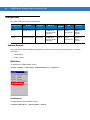
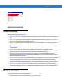

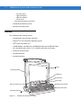

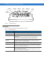
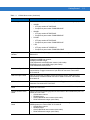
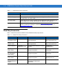
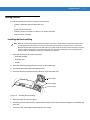

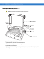
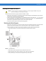

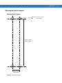
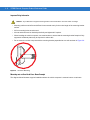
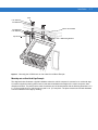
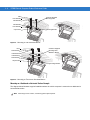
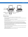

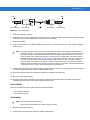

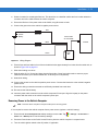

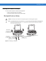
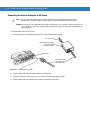
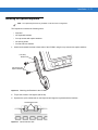
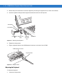
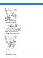
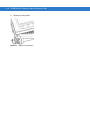
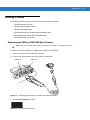
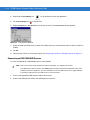
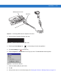
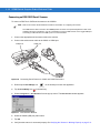
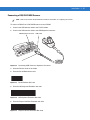
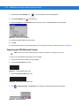
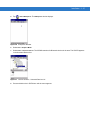
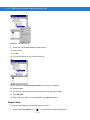
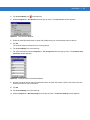
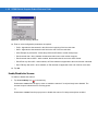
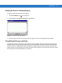
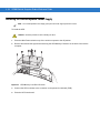

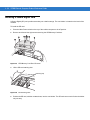
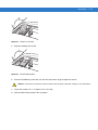
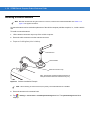
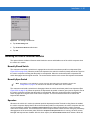
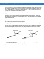
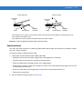

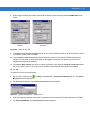
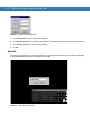
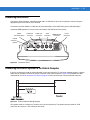

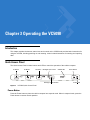
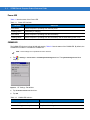
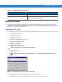
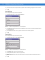
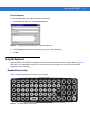
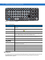
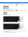

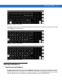
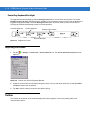
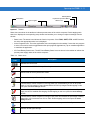
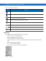

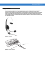
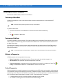

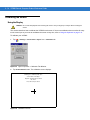

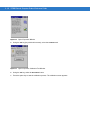
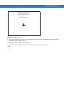
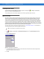

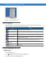
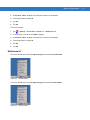
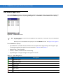
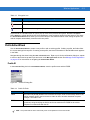

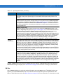
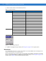
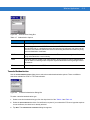

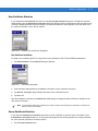
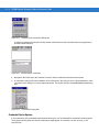
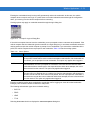
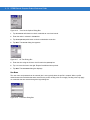
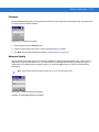
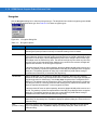
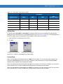
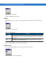
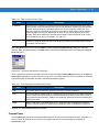
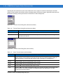
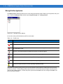
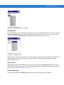
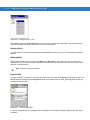
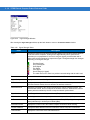
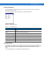
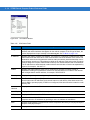
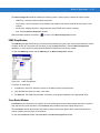
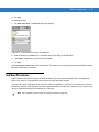
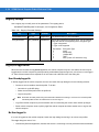
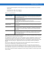

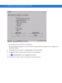

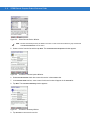
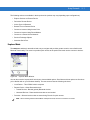
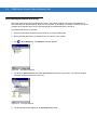
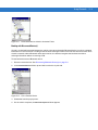
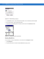
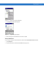
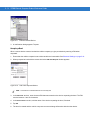
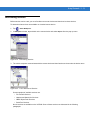
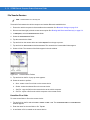
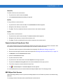
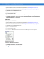
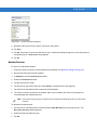

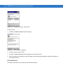
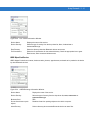
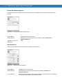
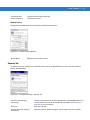
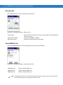


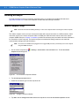
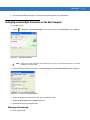
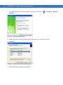
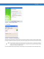


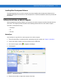
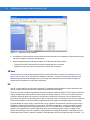


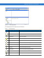
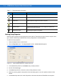
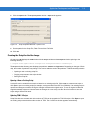

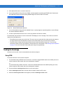
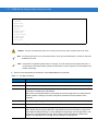
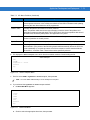
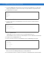
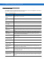

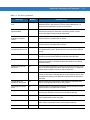
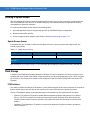
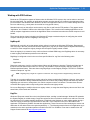
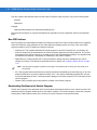

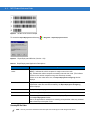
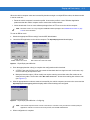
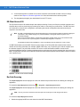
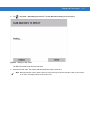

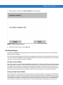
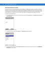
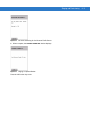
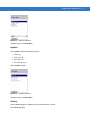
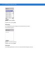
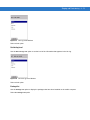


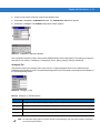
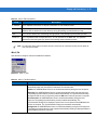
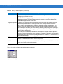

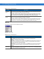


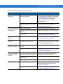
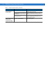
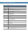
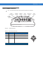
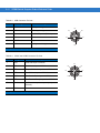
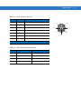


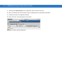
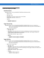
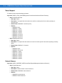
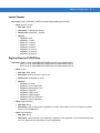
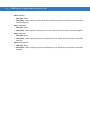
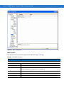
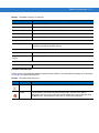
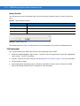


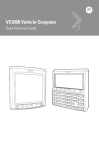

![MC909X User Guide [English] (P/N 72E-72215](http://vs1.manualzilla.com/store/data/006923233_1-b8645820a9c9206bed43f7013f7b5dae-150x150.png)