1
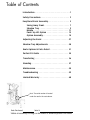
® Owner’s Manual SYMBOL LEGEND ! CAUTION/ATTENTION ENVIRONMENTAL CONDITIONS TYPE BF APPLIED PART DATE OF MANUFACTURE PINCHPOINT SN SEE INSTRUCTIONS FOR USE SERIAL NUMBER Please be environmentally responsible and recycle this product through your recycling facility at its end of life. Afin de préserver l’environnement, veuillez confier ce produit à votre centre de recyclage à la fin de sa durée de vie. Nachdem dieses Produkt ausgedient hat, entsorgen Sie es bitte auf umweltfreundliche Weise, indem Sie es zu der entsprechenden Recyclingstelle bringen. Wees a.u.b. milieubewust en recycleer dit product via uw recycleerder na het verstrijken van de levensduur. Sea responsable con respecto al medio ambiente y recicle este producto al finalizar su vida útil en el lugar de reciclaje correspondiente. Siate responsabili verso l’ambiente e riciclate questo prodotto, al termine della sua vita d’uso, presso la vostra sede di riciclaggio. Kierrätä tämä tuote sen käyttöiän lopussa ympäristövastuullisella tavalla paikallisella kierrätyslaitoksella. Var miljömedveten och återvinn denna produkt efter dess användning. Vi ber deg ta hensyn til miljøet og resyklere dette produktet ved hjelp av de rette resykleringsfasilitetene når produktet ikke lenger kan brukes. Vis venligst hensyn til miljøet ved at levere produktet til det nærmeste genbrugsanlæg, når det ikke længere fungerer. Por favor, assuma responsabilidade ambiental, reciclando este produto em suas instalações de reciclagem no final de sua vida útil. 800.342.8968 www.easystand.com Table of Contents Introduction . . . . . . . . . . . . . . . . . . . . . . . . . . . . . 1 Safety Precautions. . . . . . . . . . . . . . . . . . . . . . . . 2 EasyStand Evolv Assembly. . . . . . . . . . . . . . . . . . 3 Swing-Away Front. . . Shadow Tray . . . . . . . Mobile. . . . . . . . . . . . Pow’r Up Lift Option . Option Assembly. . . . . . . . . . . . . . . . . . . . . . . . . . . . . . . . . . . . . . . . . . . . . . . . . . . . . . . . . . . . . . . . . . . . . . . . . . . . . . . . . . . . . . 7 . . 9 . 11 . 13 . 18 Adjusting the Evolv . . . . . . . . . . . . . . . . . . . . . . 27 Shadow Tray Adjustments . . . . . . . . . . . . . . . . . 30 Evolv Options & Parts Detail . . . . . . . . . . . . . . . 31 Perfect Fit Guide . . . . . . . . . . . . . . . . . . . . . . . . 35 Transferring. . . . . . . . . . . . . . . . . . . . . . . . . . . . 36 Standing. . . . . . . . . . . . . . . . . . . . . . . . . . . . . . . . 37 Maintenance . . . . . . . . . . . . . . . . . . . . . . . . . . . 38 Troubleshooting . . . . . . . . . . . . . . . . . . . . . . . . . 39 Limited Warranty . . . . . . . . . . . . . . . . . . . . . . . . .40 Note: The serial number is located under the seat in the seat column. Date Purchased Serial # Videos on assembly & fitting can be viewed at www.easystand.com/videos Introduction Congratulations on the purchase of an EasyStand standing frame! We at Altimate Medical have designed the EasyStand with comfort and happiness in mind. EasyStand Description The EasyStand line of products is intended for individuals who are able to transfer independently or with assistance from a caregiver and/or lifting device. It is a useful tool for rehabilitation, home, school, and work use. EasyStand standing frames support the user from sitting to the standing position. Various options such as support, choice of manual or Pow’r Up Lift may be added to facilitate individual needs. Indications for Use The EasyStand Evolv line of products is intended to assist individuals who have difficulty rising from a seated position to a standing position and is indicated for individuals weighing up to 200 lbs. (Medium), 280 lbs. (Large), and 350 lbs. (XT). This manual is an integral part of the standing system and s hould be read completely and thoroughly by anyone operating the unit. This will ensure the EasyStand is assembled properly and used in the most beneficial manner. Altimate Medical recommends that an attendant be present when the EasyStand is being used. Should any problem arise that cannot be solved by reading this m anual, please contact a local supplier or call Altimate Medical, Inc., at 800-342-8968 or 507-697-6393. It is necessary to inspect the EasyStand Evolv at least weekly to ensure it is in safe operating condition. EasyStand adjustments that are listed in the product owner’s manual can be made by the operator by following the instructions for use. After an adjustment is made, inspect the EasyStand to ensure all hardware and adjustable components are properly secured per the instructions for use. Replacement of worn parts, major adjustments, or any other important corrections should be handled by an authorized supplier or service center. Only Altimate Medical, Inc., approved replacement parts should be used to ensure safety and performance. Do not use the EasyStand without consulting a physician. Failure to consult a qualified physician prior to using the EasyStand could lead to severe medical problems. We recommend a good standing program be established and supervised by a qualified physician or physical therapist. Join the Standing Community! Our goal is simple - to empower people with disabilities to stand up for their health. Connect, share, and learn from other people with disabilities, special needs parents, clinical professionals, and the experts in standing on one of our social networks. By keeping your standing program “top of mind” you will have the greatest chance of maintaining a standing routine that maximizes all the benefits of standing! Read, share, and comment on the EasyStand Blog at blog.easystand.com Find EasyStand on these social networking sites: page 1 Introduction Safety Precautions • If a user does not meet these specifications and has not been properly fitted by a qualified therapist or physician, Altimate Medical, Inc., does not recommend using the EasyStand. Evolv Medium - is designed to accommodate most individuals from 4’0”-5’6” (122-168 cm) and up to 200 lbs. (90 kg) Evolv Large - is designed to accommodate most individuals from 5’0”-6’2” (152-188 cm) and up to 280 lbs. (127 kg) Evolv XT - is designed to accommodate most individuals from 6’0”-6’10” (183-209 cm) and up to 350 lbs. (159 kg) For more detailed specifications visit our website easystand.com • Altimate Medical, Inc., recommends consulting with a therapist or physician prior to starting a standing program. • Check the EasyStand periodically ensure that all nuts, bolts and adjustable parts are tightened securely. • Never make adjustments to the EasyStand while a user is in the standing position. • Never reposition the foot plates while a user is in the standing position. Consult with a therapist or physician for proper foot placement and angle. • It is necessary to inspect the EasyStand Evolv at least weekly to ensure it is in safe operating condition. Pay particular attention for loose hardware. If the EasyStand is equipped with the optional Pow’r up lift please inspect the electrical cables for any wear and to ensure they are attached properly. Replacement of worn parts, major adjustments, or any other important corrections should be handled by an authorized dealer or service center. Only Altimate Medical, Inc., approved replacement parts should be used to ensure safety and performance. • If the EasyStand is being used in the home environment, please inspect the unit prior to each use to ensure there is no damage or unexpected wear to the EasyStand that may have been caused unintentionally by pets, pests or children. • If the unit was exposed to temperatures of less than 50˚F (10˚C), the unit must warm to room temperature before use. • Operating Conditions: Temperature: 41˚F (5˚C) -104˚F (40˚C), Relative humidity: 20% - 90% at 86˚F (30˚C), Atmospheric Pressure: 700 to 1060hPa. • Storage/Transport Conditions: Temperature: 14˚F (-10˚C) -122˚F (50˚C), Relative humidity: 20% - 90% at 86˚F (30˚C), Atmospheric Pressure: 700 to 1060hPa. • The EasyStand can be used at a maximum altitude of 3,050 meters (10,000 feet). • The expected service life of an EasyStand is considered 5 years under normal use conditions. Note: This may vary based upon use. • Use body weight to lower the seat. Do not use excessive force. • The EasyStand is for indoor use on level surfaces only. • Violently thrusting in the EasyStand may cause it to tip. • Always put the rear casters and/or wheels in the locked position before transferring into the EasyStand. Use these locks to keep the EasyStand stationary. • The EasyStand Evolv meets EN12182:1999 (test standard) for strength, durability and tipping stability. • Please contact Altimate Medical, Inc., for relevant clinical data and literature, strength, durability and test results as applicable. • The EasyStand Evolv Electric Lift meets the requirements of IEC 60601-1 and 60601-2.* • Altimate Medical products are specifically designed to be used with Altimate Medical accessories and options. Unless otherwise noted, accessories and options from other manufacturers have not been tested by Altimate Medical and are not recommended for use with Altimate Medical products. • Product Modifications made without express written consent (including, but not limited to, modification through the use of unauthorized parts or attachments) are not recommended and will void the product warranty. • The wheel lock on the mobile option is to keep the unit in place while transferring or standing stationary and it is not intended to be used as a dynamic brake to stop a rolling mobile unit. ! Caution: This equipment is designed to accommodate a range of users; therefore the unit has various adjustment slots and holes. Avoid placing fingers or other body parts in any of these areas. ! Caution: While in use this equipment has various moving parts, familiarize yourself with the unit and avoid placing hands or fingers near any of these areas. ! Caution: Advise bystanders to keep clear of the unit while in use. ! Caution: Do not use the EasyStand Evolv Mobile option on an incline, it is intended for level surfaces only. Doing so may cause the unit to tip. * Evolv Pow’r Up Lift Option Only page 2 Safety Precautions EasyStand Evolv Assembly ® ® Videos of EasyStand Evolv assembly & fitting can be viewed at www.easystand.com/videos FIG. 3B FIG. 3A FIG. 1 FIG. 2 Seat Assembly FIG. 2B Front Frame page 3 EasyStand Evolv Assembly For Mobile assembly refer to p. 11 If the Evolv XT was ordered, the unit will be fully assembled except for the tray and back option. Refer to p. 18 for the back option assembly, p. 23 for the tray assembly and p. 9 for the Shadow Tray. For any other option assembly, please refer to pp. 18-26. FIG. 2A FIG. 1- Attach the front caster frame to the front frame with bolts and tighten securely. FIG. 2A- Attach the casters to the rear base frame. Tighten securely using the provided wrench. Ensure the casters are flush with the rear base frame. The casters are supplied with a locking compound pre-applied to the threaded stem. Do not remove this material, it is important to prevent the casters from loosening over time. FIG. 2B- Place the front frame and the seat assembly on it’s side, slide the front frame into the opening of the seat assembly as shown. Line up holes and insert all four bolts first, then place nuts onto bolts and tighten securely with hex wrench and 19mm open-ended wrench. Place unit upright on its wheels. If the Swing-Away Front option was ordered, slide the front frame into the opening of the seat assembly as shown on p. 7. To help with installation, place folded cardboard or a block of wood underneath the frame for support. Start all four bolts first, then tighten securely. For more Swing-Away Front assembly, refer to p. 7. FIG. 3A Lift seat up and flip foot plates down. Then insert ratchet handles (located in bag with owner’s manual, E3 model will have ratchet handle already attached) into foot plates. Tighten securely. FIG. 3A- Attach the pump handle to the pump on the seat assembly with bolts and nuts, tighten securely. FIG. 3B- Insert top of handle into pump handle and tighten bolts securely. page 4 EasyStand Evolv Assembly FIG. 5 FIG. 6 FIG. 4 page 5 EasyStand Evolv Assembly FIG. 4 If the Swing-Away Front was ordered, please refer to pp. 7-8. If the Independent Kneepads were ordered refer to p. 25. FIG. 4- Remove ratchet handle and hardware from the knee bracket. Place the bracket and hardware onto the column in the order shown. Ensure the spacer is placed between the two steel brackets. Place the washer and bracket bolt into the bracket assembly and tighten snug, ensuring the knee bracket moves freely. Do NOT overtighten bolt. Place the washer and ratchet handle into the bracket assembly. Tighten ratchet handle once desired position is reached. Spacer Remove the three bolts from the kneepad making sure the plastic insert stays in place. Place the kneepad onto the bracket and insert top two bolts before inserting the middle bolt. Tighten securely. If the independent kneepads were ordered, place pads into knee bracket, the narrow end of the slotted washer for the knee pads will be inserted into the bracket, make sure the larger end of the pad is on the outside of the unit (see drawing on p. 25). FIG. 5 If the Shadow Tray was ordered, please refer to pp. 9-10. FIG. 5- Insert the tray post into the front column with the holes in the post facing upward. The tray clamp on the front frame may need to be adjusted to fit the tray post into the frame. Place tray onto the tray post, insert nut into slot and bolt into hole, tighten securely. If any additional options were ordered, please refer to the drawings on pp. 18-26. FIG. 6- Install the seat onto the seat assembly after all other options are added. For easier installation, pump the seat halfway up. Start all four bolts first, then tighten securely. For Evolv adjustments, see pp. 27-30. Evolv E3 page 6 EasyStand Evolv Assembly Swing-Away Front Assembly Swing-Away Front for Shadow Tray Tray FIG. 8 FIG. 9 Tray Frame FIG. 7 FIG. 8 H-Frame Crossbar Kneepad Bracket FIG. 7 Front Caster Frame page 7 Swing-Away Front Assembly FIG. 7- Insert the H-frame into the front caster frame. Insert pins into the holes provided (crossbar should face seat). If the Front Swivel Casters were ordered refer to p. 24. If the Independent Kneepads were ordered refer to p. 25. FIG. 8- Place the kneepad bracket onto the H-frame. Remove the three bolts from the kneepad making sure the plastic insert stays in place. Place the kneepad onto the bracket and insert the top two bolts before inserting the middle bolt. Tighten securely. FIG. 8 If the Shadow Tray was ordered, skip to p. 9. FIG. 9- Insert the tray frame into the H-frame, tighten knobs securely. Place the tray onto the tray frame, install knobs. Tighten nuts securely. Note: Tray will not move if nuts are overtightened. To use the Swing-Away Front: To swing away the front for transferring, remove pull pins from the bottom of the H-frame. Lift collar and swing away. After positioning client in stander, swing front back into front caster frame and replace pins, making sure the collar is secure. ! Caution: Collar and pins must be securely in place before the user transitions into the standing position. For Evolv adjustments, see p. 27. FIG. 9 Swing-Away Front Assembly page 8 Shadow Tray Assembly ® Shadow Tray Bracket Set-up End Cap Knobs FIG. 10- On the support arm, remove the plastic bag with two mounting bolts and a silver pin. Using a hex wrench, remove the end cap from the Shadow Tray arm. FIG. 13- The knobs on the end of the support arm should be exposed. Rotate the arm down to 90˚. Lock the plunger into place. FIG. 11- Release the plunger by pulling it down, twist to keep it released. FIG. 14- Use a rubber mallet to tap the black cap into the Shadow Tray bracket. Re place the end cap and tighten securely. Shadow Tray Bracket Silver Pin These assembly instructions are shown for the right side mounted Shadow Tray, for the left side mounted Shadow Tray, installation will be on the opposite side. Support Arm FIG. 12- Insert the silver pin into the support arm as shown, while supporting the silver pin, place the support arm into the Shadow Tray bracket until it clicks into place. page 9 Shadow Tray Assembly FIG. 15 FIG. 15- To install the support arm, first remove the nut and the washer from the pre-assembled bolt on the arm, leaving the bolt and the two halves of the fitting (one plastic and one metal) in place on the tube. Thread the bolt into the hip plate, as shown in Fig. 16. Once the bolt has been secured and the support arm has the desired level of tension, install the nut and lock washer on the bolt protruding through the opposite side of the hip plate, closest to the user. Use either the small end of the wrench from the supplied tool kit, or a 17mm socket wrench (preferred) to securely tighten the nut, see p. 30. A setscrew in the metal half of the support arm fitting may be used to adjust the level of the tray once the installation is complete. FIG. 16- Install the tray arm rest to the unit with the two bolts attached. Tighten bolts securely. FIG. 17- Place chest pad onto tray tubes. Place tray onto bracket and insert the bolts into the bracket and tighten securely. For Shadow Tray adjustments, see p. 30. FIG. 17 FIG. 16 FIG. 16 page 10 Shadow Tray Assembly Mobile Assembly FIG. 20 FIG. 18 FIG. 19 Mobile Bracket Knee pad Bracket Mobile Bracket FIG. 22 Mobile Assembly FIG. 21 Wheel Frame page 11 Mobile Assembly FIG. 18 Front Frame FIG. 18- Place the front frame onto the wheel frame. Line up the two bolts with the holes on the wheel frame, start both bolts before tightening securely. Wheel Frame FIG. 21 FIG. 19- Attach the casters to the rear base frame. Tighten securely using the provided wrench. Ensure the casters are flush with the rear base frame. The casters are supplied with a locking compound pre-applied to the threaded stem. Do not remove this material, it is important to prevent the casters from loosening over time. FIG. 20- Place the front frame and the seat assembly on its side, slide the front frame into the opening of the seat assembly as shown. Line up holes and insert all four bolts first, then place nuts onto bolts and tighten securely with hex wrench and 19mm open-ended wrench. Place unit upright. FIG. 21- Place the left-side mobile assembly onto the wheel frame. Line up holes and insert top bolt through the inside as shown. Place the nut onto the bolt and hand tighten. Line up holes and insert bottom bolt through the outside, as shown. Hand tighten the nut onto the bolt, then tighten both bolts securely with a 19mm wrench and hex wrench. Repeat on the opposite side before continuing to the next step. FIG. 22 FIG. 22- Place mobile bracket onto the kneepad bracket. Place kneepad onto the mobile bracket. Insert three bolts into the back of the kneepad. Tighten bolts securely. Remove bolts from mobile bracket. Flip down kneepad and align bracket on mobile assembly. Tighten bolts and nuts securely with 13mm wrench and hex wrench. Repeat steps on the opposite side before continuing to the next step. Lift seat up and flip foot plates down. Then insert ratchet handles into foot plates. Tighten securely. Wheel Locks FIG. 23- The Mobile is equipped with wheel locks for safety while transferring and stability while performing stationary activities. Note the directional arrows imprinted in the center hub of each handrim. To assemble the tray and seat, go to pp. 6, FIG. 5. FIG. 23 page 12 Mobile Assembly Pow’r Up Lift Charging the Battery The EasyStand Evolv Pow’r Up Lift uses two 12 volt sealed lead batteries rated at 2.9 amps each. An EasyStand Evolv can be lifted approximately 100 times on one full battery charge. An audible alarm will sound when the battery is low. Please charge the battery after the alarm sounds. A battery needing to be fully recharged will take approximately 8 hours. FIG. A The EasyStand Evolv can be raised to the standing position while being charged. The function of the charger is to detect a full battery and then provide a constant potential power supply to hold the battery at a full condition without overcharging. When the battery EMF rises to a factory preset point, the charger circuit will not allow the peak output voltage to exceed that value. This factory setting protects a battery from excessive depletion of electrolyte, which can occur from overcharging. The charger can be found in the tool pouch on the back of the unit. ! CAUTION: Use only the Linak charger, model numbers 00CH01-XX OR 10CH01S-00, provided by Altimate Medical with the Pow’r Up option. The hand pendant is a Type BF applied part. 1. Plug the receptacle into a wall outlet. The light on the charger will be green indicating an open circuit. FIG. B 2. FIG. A- Plug the charger cord into the side of the hand control. The light on the charger will turn yellow indicating the batteries are being charged. 3. FIG. B- The unit will arrive unplugged from the battery, plug in the white cord that supplies power to the actuator and the black cord that supplies power to the remote. The black cord has a notch on it to orient the connector properly. Fully charge battery before use. Note: The white cord has a rubber washer on it, which makes it very sticky and sometimes will not get pushed in completely, make sure to push the cord all the way into the battery. 4. When the batteries are charged, the light on the charger will turn green. 5. Fully charge the batteries every three months or less during periods of intermittent or non-use. ! CAUTION: Ensure the cables are attached properly per the instructions for use. Do not allow the cables to drag on the floor or to catch on objects. page 13 Pow’r Up Lift Option Assembly of the Hand Control FIG. C- Assemble the hand control as illustrated in Fig. C. FIG. C ! CAUTION: The Evolv Pow’r Up Option is not designed for continuous use. Duty Cycle 5% Max, 1 min. / 19 min. Raising the Lift - Press the UP (arrow up) button on the hand control to lift the seat. Lowering the Lift - Press the DOWN (arrow down) button on the hand control to lower the seat. Battery Replacement The batteries are enclosed in the control box of the Pow’r Up Lift (the black box where the cords are plugged in). Once the batteries have reached the end of their life and need to be replaced, do not open the control box; please contact Altimate Medical customer service or a medical equipment dealer for information about purchasing a replacement control box. It is recommended that the batteries be replaced every four years. Please contact a local recycling authority for information about disposing old batteries. IP Rating The IP rating is a classification system indicating the protection degree from dust, water and impact for electrical equipment and enclosures. Pow’r Up Lift components are rated at IP21. The definition for IP21 is as follows: First character definition: 2 - Protected against solid foreign objects of 12.5mm diameter and greater. Second character definition: 1 - Protected against vertically falling water drops. Electromagnetic compatibility Pow’r Up Option components have been designed and tested to meet the applicable EMC requirements. Problems with the EasyStand due to inadequate electromagnetic compatibility is unlikely, however, if any unusual (such as intermittent) behavior of the Pow’r Up option and the EasyStand is noticed and it is being used next to possible interfering equipment such as mobile phones, microwaves, or radio broadcast masts, this could be an indication of electromagnetic interference. If such behavior occurs, use the mechanical release to lower the unit to the seated position and move the EasyStand away from the interfering equipment. Please report any instance of possible electromagnetic interference to AMI’s Customer Service Department. page 14 Pow’r Up Lift Option Guidance and Manufacturer’s Declaration - Electromagnetic Emissions The EasyStand Evolv is intended for use in the electromagnetic environment specified below. The customer or the user of the EasyStand Evolv should assure that it is used in such an environment. Compliance Emissions Test RF emissions CISPR 11 Group 1 RF emissions CISPR 11 Class B Harmonic emissions IEC 61000-3-2 Class A Voltage fluctuations/ Flicker emissions IEC 61000-3-3 Complies Electromagnetic Environment - Guidance The EasyStand Evolv uses RF energy only for its internal function. Therefore, its RF emissions are very low and are not likely to cause any interference in nearby electronic equipment. The EasyStand Evolv is suitable for use in all establishments, including domestic establishments and those directly connected to the public low-voltage power supply network that supplies buildings used for domestic purposes. Guidance and Manufacturer’s Declaration - Electromagnetic Immunity The EasyStand Evolv is intended for use in the electromagnetic environment specified below. The customer or the user of the EasyStand Evolv should assure that it is used in such an environment. Immunity Test IEC 60601 Test Level Compliance Level Electrostatic Discharge (ESD) IEC 61000-4-2 ± 6 kV contact ± 8 kV air ± 6 kV contact ± 8 kV air Floors should be wood, concrete, or ceramic tile. If floors are covered with synthetic material, the relative humidity should be at least 30 %. Electrical Fast Transient/Burst IEC 61000-4-4 ± 2 kV for power supply lines ± 1 kV for input/ output lines ± 2 kV for power supply lines ± 1 kV for input/ output lines Mains power quality should be that of a typical commercial or hospital environment. Surge IEC 61000-4-5 ± 1 kV line(s) to line(s) ± 2 kV line(s) to earth ± 1 kV line(s) to line(s) ± 2 kV line(s) to earth Mains power quality should be that of a typical commercial or hospital environment. Voltage dips, short interruptions and voltage variations on power supply input lines IEC 61000-4-11 <5 % UT (>95 % dip in UT) for 0,5 cycle 40 % UT (60 % dip in UT) for 5 cycles 70 % UT (30 % dip in UT) for 25 cycles <5 % UT (>95 % dip in UT) for 5 s <5 % UT (>95 % dip in UT) for 0,5 cycle 40 % UT (60 % dip in UT) for 5 cycles 70 % UT (30 % dip in UT) for 25 cycles <5 % UT (>95 % dip in UT) for 5 s Mains power quality should be that of a typical commercial or hospital environment. If the user of the EasyStand Evolv requires continued operation during power mains interruptions, it is recommended that the EasyStand Evolv be powered from an uninterruptible power supply or a battery. Power frequency (50/60 Hz) magnetic field IEC 61000-4-8 3 A/m 3 A/m Power frequency magnetic fields should be at levels characteristic of a typical location in a typical commercial or hospital environment. Electromagnetic Environment - Guidance NOTE: UT is the a.c. mains voltage prior to application of the test level. page 15 Pow’r Up Lift Option Guidance and Manufacturer’s Declaration - Electromagnetic Immunity The EasyStand Evolv is intended for use in the electromagnetic environment specified below. The customer or the user of the EasyStand Evolv should assure that it is used in such an environment. Immunity Test IEC 60601 Test Level Compliance Level Electromagnetic Environment - Guidance Portable and mobile RF communications equipment should be used no closer to any part of the EasyStand Evolv, including cables, than the recommended separation distance calculated from the equation applicable to the frequency of the transmitter. Recommended separation distance Conducted RF IEC 61000-4-6 3 Vrms 150 kHz to 80 MHz 3 Vrms Radiated RF IEC 61000-4-3 3 V/m 80 MHz to 2.5 GHz 3 V/m d = 1.2 √ P d = 1.2 √ P80 MHz to 800 MHz d = 2.3 √ P800 MHz to 2.5 GHz Where P is the maximum output power rating of the transmitter in watts (W) according to the transmitter manufacturer and d is the recommended separation distance in meters (m). Field strengths from fixed RF transmitters, as determined by an electromagnetic site surveya, should be less than the compliance level in each frequency range.b Interference may occur in the vicinity of equipment marked with the following symbol: NOTE 1: At 80 MHz and 800 MHz, the higher frequency range applies. NOTE 2: These guidelines may not apply in all situations. Electromagnetic propagation is affected by absorption and reflection from structures, objects, and people. a Field strengths from fixed transmitters, such as base stations for radio (cellular/cordless) telephones and land mobile radios, amateur radio, AM and FM radio broadcast and TV broadcast cannot be predicted theoretically with accuracy. To assess the electromagnetic environment due to fixed RF transmitters, an electromagnetic site survey should be considered. If the measured field strength in the location in which the EasyStand Evolv is used exceeds the applicable RF compliance level above, the EasyStand Evolv should be observed to verify normal operation. If abnormal performance is observed, additional measures may be necessary, such as re-orienting or relocating the EasyStand Evolv. b Over the frequency range 150 kHz to 80 MHz, field strengths should be less than 3 V/m. page 16 Pow’r Up Lift Option Recommended separation distances between portable and mobile RF communications equipment and the EasyStand Evolv The EasyStand Evolv is intended for use in an electromagnetic environment in which radiated RF disturbances are controlled. The customer or the user of the EasyStand Evolv can help prevent electromagnetic interference by maintaining a minimum distance between portable and mobile RF communications equipment (transmitters) and the EasyStand Evolv as recommended below, according to the maximum output power of the communications equipment. Rated maximum output power of transmitter W Separation distance according to frequency of transmitter m 150 kHz to 80 MHz d = 1.2 √P 80 MHz to 800 MHz d = 1.2 √P 800 MHz to 2.5 GHz d = 2.3 √P .12 .23 .12 0.01 .38 .73 .38 0.1 1.2 2.3 1.2 1 3.8 7.3 3.8 10 12 23 12 100 For transmitters rated at a maximum output power not listed above, the recommended separation distance d in meters (m) can be estimated using the equation applicable to the frequency of the transmitter, where P is the maximum output power rating of the transmitter in watts (W) according to the transmitter manufacturer. NOTE 1: At 80 MHz and 800 MHz, the higher frequency range applies. NOTE 2: These guidelines may not apply in all situations. Electromagnetic propagation is affected by absorption and reflection from structures, objects, and people. Activating the Mechanical Emergency Release FIG. E All Altimate Medical electric lift products are equipped with a mechanical release to be used in emergency situations. ! CAUTION: Using the emergency mechanical release as the primary means to return to the seated position can cause damage to the unit. Only use the mechanical release in emergency situations. FIG. E- The release allows the user to be lowered to a seated position in the unlikely occurrence of the battery losing charge while the user is in a standing position. The actuator only retracts if the release is pulled and there is weight on the seat. The release is located on the left side of the seat and is signified by a red tag with the word “EMERGENCY”. 1. To activate the emergency mechanical release pull out the quick release pin located on the left side of the seat. 2. Squeeze the handle and if necessary, push down on the seat. page 17 Pow’r Up Lift Option Option Assembly Back Option PNG50062, PNG50066, PNG50067, PNG50068 To assemble the back option, remove the 2 bolts from the back, slide the back assembly into the seat assembly as shown. Tighten securely with bolts provided, then add the swing-away arms. Remove the nut and lock washer from the arm. Place the arm onto the unit keeping the arm assembly together. Place nut and lock washer onto bolt on the inside of the unit. Tighten securely to desired level of tension. Removable Back Option PNG50171, PNG50172, PNG50173, PNG50174 To attach the Removable Back to the unit, slide the back assembly into the seat assembly as shown. Insert hardware into back tubes with tabs facing upward and toward the back. Tighten securely with knobs provided. NOTE: Make sure hardware is placed into back as shown. page 18 Option Assembly Cane Back 16”Wx21”H PNG50492 Cane Back 18”Wx21”H PNG50493 To assemble the cane back option, slide the back assembly into the seat assembly as shown. Tighten securely with bolts provided. Standard Foot Straps PNG30030 Secure Foot Straps PNG30031 Head Support-Short 21”-30”H PNG50240 FIG A Head Support-Tall 25”-34”H PNG50037 FIG B If you ordered the high mount chest vest bracket see p. 21. FIG A- Place head support bracket onto accessories mounting bracket as shown. Insert 4 bolts and nuts and tighten securely. FIG B- Insert the head support onto the unit and tighten securely. page 19 Option Assembly A B C D E Remove the nuts and bolts from the pump handle. Insert the handle onto the pump. Line up holes and insert bolts, place nuts onto bolts. Tighten securely. A Standard Actuator Left Handle PNG50126 B Standard Actuator Right Handle PNG50059 C Adjustable/ Removable Handle Universal Left/Right PNG50328 D T-Style Handle Extension PNG50070 E Quad Grip Handle Extension PNG50044 page 20 Option Assembly High Mount Chest Vest Bracket PNG11212 High Mount Chest Vest Bracket with Head Support PNG11212 If you ordered the high mount chest vest bracket and head support, place the head support bracket and the high mount chest vest bracket on the unit as shown. Insert 4 bolts and nuts and tighten securely. See p. 19 for head support assembly. Airline Buckle Hip Belt PNG30028 Velcro Hip Belt PNG30029 page 21 Option Assembly Large Contoured Chest Pad PNG30000 Remove bolts from chest pad and place onto tray. Tighten bolts securely. Oversized Tray PNG50194 Chest Strap Small-PNG50192 Large-PNG50193 Padded Tray Cover PNG30295 Y-Style Chest Vest Medium-PNG30171 Large-PNG30021 X-Style Chest Vest Medium-PNG30170 Large-PNG30056 page 22 Option Assembly Swing-Away Front Angle Adjustable Tray Black Molded PNG50490 Place tray onto the tray post, insert nut into slot and bolt into hole, tighten securely. Swing-Away Front Angle Adjustable Clear Acrylic Tray PNG50489 Swing-Away Front Angle Adjustable Oversized Clear Acrylic Tray PNG50410 Angle Adjustable Tray Clear Acrylic PNG50366 Angle Adjustable Tray Clear Acrylic for Mobile PNG50327 Angle Adjustable Tray Black Molded PNG50368 NOTE: Raise the Angle Tray by pulling up on the front of the tray and it will lock into position, to lower the tray, angle the tray all the way up and the mechanism will become free to lower the tray. page 23 Option Assembly Front Swivel Casters for Swing-Away Front Evolv Medium/Large-PNG50314 FIG. A FIG. A- Place a block of wood under the unit to raise the caster frame. Place hardware onto the unit as shown- bolt, washer, frame, spacer, caster assembly, washer, then nut. FIG. B- It is important to ensure the brackets are assembled as shown, with the angular portion of the bracket pointing outward and away from each other. Tighten securely. FIG. B Front Swivel Casters Evolv Medium/Large-PNG50314 Evolv XT-PNG50346 page 24 Option Assembly Swing-Away Front Angle Adjustable Tray Black Molded PNG50490 Place tray onto the tray post, insert nut into slot and bolt into hole, tighten securely. Swing-Away Front Angle Adjustable Clear Acrylic Tray PNG50489 Swing-Away Front Angle Adjustable Oversized Clear Acrylic Tray PNG50410 Angle Adjustable Tray Clear Acrylic PNG50366 Angle Adjustable Tray Clear Acrylic for Mobile PNG50327 Angle Adjustable Tray Black Molded PNG50368 NOTE: Raise the Angle Tray by pulling up on the front of the tray and it will lock into position, to lower the tray, angle the tray all the way up and the mechanism will become free to lower the tray. page 23 Option Assembly Front Swivel Casters for Swing-Away Front Evolv Medium/Large-PNG50314 FIG. A FIG. A- Place a block of wood under the unit to raise the caster frame. Place hardware onto the unit as shown- bolt, washer, frame, spacer, caster assembly, washer, then nut. FIG. B- It is important to ensure the brackets are assembled as shown, with the angular portion of the bracket pointing outward and away from each other. Tighten securely. FIG. B Front Swivel Casters Evolv Medium/Large-PNG50314 Evolv XT-PNG50346 page 24 Option Assembly Independent Knee pads PNG50384 Independent Roho® Knee pads PNG50385 Swing-Away Front Independent Knees PNG50425 Slotted Washers Curve Up Remove ratchet handle and hardware from the knee bracket. Place onto the column in the order as shown. Make sure spacer is placed between the two steel brackets. Leave the bolt just loose enough to allow bracket to slide freely. Note the position of the grey brackets, the curve must go up. The narrow end of the slotted washer for the knee pads will be inserted into the bracket. Lateral Supports 8”-16.5”W PNG50224 Lateral Supports 11”-19.5”W PNG50176 Slide each lateral support onto notch and knob on the accessories mounting bracket. Tighten knobs securely. page 25 Option Assembly Roho® Seat Evolv Medium-PNG30183 Evolv Large/XT-PNG30023 Rotating Seat Evolv Medium-PNG50324 Evolv Large/XT-PNG50318 Push the lever under the seat to rotate. Ensure seat is locked into position prior to transferring. Install the seat onto the seat assembly after all the other options are added. Tighten the bolts securely. Hip Supports Medium-PNG50161 Large-PNG50198 Transfer Seat Evolv Medium-PNG30269 Evolv Large/XT-PNG30270 Slide hip supports onto notch and knob under seat. Tighten knob securely. If adding hip supports off-unit, remove plastic plugs from top and bottom of the seat frame. page 26 Option Assembly ® Adjusting the EasyStand Evolv Foot Plates ! Caution: Never reposition the foot plates while a user is in the standing position. FIG. G- Loosen the clamp connecting the foot bracket to the seat post to adjust the foot plate height and plantar/dorsi. Position the height of the foot bracket so the user’s knee is as close to the seat pivot as possible. The femur should be resting on the seat, at a slight downward angle. ® FIG. G FIG. H Tighten the clamp securely. ! Caution: Avoid placing fingers in the adjustment slot. FIG. H- The foot plates can be abducted in 4 different positions (toe out), by removing the bolt underneath the front edge of the foot plate with a hex wrench and lifting up and turning the foot plate. Make sure the foot plate notch is positioned in one of the four slots.* Place the bolt back into the foot plate once the desired position is reached. *Available on the Evolv E3 if ordered with multi-adjustable foot plates. Knee pad FIG. I FIG. I- To adjust the knee pad depth, loosen the ratchet handle and move into position. Tighten ratchet handle when the desired position is reached. Position the knee pad so the user’s knee is centered in the knee pad and only 2 fingers fit between the back of the leg and the seat. page 27 Adjusting The Evolv Hip Supports FIG. J FIG. J- The hip supports are optional and can be removed for transferring. The hip support width can be adjusted by loosening the knobs underneath the seat. Loosen the knob on the side of the unit to adjust the hip support width. Always tighten securely. The hip supports have a number of attachment holes on the back of the pad which will allow for additional positions vertically and horizontally. The pads may also be bolted on at a straight, 90º, 180º, or 270º position. Please check for fit and interference by bringing the unit to the full standing position and back to sitting again without a user seated in the unit, as the pads may not work perfectly in all positions. FIG. K Lateral Supports FIG. K- The lateral supports are optional and can be removed for transferring. The lateral support width can be adjusted by loosening the knobs on the back of the unit. Always tighten securely. The lateral supports have a number of attachment holes on the back of the pad which will allow for additional positions vertically and horizontally. The pads may also be bolted on at a straight, 90º, 180º, or 270º position. Please check for fit and interference by bringing the unit to the full standing position and back to sitting again without a user seated in the unit, as the pads may not work perfectly in all positions. Adjusting the Evolv page 28 Seat Depth/Back Angle FIG. L ! Caution: These adjustments are only to be made while the unit is in the seated position. FIG. L- Loosen the knob on the seat tube located under the seat. Do not unscrew seat depth knob all the way when adjusting the seat. Depress the spring button and position the back so that the hip pivot is located as close as possible to the user’s hips. Tighten the seat depth knob securely. FIG. M Note: Adjust back angle after each seat depth position change. FIG. M- To adjust the back angle, use the knob located on the following arm. Before standing, the back angle must be set so the indicator on the side of the unit is in the green. FIG. N- The back/seat angle locator is located on the side of the unit. When the unit is in the seated position, the green area indicates the back angle. Before standing, the indicator must be in the green. Green Area FIG. N ! Caution: Before standing, the seat/back angle indicator must be in the green. Failure to set the back angle in green prior to standing could cause the unit to lock in a standing position, causing damage to the unit. Tray/Front Pad FIG. O- To adjust the height of the tray/front pad, loosen the clamp located just above the front column. Lift the tray to the user’s desired height level and tighten the clamp. FIG. O To adjust the depth of the tray/front pad, loosen the clamp located just below the tray. Move the front pad to the user’s desired position and tighten the clamp. ! Caution: While lowering the tray height, keep hands clear of the area underneath the tray. page 29 Adjusting the Evolv Shadow Tray Adjustments ® Tray Depth Adjustment Chest Pad Height Adjustment FIG. B Support Arm Locking Mechanism FIG. A Set Screw FIG. A- To adjust chest pad height, loosen knob and move to desired position. Tighten securely. FIG. B- To adjust the depth of the front pad and tray, loosen the knob located below the tray. Move the front pad to the user’s desired position and tighten the knob. To flip the tray up, pull out and twist the locking mechanism and lift. To adjust the level of the support arm use the set screw to set to the desired position. ! Caution: After flipping the tray up, be certain to put the locking mechanism back into place. Failure to do so can cause the tray to fall suddenly. ! Caution: Avoid placing fingers near the tray tubes and chest height adjustment slots. Shadow Adjustments page 30 Evolv Options & Parts Detail (front) ® page 31 Evolv Options & Parts Detail page 32 Evolv Options & Parts Detail Evolv Options & Parts Detail (rear) ® page 33 Evolv Options & Parts Detail page 34 Evolv Options & Parts Detail Perfect Fit Guide (A) (B) (C) (D) (E) (F) (G) (H) (I) (J) step one - measure Before transferring into the Evolv, measure for approximate (A) seat depth and seat to (B) foot plate settings. step two - seat depth Use the above measurement (A) to adjust the seat depth on the stander, measure from the front of the seat to the back. To adjust the seat depth, loosen the knob under the seat (C). Depress the snap button on the adjustment tube while moving the back (D). Adjust the seat depth until the proper measurement has been reached. Tighten the knob (C) after adjusting. step three - back angle After achieving the desired seat depth, rotate the back angle (E) adjustment knob so the (F) seat/back angle indicator is in the green area prior to standing. Note: Repeat steps 2 and 3 for each color adjustment. step four - foot plates Use the (B) measurement to adjust the foot plate height. Loosen the (G) ratchet handles on the foot plates to adjust height and lantar/dorsi. Tighten ratchet handles after positioning. The knees should be slightly lower than the hip (H). step five - positioning Position the user’s hips as close as possible to (I) Evolv’s hip pivot. To determine correct positioning, only two fingers should fit between the front of the seat and the back of the knee (J). step six - knee pad Adjust the (K) knee pad so it fits comfortably up to the knees. ! Caution: These adjustments are only to be made (K) while the unit is unoccupied and in the seated position. Inspect your standing frame periodically to ensure it is in safe operating condition. page 35 Perfect Fit Guide Transferring For certain individuals, transferring can be a difficult task, especially at first. Like many things, transferring gets easier with practice. With assisted transfers, it is always a good idea to review the transfer strategy with the client before transferring, and talk them through the steps as they are happening. This will help reduce anxiety for the person being transferred. There are many different methods of transferring into the EasyStand Evolv, whether the transfer is independent or with assistance. There are also a variety of options that can be added to the Evolv to help make transferring more manageable. For proper transfer techniques, please seek professional advice from a therapist or physician. ! Caution: Always lock wheel locks on a wheelchair and the casters on the EasyStand Evolv before transferring. Transfer Methods Independent Transfer: For those individuals who are able to transfer independently, Altimate Medical has designed the Evolv base so a wheelchair can be positioned at any angle from parallel to 90 degrees against the edge of the Evolv seat (the front wheelchair caster can even come underneath the front corner of the seat). The kneepads flip up and out of the way to give the person room to bring their legs in and position their feet. The kneepad does not lock in the upright position when transferring, do not grab the kneepad for support. When transferring out of the EasyStand, pump the seat up so it is equal to or higher than the seat the user is transferring into. Stand Pivot Transfer: A caregiver can assist a patient into the stander using a stand pivot transfer. The caregiver helping with the stand pivot transfer assists the person out of their wheelchair to standing, then turns or pivots and sits the person down on the seat of the stander. Patient Lift Transfer: Caregivers can assist people who have a higher level of disability by using a patient lift device, or an overhead ceiling lift to transfer into the EasyStand. The rear legs of the EasyStand Evolv are designed to allow room for the lifting device to be used from many different angles. To make the transfer from a patient lift device, recline the back of the standing frame slightly. With some patient lift devices it may make the transfer easier to lift the Evolv foot plates up to a higher position, allowing the transfer device to slide closer to the base of the Evolv. Be sure to reposition the foot plates and back prior to standing. page 36 Transferring Standing Contraindications Standing/weight bearing may not be an option for the following reasons: If the user has severe contractures or range of motion issues If the user has severe osteoporosis or brittle bone disease If the user has postural orthostatic hypotension If the user has dislocated joints ! Caution: Consumers considering a standing program should consult with a qualified physician and medical team to determine what indications or contraindications exist. Clinicians must use best clinical judgment to evaluate the user’s needs. Implementing a standing program must be determined on an individual basis by the user’s team (Physician, Physical or Occupational Therapist, Rehab Technology Professional/Supplier and the consumer). Consider all indications and contraindications for each client individually to determine if standing/weight bearing is appropriate for them. To Stand ! Caution: Always consult with a physician or therapist before starting a standing program. ! Caution: Before standing, the seat/back angle indicator must be in green. Failure to set the back angle in green prior to standing could cause the unit to lock in a standing position, causing damage to the unit. Do not use the seat angle dial indicator as a reference while in the standing position. It is only to be used as a guide while adjusting the seat depth and back angle in the seated position. Position feet, the knee support, and secure any straps or side supports. Push the pump handle forward with 15-25 long strokes. The seat will slowly rise to the standing position. Remember the seat can be stopped anywhere between sitting and standing. ! Caution: Never make adjustments to the EasyStand while a user is in the standing position. Return to the Seated Position Move and hold the pump handle toward the rear until the desired position is reached. The seat will slowly lower until the handle is released. If difficulty lowering the seat occurs,apply less or more pressure to the handle. If the unit is in the standing position and unoccupied, apply moderate pressure to the seat of the unit while holding the pump handle back. Do not use excessive force. ! Caution: When lowering the unit from standing to sitting, keep all hands and feet clear of the mechanism beneath the seat. page 37 Standing Maintenance Cleaning/Disinfecting • • • • • • • • • • Clean the EasyStand Evolv with a mild, non-abrasive disinfectant or soap and water. Check the EasyStand at least weekly to ensure all nuts, bolts and adjustable parts are tightened securely, failure to do so may result in parts falling off which may cause a choking hazard for children. Do not use bleach or any other bleach-based cleaners on the EasyStand. Disinfecting wipes are safe to use on metal and non-porous surfaces. Use a damp sponge with mild soap or a mild, non-abrasive disinfectant. Spot clean Neoprene with mild soap and water. Neoprene covers may be removed and hand washed with water. Air dry the covers. Always use care when removing and replacing the covers. Do not dry clean any upholstery items. If the EasyStand is being used with one user, clean the EasyStand on a monthly basis or as needed If the EasyStand is being used in a multiple user environment, the EasyStand should be cleaned after each use. Urethane Coated Fabrics (Dartex or generic equivalent) • The recommended cleaning and disinfection instructions should be followed whenever possible to avoid damage to the PU membrane which could lead to premature failure of the cover. • For superficial dirt, use a disposable wipe and a warm solution of neutral detergent. Do not use abrasive cleaners. • Disinfect using a 0.1% sodium hypochlorite solution (1000ppmm chlorine), stronger bleach solutions not recommended. • Thoroughly rinse any remaining cleaning solution with water and dry fabric before re-use or storage. • Do not iron. Hydraulic Actuator Maintenance • An initial break-in period of approximately 50-100 full cycles is normal for the hydraulic unit. The very close fit of its mating parts gives each pump its own break-in “feel” and signature sound, signaled by a squeaking or a less-than-smooth stroke. • If the pump is leaking oil, call your local EasyStand Supplier for a replacement. The serial number on the EasyStand will be needed. • Do not exert excessive force on the pump handle or use the pump handle to move an EasyStand. This may cause damage to the pump handle and/or the pump mechanism and will void any warranty. • User maintenance is not required or recommended on the hydraulic pump. Never apply lubricant, household oil, grease, or a similar product to any part of the unit. Some compounds may react with the seals used in the manufacture of this product. This may damage the unit and will void any warranty. • Do not exceed the rated weight limit. • If the EasyStand was shipped and exposed to a temperature of less than 50 degrees Fahrenheit, the hydraulic unit must warm to room temperature before use. Failure to follow this step could damage the unit and render it inoperable. • Once the standing position is reached, the pump may settle back one stroke, this is normal. • It is not always necessary to push the pump handle all the way back to lower the seat. Trypushing the handle back in different positions if it is difficult to lower the seat. • If the unit is in the standing position and unoccupied, it is necessary to apply pressure to the seat of the unit while pushing the pump handle back. Purging The Hydraulic Actuator The hydraulic pump on the EasyStand has a high probability of getting air trapped in the internal workings of the unit. This is usually caused by in-transit handling and is quite normal. Please follow the simple steps below, as manual hydraulic systems may never operate properly unless the entrapped air is correctly purged. The unit must be at room temperature for this procedure. 1. Pump the handle until the full extension is reached. 2. Now continue pumping the handle slowly for an additional 10 strokes. This will properly purge the system. Maintenance page 38 Troubleshooting My EasyStand will not go into the full standing position: As of June 2011 the EasyStand (manual hydraulic pump only) is equipped with a safety feature to prevent over travel of the lifting/following arm mechanism in the event the back angle is improperly adjusted to exceed the recommended angle. The unit will not reach full standing unless the back angle is adjusted within the green range at the seated position. Refer to p. 29 for proper instructions. My EasyStand will not release properly from the standing to the seated position: • Try pushing the handle back into different positions; do not push the pump handle back hard into one position. • Weight on the seat is needed for the unit to descend properly; if the unit is unoccupied or the user is leaning forward and not enough weight is distributed on the seat, apply pressure by hand to the back of the seat while pushing back on the pump handle. • Ensure the back angle is adjusted properly, if the back angle is too far forward or back the unit may not descend properly. Adjust the back angle toward 90 degrees so it will release properly. My hydraulic does not work smoothly, it is not leaking oil but acting inconsistent: With the unit unoccupied, pump it all the way to standing. Once the seat is in the standing position, pump 12 to 15 additional strokes to bleed any air out and circulate fluid. Pull back on the pump handle to return the seat to a seated position, one may apply pressure with a hand to the back of the seat while pushing back on the pump handle. In most cases purging the hydraulic pump will eliminate inconsistent operation. My lower leg length is too short for the stander: Evolv Large: Replace large foot brackets with medium foot brackets. My Evolv seat won’t go all the way down to the seated position: Look closely at the four main frame bolts that attach the front end to back end. Most commonly the kidney shaped pump mount brackets are not secured correctly. They are positioned above the frame bolts with an exposed hole where the bolts should go through. This angles/raises the pump and won’t allow the unit to go to the complete seated position. Remove main bolts and make sure they go through both the front frame, the back frame and the pump mount brackets. Evolv Pow’r Up Lift: Make sure the cords are fully seated in the battery box. The grommet ring on the cords make it a very tight fit. Unplug the cords and plug them back in, pushing hard. Evolv with Swing-Away: Remove quick pin and simply lift the collar on the opposite side past the frame and swing out. Shadow Tray is not level: If Shadow Tray is leaning forward or back, adjust the back angle. If the tray is leaning from right to left, adjust the set screw on the support arm to level the support arm. How to use the rotating seat: Push up on the lever under the seat and rotate the seat right or left 90° or until it locks into position. Transfer to seat and push up on the lever to unlock and rotate to a forward position. How can I tell if I have an Evolv Medium or Large: Measure the seat. Front to Back: Large is 22”; Medium is 18” How do I order parts: Contact a local supplier and have the serial number ready. If the local supplier is unknown, call Altimate Medical Customer Service, (800) 342-8968, and have the serial number ready. page 39 Troubleshooting Limited Warranty This warranty is extended only to the original purchaser/customer (or supplier non consumer who does not buy or resell). Altimate Medical, Inc., warrants the EasyStand Evolv against defects in materials and workmanship as listed below. • Steel Frames - 5 year warranty • Hydraulic Actuator - 2 year warranty • Upholstered components, plastic pads, rubber parts, painted surfaces, bearings and other parts not specifically identified above - 90 day warranty Warranty on Electric lift option components is as follows: • Actuator & Hand Pendant – 2 year warranty • Control Box & Battery – 90 days • Battery Charger – 90 days The warranty period commences for the consumer on the purchase date from the seller/supplier. If the product is rented or otherwise not sold to a consumer, the warranty period commences from the date of invoice from Altimate Medical. Any product proven to Altimate Medical satisfaction to be defective and within warranty period, shall be repaired or replaced at Altimate Medical’s option. ALTIMATE MEDICAL SOLE OBLIGATION AND YOUR EXCLUSIVE REMEDY UNDER THIS WARRANTY SHALL BE LIMITED TO SUCH REPAIR AND/OR REPLACEMENT. This warranty does not include any labor charges incurred in replacement parts installation. Freight charges to factory are at the expense of consumer to seller. Return freight charges will be prepaid by Altimate Medical. For warranty service, please contact the authorized supplier from whom you purchased your Altimate Medical product. In the event you do not receive satisfactory warranty service, please write directly to Altimate Medical at the address below. Do not return products to our factory without prior authorization. LIMITATIONS AND EXCLUSIONS: The foregoing warranty shall not apply to serial numbered products if the serial number has been removed or defaced. Products subject to negligence, abuse, misuse, improper operation, improper maintenance, improper storage, or damages beyond Altimate Medical’s control are not covered by this warranty, and that evaluation will be solely determined by Altimate Medical. Products modified without Altimate Medical’s express written consent (including, but not limited to, modification through the use of unauthorized parts or attachments) are not covered by this warranty. The warranty shall not apply to problems arising from normal wear or failure to follow instructions. The warranty will be void if parts not manufactured by Altimate Medical or parts not complying with original equipment specifications are added to an Altimate Medical product. THE FOREGOING WARRANTY IS EXCLUSIVE AND IN LIEU OF ALL OTHER EXPRESS WARRANTIES. ALTIMATE MEDICAL SHALL NOT BE LIABLE FOR ANY CONSEQUENTIAL OR INCIDENTAL DAMAGES WHATSOEVER. Altimate Medical maintains a policy of continual product improvement and reserves the right to change features, specifications, and prices without prior notification. Check with Altimate Medical for latest information. Altimate Medical, Inc., 262 W. 1st St., Morton, MN 56270 USA Phone: 507•697•6393 Fax: 507•697•6900 800•342•8968 www.easystand.com [email protected] Environmental Issues After life of the product: • Recycle in accordance with the recycling codes of your country. • Recycle all metal parts. • Plastic parts should be disposed of or recycled according to the directive in your country. • Please inquire at your local disposal management and recycling center for local codes. • Return hydraulic actuator or damping cylinder (Pow’r Up only) to Altimate Medical, Inc. Warranty page 40 262 West 1st St. Morton, MN 56270 USA Toll Free: 800.342.8968 or 507.697.6393 Fax Free: 877.342.8968 or 507.697.6900 email: [email protected] www.easystand.com Standing technology should only be used under the guidance of a physician with recommendations for standing program protocol and any medical precautions. Standing programs should be monitored by the attending therapist. Altimate Medical maintains a policy of continual product improvement and reserves the right to change features, specifications, and prices without prior notification. Check with Altimate Medical for latest information. FORM MANAEVM 123114 REV A Copyright © 2014 Altimate Medical, Inc. All rights reserved. Printed in the U.S.A.