1
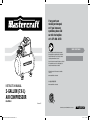
If any parts are
missing or damaged,
or if you have any
questions, please call
our toll-free helpline
at 1-877-888 -3872.
Quick Start Guide
Read and understand this instruction manual
thoroughly before using the product. It contains
important information for your safety as well as
operating and maintenance advice.
Keep this instruction manual for future use. Should
this product be passed on to a third party, this
instruction manual must be included.
An English version of this manual is available
online at:
www.canadiantire.ca/manuals
中文版說明書請參照:
www.canadiantire.ca/manuals
INSTRUCTION MANUAL
2-GALLON (7.6 L)
AIR COMPRESSOR
058-7000-2
Version: 01
218549
2-GALLON (7.6 L) AIR COMPRESSOR - 058-7000-2
058-7000-2-Air-Compressor-2G-EN-03.indd 1-2
6/11/12 8:14 AM
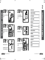
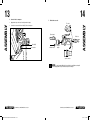
0 (0ff)
Set the power switch to the 0 (off)
position.
STEP 2
Close the tank drain valve,
located on the bottom of the air
tank.
CLOSE
Turn the air pressure regulator
knob counter-clockwise until
it stops.
SAFETY GUIDELINES
CLOSE
Set the power switch to the I (on)
position.
NOTE: For details, refer to the
accessories diagram on page 14.
2-GALLON (7.6 L) AIR COMPRESSOR - 058-7000-2
OPEN
3
4–6
KEY PARTS DIAGRAM
7
KEY PARTS LIST
8
INTENDED USE
STEP 5
STEP 6
Attach hose and accessories.
058-7000-2-Air-Compressor-2G-EN-03.indd 3-2
TECHNICAL SPECIFICATIONS
Plug in the power cord.
STEP 3
Apply plumber's tape on all the
threads to prevent air leakage.
STEP 4
QUICK START GUIDE
9 – 10
ASSEMBLY
11 – 14
OPERATING INSTRUCTIONS
15 – 16
MAINTENANCE
17 – 18
TROUBLESHOOTING
19 – 20
EXPLODED VIEW
21
PARTS LIST
22
WARRANTY
23 – 24
TABLE OF CONTENTS
QUICK START GUIDE
STEP 1
2
Turn the air pressure regulator
knob clockwise until desired
pressure is reached.
2-GALLON (7.6 L) AIR COMPRESSOR - 058-7000-2
6/11/12 8:14 AM
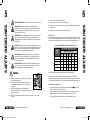
PRODUCT NUMBER
058-7000-2
PEAK HORSEPOWER
1/3
TANK SIZE
2 U.S. GALLONS (7.6L)
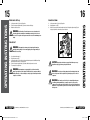
This manual contains information that relates to PROTECTING
PERSONAL SAFETY and PREVENTING EQUIPMENT PROBLEMS. It
is very important to read this manual carefully and understand
it thoroughly before using the product. The symbols listed
below are used to indicate this information.
AIR DELIVERY (SCFM*) @ 40 PSI 1.0
DANGER! Potential hazard that will result in serious injury or loss of life.
AIR DELIVERY (SCFM*) @ 90 PSI 0.7
CUT-IN PRESSURE (PSI)
85
CUT-OUT PRESSURE (PSI)
100
FUSE
3 A, 5 x 20 mm
POWER
120 V, 60 Hz, 2.6 A
WEIGHT
16 lb (7.3kg)
POWER CORD
STJ 18 AWG / 6' (1.82m)
EXTENSION CORD
SJT 16 AWG / MAXIMUM 50’ (15m)
* SCFM: Standard Cubic Feet per Minute The volumetric flow rate of a gas (=
corrected to standardized conditions of temperature and pressure.)
2-GALLON (7.6 L) AIR COMPRESSOR - 058-7000-2
058-7000-2-Air-Compressor-2G-EN-03.indd 3-4
WARNING! Potential hazard that could result in serious injury or loss of life.
CAUTION! Potential hazard that may result in moderate injury or damage to equipment.
IMPORTANT! Installation, operation or maintenance information that is important but
not hazard related.
Safety Advice
DANGER!
1.
4
SAFETY GUIDELINES
TECHNICAL SPECIFICATIONS
3
RISK OF FIRE OR EXPLOSION. Do not spray a flammable or combustible liquid or
paint near sparks, flames, pilot lights or in a confined area. The spray area must be
well-ventilated. Keep compressor at least 20’ (6 m) away from spray area. Do not
carry and operate the compressor or any other electrical device near the spray area. Never smoke
when spraying. Use a minimum of 25’ (7.6 m) of hose to connect a spray gun to the compressor.
2.
RISK OF ELECTRIC SHOCK. Do not expose to rain. Store indoors. Hazardous voltage.
Disconnect from power source before servicing. Compressor must be grounded. Do
not use grounding adaptors.
3.
RISK OF BURSTING. Make sure the regulator is adjusted so that the compressor outlet
pressure is set lower than the maximum operating pressure of the spray gun or tool.
Before starting the compressor, pull the ring on the safety valve to make sure the valve
moves freely (see diagram on page 18). Drain water from tank after each use. Do not
weld or repair tank.
2-GALLON (7.6 L) AIR COMPRESSOR- 058-7000-2
6/11/12 8:14 AM
5
6
RISK OF PERSONAL INJURY. Never spray compressed air or material at self or others.
5.
RISK OF BURSTING. Check the maximum pressure rating in the manual or
identification label. The compressor outlet pressure must be regulated so that it does
not exceed the maximum pressure rating. Relieve all pressure in the hose before
removing or attaching accessories.
6.
RISK OF BURSTING. Do not adjust the pressure switch or safety valve for any reason.
They have been preset at the factory for this compressor’s maximum pressure.
Tampering with the pressure switch or the safety valve may cause personal injury or
property damage.
7.
RISK OF BURNS. The pump and the manifold generate high temperatures. In order to
avoid burns or other injuries, do not touch the pump, the manifold or the transfer tube
while the compressor is running. Allow the parts to cool down before handling or
servicing. Keep children away from the compressor at all times.
8.
9.
6. Do not operate the compressor if it is not in a stable position.
7. Do not operate the compressor on a rooftop or an elevated position that could allow the unit to fall
or be tipped over.
8. Always replace a damaged gauge before operating the unit again.
Extension cords
As the distance from the supply outlet increases, you must use a heavier gauge extension cord. Using
extension cords with inadequately sized wire causes a serious drip in voltage, resulting in loss of power
and possible product damage. Refer to the table here to determine the required minimum wire size.
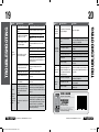
Recommended Minimum Wire Gauge for Extension Cords* (120 V)
RISK TO BREATHING. Be certain to read all labels when you are spraying paints or
toxic materials, and follow all safety instructions. Use a respirator mask if there is a
chance of inhaling anything you are spraying. Also, NEVER directly inhale the air
produced by a compressor.
RISK OF EYE INJURY. Wear ANSI Z87.1 approved safety goggles when using an air
compressor. Do not point any nozzle or sprayer toward a person or any part of the
body. Serious injury may occur if the spray penetrates the skin.
WARNING!
CORD SIZE IN AWG (AMERICAN WIRE GAUGE)
AMPERE
RATING
Extension cord length in feet
25'
50'
75'
100'
150'
200'
0-5
16
16
16
14
12
12
5.1- 8
16
16
14
12
10
--
8.1 - 12
14
14
12
10
--
--
12.1 - 15
12
12
10
10
--
--
15.1 - 20
10
10
10
--
--
--
* Based on limiting the line voltage drop to five volts at 150% of the rated amperes.
1. Pull the pressure safety valve ring every day in order to ensure that
the valve is functioning properly.
The smaller the gauge number of the wire, the greater the capacity of the cord. For example, a
14-gauge cord can carry a higher current than a 16-gauge cord. When using more than one extension
cord to make up the total length, be sure each cord contains at least the minimum wire size required.
2. The compressor must be located in a well-ventilated area for
cooling, and must be a minimum of 12” (31 cm) away from the
nearest wall.
Guidelines for using extension cords
3. Protect the air hose and the power cord from damage and
puncture. Inspect them for weak or worn spots every week, and
replace them if necessary.
•
If you are using an extension cord outdoors, be sure it is marked with the
Canada) to indicate it is acceptable for outdoor use.
•
4. Always wear hearing protection when using an air compressor. Failure to do so may result in
hearing loss.
Ensure your extension cord is properly wired and in good electrical condition. Always replace a
damaged extension cord or have it repaired by a qualified technician before using it.
•
Protect your extension cords from sharp objects, excess heat and damp or wet areas.
2-GALLON (7.6 L) AIR COMPRESSOR - 058-7000-2
058-7000-2-Air-Compressor-2G-EN-03.indd 5-6
SAFETY GUIDELINES
SAFETY GUIDELINES
5. Do not carry the compressor while it is running.
4.
"W-A" ("W" in
2-GALLON (7.6 L) AIR COMPRESSOR - 058-7000-2
6/11/12 8:14 AM
7
8
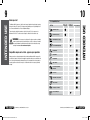
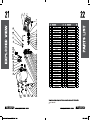
A. ELECTRIC MOTOR: The motor is used to power the pump.
OUTLET PRESSURE
GAUGE (I)
ELECTRIC MOTOR (A)
TANK PRESSURE
GAUGE (H)
POWER SWITCH (C)
C. POWER SWITCH: This switch turns the compressor on and off. It is operated manually and when it
is in the ON position, it allows the motor to start if the pressure in the air tank is below the factory
set cut-in pressure, and allows the motor to stop if the pressure in the air tank reaches the factory
set cut-out pressure. Be sure to set this switch to the OFF position when the compressor is not
being used and before unplugging the compressor.
D. AIR TANK: The tank is where the compressed air is stored.
E.
AIR OUTLET (K)
AIR TANK (D)
AIR PRESSURE
REGULATOR (G)
POWER CORD: This compressor should be
used on a nominal 120 V grounded circuit.
Use a power cord that is equipped with a
grounding plug. Verify that the compressor
is plugged into an outlet that has the same
configuration as the plug. Do not use an
adapter with this compressor.
Plug
Grounded
outlets
Grounding pin
F.
SAFETY
VALVE (F)
SAFETY VALVE: This valve is used to prevent system failure by draining pressure from the system
when it reaches a preset level if the pressure switch has not shut down the motor. It will pop open
automatically, or it can be activated manually by pulling the ring on the valve.
KEY PARTS LIST
KEY PARTS DIAGRAM
B. FUSE: The fuse is used to protect the motor.
G. AIR PRESSURE REGULATOR: The regulator is used to adjust the pressure inside the line to the
tool that is being used. Turn the knob clockwise to increase the pressure and counter-clockwise to
decrease the pressure.
POWER CORD (E)
[
WARNING! Do not exceed the tool’s maximum working pressure.
H. TANK PRESSURE GAUGE: The gauge measures the pressure level of the air that is stored in the
tank. It cannot be adjusted by the operator and it does not indicate the pressure inside the line.
I.
OUTLET PRESSURE GAUGE: The gauge measures the regulated outlet pressure.
J.
AIR TANK DRAIN VALVE: The drain valve is used to remove moisture from the air tank after the
compressor is shut off.
WARNING! Do not attempt to open the drain valve when there is more than
10 PSI of air pressure in the tank.
K. AIR OUTLET: The outlet is connected to the 1/4” (6.4 mm) NPT air hose.
2-GALLON (7.6 L) AIR COMPRESSOR - 058-7000-2
058-7000-2-Air-Compressor-2G-EN-03.indd 7-8
2-GALLON (7.6 L) AIR COMPRESSOR - 058-7000-2
6/11/12 8:14 AM
Before you start
This Mastercraft® Air Compressor is ideal for a wide-range of applications from fastening to greasing
and engine cleaning. The 2-gallon (7.6 L) design provides optimum pressure. It is light weight and oilfree. It comes standard with a recoil hose and attachment fittings.
The procedures described in this manual are solely for this 2-gallon (7.6 L) air compressor at a
maximum of P=100 PSI. The device has been designed / constructed for household use only.
WARNING! This air compressor is not designed for continuous operation or unlimited,
commercial operations and may be used in dry areas only. This air compressor is intended
to be used in maximum 30-minute intervals and should rest for 30 minutes before being
used again. Do not exceed the maximum working time.
10
Tool Compatibility Chart
Operates Tool
Continuously
Air Tool
Operates Tool
Intermittently
Inflation/Recreation
Brad Nailer (18-gauge)
Finishing Nailer (16-gauge)
3-in-1 Brad/Finishing/Stapler
Framing Nailer
Compatible compressor & air tool - proper usage & operation
Always ensure the use of appropriately matched air tools with your Mastercraft® Air Compressor. Be
sure that the air compressor being used can supply the appropriate volume, pressure and delivery rate
of air to the tool(s) without running continuously. Using tools or combinations of tools that, together or
separately, require more than the air compressor can deliver will void the air compressor guarantee/
warranty.
Roofing Nailer
Flooring Nailer
Not Recommended
INTENDED USE
INTENDED USE
9
Impact Wrench
Die Grinder, Angle Grinder,
Air Ratchet
Cut-off Tool
Drill, Hammer, Chisel, Shears
Sander, Polisher
Paint Sprayer, 20–45 PSI
Grease/Caulking Gun
2-GALLON (7.6 L) AIR COMPRESSOR - 058-7000-2
058-7000-2-Air-Compressor-2G-EN-03.indd 9-10
2-GALLON (7.6 L) AIR COMPRESSOR - 058-7000-2
6/11/12 8:14 AM
11
12
Unpack the air compressor. Inspect the unit for damage. If the unit has been damaged, contact the
retailer immediately.
IMPORTANT! If any parts are missing or damaged, or if you have any questions,
please call our toll-free helpline at 1-877-888-3872.
THE CARTON SHOULD CONTAIN:
• Air compressor
• Owner’s manual
ACCESSORY
QTY
11/16” open-end wrench or
1
Adjustable wrench
1
Cross-headed screwdriver
1
2.
Check the air compressor’s identification label to ensure that you have purchased the intended
model and that it has the required pressure rating for its intended use.
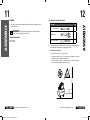
3.
Positioning of the air compressor:
a.
Position the air compressor near an electrical outlet.
b.
The compressor must be at least 12” (31 cm) from any wall or obstruction, in a clean, wellventilated area to ensure sufficient air flow and cooling.
c.
Place the air compressor on the floor or a hard, level surface. The air compressor must be
level to ensure proper drainage of the moisture in the tank.
ASSEMBLY
1.
TOOLS REQUIRED FOR ASSEMBLY (NOT INCLUDED):
ASSEMBLY
ASSEMBLY
Assembly
Wall
> 12" /
31 cm
2-GALLON (7.6 L) AIR COMPRESSOR - 058-7000-2
058-7000-2-Air-Compressor-2G-EN-03.indd 11-12
2-GALLON (7.6 L) AIR COMPRESSOR - 058-7000-2
6/11/12 8:14 AM
14
4.
Connect air hose to compressor
•
Apply plumber's tape on the hose threads to prevent air leakage.
•
Screw the hose connector into the air outlet (K) on the air compressor.
5.
Attach other accessories
Tire chuck
Tapered nozzle
End of hose
Air outlet (K)
Hose connector
or inflation needle
Blow gun
adaptor
or low gun
ASSEMBLY
ASSEMBLY
13
or quick connector
NOTE: Tire chuck assembly: Attach the tire chuck to the hose and tighten securely with
a wrench. Apply plumber's tape on the threads to prevent air leakage.
2-GALLON (7.6 L) AIR COMPRESSOR - 058-7000-2
058-7000-2-Air-Compressor-2G-EN-03.indd 13-14
2-GALLON (7.6 L) AIR COMPRESSOR - 058-7000-2
6/11/12 8:14 AM
Before each start-up
How to shut down
1.
2.
3.
1.
2.
3.
Set the power switch (C) to the 0 (off) position.
Turn the air pressure regulator knob (G) counter-clockwise until it stops.
Attach hose and accessories.
WARNING! Risk of bursting. Too much air pressure causes a hazardous risk
16
Set the power switch (C) to the 0 (off) position.
Unplug the power cord (E).
Reduce the pressure in the tank through the outlet hose. Pulling the safety valve ring (F) and
keeping it open will also reduce the pressure in the tank.
of bursting. Check the manufacturer’s maximum pressure rating for air tools and
accessories. The regulator outlet pressure must never exceed the maximum pressure
rating.
How to start
WARNING! If the pump has been transported or turned upside down (even
partially), allow the pump to sit in a normal, upright position for approximately 10
minutes before starting.
1.
2.
3.
4.
5.
Close the tank drain valve (J).
Plug in the power cord (E).
Set the power switch (C) to the I (on) position and allow tank pressure to build. Motor will stop
when tank pressure reaches “cut-out” pressure.
Turn the air pressure regulator knob (G) clockwise until desired pressure is reached.
The compressor is ready for use.
WARNING! High temperatures are generated by the electric motor and the
pump. To prevent burns or other injuries, DO NOT touch the air compressor while it is
running. Allow it to cool before handling or servicing. Keep children away from the air
compressor at all times.
CAUTION! Escaping air and moisture can propel debris that may cause eye
injury. Wear safety goggles when opening the drain valve.
WARNING! To avoid personal injury, always shut off and unplug the unit, and
relieve all air pressure from the system before performing any service on the air
compressor.
WARNING! Risk of unsafe operation. Unit cycles automatically when power
is on. When performing maintenance, you may be exposed to voltage sources,
compressed air or moving parts. Personal injuries can occur. Before performing any
maintenance or repair, disconnect power source from the compressor and bleed off
all air pressure.
2-GALLON (7.6 L) AIR COMPRESSOR - 058-7000-2
058-7000-2-Air-Compressor-2G-EN-03.indd 15-16
OPERATING INSTRUCTIONS
OPERATING INSTRUCTIONS
15
2-GALLON (7.6 L) AIR COMPRESSOR - 058-7000-2
6/11/12 8:14 AM
MAINTENANCE
ITEM
Drain the
tank
DESCRIPTION / REASON
Through normal operation of your air compressor, condensation water will
accumulate in the tank. To prevent corrosion of the tank from the inside,
condensation must be drained at the end of every workday. Be sure to
wear protective goggles. Relieve the air pressure in the system and open
the drain valve on the bottom of the tank to drain. In cold conditions, it is
especially important to drain the tank after each use to reduce the chance
of problems resulting from the freezing of condensation water.
SERVICE
INTERVAL
To check safety valve
WARNING! Risk of bursting. If the safety valve does not work properly, overpressurization may occur, causing air tank rupture or an explosion.
Daily
•
NOTE: Refer to To drain tank , page 18.
Check
the valve
Pull/activate the safety valve daily to ensure that it is operating properly
and to clear the valve of any possible obstructions.
Test for
leaks
Check that all connections are tight. Small leaks in the tank, hoses,
connections or transfer tubes will substantially reduce the air compressor
and tool performance. Spray a small amount of soapy water around
the area of suspected leaks with a spray bottle. If bubbles appear,
repair, replace or re-seal the faulty component. Do not over tighten any
connections.
Storage
Before storing the air compressor, do the following:
• Drain tank (see Oper a ting Instructions paragraph in the Maintenance
section of this manual for the correct procedure).
• Use an air blow gun to clean all dust and debris from the compressor.
• Disconnect and wind up the power cord.
• Clean the ventilation openings on the motor's enclosure.
• Drain all moisture from the tank.
• Pull the pressure safety valve to release all pressure from the tank.
• Cover the entire unit to protect it from moisture and dust.
• Store the air compressor in a clean and dry location.
•
In cold weather, store the compressor in a warm building when it is
not in use. This will reduce problems related to starting the motor and
the freezing of water condensation.
18
Daily
Before starting compressor, pull the ring on the safety valve (F)
to make sure that the safety valve operates freely. If the valve
is stuck or does not operate smoothly, contact a trained service
technician.
To drain tank
NOTE: Allow unit to cool before draining tank. Drain valve becomes hot during operation.
Monthly
1.
2.
3.
4.
5.
Set the power switch (C) to the 0 (off) position.
Turn air pressure regulator knob (G) counter-clockwise to set the outlet pressure to zero.
Pull and hold ring on safety valve (F), allowing air to bleed from the tank until air pressure is
minimized.
Place suitable container under unit to catch water.
Slightly tilt unit and turn drain valve (J) counter-clockwise to open.
MAINTENANCE
17
WARNING! Risk of bursting. Water will condense in the air tank. If not drained,
Prior to
storing
water will corrode and weaken the air tank, causing a risk of air tank rupture.
6.
After the water has been drained, close the drain valve (J) (clockwise). The air compressor can
now be stored.
WARNING! If any of the following symptoms appears while operating the product, stop
using the product immediately, or serious personal injury could result. Only an authorized
service centre should perform repairs on this product.
Disconnect the electrical plug and disconnect any tools from air supply before attempting any
adjustment.
NOTE: Troubleshooting problems may have similar causes and solutions.
2-GALLON (7.6 L) AIR COMPRESSOR - 058-7000-2
058-7000-2-Air-Compressor-2G-EN-03.indd 17-18
2-GALLON (7.6 L) AIR COMPRESSOR - 058-7000-2
6/11/12 8:14 AM
20
TROUBLESHOOTING
PROBLEM
POSSIBLE CAUSES
SOLUTIONS
The power cord is not plugged in.
Plug the power cord into a grounded outlet.
The power switch is in the 0 (off)
position.
Set the power switch to the I (on) position.
The extension cord is the wrong
wire gauge or is too long.
The motor’s thermal overload
protection has tripped.
Check Technical Specications chapter
The motor
runs
continuously
when the
power switch
is in the I (on)
position.
POSSIBLE CAUSES
SOLUTIONS
The
regulator does
not regulate
the pressure.
The regulator or its internal parts
are dirty or damaged.
Replace the regulator.
length.
Turn the air compressor off, unplug the power
cord and wait until the motor has cooled
down.
Replace the fuse or reset the circuit breaker.
The motor
will not run or
start.
PROBLEM
Verify that the fuse has the proper amperage.
A fuse has blown or a circuit
breaker has been tripped.
Check for low voltage conditions.
The air tank pressure exceeds the
preset pressure switch limit.
The motor will start automatically when the
tank pressure drops below the cut-in
pressure.
The safety valve is stuck open.
Clean or replace the safety valve.
Electrical connections are loose.
Have the compressor serviced by a qualified
technician.
The motor, capacitor or safety
valve is defective.
Have the compressor serviced by a qualified
technician.
The pressure switch does not
shut off the motor when the air
compressor reaches the cut-out
pressure and the safety valve
activates.
Set the power switch to the 0 (off) position.
If the motor does not shut off, unplug the air
compressor. If the pressure switch is defective,
replace it.
The compressor’s capacity is not
enough.
Check the air requirements of the accessory
that is being used. If it is higher than the SCFM
(Standard Cubic Feet per Minute, page 3) and
pressure supplied by the compressor, a larger
capacity air compressor is needed. Most
accessories are rated at 25% of actual SCFM
while running continuously.
There is a leak at one of the
fittings.
The tank drain valve is open.
The pressure
is low or there
is not enough
air.
Disconnect any other electrical appliances
from the circuit or operate the compressor on
a dedicated circuit.
The air intake is restricted.
Prolonged excessive use of air.
There is a hole in the air hose.
The tank leaks.
The valve is leaking.
There is condensation in the air
There is
tank caused by a high level of
moisture in the atmospheric humidity or because
discharge air. the air compressor has not been
running long enough.
The ventilation is inadequate.
The
compressor
overheats.
Cooling surfaces are dirty.
The valve is leaking.
Check the fittings with soapy water. Tighten or
reseal leaking fittings (apply Plumber's tape on
threads). Do not overtighten.
Close the drain valve.
Clean the ventilation openings on the motor's
enclosure.
Decrease the amount of air used.
Check the air hose and replace it if necessary.
Replace the tank Immediately. Do not attempt
to repair it.
Check for worn parts and replace them if
necessary.
Drain the air tank after each use. Drain the air
tank more often in humid weather and use an
air line filter.
Relocate the compressor to an area with cool,
dry and well-circulated air.
Clean all cooling surfaces on the pump and the
motor thoroughly.
Replace worn parts and reassemble using new
plumber's tape.
SCAN & LEARN
Shop smarter on your smartphone
Scan barcode for more information on compressors and air tools.
NUMÉRISEZ
ET
APPRENEZ
Facilitez vos achats avec
votre téléphone intelligent
Balayez le code à barres pour obtenir plus de renseignements
sur les compresseurs et les outils pneumatiques.
Get the free app at/Obtenez l’application gratuite sur :
canadiantire.ca/mobileapp
2-GALLON (7.6 L) AIR COMPRESSOR - 058-7000-2
058-7000-2-Air-Compressor-2G-EN-03.indd 19-20
TROUBLESHOOTING
19
8
41821 01256
4
2-GALLON (7.6 L) AIR COMPRESSOR - 058-7000-2
6/11/12 8:14 AM
1
2
3
4
5
6
7
8
9
10
11
12
13
14
15
16
17
18
19
20
21
22
23
24
25
screw M6*12
motor cover
sheath rubber
power switch
screw M4*40
cylinder cover
silica gel ring Ø31.5*1.8
cylinder washer
silica gel ring Ø31*2
cylinder
paper pad
silica gel ring 21.2
piston ring
connecting rod
clamp
bearing 608-2RS
screw M5*10
crank
screw M4*8
circuit board
screw M6*25
flat washer Ø6
motor
fan
flat washer
1- 877- 888 - 3872.
4
1
1
1
4
1
1
1
1
1
3
1
1
1
1
1
1
1
2
1
4
4
1
1
1
26
27
28
29
30
31
32
33
34
35
36
37
38
39
40
41
42
43
44
45
46
47
48
49
50
screw M4*10
damping pad
pressure controller
zip tie
tube
power cord
heat shrink tube
tank
rubber feet
flat washer Ø6
screw M6*15
drain valve
internal tooth washer
wire clip
screw M4*15
four-way valve
safety valve
two-way valve
regulator
pressure gauge
Pagoda spring
ball
connector
alum. Tube
quick connector
1
4
1
2
18
1
18
1
4
4
4
1
1
1
3
1
1
1
1
2
1
1
2
1
1
24
Additional Limitations
3
YEAR
LIMITED WARRANTY
This Mastercraft® product is guaranteed for a period of three
years from the date of original retail purchase against
defects in materials and workmanship.
Subject to the conditions and limitations described below, this
product, if returned to us with proof of purchase within the
stated warranty period and if covered under this warranty, will be
repaired or replaced (with the same model, or one of equal value or
specification), at our option. We will bear the cost of any repair or
replacement and any costs of labour relating thereto.
This warranty is subject to the following conditions and
limitations:
A.
A bill of sale verifying the purchase and purchase date must be provided;
B.
This warranty will not apply to any product or part thereof which is worn or broken or which
has become inoperative due to abuse, misuse, accidental damage, neglect or lack of proper
installation, operation or maintenance (as outlined in the applicable o wner’s manual or oper ating
instructions) or which is being used for industrial, professional, commercial or rental purposes;
C.
This warranty will not apply to normal wear and tear or to expendable parts or accessories that
may be supplied with the product which are expected to become inoperative or unusable after a
reasonable period of use;
This warranty applies only to the original purchaser and may not be transferred. Neither the retailer
nor the manufacturer shall be liable for any other expense, loss or damage, including, without limitation,
any indirect, incidental, consequential or exemplary damages arising in connection with the sale,
use or inability to use this product.
Notice to Consumer
This warranty gives you specific legal rights, and you may have other rights, which may vary from
province to province. The provisions contained in this warranty are not intended to limit, modify, take
away from, disclaim or exclude any statutory warranties set forth in any applicable provincial or federal
legislation. Imported by Mastercraft Canada Toronto, Canada M4S 2B8.
WARRANTY
WARRANTY
23
D. This warranty will not apply to routine maintenance and consumable items such as, but not limited
to, fuel, lubricants, vacuum bags, blades, belts, sandpaper, bits, fluids, tune-ups or adjustments;
E.
This warranty will not apply where damage is caused by repairs made or attempted by others (i.e .
persons not authorized by the manufacturer);
F.
This warranty will not apply to any product that was sold to the original purchaser as a
reconditioned or refurbished product (unless otherwise specified in writing) ;
G. This warranty will not apply to any product or part thereof if any part from another manufacturer
is installed therein or any repairs or alterations have been made or attempted by unauthorized
persons;
H. This warranty will not apply to normal deterioration of the exterior finish, such as, but not limited
to, scratches, dents, paint chips, or to any corrosion or discolouring by heat, abrasive and chemical
cleaners; and
I.
This warranty will not apply to component parts sold by and identified as the product of another
company, which shall be covered under the product manufacturer’s warranty, if any.
2-GALLON (7.6 L) AIR COMPRESSOR - 058-7000-2
058-7000-2-Air-Compressor-2G-EN-03.indd 23-24
2-GALLON (7.6 L) AIR COMPRESSOR - 058-7000-2
6/11/12 8:14 AM