1
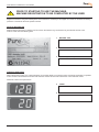
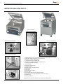
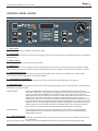
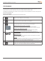
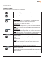
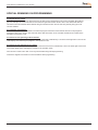
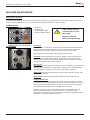
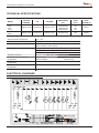
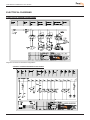
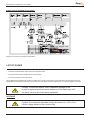
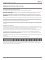
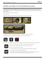
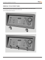
USER MANUAL
PREMIER & ULTRA SERIES
USER MANUAL PREMIER & ULTRA SERIES
This manual is for the PREMIER AND ULTRA series. The general instructions apply to the models in this category. PureVac
cannot be held responsible for any damage caused by deviating machine specifications.
This manual has been compiled with the utmost of care. PureVac accepts no responsibility for any errors in this
manual and/or the results of misinterpretation of this manual.
PureVac is not liable for damages and/or problems that arise from using spare parts that are not supplied by
PureVac
PureVac reserves the right to change specifications and/or spare parts without prior notification.
All rights reserved. No part of this publication may be reproduced by photocopy, printing or in any other way without prior
consent from PureVac
LIABILITY
1. We exclude all liability in so far as it is not provided for by law.
2. Our liability shall never exceed the total amount of the order in question.
3. Barring the generally applicable legal rules of public order and good faith we are not liable to pay for any damage of any sort
whatsoever, directly or indirectly, including business losses, to movable or immovable property, or to persons, either at the
opposing party as at third parties.
4. We are in any case not liable for damages arising from or cause by the use of the product supplied or by the unsuitability of it
for the goal for which the other party purchased it.
GUARANTEE
1. Subject to the following limitations we give 24 months guarantee on the products supplied by us. This guarantee is limited to
manufacturing faults that occur and does therefore not cover breakdowns involving any parts of the supplied product that are
exposed to any form of wear or usage.
2. The guarantee on parts or additions provided from third party suppliers is limited to the guarantee provided us by the third
party supplier.
3. The guarantee expires if the other party and/or third parties engaged by him use the supplied product incompetently.
4. The guarantee also expires if the other party and/or third parties engaged by him carry out activities on i.e. make
modifications to the supplied product.
5. If we replace parts in compliance with the obligations of this guarantee then the replaced parts become our property.
6. If the other party does not, not sufficiently, or not in a timely fashion fulfil any of the obligations arising from the agreement
reached between the parties then we are not obliged to provide this guarantee as long as the situation is occurring.
The stipulations of the guarantee and liability are part of the general terms and conditions of sale which will be sent to you if requested.
2
USER MANUAL PREMIER & ULTRA SERIES
CONTENT USER MANUAL
INTRODUCTION / LIABILITY / GUARANTEE
........................................
2
CONTENTS INSTRUCTION MANUAL
........................................
3
MACHINE REGISTRATION
........................................
4
IMPORTANT FOR INSTALLATION – READ THIS FIRST!!!!
........................................
5
IMPORTANT FOR USE – READ THIS FIRST!! !!
........................................
7
WARNING LABELS
........................................
8
IMPORTANT MACHINE PARTS
........................................
7
STARTING UP AND OPERATING
........................................
8
ON/OFF switch / Master switch . . . . . . . . . . . . . 8
Sleeper function . . . . . . . . . . . . . . . . . . . . . . . . . 8
Start machine . . . . . . . . . . . . . . . . . . . . . . . . . . . 8
Standard operating steps . . . . . . . . . . . . . . . . . 9
MACHINE CONTROL PANEL
........................................
10
Control panel versions . . . . . . . . . . . . . . . . . . . 10
Control panel layout . . . . . . . . . . . . . . . . . . . . . 11
Operation mode . . . . . . . . . . . . . . . . . . . . . 12-14
Program mode . . . . . . . . . . . . . . . . . . . . . . . . . 14
Other modes . . . . . . . . . . . . . . . . . . . . . . . . . . . 14
Operation Hours Counter . . . . . . . . . . . . . . . . 14
PROGRAMMING
........................................
15
Manual programming. . . . . . . . . . . . . . . . . . . . 15
Automatic programming . . . . . . . . . . . . . . . . . . 16
Special remarks on programming . . . . . . . . . . . 17
MACHINE MAINTENANCE
........................................
18
General . . . . . . . . . . . . . . . . . . . . . . . . . . . . . . . 18
Important before and during maintenance . . . 18
Standard maintenance schedule . . . . . . . . . . . 19
Vacuum pump maintenance . . . . . . . . . . . . . . 19
Conditioning Program . . . . . . . . . . . . . . . . . . . 19
Changing Oil / Filing up . . . . . . . . . . . . . . . . . . . 20
Changing the oil filter . . . . . . . . . . . . . . . . . . . . . 21
Inspect and change oil exhaust filter . . . . . . 21-22
Seal system maintenance . . . . . . . . . . . . . . 22-23
Silicone holder and lid gasket maintenance . . . 24
List of maintenance parts . . . . . . . . . . . . . . . . 25
TECHNICAL SPECIFICATIONS
........................................
26
ELECTRICAL DIAGRAMS
........................................
27-28
ERRORS CODES
........................................
29
PNEUMATIC DIAGRAMS
........................................
29
PROBLEM SOLVING
........................................
30
FACTORY SETTINGS CONTROL
........................................
31
REMARKS ON SPECIAL APPLICATIONS
........................................
32
Machine with gas flush system . . . . . . . . . . . . 32
Packaging liquid products . . . . . . . . . . . . . . . . 32
External vacuuming of food containers . . . . . . 33
MAINTENANCE SCHEDULE / NOTES
........................................
34
REMOVAL FRONT PANEL
........................................
35
3
USER MANUAL PREMIER & ULTRA SERIES
PRIOR TO STARTING TO USE THE MACHINE,
MACHINE REGISTRATION TO BE COMPLETED BY THE USER
Register the machine using the following data. This information is necessary if the supplier or PureVac is contacted concerning
questions or references about the specific machine.
DATA ON MACHINE TAG
Relevant data for answering questions can be found on the machine tag. The machine tag is located at the rear of the
machine. Note down the following data:
1.
MACHINE TYPE
2.
MACHINE NUMBER (MACHINE NO.)
3.
VOLTAGE (TENSION)
CONTROL PANEL DATA
When starting the machine, two codes first appear on the large display in succession before control panel switches to operation
mode. The first code indicates the model of the machine and the second code indicates the control software version.
Write both codes in the space below:
4
4.
CODE 1
5.
CODE 2
USER MANUAL PREMIER & ULTRA SERIES
IMPORTANT FOR INSTALLATION !!! READ THIS FIRST !!!
GENERAL
•
•
•
•
First read this manual carefully before the machine is put into operation.
This manual contains relevant information and instructions for starting up, maintenance and applications.
If problems arise with the machine that could have been avoided by referring to this manual then the guarantee expires.
PureVac wishes the customer lots of pleasure for an extended period from the purchase of the machine. If there are any
problems or questions then the customer can always approach the supplier or PureVac.
ENVIRONMENT
•
•
•
•
•
The machine must be moved or transported in an upright position. The machine may NOT be tilted as this can cause
damage to the pump.
Place the machine on a flat, level floor. This is essential for problem free operation of the machine.
Enough space must be left around the machine for good ventilation. The space must be at least 5 centimetres.
The ambient temperature in which the machine is operated must be between 5 0C and 30 0C. When operating the machine
in other ambient temperatures the user must contact the supplier or PureVac for advice.
NEVER place the machine directly next to a heat source or a steaming device (for example a combo-steamer, dishwasher or
stove)
POWER / EARTH
•
•
•
•
•
•
•
Check that the voltage stated on the machine tag is the same as the mains voltage.
Check the direction which the pump is turning when the machine is connected to a three phase power source.
Always connect the machine correctly to an earthed socket to avoid danger for fire or electrical shocks (earth connection is
green/yellow).
The power cable must always be free and nothing may be placed on it.
Replace the power cable immediately if damaged.
Always disconnect the power if there are problems with the machine or during maintenance, prior to starting work on the
machine.
If the machine is stationary for long periods then the power should always be disconnected..
VACUUM PUMP
•
•
•
•
Check before starting the machine if there is oil in the pump (see page 20). NEVER start the machine without oil in the pump.
Use the right type of oil for the pump (see page 21).
After moving and/or transporting the machine, always first check the oil level before re-starting operation.
When starting the machine for the first time or after a lengthy idle period first run the conditioning programme before
operating the machine (see page 19).
CONNECTING THE GAS FLUSH SYSTEM (if applicable)
•
NEVER use flammable gasses or gas mixtures containing too much oxygen. There is a danger of explosion when using the
aforementioned gasses. Accidents and/or damage caused by using abovementioned gasses void all liability on the part of
PureVac as well as the guarantee.
• The gas bottles must always be correctly secured. If the gas flush function and/or the machine is not in use then the main
cock of the gas bottle must always be closed.
• The pressure of the pressure reducing valve on the gas bottle may NEVER be set to more than 1 atmosphere/ATO. A higher
pressure may damage the machine.
• The diameter of the hose nipple connector for the gas bottle is 6 mm (Premier Series), and 8 mm for other machines. The
connector is at the rear of the machine.
For more information about the use of gas bottles, consult an authorised gas supplier
CONNECTING COMPRESSED AIR FOR EXTERNAL SEALING PRESSURE (if applicable)
•
The pressure from the compressor may NEVER be set to more than 1 atmosphere/ATO. A higher pressure may damage the
machine.
• Only dry compressed air may be used for the external seal pressure.
• The diameter of the hose nipple connector the compressor is 6 mm (rear machine)
For more information about the use of compressed air, consult an authorised gas supplier
5
USER MANUAL PREMIER & ULTRA SERIES
IMPORTANT FOR OPERATION !!! READ THIS FIRST !!!
GENERAL
•
•
•
•
Never pack products that can be damaged during or after vacuum packaging. Live oats may never be vacuumed.
Refer to this manual if in doubt as to the operation and/or functioning of the machine. If the manual does not offer a solution
consult the supplier or PureVac.
The guarantee and/or liability expires if damage is caused by repairs and/or changes made by you. In the case of
malfunctions contact the supplier or PureVac.
In the case of malfunctions always stop the machine and remove the power cable from the wall socket.
GENERAL MAINTENANCE
•
•
•
It is essential that the machine is serviced regularly to guarantee operation and to keep the machine in optimal condition. The
maintenance schedule is clearly defined on page 12. The guarantee automatically expires due to overdue or sloppy maintenance.
Always remove the power cable from the wall socket for maintenance work, the machine must be completely disconnected.
If there are doubts about the maintenance activities or if the machine fails to work correctly always contact the supplier or
PureVac.
TRANSPARENT LID
•
•
•
•
•
Never locate the machine near a heat source. This can cause damage to the lid (cracks).
Never place hot, sharp, or heavy objects on the lid. These can cause damage to the cover (cracks) in the long run.
Always clean the cover with solvent-free cleaning agents. Solvents can damage the lid.
Check at least once a week if there are cracks in the lid. If cracks are visible in the lid then the machine must IMMEDIATELY
be turned off and not used again until the lid has been replaced. Continuing to work with a cracked lid can cause the lid to
implode. All guarantees and/or liability expire in the case of accidents and/or damage caused by working with a cracked lid.
Replace the transparent cover every 4 years as a precautionary measure as a standard maintenance interval.
VACUUM PUMP
•
•
•
Regularly check the level and quality of the oil in the pump. If too little oil or the quality of the oil is bad (turbid), replace or top
up the oil before operating the machine (see page 20). Let the pump conditioning program run at least one full cycle before
replacing the oil (see page 20).
Use the right type of oil for the pump when replacing or topping up (see page 20).
Use the conditioning program at least once a week to enhance correct and long-lasting pump operation (see page 19).
USE OF GAS FLUSH SYSTEM (if applicable)
•
NEVER use flammable gasses or gas mixtures containing too much oxygen. Use thereof can cause risk of explosions. Accidents
and/or damage caused by using abovementioned gasses voids all liability on the part of PureVac as well as the guarantee.
• The gas bottles must always be correctly secured. If the gassing function and/or the machine is not in use then the main
cock of the gas bottle must always be closed.
• The pressure of the pressure reducing valve on the gas bottle may NEVER be set to more than 1 atmosphere/ATO. A higher
pressure may damage the machine.
For more information about the use of gas bottles, consult an authorised gas supplier
WARNING SIGNS ON THE MACHINE !!!
6
•
ONLY use the prescribed power supply
voltage.
•
Insert the plug firmly into the mains wall
socket.
•
Always connect the machine to an
earthed wall socket.
•
Always remove the plug during
maintenance or when the machine is
not in use for extended periods.
•
NEVER use flammable gasses or
gas mixtures containing too much
oxygen. Use thereof can cause risk of
explosions
•
Accidents and/or damage caused by
using abovementioned gasses void(s)
all liability on the part of PureVac as well
as the guarantee.
USER MANUAL PREMIER & ULTRA SERIES
IMPORTANT MACHINE PARTS
Vacuum chamber
Vacuum
chamber
8
7
3
9
1
Side
viewBOXER
Premier
Series
Side view
machines
view Ultra
Series
RearRear
view MARLIN
machines
17
12
18
10
13
16
11
12
14
Rear view
machines
Rear
viewBOXER
Premier
Series
18
17
14
16
15
13
11
1. Sealing bar(s) in vacuum chamber mounted seal pots with a click system
1. Sealing bar(s) in vacuum chamber mounted seal pots with a click system
2. Silicone holder(s) mounted on transparent lid
2. Silicone holder(s) mounted on transparent lid
3. Gas flush nozzles (if applicable)
) seal
3. Lid
Gasrubber
flush nozzles
applicable
4.
in lid(iffor
hermetic
4. Gas
Lid rubber
in lidfor
for opening
hermetic seal
5.
springs
lid after machine cycle
5. Gas springs for opening lid after machine cycle
6. Vacuum / Ventilation opening
6. Vacuum / Ventilation opening
7. Control panel
7. Control panel
8. Vacuum pressure meter
8. Vacuum pressure meter
9.
Switch
9. ON/OFF
ON/OFF Switch
10.
Master
switch
(only
Ultraseries)
series)
10. Master switch (only
MARLIN
11.
drainplug
plug
11. Oil
Oil drain
12.
fillplug
plug
12. Oil
Oil fill
13.
Oil
inspection
window
13. Oil inspection window
14.
cable
14. Power
Power cable
15.
holder
with
Premier
series)
15. Fuse
Fuse holder
with
fusefuse
(only(only
BOXER
series and
MARLIN 42 and 42 XL)
16.
bottle
connector
(if applicable)
16. Gas
Gas bottle
connector
(if applicable)
caution caution
max 1 Barmax 1 Bar
17.
17. Machine
Machine tagtag
18. Warning
Warning stickers
18.
stickers
ppearance of parts
and machines
can deviate from
Appearance
of parts
and machines
canillustrations
deviate from illustrations
7
USER MANUAL PREMIER & ULTRA SERIES
STARTING AND OPERATING THE MACHINE
ON/OFF SWITCH / MASTER SWITCH
The ON/OFF switch is used to turn the machine on and off before and after operation.
CAUTION – The ON/OFF switch does not completely turn off all power to the machine. With the Premier
series, and other models which run on 1 phase power, it is necessary to unplug the power cable from the
wall socket before the machine is completely without power. With the other Ultra models which run on 3
phase power, it is necessary to turn off the master switch before the machine is completely without power.
Ensure that the machine is completely without power during maintenance and repair activities.
Premier series
When the machine is turned on (with the ON/OFF switch), the pump only runs during the vacuum cycle.
Ultra series
When the machine is turned on (with the ON/OFF switch), the pump runs continuously. The 3 phase
pumps need more time to warm up and turning them on and off has a detrimental effect on their lifespan.
If the machine is turned on, but it is not used, the pump will automatically turned off after 10 minutes. This
to prevent overheating from the oil, and reduce unnecessary pollution from exhaust filters. We call this
function Sleeper function.
SLEEPER FUNCTION
On the models: Ultra the sleeper function id default switched on. This means if the machine is switched on
but not ued, the pump automatically switches of after 10 minutes. By closing the lid the cycle and the pump
will start simultaneously. Contact the supplier or PureVac for more information on the sleeper function.
START MACHINE
When the machine is connected and the master switch is switched to 1 (if applicable) then the machine
can be turned on using the ON/OFF switch. When starting the machine two codes first appear in
succession on the large display before control panel switches to operation mode.
The first code indicates the model of the machine. The second code indicates the control software version.
Note both codes on page 4 as they are important for the supplier or PureVac when making enquiries
and/or if any problems arise.
After switching to operation mode the machine is ready for use. If the machine is new or has been unused
for a longer period of time then it is advisable to run the pump conditioning program (15 minutes) to heat
up and clean the pump. For instructions on the conditioning program, see page 19.
After switching to the operation mode the display could read [ OIL ]. This means that the operating hours
counter is turned on and the set number of operating hours has elapsed. The hour counter is turned off by
default but the client or supplier can activate it as a reminder for regular maintenance activities.
When [ OIL ] is displayed the machine can be still be used as usual but it is advisable to either turn off the
hour counter or to reset it. More information on how to set or turn off the operating hours counter can be
found on page 14.
8
USER MANUAL PREMIER & ULTRA SERIES
STANDARD USER OPERATIONS FOR THE MACHINE
1. Turn the machine on with the ON/OFF switch. Heat up the pump with the condition program when machine has stood idle for
some time (instructions page 22).
2. Fill the vacuum bag with product. Select the correct format bag that easily fits around the product but is not too large for the
product. Ensure hygienic conditions during this operation. Packaging materials, product and hands must be clean and if
possible dry.
3. Lay the vacuum bag in the chamber or on the working plate. The open side must be laid over the
sealing bar or silicone holder. The bag may however not extrude from the chamber. If the product is
a lot lower than the height of the sealing bar or silicone holder then insertplates which are supplied
standard with the machine can be used. This makes the operation easier and reduces the cycle time.
4. The vacuum bag must be laid without folds over the sealing bar (Premier and Ultra)
5. For a gas flush system the opening of the vacuum bag must be pulled over the gas nozzles (see illustration).
6. Multiple vacuum bags can be placed over the sealing bar/silicone holder if the sealing bar/silicone holder is longer than the
vacuum bag. Vacuum bags may not however be laid on top of each other on the bar/holder. If there are multiple bars/holders
then all bars/holders can of course be used during the same cycle.
7. Use the [PROG] key to choose the desired program. See page 15 for instructions about programming.
8. Close the lid and the machine automatically runs through the full cycle of all activated functions. The lid opens automatically
when the last function “ventilation” has been completed.
9. If necessary the cycle can be partially or fully interrupted by pressing the [VACUUM STOP] key or the [STOP] key. The
[VACUUM STOP] key interrupts the active function (vacuum, gas flushing, sealing, or soft-air ventilation) and automatically
continues with the next function. The [STOP] key interrupts the entire cycle and goes immediately to the ventilation function.
10. After cycle completion, the packed product (or products) can be removed from the machine.
11. If the machine is equipped with a cut-off sealing system then the remaining flap on the vacuum bag can be torn off.
SAFETY and PRODUCT PROTECTION
The packing process can be partially or fully interrupted at all times:
• Stop active function, press on [VACUUM STOP] key
• Stop full machine cycle, press [STOP] key
OPTIMAL AND EFFICIENT PACKAGING RESULT
•
•
•
•
Use the correct size and good quality vacuum bags
Maximum 75% product filling in vacuum bag
Place vacuum bag fold free over sealing bar/silicone holder (use correct number in
insertplates in chamber)
Pull vacuum bag far enough over gas nozzles (for gas flush) so that no gas is lost and the
bag does not move during gas flushing
9
USER MANUAL PREMIER & ULTRA SERIES
MACHINE CONTROL PANEL
CONTROL PANEL VERSIONS
General
The digital control panels are implemented with 9 pre-select programs that can be individually set with
different function values (to be able to pack different products) Program 0 can not be set and is used
for servicing and testing. A program cycle is the complete program of set functions that the machine
runs through to package a product. The control panels are designed with a operation mode and a
program mode. The operation mode is used during operational activities for selecting the program
number with the required program cycle. The set values of the function program can also be seen in
the operation mode but not changed. The program mode is used to change the function values within
the programs.
The control panels are implemented standard with an automatic conditioning program for the regular
maintenance of the pump and two STOP keys for complete cycle interruption or for only active function
interruption. There are also a number of built-in service programs. Contact the supplier or PureVac for
more information about these programs.
Digital Time Control
The value of all active functions can be set for a certain time period. The vacuum function, gas
flush function (if installed), and soft air function can be set in whole seconds up to a maximum of 99
seconds. The seal function can be set with an interval of 0.1 seconds and a maximum of 6.0 seconds.
Digital Sensor Control
The value of the vacuum function and the gas flush function (if installed) can be set as a percentage of
the vacuum. This is the percentage of the under pressure in the vacuum chamber related to the outside
pressure 1 atmosphere/ATO (0%). The maximum vacuum percentage setting of the vacuum function
is 99%. The minimum vacuum percentage setting of the gas flush function is 30%. This means that the
chamber is flushed with gas to 30% under pressure in relation to 1 atmosphere. It is often expressed
as 70% is flushed with gas (99+% - 30% = 70%). The time for the soft air function can be set on
whole seconds (max. 99 seconds). The time for the seal function can be set on 0.1 seconds (max. 6.0
seconds).
The digital sensor control comes standard with the VACUUM PLUS function. The VACUUM PLUS
function is a time operated additional vacuum function for setting extra time after reaching the 99%
value of the vacuum function (only applicable if 99% is set for the vacuum function). This function
provides additional vacuum time for vacuuming any trapped air out of the package.
Contact the supplier or PureVac for information about special operating panels not shown above.
10
USER MANUAL PREMIER & ULTRA SERIES
CONTROL PANEL LAYOUT
0,6
0,4
0,8
0,2
-1
0
VACUUM
GASFLUSH
VAC
STOP
SEAL
SOFT-AIR
STOP
1. Small Display
Displays active program in operating and program modes.
2. Large Display
Displays the current value of the active function during the program cycle or the set value of the selected function in operation or
program mode.
3. PROG 0-9 Keys
Selects program number in operation or program mode.
4. REPROG Key
Switch from operation mode to program mode (for setting function values) and vice versa. After setting new function value(s)
within a selected program in program mode, this key must always be used to store the new values for the program in memory.
5. FUNCTION SELECT Key
Selects function within selected program in operation and program mode. The function is selected if the function light is
on in front of the function description under the large display.
6. CONDITIONING PROGRAM Key
Start the conditioning program for pump (duration 15 minutes). For instructions on the program, see page 19.
7. FUNCTION Lights
A light in front of the function indicates that the function is active during the program cycle or that the function is selected during
the operation or program modes.
Special Remark:
There is an additional time operated vacuum function available at digital sensor control, the
VACUUM PLUS function. This function is not displayed on the panel. The VACUUM PLUS function
can only be activated if the standard vacuum function is set to 99% VACUUM PLUS function
display during the cycle (if activated) : The vacuum indicator light remains on after 99% is reached
and during the time set for VACUUM PLUS. During the VACUUM PLUS vacuum cycle a dot
appears in the right lower corner of the large display. Display during operation and program mode :
If the VACUUM PLUS time is activated during the selected program then a dot appears in the lower
right-hand corner of the large display during the operation and program mode. If the functions are
selected using the function selection keys then the indicator light in front of VACUUM comes on
twice, and the vacuum percentage and VACUUM PLUS time are shown consecutively.
Special Remark
If the machine has the gas flush function implemented and the function is activated within the
selected program then a dot appears in the lower right hand corner of the small display when
selecting the program no..
8. + / STOP VACUUM Key
Function during cycle
Interruption of the active function during the program cycle. The cycle immediately continues with
the next function.
Function in program mode Raise the value of the selected function within the program selected in the program mode.
11
USER MANUAL PREMIER & ULTRA SERIES
CONTROL PANEL LAYOUT CONT.
9. - / STOP Key
Function during cycle
Terminates the program cycle completely. The cycle immediately switches to the ventilation
function.
Function in program mode` Lower the value of the selected function within the program selected in the program mode.
10. Vacuum meter
Displays the pressure in the vacuum chamber. See the following table for the relationship between the vacuum meter
and the percentage vacuum.
Position vacuum meter
Vacuum percentage
0
0
0.2
20
0.3
30
0.4
40
0.5
50
0.6
60
0.7
70
0.8
80
0.9
90
- 1.0
99+
11. ON/OFF Switch
The ON/OFF switch is used to turn the machine on and off before and after operation. The switch turns on all units in the
machine. Caution, the switch does not completely remove all power from the machine.
OPERATION MODE
When the machine is turned on, the machine switches to operation mode after displaying the two codes (see page 4).
The operation mode is the standard setting of the control panel for packaging products. Set values cannot be modified in
operation mode.
With the PROG key and function selection keys the set values within the various programs can be viewed. If the
machine is ready to package a product (the product is already in the chamber), then all that needs to be done is to
choose the program (PROG key) and close the lid. The program cycle starts automatically running through the set
functions in the program.
Description of the program cycle for digital time control
1. Select the program number with the PROG key and the small display.
If the selected programme is programmed with the active gas flush function then a dot appears in the lower right hand corner
of the small display.
2. Close the lid.
3. Vacuum function
The machine starts to vacuum the chamber.
The light in front of [VACUUM] goes on.
Large Display: decrementing time per second starting at the time set (max. 99 sec.).
Vacuum meter starts increasing to the left.
4. Gas flush function
(if installed)
Once the vacuum function has completed then the gas flush function starts to flush gas into
the vacuum chamber.
The light in front of [GAS] goes on.
Large Display: decrementing time per second starting at the time set (max. 99 sec.).
Vacuum meter starts decreasing to the right.
12
USER MANUAL PREMIER & ULTRA SERIES
CONTROL PANEL LAYOUT CONT.
5. Seal function
When the vacuum function or gas flush function (if installed) ends, the seal function starts to
seal the vacuum bag(s).
The light in front of [SEAL] goes on.
Large Display: decrementing time per 0.1 second starting at the time set (max. 6.0 sec.).
The reading on the vacuum meter stays the same.
6. Soft-air ventilation function After ending the seal function the soft air function starts to slowly ventilate the vacuum
(if installed)
chamber.
The light in front of [SOFT AIR] goes on.
Large Display: decrementing time per second starting at the time set (max. 99 sec.).
Vacuum meter starts slowly decreasing to the right.
7. Ventilation function
After ending the seal function or the soft air function (if installed) the ventilation function starts
ventilating the chamber to 1 atmosphere/ATO and the lid opens.
There are no longer any lights on in front of the functions.
Large Display: lines going up and down until the lid is opened.
The vacuum meter runs back to the right to zero and the lid opens automatically.
8. The product is packed and ready to remove.
Description of the program cycle for digital sensor control
1. Select the program number with the PROG key and the small display.
If the selected program is programmed with the active gas flush function then a dot appears in the lower right hand corner of
the small display.
If the selected program is programmed with the active VACUUM PLUS function then a dot appears in the lower right hand
corner of the large display.
2. Close the lid.
3. Vacuum function
The machine starts to vacuum the chamber.
The light in front of [VACUUM] goes on.
Large Display: incrementing percentage vacuum until the percentage set (max.. 99%) and a dot
in the lower right hand corner if the VACUUM PLUS function is activated.
Vacuum meter starts increasing to the left.
4. VACUUM PLUS function
(if installed)
The machine continues vacuuming the chamber after 99% value is reached.
The light in front of [VACUUM] goes on.
Large Display: decrementing time per second starting at the time set (max. 99 sec.). and a dot
in the lower right hand corner.
The vacuum meter will very slowly increment to the left (hardly noticeable).
Remark: can only be installed with a vacuum function whereby the value is set to the maximum
of 99%.
5. Gas flush Function
(if installed)
Once the vacuum function has completed then the gas flush function starts to flush gas into
the vacuum chamber.
The light in front of [GAS] goes on.
Large Display: decrementing percentage vacuum until the set percentage (min. 30%).
Vacuum meter starts decreasing to the right.
6. Seal function
When the vacuum function or gas flush function (if installed) ends, the seal function starts to
seal the vacuum bag(s).
The light in front of [SEAL] goes on.
Large Display: decrementing time per second starting at the time set (max. 6.0 sec.).
The reading on the vacuum meter stays the same.
7. Soft-air ventilation function After ending the seal function the soft air function starts to slowly ventilate the
(if installed)
vacuum chamber.
The light in front of [SOFT AIR] goes on.
Large Display: decrementing time per second starting at the time set (max. 99 sec.).
Vacuum meter starts slowly decreasing to the right.
13
USER MANUAL PREMIER & ULTRA SERIES
CONTROL PANEL LAYOUT CONT.
8. Ventilation function
After ending the seal function or the soft air function (if installed) the ventilation function starts
ventilating the chamber to 1 atmosphere/ATO and the lid opens.
There are no longer any lights on in front of the functions.
Large Display: lines going up and down until the lid is opened.
The vacuum meter runs back to the right to zero and the lid opens automatically.
9. The product is packed and ready to remove.
PROGRAM MODE
The program mode is used to change the function values within the programs. See page 15-17 for instructions on programming.
OTHER MODES
The control panel also includes a service mode. The conditioning program (see page 19) for the pump and the operation
hours counter are the functions most used in this mode.
Operation Hours Counter
One of the service functions is the operation hours counter in order to be able to automatically indicate regular service
requirements. This functions sets the number of hours that the pump runs (per 10 hours). Note that for Premier series the pump
does not run continuously. Once the number of hours set has been exceeded, the message [OIL] appears on the display (see
page 8). The machine can still be used as usual but the message will keep reappearing on the display.
The factory setting for the program operation hours counter is OFF (turned off). The following steps can be followed to activate
the operation hours counter or to reset it:
Press the FUNCTION SELECT Key for at least 3 seconds. After 3 seconds the number of operating hours (per 10
hours) will be displayed for about 2 seconds. After 2 seconds the originally set number of hours will be displayed
(per 10 hours). When the operation hours counter is turned off, the number of operating hours will not be
displayed, instead the message [OFF] will immediately appear after pressing the key for 3 seconds.
The original setting can be modified using the + and – keys (between 0 and 990 hours). If set to 0 then the next time [OFF] will
automatically be displayed. The new settings are stored by using the REPROG Key. The actual operation hours are then also
reset to zero.
After pressing the REPROG key, the control panel automatically switches over to operation mode.
14
USER MANUAL PREMIER & ULTRA SERIES
PROGRAMMING
The function values in a selected program number can be changed using either manual or automatic programming. For units,
range and limits of the function values refer to the previous chapter, MACHINE CONTROL PANEL.
10 programs can be selected and set, number 0 to 9. Note: program 0 cannot be programmed. The values in this program are
set for service and reference use.
MANUAL PROGRAMMING
Starting situation: machine is in normal operation mode and the lid is open.
A.
Select the correct program with PROG 0-9 key for setting function values.
Program number is displayed on the small display.
B.
Press REPROG key to switch into program mode.
The program number now starts to blink on the small display.
C.
Select the required function for programming with the FUNCTION SELECT Key.
The indicator lights will turn on for the active functions when selected.
VACUUM
GASFLUSH
Remark on Seal function for option 1-2 cut-offseal
At option 1-2 cut-offseal, the indicator SEAL lights up twice when selected
The first time is for setting the seal time and the second time for setting the cutting time.
SEAL
SOFT-AIR
D.
VAC
STOP
STOP
Remark on option Digital Sensor Control
At option sensor control, the indicator VACUUM lights up twice when selected.
The first time for the vacuum function (vacuum percentage)
The second time for the vacuum plus function (time duration), see pages 11,13
Digital Time Control
Set the amount of time required for the selected function by using the + and – keys.
Digital Sensor Control
Set the percentage of vacuum required or the amount of time required for the selected
function by using the + and – keys.
Remarks
Set values are displayed on the large display. The functions vacuum plus (sensor control),
gas flush and soft air can be turned off in the programme if required. For turning off a
function press the – key until OFF appears on the large display.
E.
Repeat steps C and D for setting other function values.
F.
Press the REPROG key after setting all relevant functions to store the changes in the
program. The control then automatically switches back to operation mode and the machine
is ready for use. The newly set values are now the new default values
15
USER MANUAL PREMIER & ULTRA SERIES
PROGRAMMING
AUTOMATIC PROGRAMMING
Starting situation: machine is in normal operation mode and the lid is open.
A.
Select the correct program with PROG 0-9 key for setting function values.
Program number is displayed on the small display.
B.
Press REPROG key to switch into program mode.
The program number now starts to blink on the small display.
Close the lid. The machine cycle starts automatically.
C.
VACUUM
VAC
STOP
D.
VACUUM
VAC
STOP
E.
GASFLUSH
VAC
STOP
F.
G.
VACUUM PLUS FUNCTION (only with digital sensor control)
Digital Sensor Control
Time is increasing. Press the STOP VACUUM Key at the required time. The machine cycle
automatically switches to the following function.
Remarks
The VACUUM PLUS function can only be de-activated (OFF) by manual programming. The
VACUUM PLUS function will only run when VACUUM function has been set at 99%.
GAS FLUSH FUNCTION (optional)
Digital Time Operation
Time is increasing. As soon as the vacuum meter gets to the required underpressure,
press the STOP VACUUM Key. The machine cycle automatically switches to the following
function.
Digital Sensor Control
The percentage vacuum decreases. As soon as the required value is reached press the
STOP VACUUM Key. The machine cycle automatically switches to the following function.
Remarks
The minimal under-pressure advised is 0.5 bar or 50% vacuum. The minimum under
pressure that can be set is 0.3 bar or 30%. GAS FLUSH function can only be de-activated
(OFF) by manual programming.
SEAL FUNCTION
Can only be programmed manually. For automatic programming, the set time length will be
run and the machine cycle will automatically carry on with the next function.
SOFT-AIR
VAC
STOP
16
VACUUM FUNCTION
Digital Time Control
Time is increasing. As soon as the vacuum meter gets to –1 press the STOP VACUUM
Key. The machine cycle automatically switches to the following function.
Remark Digital Time Control
Let the vacuum function run 2 to 4 seconds longer after reaching –1 on the vacuum meter
so that “trapped air” in the packaging is also extracted.
Digital Sensor Control
The percentage vacuum increases. As soon as the value 99% is reached press the STOP
VACUUM Key. The machine cycle automatically switches to the following function.
Remark
If full vacuum is not required press the STOP VACUUM Key when the required value has
been reached.
SOFT AIR FUNCTION / STORE FUNCTION VALUES IN PROGRAM
Digital Time and Sensor Control
Time is increasing. As soon as the desired setting is reached press the STOP VACUUM
Key. After this operation the machine cycle ventilation starts and the lid opens. The values
are automatically stored and control panel reverts automatically to the operation mode. The
machine is ready for use.
Remarks
The soft air function can only be de-activated (OFF) with manual programming.
USER MANUAL PREMIER & ULTRA SERIES
SPECIAL REMARKS ON PROGRAMMING
For Digital Sensor Control
The value which is set for the gas flush function is the final vacuum percentage in the vacuum chamber after flushing
gas. For example, the vacuum function is set to 99% and gas flush function is set to 60%. This means that after the
vacuum function the chamber will be flushed with gas until there is 60% vacuum and 40% (actually 39%) gas in de
vacuum chamber.
For automatic programming,
Ensure that all functions are activated in the selected program. Activation means that the function in the program is
assigned a value. If the value is OFF then that means that the function is not activated and will not be included in the
automatic programming cycle.
For machines with optional gas flush function,
If a program is setup with the active gas flush function then this is indicated by a dot in the lower right hand corner of the
small display when selecting the program in the operation mode.
For machines with optional sensor control,
If a program is setup with the active VACUUM PLUS function then this is indicated by a dot in the lower right hand corner
of the large display when selecting the program in the operation mode.
If the function’s value is OFF then it can only be activated using manual programming.
Contact the supplier or PureVac for more information about programming.
17
USER MANUAL PREMIER & ULTRA SERIES
MACHINE MAINTENANCE
GENERAL
Regular, thorough maintenance is essential for extending the machine’s life, for preventing malfunctions and for achieving
an optimal packaging result. If the machine is used intensively (more than 5 hours per day) then it is a professional service is
recommended every 6 months. In other cases one complete service per year is sufficient (depending on location, environment
and products).
There are however also small maintenance activities that must be carried out more regularly and that the user can do himself.
The following page contains an overview of these activities.
IMPORTANT BEFORE AND DURING MAINTENANCE
•
The machine must always be completely voltage free before any maintenance is carried out on it. Remove the plug from the
wall socket or put the master switch in the O position.
•
If the machine is not functioning properly or if it produces strange noises, turn it off immediately with the ON/OFF switch and
contact the supplier or PureVac.
•
If the machine is equipped with a gas flush system then always close the main cock during standard maintenance activities.
Always take care that the pressure on the pressure reducing valve on the gas bottle is never higher than 1 atmosphere/
ATO before, during and after the maintenance activities. A higher pressure may cause irreparable damage to the machine.
NEVER use flammable gasses or gas mixtures containing oxygen.
•
When cleaning transparent lids (if applicable), NEVER use cleaning agents containing solvents. Check at least once a week
if there are cracks in the lid. In case of cracks, turn off the machine immediately and contact the supplier or PureVac.
•
High pressure cleaning is not permitted for cleaning the machine. High pressure cleaning can cause considerable damage to
electronic and other parts of the machine.
•
Water may never be permitted to enter either the extraction nozzle of the chamber or the blow-off opening of the pump. This
would cause irreparable damage to the pump.
•
Larger services must always be carried out by an authorised supplier.
•
The Premier machines are designed for a maximum of 5 hours operation per day. Other machines are designed for a
maximum of 8 hours per day. The supplier or PureVac cannot be held responsible for any malfunctions or defects if these
operation time limits are clearly exceeded without consultation.
•
The machine must be moved or transported in an upright position. The machine may NOT be tilted as it can cause damage
to the pump.
•
The supplier or PureVac cannot be held responsible for any malfunctions or defects if the maintenance instructions in this
manual are not followed.
•
Contact the supplier or PureVac if there are any doubts or questions about maintenance or malfunctions.
18
USER MANUAL PREMIER & ULTRA SERIES
MACHINE MAINTENANCE
STANDARD MAINTENANCE SCHEDULE FOR THE MACHINE
Daily
• Clean the vacuum chamber, lid, and housing after use with a damp cloth.
• Make sure that no cleaning agents containing solvents are used.
• Make sure that no high pressure cleaner is used.
Weekly
• Check the oil level and replace or fill up oil when the oil is turbid or the oil level is too low. For instructions,
see page 20.
• Activate the conditioning program for the pump at least once a week.
• Inspect the sealing bar for damage. Replace teflon tape/sealing wire if the seal quality is no longer
sufficient or if the teflon tape/sealing wire is no longer tight and straight on the sealing bar. For
instructions, see page 23.
• Inspect the lid gasket and replace it when the gasket is damaged or stretched. For instructions, see page 24.
• Inspect the transparent lid (if applicable). When cracks are visible, turn off the machine immediately and
contact the supplier or PureVac.
Every Six Months
• Replace oil at least once every 6 months.
Yearly
• Inspect the oil exhaust filter for saturation. If saturated, replace the filter. For instructions, see page 21.
• Contact the supplier for a professional service
Four-yearly
• Replace transparent lid and the lid’s gas springs (if applicable)
• Replace membranes seal cylinder (if applicable)
VACUUM PUMP MAINTENANCE
It is very important to regularly service the pump to ensure extended and correct operation. The following activities are essential
for correct maintenance. If the machine is used regularly then it is advisable to have the pump fully inspected at least once
a year by the supplier to ensure extended and problem free operation. Contact the supplier or PureVac for more advice and
information.
Conditioning Program
The conditioning program ensures that the pump is thoroughly rinsed. During the program the pump and oil reaches
operation temperature so that the oil can better absorb any moisture and contaminants and filter them. The high
temperature enables any moisture in the pump to evaporate minimising the risk for rust spots.
The program lasts 15 minutes and it is advisable to run it at least once a week. Turn on the machine, press the key [conditioning
program], and close the lid. The program runs automatically. During the program the large display will display moving lines.
The program can be interrupted at any time using the [STOP] key. It is however important for the sake of good maintenance that
the program completes a full 15 minute cycle and therefore advisable only to interrupt the cycle for something urgent.
It is also advisable to run the program before using the machine for the first time, after the machine has been stationary for a
lengthy period of time, and especially prior to changing oil.
19
USER MANUAL PREMIER & ULTRA SERIES
MACHINE MAINTENANCE
Changing Oil / Filling Up
The oil level and oil quality must be checked at least once a week. The oil inspection window serves this purpose. Fill up the oil
level if it is too low. Replace the oil if it is turbid. Oil must be replaced at least once every 6 months.
PREMIER
BOXERSERIES
series
3
1
4
1. Oil fill plug
2. Oil drain plug
3. Oil inspection window
4. Oil level indicator sticker
Take care to use the
correct type of oil for
the pump
Beware of hot oil
fumes during drainage
2
MARLIN
/ FALCON / POLAR series
ULTRA
SERIES
1
Draining oil
If the oil is white or turbid when checked then it must be replaced. Before draining
off the oil let the conditioning program run a full cycle. The dirt and moisture is
absorbed by the oil and the oil becomes thinner making draining easier.
After the program has ended the drainage plug can be removed.
3
2
CAUTION, when unscrewing hot oil fumes can escape. The oil now drains from
the drain hole (an oil pan must be placed underneath). For the Premier series,
when the oil has drained, tilt the machine slightly so that all residual oil can drain
off. After draining the oil drain plug is replaced.
Filling up oil
After draining or if the oil level has dropped, oil needs to be filled up. The oil fill plug
must be removed with the correct size spanner. The pump can now be filled with
oil. Make sure that you add the correct amount (see table on page 24)
TAKE CARE to fill with small amounts at intervals. Fill the oil level to the top of the
oil level indicator sticker.
TAKE CARE to replace the oil filter before adding the new oil (see page 24)
Oil types and amounts
It is important to use the correct type and quantity of oil for the pump. The wrong
type or too much oil could damage the pump. The ambient temperature where the
machine is operated is also important for the type of oil. See amounts and types
with related ambient temperatures in the table on the next page.
Examples of supplier brands for the standard types of oil are Shell Vitrea, Aral
Motanol GM, BP Energol CS, or Texaco Regal R+ O with related viscosity
numbering. If the machine is used outside normal specifications regarding ambient
temperature, contact the supplier or PureVac.
20
USER MANUAL PREMIER & ULTRA SERIES
MACHINE MAINTENANCE
Machine Type
Pump
Capacity
Filling (litres)
Standard Oil type
10 - 30 °C
“Cold” Oil type
5 - 10 °C
“Hot” Oil type
30 - 40 °C
Premier 1635
016 m3/h
0.4
Viscosity VG 32
VM 32
VS 32
Premier 2142 / 2141-2
021 m3/h
0.4
Viscosity VG 32
VM 32
VS 32
Ultra 6352-2
063 m3/h
1.0
Viscosity VG 100
VM 100
VS 100
Machines are supplied with standard type oil.
The capacity of models with a 063 m3/h pump and 60Hz voltage, is 2.0 litre instead of 1.0 litre.
Changing the oil filter
The pumps of all models except the Premier series have oil filters. When replacing the oil the filters
must also be replaced. The oil filter is screwed to the rear of the oil exhaust filter housing.
When replacing the oil, it is first drained off. The old filter is then screwed off and replaced by a new one.
The pump can now be filled with new oil.
For the correct type of oil filters refer to the list of maintenance parts on page 29.
Inspect and change oil exhaust filter
There are one or more oil exhaust filters in the pump which absorb and filter oil vapours. The filters will become saturated after
a period of time and need to be replaced. This is on average between 12 and 18 months. When the filters are saturated it is no
longer possible to achieve maximum vacuum.
Filter housing types
016-021 m3/h
040-063-100 m3/h
•
Filter housings can be located at
the side or behind the machine
•
Appearance can vary depending
on the model (multiple housings
on pump or multiple filters in
one housing)
160-300 m3/h
21
USER MANUAL PREMIER & ULTRA SERIES
Change oil exhaust filter(s)
Open rear or side of
machine for pump
Screw the cover(s)
from the filter
housing)
The filter(s) is/are
visible behind a
tensioner
Release the
tensioner(s) with a
spanner
• Place and tension the
new filter (take care that
the gasket is correctly
positioned) in the housing
• Screw the cover back onto
the housing
• Screw the back or side plate
on the machine
Remove tensioner(s)
and filter(s) from the
housing
Take care that the
filter gasket does not
remain behind when
removing the filter
• Pumps and housing can have a different appearance but the principle of replacing remains the same.
• Take care that the correct type of filter is used for the pump type, see page 25 for the correct type of filter for the type of pump
• It is advisable to have the suppler do this service.
SEALING SYSTEM MAINTENANCE
All or some of the following sealing systems are possible in the Premier/Ultra series. It is essential
to know which sealing system is applicable to the relevant machine.
DOUBLE SEAL
2 x 3,5 mm seal
Servicing the sealing bar is almost identical for all systems. The seal quality is partially dependent on the maintenance of the
sealing bar and contra-bar (silicone holder). The main maintenance activities are the daily cleaning of the sealing bar and the
silicone holder with a damp cloth and a weekly inspection of the bars with replacement of the sealing wire, teflon tape or silicone
rubber if irregularities appear on top of the bar or the seal quality is insufficient.
The average maintenance cycle of the sealing bar (teflon tape / sealing wire) is at least once every 3 months.
(This indication refers to regular use of the machine, on average 8 hours per day and packaging standard products with
standard vacuum packaging materials. No rights can be derived from this indication)
22
USER MANUAL PREMIER & ULTRA SERIES
Replace sealing wire and teflon tape
1.
1. Remove the sealing bar(s) from the holders (in the chamber or lid) by
releasing
click bar(s)
system
Remove
thethe
sealing
fr or by unscrewing the screws.
system or by unscrewing the
2. Remove the teflon tape from the sealing bar.
2.
3.
Remove teflon tape
4.
5.
Unscrew and remove
sealing wires
6.
7.
8.
Replace the teflon tape
9.
Remove the teflon tape from
3. The old sealing wires and cut-off wires (if applicable) can be removed by
unscrewing the clamp (see illustration) and pulling the wires from the grooves.
The old sealing wires and cu
(see the
illustration)
andthat
p is attached to the top of the sealing bar and
4.clamp
Remove
teflon tape
stick a new piece of teflon tape to the bar of the same length after having
Remove
the teflon
tape thatthe bar with a dust free cloth.
degreased
and cleaned
teflon tape to the bar of the s
5.dust
Cutfree
a new
peace of sealing wire or cut-off wire to the size of the sealing beam
cloth.
plus about 15 cm (± 6 inches). If 2 sealing wires or an extra cut-off wire is on
thea sealing
beam
then a second
sealing wire or cut-off wire must of course be
Cut
new peace
of sealing
w
cut.
cm (± 6 inches). If 2 sealing
second sealing wire or cut-o
6. Place the end of the wire or wires through the groove(s) on the side of the
sealing beam and screw the wires to the bottom.
Place the end of the wire or
thethe
wires
to the
7.screw
Place
sealing
barbottom
top down in a vice and pull the sealing wire or wires
through the other side of the groove(s) on the sealing beam.
Place the sealing bar top dow
8.side
Pullofthe
tight on
withthe
a pair of pliers and screw them down at the same time.
thewires
groove(s)
Ensure that the wire (wires) is (are) pulled taught and straight with the help of
a pair
of pliers
Pull
the wires
tightbefore
with athe
pawires are screwed down.
the wire (wires) is (are) pulle
9. It is handy to use a pair of adjustable pliers as a lever for optimal wire tension.
wires are screwed down.
Place one end of the sealing beam in the vice and stretch the wire (wires) by
pressing down the bar.
It is handy to use a pair of ad
of Cut
the sealing
beam in the
10.
off the extruding
wirevi end(s) on both ends after having screwed it tight.
10. 11.Cut
offathe
extruding
wire
en as long as the sealing bar plus about 5 cm (± 2
Cut
piece
of teflon
tape
inches).
11. Cut a piece of teflon tape as
12. Stick the new teflon tape straight over the new sealing wire (wires). Ensure
thatthe
thenew
teflon
is straight
on the sealing bar and that the sticky part is stuck on
12. Stick
teflon
tape stra
the side.
Ensure
thatbar
thean
teflon is stuck on the bar smoothly and without folds.
straight
on the
sealing
Screw down new wires
onto clamping plate
is stuck on the bar smoothly
13. Cut the teflon tape off so that the sticky part does not get stuck on the sides of
the clamps but that the teflon extends over the top of the clamps.
13. Cut the teflon tape off so tha
that
the teflon
extends
t in the machine. Ensure that the sealing beam is
14.
Place
the sealing
barover
back
properly clicked onto the holders or that the screws are firmly screwed in.
14. Place the sealing bar back in
onto the holders or that the s
Special remark bi-active sealing system The sealing wire must
be accurately placed on the upper and lower beams so that the
sealing wires line up with each other exactly during sealing
Pull wires taught using a
pair of pliers and a vice
and screw the wires down
on the clamping plate.
See page 25
for correct parts and quantities
Cut off the ends of the sealing wire and stick
Teflon tape over the sealing beam without folds
23
USER MANUAL PREMIER & ULTRA SERIES
SILICONE HOLDER AND LID GASKET MAINTENANCE
Replace the rubber silicone holder
The silicone holder must be inspected weekly for irregularities on
the silicone rubber (mainly caused by burning by the sealing wire). If
irregularities appear then the silicone rubber must be replaced.
Average maintenance cycle for silicone rubber is at least once every
6 months (This indication refers to regular use of the machine with
standard products. No rights can be derived from this indication)
1. Remove the old silicone rubber from the holder.
2. Cut a new piece of silicone rubber the same size as the old one.
The same size is very important, too short or too long will cause
problems with sealing.
3. Place the new piece in the silicone holder. Ensure that the silicone
rubber is completely and evenly placed in the groove. It is also
important that the surface of the silicone rubber is smooth after it
is in place and is shows no signs of tension.
Replace lid gasket
The lid gasket ensures that the vacuum chamber is completely
sealed during the machine cycle. This is essential for achieving
a maximum vacuum. The lid gasket wears due to the extreme
pressure differences and must be replaced regularly. Inspect the lid
gasket weekly for tears or damage.
Average maintenance cycle for lid gasket is at least once every 6
months (This indication refers to regular use of the machine, on
average 8 hours a day and with standard products. No rights can be
derived from this indication)
De length of the new lid gasket is determined by using the old
gasket. If the lid rubber is too short or too long it can cause problems
closing the lid or leak.
The rubber must be placed evenly and without tension in the holder.
The ends must be cut straight and must be laid tightly against each
other to avoid leakage.
24
Ensure that the ends of the
lid rubber connect up closely
USER MANUAL PREMIER & ULTRA SERIES
LIST OF SERVICE PARTS
VACUUM PUMP PARTS
BUSCH VACUUM PUMPS
PureVac MODELS
3
016m /h
Premier 1635
021m3/h
Premier 2142 / 2141-2
3
063m /h – 50Hz
Ultra 6352-2
BUSCH
016m3/h
3
STANDARD OIL
OIL FILTER
OIL MIST FILTER
Type
PureVac
Reference
Litres
Type
PureVac
Reference
Type
PureVac
Reference
Amount
VG 22
0439510
0.40
-
-
50-60Hz
0939003
1
021m /h
VG 32
0439510
0.40
-
-
50-60Hz
0939005
1
063m3/h – 50Hz
VG 100
0439520
1.0
040-063-100
0939090
50Hz
0939011
1
SEAL SYSTEMS
PARTS
SPECIFICATIONS
PureVac
Reference
QUANTITY
Teflon Tape
46 mm teflon tape
0305515
length sealing bar + 5 cm
Double Seal
2 x 3.5 mm round wire
0305000
2 wires length of sealing beam + 15 cm
LID GASKET
MODELS
PureVac
REFERENCE
LENGTHS PER MODEL (in cm)
Premier SERIES
0320215
Premier 1635
Premier 2142
Premier 2141-2
175
190
210
Ultra SERIES
0320210
Ultra 6352-2
250
Lengths specified are always a little longer and must be cut to the correct length.
25
USER MANUAL PREMIER & ULTRA SERIES
TECHNICAL SPECIFICATIONS
VACUUM
CHAMBER
LID
HOUSING
Premier SERIES
1635
2142
2141-2
Stainless-steel
Transparent
Stainless-steel
Ultra SERIES
6352-2
Stainless-steel
Transparent
Stainless-steel
MODEL
DIMENSIONS
(mm)
PUMP
(m3/h)
450x525x385
490x525x430
490x610x445
016
021
021
700x690x1030
063
Specifications may deviate with optional models
Standard ambient temperature
5°C – 30°C
For deviating ambient temperatures
see page 24 for special oil specifications
Maximum use per day
Premier series 5 hours per day
Other machines: 8 hours per day
Electricity
Voltage: see machine tag
Frequency: see machine tag
Power: see machine tag
Electrical connection
Maximum fluctuation ± 10% of the official registered voltage
Gas bottle connector diameter
(if applicable)
Premier series
OTHER MODELS
Maximum pressure gas bottle connector
(if applicable)
1 ATO
External seal pressure connection
(if applicable)
diameter 6 mm
Sound level
< 70 DB
ELECTRICAL DIAGRAMS
CONTROL CURRENT DIAGRAM PREMIER SERIES
26
diameter 6 mm
diameter 8 mm
FINAL
VACUUM (%)
99.80%
99.98%
USER MANUAL PREMIER & ULTRA SERIES
ELECTRICAL DIAGRAMS
POWER CIRCUIT DIAGRAM PREMIER SERIES
Diagrams are shown for standard configurations.
CONTROL CURRENT DIAGRAM ULTRA SERIES
27
USER MANUAL PREMIER & ULTRA SERIES
POWER CIRCUIT DIAGRAM ULTRA SERIES
Diagrams are shown for standard configurations.
LIST OF FUSES
•
Fuses are located where the power enters the component board
•
Fuses are been located on transformers (control and seal)
•
Two fuses are placed on the control circuit.
Due to different mains voltages and machine models there is a variety of fuse types that can be present in the machine. Refer to the
specifications of the relevant component for the correct types and values of fuses for replacement, or contact the supplier or PureVac.
Caution, to avoid fire and/or other irreparable damage to the
machine, replacement fuses must always be of the same type with
the same value as the fuses being replaced!!
VOLTAGE
Caution, the maximum allowable voltage fluctuation is ± 10% of the
official voltage stated on the machine tag.
28
USER MANUAL PREMIER & ULTRA SERIES
ERROR CODES
The controls are programmed with a number of error codes. These error codes are intended to give the user / dealer a clear indication of
what the possible cause might be why starting or packaging is not working as expected.
F1: This code indicates that the cycle (cover switch) will be interrupted prematurely.
Example: the cover of the machine closes after starting, but before sufficient vacuum is present to keep the cover closed
the operator lets go of the cover. The F1 code will now be shown on the display. In a time-controlled machine, the time for gassing
is set in such a way that the entire chamber is gassed and the cover opened without sealing taking place. Here too the F1 code will
immediately be shown on the display. This message will never be shown directly after the controls are started, but during the course of
the cycle.
F2: This code indicates that the sensor is not working properly.
When the controls are started, the condition of the sensor is checked. If the feedback data of the sensor are not correct, F2 is shown on
the display. This message will be shown directly after the sensor controls are started.
RP-: This message will be shown when, due to circumstances, the controls are unable to retrieve the programme values. The word
‘circumstances’ means peak tensions or a tension drop during starting. When such a situation occurs, the print will start with this message
and go no further. Two options exist now: the machine can be switched off and on again to see if the problem repeats itself or the reprog
key can be pressed. By operating the reprog key, the controls will use the factory settings to start. The programme values set by the client
will be cancelled as a result. This message will be shown directly after the controls are started.
If one or more of the above messages continue to occur regularly or cause a direct problem, we advise you to contact your dealer.
PNEUMATIC DIAGRAM
29
USER MANUAL PREMIER & ULTRA SERIES
PROBLEM SOLVING
PROBLEM
Machine does not work
CAUSE
• The plug is not plugged into the wall
socket.
• The main fuse is burnt.
• The ON/OFF switch’s contact block
has come loose.
• The circuit board fuse is burnt.
SOLUTION
• Plug the plug into the wall socket.
• Replace the fuse
(Ensure the correct value).
• Check this and if necessary
re-fasten it.
• Disassemble the front panel and
replace the fuse.
Machine does not work Operating panel
is on
• The control transformer fuse is burnt. • Check this and if necessary replace it.
• The micro-switch that is activated
• The micro-switch must be properly
adjusted or replaced
when the lid is closed is disordered or
faulty.
• There is an internal malfunction.
• Consult the supplier.
Transparent lid does not open
automatically
• The gas spring is faulty
• Consult the supplier.
Final vacuum is insufficient
• The set vacuum time is too short.
• There is too little oil in the vacuum
pump.
• The extraction hole at the back of the
vacuum chamber is partially covered
by the vacuum bag during extraction
• The lid gasket is worn.
• The oil is contaminated
• Extend the vacuum time.
• Check the oil level and top up if
necessary (Note the type and quantity).
• Place the vacuum bag closer to the
sealing beam.
• The oil exhaust filter is saturated.
• Replace the lid gasket.
• Replace the oil (Note the type &
amount).
• Replace the oil exhaust filter /
Consult the supplier.
The machine builds up a vacuum slowly
• The pump’s extraction filter is blocked.
• The oil exhaust filter is saturated.
• Consult the supplier.
• Replace the oil exhaust filter /
Consult the supplier.
The vacuum bag is not properly and/or
correctly sealed.
• The vacuum bag is being placed
incorrect on the sealing bar.
• Place the vacuum bag neatly and
smoothly on the sealing bar. Ensure
that the opening of the bag is always
within the vacuum chamber.
• Adjust the sealing time longer or
shorter.
• Replace the silicone rubber.
• The sealing time is too long or too
short.
• The silicone rubber in the silicone
holder is damaged or worn.
• The teflon tape is damaged.
• The inside of the vacuum bag
opening is contaminated or greased.
The amount of gas in the vacuum bag is
insufficient (optional).
• The gas bottle is empty or nearly empty.
• The gas bottle is still closed.
• Gas flush time is too long or too short.
• The gas flush pressure is incorrectly
set.
• Replace the Teflon tape
• Clean the vacuum bag’s opening.
• Replace the gas bottle.
• Check if the valve on the gas bottle is
closed. If so, open it.
• Shorten or extend the gas flush time.
• Check if the manometer or the
secondary pressure of the gas is set
to 1 atmosphere (1-ATO).
WARNING! The pressure of the gas
mixture may never be more
than 1 atmosphere/ATO.
In the case of other problems or questions contact the supplier or PureVac.
30
USER MANUAL PREMIER & ULTRA SERIES
DIGITAL TIME CONTROL FACTORY SETTINGS
Program
0**
1
2
3
4
5
6
7
8
9
Vacuum time
30
25
20
15
10
30
25
20
20
15
Gas flush time*
OFF
OFF
OFF
OFF
OFF
5
5
10
15
15
Sealing time
2.5
2.5
2.5
2.5
2.5
2.5
2.5
2.5
2.5
2.5
Soft-air time*
3
3
2
2
2
OFF
OFF
2
OFF
OFF
* Only applicable if the machine is equipped with the options in question.
If the machine is not equipped with the gas flush system and/or soft air ventilation then these options will not be available on
the control panel.
** Program 0 cannot be modified
DIGITAL SENSOR CONTROL FACTORY SETTINGS
Program
0**
1
2
3
4
5
6
7
8
9
Final vacuum pressure %
99
90
99
99
99
80
90
50
90
60
Vacuum plus time
15
OFF
15
10
10
OFF
OFF
OFF
OFF
OFF
Final vacuum pressure %
after gas flush*
OFF
OFF
80
70
60
50
80
OFF
80
30
Sealing time
2.5
2.5
2.5
2.5
2.5
2.5
2.5
2.5
2.5
2.5
Soft-air time*
3
3
2
2
2
OFF
OFF
2
OFF
OFF
* Only applicable if the machine is equipped with the options in question.
If the machine is not equipped with the gassing system and/or soft air ventilating then these options will not be available on
the operating panel.
** Program 0 cannot be modified
CUSTOMER SETTINGS TO BE FILLED IN
Program
0
Vacuum time Final
vacuum pressure %
99
1
2
3
4
5
6
7
8
9
Vacuum plus time
15
Gas flush time* Final
vacuum pressure % after
gassing*
OFF
Sealing time*
2.5
Soft-air time*
3
31
USER MANUAL PREMIER & ULTRA SERIES
REMARKS ON SPECIAL APPLICATIONS
MACHINE WITH GAS FLUSH SYSTEM (if applicable)
If the machine is equipped with the gassing system then the following remarks are important :
NEVER USE GAS MIXTURES WITH MORE THAN 20% OXYGEN AND OR OTHER EXPLOSIVE GASSES. THIS COULD
CAUSE FATAL EXPLOSIONS.
NEVER USE SEPARATE GAS BOTTLES WITH A MIXER WHEREBY ONE OF THE BOTTLES IS ONLY FILLED WITH
OXYGEN. MALFUNCTIONING OF THE MIXER OR IF THE OTHER BOTTLE WERE TO BE EMPTY COULD CAUSE FATAL
EXPLOSIONS.
All guarantees and/or liability expire in the case of accidents and/or damage caused by using oxygen or other explosive gasses.
The maximum gas pressure that can be set in the packaging is 35% (-0.35 bar on the vacuum meter). This means that there is
65% gas and 35% vacuum (under pressure) in the packaging. If a higher gas pressure results in insufficient seal quality contact
the supplier or PureVac for more information about connecting external seal pressure.
PureVac recommends checking the pressure and amount of gas in the gas bottles regularly. Ensure that the gas bottle(s) is(are)
correctly anchored. Always turn off the main cock on the gas bottle if the machine is not in operation or if the gas flush function
is not active.
PACKAGING LIQUID PRODUCTS
The machines can be also used for packaging liquid products like soups or sauces. In this process the vacuum process must be
carefully monitored (only possible with transparent lid or lid with inspection window). The [STOP VACUUM] key must be pressed
as soon as bubbles appear in the product; the saturation point (same as boiling point) has then been reached.
Settings for programs for packaging liquid products can best be programmed using automatic programming (see page 16-17).
The saturation point of liquids is reached at a certain ratio line of low pressures and high temperatures (see the example
table for water below). The saturation point will be reached sooner in the vacuum process when packaging liquids with a high
temperature (the amount of vacuum will therefore be less).
PureVac recommends therefore to first cool liquid products before packaging. By so doing an optimal vacuum can be achieved
for the product.
Saturation point of water – relation between the pressure and temperature of the water
Vacuum pressure [mbar]
1000
800
600
400
200
100
50
20
10
5
2
Boiling Point Temperature [°C]
100
94
86
76
60
45
33
18
7
-2
-13
A handy tip when packaging liquid products is to use a liquid insert plate so that the product remains at the bottom of the
packaging during the vacuuming process and there is less risk of liquid splashing out of the packaging. Contact the supplier or
PureVac for more information about the liquid insert plate
32
USER MANUAL PREMIER & ULTRA SERIES
EXTERNAL VACUUMING OF FOOD CONTAINERS (if applicable)
The Premier and Ultra series can be equipped with an option for externally vacuuming special food containers. This system can
vacuum special containers for longer storage life of the (food) products in the dish. The container has a special lid with valve.
Contact the supplier or PureVac for more information about the containers. The system for the machine consists of a hose with
vacuum applicator.
Operation External Vacuuming Food Containers
1. Start the machine
2. Place the hose connector over the extraction opening of the vacuum chamber of the machine
3. Check that the s
vacuum applica
hose (closed po
3. Check that the sliding valve on the vacuum applicator is on the side of the hose (closed position).
4. Press the PROG 0-9 Key until [E] (External Vacuuming) appears on the small display.
5. Place the vacuum applicator over the valve of the container and slide the sliding valve towards the lid to open the valve.
6.Press the + Key. The vacuum pump starts to run and the container is vacuumed.
VAC
STOP
7. When the vacuum meter reaches –1 then the container is fully vacuumed.
8. Press the – Key to stop the vacuum pump
9. The vacuum applicator can now be removed from the lid by sliding back the sliding valve.
10. The container is now ready for storage and/or stock.
STOP
11. If the machine needs to be used for normal applications then the hose can be removed from the
extraction opening and the required program chosen using the PROG 0-9 Key.
33
USER MANUAL PREMIER & ULTRA SERIES
NOTES / MAINTENANCE SCHEDULE
DATE
34
CARRIED OUT BY WHOM?
WHAT DONE ?
REMARKS ?
USER MANUAL PREMIER & ULTRA SERIES
REMOVAL TOOLS FRONT PANEL
With every machine we ship-out we enclose two special tools to make it possible to remove the front panel.
The tools slide in the slots at the bottom side of the front panel.
Now lift it a little and pull it towards you.
35
NATIONAL HEAD OFFICE
156 Swann Drive, Derrimut, VIC 3030
Phone: 03 8369 4600
Fax: 03 8369 4699
Email: [email protected]
EQUIPMENT SALES
Phone: 1800 035 327
Fax: 1800 808 954
VIC/TAS SALES SHOWROOM & DEMONSTRATION KITCHEN
96-100 Tope Street, South Melbourne, VIC 3205
Phone: 03 8369 4600
Fax: 03 8699 1299
Email: [email protected]
NSW/ACT SALES SHOWROOM & DEMONSTRATION KITCHEN
Unit 20/4 Avenue Of The Americas, Newington, NSW 2127
Phone: 02 9748 3000
Fax: 02 9648 4762
Email: [email protected]
QLD/NT SALES SHOWROOM & DEMONSTRATION KITCHEN
1/62 Borthwick Avenue, Murarrie, QLD 4172
Phone: 07 3399 3122
Fax: 07 3399 5311
Email: [email protected]
WA SALES
Unit 4 / 35 Westchester Road, Malaga, WA 6090
Phone: 08 9248 9290
Fax: 08 9248 1903
Email: [email protected]
SA SALES
Phone: 0409 340 015
Email: [email protected]
EQUIPMENT SERVICING (24/7)
Phone: 1800 810 161
Fax: 03 8369 4696
Email: [email protected]
EQUIPMENT SPARE PARTS
Phone: 1300 739 996
Fax: 03 8369 4696
Email: [email protected]
TECHNICAL PHONE SUPPORT
Phone: 1300 309 262
Fax: 03 8369 4696
Email: [email protected]
V1 - 230513
www.comcater.com.au