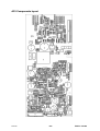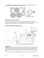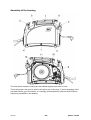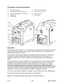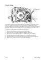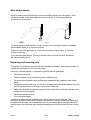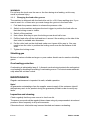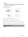
1
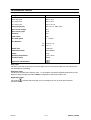
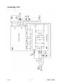
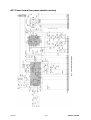
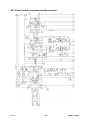
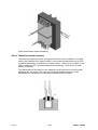
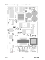
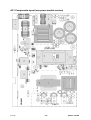
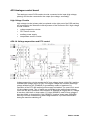
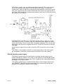
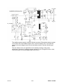
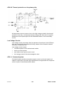
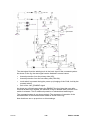
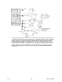
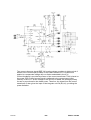
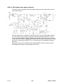
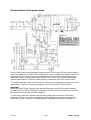
CaddyR
Mig C160i
Service manual
0349 300 094
101222
Valid for serial no. 924--xxx--xxxx
READ THIS FIRST . . . . . . . . . . . . . . . . . . . . . . . . . . . . . . . . . . . . . . . . . . . . . . . . . . . . . . . . . . . . . . . . .
INTRODUCTION . . . . . . . . . . . . . . . . . . . . . . . . . . . . . . . . . . . . . . . . . . . . . . . . . . . . . . . . . . . . . . . . . . .
TECHNICAL DATA . . . . . . . . . . . . . . . . . . . . . . . . . . . . . . . . . . . . . . . . . . . . . . . . . . . . . . . . . . . . . . . . .
WIRING DIAGRAM . . . . . . . . . . . . . . . . . . . . . . . . . . . . . . . . . . . . . . . . . . . . . . . . . . . . . . . . . . . . . . . . .
Component description . . . . . . . . . . . . . . . . . . . . . . . . . . . . . . . . . . . . . . . . . . . . . . . . . . . . . . . . . .
Caddyr Mig C160i . . . . . . . . . . . . . . . . . . . . . . . . . . . . . . . . . . . . . . . . . . . . . . . . . . . . . . . . . . . . . . .
DESCRIPTION OF OPERATION . . . . . . . . . . . . . . . . . . . . . . . . . . . . . . . . . . . . . . . . . . . . . . . . . . . . .
AP1 Power board (two power module version) . . . . . . . . . . . . . . . . . . . . . . . . . . . . . . . . . . . .
AP1 Power board (one power module version) . . . . . . . . . . . . . . . . . . . . . . . . . . . . . . . . . . . .
AP1:1. EMI mains filter . . . . . . . . . . . . . . . . . . . . . . . . . . . . . . . . . . . . . . . . . . . . . . . . . . . . . . . . . . . .
AP1:2. Pre--charge circuit . . . . . . . . . . . . . . . . . . . . . . . . . . . . . . . . . . . . . . . . . . . . . . . . . . . . . . . . .
AP1:3. Two--switch forward converter . . . . . . . . . . . . . . . . . . . . . . . . . . . . . . . . . . . . . . . . . . . . . . .
AP1:4. Current sense transformer . . . . . . . . . . . . . . . . . . . . . . . . . . . . . . . . . . . . . . . . . . . . . . . . . .
AP1:5. High frequency transformer . . . . . . . . . . . . . . . . . . . . . . . . . . . . . . . . . . . . . . . . . . . . . . . . .
AP1:6. Thermal protection sensors . . . . . . . . . . . . . . . . . . . . . . . . . . . . . . . . . . . . . . . . . . . . . . . . .
AP1 Components layout (two power module version) . . . . . . . . . . . . . . . . . . . . . . . . . . . . . .
AP1 Components layout (one power module version) . . . . . . . . . . . . . . . . . . . . . . . . . . . . . .
AP2 Analogue control board . . . . . . . . . . . . . . . . . . . . . . . . . . . . . . . . . . . . . . . . . . . . . . . . . . . . .
High Voltage Circuits . . . . . . . . . . . . . . . . . . . . . . . . . . . . . . . . . . . . . . . . . . . . . . . . . . . . . . . . . . . . . .
AP2:1H. Voltage supervision and PFC control . . . . . . . . . . . . . . . . . . . . . . . . . . . . . . . . . . . . . . . .
AP2:2H. Auxiliary power supply . . . . . . . . . . . . . . . . . . . . . . . . . . . . . . . . . . . . . . . . . . . . . . . . . . . .
AP2:3H. Thermal protection on the primary side . . . . . . . . . . . . . . . . . . . . . . . . . . . . . . . . . . . . . .
Low Voltage Circuits . . . . . . . . . . . . . . . . . . . . . . . . . . . . . . . . . . . . . . . . . . . . . . . . . . . . . . . . . . . . . .
AP2:1L. Command system . . . . . . . . . . . . . . . . . . . . . . . . . . . . . . . . . . . . . . . . . . . . . . . . . . . . . . . .
AP2:2L. Electromagnetic valve . . . . . . . . . . . . . . . . . . . . . . . . . . . . . . . . . . . . . . . . . . . . . . . . . . . . .
AP2:3L. Short arc control . . . . . . . . . . . . . . . . . . . . . . . . . . . . . . . . . . . . . . . . . . . . . . . . . . . . . . . . . .
AP2:4L. Wire feeder motor speed controller . . . . . . . . . . . . . . . . . . . . . . . . . . . . . . . . . . . . . . . . . .
AP2 Components layout . . . . . . . . . . . . . . . . . . . . . . . . . . . . . . . . . . . . . . . . . . . . . . . . . . . . . . . . .
MMC panel . . . . . . . . . . . . . . . . . . . . . . . . . . . . . . . . . . . . . . . . . . . . . . . . . . . . . . . . . . . . . . . . . . . . . .
SERVICE INSTRUCTIONS . . . . . . . . . . . . . . . . . . . . . . . . . . . . . . . . . . . . . . . . . . . . . . . . . . . . . . . . . .
What is ESD? . . . . . . . . . . . . . . . . . . . . . . . . . . . . . . . . . . . . . . . . . . . . . . . . . . . . . . . . . . . . . . . . . . .
Before the service work . . . . . . . . . . . . . . . . . . . . . . . . . . . . . . . . . . . . . . . . . . . . . . . . . . . . . . . . . .
Handling of the control PCB . . . . . . . . . . . . . . . . . . . . . . . . . . . . . . . . . . . . . . . . . . . . . . . . . . . . .
Insulation resistance measurement . . . . . . . . . . . . . . . . . . . . . . . . . . . . . . . . . . . . . . . . . . . . . . .
Assembly of the housing . . . . . . . . . . . . . . . . . . . . . . . . . . . . . . . . . . . . . . . . . . . . . . . . . . . . . . . .
Fault tracing . . . . . . . . . . . . . . . . . . . . . . . . . . . . . . . . . . . . . . . . . . . . . . . . . . . . . . . . . . . . . . . . . . . .
General failure of the power block . . . . . . . . . . . . . . . . . . . . . . . . . . . . . . . . . . . . . . . . . . . . . . . .
INSTRUCTIONS . . . . . . . . . . . . . . . . . . . . . . . . . . . . . . . . . . . . . . . . . . . . . . . . . . . . . . . . . . . . . . . . . . .
SAFETY . . . . . . . . . . . . . . . . . . . . . . . . . . . . . . . . . . . . . . . . . . . . . . . . . . . . . . . . . . . . . . . . . . . . . . . .
INSTALLATION . . . . . . . . . . . . . . . . . . . . . . . . . . . . . . . . . . . . . . . . . . . . . . . . . . . . . . . . . . . . . . . . . . . .
Placing . . . . . . . . . . . . . . . . . . . . . . . . . . . . . . . . . . . . . . . . . . . . . . . . . . . . . . . . . . . . . . . . . . . . . . . . .
Mains power supply . . . . . . . . . . . . . . . . . . . . . . . . . . . . . . . . . . . . . . . . . . . . . . . . . . . . . . . . . . . . .
OPERATION . . . . . . . . . . . . . . . . . . . . . . . . . . . . . . . . . . . . . . . . . . . . . . . . . . . . . . . . . . . . . . . . . . . . . . .
Connection and control devices . . . . . . . . . . . . . . . . . . . . . . . . . . . . . . . . . . . . . . . . . . . . . . . . . .
Operation . . . . . . . . . . . . . . . . . . . . . . . . . . . . . . . . . . . . . . . . . . . . . . . . . . . . . . . . . . . . . . . . . . . . . . .
Polarity change . . . . . . . . . . . . . . . . . . . . . . . . . . . . . . . . . . . . . . . . . . . . . . . . . . . . . . . . . . . . . . . . .
Wire feed pressure . . . . . . . . . . . . . . . . . . . . . . . . . . . . . . . . . . . . . . . . . . . . . . . . . . . . . . . . . . . . . .
Replacing and inserting wire . . . . . . . . . . . . . . . . . . . . . . . . . . . . . . . . . . . . . . . . . . . . . . . . . . . . .
Shielding gas . . . . . . . . . . . . . . . . . . . . . . . . . . . . . . . . . . . . . . . . . . . . . . . . . . . . . . . . . . . . . . . . . . .
Overheating protection . . . . . . . . . . . . . . . . . . . . . . . . . . . . . . . . . . . . . . . . . . . . . . . . . . . . . . . . . .
MAINTENANCE . . . . . . . . . . . . . . . . . . . . . . . . . . . . . . . . . . . . . . . . . . . . . . . . . . . . . . . . . . . . . . . . . . . .
Inspection and cleaning . . . . . . . . . . . . . . . . . . . . . . . . . . . . . . . . . . . . . . . . . . . . . . . . . . . . . . . . .
Changing the wire liner . . . . . . . . . . . . . . . . . . . . . . . . . . . . . . . . . . . . . . . . . . . . . . . . . . . . . . . . . .
ORDERING OF SPARE PARTS . . . . . . . . . . . . . . . . . . . . . . . . . . . . . . . . . . . . . . . . . . . . . . . . . . .
TOCe
-- 2 --
3
3
4
5
5
6
7
8
9
10
10
10
10
10
11
12
13
14
14
14
15
17
17
17
19
20
23
24
25
26
26
26
27
27
28
29
30
31
31
32
32
32
33
34
34
35
36
36
37
37
37
37
38
38
NOTES . . . . . . . . . . . . . . . . . . . . . . . . . . . . . . . . . . . . . . . . . . . . . . . . . . . . . . . . . . . . . . . . . . . . . . . . . . .
TOCe
-- 3 --
39
READ THIS FIRST
Maintenance and repair work should be performed by an experienced person, and
electrical work only by a trained electrician. Use only recommended replacement parts.
This service manual is intended for use by technicians with electrical/electronic training for
help in connection with fault--tracing and repair.
Use the wiring diagram as a form of index for the description of operation. The circuit
board is divided into numbered blocks, which are described individually in more detail in
the description of operation. All component names in the wiring diagram are listed in the
component description.
This manual contains details of all design changes that have been made up to and
including December 2010.
The Caddyr
r Mig C160i is designed and tested in accordance with international and
European standard IEC/EN 60974--1/--5/--10 and EN 61000--3--12.
On completion of service or repair work, it is the responsibility of the person(s) etc.
performing the work to ensure that the product does not depart from the requirements
of the above standard.
INTRODUCTION
Caddyr
r Mig C160i is inverter based, portable semiautomatic welder in a compact
design, intended for solid steel welding.
The possibility of welding with homogeneous wire/shielding gas and welding with
gasless tubular wire is obtained by switching the + and -- connections on the
switching terminal close to the wire feed unit.
Basic wire diameter is 0,8 mm, though 0,6 and 1,0 mm are also applicable -- it
depends on work--piece size and material. As shielding gas the ArCO2 or pure CO2
may be used.
The Caddyr Mig C160i draws current with near--unity power factor which produces
very low level harmonics in mains.
s1Cad160
-- 4 --
Edition 101222
TECHNICAL DATA
Voltage
230 V, 1∼ 50/60 Hz
Permissible load at
100% duty cycle
100 A / 19 V
60 % duty cycle
120 A / 20 V
35 % duty cycle
150 A / 21.5 V
Setting range (DC)
30A / 15.5 V--160A / 22 V
Open circuit voltage
60 V
Open circuit power
15 W
Efficiency
82%
Power factor
0.99
Wire feed speed
2 -- 11m/min
Wire diameter
Fe 0.8 (0.6--1.0)
CW 0.8--1.0
Bobbin size
∅ 200 mm
Dimensions lxwxh
449x198x347
Weight
12 kg
Operating temperature
--10 to +40oC
Enclosure class
IP 23C
Application classification
Duty cycle
The duty cycle refers to the time as a percentage of a ten--minute period that you can weld at a certain load without overloading.
Enclosure class
The IP code indicates the enclosure class, i. e. the degree of protection against penetration by solid
objects or water. Equipment marked IP23C is designed for indoor and outdoor use.
Application class
The symbol
indicates that the power source is designed for use in areas with increased
electrical hazard.
s1Cad160
-- 5 --
Edition 101222
WIRING DIAGRAM
Component description
WARNING !
STATIC ELECTRICITY can damage circuit
boards and electronic components.
ESD
S
Observe precautions for handling electrostatic
sensitive devices.
S
Use proper static--proof bags and boxes.
WARNING !
High DC voltage may remain on the electrolytic capacitors on the power board.
Check the voltage and discharge capacitors if needed.
AP1
power PCB
AP2
control PCB
AP3
MMC board
K1
gas valve
M1
cooling fan
M2
wire feeder motor
S1
torch pushbutton
Q1
mains switch
s1Cad160
-- 6 --
Edition 101222
Caddyr
r Mig C160i
s1Cad160
-- 7 --
Edition 101222
DESCRIPTION OF OPERATION
Caddyr Mig C160i is a set of following modules:
S
power PCB -- AP1
S
control PCB -- AP2
S
MMC panel -- AP3
S
gas valve -- K1
S
wire feeding motor -- M2
S
fan -- M1.
The power PCB contains all the track of energy conversion. It is supplied from the 230V
50/60Hz mains. There is the EMI filter on the input, then half--controlled thyristor bridge.
Thyristor are not fired until DC bus capacitors are not charged via pre--charge circuit.
Between the rectifier and the DC bus capacitors the boost converter is placed. It contains
the high frequency inductor, the switch (MOSFET) and the diode. Control system of the
boost converter is placed on the control PCB (AP2). The switch in boost converter control
provides: a) sinusoidal shape of the input mains current, b) stabilised voltage on the DC
bus.
By the principle, the voltage is higher the amplitude value of the AC input voltage. In the
CaddyMigs it is 390...400V. The boost converter’s frequency is 70 kHz. The converter that
provides the power to welding has two switch forward topology. The switching frequency is
70 kHz. By the principle, the maximum converter’s duty cycle is less then 50%. Transformer
ratio is 5,5:1, what means that peak voltage in secondary winding of the power transformer
is about 70V. The high frequency rectifier + inductor are connected to the transformer’s
secondary winding. The control circuits of the forward converter are included in the control
PCB.
Beyond the both converters control circuits the control PCB contains also the rest of needed
circuits. On the primary side it includes voltage supervisor, auxiliary power supply, primary
circuits overheating and overvoltage protection. On the secondary side there are: process
sequence and control, short arc control, overheating protection, wire feed speed regulator,
and gas valve controller.
s1Cad160
-- 8 --
Edition 101222
AP1 Power board (two power module version)
s1Cad160
-- 9 --
Edition 101222
AP1 Power board (one power module version)
s1Cad160
-- 10 --
Edition 101222
AP1:1. EMI mains filter
The EMI mains filter contains capacitors and inductors intended for suppression of
the common--mode interferences and the differential--mode interferences. The EMI
filter contains following parts: L05, C1, L02, C5, C8, C16. The resistors R30, R31
provides discharge path for the filter’s capacitors.
AP1:2. Pre-- charge circuit
The pre--charge circuit contains diodes V01, V02 and PTC resistors B01, B02.
Internal diodes MV3, MV4 of the power module together with diodes V01, V02
creates the non--controlled rectifier. The filter capacitors C2, C21, C22 are charged
by this rectifier via non--linear resistor B01, B02 up to the amplitude value of the
mains voltage. It is lower then the eventual DC bus voltage, nevertheless it protects
the supply mains and capacitors from the big inrush currents and makes easier
start of the PFC boost converter.
After charging of the capacitors, the auxiliary supply placed on the control PCB,
starts to work, providing also firing pulses to thyristors. The main rectifier made of
thyristors MV1, MV2, and diodes MV3, MV4 takes over the rectifying role.
The boost converter created by the inductor L03, switch MV5 (and MV6), diodes
MV7, MV8 (MV9, MV10) starts working, charging the DC bus capacitors to
390...400V.
AP1:3. Two-- switch forward converter
The two--switch forward converter is created on transistors MV11, MV18, and
diodes MV14, MV15. Others diodes and transistors if exists, are not activated.
There is the current sense resistor MR1 placed on the (--) placed before the PFC
converter. It’s purpose is to provide information of the momentary current to the
PFC control system what is needed for creation of the average current control loop
in the PFC control.
Drivers for the switches in the PFC and forward converters are placed on the power
PCB.
AP1:4. Current sense transformer
The current sense transformer T02 is placed on the (--) line. It senses the pulse
current, which is needed for creation of the peak current control loop in the
inverter’s control system.
AP1:5. High frequency transformer
The high frequency transformer is mounted on the power PCB. Probability of
replacing the power transformer in service practice is very low. In addition, it may
have a place only along with the change of the base PCB, as desoldering is
virtually impossible. Nevertheless, in a case of replacement one should connect it
to adequate market points of the power PCB.
Warning! Placement of the points 1 and 2 is different on the PCBs with different
semiconductor modules. Follow the marking on the PCB. If they are not readable,
follow the assembly drawings in the present service manual. Note that two different
solutions are possible.
NOTE!
The proper connection of outlets is obligatory.
s1Cad160
-- 11 --
Edition 101222
Power transformer outlets numbering
AP1:6. Thermal protection sensors
The thermal protection sensors are placed inside the power modules (or module)
and on the heatsink of the output rectifier. In the power module there are (is) NTC
(negative temperature coefficient) non--linear sensor -- 22kΩ @ 25_C, while on the
output rectifier the PTC (positive temperature coefficient) 1,0 kΩ @ 25_C linear
sensor is installed.
The replacement of the sensor in the heatsink can be carried out only along with
damaging the old sensor. The new one should be installed by means of the
electrically non--conductive and thermally conductive silicon rubber.
s1Cad160
-- 12 --
Edition 101222
AP1 Components layout (two power module version)
s1Cad160
-- 13 --
Edition 101222
AP1 Components layout (one power module version)
s1Cad160
-- 14 --
Edition 101222
AP2 Analogue control board
The analogue control PCB contains circuits connected to the input (high voltage,
primary) and circuits connected to the output (low voltage, secondary).
High Voltage Circuits
High voltage circuits (primary side) are placed on the right part of the PCB and they
are connected to the external circuits by means of the connector CN1. High voltage
circuits contains:
S
voltage supervision circuits
S
PFC control circuits
S
auxiliary power supply
S
temperature sensors circuits
AP2:1H. Voltage supervision and PFC control
Voltage supervision circuits senses the DC bus voltage (inputs 19,20 CN1) and the
rectified input voltage (input 15 CN1). As long as voltage are not within limits high
voltage enable line (HV_ENABLE) is grounded by means of transistor Q1.
Operation of the PFC and auxiliary power supply is disabled. The reset IC4 is used
for the voltage control. Two of inputs are connected to the rectified input voltage,
one to the DC bus. Operation of the machine is disabled as long as the a.c. voltage
is less then 188 Vrms or drops under 177 Vrms (SENSE3), and DC bus voltage is
less then 259V or drops below 173V (SENSE1). Another sense input (SENSE2)
has very low time constant along with voltage limitation. It provides fast disable
during the machine switching off.
s1Cad160
-- 15 --
Edition 101222
PFC control is built on the specialised integrated circuit IC3. PFC control senses
the DC bus voltage, input current (5,6 CN1) and input voltage, providing the
constant 390...400V on the DC bus along with sinusoidal form of the input current.
This goal is achieved by the control of the switch in the boost converter placed on
the power PCB. Actually, the control circuit placed on the control PCB produces the
drive signal for PFC switch.
Specialised PFC controller (IC3), used in the present solution, does not provide
overvoltage protection. Therefore, extra two comparators were applied to control
the DC bus voltage. There is a two--step overvoltage protection. First, on the lower
level simply cuts off the drive signal from the PFC control IC by means of the logic
AND gate.
Second level is higher the first, and it resets the PFC control IC via it’s soft start
input.
The system of overvoltage protection is needed especially for work with engine
driven generator, where the voltage surges occur at the end of the welding.
AP2:2H. Auxiliary power supply
The auxiliary power supply provides power for primary and secondary control
circuits. Basically it produces +15V supply for the primary circuits and galvanically
separated +24V supply for secondary circuit. In addition it provides firing pulses to
the thyristor in the input rectifier.
The auxiliary power supply is switched off by means of the voltage control circuit
(HV_ENABLE). Therefore thyristor firing pulses are not delivered until DC bus
capacitors are charged to the peak input voltage.
s1Cad160
-- 16 --
Edition 101222
The auxiliary power supply is built as flyback converter. Estimated maximum power
of it is 25W. The most loaded output is the +24V secondary side. It provides the
power for all low voltage control circuits and also power for the fan and the gas
valve.
The wire feeder motor is supplied from the auxiliary winding of the power
transformer. However it’s energy storage capacitor is pre--charged from the +24V,
to provide power for uninterrupted start of the motor.
s1Cad160
-- 17 --
Edition 101222
AP2:3H. Thermal protection on the primary side
As temperature sensors (sensor) are on the high voltage potential, the thermal
protection circuit (fig. ) is placed on the high voltage side, then the 0/1 signal is
transferred via the optocoupler IC2 with extended isolation, to the secondary
circuits.
Low Voltage Circuits
Low voltage circuits (secondary side) are placed on the left part of the PCB and
they are connected to the external circuits by means of the connector existed
connectors, except the CN1.
Low voltage circuits include:
S
command system of the semiautomatic welder
S
short arc control system
S
wire feeder motor speed control circuit
S
low--energy control of the electromagnetic valve
AP2:1L. Command system
Command system produces assumed program control on discrete inputs and
outputs. In particular it provides logic dependencies and generates the sequence
control of parts of the semiautomatic welder.
s1Cad160
-- 18 --
Edition 101222
The start signal from the welding torch is the basic input of the command system.
As shown on the fig. the start signal can be disabled in several cases:
S
thermal protection from the primary side (IC2),
S
thermal protection form the secondary side (CN4.5,6),
S
torch switch is pressed during the power up (charging of the C342, hold by the
pressed switch)
S
lack of the +24V_ENABLE signal
As shown any of listed cases keeps the ENABLE line low. Note that even after
removal all listed error signals, the machine is kept in disable state, until the torch
switch is released. This is additional protection of unintentional switching on.
The command system is not shown entirely. The sequence of operation of the
subassemblies of the semiautomatic welder is shown on the fig.
Note that there are no proportions on this drawings.
s1Cad160
-- 19 --
Edition 101222
As shown, there is 0,2 gas pre--flow delay. The power source is kept on until the
motor is running.
AP2:2L. Electromagnetic valve
The electromagnetic valve control works in a specific mode.
As shown on the diagram the first 0,2 s coil of the valve is supplied from 24 volts
d.c. Then the generator starts running, providing 50%, 20kHz, 24V amplitude
supply of the gas welding. In result the drawn power is reduced down to1/4 of the
rated power, but the valve due to its relay--type characteristics is kept open.
s1Cad160
-- 20 --
Edition 101222
AP2:3L. Short arc control
The voltage reference is proportional with different coefficients to:
a. wire feed speed reference
b. voltage on the Umin input
c. voltage on the Upot input
In the previous solution the source a. was replaced by the EMF -- voltage
proportional to the actual wire feed speed, i.e. the EMF voltage was 0, when the
motor was stopped.
In one or either way, the voltage reference was in relation to the wire feed speed.
In the actual solution it is achieved by grounding pin 18 of CN6. In previous
solution, the EMF signal was delivered to micro controlled and then subtracted from
the reference with adequate coefficient.
s1Cad160
-- 21 --
Edition 101222
Voltage feedback is given on the CN4.1. Note that low voltage ground (GND_INV)
is connected via CN4.2 to the power supply (+). It enables creation of the summing
point in system with unipolar supply. Nevertheless the voltage feedback inverting
amplifier gives the signal in opposite phase. This signal is delivered to the next
inverting amplifier, which is not shown on the drawing. This amplifier also adds the
fraction proportional to the ramp signal, created during short circuit. In his way, a
current reference signal is delivered to the peak current mode PWM integrated
circuit IC11.
s1Cad160
-- 22 --
Edition 101222
The current reference signal IREF_IN from the voltage regulator is delivered via 2
diodes to the current input (COMP) of the PWM controller IC11. Diodes were
applied to compensate voltage drop on diodes embedded in the IC11.
Current feedback is provided by means of the current transformer TO02, placed on
the power PCB. Pulsed current signal is delivered to the current sense input
(Isense) of the IC11. As the voltage on the DC bus is stable, the average primary
current is proportional to the drawn power. Therefore, the signal from the current
transformer is also given the input of the integrator on IC9 (8,9,10), providing the
power limitation.
s1Cad160
-- 23 --
Edition 101222
AP2:4L. Wire feeder motor speed controller
The motor drive is supplied from the auxiliary winding on the main trafo as shown
on the figure below.
The wire speed motor controller is built on the peak current mode PWM controller
IC. This IC does not provide the reference input, the internal reference is +2,5V.
In this case the negative voltage feedback is provided in the form of the sourcing
current, and the reference value is provided in the form of the sinking current. PWM
controller commands the MOSFET Q17, which delivers PW modulated voltage to
the motor.
When the motor must be switched off the Q26 MOSFET short circuits the motor,
providing effective way of fast stopping of the motor.
s1Cad160
-- 24 --
Edition 101222
AP2 Components layout
s1Cad160
-- 25 --
Edition 101222
MMC panel
The front panel contains two potentiometers and 2 LED indicators. Schematic
diagram and assembly drawing are shown below.
s1Cad160
-- 26 --
Edition 101222
SERVICE INSTRUCTIONS
WARNING !
STATIC ELECTRICITY can damage circuit
boards and electronic components.
ESD
S
Observe precautions for handling electrostatic
sensitive devices.
S
Use proper static--proof bags and boxes.
What is ESD?
A sudden transfer or discharge of static electricity from one object to another. ESD stands for
Electrostatic Discharge.
How does ESD damage occur?
ESD can cause damage to sensitive electrical components, but is not dangerous to people.
ESD damage occurs when an ungrounded person or object with a static charge comes into
contact with a component or assembly that is grounded. A rapid discharge can occur,
causing damage. This damage can take the form of immediate failure, but it is more likely
that system performance will be affected and the component will fail prematurely.
How do we prevent ESD damage?
ESD damage can be prevented by awareness. If static electricity is prevented from building
up on you or on anything at your work station, then there cannot be any static discharges.
Nonconductive materials (e.g. fabrics), or insulators (e.g. plastics) generate and hold static
charge, so you should not bring unnecessary nonconductive items into the work area.
It is obviously difficult to avoid all such items, so various means are used to drain off any
static discharge from persons to prevent the risk of ESD damage. This is done by simple
devices: wrist straps, connected to ground, and conductive shoes.
Work surfaces, carts and containers must be conductive and grounded, use only antistatic
packaging materials. Overall, handling of ESD--sensitive devices should be minimized to
prevent damage.
Before the service work
WARNING !
High DC voltage may remain on the electrolytic capacitors on the power board.
Check the voltage and discharge capacitors if needed.
Disconnect the equipment from the mains before opening the housing.
The capacitors of the PFC filters are charged up to 400V and collect significant charge. It is
recommended to wait 5 min. after switching the equipment off and disconnecting it from
mains. This time may include the time of unscrewing all screws of the housing.
Check the voltage on the capacitors on the X8 pads. Openings have standard 2,0mm
diameter as standard multimeter’s probes.
If accelerated discharge of the high voltage is required use 10kW 5W resistor with safe
outlets (i.e. cables with 2,0 mm probes). Note that the time constant is still 15 s.
s1Cad160
-- 27 --
Edition 101222
It is recommended to discharge capacitors entirely. When the voltage is less then 50V a
1kW 0,5W resistor may be used for the final discharge.
Handling of the control PCB
Carefully put the control PCB in place. Try to avoid touching the wrong pins during
placement of the PCB. The slit in the control PCB and the diode on the power PCB should
help with positioning. Nevertheless remove and place the control PCB carefully.
Insulation resistance measurement
ATTENTION!
All primary and secondary circuits must be short--circuited to protect semiconductor devices.
The insulation resistance between welding circuits (secondary circuits) and primary circuits
should be more then 5MΩ. It is recommended to carry out the insulation resistance test
during periodical survey dependently on the environmental conditions, not less then once a
year.
If needed, the inside of the equipment should be cleaned by means of the compressed air.
s1Cad160
-- 28 --
Edition 101222
Assembly of the housing
Two main parts of plastic housing are assembled together by means of bolts.
There are tongue--and--groove joints in the upper part of housing. To avoid damaging of the
joint and achieve good connection, it is strongly recommended to follow the bolts insertion
sequence presented on the drawing.
s1Cad160
-- 29 --
Edition 101222
Fault tracing
Type of fault
Machine is dead.
LED is off (display is off).
Fan is not working.
The machine is dead.
LED is off (display is off).
Fan is not working.
Mains fuse tripped.
Actions
S
Check that the mains power supply switch is turned on.
S
Check that the welding current supply and return cables
are correctly connected.
S
Check that correct current value is set.
General failure in the power block.
S
Check the power PCB according to the description on
the next page.
S Replace damaged parts.
NOTE! Insufficient check may cause another failure of the
new part.
No wire feeding.
Fan is working.
LED (or display) is on.
S
Check torch switch circuit.
Check lack of the indicated failure.
Press the torch pushbutton and check the open circuit
voltage.
If it is proper cca 58V, search failure in the control PCB.
The equipement seems to
work properly, however the
welding seems to be impossible.
S
Check the open circuit voltage.
If it is significantly less then 58V, check the DC bus
voltage (390...400V). Search for the failure in the PFC
part.
S
Check the gas supply.
S
Visually check the quality of the wire feeding.
Correct wire placement, roll etc.
S
Check gas connection.
S
Check the gas valve operation by listening to the sound
of the tripping.
S
Check the voltage on the solenoid. In the steady state it
should amount approx. 12V DC (average).
S
Note that any failure is latched, when the torch button is
on. Release it if pressed.
S
Overheating should disappear after 3...4 minutes. Wait.
S
Switch the equipment off and switch on again after 2
minutes.
S
If it is still disabled -- look for failure in the control PCB.
Lack of any voltage may cause permanent disability.
No shielding gas.
The equipement seems to
work, but it is permanently
blocked by some error.
The yellow diode is on (the
display shows error).
s1Cad160
-- 30 --
Edition 101222
General failure of the power block
Failure in the power block frequently means the short--circuit of the DC bus. Unfortunately it
causes an avalanche of further failures. Mechanism of the avalanche of failures is shown on
the picture. DC bus short--circuit causes damage and disconnection of the shunt resistor
inside the module. Consequently resistors R125, R151 on the control PCB are damaged
into the disconnection. It leads to further failures, in particular of the PFC control circuit.
To avoid the damage of the control circuit the protective fuse and transient suppressor were
implemented. However it does not guarantee 100% of the control PCB protection.
WARNING!
When the power PCB is replaced, only the fully functional control PCB could be applied.
Verify the control PCB by checking the resistance of R125 and R151 on the CN1 connector.
Both resistors should have 10 Ohm resistance.
To check the power block measure the DC--bus voltage and/or check the PCB using
ohmmeter. The DC bus must be completely discharged before using the ohmmeter. Use
diode check mode. Presence of the big capacitor is showed by the growing resistance.
s1Cad160
-- 31 --
Edition 101222
INSTRUCTIONS
This chapter is an extract from the instructions for Caddyr Mig C160i.
SAFETY
Users of ESAB welding equipment have the ultimate responsibility for ensuring that anyone who
works on or near the equipment observes all the relevant safety precautions. Safety precautions
must meet the requirements that apply to this type of welding equipment. The following recommendations should be observed in addition to the standard regulations that apply to the workplace.
All work must be carried out by trained personnel well--acquainted with the operation of the welding
equipment. Incorrect operation of the equipment may lead to hazardous situations which can result
in injury to the operator and damage to the equipment.
1.
Anyone who uses the welding equipment must be familiar with:
S its operation
S location of emergency stops
S its function
S relevant safety precautions
S welding
2.
The operator must ensure that:
S no unauthorised person is stationed within the working area of the equipment when it is
started up.
S no--one is unprotected when the arc is struck
3.
The workplace must:
S be suitable for the purpose
S be free from draughts
4.
Personal safety equipment
S Always wear recommended personal safety equipment, such as safety glasses, flame--proof
clothing, safety gloves.
S Do not wear loose--fitting items, such as scarves, bracelets, rings, etc., which could become
trapped or cause burns.
5.
General precautions
S Make sure the return cable is connected securely.
S Work on high voltage equipment may only be carried out by a qualified electrician.
S Appropriate fire extinquishing equipment must be clearly marked and close at hand.
S Lubrication and maintenance must not be carried out on the equipment during operation.
s2Cad160
-- 32 --
Edition 101222
INSTALLATION
WARNING!
This product is intended for industrial use. In a domestic environment this product may cause radio
interference. It is the user’s responsibility to take adequate precautions.
Placing
Position the welding power source such way that its cooling air inlets and outlets are
not obstructed.
Mains power supply
Check that the unit is connected to the correct mains power supply voltage, and that
it is protected by the correct fuse size. A protective earth connection must be made,
in accordance with regulations.
Rating plate with supply connection data
CaddyR Mig C160i
1∼ 50/60 Hz
Voltage V
230±15%
Current A
at 100% duty cycle
10
at 60% duty cycle
12.8
at 35% duty cycle
17.5
Cable area
mm2
Fuse slow A
3 x 1.5
16
NB: The mains cable areas and fuse sizes as shown above are in accordance with Swedish
regulations. They may not be applicable in other countries: make sure that the cable area and fuse
sizes comply with the relevant national regulations.
PFC
The machine is equipped with Power Factor Correction converter and has
near--to--unity power factor. It complies with standard EN 61000--3--12:2005--04
Electromagnetic compatibility (EMC) -- Part 3--12: Limits for harmonic currents
produced by equipment connected to public low--voltage systems with input
current > 16 A and <= 75 A per phase.
Extension cord
If extension cord is needed it is recommended to use cord 3x2,5mm2 of maximum
length 50m.
s2Cad160
-- 33 --
Edition 101222
Supply from power generators
The machine can be supplied from different types of generators. However, some
generators may not provide sufficient power for welding. The generators with AVR,
equivalent or better type of regulation with rated power 5,5...6,5 kW are
recommended to supply the Caddy 160 semiautomatic welder within it’s full
capacity. It is also possible to use generators with lower rated power, starting from
3,0kW, but in that case the machine setting must be proportionally limited. The
machine is protected against undervoltage. If the power supplied by the generator is
not sufficient, the welding is interrupted by the undervoltage protection. Especially
welding start could be disturbed. The generator should be replaced with a more
powerful one or welding parameters be decreased if operator finds the welding
process disturbed.
OPERATION
General safety regulations for the handling of the equipment appear from page
32. Read through before you start using the equipment!
WARNING!
Rotating parts can cause injury, take great care.
WARNING!
Lock the bobbin in order to prevent it from
sliding off the hub.
s2Cad160
-- 34 --
Edition 101222
Connection and control devices
1
Mains supply switch
6
Knob for thickness setting
2
Indicating lamp, power supply ON
7
Knob for arc correction
3
4
5
Orange indicating lamp, overheating
Welding gun
Return cable
8
9
Gas connection
Mains cable
Operation
Once the machine is turned--on, it is not powered instantly. Approximately 2 seconds
after switching the machine on by means of the mains switch 1, the green lamp 2
indicates that machine is ready.
The machine has protection against the welding start during power on. If the torch
pushbutton is pressed while the machine is being turned--on, the operation is
disabled, until the torch button is released. The orange lamp 3 also indicates this
state.
The main knob 6 is scaled in millimeters. The numbers point out the recommended
thickness of the mild steel workpiece to be welded with 0,8 mm wire. This knob
simultaneously adjusts both the wire feed speed and the average output voltage.
The knob 7 sets the arc length correction or, in other words, voltage correction.
In certain conditions (another wire diameter, different positions and different shielding
gases), the relation between the output voltage and the wire feed speed may need
adjustment. The knob 7 provides the possibility to change this relation.
The return cable must be reliably connected to the workpiece or to the welding table.
The wire spool section must be closed prior to the welding.
Machine is instantly switched off by means of the mains switch 1.
s2Cad160
-- 35 --
Edition 101222
Polarity change
+/-- TERMINALS
The machine is delivered with the welding wire connected to the plus pole. Some
wires, e.g. gasless cored wires, are recommended to be welded with negative
polarity (welding wire connected to the minus pole and return cable connected to the
plus pole). Check the recommended polarity for the welding wire you want to use.
The polarity can be changed inside the wire feed cabinet:
1. Switch off the machine and disconnect the mains cable.
2. Bend the rubber covers back to give access to the cable lugs.
3. Remove the nuts and washers. Note the correct order of the washers.
4. Change the position of the cables to the desired polarity (see marking).
5. Install the washers in correct order and tighten the nuts to spanner tightness.
6. Make sure the rubber covers are covering the cable lugs.
s2Cad160
-- 36 --
Edition 101222
Wire feed pressure
Start by making sure that the wire moves smoothly through the wire guide. Then
set the pressure of the wire feeder’s pressure rollers. It is important that the
pressure is not too great.
Fig 1
Fig 2
To check that the feed pressure is set correctly, you can feed out the wire against
an insolated object, e.g. a piece of wood.
When you hold the gun approx. 5 mm from the piece of wood (fig. 1) the feed
rollers should slip.
If you hold the gun approx. 50 mm from the piece of wood, the wire should be
fed out and bend (fig. 2).
Replacing and inserting wire
To prepare the machine, a spool with wire should be installed. See technical data for
suitable wire dimensions for each wire type.
Use only ∅200mm spools. ∅100mm/1kg spools are not applicable.
S
Open the side panel.
S
Place the spool on the hub and secure it with the lock.
S
Disconnect the pressure arm by folding it sidewards, the pressure roller slides
away.
S
Straighten out the new wire 10--20 cm. File away burrs and sharp edges from the
end of the wire before inserting it into the wire feed unit.
S
Make sure that the wire goes properly into the feed roller track and into the outlet
nozzle and the wire guide.
S
Secure the pressure arm.
S Close the side panel.
Feed the wire through the welding torch until it comes out the torch tip. This
operation should be carried out carefully, as the wire is on the welding potential and
unintentional arc may occur. Keep the torch off conducting parts during feeding the
wire through and terminate wire feeding instantly when the wire goes out the current
tip.
s2Cad160
-- 37 --
Edition 101222
WARNING!
Do not keep the torch near the ears or the face during wire feeding, as this may
result in personal injury.
1.1.1
Changing the feed roller groove
The machine is delivered with the feed roller set for ∅0.8/1.0mm welding wire. If you
want to use it for ∅0.6mm wire you must change the groove in the feed roller.
1. Fold back the pressure device to release the pressure roller.
2. Switch on the machine and press the torch trigger to position the feed roller so
that the locking screw is visible.
3. Switch off the machine.
4. Use a 2mm Allen key to open the locking screw about half a turn.
5. Pull the feed roller off the shaft and turn it around. See marking on the side of the
feed roller for suitable wire diameters.
6. Put the roller back on the shaft and make sure it goes all the way in. You may
need to turn the roller to position the locking screw over the flat surface of the
shaft.
7. Tighten the locking screw.
Shielding gas
Mixture of carbon dioxide and argon or pure carbon dioxide can be used as shielding
gases.
Overheating protection
Overheating is indicated by lamp 3. A thermal overload cutout protects the unit against
overheating by disabling the welding if overheating occurs. The cutout resets automatically when the unit has cooled.
MAINTENANCE
Regular maintenance is important for safe, reliable operation.
Note!
All guarantee undertakings from the supplier cease to apply if the customer himself
attempts any work in the product during the guarantee period in order to rectify any
faults.
Inspection and cleaning
Check regularly that the power source is free from dirt.
The power source should be regularly blown clean using dry compressed air at reduced
pressure. More frequently in dirty environments.
Otherwise the air inlet/outlet may become blocked and cause overheating.
s2Cad160
-- 38 --
Edition 101222
Welding gun
S
Cleaning and replacement of the welding gun’s wear parts should take place at
regular intervals in order to achieve trouble--free wire feed. Blow the wire guide
clean regularly and clean the contact tip.
Changing the wire liner
A.
Loosen the fixing screw and take the roller off the axle.
B.
Loosen the adaptor nut, straighten the torch and remove the liner.
C.
Insert the replacement liner into the straightened torch until it touches the contact tip.
D.
Lock the liner with adaptor nut. Cut excess of liner so it sticks 7mm out of adaptor
nut.
ORDERING OF SPARE PARTS
Spare parts may be ordered through your nearest ESAB dealer, see the last page of
this publication.
s2Cad160
-- 39 --
Edition 101222
NOTES
notes
-- 40 --
notes
-- 41 --
ESAB subsidiaries and representative offices
Europe
AUSTRIA
ESAB Ges.m.b.H
Vienna--Liesing
Tel: +43 1 888 25 11
Fax: +43 1 888 25 11 85
BELGIUM
S.A. ESAB N.V.
Brussels
Tel: +32 2 745 11 00
Fax: +32 2 745 11 28
THE CZECH REPUBLIC
ESAB VAMBERK s.r.o.
Vamberk
Tel: +420 2 819 40 885
Fax: +420 2 819 40 120
DENMARK
Aktieselskabet ESAB
Herlev
Tel: +45 36 30 01 11
Fax: +45 36 30 40 03
FINLAND
ESAB Oy
Helsinki
Tel: +358 9 547 761
Fax: +358 9 547 77 71
FRANCE
ESAB France S.A.
Cergy Pontoise
Tel: +33 1 30 75 55 00
Fax: +33 1 30 75 55 24
GERMANY
ESAB GmbH
Solingen
Tel: +49 212 298 0
Fax: +49 212 298 218
GREAT BRITAIN
ESAB Group (UK) Ltd
Waltham Cross
Tel: +44 1992 76 85 15
Fax: +44 1992 71 58 03
ESAB Automation Ltd
Andover
Tel: +44 1264 33 22 33
Fax: +44 1264 33 20 74
HUNGARY
ESAB Kft
Budapest
Tel: +36 1 20 44 182
Fax: +36 1 20 44 186
ITALY
ESAB Saldatura S.p.A.
Mesero (Mi)
Tel: +39 02 97 96 81
Fax: +39 02 97 28 91 81
THE NETHERLANDS
ESAB Nederland B.V.
Amersfoort
Tel: +31 33 422 35 55
Fax: +31 33 422 35 44
NORWAY
AS ESAB
Larvik
Tel: +47 33 12 10 00
Fax: +47 33 11 52 03
POLAND
ESAB Sp.zo.o.
Katowice
Tel: +48 32 351 11 00
Fax: +48 32 351 11 20
PORTUGAL
ESAB Lda
Lisbon
Tel: +351 8 310 960
Fax: +351 1 859 1277
SLOVAKIA
ESAB Slovakia s.r.o.
Bratislava
Tel: +421 7 44 88 24 26
Fax: +421 7 44 88 87 41
SPAIN
ESAB Ibérica S.A.
Alcalá de Henares (MADRID)
Tel: +34 91 878 3600
Fax: +34 91 802 3461
SWEDEN
ESAB Sverige AB
Gothenburg
Tel: +46 31 50 95 00
Fax: +46 31 50 92 22
ESAB international AB
Gothenburg
Tel: +46 31 50 90 00
Fax: +46 31 50 93 60
SWITZERLAND
ESAB AG
Dietikon
Tel: +41 1 741 25 25
Fax: +41 1 740 30 55
North and South America
ARGENTINA
CONARCO
Buenos Aires
Tel: +54 11 4 753 4039
Fax: +54 11 4 753 6313
Asia/Pacific
CHINA
Shanghai ESAB A/P
Shanghai
Tel: +86 21 2326 3000
Fax: +86 21 6566 6622
INDIA
ESAB India Ltd
Calcutta
Tel: +91 33 478 45 17
Fax: +91 33 468 18 80
INDONESIA
P.T. ESABindo Pratama
Jakarta
Tel: +62 21 460 0188
Fax: +62 21 461 2929
JAPAN
ESAB Japan
Tokyo
Tel: +81 45 670 7073
Fax: +81 45 670 7001
MALAYSIA
ESAB (Malaysia) Snd Bhd
USJ
Tel: +603 8023 7835
Fax: +603 8023 0225
SINGAPORE
ESAB Asia/Pacific Pte Ltd
Singapore
Tel: +65 6861 43 22
Fax: +65 6861 31 95
Representative offices
BULGARIA
ESAB Representative Office
Sofia
Tel/Fax: +359 2 974 42 88
EGYPT
ESAB Egypt
Dokki--Cairo
Tel: +20 2 390 96 69
Fax: +20 2 393 32 13
ROMANIA
ESAB Representative Office
Bucharest
Tel/Fax: +40 1 322 36 74
RUSSIA
LLC ESAB
Moscow
Tel: +7 095 543 9281
Fax: +7 095 543 9280
LLC ESAB
St Petersburg
Tel: +7 812 336 7080
Fax: +7 812 336 7060
Distributors
For addresses and phone
numbers to our distributors in
other countries, please visit our
home page
www.esab.com
SOUTH KOREA
ESAB SeAH Corporation
Kyungnam
Tel: +82 55 269 8170
Fax: +82 55 289 8864
UNITED ARAB EMIRATES
ESAB Middle East FZE
Dubai
Tel: +971 4 887 21 11
Fax: +971 4 887 22 63
BRAZIL
ESAB S.A.
Contagem--MG
Tel: +55 31 2191 4333
Fax: +55 31 2191 4440
CANADA
ESAB Group Canada Inc.
Missisauga, Ontario
Tel: +1 905 670 02 20
Fax: +1 905 670 48 79
MEXICO
ESAB Mexico S.A.
Monterrey
Tel: +52 8 350 5959
Fax: +52 8 350 7554
USA
ESAB Welding & Cutting Products
Florence, SC
Tel: +1 843 669 44 11
Fax: +1 843 664 57 48
ESAB AB
SE-- 695 81 LAXÅ
SWEDEN
Phone +46 584 81 000
www.esab.com
081016