1
PT127XT-IP
Outdoor Vandal Proof 27x IP PTZ Dome
User Manual
U
NY: 55 Mall Drive • Commack, NY 11725 (800) 422-6707
CA: 20521 Earl Street • Torrance, CA 90503 (877) 407-9555
www.computarganz.com
G
ٻ
CAUTION
RISK OF ELECTRIC SHOCK
DO NOT OPENٻ
ٻ
CAUTION : TO REDUCE THE RISK OF ELECTRICAL SHOCK, DO NOT OPEN THE COVERS.
NO USER SERVICEABLE PARTS INSIDE.
REFER SERVICING TO QUALIFIED SERVICE PERSONAL
This lightning flash with arrowhead symbol is intended to alert the user to
the presence of un-insulated "dangerous voltage" within the product's
enclosure that may be of sufficient magnitude to constitute a risk of electric
shock to persons.
This exclamation point symbol is intended to alert the user to the presence
of important operating and maintenance (servicing) instructions in the
literature accompanying the appliance.
G
G
This Device compiles with Part 15 of the FCC Rules. Operation is subject to
the following two conditions:
(1) This device may not cause harmful interface, and
(2) This device must accept any interference received, including
interference that may cause undesired operations.
GSpeed Dome Camera Instruction Manual
2/74
G
NOTICE
G
Important Safety Guide
1. Read, heed and follow all the Instructions
Read all the safety and operating instructions before using the product.
2. Keep this manual
Keep this manual for reference in future.
3. Attachments / Accessories
Use only the attachments or accessories specified by the manufacturer.
4. Installation
z Do not install near any heat resources such as radiators, heat registers, stoves, or other
appratus including amplifiers that product heat. Improperly installed product may fall,
cause serious injury to a child or adult and damage the product.
z Do not block any ventilation holes or openings. Install in accordance with the
manufacturer’s instructions.
z Use only with the cart, stand, tripod, bracket, mounting devices, or table specified by
the manufacturer.
z Installation should be done only by qualified personnel and conform to all the
instructions by the manufacturer.
z Refer all servicing to qualified service personnel.
z Unless the product is specifically marked as IP67, more than IP67 or confirmed by the
manufacturer, it is designed for indoor use only and it must not be installed where
exposed to rain and moisture.
z Do not load on the product.
z Use stainless steel hardware to fasten the mount.
z To prevent damage from water leakage when installing a mount outdoors on a roof or
wall, apply sealant properly around holes.
z These servicing instructions are for use by qualified service personnel only. To reduce
the risk of electric shock, do not perform any servicing other that contained in the
operationg instructions unless you are qualified to do so.
z Use only replacement parts specified by the manufacturer.
5. Power source
This product should be operated only from the type of the power source indicated on the
marking label.
GSpeed Dome Camera Instruction Manual
3/74
G
NOTICE
Caution
Operating
z Before using, make sure that the power supply and others are properly installed.
z While operating, if any abnormal condition or malfunction is observed, stop using the
product immediately and then contact your local dealer.
Handling
z Do not disassemble or tamper with the parts inside the product.
z Do not drop or subject the product to shock and vibration as this can damage the
product.
z Care must be taken when you clean the clear dome cover. Especially, scratch and dust
will ruin the quality of the product.
Installation and Storage
z Do not install the product in areas of extreme temperature, which exceed the allowable
range.
z Avoid installing in humid or dusty places.
z Avoid installing in places where radiation is present.
z Avoid installing in places where there are strong magnetic fields and electric signals.
z Avoid installing in places where the product would be subject to strong vibrations.
GSpeed Dome Camera Instruction Manual
4/74
G
ContentG
¢ Introduction
Features
Package Component
Main Part Description
8
11
12
£ Installation
DIP Switch Setup
Installation using Wall Mount Bracket
Wiring and Cabling
14
17
18
¤ Operation
Check Points before Operation
Check Points for Preset and Pattern Function before Operation
OSD Menu
Reserved Preset (Hot Keys)
Preset
Swing
Pattern
Group
Other Functions
OSD Display of Main Screen
GSpeed Dome Camera Instruction Manual
23
23
24
24
25
25
26
27
28
29
5/74
G
ContentG
¥ OSD MENU
Quick Programming Guide
Main Menu
Display Setup
Privacy Zone Mask Setup
Camera Setup
Motion Setup
Preset Setup
Swing Setup
Pattern Setup
Group Setup
System Initialize
31
31
32
33
35
39
42
44
45
46
49
¦ Remote Video Monitoring
Remote Video Monitoring
Initialize IP address
IP finder in remote client
IP Finder Configuration
Use Internet Explorer
System
Video
Audio
Network
Serial
Event
Preset
User
Add User
51
53
54
55
56
57
58
61
62
64
65
66
67
68
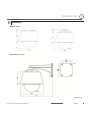
¨ Specifications
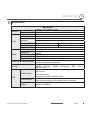
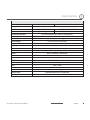
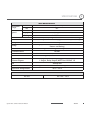
Specifications
Dimension
GSpeed Dome Camera Instruction Manual
70
74
6/74
Chapter 1.
INTRODUCTION
G
INTRODUCTION
1
Features
Powerful Zoom Camera & Setup Options
z Image Sensor : 1/4" Super HAD color CCD
z Zoom
: u27 Optical Zoom, u12 Digital Zoom
z Day & Night, Privacy Mask
z SNR (Super Noise Reduction) Function
z Various Focus Mode : Auto-Focus, Manual Focus, Semi-Auto Focus
z Various Setup Options in OSD Menu.
Powerful Pan/Tilt Functions
z MAX. 360q/sec High Speed Pan/Tilt Motion
z With the Vector Drive Technology, Pan/Tilt motions are accomplished along the
shortest path. As a result, the time to target view is remarkably short and the video on
the monitor is very natural in monitoring.
z With the Micro-Stepping Control Technology, the video looks very natural at high
zoom magnification during a jog operation on a controller since the camera can be
controlled by 0.05q/sec. Hence it is very easy to make the camera focus on desired
target views at high zoom magnification. Additionally it is easy to make the camera
focus on desired positions with zoom-proportional pan/tilt movement.
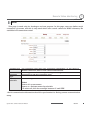
Preset, Pattern, Swing, Group, Privacy Mask and More…
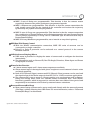
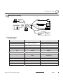
z MAX. 127 Presets are programmable and each preset can have its own parameter
values independently from the other presets.
For an example, refer to the below table.
Preset No.
White Balance
Auto Exposure
Preset 1
Case A
Case 3
“ENTRANCE”
Label
Preset 2
Case C
Case 5
“WAREHOUSE”
Preset 3
CaseV
Case 2
“OFFICE”
Case K
Case 9
Remarks
Preset 95
Reserved for OSD Menu
Preset 128
GSpeed Dome Camera Instruction Manual
“TERRACE”
8/74
G
INTRODUCTION
1
z MAX. 8 sets of Swing are programmable. This function is that the camera moves
repetitively between two preset positions at programmed speeds.
z MAX. 4 Patterns are programmable. This function is that the camera memorizes the
path (mostly curve path) by the joystick of the controller and revives the trajectory
operated by the joystick as closely as possible.
z MAX. 8 sets of Group are programmable. This function is that the camera memorizes
the combination of Presets, Pattern and/or Swings sequently and runs Presets, Pattern
and/or Swings repetitively. A Group can be combined upto 20 functions with any of
Preset/Pattern/Swing.
z MAX. 8 Privacy Masks are programmable, not to intrude on any other’s privacy.
PTZ(Pan/Tilt/Zoom) Control
z With the RS-485 communication connection, MAX. 255 units of cameras can be
connected to a single controller.
z Pelco-D or Pelco-P protocols can be selected as a control protocol in the current
firmware version.
OSD(On Screen Display) Menu
z OSD menu is provided to display the status of camera and to configure the functions
interactively.
z The information such as Camera ID, Pan/Tilt Angle, Direction, Alarm Input and Preset
is displayed on screen.
Alarm In/Out Function
z 3 alarm sensor inputs and 1 alarm sensor outputs are available.
z Alarm sensor input is decoupled with photo-couplers to avoid external electric noise
and shock perfectly.
z Both of N.O.(Normal Open) sensors and N.C.(Normal Close) sensors can be used and
the signal range of the Alarm output is from DC 5.0V to 12.0V for various applications.
z The camera can be set to move to a Preset position or to run functions such as Pattern,
Swing and Group when there are external sensor activations. Also “Post Alarm”
function is possible, which is supposed to activate after user-defined time period and
sequentially in succession to the action by external sensor activations.
Reserved Presets(Hot Keys)
z Most camera setup options can be set up easily and directly with the reserved presets
(Hot Keys), without entering into OSD menu. For more information, refer to “Reserved
Presets(Hot Keys)” in this manual.
GSpeed Dome Camera Instruction Manual
9/74
G
INTRODUCTION
1
Perfect Outdoor Environment Compatibility and Easy Installation
z The fans and heaters are built-in in the camera for cold and hot temperature
environment. Also idealistic mechanical design protects the camera from water and
dust. (IP67 when installed properly with wall mount bracket only / Only for outdoor
models)
z It is easy to install and repair the camera.
Audio
z Various Transmission Mode : Unidirectional Mode (IP-server to Client PC ),
Bi-directional Mode
Video
z High-Quality Compression Algorithm, H.264
z Compression into Various Resolution : CIF, Half-D1, D1
z Wide Range of Video Transmission Rate : 32kbps ~ 4Mbps
z Various Transmission Mode : CBR, VBR
z Motion Detection
Network
z
z
z
z
Static IP and Dynamic IP(DHCP, PPPoE) Support
One to One Connection and One to Multiple Connection
Multi-Casting
Automatic Transmission Rate Control by Network Condition
User Interface
z System Status Display with OSD(On Screen Display)
z System Configuration via Internet Explorer
Reliability
z Reliable Embedded System
z System Recovery with Dual Watch-Dog Function
GSpeed Dome Camera Instruction Manual
10/74
G
INTRODUCTION
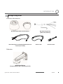
Package Component
Product & Accessories
z Main Body & Surface Mount Bracket
z Accessories for The Models with Alarm In/Out
Function [I/O Cable]
z Default Accessories
[Main Cable,Wrench]
z Lan Cable
z Audio Cable
Brackets
zWall Mount Bracket
[Screws : Machine M5u15,Hex Lag #14u50]
GSpeed Dome Camera Instruction Manual
11/74
1
G
INTRODUCTION
1
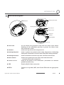
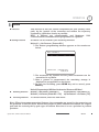
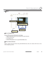
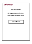
Main Part Description
Mounting Sc rew Hole
DIP Switch
Mounting Sa fety Wire
Main Conector
Sensor I/O Port
Audio Port
LAN Port
Mounting Hook
Dome Cover
z Dome Cover
Do not detach the protection vinyl from the dome cover before
finishing all the installation process to protect the dome cover
from scratches or dust.
z DIP Switch
Used to set up camera IDs and protocols.
z Mounting SafetyWire
Used to protect the product from being dropped by connecting
safety wire of bracket to hook of main body when being installed.
z Mounting Screw Hole
Used to assemble the main body with a bracket with screws.
z Main Connector
Used for the power wire, the video cable and the RS-485
communication cable connection.
z Sensor I/O Port
Used for the sensor in/out connection. (The sensor I/O function
possible models only)
z LAN
Used for RJ-45 Cable connection.
z AUDIO
Connect to a speaker, MIC, and Ground Wire with an appropriate
wire.
GSpeed Dome Camera Instruction Manual
12/74
Chapter 2.
INSTALLATION
G
INSTALLATION
2
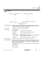
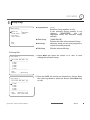
DIP Switch Setup
Before installing the camera, set up the DIP switch to configure the camera ID and the
communication protocol.
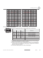
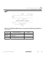
Camera ID Setup
z The ID number of camera is set using a binary number.
Examples shown below.
z The range of ID is 1~255. UDo not use 0 as camera IDU.
Factory default of Camera ID is 1.
z If you want to control a certain camera, you must match the
camera ID with Cam ID setting of DVR or Controller.
ON ON
1
2
3
4
5
6
7
8
Pin
1
2
3
4
5
6
7
8
Pin
1
2
3
4
5
6
7
8
ID
1
2
4
8
16
32
64
128
ID
1
2
4
8
16
32
64
128
1
on
off
off
off
off
off
off
off
11
on
on
off
on
off
off
off
off
2
off
on
off
off
off
off
off
off
12
off
off
on
on
off
off
off
off
3
on
on
off
off
off
off
off
off
13
on
off
on
on
off
off
off
off
4
off
off
on
off
off
off
off
off
14
off
on
on
on
off
off
off
off
5
on
off
on
off
off
off
off
off
15
on
on
on
on
off
off
off
Off
6
off
on
on
off
off
off
off
off
16
off
off
off
off
on
off
off
off
7
on
on
on
off
off
off
off
off
17
on
off
off
off
on
off
off
off
8
off
off
off
on
off
off
off
off
18
off
on
off
off
on
off
off
off
9
on
off
off
on
off
off
off
off
19
on
on
off
Off
on
off
off
off
10
off
on
off
on
off
off
off
off
20
off
off
on
off
on
off
off
off
GSpeed Dome Camera Instruction Manual
14/74
G
INSTALLATION
Pin
1
2
3
4
5
6
7
8
Pin
1
2
3
4
5
6
7
8
ID
1
2
4
8
16
32
64
128
ID
1
2
4
8
16
32
64
128
21
on
off
on
off
on
off
off
off
31
on
on
on
on
on
off
off
off
22
off
on
on
off
on
off
off
off
32
off
off
off
off
off
on
off
off
23
on
on
on
off
on
off
off
off
33
on
off
off
off
off
on
off
off
24
off
off
off
on
on
off
off
off
34
off
on
off
off
off
on
off
off
25
on
off
off
on
on
off
off
off
35
on
on
off
off
off
on
off
Off
26
off
on
off
on
on
off
off
off
36
off
off
on
off
Off
on
off
off
27
on
on
off
on
on
off
off
off
37
on
off
on
off
Off
on
off
off
28
off
off
on
on
on
off
off
off
38
off
on
on
off
Off
on
off
off
29
on
off
on
on
on
off
off
off
39
on
on
on
off
Off
on
off
off
30
off
on
on
on
on
off
off
off
40
off
off
off
on
Off
on
off
off
2
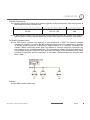
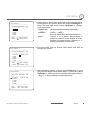
Communication Protocol Setup
z Select an appropriate Protocol with the DIP switch combination.
ON ON
1
Switch Mode
2
3
4
P0
(Pin 1)
P1
(Pin 2)
P2
(Pin 3)
Protocol
OFF
OFF
OFF
PELCO-D, 2400 bps
ON
OFF
OFF
PELCO-D, 9600 bps
OFF
ON
OFF
PELCO-P, 4800 bps
ON
OFF
PELCO-P, 9600 bps
ON
Others
Reserved
z Match the camera protocol with the camera protocol in the setting of
your DVR or controller to control the camera.G
z Adjust the DIP switch after turning off the camera. If you changed the
camera protocol by changing the DIP S/W, the change will be effective
after you reboot the camera.
z The factory default protocol is “Pelco-D, 2400 bps”.
GSpeed Dome Camera Instruction Manual
15/74
G
INSTALLATION
2
Terminal Resistor Setup
The terminal resistor is used for the following cases.
z Case 1 : In case that the control cable length between a camera and
a controller is relatively very long (1:1 Connection)
If the communication cable length is very long, the electrical signal will
bound in the terminal point. This reflected signal causes distortion of
original signal. Accordingly, the camera can be out of control. In this
case, the terminal resistor of both sides i.e. the camera and the
controller must be set to ‘ON’ state.
z Case 2 : In case that multiple cameras are connected to a
controller.
Due to similar reasons with the case 1, the terminal resister of the
controller and the last camera must be set to ‘ON’ state. The last camera
means the camera farthest in cable length from the controller. Do not
turn on the terminal resistor of all the cameras on the same
communication cable. G
GSpeed Dome Camera Instruction Manual
16/74
G
INSTALLATION
2
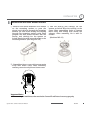
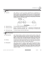
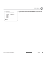
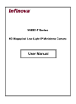
Installation with Wall Mount Bracket
ྙ Make a hole whose diameter is 30~40mm ྚ Pull the wire(s) and cable(s) for the
on the mounting surface to pass the
system as below. Wire the cable(s) to the
wire(s) and cable(s) through the mounting
ports. After assembling hook of camera
surface. (In case of the wiring and cabling
main body with safety wire inside the
through the mounting surface only) Then
adaptor. After assembly, fix it with 3r
prepare the wall mount bracket. Pull the
screws.
wire(s) and cable(s) for the system as
(Machine M5u15)
below. Attach the wall mount bracket to the
mounting surface. (Hex Lag #14u50)
ྛ Assembles dome cover with screws main
body with dome cover. After assembly,
remove protection vinyl from dome cover.
Important Notice
z Before starting the installation,make sure that the Camera ID and Protocol are set up properly.
GSpeed Dome Camera Instruction Manual
17/74
G
INSTALLATION
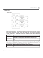
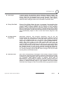
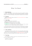
Wiring and Cabling
POWER
INTERNET
BROWSER
LAN CABLE
MIC SPEAKER
AUDIO
CABLE
BNC
MAIN CABLE
MONITOR
RS-485
I/O CABLE
CONT ROLLER / DVR
SENSOR I/O
IR
SENSOR
Port Description
z Main Cable
Port Pin Number (RJ45)
1
2,4
5
3
7
6,8
z I/O Cable
Port Pin Number (RJ25)
1
2
3
4
5
6
GSpeed Dome Camera Instruction Manual
Connector / Wire Color
DOOR
SWITCH
Red
Yellow
Orange
White
Signal
Video +
Video RS-485 +
RS-485 Power +
Power Wire Color
Blue
Yellow
Green
Red
Black
White
Signal
IN COM +
IN 1 IN 2 IN 3 OUT A
OUT B
BNC Connector
18/74
2
G
INSTALLATION
2
Power Description
z Carefully check the voltage and current capacity of the rated power. The rated power is
indicated in the back of main unit.
Rated Power
InputVoltage Range
Current Consumption
DC12V
DC 11V ~18V
3.0A
z In case that the length of the power wire is very long, there may be voltage drop and the
syatem may not work properly. Make the length of the power wire as short as possible.
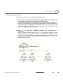
RS-485 Communication
z For PTZ control, connect the cable(s) to your keyboard or DVR. To connect multiple
cameras to a single controller, RS-485 communication should be connected in parallel
as shown below. If you are connecting a single camera to a controller, terminate the
camera. When connecting more than one camera to a single controller, terminate the
last camera on the communication line. The last camera means the camera farthest in
cable length from the controller.GNote that the total length of the communication cable
between a controller and the camera(s) on the same communication line must be less
than 1.2Km.G
G
Video
z Use BNC coaxial cable only.
GSpeed Dome Camera Instruction Manual
19/74
G
INSTALLATION
2
Alarm Input
G
z Sensor Input
G
G
G
G
G
G
G
G
G
G
G
G
G
G
G
G
G
G
Before connecting sensors, check driving voltages and output signal types of the sensors.
Since output signal types of the sensors are divided into Open Collector type and
Voltage Output type in general, the wiring must be done properly after considering
those types.
Signal
Description
IN COM+
The electric power source to drive input circuit. Connect the (+) wire of electric
power source to drive the Sensors to this port as shown in the above circuit.
IN1 -,IN2 -,IN3 -
Connect the outputs of sensors to each port as shown in the above
circuit.
If you want to use Alarm Input, the types of sensors must be selected in OSD menu. The
sensor types are divided into Normal Open and Normal Close. If wrong sensor types are
selected, alarms should be activated reversely to sensor inputs.
~ Normal Open
Output Voltage is high state when sensor is activated
~ Normal Close
Output Voltage is high state when sensor is not activated
GSpeed Dome Camera Instruction Manual
20/74
G
INSTALLATION
Relay Output
The maximum loads are as follows.
Power Type
Maximum Load
GSpeed Dome Camera Instruction Manual
DC Power
MAX. DC 24V, 1A
21/74
2
Chapter 3.
OPERATION
G
OPERATION
3
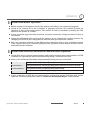
Check Points before Operation
z Before turning on the system, check if the wire(s) and cable(s) are connected properly.
z Check if the camera ID on the controller is properly selected. The camera ID must be
identical to that of the target camera. The camera ID can be checked by reading the DIP
switch of the camera or on OSD.
z If your controller supports multi-protocols, the protocol must be changed to match to that of
the camera.
z Adjust the DIP switch after turning off the camera. If you changed the camera protocol by
changing the DIP S/W, the change will be effective after you reboot the camera.
z Since the operation method can be different by controllers, refer to your controller manual
if the camera can not be controlled properly. The operation of this manual is based on the
standard Pelco® Controller.
Check Points for Preset and Pattern Function before Operation
z Check fully how to operate preset function and pattern function with your controller or DVR
in advance to operate the camera functions when using a controller or a DVR.
z Refer to the following table when using standard Pelco® protocol controllers.
< Go Preset >
Input [Preset Number] and press [Preset] button shortly.
< Set Preset >
Input [Preset Number] and keep pressing [Preset] button for more than 2 seconds.
< Run Pattern >
Input [Pattern Number] and press [Pattern] button shortly.
< Set Pattern >
Input [Pattern Number] and keep pressing [Pattern] button for more than 2 seconds.
z If your controller or DVR has no pattern button or function, use the Hot Keys with preset
numbers. For more information, refer to “Reserved Presets(Hot Keys)” in this manual.
GSpeed Dome Camera Instruction Manual
23/74
G
OPERATION
3
OSD Menu
z Function
With OSD menu, the system can be properly configured for each
application.
z Entering into OSD
Go Preset [95]
Reserved Presets (Hot Keys)
z Description
Some Preset numbers are reserved to change some parameters without entering into
OSD menu.
z Hot Keys
Go Preset [95]
: Entering into OSD menu
Go Preset [131~134] :Running Pattern Function 1 ~ 4
Go Preset [141~148] :Running Swing Function 1 ~ 8
Go Preset [151~158] :Running Group Function 1 ~ 8
Go Preset [161]
:Turning off Relay Output
Set Preset [161]
:Turning on Relay Output
Go Preset [167]
: Setting Zoom Proportional Function to ON
Set Preset [167]
: Setting Zoom Proportional Function to OFF
Go Preset [170]
: Setting Camera BLC/WDR Mode to OFF
Go Preset [171]
: Setting Camera BLC/WDR Mode to ON
Go Preset [174]
: Setting Camera Focus Mode to AUTO
Go Preset [175]
: Setting Camera Focus Mode to Manual
Go Preset [176]
: Setting Camera Focus Mode to SEMI-AUTO
Go Preset [177]
: Setting Day & Night Mode to AUTO
Go Preset [178]
: Setting Day & Night Mode to NIGHT
Go Preset [179]
: Setting Day & Night Mode to DAY
Go Preset [190]
: Setting OSD Display Mode to AUTO (Except Privacy Mask)
Go Preset [191]
: Setting OSD Display Mode to OFF (Except Privacy Mask)
Go Preset [192]
: Setting OSD Display Mode to ON (Except Privacy Mask)
Go Preset [193]
: Setting all Privacy Mask Display to OFF
Go Preset [194]
: Setting all Privacy Mask Display to ON
GSpeed Dome Camera Instruction Manual
24/74
G
OPERATION
3
Preset
z Function
MAX. 127 positions are programmable. The Preset number can be
assigned from 1 to 128 except 95. Preset 95 is reserved for entering
into OSD menu. Camera parameters such as White Balance, Auto
Exposure and others can be set up independently and each preset
can have its own parameter values independently from the other
persets. When setting up presets with a controller, Label should be
blank and "Camera Adjust" should be set to "GLOBAL" as the default.
To change the parameters, enter into OSD menu.
z Setting Presets
Set Preset [1~128]
z Running Presets
Go Preset [1~128]
z Deleting Presets
To delete Presets, enter into OSD menu.
Swing
z Function
This function is that the camera moves repetitively between two
preset positions at programmed speeds. When a swing function runs,
the camera moves from the preset assigned as the 1st point to the
preset assigned as the 2nd point in CW(Clockwise) direction. Then
the camera moves from the preset assigned as the 2nd point to the
preset assigned as the 1st point in CCW(Counterclockwise)
direction.
In case that the preset assigned as the 1st point and the preset
assigned as the 2nd point are same, the camera turns on its axis by
360q in CW(Clockwise) direction and then it turns back on its axis by
360q in CCW(Counterclockwise) direction. The Swing speed is
defined from 1q/sec to 180q/sec.
z Setting Swings
To set Swing, enter into OSD menu.
z Running Swings
Method 1) <Run Pattern> [Swing NO. + 10]
Method 2) <Go Preset> [Swing NO. + 140]
z Deleting Swings
To delete Swings, enter into OSD menu.
GSpeed Dome Camera Instruction Manual
ex) Run Swing 3 : <Run Pattern> [13]
ex) Run Swing 3 : <Go Preset> [143]
25/74
G
OPERATION
3
Pattern
z Function
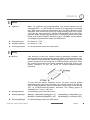
This function is that the camera memorizes the path (mostly curve
path) by the joystick of the controller and revives the trajectory
operated by joystick as closely as possible.
MAX. 4 Patterns are programmable and Maximum 1200
communication commands can be programmed in a pattern.
z Setting Patterns
A Pattern can be created by the following methods.
Method 1) <Set Pattern> [Pattern NO.]
{ The Pattern programming window appears on the monitor as
below.
EDIT PATTERN 1
[NEAR:SAVE
/FAR:DELETE]
0/0/x1/N
{ The movement by Joystick and the preset movement can be
memorized in a pattern.
{ After a pattern is programmed, the remaining storage is
displayed in progress bar on the screen.
{ To save the recording, press NEAR key and to cancel, press
FAR key.
Method 2) Programming in OSD Menu :See the section“How to use OSD Menu”.
z Running Patterns
Method 1) <Run Pattern> [Pattern NO.]
Method 2) <Go Preset> [Pattern NO. + 130]
z Deleting Patterns
To delete Patterns, enter into OSD menu.
ex) Run Pattern 2 : <Run Pattern> [2]
ex) Run Pattern 2 : <Go Preset> [132]
Note) When the system memorizes Patterns, the commands are stored in the momories, not
the positions of Pan/Tilt/Zoom. Hence there might be small differences between the original
path and the revived path by path type of Patterns. Note that it is not a problem in position
precision.
GSpeed Dome Camera Instruction Manual
26/74
G
OPERATION
3
Group
z Function
This function is that the camera memorizes the combination of
Presets, Pattern and/or Swings sequently and runs Presets, Pattern
and/or Swings repetitively. MAX. 8 sets of Group are programmable.
Each group can have MAX. 20 actions which are the combination of
Preset, Pattern and Swing. Preset speed can be set up and the repeat
number of Pattern & Swing can be set up in Group setup. Dwell time
between actions can be set up also.
z Setting Groups
To set Groups, enter into OSD menu.
z Running Groups
Method 1) <Run Pattern> [Group NO. + 20]
Method 2) <Go Preset> [Group NO. + 150]
z Deleting Groups
To delete Groups, enter into OSD menu.
ex) Run Group 7 : <Run Pattern> [27]
ex) Run Group 7 : <Go Preset> [157]
Other Functions
z Power Up Action
This setting defines a specific activity (Preset, Pattern, Swing and
Group) to be performed in the event that the power to the camera is
cycled. This function enables the user to resume, after turning on
power, the last action being executed before turning off the power.
Most of actions such as Preset, Pattern, Swing and Group are
available for this function but Jog actions are not available to resume.
z Auto Flip
In case that tilt angle arrives at the top of tilt orbit(90°), zoom module
camera turns on its axis by 180° at the top of tilt orbit and moves to
opposite tilt direction (180°) to keep tracing targets.
z Parking Action
This feature allows the camera to begin a specified operation after a
programmed time of inactivity. This function makes the camera
automatically run a pre-defined action if there is no command from
controller for a pre-defined time period. “Wait Time” means how
long a camera should wait for from the previous-last (most recent)
command before running the pre-defined action. It can be set to 1
second ~ 3 hours.
G
GSpeed Dome Camera Instruction Manual
27/74
G
OPERATION
3
G
z Alarm Input
3 Alarm Inputs are available. When external sensors activate, the
camera runs pre-defined actions such as Preset, Pattern, Swing and
Group. After the pre-defined time period passed, “Post Alarm”
activates, which is pre-defined. Note that only the latest alarm input is
effective when multiple sensors are activated at the same time.
z Privacy Zone Mask
Privacy Zone Mask allows the user to program 8 rectangulars that
can not be viewed by the operator of the system. To protect others’
privacy, MAX. 8 Privacy Masks can be created on the arbitrary
position to hide objects such as windows, shops or private house.
With the Spherical Coordinates system, powerful Privacy Zone Mask
function is possible. A mask area will move with pan and tilt functions
and automatically adjust in size as the lens zooms telephoto and
wide.
z GLOBAL/LOCAL
Image Setup
WB(White Balance) and AE(Auto Exposure) can be set up
independently for each preset. There are 2 modes, "Global" mode &
"Local" mode. The Global mode is that WB and/or AE are/is set up
totally and simultaneously for all presets. The Global parameter
setup such as WB and AE can be done in "ZOOM CAMERA SETUP"
menu. The Local mode is that WB and/or AE are/is set up
independently or separately for each preset. The Local parameter
setup for WB and AE can be done in each preset setup menu. Each
Local parameter such as WB and AE activates correspondingly when
the camera arrives at each preset position. During jog operation,
Global WB/AE value should be applied. All Local WB/AE values do
not change although Global WB/AE value changes. The Local mode
has the prior to the Global mode.
z Semi-Auto Focus
This mode automatically exchanges focus modes between Manual
Focus mode and Auto Focus mode by operation. Manual Focus mode
activates in preset operation and Auto Focus mode activates during
jog operation. With Manual mode at presets, Focus data is
memorized in each preset in advance and the camera calls focus
data in correspondence with presets as soon as the camera arrives at
presets. It should shorten time to get focuses. The focus mode
automatically changes to Auto Focus mode when jog operation starts.
GSpeed Dome Camera Instruction Manual
28/74
G
OPERATION
3
OSD Display
Preset LabelG
Camera IDG
LABEL12345
PRESET1G
I:-2- O:1G
15/4/x1/N
CAM 1
Action TitleG
Alarm InformationG
P/T/Z InformationG
z P/T/Z Information
Displays the amount of pan from zero degree vertical, the amount of
tilt from zero degree horizontal and current compass direction. Also
identifies the amount of the zoom magnification.
z Camera ID
Displays the selected Camera ID (Address).
z Action Title
Identfies Actions
"SET PRESET xxx"
When Preset xxx is memorized.
"PRESET xxx"
When the camera reaches Preset xxx.
"PATTERN x"
When Pattern x is in action.
"SWGu/PRESET xxx"
When Swing x is in action. Displays both of Swing
number and Preset number.
"UNDEFINED"
When a undefined function is called to run
z Preset Label
Displays preset labels when the camera arrives at presets.
z Alarm Information
Displays activated alarms. This information shows current state of
Alarm Inputs and Relay Outputs. If an Input point is ON state, it will
show a number corresponding to each point. If an Input point is OFF
state, ٻڂڈڂwill be displayed.
Example) The point 2 & 3 of inputs are ON and Output is ON, OSD will
show as below.
I:-23 O:1
GSpeed Dome Camera Instruction Manual
29/74
Chapter 4.
OSD MENU
G
OSD MENU
4
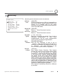
Quick Programming Guide
z
z
z
z
z
z
The menu items with < > always have sub-menus.
To go to submenus or make the cursor move to the right, press NEAR key.
To go to the previous-upper level menus, press FAR key.
To make a selection, press NEAR key
To cancel a selection, press FAR key
To move the cursor in the menu, use the joystick to the Up/Down direction or Left/Right
direction.
z To change a value of an item, use Up/Down of the joystick in the controller.
z To save changes, press NEAR key.
z To cancel changes, press FAR key.
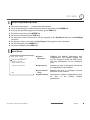
Main Menu
z System
Information
Displays the system information and
configuration. The system setting can
not be changed using the OSD menu
and the information is for reference
only.
<SYSTEM INITIALIZE>
z Display Setup
Enables the user to program how labels
are displayed on the monitor.
EXIT
z Dome Camera
Setup
Enables the user to configure various
functions of the camera.
z System Initialize
Initializes all system configurations and
all data to the factory default
parameters.
SPEED DOME CAMERA
-----------------------<SYSTEM INFORMATION>
<DISPLAY SETUP>
<DOME CAMERA SETUP>
GSpeed Dome Camera Instruction Manual
31/74
G
OSD MENU
4
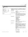
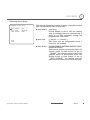
Display Setup
DISPLAY SETUP
-----------------------CAMERA ID
ON
PTZ INFORMATION
AUTO
ACTION TITLE
AUTO
PRESET LABEL
AUTO
ALARM I/O
AUTO
<SET NORTH DIRECTION>
<PRIVACY ZONE>
BACK
EXIT
Display setup allows you to program how labels are
displayed on the monitor. In case of AUTO, the labels are
displayed on the monitor when there are any changes in
parameters.
z Camera ID
[ON/OFF]
Displays the
(Address).
selected
Camera
z PTZ Information
[ON/OFF/AUTO]
Displays the amount of pan from zero
degree vertical, the amount of tilt from
zero degree horizontal and current
compass direction. Also identifies the
amount of the zoom magnification.
z Action Title
[ON/OFF/AUTO]
Identfies Actions.
"SET PRESET xxx"
"PRESET xxx"
"PATTERN x"
"SWG/PRESET xxx"
"UNDEFINED"
z Preset Label
[ON/OFF/AUTO]
Displays the preset labels when the
camera arrives at presets.
z Alarm I/O
[ON/OFF/AUTO]
Displays the activated alarms. This
information shows the current state of
Alarm Inputs and Relay Outputs. If an
Input point is ON state, it will show a
number corresponding to each point. If
an Input point is OFF state, ٻڂڈڂwill be
displayed.
Example) The point 2 & 3 of inputs are
ON and Output is ON, OSD will show as
below.
I:-23 O:1
GSpeed Dome Camera Instruction Manual
ID
32/74
G
OSD MENU
4
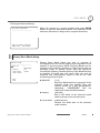
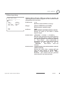
Compass Direction Setup
Move the camera to a target position and press NEAR
button to save the direction as North. The direction is the
reference direction to assign other compass directions.
SET NORTH DIRECTION
------------------------
G
MOVE TO TARGET POSITION
[NEAR:SAVE /FAR:CANCEL
Privacy Zone Mask Setup
Privacy Zone Mask allows the user to program 8
rectangulars that can not be viewed by the operator of the
system. To protect privacy, MAX. 8 Privacy Masks can be
created on the arbitrary position to hide objects such as
windows, shops or private house. With the Spherical
Coordinates system, powerful Privacy Zone Mask function
is possible. A mask area will move with pan and tilt
functions and automatically adjust in size as the lens
zooms telephoto and wide.
PRIVACY ZONE
-----------------------MASK NO
1
UNDEFINED
DISPLAY
OFF
CLEAR MASK
CANCEL
<EDIT MASK>
BACK
EXIT
z Mask NO
[1~8]
Selects a Mask number to program. If the
selected mask has already data, the
camera moves as it was programmed.
Otherwise, “UNDEFINED” will be
displayed under the Mask number.
z Display
[ON/OFF]
Sets if the mask of the selected mask
number shows or not on the screen.
z Clear Mask
[CANCEL/OK]
Deletes the mask data of the selected
mask number.
G
GSpeed Dome Camera Instruction Manual
33/74
G
OSD MENU
4
Privacy Zone Mask Area Setup
Move your camera to an area to mask. Then a mask and the
menu to adjust the mask size will be displayed.
EDIT MASK 1
------------------------
G
MOVE TO TARGET POSITION
[NEAR:SELECT/FAR:CANCEL]
Privacy Zone Mask Size Setup
EDIT MASK 1G
------------------------G
Adjusts the mask size. Use the joystick or the arrow buttons
of your controller to adjust mask size.
z (Left/Right)
Adjusts the mask width.
z (Up/Down)
Adjusts the mask height.
G
[ :ADJUST MASK WIDTH]G
[ :ADJUST MASK HEIGHT]G
[NEAR:SAVE
/FAR:CANCEL]G
GSpeed Dome Camera Instruction Manual
34/74
G
OSD MENU
4
Camera Setup
ZOOM CAMERA SETUP
-----------------------FOCUS MODE
SEMIAUTO
DIGITAL ZOOM
ON
IMAGE FLIP
OFF
SHARPNESS
16
STABILIZATION OFF
<WHITE BALANCE SETUP>
<AUTO EXPOSURE SETUP>
Sets the general functions of zoom camera module.
z Focus Mode
BACK
EXIT
[AUTO/MANUAL/SEMIAUTO]
Sets camera Focus mode.
{ SEMIAUTO Mode
This mode automatically exchanges focus
modes between Manual Focus mode and
Auto Focus mode by operation. Manual
Focus mode activates in preset operation
and Auto Focus mode activates during
jog operation. With Manual mode at
presets, Focus data is memorized in each
preset in advance and the camera calls
focus data in correspondence with
presets as soon as camera arrives at
presets. It should shorten time to get
focuses. Focus mode automatically
changes to Auto Focus mode when jog
operation starts.
z Digital Zoom [ON/OFF]
Sets the digital zoom functions to
ON/OFF. If this is set to OFF, the optical
zoom function runs but the zoom function
stops at the end of optical zoom
magnification.
z Image Flip
[ON/OFF]
Sets System Image Flip Function to
ON/OFF. When this function is set to ON,
flipped images always come out. When
the camera is installed as Desktop type,
set to ON to get proper images.
z Sharpness
[0-32]
Sets image
pictures.
sharpness
to
enhance
G
GSpeed Dome Camera Instruction Manual
35/74
G
OSD MENU
4
z Stabilization
[ON/OFF]
Compensates image vibrations by wind
or others. The images with vibrations are
compensated by Digital Zoom function
and the image resolution with this
function should be lower than normal
image resolution when this function is
turned on. Also this function may not
work properly in the following cases.
Dark scene or Low contrast scene
High frequency vibration
During Pan/Tilt/Zoom/Focus moving
During Iris/Shutter/Gain moving
z WB Mode
[AUTO/MANUAL]
Retains color balance over a color
temperature range. In auto mode, this
feature automatically processes the
viewed image. In Manual mode, Red and
Blue level can be set up manually.
z Red Adjust
[0-255]
Adjusts the picture output in the red
range.
z Blue Adjust
[0-255]
Adjusts the picture output in the blue
range.
White Balance Setup
WB SETUP - GLOBAL
------------------------G
WB MODE
AUTOG
RED ADJUST
---G
BLUE ADJUST
---G
BACK
EXIT
GSpeed Dome Camera Instruction Manual
36/74
G
OSD MENU
4
Auto Exposure Setup
AE SETUP - GLOBAL
-----------------------BACKLIGHT
OFF
DAY/NIGHT
AUTO
BRIGHTNESS
50
IRIS
AUTO
SHUTTER
ESC
AGC
MIDDLE
SSNR
MIDDLE
SENS-UP
<AUTO>
BACK
EXIT
z Backlight
[OFF/WDR/BLC/HLC] or [OFF/BLC/HLC]
Sets Backlight Compensation. If a bright
backlight is present, the subjects in the
picture may appear dark or as a
silhouette.
Backlight
compensation
enhances objects in the center of the
picture. The camera uses the center of the
picture to adjust the iris. If there is a
bright light source outside of this area, it
will wash out to white. The camera will
adjust the iris so that the object in the
sensitive area is properly exposed.
Some modles has WDR(Wide Dynamic
Range) function, which are better function
than BLC. HLC(High Light Compensation)
function removes the high light in a
limited environment such as parking
garage.
z Day/Night
[AUTO/DAY/NIGHT]
Sets Day&Night mode.
z Brightness
[0~100]
Adjusts the brightness of the images. Iris,
The Shutter Speed and Gain are adjusted
automatically in correspondence with
each numeric value.
z IRIS
[AUTO/MANUAL(F1.6~F28)]
Sets Iris to operate automatically or at a
user-defined level. If Iris is set to Auto,
Iris has higher priority in adjusting AE
and Shutter Speed is fixed. Auto iris is the
lens function that automatically opens
closes the iris in response to changing
light conditions.
If Iris is set to Manual, Iris is fixed and Iris
has lower priority in adjusting AE, in
comparison with others.
G
GSpeed Dome Camera Instruction Manual
37/74
G
OSD MENU
z Shutter Speed
[ESC/A.Flicker/Manual(u256~1/120000 sec)]
Sets Shutter Speed. Shutter Speed is the duration
of the electronic shutter. If Iris is set to Manual
and Shutter Speed is set to ESC, Shutter Speed
has higher priority. If Shutter Speed is set to
A.Flicker, to remove Flicker, Shutter Speed
should be set to 1/100 sec. for NTSC and 1/120
for PAL.
z AGC
[OFF/LOW/MIDDLE/HIGH/MANUAL(5~41dB)]
Sets AGC. This setting enhances image
brightness automatically in case that luminance
level of image signal is too low.
z SSNR
[OFF/LOW/MIDDLE/HIGH]
Sets SSNR. This setting enhances the images by
deducting noises when the gain level of the
mages is too high.
z SENS-UP
[AUTO(2~256)/OFF]
Sets SENS-UP. This setting activates Slow Shutter
function when luminance of image (signal) is too
dark.
It is possible to set up the maximum number of
frames piled up one on another by Slow Shutter
function.
G
GSpeed Dome Camera Instruction Manual
4
38/74
G
OSD MENU
4
Motion Setup
MOTION SETUP
-----------------------MOTION LOCK
OFF
PWR UP ACTION
ON
AUTO FLIP
ON
JOG MAX SPEED
120/SEC
JOG DIRECTION
INVERSE
FRZ IN PRESET
OFF
<PARKING ACTION SETUP>
<ALARM INPUT SETUP>
BACK
EXIT
GSpeed Dome Camera Instruction Manual
Sets the general functions of Pan/Tilt motions.
z Motion
Lock
[ON/OFF]
If Motion Lock is set to ON, it is impossible to
set up and delete Preset, Swing, Pattern and
Group. It is possible only to run those
functions. To set up and delete those functions,
enter into OSD menu.
z Power Up [ON/OFF]
Action
Refer to Other Functions" section.
z Auto Flip
[ON/OFF]
Refer to Other Functions" section.
z Jog Max
Speed
[1q/sec ~360q/sec]
Sets the maximum jog speed. Jog speed is
inversely
proportional
to
the
zoom
magnifications. As the zoom magnification
goes up, the pan/tilt speed goes down.
z Jog
Direction
[INVERSE/NORMAL]
Sets the Jog Direction. If this is set to
ೢInverseೣ, the view direction in the screen is
same as the direction of joystick. If this is set
to ೢNormalೣ, the view direction in the
screen is the reverse dirction of joystick.
z Freeze
in Preset
[ON/OFF]
Sets Frame Freeze Function. This feature
freezes the scene on the monitor when going
to a preset. At the start point of a preset
movement, a camera starts freezing the image
of the start point. Camera keeps displaying
the image of the start point during preset
movement and does not display the images
which camera gets during preset movement.
As soon as camera stops at preset end point,
camera starts displaying live images which it
gets at the end preset point. This feature also
reduces bandwidth when working with digital
systems or digital network systems.
This function availability should be different
by models.
39/74
G
OSD MENU
4
Parking Action Setup
PARKING ACTION SETUP
-----------------------PARK ENABLE
OFF
WAIT TIME
00:10:00
PARK ACTION
HOME
BACK
EXIT
GSpeed Dome Camera Instruction Manual
This feature allows the camera to begin a specified action
after a programmed time of inactivity.
z Park Enable [ON/OFF]
If Park Enable is set to ON, the camera
runs an assigned function automatically if
there is no PTZ command during the
programmed "Wait Time".
z Wait Time
[1~59 sec. / 1~180 min.]
Wait Time can be programmed from 1
second to 180 minutes.
z Park Action
[HOME/PRESET/PATTERN/SWING/GROU
P/PREV ACTION]
This feature defines the activity when the
camera parks. If Park Action is set to
HOME, the camera moves to the home
position which is memorized when the
system boots. If Park Action is set to
PREV. ACTION, the camera runs the
previous action which it ran most recently.
40/74
G
OSD MENU
4
Alarm Input Setup
ALARM INPUT SETUP
-----------------------ALARM NO.
1
TYPE
ACTION
HOLD TIME
POST ACTION
N.OPEN
NOT USED
ENDLESS
HOME
BACK
EXIT
Defines Alarm Function. When an alarm is receive, an
input signal to the camera triggers the user-defined action
programmed for the alarm.
z Alarm No
[1~3]
Selects a sensor number to set up.
z Type
[Normal OPEN/Normal CLOSE]
Selects sensor operation type.
z Action
[NOT
USED/PRESET/PATTERN/SWING/GROUP]
Selects an action to run when a sensor
signal is input.
z Hold Time
[ENDLESS / 1~59 SEC. / 1~180 MIN.]
Sets the time period for the action which is
run by external sensor activation. After the
time period passes, the action pre-defined
in Post Action runs sequentially in
succession to the action by external sensor
activation. If this option is set to
ENDLESS, Post Action does not
activate.
z Post Action [HOME/PRESET/PATTERN/SWING/GROUP
/PREV ACTION]
Selects the action that a camera will run
after the time period inHOLD TIME
passes. If Post Action is set to PREV.
ACTION, the camera runs the previous
action which it ran most recently.
GSpeed Dome Camera Instruction Manual
41/74
G
OSD MENU
4
Preset Setup
PRESET SETUP
-----------------------PRESET NO.
1
CLR PRESET
<EDIT SCENE>
<EDIT LABEL>
RELAY OUT
CAM ADJUST
z Preset
Number
[1~128]
Selects a preset number to set up. If a
selected preset is already defined, the
camera moves to the pre-defined position
and preset parameters such as Label and
CAM Adjust show on the monitor. If a
selected
preset
is
not
defined,
“UNDEFINED” shows on the monitor.
z Clear
Preset
[CANCEL/OK]
Deletes the data of the selected Preset.
z Edit
Preset Scene
Re-defines the scene position of the
selected Preset.
z Edit
Preset Label
Edits the label of the selected Preset to
show on the monitor when the preset runs.
MAX. 10 alphanuberic characteristics are
allowed.
z Relay Out
Defines the relay output.
z CAM Adjust
[GLOBAL/LOCAL]
WB(White
Balance)
and
AE(Auto
Exposure) can be set up independently for
each preset. There are 2 modes, "Global"
mode & "Local" mode. The Global mode is
that WB and/or AE are/is set up totally and
simultaneously for all presets. The Global
parameter setup such as WB and AE can
be done in "ZOOM CAMERA SETUP" menu.
The Local mode is that WB and/or AE
are/is set up independently or separately
for each preset. The Local parameter setup
for WB and AE can be done in each preset
setup menu. Each Local parameter such as
WB and AE activates correspondingly
when the camera arrives at each preset
position. During jog operation, Global
WB/AE value should be applied. All Local
WB/AE values do not change although
Global WB/AE value changes. The Local
mode has the prior to the Global mode.
CANCEL
LABEL123
OFF
GLOBAL
BACK
EXIT
G
GSpeed Dome Camera Instruction Manual
42/74
G
OSD MENU
4
Preset Scene Setup
1 Use the Joystick to move the camera to a desired
ഗ
position.
EDIT SCENE - PRESET 1
------------------------
2 Save the preset position by pressing NEAR key.
ഗ
3 Press FAR key to cancel targeting the preset position.
ഗ
G
MOVE TO TARGET POSITION
[NEAR:SAVE /FAR:CANCEL]
Preset Label Setup
EDIT LABEL - PRESET 1G
------------------------G
[
]G
----------G
1234567890
OKG
ABCDEFGHIJ
CANCELG
KLMNOPQRSTG
UVWXYZabcdG
efghijklmnG
opqrstuvwxG
yz<>-/:.G
----------G
Edit the label of the selected preset to show on the
monitor when camera arrives at the preset. In the Edit
Label menu, the dark rectangular is the cursor. As soon as
finishing selecting an alphabet or a number, the cursor
moves to the next digit.
[
]
Current Cursor Position
ྙGWith Left/Right/Up/Down of the joystick, move to a
desired Alphabet or a desired number in the
Alphanumeric set. To select a desired Alphabet or a
desired number, press the NEAR key.
---------1234567890
ABCDEFGHIJ
KLMNOPQRST
UVWXYZabcd
efghijklmn
opqrstuvwx
yz<>-/:.
----------
Space Char. Back Space Char.
If you want to use a blank, select the double quotation
mark (" "). If you want to delete an Alphabet or a
number, use the back space character (" m").
ྚGIf you complete the Label editing, move the cursor to
"OK" and press the NEAR key to save the completed
label. To abort the current change, move the cursor to
"Cancel" and press the NEAR key.
GSpeed Dome Camera Instruction Manual
43/74
G
OSD MENU
4
Swing Setup
SWING SETUP
-----------------------SWING NO.
1
1ST POS.
NOT USED
2ND POS.
NOT USED
SWING SPEED
CLEAR SWING
RUN SWING
30/SEC
CANCEL
z Swing
Number
[1~8]
Selects a Swing number to edit. If the
selected Swing is not defined, "NOT USED"
is displayed in the 1st Position and the 2nd
Position.
z 1st Position
2nd Position
[PRESET 1~128]
Sets the 2 positions for a Swing function. If
the selected preset is not defined,
"UNDEFINED" is displayed as shown
below.
BACK
EXIT
SWING SETUPG
------------------------G
SWING NO.
1G
1ST POS.
PRESET5G
2ND POS.
NOT USEDG
UNDEFINEDG
When a swing function runs, the camera
moves from the preset assigned as the 1st
point to the preset assigned as the 2nd
point in CW(Clockwise) direction. Then
the camera moves from the preset
assigned as the 2nd point to the preset
assigned as the 1st point in CCW
(Counterclockwise) direction. In case that
the preset assigned as the 1st point and the
preset assigned as the 2nd point are same
or only 1 Preset position is assigned, the
camera turns on its axis by 360q in CW
direction and then it turns on its axis by
360q in CCW direction.
z Swing
Speed
[1q/sec. ~180q/sec.]
Defines Swing speed between the 2 Preset
positions from 1q/sec to 180q/sec
z Clear Swing
[CANCEL/OK]
Deletes the data of the selected Swing.ٻ
z Run Swing
Runs Swing for the test purposes to check
if it works properly.ٻ
G
GSpeed Dome Camera Instruction Manual
44/74
G
OSD MENU
4
Pattern Setup
PATTERN SETUP
-----------------------PATTERN NO.
1
UNDEFINED
CLR PATTERN
CANCEL
RUN PATTERN
<EDIT PATTERN>
BACK
EXIT
z Pattern Number
[1~4 ]
Selects a Pattern number to edit. If the
selected
pattern number is not
defined,
"UNDEFINED"
will
be
displayed under the selected pattern
number.
z Clear Pattern
[CANCEL/OK]
Deletes the data of the selected pattern.
z Run Pattern
Runs the Pattern for the test purposes to
check if it works properly.
z Edit Pattern
Edits the selected pattern.
Pattern Edit
EDIT PATTERN 1
------------------------
ྙGWith the Joystick of your controller, move the camera to
the start position with an appropriate zoom
magnafication. To start the pattern recording, press
NEAR key. To exit, press FAR key.
MOVE TO START POSITION
[NEAR:START /FAR:CANCEL]
EDIT PATTERN 1
[NEAR:SAVE
/FAR:DELETE]
0/0/x1/N
GSpeed Dome Camera Instruction Manual
ྚGMove camera with joystick of controller or run preset
function to memorize the path (mostly curve path) in the
selected pattern. The movement by Joystick and preset
movement will be memorized in a pattern. After a
pattern is programmed, the remaining storage is
displayed in progress bar on the screen.
ཝGTo save the data and exit, press NEAR key. To cancel
saving the data and delete the data, press FAR key.G
45/74
G
OSD MENU
4
Group Setup
GROUP SETUP
-----------------------GROUP NO.
1
UNDEFINED
CLEAR GROUP
CANCEL
RUN GROUP
<EDIT GROUP>
BACK
EXIT
z Group Number
[1~8]
Selects a Group number to edit.
If the selected Group number is not
defined,
"UNDEFINED"
will
be
displayed under the selected Group
number.
z Clear Group
[CANCEL/OK]
Deletes the data of the selected Group.
z Run Group
Runs the Group for the test purposes to
check if it works properly.
z Edit Group
Edit the selected Group.
Group Edit
EDIT GROUP 1
-----------------------NO ACTION ### DWELL OPT
-----------------------1 NONE
2 NONE
3 NONE
4 NONE
5 NONE
-----------------------SAVE
CANCEL
[NEAR:EDIT]
EDIT GROUP 1
-----------------------NO ACTION ### DWELL OPT
-----------------------1 NONE
2 NONE
3 NONE
4 NONE
5 NONE
-----------------------SAVE
[NEAR:EDIT ACT]
CANCEL [FAR :EDIT END]
GSpeed Dome Camera Instruction Manual
ྙGPress Near key when the cursor is at “NO” to start
editing the selected Group.
ྚGNote that MAX. 20 actions are allowed in a Group. Move
the cursor up/down to select an Action. Press Near key
to edit.
46/74
G
OSD MENU
EDIT GROUP 1
------------------------G
NO ACTION ### DWELL OPT
------------------------G
1 NONEG
2 NONEG
3 NONEG
4 NONEG
5 NONEG
------------------------G
SAVE
[ :MOVE CURSOR]G
CANCEL [ :CHANGE VAL.]
EDIT GROUP 1G
------------------------G
NO ACTION ### DWELL OPTG
------------------------G
1 PRESET
1 00:03 360
2 NONEG
3 NONEG
4 NONEG
5 NONEG
------------------------G
SAVE
[ :MOVE CURSOR]G
CANCEL [ :CHANGE VAL.]
EDIT GROUP 1
-----------------------NO ACTION ### DWELL OPT
-----------------------1 PRESET
1 00:03 360
2 NONE
3 NONE
4 NONE
5 NONE
-----------------------SAVE
[NEAR:EDIT ACT]
CANCEL [FAR :EDIT END]
GSpeed Dome Camera Instruction Manual
4
ྛGDefine Action, Dwell time and Option. Note that the dark
rectangular is the cursor. Move the cursor Left/Right to
select an item and move cursor Up/Down to change
each parameter.
z Action ###G [NONE/PRESET/SWING/PATTERN]
z DWELL
[0 SEC. ~ 4 MIN.]
Sets the Dwell Time between functions.
z OPT
Option. It is a preset speed when a
preset is selected in the Action. It is the
number of repeat when a Pattern or a
Swing is selected in the Action.
ྜGEdit the items such as Action, ###, Dwell and OPT by
moving the cursor.
ྜྷGAfter finishing editing a Action, press Near key to go to
the previous-upper level menu (Step ྚ). Move the cursor
Up/Down to select an Action number and repeat Step ྚ
~ Step ྜ to keep editing the selected Groupډ
G
47/74
G
OSD MENU
EDIT GROUP 1
-----------------------NO ACTION ### DWELL OPT
-----------------------1 PRESET
1 00:03 360
2 NONE
3 NONE
4 NONE
5 NONE
-----------------------SAVE
CANCEL
GSpeed Dome Camera Instruction Manual
4
འGAfter finishing setting up, press FAR key to exit. Then the
cursor will move to “SAVE”. Press Near key to save the
data.G
48/74
G
OSD MENU
4
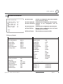
System Initialization
z Clear All Data
Deletes all configuration data and the system
is set to the factory default.
z Clear Display Set Initializes all the configuration data for Display.
z Clear Camera Set Initializes all the configuration data for
Camera.
z Clear Motion Set Initializes all the configuration data for Motion.
z Clear Edit Data
Deletes all the configuration data for Preset,
Swing,Pattern and Group.
z Reboot Camera
Reboots the zoom camera module.
SYSTEM INITIALIZE
------------------------G
CLEAR ALL DATA
NOG
CLR DISPLAY SET
NOG
CLR CAMERA SET
NOG
CLR MOTION SET
NOG
CLR EDIT DATA
NOG
REBOOT CAMERA
NOG
BACKG
EXITG
Factory Default
G
z Display Parameters
Camera ID
PTZ Information
Action Title
Preset Label
Alarm I/O
North Direction
Privacy Zone
ON
AUTO
AUTO
AUTO
AUTO
Pan 0q
Undefined
z Motion Parameters
Motion Lock
Power Up Action
Auto Flip
Jog Max Speed
Jog Direction
Freeze In Preset
Park Action
Alarm Action
OFF
ON
ON
120q/sec
INVERSE
OFF
OFF
OFF
z Camera Parameters
Focus Mode
SemiAuto
Digital Zoom
ON
Image Flip
OFF
Sharpness
16
Stabilization
OFF
White Balance
AUTO
Backlight
OFF
Day&Night
AUTO
Brightness
50
Iris
AUTO
Shutter
ESC
AGC
MIDDLE
SSNR
MIDDLE
SENS-UP
AUTO
z User-Defined Data
Preset 1~128
Swing 1~8
Pattern 1~4
Group 1~8
Undefined
Undefined
Undefined
Undefined
GSpeed Dome Camera Instruction Manual
49/74
Chapter 5.
REMOTE VIDEO
MONITORING
G
Remote Video Monitoring
Remote Video Monitoring
5
5
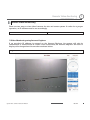
Remote video Monitoring
There are two ways to view video between the site and center system. In order for a proper
operation, an IP address must be set accordingly.
Default ID : admin
Default Password : 1234
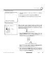
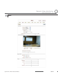
Video Monitoring using Internet Explorer
If an encoder’s IP address is entered on the Internet Explorer, the system will ask for
confirmation to install Active-X control. Once authorized, the Internet Explorer will start to
display video images from the encoder as shown below.
http://192.168.10.100
GSpeed Dome Camera Instruction Manual
51/74
G
Remote Video Monitoring
Remote Video Monitoring
5
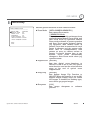
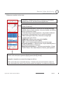
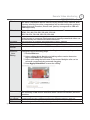
Remote controller in live view
-View Size : Change screen size according to your monitor.
Default value is ‘x1’ and this means original size.
CLICK
-Moving control : place your mouse in the circle and click. PTZ
moves on that way
-Zoom In/Out(Tele/Wide) : zoom in & out current watching.
-HOME : Move to home position. *for more details, see ‘Motion
Setup->Park Action’ setup.
-Focus Near/Far & auto focus button : only works on ‘Manual
focus’ setup. *Not working if it is on ‘auto focus’ status’.
-IRIS Close/Open & Auto Iris : Close Iris on high light
condition and open in low.
-MENU ON : display text menu of IP CAMERA
-Enter : Enter selected menu.(SAVE)
-ESC : cancel current setting and exit to previous page
Set preset position : 1. Place camera on your desired place. 2.
Select preset number. 3. Press set.
Move to preset position : 1. Choose preset number, 2. Press
‘GOTO’ button. *use ‘clear’ button to remove preset position
Select the number of tour and type(pattern, Swing, Group) * this should be defined
first in each menu(see operation page, pattern, Swing, Group)
Snapshot : snapshot on current live image as still cut.
Talk : voice talk over connected devices. * Camera only can send sound to client. To
hear the sound from camera, you should connect microphone on camera and speaker
GSpeed Dome Camera Instruction Manual
52/74
5
G
Remote Video Monitoring
Remote Video Monitoring
5
5
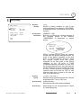
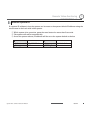
Initialize System IP
If a system IP address is lost, the system can be reset to the system default IP address using the
reset button in the back side of the system.
ཛ While system is in operation, press the reset button for more than 5 seconds.
ཛྷ The system will reboot automatically
ཝ Once the system reboots, IP address will be set to the system default as below.
x IP mode
Fixed IP
x Subnet mask 255.255.255.0
x Base port
2222
GSpeed Dome Camera Instruction Manual
x IP address
x Gateway
x HTTP port
192.168.10.100
192.168.10.1
80
53/74
G
Remote Video Monitoring
Remote Video Monitoring
5
5
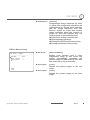
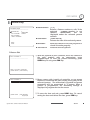
IP finder in remote client
To use IP camera over network, you should set IP address first on your IP camera.
T Prepare Network cable
T Connect to available Network port.
T Find IP address of the network camera with IP installer or IP remote s.w
* IP installer : Find IP address of registered device, update and web connection
IP finder
IP finder searches all available
devices on connected network.
(Available menu is differ to each
model)
To find your device, click ‘Search’ button
and then you can do following process.
-Configuration : Change IP address
-Upgrade : upgrade firmware
-Time zone : change time zone
setup
:
import
setup
-import
configuration files
-Web connection : Connect through
I.explorer.
After Searching, select a device and change IP address according to your network information
and connect through ‘Web Connect’.
GSpeed Dome Camera Instruction Manual
54/74
G
Remote Video Monitoring
Remote Video Monitoring
5
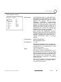
IP finder Configuration
Configuration
In Configuration page, user can setup connection type and IP address information.
- DHCP : Once you select DHCP, it disables IP address information field. To use
this option, you must check your network support DHCP.G
- PPPoE : Use this option when you use WAN service. To use WAN service, you
need ID & Password from your service provider.G
- Static IP : if you know all IP information, select this option.
- Use DDNS : check this option when you use DDNS service.
- Port : shows port numbers which required in communication.
Web connect
Access directly to camera with I.Explorer and user can do remote setup. See
more details on next page.
GSpeed Dome Camera Instruction Manual
55/74
5
G
Remote Video Monitoring
Remote Video Monitoring
5
5
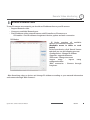
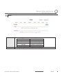
Use Internet Explorer
The server can be configured using web browser. Type IP address in the address input area of
Internet Explorer, then a live viewing screen will be displayed. Press Setup button located in the
upper right area of the monitoring screen, then the setup page for server setup will be displayed.
c Enter IP address
d Press Setup button
The configurations are grouped into 8 categories: System, Video, Audio, Network, Serial,
Event, Preset and User. Any configuration changes are not applied until Apply is pressed.
Leaving the page without pressing Apply button, changes in the page will be discarded.
GSpeed Dome Camera Instruction Manual
56/74
G
Remote Video Monitoring
Remote Video Monitoring
5
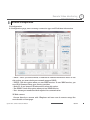
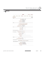
System
G
G
G
G
G
G
G
G
G
G
G
G
G
G
G
G
G
G
G
G
G
Video StandarD
System ID
Language
Firmware
version
Start Time
Current Time
Select NTSC or PAL
Alphanumeric System ID to be transferred to remote software
Language to be used for web-based configuration(English, Japanese
and Korean)
Current firmware version
Latest system boot date and time
Enter a new date and time and press Set Current Time button to
update date & time
Select time zone of where the system is installed. Depending on the
Time Zone
time zone, Daylight Saving Time will work automatically
Synchronize system time with an NTP server using NTP(network time
Automatically
synchronize with protocol). Name of the NTP server should be registered on NTP
server Name.
NTP server
Reboot Server
Factory Reset
Pressing Reboot Server button will cause the system to reboot. Do
not press the Reboot button unless the server needs a reboot.
Back to default(factory default)
GSpeed Dome Camera Instruction Manual
57/74
5
G
Remote Video Monitoring
Remote Video Monitoring
5
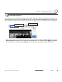
Video
G
G
GSpeed Dome Camera Instruction Manual
58/74
5
G
Remote Video Monitoring
Remote Video Monitoring
5
5
Preference Preference in video compression and transmission: With ‘Bitrate’ selected,
the video compression will be effected by the ‘Bitrate’ value entered. With
‘Quality’ selected, the video compression will be effected by the quality of
image selected. Therefore, ‘Bitrate’ and ‘Quality’ corresponds to CBR and
VBR respectively
Resolution Selectable video compression resolution:
5
NTSC: 720u480, 720u240, 352u480, 352u240
PAL: 720u576, 720u288, 352u576, 352u288
Frame rate Selectable video frame rate: Determine the maximum number of frames of
video images to compress. The frame rate of actually transmitted video can
be affected by the network bandwidth limitation
Quality
The selection is possible with Preference is set to ‘Quality’
Bitrate
The value is applicable when Preference is set to ‘Bit rate’
I-Frame
Possible values between 0 and 255. There will be no I-frames if 0 is selected.
Interval
Motion
Configure regions for motion detection. Regions of arbitrary shape can be
Detection
configured by the following steps.
Area
ཛGEnable Edit item.
Editing
ཛྷGSelect editing Mode. Set is for including cells to motion detection
region and Erase is for excluding.
ཝGSelect cells using the left button of the mouse. Multiple cells can be
selected conveniently by press and dragging.
ཞGPress Apply Edited Area to save the editing.
Sensitivity
Brightness
Contrast
Hue
A condition to trigger an event with motion detection. The value determines
the sensitivity of the motion detection within a block: the smaller, the more
sensitive
Controls input video brightness by selecting values between 0 and 100.
Controls input video contrast by selecting values between 0 and 100
Controls input video Hue by selecting values between 0 and 100
GSpeed Dome Camera Instruction Manual
59/74
G
Remote Video Monitoring
Saturation
Burn-in
OSD
5
Video Monitoring
Controls input video saturation by selecting valuesRemote
between
0 and 100.
Inserts system ID and date/time in the compressed video. Separately
System ID and Time can be turned On or Off in the video. Position
specifies the position of such data
GSpeed Dome Camera Instruction Manual
60/74
5
G
Remote Video Monitoring
Remote Video Monitoring
5
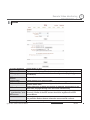
Audio
G
Mode
Select audio operation mode
Mode
Action
Off
No operation
Tx-Only
Transmit only
Rx-Only
Receive only
Tx & Rx
Transmit and Receive
Input Gain
Set audio input gain
GSpeed Dome Camera Instruction Manual
61/74
5
G
Remote Video Monitoring
Remote Video Monitoring
5
Network
G
GSpeed Dome Camera Instruction Manual
62/74
5
G
Remote Video Monitoring
Remote Video Monitoring
IP Mode
Three IP modes are supported. Depending on the selected mode,
further configuration items come as follows.
IP Mode Selection
Description
Fixed IP
Local IP
Fixed IP address
Local
Gateway IP address
Gateway
Local Subnet Subnet mask
൯ Please ask an IP address information from ISP provider or
network manager
DNS
PORT
Set DNS server IP address.
Base Port : communication port for each connection.
HTTP Port : web port(Default is 80)
RTSP Port : default 554
Use when you need RTSP authentication
5
RTSP
authentication
RTSP
Session
SNMP
Bitrate
When several clients connect to a server, bandwidths of networks
clients may differ and some clients may not receive encoded stream
control
fully. To handle such situation, three flow control modes which can be
chosen according to users’ preference are provided
Mode
Description
The bitrate is automatically adjusted to a client with
Min
smallest network bandwidth
The bitrate automatically adjusted to a client with
Max
largest network bandwidth size. When set to this
mode, a client with smaller bandwidth will not
receive all frames of video
The bitrate is adjusted to most optimum rate by
Adjust
learning the network bandwidth
Off
Flow control is off
Address
Info
Display network related information
IP
Address
Current
Domain
MAC
Address
GSpeed Dome Camera Instruction Manual
The server own IP address. This information is
useful when the server’s IP mode is set to DHCP
In case the server is registered with DDNS server,
the registered domain name is displayed
Display the MAC address of the server. In case the
server is registered with DDNS server, the MAC
address is used in DDNS registration
63/74
5
G
Remote Video Monitoring
Remote Video Monitoring
5
5
Serial
This page is used only for developer and test purpose. In this page, user can define serial
connection of camera and this is only used when user control camera as RS485 telemetry. No
available in IP connection control
G
G
RS485 port Set connection type with each connection information. To get detail of
RS-485 connection, refer to PTZ camera’s instructions.
PTZ
Set PTZ type and ID according to configured setup.
Sensor
Set Sensor on/off and connection type.
type
Sensor
Set activating time of sensor on sensor schedule
schedule
Select
Sensor off : no use sensor
Sensor on : Activate sensor by schedule
*To select all, click the rectangle between ‘0’ and ‘SUN’.
QSerial communication information should be synchronized to Analog camera communication
setup.
GSpeed Dome Camera Instruction Manual
64/74
G
Remote Video Monitoring
G
Remote Video Monitoring
5
Event
In this page, user can define alarm activity and notification from local to remote.
Local
On
Disconnect
E-mail
Notification
FTP
upload
Event
Record
Define what type of reaction in local followed by each event. There are
E-mail, FTP and Move to preset position option.
Define what type of reaction will be on when system is disconnected.
Set mail server information to send out e-mail to specified user. Check if
you will include Video Clip or not.
Set FTP server to upload event triggered image data.
Set PRE & POST Recording time and POST Event type.
GSpeed Dome Camera Instruction Manual
65/74
5
G
Remote Video Monitoring
Remote Video Monitoring
5
5
Preset
d Preset Name
c Move Camera to normal view
e Press Set Button
f Save
Preset Configuration
Set the PTZ Presets by following the next steps.
ཛGMove cameras to desired view using PTZ control buttons.
ཛྷGEnter Preset name.
ཝGPress Set button.
ཞ Once all the presets are set, press Save List button.
Move to Preset Position
Select a preset from the Preset and press Go To button, then, the camera will move to the
selected preset position.
GSpeed Dome Camera Instruction Manual
66/74
G
Remote Video Monitoring
Remote Video Monitoring
5
5
User
G
User can be registered and authority level of a user can be specified. User configuration is
allowed only to admin user. MAX. 16 users can be registered and each user can have one of
four authorities.
Authority
Level
Admin
Manager
User
Guest
Allowed Operations
Remarks
All operations
User ID = admin
All operations except for user
configuration
Live viewing and PTZ control
Live viewing only
GSpeed Dome Camera Instruction Manual
67/74
G
Remote Video Monitoring
Remote Video Monitoring
5
5
Add User
Page for adding a user comes on pressing Add button.
User ID and password need to be entered and privilege level need to be selected. User ID and
password consist of alphanumeric string of MAX. 15characters.
Delete User
A user is deleted by pressing Delete button.
Change Password
Pressing Modify Password button after selecting a user shows a page for changing password.
In case of changing admin password, the old password is checked.
Modify Privilege Level
Pressing Modify Privilege button after selecting a user shows a page for changing the
authority. It is not allowed to change the authority level of admin user.
Login Policy
Skip Login is provided for convenient access to the server when authentication is not
required. When Skip Login is set to Enable, login step is skipped. The privilege level after
login in this way is determined by the setting of Privilege Level After Login Skipped.
GSpeed Dome Camera Instruction Manual
68/74
Chapter 6.
SPECIFICATIONS
G
SPECIFICATIONS
6
Specifications
NETWORK
Ethernet 10/100 Base-T(RJ45)
Network
TCP/IP,UDP, Multicast, DHCP, PPPoE, SMTP, HTTP, SNMP
H.264
32Kbps ~ 4Mbps
NTSC : 720u480, 720u240, 352u480, 352u240
Resolution
PAL
: 720u576, 720u288, 352u576, 352u288
Video
NTSC : Max. 30fps
PAL : Max. 25fps
Max Frame Rate
PAL : 0.2 ~ 25fps
Frame Rate Range NTSC : 0.2 ~ 30fps
Sensitivity adjustable
Motion Detection
G.711
Standard
8KHz
Sample Rate
64Kbps
Audio
Data Rate
1 Line-In (Mini-Stereo)
Input
1 Line-Out (Mini-Stereo)
Output
Camera Live View & Audio/Video snapshot, PTZ control,
Video Access fromWeb-Browser Remote Setup, Remote Upgrade
Multiple user access levels with password protection, IP
address filtering, HTTPS encryption, IEEE 802.1u
Security
authentication
Max 36 Channel Monitoring simultaneously
PTZ Control
Live Monitoring
Event Monitoring
Bi-directional Audio communication
CMS
Time/Camera-Base/Event-Base
Search/Playback
Multi-channel viewing of recorded status on timeline
Export to AVI file
Backup
Snapshot to BMP file
Network Interface
Network Protocol
Standard
Data Rate
GSpeed Dome Camera Instruction Manual
70/74
G
SPECIFICATIONS
CAMERA PART
Video Signal Format
Image Sensor
Total Pixels
Effective Pixels
Horizontal Resolution
Video Signal-to-Noise
Zoom
Forcal Length
Angle ofView
Zoom Speed
Minimum Illuminance
Day & Night
Focus
Iris
Shutter Speed
AGC
White Balance
BLC
Flickerless
SSNR
Privacy Zone
Stabilization
NTSC
PAL
1/4'' Super HAD color CCD
811(H)u508(V) 410K
795(H)u596(V) 470K
768(H)u494(V) 380K
752(H)u582(V) 440K
550 TV Lines(Color), 680 TV Lines(B/W)
50 dB (AGC Off)
u27 Optical Zoom, u12 Digital Zoom
F1.6~2.9, f=3.5~94.5mm
H : 55.5q(Wide)~2.24q(Tele) / V : 42.5q(Wide)~1.79q(Tele)
1.8 sec (Wide to Tele)
0.4 Lux (Color) / 0. 02 Lux (B/W), 50 IRE / F1.6
Auto / Day / Night(ICR)
Auto / Manual / SemiAuto
Auto / Manual
u256 ~ 1/120000 sec
Low / Middle / High / Manual / Off
Auto / Manual(Red, Blue Gain Adjustable. 1800qK~10500qK)
BLC / Off
Selectable
Low / Middle / High / Off
8 Masks, Spherical Coordinate
ON / OFF
G
GSpeed Dome Camera Instruction Manual
71/74
6
G
SPECIFICATIONS
MECHANISM PART
Movement
Range
Speed
Pan
Tilt
Preset
Jog
Swing
Preset
Pattern
Swing
Group
Other Pan/Tilt Functions
Communication
Protocol
OSD
Sensor Input and
Alarm Outputs
Fan
Heater
360q(Endless)
90q
360q/sec.
0.05 ~ 360q/sec. (Proportional to Zoom)
1~ 180q/sec.
127 Presets (Label, Independent Camera Parameter Setting)
4 Patterns [1200 Commands(Approx. 5 Minute) / Pattern]
8 Swings
8 Groups (MAX. 20 Actions with The Combination of Preset,
Pattern and Swing)
Auto Flip, Auto Parking, Power Up Action and etc.
RS-485
Pelco-D, Pelco-P Selectable
English, Menu / PTZ information etc
3 Inputs, Photo-Coupler Type, DC 5V~12V
1 Output, Relay Output, MAX. Load DC24V 1A
Always ON
Operation Start from Internal Temperature 10qC
Operation Temperature
-30qC ~ 50qC
RATED POWER
DC12V
GSpeed Dome Camera Instruction Manual
DC 12V / 3.0 A
72/74
6
G
SPECIFICATIONS
MECHANICAL
Wall Mount
Material
Dome
Internal
External
Dome Size
Dimension
Weight
Polycarbonate
Polycarbonate,ABS
Aluminium
150mm / 5.9”
310u279.5 mm
Approx 4.5Kg
[Note]
1) Specification and features are subject to change without prior notice.
2) Specification and features are different by models.
3) Check the voltage and current capacity of rated power carefully.
GSpeed Dome Camera Instruction Manual
73/74
6
G
SPECIFICATIONS
6
Dimension
z Main Body
z Wall Mount Type
[Unit : mm]G
G
GSpeed Dome Camera Instruction Manual
74/74