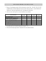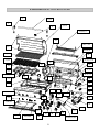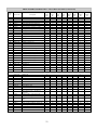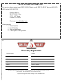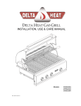
1
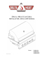
DELTA HEAT GAS GRILL INSTALLATION, USE & CARE MANUAL Models: P/N: 18617N (01/14) DHBQ26G-B DHBQ32G-B DHBQ32R/S-B DHBQ38R/S-B A special message… Congratulations on your purchase of Delta Heat gas barbecue grill. Delta Heat is committed to making outdoor cooking products you’ll be proud to own for years. This manual gives you easy to follow instructions for installing, operating and maintaining your Delta Heat grill. We recommend reading this manual carefully before your first use to ensure safety, proper care and operation. Thank you and welcome! Delta Heat _____________________________________________________________________ FOR YOUR RECORDS Please record the following information and refer to them when contacting the company or an authorized service agent. This information is found on the data nameplate, located on the rear panel of the grill. A second label with model number and serial number is located under the right side of the control panel. Model #: ________________________________ Serial #: _________________________________ Date of Purchase: __________________________ Place of Purchase: __________________________ Type of Gas: NG LP IMPORTANT SAFETY INFORMATION – DELTA HEAT GAS GRILL WARNING! Read this manual carefully and completely before using your grill to ensure proper operation, proper installation, proper servicing and to reduce the risk of fire, burn hazard and/ or other injury. FOR YOUR SAFETY If you smell gas: 1. Shut off gas to the appliance. 2. Extinguish any open flames. 3. Open lid. 4. If odor continues, keep away from the appliance and immediately call your gas supplier or fire department. AVERTISSEMENT S’il y a une odeur de gaz: 1. Coupez l’admission de gaz de l’appariel. 2. Éteindre toute flamme nue. 3. Ouvrir le couvercle. 4. Si l’odeur continue, évite l’appareil et appelle tout de suite votre fournisseur de gaz ou les pompiers. AVERTISSEMENT FOR YOUR SAFETY 1. Do not store or use gasoline or other flammable vapors and liquids in the vicinity of this or any other appliance. 2. An LP cylinder not connected for use shall not be stored in the vicinity of this or any other appliance. 1. Ne pas entreposer ni utiliser de l’essence ni d’autres vapeurs ou liquides inflammables dans le voisinage de l’appareil, ni de tout autre appareil. 2. Une bouteille de propane qui n’est pas raccordée en vue de son utilisation, ne doit pas être entreposée dans le voisinage de cet appareil ou de tout autre appareil. THIS GRILL IS FOR OUTDOOR USE ONLY: CE GRIL EST POUR UTILISATION à If stored indoors, detach and leave L.P. cylinder L’ExTéRIEUR SEULEMENT: outdoors. Si l’appareil est entreposé à l’interieur, enlever les bouteilles et les laisser à l’extérieur. BEFORE LIGHTING 1. Read instructions before lighting. 2. Open lid during lighting. 3. If ignition does not occur in 4 seconds, turn the burner control(s) off, wait 5 minutes, and repeat the lighting procedure. AVANT D’ALLUMER L’APPAREIL 1. Lisez les instructions avant d’allumer l’appareil. 2. Ouvrez le couvercle avant d’allumer l’appareil. 3. Si l’appareil ne s’allume pas en 4 secondes, fermez le robinet du brûleur, attendez 5 minutes, et procédez de nouveau à l’allumage. GENERAL SAFETY REQUIREMENTS: 1. The installation of this appliance must conform with local codes or, in the absence of local codes; either the National Fuel Gas Code, ANZI Z223.1/NFPA 54, or the CAN/CGA-B149.1, Natural Gas Installation Code or CAN/CGA-B149.2, Propane Installation Code. 2. This outdoor cooking gas appliance is not intended to be installed in or on recreational vehicles and /or boats. 3. This outdoor cooking gas appliance is intended for use outdoors and shall not be used in a building, garage or any other enclosed area. 4. Minimum clearance of 12 inches from the back and sides of the grill to adjacent combustible construction must be maintained. This outdoor cooking gas appliance shall not be located under overhead-unprotected combustible construction. 5. The utilization of an external electrical source requires that when installed, this outdoor cooking gas appliance must be electrically grounded in accordance with the local codes or, in the absence of local codes, with the National Electrical Code, ANSI/NFPA 70, or the Canadian Electrical Code, CSA C22.1. Keep any electrical supply cord, or the rotisserie motor cord and the fuel supply hose away from any heated surfaces. 6. Keep your grill in an area clear and free from combustible materials, gasoline and other flammable vapors and liquids. 7. DO NOT obstruct the flow of combustion and ventilation air to this appliance. Keep the ventilation openings of the cylinder enclosure free and clear from debris. 8. Check all gas connections for leaks with soapy water solution and brush. Never use an open flame. (Reference page 8 for leak test procedure). 9. Check flexible hoses for cuts and wear that may affect the safety before each use. 10. Never use charcoal in the grill. 11. Never use the grill in a windy area. 12. Never use the grill without the drip pan installed and push all the way to the back of the grill. Without the drip pan, hot grease and debris could leak downward and produce a fire hazard. 13. The pressure regulator and hose assembly supplied with the Delta Heat Gas Grill must be used. Replacement pressure regulators and hose assemblies must be those specified by Delta Heat. 14. CALIFORNIA PROPOSITION 65-WARNING: The burning of gas cooking fuel generates some by-products which are on the list of substances known by the State of California to cause cancer or reproductive harm. California law requires businesses to warn customers of potential exposure to such substances. To minimize exposure to these substances always operate this unit according to the use and care manual, ensuring you provide good ventilation when cooking with gas. In Massachusetts: All gas products must be installed using a “Massachusetts” licensed plumber or gasfitter. A “T” handle type manual gas valve must be installed in the gas supply line to this appliance. This applies to permanently installed Natural Gas and propane installations. This does not apply to propane portable installations using a 20 pound tank. TABLE OF CONTENTS – DELTA HEAT GAS GRILL GETTING STARTED…………………………………………………………………… ….. 2 GAS REQUIREMENTS o GAS SAFETY REQUIREMENT……………………………………………... 4 o LP GAS HOOKUP………….………………………………………………… 5 o PORTABLE LP CONNECTION………….………………………………….. 6 o NATURAL GAS INSTALLATION………………………………………….. 7 o LEAK TEST…………………………………………………………………… 8 ELECTRICAL REQUIREMENTS …………………………………………………..……… 9 WIRING DIAGRAM…………………………………………………………………..……..… 10 LOCATING THE GRILL o CLEARANCE TO COMBUSTIBLE CONSTRUCTION……………………... 11 o CLEARANCE TO NONCOMBUSTIBLE CONSTRUCTION……………..… 11 CUTOUT DIMENSIONS o GRILL………………………………………………………………………….. 12 ASSEMBLY INSTRUCTIONS o BRIQUETTE TRAY…………………..……………………………………….. 13 o WARMING RACK…………………………………………………………… 13 o ROTISSERIE…………………………...……………………………………… 14 o BATTERY LOCATION ………………………………………………………. 14 OPERATING INSTRUCTIONS o BEFORE LIGHTING THE GRILL…………………………………………… 15 o TO LIGHT THE GRILL BURNER ………………………………………….. 15 o MATCH LIGHTING INSTRUCTIONS ……..……………………………… 16 o USING THE GRILL …………………………………………………………… 16 o INTERIOR LIGHT OPERATION AND LIGHT BULB REPLACEMENT……. 16 o USING THE ROTISSERIE BURNER……………..…………………………….. 17 o SEAR ZONE BURNER …………………………....…………………………..… 17 CLEANING AND MAINTENANCE o STAINLESS STEEL…………………………………………………………… 18 o COOKING GRATES ………………………………………………………… 18 o CERAMIC BRIQUETTE TRAY….…………………………….………….… 18 o U-BURNER & SEAR ZONE BURNER……………………………………… 19 o DRIP PAN ………………….………………………………………………… 19 o SPIDER AND INSECT WARNING…………………………………………… 19 TROUBLE SHOOTING GUIDE…………………...………………………………………… 20 REPLACEMENT PARTS o EXPLODED VIEW………………………………………….…………………. 21 o REPLACEMENT PARTS LIST…………………………..……………….……. 22 o LIMITED PRODUCT WARRANTY………………………………………...…. 24 o WARRANTY REGISTRATION CARD ………………………………………. 25 GETTING STARTED – DELTA HEAT GAS GRILL 1. Remove all packaging materials, labels and protective plastic film. DO NOT LEAVE UNIT UNDER THE SUN WITH PROTECTIVE PLASTIC FILM ON FOR A LONG PERIOD OF TIME AS IT WILL BECOME DIFFICULT TO REMOVE THE FILM. 2. Check to ensure that all grill accessories listed below are included. Grill Accessories Grate, Stainless Steel Briquette Tray Assy. (Standard Grill) Rotisserie Motor with bracket (s/s) Regulator, NG (NG Grills Only) Regulator, LP (LP Grill ONLY) Warming Rack, (s/s) Spit Rod, (s/s) Meat Holder Forks (pair) (s/s) DHBQ 26G-B 2 2 DHBQ 32G-B 3 3 1 (1) 1 1 (1) 1 DHBQ 32R/S-B 3 3/2 1 1 (1) 1 1 1 3. Assemble parts as per assembly instructions on page 13-14. 4. Fill out the Warranty Registration Card and mail it to the indicated address. DHBQ 38R/S-B 3 3/2 1 1 (1) 1 1 1 GETTING STARTED – DELTA HEAT GAS GRILL 2 5. Get familiar with the knobs and burners identification below. DHBQ26G-B DHBQ32G-B Grill Burner Sear Zone (Opt) Grill Burner Grill Burner Sear Zone (Opt) Grill Burner DHBQ32R/S-B Grill Burner / Sear Zone Grill Burner DHBQ38R/S-B Rotisserie Grill U-Burner (Standard) located underneath the briquette trays. Grill Burner Grill Burner / Sear Zone Sear Zone Burner usually located on the left side. (Standard on RS Models and Optional on R & G Models) Rotisserie Grill Burner Infrared Rotisserie Burner located on the rear panel above the grates. (32R/S & 38R/S Models Only) GAS SAFETY REQUIREMENTS – DELTA HEAT GAS GRILL 3 Each appliance is set and tested at the factory for the type of gas supply to be used. Identify the type of gas, either Natural Gas or LP gas and make sure that the marking on the data plate (rating plate) matches the gas being supplied to the grill. The data plate is located on the rear panel of the grill. A second label with model number and serial number is located under the right side of the control panel. All gas connections should be made by a qualified technician and in accordance with local codes and ordinances. The installation must conform with local codes or, in the absence of local codes, with either the national Fuel Gas Code, ANSI Z223.1/NFPA 54, or CAN/CGA-B149.1, Natural Gas Installation Code or CAN/CGA-B149.2, Propane Installation Code. WARNING: 3 CHECK TO ENSURE THAT THE GAS SUPPLY HOSE DOES NOT COME IN CONTACT WITH ANY HOT SURFACE OF THE GRILL. NEVER CONNECT THE GRILL TO AN UNREGULATED GAS SUPPLY. L.P. GAS (LIQUIFIED PETROLEUM /PROPANE) If your grill is factory built for L.P., the regulator supplied is set for 11” water column and is for use with L.P. gas only. The factory-supplied regulator and hose must be used with a 20 lb. L.P. cylinder. L.P. GAS SAFETY REQUIREMENT The LP-gas supply cylinder must be constructed and marked in accordance with the Specifications for LP-gas Cylinders of the U.S. Department of Transportation (D.O.T.) or the National Standards of Canada CAN/CSA-B339, Cylinders, Spheres and Tubes for the Transportation of Dangerous Goods, and Commission, as applicable; and 1. Provided with a listed overfilling prevention device. 2. Provided with a cylinder connection device compatible with the connection for outdoor cooking appliances. It must be provided with a shut-off valve terminating in gas tank valve outlet. It must include a collar to protect the cylinder valve. The cylinder supply system must be arranged for vapor withdrawal. Do not operate the gas grill indoors or in any enclosed area. If the gas grill is not in use, the gas must be turned off at the supply cylinder. If the grill is to be stored indoors, disconnect the gas supply cylinder and leave the cylinder outdoors. 4 LP GAS HOOK-UP – DELTA HEAT GAS GRILL Install the factory-supplied hose and regulator assembly as shown. Connect the 3/8” flare end of the hose to the grill coupling using a ¾” open wrench. Do not apply pipe sealant to the 3/8” flare connection. Connect the regulator to the LP cylinder hand tighten it, do not use a wrench. Check for leaks using soapy water solution. (Reference page 8 for leak test procedure). Note: An enclosure for LP gas cylinder must be vented on the level of the cylinder valve and at floor level. The effectiveness of the opening(s) for purposes of ventilation shall be determined with the LP gas supply cylinder in place. This shall be accomplished by one of the following: a. One side of the enclosure shall be fully open; or b. For an enclosure having four sides, a top and a bottom: 1. At least two ventilation openings at cylinder valve level shall be provided in the sidewall, equally sized, spaced at 180 degrees (3.14 rad), and unobstructed. Each opening shall have a 2 total free area of not less than 1/2 square inch per pound (7.1 cm /kg) of stored fuel capacity 2 and not less than a total free area of 10 square inches (64.5 cm ). Ventilation opening(s) shall be provided at floor level and shall have a total free area of not less than ½" square inch per pound (7.1 cm2/kg) of stored fuel capacity and not less than a total free area of 10 square inches (64.5 cm2). If ventilation openings at floor level are in a sidewall, there shall be at least two openings. The bottom of the openings shall be at floor level and the upper edge no more than 5 inches (127 mm) above the floor. The openings shall be equally sized, spaced at 180 degrees (3.14 rad) and unobstructed. 5 PORTABLE LP CONNECTION – DELTA HEAT GAS GRILL NOTE: USE ONLY A 20-LBS. (5-GALLON CAPACITY) GAS CYLINDER. WARNING: DO NOT PLACE MORE THAN ONE CYLINDER IN THE BASE CABINET ENCLOSURE AT ANY TIME. WARNING: DO NOT USE A DENTED OR RUSTED LP CYLINDER. NEVER USE A CYLINDER WITH A DAMAGED VALVE. ALWAYS CHECK FOR LEAKS AFTER CHANGING THE LP CYLINDER. (Page 8) THE LP PRESSURE REGULATOR AND HOSE SUPPLIED WITH THIS UNIT MUST BE USED WITHOUT ALTERATION. ALWAYS USE THE TANK SECURING DEVICE SUPPLIED WITH GRILL BASE. 1) To install the gas cylinder, place the cylinder onto the provided cutout. 2) Check to ensure that the tank’s gas valve on top of the cylinder is closed. 3) Connect the LP regulator (included) to the cylinder and hand-tighten only. Open the tank valve and make sure all connections are leak tight using a soapy water solution and a brush. (Reference page 8 for leak test procedure). 6 NATURAL GAS INSTALLATION – DELTA HEAT GAS GRILL The installation must conform with local codes or, in the absence of local codes, with either the national Fuel Gas Code, ANSI Z223.1/NFPA 54, or CAN/CGA-B149.1, Natural Gas Installation Code or CAN/CGA-B149.2, Propane Installation Code. 1. This gas appliance and its individual shutoff valve must be disconnected from the gas supply piping system during any pressure testing of that system at the test pressures in excess of 1/2 psi (3.5 kPa). 2. This appliance must be isolated from the gas supply piping system by closing its individual manual shutoff valve during any pressure testing of the gas supply piping system at test pressures equal to or less than 1/2 psi (3.5 kPa). If the gas grill is factory built for Natural Gas, the regulator supplied is set for 4” water column. The regulator is convertible to 10” water column for plumb-in system LP application. Do not use with a 20-lb LP cylinder. Make sure that the regulator is set for the correct gas type. To check, remove the brass hex cap. You will find the conversion plastic pin attached to the cap to the underside of the cap. If the disc (1/2 in. diameter) of the pin is close to the cap, then the regulator is set for Natural Gas. If the disc is at the tip of the pin, away from the brass cap, the regulator is set for system LP application. To convert to Natural Gas, remove the plastic conversion pin and invert and replace it back in a manner such that the disc is close to the brass cap. For both Natural and LP, the maximum inlet pressure is 14” water column. A typical Natural Gas installation is shown below. Make sure that the factory-supplied regulator is used and installed with the arrow mark on the regulator pointing towards the gas grill. Do not use any replacement regulator other than that specified by DELTA HEAT. Use only pipe sealants that are approved for use with Natural and LP gases. An installer-supplied gas shutoff valve must be installed in an accessible location. 7 LEAK TEST – DELTA HEAT GAS GRILL CAUTION BEFORE TESTING Finding and/or fixing a gas leak is NOT a “DO-IT-YOURSELF” procedure. NEVER USE THE GRILL WITHOUT FIRST LEAK TESTING THE GAS CONNECTIONS. WARNING: DO NOT USE OPEN FLAME TO CHECK FOR LEAKS. USE OF AN OPEN FLAME COULD RESULT IN A FIRE, EXPLOSION, BODILY HARM OR DEATH. DO NOT SMOKE WHILE PERFORMING THE LEAK TEST! To prevent fire or explosion hazard, DO NOT use or permit sources of ignition in the area while performing a leak test. Perform leak test outdoors only. Check to ensure that flexible hoses do not have any cuts and wear that may affect the safety before each use. Only the factory supplied hose and regulator must be used. Use only replacement regulator and hose assemblies specified by DELTA HEAT. LEAK TEST 1) Prepare a leak testing solution of sudsy water by mixing in a spray bottle with half liquid soap and half water. 2) Confirm that all control knobs are in the OFF position. 3) Turn the main gas valve supply ON. 4) Apply leak testing solution by spraying on the pipe joints, fittings, and hose. 5) A gas leak is detected if; a) there is a faint gas smell and/or… b) …growing bubbles appear on any of the connection points and/or hose, DO NOT attempt to ignite the grill and IMMEDIATELY turn off the gas supply valve. 6) When there is a gas leak, call a qualified service technician. DO NOT use the grill until the leak is corrected. 8 ELECTRICAL REQUIREMENTS – DELTA HEAT GAS GRILL TO INSTALL AND SECURE POWER TRANSFORMER Grill models with interior lights have a power transformer with an attached power supply cord. This transformer must be secured in a dry location and away from the grill firebox and excessive heat area. a. In a base cart application, four mounting screws with nuts are provided at the bottom left rear corner of the cart. If not provided, drill four holes using the transformer box as a template. Secure the transformer box as shown. (Fig. 1) b. In a built-in application secure the transformer box near the GFCI 120V outlet in a dry location and away from the grill firebox and excessive heat area. c. Make the transformer connections to the wire harness plug located at the left rear of the front panel to the harness of the transformer box. (Fig. 2) d. Plug-in the transformer’s power cord to the properly grounded GFCI 120V outlet. e. A side burner plug to provide electrical power for side burner is located at the right rear of the front panel. (Fig. 3) Fig. 2 Fig. 1 Fig. 3 ROTISSERIE MOTOR: (Motor Specification: 40 lbs. / in; 0.5A; 15W; 60 Hz.) The rotisserie motor requires 120 volt supply. Simply plug the motor into a properly grounded GFCI 120 volt outlet at either side of the grill. WARNING AVERTISSEMENT Electrical Grounding Instructions: This outdoor gas cooking appliance is equipped with a three prong (grounding) plug for your protection against shock hazard and should be plugged directly into a properly grounded three prong outlet. Do not cut or remove the third prong from this plug. Instruction pour la mise à la terre electrique: Cet appareil est muni d’une fiche à trois broches (mise à la terre) afin de vous protéger des chocs et doit être branché directement dans une prise de courant à trois broches adéquatement mise à la terre. Il ne faut pas couper ou enlever la broche de mise à la terre de cette fiche. 9 WIRING DIAGRAM – DELTA HEAT GAS GRILL DHBQ26G-B DHBQ32G-B DHBQ32R/S-B DHBQ38R/S-B 10 LOCATING THE GRILL – DELTA HEAT GAS GRILL This gas appliance is designed and certified for outdoor use only. Do not locate this grill under overhead combustible surfaces. Do not operate the grill inside a building, garage, recreation vehicle or any enclosed area. When choosing an area, consider exposure to wind, proximity to traffic paths and length of gas supply line. Keep gas supply lines as short as possible to reduce pressure drop. Keep the grill away from windy area but keep the grill in a well-ventilated area. Do not obstruct the flow of combustion and ventilation air around the grill. The supporting edges of the grill must be located level and flat. The counter should also be leveled. CLEARANCE TO COMBUSTIBLE CONSTRUCTION A minimum clearance of 12” from the sides and 12” from the back of the grill to adjacent vertical combustible construction must be maintained. DÉGAGEMENT DE TOUTE CONSTRUCTION COMBUSTIBLE Il faut maintenir une distance minimum de 12 po (30.48 cm) sur les côtés et de 12 po (30.48 cm) sur l’arrière du gril par rapport aux constructions combustibles verticales adjacentes. CLEARANCE TO NONCOMBUSTIBLE CONSTRUCTION A minimum clearance of 3” from the back of the grill above cooking surface to non-combustible construction is required to allow the grill hood to open completely. A minimum of 6” clearance to the sides of the grill above cooking surface to non-combustible construction is recommended to provide space for the rotisserie motor and the spit rod. The grill can be installed directly next to non-combustible construction below the cooking surface. DÉGAGEMENT DE TOUTE CONSTRUCTION INCOMBUSTIBLE Une distance minimum de 3 po (7.62 cm) de l’arrière du gril au-dessus de toute surface de cuisson à la construction incombustible est prescrite pour permettre à la hotte d’ouvrir complètement. Une distance minimum de 6 po (15.24 cm) des côtés du gril au-dessus de la surface de cuisson à la construction incombustible est recommandée pour prévoir de l’espace pour le moteur de la rôtissoire et la poignée des broches de cuisson. Le gril peut être installé directement à proximité d’une construction incombustible en-dessous de la surface de cuisson. 11 GRILL CUT-OUT DIMENSIONS – DELTA HEAT GAS GRILL DHBQ38R/S-B (AS SHOWN) DHBQ32R/S-B DHBQ32G-B DHBQ26G-B DETAIL 19 3/4 WIDTH OF UNIT (26, 32, 38) SEE DETAIL (TYPICAL TO ALL TOP UNITS) 12 ASSEMBLY INSTRUCTIONS – DELTA HEAT GAS GRILL The DELTA HEAT Grill is produced fully assembled and tested in the factory and requires no major assembly in the field. For the purpose of safe shipping and transit, some parts such as the briquette trays and rotisserie components are wrapped inside the grill and require minor assembly. Check to ensure that all packaging material have been removed prior to grill operation. TO INSTALL BRIQUETTES TRAYS 1. Put briquette trays into the grill above the burner as shown by lining up the tab with the channel of the briquette tray. 2. Then put the stainless steel grates over the briquette trays. TAB CHANNEL WARMING RACK LEVEL POSITIONS: The warming rack may be used to keep food warm and avoid overcooking the food. To install the warming rack, use the hook to latch on at the rear hood panel as shown below (Fig. 3) When the warming rack is not in use, it should be installed in a stow-away position (Fig. 4). Fig. 3 Fig. 4 13 ASSEMBLY INSTRUCTIONS – DELTA HEAT GAS GRILL ROTISSERIE ASSEMBLY For Larger Loads 1. Install the rotisserie motor horizontally as shown. The motor socket hole will line up with the front notch of the saddles. 2. Insert the rotisserie rod into the motor socket hole and place the rod on the front notch of each saddle. 3. Remove the stainless steel grates. 4. Place a basting pan on top of the briquette trays to catch the drippings. (basting pan not supplied) For Smaller Loads 1. Install the rotisserie motor horizontally as shown. The motor socket hole will line up with the rear notch of the saddles. 2. Insert the rotisserie rod into the motor socket hole and place the rod on the rear notch of each saddle. 3. Place a basting pan on top of the stainless steel grates to catch the drippings (basting pan not supplied) 4. BATTERY LOCATION INSTALL THE BATTERY AS SHOWN 14 OPERATING INSTRUCTIONS – DELTA HEAT GAS GRILL BEFORE LIGHTING THE GRILL DO NOT ATTEMPT TO LIGHT THE GRILL IF YOU SMELL GAS. WARNING! IT IS CRITICAL THAT THE GAS BURNERS ARE PROPERLY INSTALLED WITH THEIR ORIFICES INSIDE THE BURNERS AIR SHUTTERS. If not properly installed, gas may leak outside of the burner that could lead to fire, potential damage to your grill, bodily injury or death. Inspect the gas supply piping or hose prior to turning the gas ON. If there is evidence of cuts, wear, or abrasion, it must be replaced prior to use. The replacement pressure regulator and hose assembly must be the type specified by the manufacturer. Do not use the grill if the odor of gas is present. The pressure regulator and hose assembly supplied with the units must be used. If the unit is LP, screw the regulator and hand tighten to the valve of the cylinder and leak check the hose and regulator connections with a soap and water solution before operating the grill. Reference page 8 for leak test procedure. Always keep your face and body as far away as possible when lighting. Refer to spiders and insects warning and procedure under the cleaning and maintenance page of this manual. TO LIGHT THE GRILL BURNER Lighting the Grill 1. Open the grill hood completely. Do not attempt to light the grill with the hood closed. 2. Open the gas supply shut-off valve. 3. Push in the knob and verify that the spark igniter sparks. If the igniter does not spark, check the 9V battery. (Reference page 14 for battery location). 4. Once the sparking is verified simultaneously push-in and turn the knob counter-clock-wise to the biggest flame marking on the knob. Hold the knob pushed in for 4 seconds. Once you see or hear a flame you can release the knob. For Rotisserie Lighting Push-in and turn the knob to HIGH. Hold for 30 seconds to heat up the safety thermocouple and release knob. If the rotisserie burner will not stay lit, repeat the process. CAUTION: If ignition does not take place within 4 seconds, turn knob to the OFF position, wait for five minutes and repeat step 3 and 4. 5. Close the hood to allow the grill to pre-heat until the hood thermometer displays the desired grilling temperature. 15 OPERATING INSTRUCTIONS – DELTA HEAT GAS GRILL Match/BBQ Lighter Lighting Instructions: If there is no electrical power supply available or if spark igniter will not light the burners, the burners can be lit manually using a lighted long match, taper or BBQ lighter. 1. Push and turn the knob counter-clock-wise to the biggest flame marking on the bezel. Hold the knob pushed in for 4 seconds. 2. Using the provided match holder, insert a lit match or BBQ lighter thru the grates and near the top of the cross tube of the burner. Once you see or hear a flame you can release the knob. Important: If burner fails to light within 4 seconds, turn off gas and wait 5 minutes before repeating the process. Warning: If you smell gas, shutoff the gas supply and immediately check for leaks using the soapy water technique. (See Page 8) USING THE GRILL 1. Check to be certain that the drip pan is in place and pushed all the way into the grill. 2. Light the grill burners using the instructions in use and care manual. 3. Turn the control knobs to HI and allow the grill to preheat for 15 minutes or until desired temperature is displayed on the thermometer. The top cover is to be closed during the appliance preheat period. 4. Place the food on the grill and cook to the desired temperature doneness. Adjust heat setting, if necessary. The control knob may be set to any position between HI and LO. 5. Allow grill to cool then you may clean the drip pan after each use. INTERIOR LIGHT OPERATION The DELTA HEAT grill is equipped with interior halogen lights for late night grilling. The grill is equipped with a switch that controls the functionality of the interior lights. 1. Push the switch located on the left side of front panel to turn ON interior. WARNING: Do not touch the interior halogen lights. It may be hot and can cause serious burns. REPLACING INTERIOR LIGHT BULBS WARNING! Unplug the grill from the 120V power source before replacing the light bulb. 1. Remove the screw that holds the lens cover and slide the lens cover out. 2. Remove the housing from the grill. 3. Loosen the screws that hold the bulb in the light housing. 4. Remove the old light bulb by pulling it straight out of the socket without twisting the light bulb. 5. Wearing plastic gloves, insert the new light bulb into the socket. DO NOT touch bulb with bare hands as the oil and dirt will shorten bulb life. 6. Slide the light lens back into the light assembly and screw it in to secure it. 16 OPERATING INSTRUCTIONS – DELTA HEAT GAS GRILL USING THE ROTISSERIE BURNER (For DHBQ32R-B & DHBQ38R-B Units) The Rotisserie system rotates the food in front of infrared burner heat for even cooking and juicier taste. 1. Install the rotisserie motor on the motor bracket and plug it in to proper voltage. Reference electrical requirements. (Page 9) 2. Insert the food on the middle of the spit rod and then secure it with the meat holders on both ends by tightening the thumb screws on the meat forks. If multiple pieces of food will be cooked at the same time, make sure the load is evenly balanced on the spit rod. Proper weight balancing will lead to evenness of cooking and prolong the life of the rotisserie motor. 3. Insert the spit rod in the rotisserie motor at desired cooking position. You may need to remove the cooking grates to create clearance for bigger loads of foods. Reference assembly instructions for rotisserie assembly instructions. (Page 14) 4. Locate the rotisserie knob which is the second knob from the left. 5. Push-in and turn the knob counter-clock-wise to the biggest flame marking on the knob. Hold the knob pushed in for 30 seconds and release knob. If the burner will not stay lit, push and hold for another 30 seconds. Once lit, the rotisserie burner will reach cooking temperature in about 1 minute. CAUTION: If ignition does not take place within 4 seconds, turn knob to the OFF position, wait for five minutes and repeat step 5. NOTE: Once the burner reached cooking temperature, adjust to low flame setting by turning the knob to the low flame marking without pushing in on the knob. 6. Once cooking is completed, shut-off the rotisserie burner and main valve. WARNING: When using the rotisserie always keep the front hood closed except when basting or checking the meat for cooking completion. It is recommended to use a meat thermometer to check if the food is completely cooked. CAUTION: In sunny or heavy light environments, the flame from the infrared rotisserie burner may be difficult to see and verify complete ignition. NOTE: The rotisserie motor must be stored in an area secured from the surrounding elements when not in use. Do not leave it mounted on the grill. SEAR ZONE BURNER (For DHBQ32RS-B & DHBQ38RS-B Units) Searing steaks and other meats with infrared sear burner at the beginning of the grilling cycle helps lock in juices and flavor. Sear the meats quickly with the front hood open, followed by regular grilling over the U-burner. CAUTION Never allow excessive amount of liquids to come in contact with the Infrared Sear Zone burner since it could cause damage to the ceramic tiles. DO NOT place briquette tray over sear burner. This will block the infrared heat and will damage the tray. Allow burner to warm up for ten minutes before adjusting to low setting. 17 CLEANING & MAINTENANCE – DELTA HEAT GAS GRILL STAINLESS STEEL The DELTA HEAT grill is made of all welded stainless steel. It is non-rusting and nonmagnetic. Never clean the stainless steel when it is hot. After the initial grilling use, certain areas of the grill may discolor. This is a normal discoloration caused by the intense heat given off by the burners. Specks of grease can gather on the surface of the stainless steel and get baked-on. These can be removed by using a mild abrasive pad (like Scotch Brite) with a stainless steel cleaner. Use the mildest cleaner and always scrub in the direction of the grain. Do not use steel wool to clean the grill. Do not use abrasives on the polished highlights. Be extra careful when cleaning around the highlights. Metal polisher or mild chrome cleaner can be used to bring back the luster on highlights. To touch-up minor scratches in the stainless steel, sand the affected surface very lightly, with 100-dry grit emery sandpaper in the direction of the grain. COOKING GRATES The easiest way to clean the stainless steel grates is to scrub them with a barbeque brush immediately after cooking is completed and the flame is turned off. Wear a barbeque mitt to protect your hands from the heat and steam. Dip a brass bristle barbeque brush in tap water and scrub the hot grill. Dip the brush frequently in tap water. Steam, created as water comes in contact with the hot grill, helps loosen food particles stuck in the grill. These food particles will either get burned into the briquettes or fall into the cleaning pan. Cleaning of the grill would be longer and more difficult if the grill racks are allowed to cool before cleaning. When cleaning the grates, make sure not to hit the rotisserie burner. Never spray water on hot grill. p CERAMIC BRIQUETTE TRAY It is not necessary to remove and clean the briquettes from the tray after every grilling. They burn themselves clean during the next cooking operation. Periodically, the briquette trays need to be cleaned. Remove them from the grill, shake free loose of the debris and wipe the trays clean. Do not handle a hot briquette tray. REPLACING BRIQUETTE TRAYS 1) Remove the trim that holds the briquettes. 2) Remove the old briquettes and place the new briquettes on the same location as the old ones. 3) Replace the trim that holds briquette. CAUTION DO NOT place briquette trays over the infrared sear zone burner. This will block the infrared heat and will cause damage to the tray. 18 CLEANING & MAINTENANCE – DELTA HEAT GAS GRILL BURNERS Burners are made of heavy gauge stainless steel and can be soaked in water and cleaned with a wire brush. Check every port hole for clogs. Use a wire pin to clean out clogged ports. Make sure the burner is dry before installing it back into the grill. INFRARED SEAR ZONE BURNER The infrared burner has stainless housing and protective screen. The protective screen helps reflect heat up to the cooking surface and also catches any food particles from landing on the ceramic burner. At the searing temperatures that the burner reaches, all food particles will be burned off so the only maintenance required is cleaning the protective screen and checking for any objects that may be trapped. DRIP PAN The drip pan collects grease, liquid and fallen food particles. Allow the pan and its contents to cool before cleaning. Slide the pan out and wipe it clean. Make sure the drip pan is fully inserted back into the grill. It is highly recommended to clean the pan after every use to avoid any possibility of a grease fire. DO NOT use the grill without the drip pan pushed all the way to the back of the grill unit. SPIDER AND INSECT WARNING Spiders and other insects can nest in the burners of this and any other grills, which causes the gas to flow from the front of the burner. This dangerous “condition” can cause a fire behind the valve panel, damaging the grill and making the grill unsafe to operate. Inspect the burners once a year or if the grill has not been used for more than one month or if any of the following conditions occur: 1) The smell of gas in conjunction with the burner flames appearing yellow. 2) The grill does not reach temperature. 3) The grill heats unevenly. 4) The burners make popping noises. 19 TROUBLESHOOTING GUIDE – DELTA HEAT GAS GRILL BEFORE CALLING FOR SERVICE: If your DELTA HEAT grill does not function properly, use the following troubleshooting guide before contacting your dealer for service. The troubleshooting guide may save the cost of a service call and the inconvenience of being without your grill. PROBLEM Grill will not light. WHAT TO DO 1. Push in the knob and verify that the spark igniter functions. 2. If the igniter does not spark, replace 9V battery. a. Purge the line of any trapped air. b. Check if you can match-light the burner. c. Check to see that the other burners operate. NOTE: It is normal to hear a popping sound when the grill burners are first turned ON. Burner flame is yellow and gas odor can be smelled. Low heat generated with knob in HI position. Too much heat. Excessive flare-up. Burner blows out Interior light will not turn ON. Spark igniter does not spark. Thermometer is not reaching high temperatures 1. 2. 3. 1. 2. 3. 4. 5. 6. 1. 2. 1. 2. 1. 2. 3. 4. 5. 6. 1. 2. Check the burner inlet for obstruction…ex. Spiders, insects, etc. Check the air shutter for proper adjustment. Check any source of gas leak. Check if the problem is isolated to only one burner. If it appears so, clean the orifice and burner, clearing ports of any obstruction. Check for any bent or kinked fuel hose. Check if the air shutter is properly adjusted. Check for proper gas supply and pressure. Pre-heat grill for 15 minutes. If using LP gas, check for empty tank. Check for damaged orifice or no orifice. Check for unauthorized regulator adjustment. Check if the cooking grids are dirty. Clean if necessary. Overload from fatty meats or excessive cooking temperature. Check for any burner defect. Check for proper burner installation. Check if fuel mixture is too lean. Check if gas supply is sufficient. Check if LP tank is empty. Check if the grill location is subject to high winds. Check if the unit is plugged into proper voltage (GFCI 120V). Replacement of the light bulb may be required. 1. If the igniter does not spark, replace 9V battery. 1. Allow the grill 15 minutes with hood closed at high setting in order to reach higher temperatures. 20 EXPLODED VIEW – DELTA HEAT GAS GRILL 1 3,4,5 2 8,9,10 6 11,12,13 15 16,17,18 83 29,30,31 55, 56 20 53,54 75,76,77,78 27 14 58 22 73,74 52 70,71,72 67,68,69 32 7 51 62 61 50 63 25 26 34,35,36,37 28 64 23, 24 19 21 59 79,80,81 60 82 65 41, 42 44 43 38,39,40 66 57 49 33 45,46,47,48 21 REPLACEMENT PARTS LIST – DELTA HEAT GAS GRILL Item No. TE Part No. 1 2 3 4 5 6 7 8 9 10 11 12 13 14 15 16 17 18 19 20 21 22 S13113 S13134 S12351 S12352 S12353 S15343 S22141 S23231-26Y S23231-32Y S23231-38Y S13841 S13842 S13889 S21813 S16340 S23227-26 S23227-32 S23227-38 S23216 S16270 S16318 S13330 23 S13883 24 25 26 27 28 29 30 31 32 33 34 35 36 37 38 39 40 41 42 43 44a 44b S13890 S16303 S16268 S22083 S13865 S23220-26 S23220-32 S23220-38 S23206 S16272 S23202-26GY1 S23202-32GY1 S23202-32RY1 S23202-38RY1 S23203-26 S23203-32 S23203-38 S13163 S14232 S13162-02 S13191 S13165 S12751YN S12751YL S12752GYN S12752GYL S12752RYN S12752RYL S12753YN S12753YL S16273 S23229 S16274 S13365 S23218-38Y S23218-32Y 45 46 47 48 49 50 51 52 53 54 Description Handle Bracket Handle Bracket Insulator Tube Handle 24.6” S/S Handle Tube Handle 30.6” S/S Handle Tube Handle 36.6” S/S Handle Hood Thermometer / Bezel / Nut Bracket, Mount Igniter, IR 26” Hood Assembly 32” Hood Assembly 38” Hood Assembly 26” Warming Rack 32” Warming Rack 38” Warming Rack Motor Bracket Rotisserie Motor Top, Rear Hood Cover, 26” Top, Rear Hood Cover, 32” Top, Rear Hood Cover, 38” Bracket, Ignition Module Halogen Light Led, Red Infrared Rotisserie Burner Stainless Steel Spit Rod (26”/32”) Stainless Steel Spit Rod (38”) Safety Thermocouple I.R Igniter Cover, IR Igniter Stainless Steel Meat Forks Bottom, Rear Hood Cover, 26” Bottom, Rear Hood Cover, 32” Bottom, Rear Hood Cover, 38” Baffle, Air Stop Battery Pack Front Panel , DHBQ26G Front Panel, DHBQ32G Front Panel, DHBQ32R Front Panel, DHBQ38R 26” Drip Pan Handle 32” Drip Pan Handle 38” Drip Pan Handle Delta Heat Logo Logo Clip Delta Heat Knob Knob Bezel (No Graphics) Knob, Bezel, (With Graphics) Manifold Assembly (26”) NG Manifold Assembly (26”) LP Manifold Assembly (32G”) NG Manifold Assembly (32G”) LP Manifold Assembly (32R”) NG Manifold Assembly (32R”) LP Manifold Assembly (38”) NG Manifold Assembly (38”) LP Light Switch Spacer, Briquette Tray Spark Igniter (U-Burner) Stainless Steel U-Burner Briquette Tray Assembly, 26, 38 Briquette Tray Assembly, 32 2 2 DHBQ 32R/SBN 2 2 DHBQ 32R/SBL 2 2 1 1 1 1 1 1 1 1 1 1 1 1 1 1 DHBQ 26G-BN DHBQ 26G-BL DHBQ 32G-BN DHBQ 32G-BL 2 2 1 2 2 1 2 2 1 1 1 1 1 DHBQ 38R/SBN 2 2 DHBQ 38R/SBL 2 2 1 1 1 1 1 1 1 1 1 1 1 1 1 1 1 1 2 4 1 1 1 2 4 1 1 1 1 1 1 1 1 1 1 1 1 3 1 1 3 1 1 1 1 1 2 4 4 4 1 1 2 4 4 4 1 1* 1* 1 1* 1* 1 1 1 1 1 1* 1* 1* 1* 1 1 1 1 1 1 1 1 1 1 2 1 1 2 1 2 3 1 2 3 1 2 4 1 1 2 4 1 1* 1* 1* 1* 1 1 1* 1* 1 1 1 1 1 1 1 1 1 1 1 1 3 1 3 1 3 1 3 1 1 1 1 1 1* 1 1* 1 2 1 1 2 1 1 1 1 1 2 2 2 2 1 1 2 2 2 2 1 1 1 1 1 2 3 3 3 1 2 3 3 3 1 2 4 4 4 1 2 4 4 4 1 1 1 1 1 1 1 4 1 2 2 1 4 1 2 2 Note: * = Optional 22 1 6 2 3 1 6 2 3 1 6 2 3 1 6 2 3 3 3 3/2 3/2 1 6 2 3 3/2 1 1 6 2 3 3/2 REPLACEMENT PARTS LIST – DELTA HEAT GAS GRILL (CONTINUED) Item No. TE Part No. 55 56 57 58 59 60 61 62 63 64 65 66 67 68 69 70 71 72 73 74 75 76 77 78 79 80 81 82 83 S13884 S13838 S16317 S13129 S13367 S13366 S12602 S15344 S15303 S16281-1 S15132 S15136 S23210-26 S23210-32 S23210-38 S14224 S14111 S14105 S23222-L S23222-R S23221-26G S23221-32G S23221-32R S23221-38R S23217-26 S23217-32 S23217-38 S13876 S14128 Description Stainless Steel Grates, 10” Stainless Steel Grates 12” Ignition Module Briquettes Only Wire, Mesh (IR Sear Zone Burner) I.R. Sear Zone Burner Brass Coupling ( 3/8 Flare x ½ FIP ) LP Regulator with Hose Assembly NG Regulator AC Adaptor Gas Valve Safety Gas Valve (I.R Burner) Bracket, Crossover, 26 Bracket, Crossover, 32 Bracket, Crossover, 38 Spacer, hood ½ x 7/8 SS Tube Screw, ¼-20 x 1 ¼, Ph Truss SS Nut, ¼-20 Serr., Hex, Flange SS Rear Hood Side, Left, DHBQ Rear Hood Side, Right, DHBQ Rear Hood Liner, DHBQ26G Rear Hood Liner, DHBQ32G Rear Hood Liner, DHBQ32R Rear Hood Liner, DHBQ38R Drip Pan, 26 Drip Pan, 32 Drip Pan, 38 Holder, Match W/Lanyard Hood Bumper DHBQ 26GBN DHBQ 26GBL 2 1 40 1* 1* 2 1 40 1* 1* 1 1 1 1 2 1 2 1 1 2 2 2 1 1 1 1 1 4 2 2 2 1 1 1 DHBQ 32GBN 3 DHBQ 32GBL 3 DHBQ 32R/SBN 3 DHBQ 32R/SBL 3 1 60 1* 1* 1 60 1* 1* 1 1 1 60 / 40 1 1 1 60 / 40 1 1 1 1 1 1 3 1 3 1 1 3 1 1 3 1 2 2 2 2 2 2 2 1 1 2 2 2 1 1 2 2 2 1 1 2 2 2 1 1 1 1 1 1 DHBQ 38R/SBN DHBQ 38R/SBL 3 1 60 / 40 1 1 3 1 60 / 40 1 1 1 1 1 1 3 1 1 3 1 2 2 2 2 1 1 2 2 2 2 1 1 1 1 1 1 4 1 1 4 1 1 4 1 1 1 1 1 4 1 4 1 4 1 4 Non-Shown Replacement Part List S15133-47 S15133-49 S15133-56 S15108-51 S15108-57 S16320Y S16331Y S16328Y S16334Y S12601 S12640 S12401 S16290 S14121 S14275 S15141 S16288 S22059 Orifice, #47 Orifice, #49 Orifice, #56 Orifice, #51, Rotis Orifice, #57, Rotis Wire Harness, 26G Wire, Harness, 32G Wire Harness, 32R Wire Harness, 38R Elbow, Brass 3/8 CC x 1/8 FIP (Gas valve side) I.R Brass Elbow, (I.R. Burner side) I.R. Flexible Tubing Fuse, 6.3A 250V 5x20mm Slow-Blow Glass 6-32 x ¼ PH Pan Type F Bezel Screw Screw, 10-24 x ½, PH, Pan, Type F, SS Brass, Plug Sear Zone Burner Electrode Sear Zone Burner Collector Box 2 3 3 2 3 3 3 1 3 1 1 1 1 1 1 1 1 1 1 1 1 1 1 1 1 1 1 1 1 1 1 1 1 1 1 1 1 1 1 1 4 23 4 23 8 29 8 29 8 29 1* 1* 6 29 1 1* 1* 8 29 1* 1* 6 29 1 1* 1* 1 1 1 1 1 1 1 1 Note: * - Optional 23 DELTA HEAT GRILL WARRANTY FIFTEEN YEAR LIMITED WARRANTY: Delta Heat warrants the stainless steel grates and fabricated stainless steel housing to be free from defects in materials and workmanship under normal residential use for fifteen years from the original date of purchase. This warranty excludes grills used in rental or commercial applications. This warranty does not apply to rust, corrosion, discoloration, surface scratches, weather and atmospheric related staining, and oxidation which are normal conditions and to be expected with any outdoor product unless the affected component becomes inoperable. This warranty does not cover labor or labor related charges. The actual part will be repaired or replaced with the owner paying for all other costs, including labor, installation, shipping and handling charges. TEN YEAR LIMITED WARRANTY: Delta Heat warrants the stainless steel burners to be free from defects in materials and workmanship under normal residential use for a period of ten years from the original date of purchase. The actual part will be repaired or replaced, free of charge, with the owner paying for all other costs including labor, installation, shipping and handling charges. ONE-YEAR FULL WARRANTY: Delta Heat warrants the outdoor gas grill and all of its component parts including briquette trays (excluding the briquettes), optional flame tamers, ignition system, gas system, lights, rotisserie motor, infrared burners, etc, to be free from defects in materials and workmanship under normal residential use for a period of one year from the original date of purchase. The actual part will be repaired or replaced, free of charge, with the owner paying for all other costs including labor, installation, shipping and handling charges. NINETY (90) DAY RESIDENTIAL PLUS WARRANTY: This warranty applies to applications where use of the product extends beyond normal residential use such as bed and breakfast inn, private clubs, multi-dwelling condos and apartments. The actual part will be repaired or replaced, free of charge, with the owner paying for all other costs including labor, installation, shipping and handling charges. This warranty excludes all commercial locations such as restaurants and food service locations. WARRANTY LIMITATIONS & EXCLUSIONS This warranty shall apply only to the products purchased and located in the continental United States and Canada. The warranty coverage begins on the original date of purchase and proof of date of purchase is required. In order to activate the warranty, we require that you send in the attached warranty registration card. This warranty applies only to the original owner and may not be transferred. This warranty does not apply to damages resulting from negligence, alteration, misuse, abuse, accident, natural disaster, loss of electrical power to the product for any reason, improper installation or improper operation, unauthorized adjustments or calibrations, dings, dents, scratches, or damages due to harsh cleaning chemicals. This warranty does not apply to rust, corrosion, discoloration, surface scratches, weather and atmospheric related staining and oxidation which are normal conditions and to be expected with any outdoor products unless the affected component becomes inoperable. This warranty does not apply to commercial use, or to products with altered or removed serial numbers. Delta Heat shall not be liable for incidental, consequential, special or contingent damages resulting from its breach of this written warranty or any implied warranty. WARRANTY SERVICE & REPLACEMENT PARTS: Call your authorized selling dealer or call Delta Heat directly at 800-422-0091. Be prepared to furnish the following information: Purchaser’s name, model and serial number of the grill, date of purchase and the accurate description of the problem. Delta Heat will not pay for service calls for correcting an installation problem. Owner shall be responsible for proper installation, providing normal care and maintenance, providing proof of purchase upon request and making the grill accessible for service. In the event of any warranty replacement, all removal, replacement, installation and shipping costs are the responsibility of the grill owner. Some states do not allow limitations on how long an implied warranty lasts, or the exclusions of or limitations on consequential damages. This warranty gives you specific legal rights and you may have other rights, which vary from state to state. 24 HOW TO OBTAIN SERVICE For service, please contact your DELTA HEAT dealer or call DELTA HEAT direct at (800) 4220091 or fax (562) 802-3391 Mailing address: DELTA HEAT, Inc. 13231 166th Street Cerritos, CA 90703 Visit us at www.deltaheat.com Please provide: Model number Serial Number Date of installation A description of the problem Cut Here Warranty Registration Customer Name Model # Address Serial # City Date Purchased Zip Dealer’s Name Phone # Dealer’s Address e-mail: This Warranty Registration card must be returned within thirty days of purchased to properly activate your warranty. This information is for our internal use only. Or you may register online at http://www.deltaheat.com Cut Here Place Postage Here Customer Service ATTN: Warranty Department 13231 166th Street Cerritos, CA 90703