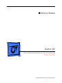
1
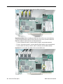
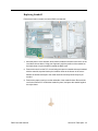
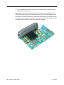
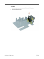
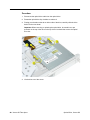
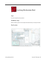
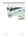
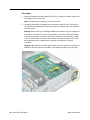
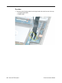
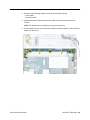
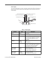
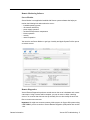
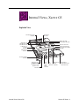
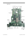
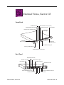
Service Source Xserve G5 Xserve G5, Xserve G5 (Cluster Node), and Xserve G5 (January 2005) Updated: 11 March 2005 © 2005 Apple Computer, Inc. All rights reserved. Service Source Take Apart Xserve G5 © 2005 Apple Computer, Inc. All rights reserved. General Information Overview Xserve G5 is a server designed to mount into a rack; Apple recommends that you remove the Xserve G5 server from the rack before replacing or installing all parts except hard drives. You can replace hard drives while the server is operating and still in the rack. To identify versions of the Xserve G5, check the front panel. Xserve G5 and Xserve G5 (January 2005) include a slot-load optical drive and three hard drives. Xserve G5 (Cluster Node) has no optical drive and just one hard drive. Note: For the most part, the procedures in this chapter apply to all versions of the server. When different procedures are required, the version is specified in the topic heading. Using 2 Gigabyte Memory Modules 2 gigabyte memory modules became a configurable purchase option for Xserve G5 computers starting in March 2005. Only Xserve G5 version 2 logic boards labeled as shown below accept 2 gigabyte (GB) memory modules (DIMMs). Check for this label before you install memory or change logic boards. General Information Xserve G5 Take Apart - 1 Important: There are two versions of the Xserve G5 logic board that must be replaced like-for-like. Identify version 2 logic boards by the “DDR 2GB” (Double-Data-Rate, 2 gigabyte memory) label as shown below. Mounting in a Rack For information on mounting Xserve G5 in a rack, see the Xserve G5 User’s Guide. Tools You will need a medium and a small Phillips screwdriver and a small flat-blade screwdriver for some procedures. If the server is locked, you will also need the server’s Allen wrench key. Note: Many take-apart procedures do not require tools. Server Identifier Light/Button The identifier light on the server’s front panel turns on when internal sensors or a systems administrator detects a problem with the server. (The light can also be turned on by pressing the identifier button.) This indicator will help you locate which server in a rack needs servicing. In addition, you can use the identifier button to initiate several firmware commands to the system. See “Entering Firmware Boot Commands From the Front Panel” in the Troubleshooting chapter. Note: A duplicate identifier light/button is on the server’s back panel. 2 - Xserve G5 Take Apart General Information Before Opening the Server Serial Number Be sure to write down the server’s serial number. If the server’s software must be set up after service is complete, the serial number will be required for login. Unlocking the Server If the server is in the locked position (the yellow security LED on the front panel is on), use the Allen key that came with the server to unlock it. Important: When the lock on the server’s front panel is locked, the software ignores the optical drive, keyboard and mouse, and other peripherals connected to the USB and FireWire ports on the server. Shutting Down You must shut down the server before replacing or installing all parts except the hard drives. Before shutting down, be sure to alert users that the server will be unavailable for a period of time. Warning: After shutting down the server, you must wait a few minutes before servicing it to allow internal components to cool. Electrostatic Discharge (ESD) Precautions Follow these steps to avoid damage from ESD before working inside the server. 1. Shut down the server. 2. If the cable management arm is not in use, unplug all external cables except the power cord. 3. Touch the server’s metal case to discharge static electricity. 4. Unplug the power cord. 5. Slide the server open, remove it from the rack, and place it on a flat surface, preferably covered by an ESD mat. 6. Put on an ESD wrist strap, and to avoid static electricity building back up in your body, do not walk around the room until after you have finished and closed the server. Top Cover The top cover is attached to the rack where the server is mounted. If you are replacing the top cover, you must remove it both from the server and from the rack. For detailed information on how the top cover is mounted in the rack, see the User’s Guide. General Information Xserve G5 Take Apart - 3 Hard Drive Xserve G5 and Xserve G5 (January 2005) include three hard drive bays at the front of the server; Xserve G5 (Cluster Node) includes just one drive bay. Drives come as modules attached to carriers; they are removed from or installed in the server as a unit. Note: Blank drive carriers, which may fill some of the hard drive bays, follow the same take-apart procedure as hard drives. If you are replacing a blank carrier with a drive module, instruct the server’s administrator to keep the blank for possible future use. Blank carriers must be installed in all empty bays to maintain proper airflow through the server. Tools No tools are required for this procedure. Preliminary Steps Before you begin, make sure the drives are in the unlocked position. No other preliminary steps are required. You can replace or install hard drives while the server is running; you do not need to shut down or open the server first. Note: There are two LED indicators on the front of each drive. • The upper LED shows drive status: a green light indicates the drive is good; a yellow or red light indicates the drive should be replaced. • The lower LED shows drive activity: when the light is blinking, the system is reading from or writing to the drive. To avoid losing data, never remove a drive when the lower LED is blinking. WARNING: Drives must be in the unlocked position before you attempt to remove a drive. If the drives are locked, pulling on the drive to remove it could damage the drive handle. Part Location 4 - Xserve G5 Take Apart Hard Drive Procedure 1. Make sure the drive being replaced is not in use by any application and is not being shared by the server. (See the Mac OS X Server documentation for information about shared drives.) 2. Unmount the drive (by using the command-line tools or by dragging the disk icon to the Trash). 3. Press the handle on the front of the drive module so that the handle pops out. 4. Wait for the upper LED on the drive to go out. Then grasp the drive handle, and pull the drive module out of the server. Hard Drive Xserve G5 Take Apart - 5 Opening the Server The server slides open from the front of the rack. The server’s top cover remains in place in the rack; the bottom housing (containing all internal components) should be placed on a sturdy, flat surface. Tools No tools are required for this procedure. You may, however, find a Phillips screwdriver useful in releasing the thumbscrews in step 1 below. Preliminary Steps Before you begin this procedure, write down the server’s serial number located on the back panel. If it is necessary to set up the server’s software after service is complete, the serial number will be required for login. 6 - Xserve G5 Take Apart Opening the Server Procedure 1. Release the two thumbscrews at the front of the server. Note: The thumbscrews are captive and do not separate from the bottom housing. 2. Grasp the thumbscrews and slide the bottom housing forward part way to expose the two chassis levers. 3. While depressing both levers, pull the bottom housing all the way forward and remove it from the rack. Place the bottom housing on a sturdy, flat surface and ESD mat. Opening the Server Xserve G5 Take Apart - 7 DIMMs Xserve G5 has eight Dual Inline Memory Module (DIMM) slots arranged in two banks. The slots accept Double-Data-Rate (DDR) Synchronous Dynamic Random-Access Memory (SDRAM) devices. Depending on your configuration, the computers ship with a pair of DIMMs installed in slot 1 of each DIMM bank. You can add DIMMs, provided they are installed in pairs of equal size, one per bank, from the center outward. Numbers marked on the logic board next to the DIMM slots illustrate how the pairs must be installed. In addition, DIMMs must fit these specifications: • PC3200 error-correcting DDR SDRAM, also known as DDR-400 • 2.5 volt • 64-bit wide, 184-pin module • 18 memory devices maximum • Unbuffered (not registered or buffered) • Maximum height of 1.25 inches 8 - Xserve G5 Take Apart DIMMs Important: Always install DIMMs in pairs of equal size. Memory from older Macintosh computers is not compatible with Xserve G5. Do not use older memory, even if it fits into the DIMM slots. Caution: Do not install 2 GB DIMMs in Xserve G5 main logic boards that did not previously have 2 GB DIMMs installed. Only Xserve G5 main logic boards labelled “DDR 2GB” accept 2 GB DIMMs. Refer to the Logic Board procedure for more information. Tools No tools are required for this procedure. Preliminary Steps Before you begin, open the server and place the bottom housing on a sturdy, flat surface. Part Location DIMMs Xserve G5 Take Apart - 9 Procedure 1. Push down the ejectors on the DIMM slot. 2. Holding the DIMM by both top corners, lift it straight up out of the server. Warning: When removing or installing the DIMM, handle it only by the edges. Do not touch its connectors. Lift the DIMM straight up from the connector to remove it, and insert it straight down into the connector to install it. Do not rock the DIMM from side to side. Replacement Note: The DIMM is designed to fit into the slot only one way. Be sure to align the notch in the DIMM with the small rib inside the slot. 10 - Xserve G5 Take Apart DIMMs PCI or PCI-X Card In both Xserve G5/Xserve G5 (January 2005) and Xserve G5 (Cluster Node), there are two slots available for PCI or PCI-X expansion cards. The slots are on a riser card located at the back corner of the logic board. The server accommodates PCI or PCI-X cards that meet the following requirements: • 32 or 64-bit data width • 33, 66, 100, or 133 MHz frequency (133 MHz is available only when a single card is installed; if two cards are installed, both cards operate at the speed of the slower card.) • 3.3 volt signaling (PCI-X cards must have a 3.3 volt connector or a universal connector to fit into the expansion slots; cards with a 5 volt connector will not work in this server.) • 7 to 12 inches long Important: Be sure to check the documentation that came with any PCI or PCI-X card to verify that it is compatible with Xserve G5. Some cards may need to be installed in a specific slot in the riser card. Note: Maximum power consumption for both expansion slots combined should not exceed 30 watts. Check the documentation with each card to be sure the cards don’t exceed this limit. Tools No tools are required for this procedure. You may, however, find a Phillips screwdriver useful in releasing the thumbscrew in step 1 below. Preliminary Steps Before you begin, open the server and place the bottom housing on a sturdy, flat surface. PCI or PCI-X Card Xserve G5 Take Apart - 11 Part Location 12 - Xserve G5 Take Apart PCI or PCI-X Card Procedure Note: If you are removing a RAID card, refer to the following Take Apart topic “RAID Card.” 1. Release the thumbscrew that secures the card(s) to the back of the server and swing the metal cover open. Note: The thumbscrew is captive; you cannot remove it. 2. If any 12-inch card is installed, slide the card guide toward the front of the server to release the card. 3. Carefully pull the PCI card back from the connector on the PCI riser. Then tilt the card up so that its port clears the enclosure, and remove the card from the server. Warning: When removing or installing a PCI card, handle it only by the edges. Do not touch its connectors or any of the components on the card. Lift the card straight out from the connector to remove it, and insert it straight into the connector to install it. Do not rock the card from side to side and don’t force the card into the slot. Once the replacement card is installed, pull on it gently to check that it is properly connected. PCI or PCI-X Card Xserve G5 Take Apart - 13 RAID Card and Standoff Tools No tools are required for this procedure. You may, however, find a Phillips screwdriver useful in releasing the thumbscrew in step 1 below. Preliminary Steps Before you begin, open the server and place the bottom housing on a sturdy, flat surface. Part Location 14 - Xserve G5 Take Apart RAID Card and Standoff Procedure 1. Release the thumbscrew that secures the PCI/PCI-X card(s) to the back of the server and swing the metal cover open. Note: The thumbscrew is captive; you cannot remove it. 2. Carefully pull the RAID card back from the connector on the PCI riser. Then tilt the card so that its cables clear the enclosure, and lift the card a short distance out of the server. Warning: When removing or installing the RAID card, handle it only by the edges. Do not touch its connectors or any of the components on the card. Lift the card straight out from the connector to remove it, and insert it straight into the connector to install it. Do not rock the card from side to side and don’t force the card into the slot. Once the replacement card is installed, pull on it gently to check that it is properly connected. Important: Be careful not to lift the card too high or with too much force, because it is attached to the server by the card cables. You’ll detach the cables in the next step. RAID Card and Standoff Xserve G5 Take Apart - 15 3. Turn the card over and disconnect the three RAID card cables. Replacement Note: Before installing the RAID card in the PCI riser, do the following: 1) Plug the backup battery cable into the connector on the card. 2) Connect the three RAID card cables to card connectors as illustrated below: • To port 0 (nearest the fence), connect cable A (longest, may be blue-banded) • To port 1 (second from fence), connect cable B (middle-length, may be red-banded) • To port 2 (third from fence), connect cable C (shortest, may be white-banded). Important: Do not connect any cable to Port 3 on the RAID card. 16 - Xserve G5 Take Apart RAID Card and Standoff Replacing Standoff Follow these steps to replace a missing RAID card standoff.. 1. Mark the postion of the standoff, which will be installed in the hole in the corner of the card where shown above. Using your fingernail ,mark the position of the standoff on the black sheet of mylar insulation beneath the RAID card. 2. Remove the card from the PCI slot and using the square of double-stick tape included with the standoff, tape the black mylar insulation sheet to the bottom of the server. Adhere the double-stick tape to the metal chasis floor directly below the spot you marked. 3. Remove the paper covering from the underside of the standoff’s base. Re-install the card in the bottom PCI slot with the standoff in place, and press the standoff against the mylar sheet. RAID Card and Standoff Xserve G5 Take Apart - 17 PCI Riser Tools No tools are required for this procedure. You may, however, find a Phillips screwdriver useful in releasing the thumbscrew in step 1 below. Preliminary Steps Before you begin, open the server and place the bottom housing on a sturdy, flat surface. Part Location 18 - Xserve G5 Take Apart PCI Riser Procedure If all cards installed are the standard 7-inch version, you can remove the cards and riser as a unit. However, if a RAID card or a 12-inch card is installed, you must disconnect the card from the riser before removing the riser from the server. (See step 2 below.) 1. Release the thumbscrew that secures the card(s) to the back of the server and swing the metal cover open. Note: The thumbscrew is captive; you cannot remove it. 2. If any 12-inch card is installed, slide the card guide toward the front of the server to release the card. Then remove the card from the riser. 3. Lift the latches slightly on either side of the riser connector to release it from the logic board. 4. Pull the riser back from the logic board, and remove the riser and PCI card(s) from the server. PCI Riser Xserve G5 Take Apart - 19 5. If you are replacing the riser, disconnect the PCI card(s) from the original riser and transfer them to the new riser. Warning: When removing or installing a PCI card, handle it only by the edges. Do not touch its connectors or any of the components on the card. Lift the card straight out from the connector to remove it, and insert it straight into the connector to install it. Do not rock the card from side to side and don’t force the card into the slot. Once the replacement card is installed, pull on it gently to check that it is properly connected. 20 - Xserve G5 Take Apart PCI Riser Power Supply Fan Duct Tools The only tool required for this procedure is a small flat-blade screwdriver. Preliminary Steps Before you begin, open the server and place the bottom housing on a sturdy, flat surface. Part Location Power Supply Fan Duct Xserve G5 Take Apart - 21 Procedure 1. Insert a small flat-blade screwdriver under the latch at the right side of the duct and pry the latch forward until it releases the duct from the enclosure. 2. Repeat step 1 for the left latch. 3. Holding the duct at both ends, lift it straight up and remove it from the server. 22 - Xserve G5 Take Apart Power Supply Fan Duct PCI Fan Duct The PCI fan is attached to a plastic duct; you remove the fan and duct as a unit. Tools The only tool required for this procedure is a small flat-blade screwdriver. Preliminary Steps Before you begin, open the server and place the bottom housing on a sturdy, flat surface. Part Location PCI Fan Duct Xserve G5 Take Apart - 23 Procedure 1. Insert a small flat-blade screwdriver under the latch at the side of the PCI fan duct and pry the latch forward until it releases the duct from the enclosure. 2. Holding the duct at both ends, lift it straight up a short distance. 3. Disconnect the PCI fan cable from the logic board. 4. Remove the PCI fan duct from the enclosure. 24 - Xserve G5 Take Apart PCI Fan Duct PCI Fan The PCI fan is located inside the PCI fan duct. Tools No tools are required for this procedure. Preliminary Steps Before you begin, do the following: • Open the server and place the bottom housing on a sturdy, flat surface. • Remove the PCI fan duct. Part Location PCI Fan Xserve G5 Take Apart - 25 Procedure 1. Remove the three screws that mount the PCI fan to the PCI fan duct. 2. Remove the fan from the duct. 26 - Xserve G5 Take Apart PCI Fan Optical Drive, Xserve G5 Note: The Xserve G5 (Cluster Node) server does not include an optical drive. Tools The only tool required for this procedure is a jeweler’s Phillips (#0) screwdriver. Preliminary Steps Before you begin, open the server and place the bottom housing on a sturdy, flat surface. Part Location Optical Drive, Xserve G5 Xserve G5 Take Apart - 27 Procedure 1. Disconnect the optical drive cable from the optical drive. 2. Rotate the optical drive clip clockwise to release it. 3. Placing your thumbs on the tab on either side of the drive, carefully slide the drive back from the front bezel. Important: When removing or replacing the optical drive, be careful not to put pressure on the top of the drive or the top of the front bezel that covers the optical drive slot. 4. LIft the drive out of the server. 28 - Xserve G5 Take Apart Optical Drive, Xserve G5 Replacement Note: Before installing the replacement drive, you must transfer the side brackets and the screws from the original drive to the replacement drive. 5. Remove the mounting screw for the left bracket and transfer the bracket to the new drive, using the same screw to secure it. 6. Remove the three mounting screws for the right bracket and transfer the bracket to the new drive, again using the same screws to secure it. Optical Drive, Xserve G5 Xserve G5 Take Apart - 29 Optical Drive Cable, Xserve G5 Tools No tools are required for this procedure. Preliminary Steps Before you begin, do the following: • Open the server and place the bottom housing on a sturdy, flat surface. • Remove the power supply fan duct. Part Location 30 - Xserve G5 Take Apart Optical Drive Cable, Xserve G5 Procedure Warning: The optical drive cable is attached to the enclosure with adhesive on the underside of the cable. 1. Carefully pry the cable’s adhesive from the enclosure. 2. Disconnect the optical drive cable from the optical drive. 3. Disconnect the cable from the logic board and remove the cable from the server. Optical Drive Cable, Xserve G5 Xserve G5 Take Apart - 31 Processor Important: The heatsink is part of the processor in Xserve G5/Xserve G5 (January 2005); do not attempt to remove the heatsink from the processor. Tools The only tool required is a Phillips screwdriver. Preliminary Steps Before you begin, open the server and place the bottom housing on a sturdy, flat surface. Part Location 32 - Xserve G5 Take Apart Processor Procedure 1. Lift the processor cap straight up and remove it from the processor/heatsink. Note: The cap is attached to the processor by four pegs. Lift up in the areas illustrated below. Processor Xserve G5 Take Apart - 33 2. Using a Phillips screwdriver, remove the six screws that mount the heatsink and processor to the logic board. Replacement Note: There are two different types of processor mounting screws. When installing the processor, first replace the two shorter screws in the screw holes indicated by the squares in the illustration below. Then install the four longer screws in the screw holes indicated by the circles. 3. Carefully lift the heatsink and processor straight up and out of the server. Replacement Note: If you are replacing the processor in a uniprocessor configuration, make sure you install the processor in the connector nearest the PCI fan duct. If a single processor is installed in the other processor connector, the server will not start up properly. Processors in a dual-processor server may be installed in either connector. 34 - Xserve G5 Take Apart Processor Fan Array Tools No tools are required for this procedure. You may, however, find a Phillips screwdriver useful in releasing the thumbscrews in step 3 below. Preliminary Steps Before you begin, do the following: • Open the server and place the bottom housing on a sturdy, flat surface. • Remove the power supply fan duct. • Remove the PCI fan duct. Part Location Fan Array Xserve G5 Take Apart - 35 Procedure 1. Disconnect the optical drive cable from the logic board and move the cable out of the way. 2. Press in the locking tab and release the fan cable from the logic board on the left side of the fan array. Repeat for the fan cable on the right side of the fan array. 3. Release the two thumbscrews that secure the fan array to the enclosure. Note: The thumbscrews are captive; you cannot remove them. 4. Remove the fan array from the server. 36 - Xserve G5 Take Apart Fan Array Locking Mechanism Rod Tools No tools are required for this procedure. Preliminary Steps Before you begin, open the server and place the bottom housing on a sturdy, flat surface. Part Location Locking Mechanism Rod Xserve G5 Take Apart - 37 Procedure 1. Pull back the latch to release the gear end of the locking mechanism rod. 2. Tilt up the gear end of the rod and remove the rod from the server. 3. If you are replacing the plastic gear on the end of the rod, slide the gear off the rod. Replacement Procedure 1. To install the gear, slide it onto the notched end of the locking rod, aligning the narrow end of the gear with the end of the rod. Note: Make sure the rib inside the gear engages with the notch in the rod. 38 - Xserve G5 Take Apart Locking Mechanism Rod 2. To install the locking rod, insert the key-hole end of the rod into the port on the front bezel. Note: Make sure the small circle on the front of the rod points to the left. It should align with the “unlocked” symbol on the bezel. Locking Mechanism Rod Xserve G5 Take Apart - 39 Front Bezel Note: Although the illustrations for this procedure are based on Xserve G5/Xserve G5 (January 2005), the procedure is the same for Xserve G5 (Cluster Node). Tools The only tool required for this procedure is a Phillips screwdriver. Preliminary Steps Before you begin, open the server and place the bottom housing on a sturdy, flat surface. Part Location 40 - Xserve G5 Take Apart Front Bezel Procedure 1. Using a Phillips screwdriver, remove the screws that attach the two front bezel brackets to the server, and remove the brackets. 2. Remove the screw that attaches the top of the bezel to the server. 3. Gently pull the front bezel forward and remove it from the server. Important: When removing or replacing the bezel, be careful not to put pressure on the top of the bezel over the optical drive slot. Front Bezel Xserve G5 Take Apart - 41 Replacement Procedure 1. Transfer the system identifier and power buttons from the original front bezel to the replacement bezel. 2. Position the light pipes in the light pipe assembly into the double row of light pipe holes in the front bezel. 3. Replace the front bezel on the server, matching ports/projections with openings. 4. Replace the screw that secures the top of the bezel to the server. 5. Replace the two bezel brackets and their mounting screws. 42 - Xserve G5 Take Apart Front Bezel Front Buttons Note: This procedure explains how to remove the power and system ID buttons from the front bezel. Tools The only tool required for this procedure is a Phillips screwdriver. Preliminary Steps Before you begin, do the following: • Open the server and place the bottom housing on a sturdy, flat surface. • Remove the front bezel. Part Location Front Buttons Xserve G5 Take Apart - 43 Procedure 1. Holding the power button by the plastic tab, lift straight up and remove the button from the front bezel. 2. Repeat for the system ID button. Note: Take care in handling the buttons. The face of each button is loosely attached to the button LEDs and can easily separate. Replacement Note: Position the replacement buttons in the front bezel as illustrated. 44 - Xserve G5 Take Apart Front Buttons Light Pipe Tools The only tool required for this procedure is a Phillips screwdriver. Preliminary Steps Before you begin, do the following: • Open the server and place the bottom housing on a sturdy, flat surface. • Remove the front bezel. Part Location Light Pipe Xserve G5 Take Apart - 45 Procedure 1. Ease first one side and then the other side of the light pipe assembly from its opening in the front of the enclosure. 2. Remove the light pipe assembly from the server. Replacement Procedure 1. Position the light pipes in the replacement light pipe assembly into the double row of light pipe holes in the front bezel. 2. Replace the front bezel on the server, matching ports/projections with openings. 3. Replace the screw that secures the top of the bezel to the server. 4. Replace the two bezel brackets and their mounting screws. 46 - Xserve G5 Take Apart Light Pipe Front Panel Board Tools The only tool required for this procedure is a Phillips screwdriver. Preliminary Steps Before you begin, do the following: • Open the server and place the bottom housing on a sturdy, flat surface. • Remove the locking mechanism rod. Part Location Front Panel Board Xserve G5 Take Apart - 47 Procedure 1. Disconnect the FireWire cable from the front panel board. 2. Release the two locking levers on the front panel board cable connector and disconnect the cable from the front panel board. 3. Remove the two screws that mount the front panel board to the chassis. 4. Slide the board back slightly and release the two clips on either side of it. 5. Tilt the board up and remove it from the server. Important: When replacing the front panel board, make sure the board slides under the black plastic cover of the light pipe. 48 - Xserve G5 Take Apart Front Panel Board Front Panel Board Cable Tools No tools are required for this procedure. Preliminary Steps Before you begin, do the following: • Open the server and place the bottom housing on a sturdy, flat surface. • Remove the PCI fan duct. Part Location Front Panel Board Cable Xserve G5 Take Apart - 49 Procedure 1. Release the locking levers on the cable connectors and disconnect the front panel board cable from the front panel board and the logic board. 2. Remove the cable from the server. 50 - Xserve G5 Take Apart Front Panel Board Cable FireWire Cable Tools No tools are required for this procedure. Preliminary Steps Before you begin, do the following: • Open the server and place the bottom housing on a sturdy, flat surface. • Remove the PCI fan duct. Part Location FireWire Cable Xserve G5 Take Apart - 51 Procedure 1. Disconnect the FireWire cable from the front panel board. 2. Disconnect the FireWire cable from the logic board and remove the cable from the server. 52 - Xserve G5 Take Apart FireWire Cable Power Cable Tools No tools are required for this procedure. Preliminary Steps Before you begin, do the following: • Open the server and place the bottom housing on a sturdy, flat surface. • Remove the power supply fan duct. Part Location Power Cable Xserve G5 Take Apart - 53 Procedure 1. Disconnect the optical drive cable from the logic board and move the cable connector out of the way. 2. Disconnect the power cable from the drive interconnect board. 3. Disconnect the power cable from the logic board and remove the cable from the server. 54 - Xserve G5 Take Apart Power Cable Hard Drive Cable The following procedure explains how to remove a three-headed hard drive cable from the Xserve G5 or Xserve G5 (January 2005) server. The procedure is similar for Xserve G5 (Cluster Node), except that the hard drive cable has just a single connector at each end. Tools No tools are required for this procedure. Preliminary Steps Before you begin, do the following: • Open the server and place the bottom housing on a sturdy, flat surface. • Remove the PCI fan duct. Part Location Hard Drive Cable Xserve G5 Take Apart - 55 Procedure 1. Disconnect the drive cable from the drive interconnect board. 2. Disconnect the drive cable from the logic board and remove the cable from the server. 56 - Xserve G5 Take Apart Hard Drive Cable RAID Card Cables Tools No tools are required for this procedure. You may, however, find a Phillips screwdriver useful in releasing the thumbscrew in step 1 below. Preliminary Steps Before you begin, do the following: • Open the server and place the bottom housing on a sturdy, flat surface. • Remove the PCI fan duct. Part Location RAID Card Cables Xserve G5 Take Apart - 57 Procedure 1. Release the thumbscrew that secures the PCI/PCI-X card(s) to the back of the server and swing the metal cover open. Note: The thumbscrew is captive; you cannot remove it. 2. Carefully pull the RAID card back from the connector on the PCI riser. Then tilt the card so that its port and cables clear the enclosure, and lift the card a short distance out of the server. Warning: When removing or installing the RAID card, handle it only by the edges. Do not touch its connectors or any of the components on the card. Lift the card straight out from the connector to remove it, and insert it straight into the connector to install it. Do not rock the card from side to side and don’t force the card into the slot. Once the replacement card is installed, pull on it gently to check that it is properly connected. Important: Be careful not to lift the card too high or with too much force, because it is attached to the server by the card cables. You’ll detach the cables in the next step. 58 - Xserve G5 Take Apart RAID Card Cables 3. Turn the card over and disconnect the three RAID card cables from the card. 4. Disconnect the three RAID card cables from the drive interconnect board and remove the cables from the server. Replacement Note: Connect the three cables’ flat connectors to the RAID card and the connectors on the other end of the cables to the drive interconnect board, matching cables to connectors as illustrated above. Note that cable A is the longest cable (may be bluebanded), cable B is the middle-length cable (may be red-banded), and cable C is the shortest cable (may be white-banded). Important: Do not connect any cable to Port 3 (fourth from the fence) on the RAID card. RAID Card Cables Xserve G5 Take Apart - 59 Replacement Note: Be sure to route the cables under the clear plastic card guide and behind the post that holds the PCI fan duct. 60 - Xserve G5 Take Apart RAID Card Cables Drive Interconnect Board Tools No tools are required for this procedure. You may, however, find a Phillips screwdriver useful in releasing the thumbscrews in step 2 below. Preliminary Steps Before you begin, open the server; place the bottom housing on a sturdy, flat surface; and remove the following: • hard drives (blank drive carriers can remain in place) • power supply fan duct • PCI fan duct • fan array Part Location Drive Interconnect Board Xserve G5 Take Apart - 61 Procedure 1. Disconnect the following cables from the logic board and move them out of the way: • front panel board cable • FireWire cable 62 - Xserve G5 Take Apart Drive Interconnect Board 2. Disconnect the following cables from the drive interconnect board: • power cable • hard drive cable 3. Release the three thumbscrews that secure the drive interconnect board to the chassis. Note: The thumbscrews are captive; you cannot remove them. 4. Pull the board back, tilt it up so that the connectors clear the chassis, and remove the board from the server. Drive Interconnect Board Xserve G5 Take Apart - 63 Power Supply Tools No tools are required for this procedure. You may, however, find a Phillips screwdriver useful in releasing the thumbscrew in step 2 below. Preliminary Steps Before you begin, do the following: • Open the server and place the bottom housing on a sturdy, flat surface. • Remove the power supply fan duct. Part Location 64 - Xserve G5 Take Apart Power Supply Procedure 1. Release the thumbscrew that secures the power supply to the chassis. Note: The thumbscrew is captive; you cannot remove it. 2. Lift the front end of the power supply to disconnect it from the logic board. 3. Slide the power supply a short distance toward the front of the server so that the power receptacle clears the opening in the back panel. 4. Holding the power supply in both hands, remove it from the server. Power Supply Xserve G5 Take Apart - 65 Battery Tools No tools are required for this procedure. You may, however, find a flat-blade screwdriver useful in prying up the battery in step 1 below. Preliminary Steps Before you begin, open the server and place the bottom housing on a sturdy, flat surface. Part Location 66 - Xserve G5 Take Apart Battery Procedure 1. Pry up the battery from its holder. Note: You may first need to spread the two tabs on the holder slightly apart to release the battery. 2. Remove the battery from the server. Note: When replacing the battery, make sure the positive (+) end of the battery aligns with the + symbol on the battery holder. Battery Xserve G5 Take Apart - 67 Logic Board Tools The only tool required for this procedure is a Phillips screwdriver. Preliminary Steps Before you begin, open the server; place the bottom housing on a sturdy, flat surface; and remove the following: • DIMMs • PCI cards and PCI riser • processor • power supply fan duct • PCI fan duct • fan array • power supply Important: There are currently two versions of the Xserve main logic board that must be replaced like-for-like. 2 MB memory DIMMs can be installed on version 2 logic boards only. You identify version 2 logic boards by the “DDR 2GB” label as shown on the next page. Note: The replacement logic board does not include the processor, memory DIMMs, or expansion cards. You must transfer these modules from the original board to the new one. Caution: Be careful not to flex the logic board, which could damage the board or its components. To minimize flexing, always grasp the logic board by its long edges when removing or installing it. 68 - Xserve G5 Take Apart Logic Board Part Location Note: The version 2 logic board is shown above. Logic Board Xserve G5 Take Apart - 69 Procedure 1. Disconnect the FireWire cable from the logic board 2. Release the two locking levers on the front panel board cable connector and disconnect the cable from the logic board. 3. Disconnect the three-headed drive cable from the logic board. 4. Release the locking tab and disconnect the power cable from the logic board. 5. Fold the cables out of the way toward the front of the server. 70 - Xserve G5 Take Apart Logic Board 6. Using a Phillips screwdriver, release the thumbscrew that secures the logic board to the chassis (indicated by a triangle in the illustration below). Note: The thumbscrew is captive; you cannot remove it. 7. Grasping the logic board by its long edges, move it forward and up slightly to release it from the four mounting pegs (indicated by squares in the illustration below). Caution: Be careful not to flex the logic board, which could damage the board or its components. To minimize flexing, always grasp the logic board by its long edges when removing or installing it. 8. Grasping the long edges of the logic board, tilt up the front end of the logic board so that the board ports clear the openings in the back of the enclosure. 9. Grasp the logic board by its long edges and remove it from the server. Make sure the board clears the two chassis release levers. Logic Board Xserve G5 Take Apart - 71 Important: When replacing the logic board, make sure the board’s connectors fit through the appropriate openings in the server’s back panel. Take special care to fit the clear plastic system identifier button through its opening. (The system identifier button is located low on the back panel, to the left of center.) Caution: Be careful not to flex the logic board, which could damage the board or its components. To minimize flexing, always grasp the logic board by its long edges when removing or installing it. After installing a replacement logic board, be sure to transfer any PCI cards, risers, and DIMMs to the new board. You must also remove the battery insulator tab from the battery holder on the new board. Note: Replacing the logic board in the server changes its Ethernet ID number. The new number is printed on an Ethernet label packaged with the replacement logic board. After installing the new logic board, place the new Ethernet label over the original Ethernet number on the server’s back pane 72 - Xserve G5 Take Apart Logic Board Service Source Troubleshooting Xserve G5 © 2005 Apple Computer, Inc. All rights reserved. General Information What’s New Hot-Pluggable Serial ATA Drives Xserve G5 and Xserve G5 (January 2005) include three hard drive bays at the front of the server; Xserve G5 (Cluster Node) includes just one hard drive. All versions support hotpluggable Apple serial ATA (SATA) drive modules. In the Xserve G5/Xserve G5 (January 2005) server, drive bays are numbered 1–3, beginning with the far left bay. The bay in which a drive is installed determines its master/ slave position, thereby eliminating the need for jumpers or special drive configuration. The drive installed in bay 1 is the master drive and should have the operating system installed on it. In both models, you can replace or install hard drives while the server is running; you do not need to shut down or open the server first. A status light on the front of each drive indicates when it is safe to remove the drive without losing data. For more information, see “Hard Drive” in the Take Apart chapter. DDR Memory The server’s logic board includes eight memory slots, arranged in two banks. The slots accept error-correcting Double-Data-Rate (DDR) Synchronous Dynamic Random-Access Memory (SDRAM) devices. Memory can be expanded to a maximum of 16 gigabytes using the 2 GB DIMMs introduced in March 2005. DIMMs used in Xserve G5 must fit these specifications: • PC3200 error-correcting DDR SDRAM, also known as DDR-400 • 2.5 volt • 64-bit wide, 184-pin module • 18 memory devices maximum • Unbuffered (not registered or buffered) • Maximum height of 1.25 inches For more information, see “DIMMs” in the Take Apart chapter. Important: DIMMs must always be installed in pairs of equal size, from the center outward. Memory from older Macintosh computers is not compatible with Xserve G5. Do not use older memory, even if it fits into the DIMM slots. General Information Xserve G5 Troubleshooting - 1 Ports The standard configuration of Xserve G5 includes the following ports on the back panel: two gigabit Ethernet ports, two FireWire 800 ports, two USB 2.0 ports, and a serial port that supports RS-232 or RS-422 connection. There is also one FireWire 400 port on the front of the server. System administrators or service providers can connect a laptop computer or terminal to the serial port and then use command-line tools to change settings on the server. The connection requires a serial cable with these specifications: • DB9 connector • 8-bit • no parity • 1 stop bit • 9600 kbps Note: For a diagram of the ports location, see “External Views” in the Views chapter. PCI and PCI-X Cards All versions of Xserve G5 include two slots available for PCI or PCI-X expansion cards. The slots are on a riser card located at the back corner of the logic board. The server accommodates PCI or PCI-X cards that meet the following requirements: • 32 or 64-bit data width • 33, 66, 100, or 133 MHz frequency (133 MHz is available only when a single card is installed; if two cards are installed, both cards operate at the speed of the slower card.) • 3.3 volt signaling (PCI-X cards must have a 3.3 volt connector or a universal connector to fit into the expansion slots; cards with a 5 volt connector will not work in this server.) • 7 to 12 inches long Note: Combined power consumption for all expansion slots within one unit should not exceed 30 W. Version 2 Main Logic Board and 2 GB Memory DIMMs 2 gigabyte memory modules became a configurable purchase option for Xserve G5 computers starting in March 2005. Only Xserve G5 version 2 logic boards labeled “DDR 2GB” accept 2 gigabyte (GB) memory modules (DIMMs). Make sure 2 GB DIMMs are installed on version 2 logic boards only. Refer to the Take Apart/Logic Board procedure for more information. 2 - Xserve G5 Troubleshooting General Information Resetting the PMU on the Logic Board The PMU (Power Management Unit) is a microcontroller chip that controls all power functions for the server. The PMU is a computer within a computer. Its function is to: • tell the server to turn on, turn off, sleep, wake, idle, etc. • manage system resets from various commands. • maintain parameter RAM (PRAM). • manage the real-time clock. Important: Be very careful when handling the logic board. The PMU is very sensitive and touching the circuitry on the logic board can cause the PMU to crash. If the PMU crashes and is not reset, the battery life goes from about five years to about two days. Note: For the location of the PMU reset button, see “Logic Board” in the Views chapter. Many system problems can be resolved by resetting the PMU chip. When you have a server that fails to power up, follow this procedure before replacing any modules: 1. Disconnect the power cord and check the battery in the battery holder. The battery should read 3.3 to 3.7 volts. If the battery is bad, replace it, wait ten seconds, and then proceed to step 2. If the battery is good, go directly to step 2. 2. Press the PMU reset button once and then proceed to step 3. Do not press the PMU reset button a second time because it could crash the PMU chip. 3. Wait ten seconds before connecting the power cord and powering on the server. If the server powers on, go to step 4. If the server does not power on, there is something else wrong with it; refer to the “Startup” section of “Symptom Charts” in this chapter. 4. Run Xserve Remote Diagnostics to verify the system. Note: The above procedure resets the server’s PRAM. After resetting the PMU, be sure to reset the time, date, and other system parameter settings. General Information Xserve G5 Troubleshooting - 3 Power Supply Verification If the server fails to power on, first reset the PMU. Then follow the procedure outlined below to determine whether the problem is related to the power supply. Note: To verify the power supply, you need a volt meter. When connecting the volt meter leads to specific pins, make sure the power supply remains securely plugged into its connector on the logic board. The following figure shows the pins and voltage on the server’s power supply connector, as viewed from above when it is connected to the logic board. Pin 1 +12VDC GND Pin 8 Pin 2 +12VDC GND Pin 9 Pin 3 +12VDC IICdat Pin 10 Pin 4 IICclk IICrtn Pin 11 Pin 5 +12VDC GND Pin 12 Pin 6 +12VDC GND Pin 13 Pin 7 +12VDC GND Pin 14 1. Plug a known-good power cord into the server. Do not turn on the server. 2. Connect the black lead of the volt meter to pin 8 of the power supply connector; connect the red lead of the volt meter to pin 1. The volt meter should measure approximately +12V. If you do not get a reading of +12V, recheck the volt meter connections and measure the voltage again. If voltage is still not present, replace the power supply. If you do measure +12V on pin 1, the power supply is likely OK. RAM and Processor Verification: Power-On Self Test A power-on self test in the server’s ROM automatically runs whenever the server is started up after being fully shut down (the test does not run if the server is only restarted). If the test detects a problem, you will not see a normal sequence of system activity lights on the front panel during startup. Instead, the Power light will flash in the following ways: • 1 Flash: No RAM is installed or detected. • 2 Flashes: Incompatible RAM types are installed. • 3 Flashes: No RAM banks passed memory testing. • 4 Flashes: No good boot images are detected in the boot ROM (and/or there is a bad sys config block). 4 - Xserve G5 Troubleshooting General Information Entering Firmware Boot Commands From the Front Panel You can use the system identifier button on the Xserve G5 server’s front panel to initiate a limited number of firmware commands to the system without connecting a keyboard or monitor to the server. The commands are listed below; you enter each command with a combination of the system ID button and a specific light on the front panel. Note: If Open Firmware Security is turned on for the system, front panel mode is not available. In this situation, the two rows of lights on the front panel flash twice when you try to enter a boot command with the system identifier. Then the system resumes its regular startup sequence. Follow these steps to initiate a command from the front panel. 1. With the power off, hold in the system ID button while you press the on button. 2. Continue holding in the system ID button until the top row of blue lights blinks sequentially. 3. Release the system ID button. The rightmost light in the bottom row turns on. Press the button to light the next light in the bottom row, moving from right to left. Press the button again to change lights. The lights in the bottom row indicate (from right to left): • Light 1 (far right): Start up from the system disc (also ejects any disc in the optical drive) • Light 2: Start up from a network server (NetBoot) • Light 3: Start up from the internal drive (leftmost drive if more than one) • Light 4: Bypass the current startup disk and start up from any other available startup disk • Light 5: Begin target disk mode (all drives, including the optical drive, will show up) • Light 6: Restore the system’s default settings (reset NVRAM) • Light 7: Enter Open Firmware (via the serial port if no monitor/keyboard connected) • Light 8: Enter diagnostic test mode 4. When the light for the action you want is on, hold in the system identifier button for at least 2 seconds, until all lights in the top row are on. 5. Release the button. Diagnostic Tools Xserve G5 includes built-in sensors that report on hard drives, internal temperature, fan status/failure, and power status/failure. These sensors allow you to monitor the server’s operation via indicator lights on the front of the server and remote monitoring software. General Information Xserve G5 Troubleshooting - 5 Status Lights The server’s status lights are shown in the figure and table below. While the illustration is based on Xserve G5, the callouts for the status lights are also accurate for Xserve G5 (Cluster Node). System Identifier Button/Light Built-in Ethernet Link Light (Port 2) Enclosure Lock and Status Light System Activity Lights Drive Module Status Light On/Standby Button and Light Drive Module Activity Light Built-in Ethernet Link Light (Port 1) Table 1: Status Lights Indicator Color Description Power White On and OK Security lock Yellow Lock is engaged System identifier Yellow Indicates a hardware error in the server or that someone has toggled it on; check the server monitoring application for more information Ethernet Green Link No light No connection System activity Blue Two rows of eight LEDs; in server with one processor, rows of lights work in tandem; in dual-processor server, rows operate independently for each processor Drive module (upper LED) Green Powered and running Yellow Warning condition; replace drive Red Problem or failure; replace drive No light Drive can be removed Blinking blue Disk activity; do not remove drive Drive module (lower LED) 6 - Xserve G5 Troubleshooting General Information Remote Monitoring Software Server Monitor Server Monitor is an application installed with Xserve system software that helps you monitor the following information about the server: • installed operating system • drive status and activity • power supply operation • enclosure and processor temperature • blower operation • security • network operation You can also use Server Monitor to get logs of activity and Apple System Profiler reports on remote servers. Remote Diagnostics Xserve Remote Diagnostics performs several tests on the server’s hardware and creates a test report. Using a remote admin computer, you can run tests on either a working server or on a server that does not start up normally. You can also modify the tool’s test files to create custom test sets. Important: You might see erroneous memory failure reports for Xserve G5 systems using 2 GB DIMMs if you use a version of Xserve Remote Diagnotics (XRD) earlier than version 1.0.2. General Information Xserve G5 Troubleshooting - 7 Symptom Charts How to Use the Symptom Charts The Symptom Charts included in this chapter will help you diagnose specific symptoms related to the product. Because cures are listed on the charts in the order of most likely solution, try the cures in the order presented. Verify whether or not the product continues to exhibit the symptom. If the symptom persists, try the next cure. Note: If a cure instructs you to replace a module, reinstall the original module before you proceed to the next cure. Startup System is completely dead (no blower movement and power LED is not lit) 1. Verify that the system ID button on the back of the logic board aligns with the opening in the chassis back panel. If it does not, realign the logic board. 2. Verify the power outlet is good. 3. Replace the power cord. 4. Disconnect external devices, including the monitor, and start up the server. 5. Remove internal PCI and PCI-X cards and start up the server. 6. Verify that the power supply is properly connected to the logic board. 7. Verify the front panel board cable is properly connected at both ends. 8. Reseat the front panel board. 9. Verify all cable connections to the logic board and drive interconnect board. 10. Replace the power supply. 11. Replace the front panel board cable. 12. Replace the front panel board. 13. Replace the drive interconnect board. 14. Replace the logic board. Note: When installing the new logic board, make sure the ports and ID button on the back of the board align with the openings in the chassis. 8 - Xserve G5 Troubleshooting Startup Symptom Charts Memory error message appears on the screen 1. Reseat the DIMMs. 2. Verify that the correct SDRAM DIMMs are installed. 3. Run Xserve Remote Diagnostics. (Be sure to run XRD 1.0.2 or later if 2 GB DIMMs are installed.) If the test finds bad memory, replace the DIMMs one at a time and test until all bad DIMMs are replaced with known-good modules. Flashing question mark appears on the screen 1. Reseat the drive module in the first drive bay. 2. Start up from the system restore CD and check to see if the hard drive shows up on the desktop. If it does, go to step 3. If it does not, go to step 5. 3. Run Disk Utility. Update the driver and restart the server. 4. Reinstall system software using the system restore CD that came with the server. 5. Replace the drive module in the first drive bay. Server begins to power up, the blowers and hard drive are spinning, the power LED is lit, but there are no activity lights or video 1. Verify that the system ID button on the back of the logic board aligns with the opening in the chassis back panel. If it does not, realign the logic board. 2. Reset the logic board. Refer to “Resetting the PMU on the Logic Board” in this chapter. 3. Reseat the processor module. 4. Verify all PCI and PCI-X cards are seated properly. 5. Replace the processor module. 6. Replace the logic board. Note: When installing the new logic board, make sure the ports and ID button on the back of the board align with the openings in the chassis. Server begins to power up, but won’t boot, and top row of activity LEDs continue to light in sequence left to right and then right to left 1. Verify that the system ID button on the back of the logic board aligns with the opening in the chassis back panel. If it does not, realign the logic board. 2. Reset the logic board. Refer to “Resetting the PMU on the Logic Board” in this chapter. 3. Remove the front bezel and make sure the front system ID button is not stuck. Reseat the button if necessary. 4. Reseat the front panel board and cable connectors. 5. Replace the front panel board. Startup Symptom Charts Xserve G5 Troubleshooting - 9 6. Replace the logic board. Note: When installing the new logic board, make sure the ports and ID button on the back of the board align with the openings in the chassis. System shuts down intermittently 1. Verify that the system ID button on the back of the logic board aligns with the opening in the chassis back panel. If it does not, realign the logic board. 2. Make sure the power cord is plugged in firmly. 3. Check that the power source is turned on and the correct voltage is present. 4. Make sure the air vents are clear. 5. Replace the power cord. 6. Check that the blower cables are connected and the blowers are operational. 7. Check that the heatsink is properly attached to the processor. 8. Reset the logic board. Refer to “Resetting the PMU on the Logic Board” in this chapter. 9. Replace the power supply. 10. Replace the logic board. Note: When installing the new logic board, make sure the ports and ID button on the back of the board align with the openings in the chassis. System shuts down almost immediately after startup 1. Reset the logic board. Refer to “Resetting the PMU on the Logic Board” in this chapter. 2. Replace the processor module. 3. Replace the power supply. 4. Replace the logic board. Note: When installing the new logic board, make sure the ports and ID button on the back of the board align with the openings in the chassis. 10 - Xserve G5 Troubleshooting Startup Symptom Charts Error Lights Note: Error lights flash before system software loads. Server activity lights flash two times at startup Two flashes mean that no RAM is installed or detected. 1. If no DIMM is present, install a known-good DIMM in the top slot and try again. 2. Reseat the DIMMs. 3. Run Xserve Remote Diagnostics. (Be sure to run XRD 1.0.2 or later if 2 GB DIMMs are installed.) If the test finds bad memory, replace the DIMMs one at a time and test until all bad DIMMs are replaced with known-good modules. 4. Replace the logic board. Note: When installing the new logic board, make sure the ports and ID button on the back of the board align with the openings in the chassis. Server activity lights flash three times at startup Three flashes mean that incompatible RAM types may be installed. Verify that the correct SDRAM DIMMs are installed. 1. Run Xserve Remote Diagnostics. (Be sure to run XRD 1.0.2 or later if 2 GB DIMMs are installed.) If the test finds bad memory, replace the DIMMs one at a time and test until all bad DIMMs are replaced with known-good modules. 2. Replace the logic board. Note: When installing the new logic board, make sure the ports and ID button on the back of the board align with the openings in the chassis. Server activity lights flash four times at startup Four flashes mean that no RAM banks passed memory testing. 1. Run Xserve Remote Diagnostics. (Be sure to run XRD 1.0.2 or later if 2 GB DIMMs are installed.) If the test finds bad memory, replace the DIMMs one at a time and test until all bad DIMMs are replaced with known-good modules. 2. Replace the logic board. Note: When installing the new logic board, make sure the ports and ID button on the back of the board align with the openings in the chassis. Server activity lights flash five or six times at startup Five or six flashes mean that the ROM is probably bad and cannot be fixed. 1. Reseat the processor module. 2. Replace the processor module. 3. Replace the logic board. Note: When installing the new logic board, make sure the ports and ID button on the back of the board align with the openings in the chassis. Error Lights Symptom Charts Xserve G5 Troubleshooting - 11 Video Screen is black, but activity lights flash at startup, drive operates, blowers are running, and power LED is lit 1. Verify that the system ID button on the back of the logic board aligns with the opening in the chassis back panel. If it does not, realign the logic board. 2. Check video card connections and connector pins. 3. Test with a known-good monitor. Replace the monitor, if necessary. 4. Remove all third-party devices. 5. Reseat the video card. 6. Clear parameter RAM. Hold down Command-Option-P-R during startup. 7. Reset the logic board. Refer to “Resetting the PMU on the Logic Board” in this chapter. 8. Replace the video card. 9. Replace the logic board. Note: When installing the new logic board, make sure the ports and ID button on the back of the board align with the openings in the chassis. Screen is black, power LED is lit, blowers spin, activity lights do not flash, and drives do not operate 1. Verify that the system ID button on the back of the logic board aligns with the opening in the chassis back panel. If it does not, realign the logic board. 2. Reset the logic board. Refer to “Resetting the PMU on the Logic Board” in this chapter. 3. Reseat the processor module. 4. Replace the processor module. 5. Replace the logic board. Note: When installing the new logic board, make sure the ports and ID button on the back of the board align with the openings in the chassis. Video is distorted 1. Make sure that the video card driver and firmware are updated to the most recent versions. 2. Refer to the adjustments section of the service manual or owner’s manual for the monitor. Adjust monitor as necessary. 3. Third-party monitors: Try a known-good monitor. 4. Reseat the video card. 5. Replace the video card. 12 - Xserve G5 Troubleshooting Video Symptom Charts Hard Drive Flashing question mark appears on the screen 1. Reseat the drive module in the first drive bay. 2. Start up from the system restore CD and check to see if the hard drive shows up on the desktop. If it does, go to step 3. If it does not, go to step 5. 3. Run Disk Utility. Update the driver and restart the server. 4. Reinstall system software using the system restore CD that came with the server. 5. Replace the drive module in the first drive bay. Internal Optical Drive Optical drive icon does not appear on the desktop 1. If the server is locked, unlock it. 2. Check to see if the optical drive is listed in Apple System Profiler. If it is, go to step 3. If it is not, go to step 8. 3. Verify the correct type of disc is being used. Try using a known-good disc. 4. Try cleaning the disc. (It may not mount if it is dirty or scratched.) 5. If there is a disc stuck in the drive, eject it by restarting the server while holding down the mouse button. 6. Verify the firmware is the most recent version for that drive. Check Software Downloads for any current update. 7. Reinstall system software. 8. Reseat the optical drive cable at both connectors. 9. Replace the optical drive cable. 10. Replace the optical drive. 11. Replace the logic board only if other devices on the bus do not work. Note: When installing the new logic board, make sure the ports and ID button on the back of the board align with the openings in the chassis. Optical drive does not accept CD or DVD disc 1. If the server is locked, unlock it. 2. Verify the disc is not warped. 3. Verify the disc is not the wrong size. Refer to article 58641 “Macintosh: Using Nonstandard Discs in CD-ROM or DVD-ROM Drives.” 4. Replace the optical drive. Hard Drive Symptom Charts Xserve G5 Troubleshooting - 13 Disc will not eject 1. If the server is locked, unlock it. 2. Verify the disc is not in use. 3. Drag the disc icon to the trash or select it and press Command-E. 4. Restart the server while holding down the mouse button. 5. Verify that the bezel over the slot is not bent. If it is, gently bend it back into position. 6. Reseat the optical drive cable at both connectors. 7. Replace the optical drive cable. 8. Replace the optical drive. USB Devices At startup, cursor does not move with the Apple mouse 1. If the server is locked, unlock it. 2. Verify that mouse and keyboard connections are secure. 3. If the mouse is connected to the keyboard, connect the mouse to one of the USB ports on the back panel instead. If the mouse works, replace the keyboard. 4. Replace the mouse. 5. If the mouse is connected to one of the USB ports on the back panel, switch to the other USB port. If the mouse operates correctly, replace the logic board. (You can also use Apple System Profiler to verify USB ports.) Note: When installing the new logic board, make sure the ports and ID button on the back of the board align with the openings in the chassis. No response to any key on keyboard 1. If the server is locked, unlock it. 2. Verify that keyboard and mouse connections are secure. 3. Remove all USB devices, except the keyboard and mouse. If the keyboard operates correctly, troubleshoot the other USB devices. 4. Switch the keyboard to a different USB port. If the keyboard operates correctly, replace the logic board. (You can also use Apple System Profiler to verify USB ports.) 5. Relaunch Finder. 6. Start up from the system installation CD or system restore CD that came with the server. If the keyboard operates, reinstall system software. 7. Replace the keyboard. 8. Replace the logic board. Note: When installing the new logic board, make sure the ports and ID button on the back of the board align with the openings in the chassis. 14 - Xserve G5 Troubleshooting USB Devices Symptom Charts FireWire Devices FireWire device connected to port on back panel: No FireWire device icon appears on the desktop 1. If the server is locked, unlock it. 2. Verify that the FireWire device is turned on and the FireWire cable is securely connected to the device and the server. 3. If the device requires external power, make sure it is plugged in. 4. Check that the FireWire device is listed in Apple System Profiler. If it is, go to step 5. If it is not, go to step 6. 5. Check the FireWire device documentation to see if additional drivers are required. If so, make sure the drivers are installed. 6. Check for broken pins, dust, dirt, or wear on both FireWire cable connectors, the device FireWire port, and the server FireWire port. 7. Reconnect the FireWire device to another FireWire port on the server. If the server has a bad FireWire port, replace the logic board. 8. Replace the FireWire cable. 9. Replace the FireWire device. 10. Replace the logic board. Note: When installing the new logic board, make sure the ports and ID button on the back of the board align with the openings in the chassis. FireWire device connected to port on front panel: No external FireWire device icon appears on the desktop 1. If the server is locked, unlock it. 2. Verify that the FireWire device is turned on and the FireWire cable is securely connected to the device and the server. 3. If the device requires external power, make sure it is plugged in. 4. Check that the FireWire device is listed in Apple System Profiler. If it is, go to step 5. If it is not, go to step 6. 5. Check the FireWire device documentation to see if additional drivers are required. If so, make sure the drivers are installed. 6. Check for broken pins, dust, dirt, or wear on both FireWire cable connectors, the device FireWire port, and the server FireWire port. 7. If the front FireWire port is bad, reseat the FireWire cable on the front panel board and the logic board. Replace front panel board. Replace internal FireWire cable. 8. Replace the FireWire cable. 9. Replace the FireWire device. FireWire Devices Symptom Charts Xserve G5 Troubleshooting - 15 Network Problems Server cannot be seen on network 1. Open the Network system preference pane and select the built-in Ethernet option. Verify that you can now see devices on the network. 2. If only one Ethernet port is in use, verify that it is the lower port. If it is not, move the Ethernet cable to the lower port. 3. Boot the server from the Net-install CD. Go to another computer on the same subnet and start Server Assistant. If the server can be seen, the server hardware should be functioning correctly. Check the software configuration on the server, or reinstall and reconfigure the server. 4. Try a known-good Ethernet cable. 5. Clear parameter RAM. Hold down Command-Option-P-R during startup. 6. Try connecting to a known-good Ethernet port at the wall or external hub. 7. Verify that other users are experiencing the same problem. If so, contact the network administrator. 8. If connected to an Ethernet card, reseat the card. 9. If connected to an Ethernet card, replace the card. 10. Replace the logic board. Note: When installing the new logic board, make sure the ports and ID button on the back of the board align with the openings in the chassis. Miscellaneous ID buttons/lights on the back and front of the server are always on, even though Server Monitor reports no problems Make sure the ports and ID button on the back of the logic board align correctly with the openings in the chassis. 16 - Xserve G5 Troubleshooting Network Problems Symptom Charts Service Source Views Xserve G5 © 2005 Apple Computer, Inc. All rights reserved. Internal Views, Xserve G5 Exploded View Dual-Slot Riser Card 922-6330 Logic Board 661-3153 Battery 922-4028 Power Supply 661-3155 DIMM Slots (8) 256 MB 661-3170 512 MB 661-3154 1 GB 661-3171 PCI Fan 922-6350 PCI Fan Duct 922-6377 Processor 661-3152 PS Fan Duct 922-6376 Drive Interconnect Board 922-6349 Front Panel Board 922-6344 SATA Hard Drive 80 GB 661-3149 250 GB 661-3148 FireWire Cable 922-6346 Internal Views, Xserve G5 Front Fan Panel Array Board 922-6345 Cable 922-6347 Optical Drive Cable 922-6391 Optical Drive CD-ROM 661-3150 Combo 661-3151 Xserve G5 Views - 1 Logic Board USB FireWire 2.0 800 Ports (2) Ports (2) Serial Port System Identifier Button Ethernet Ports (2) Battery PCI Card Riser Connector DIMM Slots (8) Front Panel Board Cable Connector Power Optical Drive Cable Supply Connector Connector PCI Fan Connector PMU Reset Button Fan Array Connector Firewire Cable Connector Hard Drive Cable Connectors (3) 2 - Xserve G5 Views Processor Connector (0) Processor Connector (1) Fan Array Connector Power Cable Connector Internal Views, Xserve G5 External Views, Xserve G5 Front Panel FireWire 400 Port System Identifier Button/Light Built-in Ethernet Link Light (Port 2) System Activity Lights Optical Drive Enclosure Lock and Status Light Drive Module Status Light On/Standby Button and Light Apple Drive Module Bays (3) Drive Module Activity Light Securing Thumbscrews (2) Built-in Ethernet Link Light (Port 1) Back Panel Gigabit Ethernet Port(s) Ethernet Link Lights Ethernet Activity Lights Power Socket Serial Console Port Serial Number Label System Identifier Button/Light FireWire 800 Ports (2) External Views, Xserve G5 PCI-X Card Expansion Slots (2) USB 2.0 Ports (2) Xserve G5 Views - 3