1
SIDEPOWER
Thruster systems
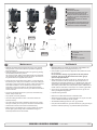
Installation and user's manual
N
Installasjons og brukermanual
is rd
th a
p bo
ee n
K al o
u
an
m
GB
SE 30/125 S
SE 40/125 S
SE 60/185 S
P.O. Box 519
N-1612 Fredrikstad
Norway
Tel: +47 69 30 00 60
Fax: +47 69 30 00 70
w w w. s i d e - p o w e r. c o m
s i d e p o w e r @ s l e i p n e r. n o
Made in Norway
!
SLEIPNER MOTOR AS
© Sleipner Motor AS 2007
Contents
GB
Installation instructions
Technical specifications.............................................................. 3
Planning & important precautions.............................................. 4
Tunnel installation
Positioning of the tunnel / thruster ............................................. 5
How to shape the tunnel ends.................................................... 6
How to prevent drag from tunnel installation.............................. 7
Possible tunnel installation in sailboats...................................... 8
Tunnel installation in a GRP boat............................................... 9
Thruster installation
Gearhouse and motorbracket................................................... 11
Oil tank & propeller.................................................................. 12
Electromotor............................................................................. 13
Electrical installation ................................................................ 14
Control panel and control-leads............................................... 15
Visual wiring diagram............................................................... 16
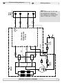
Technical wiring diagram ......................................................... 17
Checklist for control of the installation...................................... 18
User's manual
Important user precautions....................................................... 19
How to use Sidepower thrusters.............................................. 20
Maintenance & service............................................................. 21
Troubleshooting........................................................................ 22
Warranty statement ............................................................... 23
Spareparts list & drawing ..................................................... 24
Service centres ...................................................................... 28
DECLARATION OF CONFORMITY
We, Sleipner Motor AS
P.O. Box 519
N-1612 Fredrikstad, Norway
declare that this product with accompanying
standard remote control systems complies with
the essential health and safety requirements
according to the Directive 89/336/EEC of 23
May 1989 amended by 92/31/EEC and
93/68/EEC.
SE 60/185S-12V
Innhold
N
Installasjons instruksjoner
Tekniske spesifikasjoner..............................................................3
Planlegning og viktige forbehold.................................................4
Tunnel installasjon
Plassering av tunnel/thruster.......................................................5
Utforming av tunnelåpninger.......................................................6
Hvordan unngå turbulens rundt tunnelåpninger..........................7
Forslag til tunnelinstallasjon på seilbåt........................................8
Tunnel installasjon i glassfiberbåter............................................9
Thruster installasjon
Gearhus og motorbraket...........................................................11
Oljebeholder og propeller..........................................................12
Elektromotor..............................................................................13
Elektrisk installasjon..................................................................14
Kontrollpanel og kontrollkabler..................................................15
Koblingsskjema elektrisk...........................................................16
Koblingsskjema.........................................................................17
Sjekkpunktliste for kontroll av installasjon.................................18
Brukermanual
Viktige forbehold........................................................................19
Hvordan operere Sidepower thrustere......................................20
Vedlikehold og servise...............................................................21
Problemer og løsninger.............................................................22
Garantierklæring ....................................................................23
Reservedelsliste .....................................................................24
Servicesentere ....................................................................... 28
Samsvars erklæring
Sleipner Motor AS
Postboks 519
N-1612 Fredrikstad, Norge
Erklærer at dette produktet med tilhørende
standard kontrollsystemer er i samsvar med
helse, og sikkerhetskravene i henhold til Direktiv 89/336/EEC FRA 23 Mai 89, korrigert av
92/31/EEC og 93/68/EEC.
SE 30/125 S - SE 40/125 S - SE 60/185 S
1.0.0- 2007
Waterline
C
A
F
SP30S2i SE40/125S
SP40S2i SE60/185S
SP55S2i
SE30/125S
Thrust[kg]
[kg]
Thrust
A
[mm]
A [mm]
[mm]
BB[mm]
C
min. [mm]
Cmin. [mm]
[mm]
DD[mm]
D
recommended[mm]
[mm]
D recommended
E
min. [mm]
Emin. [mm]
max. [mm]
EEmax.
[mm]
Motor
output[kW]
[kW]
Motor output
Voltage
[V]
Voltage [V]
Weight[kg]
[kg]
Weight
30
30
125
125
234
234
125
125
92
92
184
184
44
55
1,5
1,5
12
12
9,5
9,5
40
40
125
125
234
234
125
125
92
92
184
184
44
55
2,2
2,2
12
12
10
10
55
60
185
185
265
265
150
150
117
117
234
234
44
66
3,1
3,1
12/24
12/24
16
16
IMPERIAL
IMPERIAL
METRIC
TRIC
METRIC
ME
min.: wwallthicknessofastandardSidepowertunnel
Note: EEmin.:
Note:
all thickness of a standard Sidepower tunnel
max.:
EEmax.:
mmaximumwallthicknesswhenusingotherGRP,
aximum wall thickness when using other GRP,
steeloraluminiumtunnels
steel
or aluminium tunnels
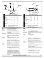
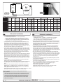
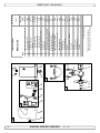
Technical specifications
specifications
Technical
GB
GB
Motor:
Motor:
Gearhouse:
Gearhouse:
Motor bracket:
Motor bracket:
Custom made reversible DC-motor.
Custom made reversible DC-motor.
Seawateresistant bronze. Ball bearing at
Seawateresistant
Ball bearing
at
propeller shaft andbronze.
combination
of ball bearing
propeller
andatcombination
of ball bearing
and slide shaft
bearing
driveshaft. Pre-filled
and
and
slide
at driveshaft. Pre-filled and
sealed
forbearing
life
sealed
for life
SP 30 S2i
/ SP 40 S2i / SP 55 S2i
Glass
composite material.
material.Brass
Brass
Glass fibre
fibre reinforced
reinforced composite
thread
thread inserts.
inserts.
Tunnel:
Tunnel:
Cross
rowing G.R.P
G.R.Ptunnel
tunnel
Cross spun
spun with
with rowing
Steel
aluminium tunnels
tunnels are
are available
availableon
on
Steel and
and aluminium
request.
request.
Propeller:
Propeller:
5-blade
skewback
design
"Q-prop"
propeller,
Symmetrical
4 blade
propeller,
fibreglass
reinforced
reinforced composite.
composite.
Batteries:
Batteries:
Minimum
battery capacity
capacity(cold
(cold
Minimum recommended
recommended battery
crank
by DIN/SAE
DIN/SAE standard)
standard)
crank capacity
capacity by
SE30/125S-12V
: 200
CCA
DIN/380
CCA
SAE
SP 30 S2i 12V : 200
CCA
DIN/380
CCA
SAE
SE40/125S-12V
: 300
CCA
DIN/570
CCA
SAE
SP 40 S2i 12V : 300
CCA
DIN/570
CCA
SAE
SE
: 350
CCA
DIN/665
CCA
SAE
SP 60/185S-12V
55 S2i12V : 350
CCA
DIN/665
CCA
SAE
SE 60/185S-24V
: 175
CCA
DIN/380
CCA
SAE
24V : 175
CCA
DIN/380
CCA
SAE
Max.
Max.use:
use:
S2
approx. 7-10%
7-10% within
withinaalimited
limited
S2 == 33 min.
min. or
or approx.
time
time frame.
frame.
Safety:
Safety:
Electronic
device protects
protectsagainst
against
Electronic time-lapse
time-lapse device
sudden
of drive
drive direction.
direction. Electric
Electricthermal
thermal
sudden change
change of
cut-off
in electromotor
electromotor protects
protectsagainst
against
cut-off switch
switch in
over
(auto reset
reset when
when electro
electromotor
motorcools
cools
over heating
heating (auto
down).
between electro-motor
electro-motorand
and
down). Shearpin
Shearpin between
driveshaft
electromotorand
andgear
gearsystem
system
driveshaft protects
protects electromotor
ifif propeller
gets jammed.
jammed.
propeller gets
IfIf original
panel is
is used,
used,the
thepanel
panel
original Sidepower
Sidepower panel
shuts
minutesafter
afterlast
lastuse.
use.
shuts off
off automatically
automatically 66 minutes
Integrated
monitors solenoids,
solenoids,
Integrated microprocessor
microprocessor monitors
reducing
and risk
risk of
of solenoid
solenoid lock-in.
lock-in.AutoAutoreducing wear
wear and
stop
in case
case of
of accidental
accidentalsolenoid
solenoid
stop of
of thruster
thruster in
lock-in
run signal
signal is
is continuous
continuousfor
formore
morethan
than
lock-in or
or ifif run
33 minutes.
minutes.
4
SP30S2i SE40/125S
SP40S2i SE60/185S
SP55S2i
SE30/125S
Thrust[lbs]
[lbs]
Thrust
A
[in]
A [in]
[in]
BB[in]
C
min. [in]
Cmin. [in]
[in]
DD[in]
D
recommended[mm]
[mm]
D recommended
E
min. [in]
Emin. [in]
max. [in]
EEmax.
[in]
Motor
output[Hp]
[Hp]
Motor output
Voltage
[V]
Voltage [V]
Weight[lbs]
[lbs]
Weight
66
66
4,92
4,92
9,2
9,2
4,92
4,92
3,6
3,6
7,25
7,25
0,16
0,16
0,20
0,20
22
12
12
21
21
88
88
4,92
4,92
9,2
9,2
4,92
4,92
3,6
3,6
7,25
7,25
0,16
0,16
0,20
0,20
33
12
12
22
22
121
132
7,28
7,28
10,4
10,4
5,91
5,91
4,6
4,6
9,2
9,2
0,16
0,16
0,24
0,24
44
12/24
12/24
35
35
min.:
wallthicknessofastandardSidepowertunnel
Note: EEmin.:
Note:
wall
thickness of a standard Sidepower tunnel
max.:
maximumwallthicknesswhenusingotherGRP,
EEmax.:
maximum
wall thickness when using other GRP,
steeloraluminiumtunnels
steel
or aluminium tunnels
DN
Tekniske
spesifikasjoner
Technische
Daten
Motor:
Gleichstrommotor
Getriebegeh.:
Motor:
Seewasserbeständige
Bronze.
Kugellager an der
Spesialutviklet reversibel
DC-motor.
Propellerachse, Kombination von Kugel- und Gleitlager
Sjøvannsbestandig bronsje. Kulelagre på propellaksel.
an der Antriebsachse.
Kule og glidelager komb. på drivaksel.
SP 30 Si / SP 40 Si / SP 55 S2i:
Glassfiberforsterket komposit materiale. Kobbertråd
Glasfiberverbundmaterial. Eingegossene
forsterket.
Gewindehülsen aus Messing.
Kryssvevet glassfiber.
Glasfibertunnel (Kreuzgewebe)
Aluminium og ståltunnel på forespørsel.
Stahl- & Aluminiumtunnel auf Anfrage.
5-blads skewback "Q-prop"i komposittmateriale.
Symmetrischer, 4 flügeliger Kaplanpropeller aus
Minimum anbefalt batteri størrelse.
Glasfiberverbundmaterial.
(Kaldstart kapasitet etter DIN/SAE std.)
Empfohlene mind. Batteriekapazität (Kaltstartkapazität
SE30/125S-12V : 200 CCA DIN/380 CCA SAE
nach DIN/SAE)
SE40/125S-12V : 300 CCA DIN/570 CCA SAE
SP 30 S2i 12V : 200 CCA DIN/380 CCA SAE
SE 60/185S-12V : 350 CCA DIN/665 CCA SAE
SP 40 S2i 12V : 300 CCA DIN/570 CCA SAE
SE 60/185S-24V : 175 CCA DIN/380 CCA SAE
SP 55 S2i 12V : 350 CCA DIN/665 CCA SAE
S2 = 3 min.
7-10%
innen en beg24VEller
: 175gjennomsnittlig
CCA DIN/380 CCA
SAE
renset tidsperiode.
S2 = 3 min. oder ca. 7-10% innerhalb eines beliebigen
Elektronisk tidsforsinkelse forhindrer motorskade ved
Zeitraumes.
rask retningsendring.
Elektronische
Zeitverzögerung
Schutz des
Motoren stanser
automatisk zum
ved overopphetning
(slår
Getriebes
bei plötzlichem
der Drehrich-tung.
seg automatisk
på etterWechsel
nedkjøling).
Elektrischer Thermoschalter zum Schutz des Motors
Brytepinne
mellom
drivaksel
og motor beskytter
gir
gegen
Überhitzung
(erneute
Betriebs-bereitschaft
nach
hvis propell blir blokkert.
Abkühlung).
Girhus:
Motorhalterung:
Motorbraket:
Tunnel:
Tunnel:
Propell:
Propeller:
Batterier:
Batterie:
Drift tid:
Betriebszeit:
Sikkerhet:
Sicherheit:
Om orginalt
Side-Power
panelund
blir brukt
så vil dette
Scherstift
zwischen
Elektromotor
Getriebe-achse
av automatisk
etter 6 minutter
etter
alsslås
Schutz,
wenn der Propeller
blockiert
ist. siste
Nachgang
der
trøsteren
ble brukt.
letzten
Benutzung
schaltet das Original Side-Power
Panel
automatisch
nach 6 Minuten
Der
integrierte
Integrerte
microprossessor
følerab.
hele
tiden
på Mikroprozessor
überwacht
Relais
reduziert
releet, reduserer
slitasjedas
og risk
for und
”heng”
på sowohl
Verschleiß,vilals
auch automatisk
Relaisblockade.
relé. Trøsteren
stoppe
etter Das
3 Bustrahlruder
automatisch
minutter omstoppt
det oppstår
”heng”bei
påRelais-Blockade,
relé, eller oder
Betrieb går
deskontinuerlig
Bugstrahlruders
von mehr als 3
ombei
trøsteren
i 3 minutter.
Minuten
SP 30 S2i
/ SP
40 S2Si/-SP
S2i S 3.71.0.0- 2006
SE 30/125
S - SE
40/125
SE 55
60/185
2007
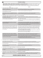
Planning and important precautions
GB
Prior to installation, it is important that the installer reads this guide to ensure necessary acquaintance with this product.
The thruster must NOT be installed in compartments that require ignition proof electric equipment. If necessary, make a separate
compartment.
The electromotor will generate some carbon dust so that any storage compartment must be separated from the thruster to prevent the stored items
from becoming dusty/dirty.
If you are installing the Sidepower in a small room /compartment, it should be ventilated to ensure cooling of the electromotor.
If the height in the room you are installing the Sidepower is limited, the Sidepower can be installed horizontally or at any angle in between.
-
If the electro motor is positioned more than 30o off vertical, it must be supported separately.
-
The electromotor must be handled carefully. Do not lift it by the internal connections/main terminals or put it down on the driveshaft.
-
Beware to keep installation within advised measurements. No part of the propeller or gearhouse must be outside the tunnel.
The electromotor, its components, contacts / plugs or other joints in the control cables must be mounted so that they will keep dry at all times.
We advice to paint the gearhouse and propellers with antifouling. PS! Do not paint the zinc anodes, sealings or propellershafts.
Do not finish the inside of the tunnel with a layer of gelcoat / topcoat or similar. It is only room for a thin layer of primer and two layers of
anti-fouling between the tunnel and the props.
With the boat on land, only run the thruster for a fraction of a second, as without resistance it will accelerate very fast to a damaging rpm.
Also, while the thruster is in air, make sure that the propellers have come to a complete stop before performing a directions change of the
thruster, as it might cause damage to the thruster.
This manual is intended to support educated/experienced staff and is therefore not sufficient in all details for the correct installation.
Don’t install the electromotor at close range to easily flammable objects as it will reach over 100°C before the temperature switch is
activated.
Do not store items close to the thruster motor as it gets hot as well as any loose items near the thruster motor can cause problems with electrical wiring coming loose and short-circuiting.
When installed in boats approved or classified according to international or special national rules, the installer is responsible for following the demands
in accordance with these regulations / classification rules. The instructions in this guide can not be guaranteed to comply with all
different regulations/classification rules.
These instructions are only general instruction. If you are not skilled to do this work, please contact professional installers for assistance.
NB! Faulty installation of the tunnel, thruster or panel will render all warranty given by Sleipner Motor AS void.
Viktige forholdsregler og planlegning
N
Før installasjon må instruksjonsmanualen leses gjennom, og bruker må gjøre seg kjent med produktet.
Thrusteren må ikke installeres i rom som der gnister og høy varme medfører brannfare.
Elektromotoren vil produsere karbon støv fra børstene under drift slik att en lagringsplass må fysisk avskilles fra thrusteren for å unngå att det man
lagrer blir støvete / møkkete.
Elektromotoren er avhengig av god kjøling, sørg derfor for ventilasjon eller god plass rundt motoren ved montering.
Elektromotoren kan monteres i alle vinkeler i fra vertikalt til horisontalt der hvor plassutnyttelsen krever det.
Hvis elektromotoren monteres i en vinkel på mer en 30o, må den støttes opp separat.
Elektromotoren må håndteres forsiktig. Den må ikke bæres etter kontaktpunktene, og motoren må ikke settes ned på drivakselen.
Følg de anbefalte målene som er oppgitt i manualen, propell eller girhus må ikke stikke ut av tunnelen.
Elektromotoren, tilhørende komponenter, kontakter eller åpne ledd i strømkabler må monteres så de ikke utsettes for vann.
Vi anbefaler å male girhuset med bunnstoff. PS sinkanoder, pakninger og propellaksel skal ikke påføres bunnstoff.
Ikke påfør gelcoat / topcoat eller lignende inne i tunellen. Det er bare plasee til ett lag primer og to lag bunnstoff mellom tunellen og propellene.
Når båten ligger på land har ikke elektromotoren den motstanden den har i vann. Motoren bruker derfor ekstremt kort tid før den oppnår ødeleggende
høyt turtall. Med båten på land, unngå hurtig bytte av driftsretning da det kan forårsake skade på truster.
Denne manualen er beregnet som støttemateriell for montører med erfaring / utdanning, og har derfor ikke all informasjon nødvendig for å oppnå en
korrekt installasjoner.
Installer ikke elektromotoren i nærheten av lett brennbart materiale, da motoren oppnår temperaturer over 100oC ved før den stopper automatisk.
Området intill thrusteren må ikke benyttes som lagringsplass da motoren vil bli varm samt att dette vil medføre en fare for att elektriske koblinger blir
løse eller kortslutter
I de tilfeller båter skal godkjennes eller klassifiseres i henhold til internasjonal, eller spesielle standarder, er montør ansvarlig for at de gjeldende lover
og regelverk følges. Sleipner Motor AS kan ikke garantere at instruksjonene i denne manualen er i henhold til alle gjeldende regelverk og standarder.
NB ! Ved feilaktig installasjon av panel, thruster eller tunnel frafaller all garanti stilt av Sleipner Motor AS.
SE 30/125 S - SE 40/125 S - SE 60/185 S
1.0.0- 2007
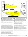
Fig. 1
Pivot
point
Fig. 3
A
B
B = 10,0m
A = 11,0m
min.
1/2Ø
Fig. 2
30 - 35 cm*
1/1 Ø
--
3/4Ø
-
Fig. 4
min.
1/3Ø
mi n
1/3 .
Ø
Ø
GB
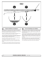
Positioning of the tunnel / thruster
The
bebe
asas
farfar
forward
as possible
(Fig.(Fig.
1) 1)
The Thruster
Thrustershould
should
forward
as possible
Because
around
thethe
boats
pivot
point,
it is it
very
Becauseofofthe
theleverage
leverageeffect
effect
around
boats
pivot
point,
is very
important
actual
effect
in the
boatboat
to get
as itfar
importantfor
forthe
thethrusters
thrusters
actual
effect
in the
to itget
asfor-ward
far foras
possible.
The relative
distancedistance
change from
the from
boatsthe
pivot
pointpivot
to the
ward
as possible.
The relative
change
boats
thruster
the change
of the
actual
thrustof
foractual
the boat.
point to will
thebe
thruster
will be
change
thrust for the boat.
Example:
Example:
A:
= 605kgm
torque
to rotate
the boat
A: 55kg
55kgthrust
thrustxx11m
11mleverage
leverage
= 605kgm
torque
to rotate
the boat
B:
= 550kgm
torque
to rotate
the boat
B: 55kg
55kgthrust
thrustxx10m
10mleverage
leverage
= 550kgm
torque
to rotate
the boat
In
more
thrust
to turn
the the
boatboat
around.
In position
positionAAyou
youwill
willget
get10%
10%
more
thrust
to turn
around.
The
bebe
placed
as as
deep
as possible
(Fig. (Fig.
2)
The thruster
thrustershould
should
placed
deep
as possible
2)
The
asas
deep
as as
possible
for two
reasons:
The tunnel
tunnelshould
shouldbebeplaced
placed
deep
possible
for two
reasons:
1.
down
air air
from
the the
surface
which
will will
1. So
So that
thatititdoes
doesnot
notsuck
suck
down
from
surface
which
destroy
destroythe
thethrust
thrustcompletely.
completely.
2.
a water
pressure
to get
maximum
2. To
To get
getas
ashigh
highasaspossible
possible
a water
pressure
to get
maximum
efficiency
efficiencyfrom
fromthe
thepropeller.
propeller.
Generally
tunnel
should
be be
a minimum
of ½of
x the
Generallythe
thetop
topofofthe
the
tunnel
should
a minimum
½ xtunnel
the
diameter
below the
waterline.
This is anThis
absolute
we rectunnel diameter
below
the waterline.
is anminimum
absoluteand
minimum
ommend
that it is at least
diameter
() below
the waterline.
and we recommend
that¾itxistunnel
at least
¾ x tunnel
diameter
(-) below
A
really
good distance
aboutdistance
1/1 x tunnel
diameter
below
the
the
waterline.
A reallyisgood
is about
1/1 x()
tunnel
diameter
waterline.
(--) below the waterline.
When
tunnel
30-35
cm*/1
feetfeet
below
the surface,
Whenyou
youget
getthe
thetop
topofofthe
the
tunnel
30-35
cm*/1
below
the
other
factors
should
be should
considered
more important,
moving the
surface,
other
factors
be considered
morei.e.
important,
i.e.thruster
furtherthe
forward.
moving
thruster further forward.
Optimal
Optimaltunnel
tunnellength
length
If the
the
friction
inside
willwill
reduce
the water
speed
the tunnel
tunnelgets
getstotolong,
long,
the
friction
inside
reduce
the water
and
thereby
the thrust.
speed
and thereby
the thrust.
If the
(normally
only
in the
bottom
section
of theoftunthe tunnel
tunnelgets
getstotoshort
short
(normally
only
in the
bottom
section
the
nel)
you you
can can
get cavitation
problems
as theas
water
notwill
have
time to
tunnel)
get cavitation
problems
the will
water
nothad
have
“straighten”
before reaching
the propeller
This (Fig.
cavitation
had time toitself
“straighten”
itself before
reaching(Fig.
the3&4).
propeller
3&4).
will
performance
as well
as creatingas
a lot
of as
noise.
Thisreduce
cavitation
will reduce
performance
well
creating a lot of
The
optimal tunnel length is 2 to 4 x tunnel diameter and you should avoid
noise.
tunnels
longertunnel
than 6length
to 7 times
diameter
as the
performance
The optimal
is 2 the
to 4tunnel
x tunnel
diameter
and
you should
reduction
is then
clearly
noticeable.
avoid tunnels
longer
than
6 to 7 times the tunnel diameter as the
performance reduction is then clearly noticeable.
10
N
D
Positionierung
Tunnel
/ Thruster
Plassering avvon
tunnel
og thruster
Tunnelen
bør plasseres
lengst
mulig
frem
i baugen
(Fig.
Tunnelplazierung
soweit
vorne
wie
möglich
(Fig.
1) 1)
For
oppnå
mest mulig
moment
rundt vom
båtens
dreiepunkt,
det meget
Um åeinen
möglichst
großen
Abstand
Drehpunkt
deserSchiffes
zu
viktig
å plassere
tunnelen
så langt
fremmeweit
somvorne
mulig.einzubauen.
Avstanden fra
erreichen,
ist der
Sidepower
möglichst
båtens
dreiepunkt til thruster
vil ha stor vom
betydning
på thrusterens
effekt.
Eine Vergrößerung
des Abstandes
Drehpunkt
des Schiffes
hat eine direkte Auswirkung auf die verfügbare Schubkraft.
Eks.:
A:
55kg skyvekraft
x 11m moment = 605kgm skyvekraft
Beispiel
:
B:
x x 10m
= 550kgm
skyvekraftdes Bootes
A: 55kg
55kgskyvekraft
Schubkraft
11mmoment
= 605kgm
zum Wenden
Posisjon
vil gi 10% mer
skyvekraft
til rotasjon.
B: 55kg A
Schubkraft
x 10m
= 550kgm
zum Wenden des Bootes
In Beispiel A stehen damit 10% mehr Schubkraft zur Verfügung.
Tunnelen skal plasseres dypest mulig (Fig. 2)
Tunnelen
skal so
plasseres
såmöglich
dypt sompositionieren
mulig av to grunner:
Den Tunnel
tief wie
(Fig. 2)
1.
SåTunnel
luft ikkeaus
suges
ned
i tunnelen
ødelegger
skyvekraften.
Den
zwei
Gründen
soå tief
wie möglich
positionieren:
2.
Ved å øke
vanntrykket
jobber propellen
merdie
effektivt.
1. Damit
nicht
Luft mitangesaugt
wird, die
Schubkraft
Hovedregelen
at tunnelen skal plasseres minimum ½ x tunnelen dia.
vollständigerherabsetzt.
under
Anbefalt dybde
minst ¾ x dia.zu
under
vannlinje
2. Umvannlinje.
einen möglichst
hohenerWasserdruck
erhalten,
um().
die Når
tunnelen
er plassert
33-35
cmPropellers
under vannlinjen
bør andre faktorer vurmaximale
Effizienz
des
erreichen.
deres
som viktigere,
å plassere
tunnelen
lengre
frem.TunnelDie Oberkante
desd.v.s.
Tunnels
muß mind.
einen
halben
durchmesser unterhalb der Wasserlinie liegen. Dieser Wert ist ein
Optimal
tunnel
lengdeBesser ist ein Wert von ca. ¾ des
absolutes
Minimum.
Dersom
tunellen blir for(-).
lang Optimal
vil friksjonen
i tunellen
reduser
Tunneldurchmessers
ist eine
Abstand
vonvannhastig1/1 x
heten
og derved effekten.
Tunneldurchmesser
(--) zur Wasserlinie.
Dersom
blir fordes
kortTunnels
(normalt30-35cm*
bare i nedre
del avunterhalb
tunellen) kan
Liegt dietunellen
Oberkante
/ 1fuß
der det
oppstå
kavitasjons
problemer
vannet ikke
har tid / av-stand
til å «rette
Wasserlinie,
können
anderedaFaktoren
berücksichtigt
werden.
opp strømningsretningen» før det treffer propellen (Fig. 3&4). Denne
kavitasjonen
vil redusere effekten og lage mye støy.
Optimale Tunnellänge
Den
optimale
lengden
er 2reduziert
til 4 ganger
tunell
diameteren og die
dersom
Bei einem
zutunell
langem
Tunnel
der
Reibungsverlust
tunellen
blir så mye som 6 und
til 7 ganger
diameteren
i lengde vil effekt tapet
Wassergeschwindigkeit
damit die
Schubkraft.
bli
merkbart.
Beiklart
einem
zu kurzem Tunnel (häufig im unteren Bereich des
Tunnels) können Kavitationsprobleme entstehen, da sich das
Wasser nicht gerade auszurichten kann (Fig. 3&4). Diese Kavitation ist leistungsreduzierend und kann starken Lärm verursachen.
Die optim. Tunnellänge ist das 2-4 fache des Tunneldurchmessers.
Tunnellängen von mehr als dem 6-7 fachen des Tunneldurchmessers sollten vermieden werden, da dadurch die Leistung
reduziert wird.
SE 30/125
S -/SE
S 1.0.0SP 75 Ti
SP40/125
95 Ti / SSP- SE
12560/185
Ti 2.5.12007 2007
Fig. 2
Fig. 1
R = 0,1 x D (10%)
D
R = 0,1 x D (10%)
/
Fig. 4
Fig. 3
GB
Tunnel ends
N
D
Formgebung
der Tunnelenden
Tunnelåpninger
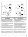
Rounded tunnel
ends
will maximize
thrust and
minimize
Rounded
tunnel
ends
will maximize
thrust
and noise.
minimize
noise.
Avrundede åpninger
vil minke støy,
og maksimere
effekt.
Abgerundete
Tunnelenden
erhöhen
die Schubkraft
und
reduzieren das Geräuschniveau.
much
as possible.rounding the tunnel connection to the hull-side as
We
recommend
The optimum
rounding has a radius of 10% of the tunnels diameter.
much
as possible.
The optimum rounding has a radius of 10% of the tunnels diameter.
Den Bereich
optimale Tunnelende
avrundingen har
en radie som
er Rumpfes
10% av tunnelens
diamDer
/ Außenseite
des
ist soweit
eter.
möglich
abzurunden. Der optimale Wert für den Radius dieser
Rundung beträgt 10% des Tunneldurchmessers.
Important advantages over sharp tunnel to hull connections are:
Vorteile gegenüber einer scharfen Tunnel / Rumpfverbindung sind:
The
cavitation
that tunnel
will come
sharp tunnel
endofwhen
water
1.
rounded
endfrom
will aprevent
creation
turbulence
cavitation
passes by fast,
thereby
preventing
a double
negative
impact
on
that will
come
from a sharp
tunnel
end when
water
passes
the thrustbyand
noise
level preventing
(Fig. 1 & 2).a double negative impact on
fast,
thereby
the
- The
turbulence
/ cavitation
blocks
thrust
and noise
level (Fig.
1 &the
2). outer area of the tunnel
- The
and thereby
reduces
the effective
tunnel
diameter
and
turbulence
/ cavitation
blocks
the outer
area
of thrust.
the tunnel
- and
The turbulence
/ cavitation
hits the propeller
and thereby
thereby reduces
the effective
tunnel diameter
andreduce
thrust.
- The
the propellers
performance
noise. and thereby reduce
turbulence
/ cavitationand
hitscreates
the propeller
the propellers performance and creates noise.
tasjon, noe somTunnelenden
vil oppstå vedverhindern
en installasjon
med skarpe/ kanter.
1. Abgerundete
Turbulenzen
Kavitation,
Turbulensen
forårsaker mer støy,
og begrenserauftreten.
skyvekraften.
wie
sie an scharfenkantigen
Tunnelenden
Damit
werden
- Turbulensen
kavitasjonen
blokkerer tunnelen
og svekker
skyvekrafzwei /negative
Auswirkungen
auf Schubkraft
und
ten.
Geräuschentwicklung
vermieden (Fig. 1 & 2).
- ITurbulenz
det kavitasjon
og turbulens
når propellen
påvirkes ytelsen
til denne
/ Kavitation
blockieren
den äußeren
Tunnelbereich.
og øker støyen.
Dadurch
werden effektiver Tunneldurchmesser und Schubkraft reduziert.
2. -En
avrundet
tunnelåpning
gjør trifft
ogsåauf
at thrusteren
sugerund
vannreduziert
langs
Die
Turbulenz
/ Kavitation
den Propeller
skroget
påEffektivität
båten. Dermed
et lavtrykk
som vil hjelpe å suge
dessen
und oppstår
führt zudet
zusätzl.
Geräuschentwicklung.
We recommend rounding the tunnel connection to the hull-side as
Important advantages over sharp tunnel to hull connections are:
1. The rounded tunnel end will prevent creation of turbulence
2. The curved tunnel end makes the thruster take water also from
The
alongcurved
the hull-side,
a vacuum
that willtake
suckwater
the boat
2.
tunnel creating
end makes
the thruster
also from
along
sideways
therebycreating
give additional
thrust
(Fig.
& 4). the boat
theand
hull-side,
a vacuum
that
will3suck
sideways
With a sharp
tunnel
end,give
the thruster
will thrust
be unable
and
thereby
additional
(Fig.to3take
& 4).water
With
from along
thetunnel
hull-side,
and
you
will notwill
getbe
theunable
desiredtovacuum
a sharp
end,
the
thruster
take water
from
and additional
This and
“free”you
additional
can
in optimal
along thethrust.
hull-side,
will notthrust
get the
desired
vacuum
and
installations
be as
muchThis
as 30
- 40%
of the total
thrust.
additional
thrust.
“free”
additional
thrust
can in optimal
installations be as much as 30 - 40% of the total thrust.
NB! A Sidepower thruster propeller does not cavitate at working
A
speed
so that all
cavitation
and cavitation
in the
will
NB!
Sidepower
thruster
propeller
does notnoise
cavitate
at tunnel
working
speed
be caused
by the
installation.
so that
all tunnel
cavitation
and cavitation noise in the tunnel will
NB! be
Even
if it is not
possible
to installation.
make the perfect rounding, it is very
caused
by the
tunnel
Even
important
to not
round
the tunnel
end asthe
much
as possible.
A it is very
NB!
if it is
possible
to make
perfect
rounding,
important
angled tunnel
to hull the
connection
will also
do much
of the same
to round
tunnel end
as much
as possible.
A
angled
job as a tunnel
rounded
(see page
20, Fig.
1b & 1d).
toconnection
hull connection
will also
do much
of the same
job as a rounded connection (see page 20, Fig. 1b & 1d).
12
Vi anbefaler å avrunde tunnelåpningene mest mulig.
Hvorfor er en avrundet tunnelåpning så viktig?
1. En avrundet tunnelåpning vil forhindre at det oppstår turbulens / kavi-
båten i dreieretningen. Med skarpe åpninger klarer ikke thrusteren å
suge vann langsermöglichen,
skroget, og lavtrykket
uteblir.entlang
Så myeder
somRumpf40% av
2. Abrundungen
daß Wasser
skyvekraften angesaugt
har blitt måltwerden
til å liggekann.
her på
noen installasjoner.
außenseite
Dadurch
entsteht ein
Vakuum ("zusätzliche" Schubkraft"), das das Schiff seitwärts
NB!
Propellene
Sidepower
thrustere kaviterer
ikke på
arbeids-hasbewegt
(Fig. til
3&
4). Bei scharfkantigen
Enden
kann
kein
tighet, entlang
så kavitasjon
og støy som oppstårangesaugt
som følge av
kavitasjon,
Wasser
der Rumpfaußenseite
werden,
skapes das
av tunnel
installasjonen.
wodurch
benötigte
Vakuum nicht zustande kommt.
NB!
SelvSchubkraft
der en perfekt
avrunding
ikke er mulig
er det viktig
av
Diese
kann
bei optimaler
Installation
bis zuå runde
30-40%
så mye
som mulig,
en tunnelåpning med skråkant vil ha
derkantene
absoluten
Schubkraft
betragen.
NB !
NB !
stor effekt fremfor en med skarpkant (se side 20, ill. 1b & 1d).
Sidepower Propeller sind so ausgelegt, daß sie nicht
kavitieren, sodaß die Geräuschentwicklung aufgrund von
Kavitation durch die Tunnelinstallation bedingt ist.
Ist eine optimale Abrundung nicht möglich, so sind die
Tunnelenden soweit möglich abzurunden. Angeschrägte
Tunnel / Rumpfverbindungen sind zu einem gewissen Grad
ebenfalls mit ähnlich positiven Auswirkungen wie eine
Abrundung verbunden (siehe Seite 20, Fig. 1b & 1d).
SE 30/125
- SE
60/185
S 1.0.0SP 75 STi- /SESP40/125
95 Ti /SSP
125
Ti 2.5.12007 2007
Fig. 1
/
GB
Fig. 2
Fig. 3
-
-
Prevent drag from tunnel
D
N
Optimaler
Strömungsverlauf
am Rumpf
Motstand
forårsaket av tunnel
A
in in
sailboats
or fast
powerboats
is that
A possible
possibleproblem
problem
sailboats
or fast
powerboats
is they
that get
theya get a
drag
ofof
thethe
tunnel,
as as
thisthis
becomes
a “flat”
area area
drag from
fromthe
theback
backface
face
tunnel,
becomes
a “flat”
facing
facingthe
thewater
waterflow
flow(Fig.
(Fig.1).1).
Et
mulig problem
seilbåter
ellerBooten
meget hurtiggående
båter er motstand
Segelboote
undfor
sehr
schnelle
können gelegentlich
durch
iauf
tunnelen.
Aktre endeFläche
på tunnelen
vil være auftreffendes
en liten loddrettWasser
flate mot
die rückseitige
des Tunnels
vannstrømmen
som(Fig.
skaper
gebremst werden
1).uønsket motstand.
This
with
thethe
thruster
spinning
(passive)
This can
canalso
alsocreate
createproblems
problems
with
thruster
spinning
(passive)
and
or or
driving
thethe
boat
withwith
water
being
and making
makingnoise
noisewhile
whilesailing
sailing
driving
boat
water
being
pushed
atat
high
speed.
pushedthrough
throughthe
thetunnel
tunnel
high
speed.
Denne
flatendazu
kan også
forårsake
problemer
med atdurch
vann føres
inn i tunDies kann
führen,
daß sich
der Thruster
den permanelen
under
seilas, eller kjøring
i høypassiv
fart ogzu
fårdrehen
da propellen
til å rotere,
nenten
Wasserdurchfluß
hörbar
beginnt.
dette skaper uønsket støy.
This
ways,
depending
on what
is is
This can
canbe
besolved
solvedinintwo
twodifferent
different
ways,
depending
on what
possible
possibleororeasier
easiertotodo.
do.
Det
er to mulige løsninger på problemet, avhengig av hva som er enklest
werden.
å få til på båten.
1.
normally
reduces
the drag
mostmost
is to make
1. The
Thebest
bestsolution
solutionwhich
which
normally
reduces
the drag
is to
a
recess
in the hull
at the
back
of the
tunnel.
Thereby
back face
make
a recess
in the
hull
at the
back
of the
tunnel.the
Thereby
the
is
gone
andisabout
theabout
drag (Fig.
2).drag
The depth
andThe
shape
of this
back
face
goneall
and
all the
(Fig. 2).
depth
and
recess
depend
on the
Basically
should
not seeyou
the back
shape will
of this
recess
will boat.
depend
on theyou
boat.
Basically
face
of the
when
standing
in front
of the
tunnel at
the
should
nottunnel
see the
back
face ofdirectly
the tunnel
when
standing
directly
angle
ofof
the
boats
centreline.
The angle
or down
backwards
in front
the
tunnel
at the angle
of theupboats
centreline.
Theof the
insert
depends
on theofhull
butthe
normally
it is angled
angleinupthe
or hull,
down
backwards
theshape,
insert in
hull, depends
on
slightly
because
of the water
flow on slightly
this areadown
of thebecause
hull.
the hulldown
shape,
but normally
it is angled
of
1. im
DenRumpfbereich
løsningen somhinter
vanligvis
reduserer
mest ervornimmt.
å lage
dem
Tunnel motstanden
eine Aussparung
en fordypning
i skroget
i aktre ende
av störender
tunnelåpningen.
loddrette
Dadurch
werden
Auftreffläche
und
EffektDen
eliminiert
flaten2).
vil da forsvinne og dermed motstanden. Hovedregelen å følge
(Fig.
er at bakkanten
tunnelen
ikke skal synes
når vom
man står
Tiefe
und Formavdieser
Aussparung
hängen
Bootrett
ab.foran
båten
å titter akterover
langs båten
utformingen
Die
Innenseite
des Tunnels
solltesenterlinje.
von vorneDybden,
prinzipiell
nicht
og vinkling
av fordypningen avhenger av båttypen, og hvordan vannet
sichtbar
sein.
følgermögliche
skroget, men
de fleste
båter vil være
tjent en
fordypning
Der
Winkel
der Aussparung
hängt
meist
von dersom
vinkler lett nedover
(Fig. 2).durch die Wasserströmung in diesem
Rumpfform
ab. Bedingt
2. The drag will also be reduced a lot, especially in fast power boats, by
a deflector
spoiler
in front
of the
tunnel. This
will power
push the
2. making
The drag
will also/ be
reduced
a lot,
especially
in fast
water
out from athe
hull so that
most in
of front
it passes
by tunnel.
the backThis
face
boats,flow
by making
deflector
/ spoiler
of the
of
tunnel
3).flow out from the hull so that most of it passes
willthe
push
the(Fig.
water
The
shape
and
size
this
deflector
by the
back
face
ofofthe
tunnel
(Fig.will
3).depend on the hull shape.
Basically
youand
should
back face
the tunnel
when
The shape
sizenot
of see
this the
deflector
will of
depend
on the
hullstanding
directly
front of the
at the
of the
boats
The
shape. in
Basically
youtunnel
should
not angle
see the
back
facecentreline.
of the tunnel
easiest
way of making
this
to let
parttunnel
of theat
tunnel
stick out
in the
when standing
directly
in is
front
ofathe
the angle
of the
lower
areaThe
of the
hole, and
as a this
support
a of
boatsforward
centreline.
easiest
wayuse
of this
making
is totoletmould
a part
soft
curve/spoiler
shape.
the tunnel
stick out
in the lower forward area of the hole, and use
2. Motstanden vil også reduseres av en spoiler i forkant av tunnelen.
Spoileren
fører det meste av vannstrømmen
rundt
forbi tunnelen.
2. Der
Geschwindigkeitsverlust
kann speziell
bei og
schnellen
Booten
Størrelsen
og Abweiser
utformingen
på spoileren
avhenger
av båten.
Hovedurch
einen
bzw.
Spoiler vor
dem Tunnel
deutlich
dregelen erwerden.
at bakkanten av tunnelen ikke skal synes når man står
reduziert
rett foran
båtenwird
å titter
akterover langs
senterlinje. Den
enkleste
Das
Wasser
so beeinflußt,
daßbåten
es größtenteils
an der
måten å lage
spoileren
pågeleitet
er å la tunnelen
stikke
frontalen
Fläche
vorbei
wird (Fig.
3). ut i forkant av tunnelen, ogund
forme
spoileren
mot denhängen
(Fig. 3). von der Rumpfform ab.
Form
Größe
des opp
Abweisers
the water flow on this area of the hull.
this as a support to mould a soft curve/spoiler shape.
Remember to still round the tunnel ends as much as possible to get
optimum
thruster
performance
minimum
noise.
Foras
more
Remember
to still
round the and
tunnel
ends as
much
possible to get
information
on howperformance
to practically do
this
see pagenoise.
20. For more
optimum thruster
and
minimum
information on how to practically do this see page 20.
14
Das Problem kann je nach Möglichkeit auf zwei Arten beseitigt
1. Der störende Effekt wird am deutlichsten reduziert, indem man
Bereich sollte dieser Winkel leicht nach unten gerichtet sein.
Prinzipiell sollte auch hier die Innenseite des Tunnels von vorne
Detnicht
er alltid
viktig åsondern
avrunde durch
tunnelåpningene
mestverdeckt
mulig for sein.
å motvirke
sichtbar,
den Abweiser
støyDieser
og for läßt
å få mest
mulig effekt
av thrusteren.
sich einfach
realisieren,
indem man den Tunnel ein
MerStück
informasjon
om Rumpf
dette påherausstehen
side 20.
aus dem
läßt und darauf einen
geschwungenen Abweiser / Spoiler formt.
Die Tunnelenden sind zur vollen Leistung und minimalen
Geräuschentwicklung des Thrusters weitgehend abzurunden.
Weitere Informationen siehe Seite 20.
SE 30/125
S -/SE
S 1.0.0SP 75 Ti
SP40/125
95 Ti / SSP- SE
12560/185
Ti 2.5.12007 2007
Fig. 1
-
Pos. A
Pos. B
/
-
Min
/
GB
Tunnel installation in sailboats
N
D
Tunnel
installasjon
på seilbåter
Installation
in Segelbooten
Many
racing
type
hullhull
which
means
that that
it is very
flat botManysailboats
sailboatshave
havea a
racing
type
which
means
it is very
tomed
and hasand
a very
in thedraft
bowin
section.
It issection.
therebyItvery
flat bottomed
hasshallow
a verydraft
shallow
the bow
is
difficult
to say
impossible
to fitimpossible
a tunnel thruster
usualthruster
way, at least
therebynot
very
difficult
not to say
to fit athe
tunnel
the
as
far forward
the as
hullfar
as forward
a thruster
(Fig.
1).
usual
way, at in
least
inshould
the hullbeas
a thruster
should be
Mange
seilbåtskrog
byggeteinen
for å oppnå
fart. De har auf,
brede
skrog
Segelboote
weisenerhäufig
Rumpfhøy
in Rennform
was
som
stikker
dypt Rumpf
i baugen.
gjør
det vanskelig
installere
einenikke
sehr
flachen
imSkrogtypen
Bugbereich
bedeutet.
Es istå daher
en
thrustertunnel
på vanlig
måte, spesielt
med tanke
pågewünschten
å plassere den
schwierig
oder fast
unmöglich,
den Tunnel
an der
langt
nok frem Stelle,
(Fig. 1).also möglichst weit vorne im Bug zu plazieren
(effektivsten)
However, it is possible to install a tunnel thruster in most sailboats, even
when
the hull
not directly
support
the fitting
of a in
tunnel.
However,
it isdoes
possible
to install
a tunnel
thruster
most sailboats,
Thrustertunneler kan allikevel installeres i de fleste seilbåter. Dette gjøres
ved
å la en ist
deles
av vielfach
tunnelenmöglich
stikke ut unter
i underkant
avBedingungen
skroget. Tunnelen
Trotzdem
diesen
eineer
sterk
nok til dette,
og thrusteren
blir wenn
plassert
lavTunnel
nok og damit
langt nok
fremme.
Bugschraube
einzubauen,
auch
der
nicht
völlig
This is done by fitting the tunnel halfway into and halfway under-neath the
existing
hull and
then strengthen
and smoothening
the waterunderflow by
This is done
by fitting
the tunnelit halfway
into and halfway
moulding
bulb around
/ underneath
the tunnel.
neath theaexisting
hull and
then strengthen
it and smoothening the
Dette gjøres ved at øvre halvdel av tunnelen støpes inn i skroget, tunnelen
ved å støpe
kul rundt tunnelen
og integriert,
jevne den ut
Derstyrkes
Tunneli underkant
wird zur Hälfte
in denenbestehenden
Rumpf
mest
mulig. Hälfte geht über diesen hinaus. Der Tunnel muß nur
die andere
This will allow installation in good position on the boat, maintaining the
reliability
and space
advantages
of aposition
tunnel thruster.
This will allow
installation
in good
on the boat, maintaining
Denne metoden brukes av noen av de helt største seilbåt-produsentene i
verden,
de viser
til at
den ikke girinutslag
på fart Position
under normal
seilas.
Dies erlaubt
eine
Installation
geeigneter
bei Nutzung
(Fig. 1).
even when the hull does not directly support the fitting of a tunnel.
water flow by moulding a bulb around / underneath the tunnel.
the reliability and space advantages of a tunnel thruster.
This installation is being used by some of the world’s largest sailboat
builders,
and has is
been
proven
give
little of
to the
no speed
loss
for normal
This installation
being
usedtoby
some
world’s
largest
sailboat
cruising.
builders, and has been proven to give little to no speed loss for
normal cruising.
This can also be a good installation method for flat bottomed barges to
avoid
extremely
tunnels
and hugemethod
oval tunnel
openings
in thebarges
hull.
This can
also belong
a good
installation
for flat
bottomed
to avoid extremely long tunnels and huge oval tunnel openings in the
hull.
16
(Fig. 1).
vom ursprünglichen Rumpf umgeben ist.
noch verstärkt und strömungsgünstig abgerundet werden.
der Zuverlässigkeits- und Platzvorteile einer Tunnelschraube.
Denne installasjonen kan også være gunstig for båter med flate bunner,
for
å unngå
ekstremt lange
og store
tunnelåpninger.
Diese
Installationsart
wirdtunneler
von einigen
derovale
weltweit
führenden
Segelboothersteller verwendet und führt meistens nur zu einem
äußerst geringen bzw. gar keinem Geschwindigkeitsverlust.
Diese Bauweise ist auch für Barkassen (z.B. Flußboote) mit
flachem Bug geeignet, um einen zu langen Tunnel und große
ovale Tunnelöffnungen im Rumpf zu vermeiden.
SE 30/125
- SE
60/185
S 1.0.0SP 75 STi- /SESP40/125
95 Ti /SSP
125
Ti 2.5.12007 2007
Fig. 1
R
D
Fig. 2
Fig. 3
GB
Tunnel installation
Fig. 4
N
Tunnel installering
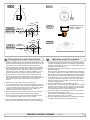
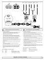
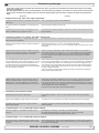
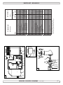
We recommend that a professional does the fibreglass fitting of the
tunnel. These instructions are only general, and do not explain in
any way the details of fibreglass work. Problems caused by faulty
installation of the tunnel, are the installers full responsibility.
Sleipner Motor anbefaler at innstøping av glassfibertunnelen utføres
av kyndig personell. Denne instruksjons manualen gir ikke detaljerte
opplysninger om glassfiberstøpning. Problemer som skyldes installering er installatørens fulle ansvar.
Find the position in the boat considering the information given earlier in
this manual and the applicable measurements for the thruster model you
are installing.
Bestem plassering av tunnelen ut i fra informasjonen gitt tidligere i manualen, og de angitte mål for thrusteren du skal installere.
Mark the centre of the tunnel on both sides. Drill a 6mm hole horizontally
in these marks (Fig. 1).
Bend a ø 5mm steel bar as shown with the “tip” bent back at the tunnel
radius and mark the circle for the tunnel opening (outside diameter of the
tunnel). Cut the hole with a jigsaw (Fig. 2).
Grind off the gelcoat and polyester so that you are down in the “real fibreglass” in an area of 12cm around the hole both inside and outside in the
hull to cast the tunnel to the hull (Fig. 3).
Insert the tunnel and mark its shape to fit the hull (Fig. 4). (if you are installing with a deflector/spoiler, leave a part or the tunnel of the front- and
underside of the tunnel to have a base for this (see page 20, Fig. 2). Cut
the tunnel ends to the desired shape and lightly sand its surface and
clean with acetone or similar where you are going to apply fibreglass.
NB! Do not cast/glass on the area were the thruster will be placed.
Merk av senter på tunnelen på babord og styrbord side. Bor et 6 m.m.
vannrett hull, på begge sider (Fig. 1).
Bøy til og tilpass en 5 m.m. stålstang, som vist på fig. 2 der den tilbakebøyde enden skal markere tunnelens radius. Stikk enden inn å marker
tunnelens ytre diameter, skjær ut hullet med en stikksag (Fig. 2).
Puss av gelcoat og polyester så glassfiberen ligger bar i et 12 cm stort
område rundt tunnel hullet. Dette må gjøres på innsiden og utsiden av
skroget, før tunnelen støpes fast i skroget (Fig. 3).
Sett inn tunnelen å marker hvor det skal kappes for å passe i skroget
(Fig. 4). Hvis det skal støpes en spoiler i forkant av tunnelen bør en del av
tunnelen stikke ut i for og underkant av skroget for å støpe spoileren mot
(Side 20, Fig. 2). Kapp tunnelen i ønsket størrelse. Slip lett med slipepapir, og vask med aceton der hvor det skal støpes med glassfiber.
NB ! Det må ikke støpes der hvor thrusteren skal monteres.
Then cast the tunnel to the inside of the hull, use at least 8 layers of 300 g
glass and resin, preferably alternating mat and rowing types of fibreglass
(see page 20, Fig. 1). If you are rounding the tunnel ends to the perfect
10% radius you may in some cases have to make further layers inside to
preserve the desired hull thickness.
Støp fast tunnelen først på innsiden av skroget, bruk minst 8 lag med 300
g Glassfibermatte, og polyester. Ved bruk av alternative materialer, glassfiber matter eller rovingtyper (Se s. 20, Fig. 1). Hvis tunnelåpningene
avrundes til den optimale 10% radius må ofte legge ekstra lag med polyester glassfibermatte på innersiden av tunnelen, for å oppnå riktig tykkelse i
forhold til skrogtykkelsen.
NB! Make sure that any gap between the tunnel and the hull are completely filled with resin/fibreglass. In areas where you can not access to
make normal layers of resin/fibreglass, a resin/ fibreglass mixture must be
filled in that area.
NB ! Forsikre deg om at overgangene mellom tunel og skrog er nøye
sammenstøpt. På steder en ikke kommer til med vanlige lag med polyester/glassfiber matte, sørg for og lage en blanding av polyester og glassfiber, som fylles i dette.
SE 30/125 S - SE 40/125 S - SE 60/185 S
1.0.0- 2007
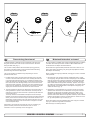
Fig. 1a
Fig. 1c
Fig. 1b
Fig. 1d
Fig. 1
Fig. 2
D
x
D
Tunnel installation
GB
Soften the
of of
10%
of the
tunnel
diameter
(Fig.(Fig.
1a) or
Soften
theedges
edgeswith
witha aradius
radius
10%
of the
tunnel
diameter
make
slope awith
a length
10-15%
the tunnel
diameter
1c). If
1a)
oramake
slope
with aoflength
of of
10-15%
of the
tunnel(Fig.
diameter
this is1c).
not possible,
at least
round at
theleast
tunnel
end as
as end
possible.
(Fig.
If this is not
possible,
round
themuch
tunnel
as
much
as possible.
We advice
to also cast two layers on the outside of the tunnel/hull for an
6-8cm area (Fig. 1c & 1d).
We advice to also cast two layers on the outside of the tunnel/hull for
Youarea
must6-8cm
apply topcoat/epoxy
an
(Fig. 1c & 1d).on the areas outside where you have
grounded or moulded to again make these waterproof.
You
apply topcoat/epoxy
on theare
areas
where
you have
NB! must
All original
Sidepower tunnels
fullyoutside
waterproof
when
grounded
or moulded
to again make these waterproof.
they are
delivered.
This means
that unless
you want,tunnels
becauseare
of special
reasons, to have
anNB!
All original
Sidepower
fully waterproof
when
other they
colourare
on it,
you do not have to apply topcoat or the several layers
delivered.
of primer that is necessary on the boats’ hull to make it water-resistant.
This
that unless
youone
want,
because
oftospecial
reasons,
to
Sandmeans
it very lightly
and apply
layer
of primer
make the
antifouling
have
sit. another colour on it, you do not have to apply topcoat or the
several layers of primer that is necessary on the boats’ hull to make
original
Sidepower tube itself is fully water-resistant without treatment
itThe
water
resistant.
except in the areas where you have bonded it to the hull.
Sand
it very lightly and
one layer
of areas
primerwhere
to make
Apply topcoat/epoxy
paintapply
and primer
on the
you the
have
antifouling
grounded orsit.
moulded as these areas give the water access to the hull
which normally is not waterproof without these applications outside.
The original Sidepower tube itself is fully water resistant without
PS! Avoid all casting where the motor-bracket is to be placed,
treatment
except in the areas where you have bonded it to the hull.
as this will cause misfit and possible failure of the
gearhouse.
Apply
topcoat/epoxy paint and primer on the areas where you have
grounded or moulded as these areas give the water access to the
hull which normally is not waterproof without these applications
outside.
N
D
Fig. 3
0,
1-
x
R = D x 0,1
5
D
R = D x 0,1
,15
-0
0,1
Tunnelinstallation
Tunnel
installering
Rund av tunnelendene
radius
10% av
tunneldiameter
(Fig. 1a),
Runden
Sie die Kantenmed
miten
einem
Radius
(10%
des Tunneldurcheller lag enab
skråkant
10-15%
av tunneldiameter
1c). Der
messers)
(Fig. 1a)
oder machen
Sie eine (Fig.
Schräge
mit dette
einer ikke er
mulig skal
kantene
rundes av mest mulig.(Fig. 1c). Ist beides
Länge
vontunnel
10-15%
des Tunneldurchmessers
nicht
möglich,
sind die
Tunnelenden
soweit möglich
Vi anbefaler
å støpe
to lag
utenpå tunnellavrundingen
ogabzurunden.
over et område
på 6-8cm
(Fig. 1c & 1d).
Auf
der Außenseite
zusätzlich zwei Schichten im Bereich Rumpf /
Tunnel
auf
einer
Fläche
von 6-8cm
auftragender
(Fig.
1d).
Gelcoat eller lignende må påføres
på områdene
det 1c
har&blitt
pusset
eller støptauf
forden
å gjøre
glassfiberen
vanntett. oder laminierten Flächen
Danach
äußeren,
angeschliffenen
Gelcoat/Topcoat/Epoxy
zur
wasserdichten
Versiegelung
aufbringen.
NB ! Alle originale Sidepower tunneler er vanntette
ved levering!
NB
! Original
Sidepower
tunnelfarge
sinderindet
ausgeliefertem
Så fremt
man ikke
ønsker en annen
ikke nødvendig å påføre
Zustand
wasserdicht.
Gelkoat,
Topkoatabsolut
og flere lag
med primer for å gjøre tunnelen vanntett.
Wird
nicht eine
spezielle
Farbeog
gewünscht,
sind for
keinerlei
Puss tunnelen
med
fint slipepapir
påfør et lagso
primer
å få bunnstoff
Gelcoat,
til å sitte. Topcoat oder Primer nötig, die ansonsten zur
Wasserdichtigkeit benötigt werden.
Sidepowertunnelen er helt vanntett uten behandling med unntak av de
Empfehlenswert
iststøpt
ein leichtes
anschleifen und aufbringen einer
områder det som er
fast i skroget.
Primerschicht zur besseren Haftung des Antifouling.
Påfør Gelcoat/Topcoat/epoxy og primer på de områder som er pusset ned
Original
Sidepowertunnel
auch
ohnemed
Behandlung
absolut
eller støpt.
Vann skal ikke hasind
direkte
kontakt
glassfiberen
i skroget
wasserdicht.
fordi dette normalt ikke er vanntett.
Auf
oder
angeschliffenen
Flächen
ist Gelcoat
/ Topcoat
/
PS !laminierten
Det må ikke
støpes
der brakketen
til thrusteren
skal
stå. PassEpoxyformen
und Primer
aufzubringen,
Bereichebraket
ohne kan forårer nøyaktig
tilpasset,da
ogdiese
en feilplassert
entsprechende
nicht wasserdicht sind.
sake sviktBehandlung
i girhus.
PS ! Im Bereich der Motorhalterung darf nicht laminiert werden, da dies zu Ungenauigkeiten bei der Montage und
damit einem möglichen Getriebeschaden führen kann.
PS! Avoid all casting where the motor-bracket is to be
placed, as this will cause misfit and possible failure of
the gearhouse.
10
20
0,
1
SE 30/125
- SE
40/125
SP 30 SS2i
/ SP
40 S2Si/- SE
SP60/185
55 Si S3.5 -1.0.020052007
Port
Starboard
Fig. 5
BOW
BOATS
CENTRELINE
TUNNELS
Fig. 2
SP30S2i CENTRELINE
TUNNELS
Fig. 2
SP40S2i
Ø 8,5mm
CENTRELINE
SP30S2i
0,33"
SP40S2i
Ø 8,5mm
TUNNELS
Fig. 2
0,33"
CENTRELINE
SP30S2i
SP40S2i
TUNNELS
Fig.
Ø 8,5mm
Fig.22
0,33"
CENTRELINE
SE30/125S
SP30S2i
SE40/125S
SP40S2i
Ø 8,5mm
TUNNELS
0,33"
Fig. 3
CENTRELINE
SP55Si
TUNNELS
Fig. 3
Ø 8,5mm
CENTRELINE
0,33"
SP55Si
O IL
AR
GE
90
EP
Fig. 5
Fig. 5
BOW
Ø 27,5mm
20,5mm
BOW
1,08"
0,81"BOATS
CENTRELINE Ø 27,5mm
20,5mm
1,08"
0,81"
BOW
Fig. 5
Fig. 6
Fig.Fig.
4 6
3
4
Fig. 6
CENTRELINE
Ø 27,5mm
BOW
1,08"
BOATS
CENTRELINE
BOW
Ø 28,5mm
23,0mm
Ø 8,5mm
TUNNELS
1,1"
BOATS0,91"
0,33"
Fig. 3
CENTRELINE
CENTRELINE
Ø 28,5mm
23,0mm
SP55Si
1,1"
0,91"
TUNNELS
Ø 8,5mm
GB Fig.
Fig. 23 CENTRELINE
0,33"
Ø 28,5mm
SP55S2i
23,0mm
SE60/185S
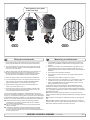
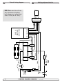
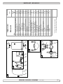
1.GB
Mark the centreline ofØthe
tunnel1,1"
and the boats 0,91"
centreline. The
8,5mm
Fitting gearhouse and motor bracket
A
A
Bolt tightening forces (2x):
DIN 931 - M 8x55 A2 =
Bolt
tightening
forces (2x):
17 Nm
(12,4 lb/ft)
DIN 931 - M 8x55 A2 =
17 Nm (12,4 lb/ft)
Bolt tightening forces (2x):
DIN 931 - M 8x55 A2 =
17
Nm
(12,4 lb/ft)
Bolt
tightening
forces (2x):
A
A
BOATS
Ø 27,5mmBOW
CENTRELINE
20,5mm
1,08"
0,81"
BOATS
20,5mm
0,81"
2
BOW
BOATS
CENTRELINE
BOATS
CENTRELINE
1
R
Fig. 1
2
NE
Starboard
3
4
3
4
EIP
Port
R
Fig. 1
O IL
AR 1
90
EP
O IL
AR
GE
90
EP
GE
SL
SP55Si
only
Fig. 4
SP55Si
Fig.only
3
Starboard
NE
Port
Fig. 6
Fig. 7
DIN 931 - M 8x55 A2 =
17 Nm (12,4 lb/ft)
Fig.Fig.
5 7
D
Fig. 7
Getriebe und Motorhalterung
Fitting gearhouse and motor bracket
Getriebe
und
Motorhalterung
1. DDie Mittellinie
von Tunnel
und
Boot markieren. Damit Schubgearhouse and propeller
must be fitted as shown above for the
0,33"
richtung und Kontrollpanel übereinstimmen, Getriebege-häuse
direction
to correspond
with
thethe
control
(Fig. 1).
Ø 28,5mm
7
Propeller
wie oben
gezeigt
einbauen
(Fig.1).
23,0mm
1. thrust
Mark the
centreline
of the tunnel
and
boatspanel
centreline.
The
1. und
DieFig.
Mittellinie
von
Tunnel
und Boot
markieren.
Damit Schub1,1"
0,91"
gearhouse
and
propeller mustand
be fitted
as shown
above for the
richtung
und
Kontrollpanel
übereinstimmen,
Getriebege-häuse
GB
D
Fitting
gearhouse
motor
bracket
Getriebe
und
Motorhalterung
2.
Die
Löcher
mit
der
Dichtung
(A)
markieren.
Maße
überprüfen!
2. thrust
Use the
gasket to
(A)correspond
to mark thewith
centre
the holes
double
direction
the of
control
paneland
(Fig.
1).
und
wie oben
(Fig.1).
NB !Propeller
Der Thruster
sollte gezeigt
mit demeinbauen
Bolzenloch
als Zentrum
check the measurements. NB! The thruster should be placed
withthe
thecentreline
bolt hole
the
centre
(Fig.the
2&3).
Allholes
holesand
must
be inplaziert
werden
(Fig.
2&3).
dermarkieren.
Abstand zwischen
Propeller
DieMittellinie
Löcher
mit
Dichtung
(A)
Maße
1.2.Mark
oftothe
tunnel
centreline.
The
1.2. Die
vonder
Tunnel
undDa
Boot
markieren.
Damitüberprüfen!
SchubUse
the
gasket
(A)as
mark
the and
centre
ofboats
the
double
GB
D
lineFitting
with
tunnels’
centreline
for
precise
installation,
asthe
the
gearhouse
motor
bracket
Getriebe
und
Motorhalterung
und!Tunnel
minimal
ist,
müssen
für
eine präzise
Installation alle
gearhouse
and
propeller
must
beand
fitted
as
shown
above
NB
Der
Thruster
sollte
mit
dem
Bolzenloch
als Zentrum
check
thethe
measurements.
NB!
The
thruster
should
be for
placed
richtung
und
Kontrollpanel
übereinstimmen,
Getriebege-häuse
clearance
between
the
propeller
and
tunnel
is minimal.
Löcher
auf
der
des
liegen.
thrust
direction
to correspond
with(Fig.
the the
control
(Fig.
1).be inthe bolt
hole
as
the
centre
2&3).
Allpanel
holes
must
plaziert
werden
(Fig.
DaTunnels
der Abstand
zwischen Propeller
Propeller
wieMittellinie
oben2&3).
gezeigt
einbauen
(Fig.1).
GBwith
Nund
Montering
av
girhus
og
brakett
Fitting
gearhouse
and
motor
bracket
line
with
the
tunnels’
centreline
for
precise
installation,
as the
1.
Mark
the
centreline
of
the
tunnel
and
the
boats
centreline.
The
und
Tunnel
minimal
ist,
müssen
für
eine
präzise
Installation
1.
Die
Mittellinie
von
Tunnel
und
Boot
markieren.
Damit
Schub3.
Im
Bereich
der
Motorhalterung
darf
kein
Laminat
dem alle
There
be noto
casting
where
the the
motor
bracket
is double
to be
2. Die Löcher mit der Dichtung (A) markieren. Maße auf
überprüfen!
2.3.Use
the must
gasket
mark
the
centre
of
the
holes
clearance
between
the
propeller
tunnel
is and
minimal.
gearhouse
and(A)
propeller
must
beand
fitted
shown
above
for The
the
Löcher
auf
des
Tunnels
liegen.
richtung
undder
Kontrollpanel
übereinstimmen,
Getriebege-häuse
Tunnel
sein,
daMittellinie
dies
zumit
einem
Getriebeschaden
führen kann.
placed,
as
this
will
cause NB!
possible
failureasofshould
the gearhouse.
NB
!
Der
Thruster
sollte
dem
Bolzenloch
als
Zentrum
check
the
measurements.
The
thruster
be
placed
1. Mark
the
centreline
of
tunnel
and
the
boats
centreline.
The
1. For
åPropeller
plasserewie
girhuset
måeinbauen
du først (Fig.1).
markere tunnelens,
thrust
direction
to correspond
with
thetunnel,
control
(Fig. is
1).not
und
oben riktig
gezeigt
motor
fit the
steady
on the
the
if panel
the
tunnel
Liegt
die
Motorhalterung
nicht
eben
auf dem
Tunnel
auf,
so
the bracket
bolt and
hole
ascasting
the
centre
(Fig.
2&3).
Allshown
holes
must
in-the
3. plaziert
Imbåtens
Bereich
der(Fig.
Motorhalterung
darf
kein
Laminat
aufPropeller
demmå
werden
2&3).
Da der
Abstand
zwischen
3.with
There
must
bemust
no
where
motor
bracket
is to be
gearhouse
propeller
must
be fitted
as
above
for
og
senterlinje
på tunnelen.
Propellen
og girhuset
smooth,
all
bumps
or
uneven
parts
must
be
grinded
smooth.
sindTunnel
sämtliche
Unebenheiten
in diesem
Bereich
abzuschleifen.
with
the
tunnels’
centreline
precise
installation,
asdouble
the1).
Tunnel
sein,
da
dies
zu
einem
Getriebeschaden
führen
kann.
placed,
as
this
will
cause
possible
failure
of
the
gearhouse.
The
2. und
Die
Löcher
mit
der
Dichtung
(A)
markieren.
Maße
überprüfen!
minimal
ist,
müssen
für
eine
präzise
Installation
alle
thrust
direction
to
with
the of
control
panel
(Fig.
2.line
Use
the
gasket
(A)correspond
to
mark
thefor
centre
the
holes
and
plasseres i henhold til fig. 1 ovenfor for at styreretning og kjøclearance
between
thefitpropeller
and
the
tunnelshould
minimal.
motor the
bracket
must
steady
on
the
tunnel,
ifisthe
tunnel
is not
Liegt
die
Motorhalterung
nicht
eben
auf
demals
Tunnel
auf, so
NB
Thruster
sollte
mit
dem
Bolzenloch
Zentrum
measurements.
NB!
The
thruster
be placed
aufskal
der korrespondere
Mittellinie
des
Tunnels
liegen.
4. Löcher
Erst! Der
das
Hauptloch,
dann
die
beiden
Bolzenlöcher
bohren.
4. check
Drill
the
main-hole
and
then
the
two
screw-holes.
reretning
smooth,
all bumps
uneven
parts
must
smooth.
2. Use
the
(A)asor
tothe
mark
the
centre
of be
the
holes and
double
with
the gasket
bolt
hole
centre
(Fig.
2&3).
Allgrinded
must
be insind sämtliche
diesem
Bereich
abzuschleifen.
plaziert
werdenUnebenheiten
(Fig. 2&3). Dainder
Abstand
zwischen
Propeller
3.
Bereich
der Motorhalterung
darf kein
Laminat
auf
dem
3. There
must
betunnels’
no casting
where
theprecise
motor
bracket
is to
be
5. Im
Das
Getriebegehäuse
mit
Getriebeöl
EP90
durch
die
Öffnung
2.
Bruk
pakningen
til å markere
midten
av
hullet
(A)
og
for
å dobcheck
the
measurements.
NB!
The
thruster
should
be
placed
line
with
the
centreline
for
installation,
as
the
und
Tunnel
minimal
ist,
müssen
für eine
präzise
Installation
alle
5.
For
SP55Si,
pre-fill
the
gearhouse
with
gear
oil
type
EP90
4.
Erst
das
Hauptloch,
dann
die
beiden
Bolzenlöcher
bohren.
Tunnel
sein,
da
dies
zu
einem
Getriebeschaden
führen
kann.
placed,
as
this
will
cause
possible
failure
of
the
gearhouse.
The
4.with
Drillthe
the bolt
main-hole
and
then
the (Fig.
two
screw-holes.
der
Ölablaßschraube
(4)
befüllen.
Kupferdichtung
(3)
einsetzen.
beltsjekke
målene.
hole
as
the
centre
2).
All
holes
must
be
inclearance
between
the
propeller
and
the
tunnel
is
minimal.
Löcher
auf
der
Mittellinie
des
Tunnels
liegen.
through
the
oil
drain
screw
(4).
Make
sure
to
get
the
copper
motor
bracket
must fit centreline
steady on for
the precise
tunnel, ifinstallation,
the tunnel is
Liegt
die
Motorhalterung
nicht
eben
dem Tunnel
auf,
so
line
with
theon
tunnels’
asnot
the
Das
Getriebegehäuse
mit
Getriebeöl
EP90
durch
Öffnung
5.
NB
! Thrusteren
skal plasseres
medauf
boltehullet
somdie
senterlingasket
(3)
again
(SP55Si
only).must
6. sind
Das
Getriebegehäuse
(ohne
unter
Verwendung
all
bumps
uneven
parts
betunnel
grinded
smooth.
5.smooth,
For
SP55Si,
pre-fill
the
gearhouse
with
oil type
3.
Im
Bereich
der
Motorhalterung
darf
kein
Laminat
aufeinsetzen.
dem der
sämtliche
Unebenheiten
in Propeller)
diesem
Bereich
abzuschleifen.
clearance
between
the
propeller
and
thegear
is minimal.
3.
There
must
be
noor
casting
where
the
motor
bracket
isEP90
to be
der
Ölablaßschraube
(4)
befüllen.
Kupferdichtung
(3)
jen
i
midten
av
båten
(Fig.
2).
Alle
hull
må
være
på
tunnelens
Dichtung
in den
Tunnel
einpassen.
Den Propeller
auf die
throughas
thethis
oil drain
screwpossible
(4). Make
sureoftothe
getgearhouse.
the copper The
Tunnel
sein,
da dies
zu einem
Getriebeschaden
führen
kann.
willincause
failure
6. placed,
Try
themain-hole
lower-unit
the
tunnel
(without
the propeller)
by using the 4. Erst
Hauptloch,
dann
die sich
beiden
Bolzenlöcher
bohren.
for å får
til
en(ohne
presis
installasjon.
skyldes
at
4.
the
then
theonly).
two
screw-holes.
Achse
stecken;
dieser
muß
freiauf
bewegen
lassen
und
gasket
(3)
on
(SP55Si
6. senterlinje
Dasdas
Getriebegehäuse
Propeller)
unterDette
Verwendung
der
3. Drill
There
beagain
noand
casting
where
the
motor bracket
is sure
toisbenot
motor
bracket
must
fit
steady
on
the
tunnel,
if to
themake
tunnel
Liegt
die
Motorhalterung
nicht
eben
dem
Tunnel
auf,
sojedes
sind
gasketmust
inside
the
tunnel.
Try
on
the
propeller
it is in
det
er
meget
liten
klaring
mellom
tunnelveggen
og
propellen.
Propellerblatt
muß
den
gleichen
Abstand
zum
Tunnel
placed,
as
this
will
cause
possible
failure
of
the
gearhouse.
smooth,
all
bumps
or
uneven
parts
must
be
grinded
smooth.
Dichtung
in
den
Tunnel
einpassen.
Den
Propeller
auf
die
5.
Das
Getriebegehäuse
mit
Getriebeöl
EP90
durch
die
Öffnung
sämtliche
Unebenheiten
in
diesem
Bereich
abzuschleifen.
the
middle
of
the tunnel
and turns
freely
with
the
same
clearing
5.6.For
SP55Si,
pre-fill
the
gearhouse
with
gear
oil
type
EP90
Try
the
lower-unit
in
the
tunnel
(without
the
propeller)
by
using
the
aufweisen.
etwas
The
motor
bracket
must
fit steady
on
the tunnel,
if the tunnel
Tunnelen
måIsthadie
enTunnelinnenseite
jevn
overflate
derungleichmäßig,
braketenlassen
skal
festes,
Achse
stecken;
dieser
muß
sichKupferdichtung
frei
bewegen
und jedes
der
Ölablaßschraube
(4) befüllen.
(3)
einsetzen.
from
each
blade
totunnel.
the tunnel.
Use
sealant
e.g.
Sikaflex
to it isisin 3.
oil
drain
screw
(4).the
Make
sure
to get
copper
4. all
Erst
dasevt
Hauptloch,
dann
die
beiden
Bolzenlöcher
bohren.
gasket
inside
the
Try
on
the
propeller
tothe
make
sure
not
smooth,
all
bumps
or
uneven
parts
must
be
grinded
4.through
Drill
thethe
main-hole
and
then
two
screw-holes.
Sikaflex
o.ä.glassfiber
auf-tragen,
damit
keine
undichte
Stelle
auftritt.
støp,
eller
epoxy
rester
må
pusses
ned
så
Propellerblatt
muß
den
gleichen
Abstand
zum
Tunnel
ensure
that
no
leakages
occur.
gasket
(3) onofagain
(SP55Si
the middle
the tunnel
andonly).
turns freely with the same clearing
6. Das
Getriebegehäuse
(ohne
Propeller)
unter
Verwendung
der
smooth.
PS
!Getriebegehäuse
Diepasser
Durchgänge
für
das
Öl (2)Ujevnheter
von
Dichtmasse
freihalten.
braketen
jevnt
på
tunnelen.
her viletwas
kunne
aufweisen.
Ist
die
Tunnelinnenseite
ungleichmäßig,
5.
Das
(ohne
Propeller)
unter
Verwendung
der
PS!
Make
sure
that
no
sealant
gets
in
to
the
oil-holes
(2).
fromthe
each
blade tointhe
sealant
e.g. Sikaflex
Dichtung
in
den
Tunnel
einpassen.
Den
Propeller
auf auftritt.
die
5. Try
lower-unit
thetunnel.
tunnel Use
(without
the propeller)
by to
using
resultere
i
skade
girhuset.
Sikaflex
o.ä.
auf-tragen,
damit
keine
undichte
Stelle
Dichtung
in
den
Tunnel
einpassen.
Den
Propeller
auf
die
Achse
6.
the
lower-unit
inthe
the tunnel.
tunnel
(without
thepropeller
propeller)
by
using
theit
7. Achse
Etwasstecken;
Öl oder dieser
Fett auf
die
O-ringe
der
Motorhalterung
geben,
ensure
thatinside
no leakages
occur.
4.7.Try
Drill
the
main-hole
and
then
the
two
screw-holes.
the
gasket
Try
on
the
to
make
sure
muß sich frei bewegen lassen und jedes
SP55SI
only,
if the
unit
is
installed
inina to
horizontal
angle,
the
feed
PS
! Die
Durchgänge
für
das
Ölbeschädigt
(2) vonlassen
Dichtmasse
freihalten.
stecken;
muß sich
bewegen
und jedes
gasket
inside
the
tunnel.
Try
onand
the
propeller
make
it is
in
4. Propellerblatt
Bor
to dieser
boltehullene,
ogfrei
hovedhullet
girhuset.
PS!
sure
that
notunnel
sealant
gets
thetooil-holes
(2).
da de
diese
sonst
beim
werden
is inMake
the
middle
of
the
turns
freely
with
thesure
same
muß
denMontieren
gleichen
Abstandtil zum
Tunnelkönnen.
pipe
in
the
motor
bracket
has
always
towith
show
upwards
to ensure
Propellerblatt
muß
den
gleichen
Abstand
zum Tunnel
the
middle
of
the
tunnel
and
turns
freely
the
same
clearing
5. Try
the
lower-unit
in
the
tunnel
(without
the
propeller)
by
using
clearing
from
each
blade
to
the
tunnel.
Use
sealant
e.g.
Sikaflex
5.
Prøv
girhuset
i
tunnelen
sammen
med
pakning
1m.m.
Monter
7.
Etwas
Öl
oder
Fett
auf
die
O-ringe
der
Motorhalterung
geben,
aufweisen.
Ist
die
Tunnelinnenseite
ungleichmäßig,
etwas
that
the oil
flows
freely
into
the
gearhouse.
8. aufweisen.
Das Getriebegehäuse
durch das Hauptloch
im Tunnel
führen
each
blade
to
the
tunnel.
Use
sealant
e.g. Sikaflex
tothe sure
Ist die
Tunnelinnenseite
ungleichmäßig,
etwas
7.from
SP55SI
only,
if no
the
unit
is installed
in the
a horizontal
angle,
feed
the
gasket
inside
the
tunnel.
Try on
propeller
to make
to ensure
that
leakages
occur.
propell
åo.ä.
sjekk
at
den
erMotorhalterung
i midten
avundichte
tunnelen.
Hvis auftritt.
tunnelen
da
diese
sonst
beim
Montieren
beschädigt
werden
können.
Sikaflex
auf-tragen,
damit
keine
Stelle
und
vorsichtig
mit
der
zusammenschieben.
ensure
that
no
leakages
occur.
pipe
inthe
themiddle
motor bracket
has always
to show
upwards
tosame
ensure
Sikaflex
o.ä.
auf-tragen,
damit
keine
undichte
Stelle
auftritt.
it
is
in
of
the
tunnel
and
turns
freely
with
the
ikke
har
en jevn overflate
så Öl
kan
eller
lignende
tet8. that
Make
sure
thatthat
there
is
some
oil
oringrease
on
the O-rings
PS
! Die
Durchgänge
fürdurch
das
(2)Sikafleks,
von Dichtmasse
freihalten.
Make
sure
nothrough
sealant
gets
tohole
the
oil-holes
(2). and
the
flows
freely
into
the
gearhouse.
8.
Das
Getriebegehäuse
das
Hauptloch
im Tunnel
führen
clearing
from
each
the
tunnel.
Use
6.PS!
Push
theoil
gearhouse
the
main
insealant
the tunnel
9. ningsmateriale
Das Getriebegehäuse
Getriebegehäuse
undådie
Motorhalterung
Hilfe führen
der
bei(SP55Si
only)
in theblade
motortobracket
before
mounting
it e.g.
together
brukes
for
sikre
mot lekkasje.
6.
Das
durch
das
Hauptloch
immit
Tunnel
Sikaflex
to
ensure
that
no
leakages
occur.
push
the
gearhouse
and
motor-bracket
gently
together.
und
vorsichtig
mit
der
Motorhalterung
zusammenschieben.
7.
Etwas
Öl
oder
Fett
auf
die
O-ringe
der
Motorhalterung
geben,
den vorsichtig
Bolzen verschrauben
(Anzugsmoment
17 Nm / 12,4 lb/ft).
with
gearhouse.
und
mit der hovedhullet
Motorhalterung
zusammenschieben.
7.8.SP55SI
only,
if the
unit is
is some
installed
in a
horizontal
angle,
the feed
Makethe
sure
that
there
oil or
grease
on the
O-rings
6. da
Før
girhuset
gjennom
i
tunnelen
og
monter
bradiese
sonst beim Montieren
beschädigt
werden
können.
9.
Das
Getriebegehäuse
und sammen.
die
Motorhalterung
mit Hilfe
der beipipe
inthe
the
motor
has
always
to show
upwards
to
ensure
(SP55Si
the and
motor
before
mounting
itwith
together
10.ketten
Wird
die
Einheit außerhalb
derMotorhalterung
Horizontalen eingebaut,
6.7.
Push
gearhouse
through
the main
main
hole
thetunnel
tunnel
andpush 7.
Screw
theonly)
lowerinbracket
unit
thebracket
motor-bracket
together
the
og girhuset
forsiktig
Das
Getriebegehäuse
und die
mit
Hilfe
dermuß
bei9.that
Push
the
gearhouse
through
the
hole
ininthe
and
den
Bolzen
verschrauben
(Anzugsmoment
17
Nm
/zeigen,
12,4
lb/ft).
the
oil
flows
freely
into
the
gearhouse.
8.
Das
Getriebegehäuse
durch
das
Hauptloch
im
Tunnel
führen
with
the
gearhouse.
push
gearhouse
and
motor-bracket
gently
together.
der
Nippel
an
der
Motorhalterung
immer
nach
oben
datwo
provided
bolts.
Tighten
with
17
Nm
/
12,4
lb/ft.
den
Bolzen
verschrauben
(Anzugsmoment
17
Nm
/
12,4
lb/ft).
7. und
Skruvorsichtig
sammenmit
motorbraketten
og
girhuset
med
orginalbolter.
the gearhouse and motor-bracket gently together.
der Motorhalterung
zusammenschieben.
mit das
Öl
ungehindert
in das
Getriebegehäuse
fließenmuß
kann.
10.
Wird
die
Einheit
außerhalb
der
Horizontalen
eingebaut,
Skru
til
med
moment
17
Nm
/
12,4
lb/ft.
8.
Make
sure
that there
is
sometooil
ormain
grease
onin
the
O-rings
9.Screw
Push
gearhouse
through
the
hole
the
tunnel
and
8. Mit
beiliegender
messen,
ob die
Antriebsachse
in
7.8.
the
lower
unit
and
together
with
thepush
Use
the
enclosed
template
measure
that
the
driveshaft
der
Nippel
an derSchablone
Motorhalterung
immer
oben
da-in
10.
Screw
the
lower
andthe
themotor-bracket
motor-bracket
together
with has
the
two 9.
Das
und die Motorhalterung
Hilfe
der bei11.
MitGetriebegehäuse
beiliegender
messen,
diemit
Antriebsachse
(SP55Si
only)
inbolts.
theunit
motor
bracket
before
mounting
it together
the
gearhouse
and
motor-bracket
gently
together.
8.
Bruk
den inkluderte
distansebrikken
forob
ånach
sjekke
at zeigen,
drivaksetwo
provided
Tighten
with
17
Nm
/ lb/ft.
12,4 lb/ft.
come
through
the
motorbracket
with
the
correct
height
(Fig. 7).
korrekter
Höhe
zurSchablone
Motorhalterung
steht
(Fig.
7).
provided
bolts.
Tighten
with
17
Nm
/
12,4
mit
das
Öl
ungehindert
in
das
Getriebegehäuse
fließen
kann.
den
Bolzen
verschrauben
(Anzugsmoment
17
Nm
/
12,4
lb/ft).
with the gearhouse.
korrekter
Motorhalterung
steht (Fig.
len
stikker Höhe
opp avzur
braketten
i riktig høyde
(Fig.7).
5).
Screw
the lower template
unit and the
motor-bracket
together
with the
8.10.
Use
the
enclosed
totomeasure
that
the
driveshaft
hastwo 10.
11.
Mit die
beiliegender
Schablone
ob die
Antriebsachse
Wird
Einheit außerhalb
dermessen,
Horizontalen
eingebaut,
muß in
Use
the
enclosed
template
that
has
9.11.
Push
the
gearhouse
through
main
hole
in the
the driveshaft
tunnel
and
push
provided
bolts.
Tighten
withthe
17measure
Nm
/ the
12,4
lb/ft.
come
through
the
motorbracket
with
correct
height
(Fig.
5).
korrekter
Höhe
Motorhalterung
steht
(Fig.
7). zeigen, dader
Nippel an
der zur
Motorhalterung
immer
nach
oben
come
throughand
themotor-bracket
motorbracket gently
with the
correct height (Fig. 7).
the
gearhouse
together.
mit das Öl ungehindert in das Getriebegehäuse fließen kann.
11. Use the enclosed template to measure that the driveshaft has
22 the
SP
30height
S2iwith
/ (Fig.
SP
SPMit
55beiliegender
Si 3.5 - 2005
10. Screw
lowerthe
unitmotorbracket
and the motor-bracket
together
the40
two
come
through
with the correct
7).S2 i/11.
Schablone messen, ob die Antriebsachse in
provided bolts. Tighten with 17 Nm / 12,4 lb/ft.
korrekter Höhe zur Motorhalterung steht (Fig. 7).
22
SP 30 S2i / SP 40 S2 i/ SP 55 Si 3.5 - 2005
11. Use the enclosed template to measure that the driveshaft has
come through the motorbracket with the correct height (Fig. 7).
22
22
SP 30 S2i / SP 40 S2 i/ SP 55 Si
3.5 - 2005
SE 30/125
S - SE
40/125
SE 60/185
2007
SP 30 S2i
/ SP
40 S2Si/- SP
55 S2i S 3.71.0.0- 2006
11
SE60/185S
5
4 3
2
1
Locktite
1
2
4 3
Locktite
SE30/125S
SE40/125S
GB
Fitting propeller
1.
SE30/125S & SE40/125S:
push the propeller on to the shaft and turn until the internal spline in the propeller hub aligns with the external spline on the propeller shaft. SE60/185S:
Push the propeller onto the shaft, carefully rotate the propeller
until the drive pin (5) aligns and moves into the slot/grove in the
propeller hub. There should be almost no gap (approximately
1mm) between the propeller hub and the gear house.
Montering av propell
N
1. SE30/125S & SE40/125S:
Trykk propellen på akslingen, påse at spline i propeller passer på
spline på aksling.
SE60/185S:
Vri propellakselen så drivpinnen (5) står loddrett. Pinnen må stå midt i propellakselen.
2. Vri propellen så sporet for driv pinnen er loddrett, eller i lik vinkel som
du har stilt drivpinnen. Skyv propellen inn på propellakselen. Det skal
nesten ikke være klaring mellom propellen og girhuset.
2. Place the washer (4) on the propeller shaft and then tighten the
lock-nut (3) on the propeller shaft.
3. Sett på skiven (4) på propellakselen, deretter strammes låsemutteren
(3).
3.
4. Plasser sinkanoden (2) i sporet sitt. Fest den med skruen til sinkanoden (1). Bruk locktight eller lignende for at skruen ikke skal skrus ut
av propellrotasjonen.
Place the zinkanode (2) in its designated position and tighten the
zincanodes holding screw (1). Apply a thread glue (Locktite or
similar) to ensure that the zincanodes holding screw does not unscrew itself from the propellers rotation.
Delebeskrivelse:
Parts description:
1: Skrue til sinkanode
1: Screw for zincanode
2: Sinkanode
2: Zincanode
3: Propeller lock nut
3: Låsemutter til propell
4: Washer
4: Skive til propell
5: Drive pin for propeller
12
5: Drivpinne for propell
SE 30/125 S - SE 40/125 S - SE 60/185 S
1.0.0- 2007
Bolt tightening force (M 8):
17 Nm (12,4 lb/ft)
Fig. 1
GB
Fig. 2
Fitting the electromotor
1. Check if the springs for the brushes sit correctly on the brushes
(see through the metal web around the top of the electromotor).
2. Turn the driveshaft in the gearhouse and the motor shaft so that
the track for the shear pin has a corresponding direction with the
shear pin in the motor shaft.
3. Slide the motor gently onto the driveshaft and motor bracket. You
might have to jiggle it a bit to get it on as the fitting is tight. The
electromotor can sit in all directions on the bracket. Ensure that
the cable terminals are available for electric installation later.
4. Fasten the motor loosely to the bracket with the provided bolts.
5. If you are installing the motor in an angle of more than 30o off a
vertical position, the electromotor needs a separate/additional
support. See illustration in the measurements drawings.
6. Tighten the bolts holding the motor to the motorbracket with
17Nm /12,4 lb/ft as shown in Fig. 1.
7. Check the drive system by turning the propeller, it will be a little
hard to turn (because of the gear reduction and the motor), but
you should easily be able to turn it by hand.
In some cases (shallow installation or workboat/fishing boat only) we
recommend to protect the propeller by mounting a grid in the tunnel opening (Fig. 2). It is important to keep a grid to a minimum and as streamlined
for the thrusters waterflow as possible, as it will decrease the effect of the
thruster. Do not circular profile steel as it will decrease thrust significantly.
NB! Paint the gearhouse and propeller with antifouling made for
propellers. Do not paint the propeller shaft, the zinc anodes or
the end face of the gearhouse.
NB! Do not run the thruster for more than very short bursts without
being in the water.
NB! If the boat is still being built when the electromotor is installed,
it must be covered up to avoid dust from the building going into
the motor and the solenoids. This cover must be removed before the thruster is being used.
N
Montering av elektromotor
1. Vri drivakselen i girhuset og akslelen i elektromotoren så sporet for
brytepinnen i drivakselen korresponderer med brytepinnen i motor
akselen.
2. Sett motoren forsiktig ned på motorbraketten og drivakselen. P.g.a.
nøyaktig tilpasning kan det være vanskelig å treffe sporet for brytepinnen med brytepinnen. Elektromotoren kan stå i alle retninger på
brakketen.
3. Fest motoren løst til braketten med bolter.
4. Hvis motoren er vinklet med mer en 30o trenger motoren separat
oppstøtting.
5. Stram boltene med 17Nm/12,4 lb/ft som vist i fig. 1.
6. Sjekk systemet ved å vri på propellen. P.g.a. utvekslingen i gir-huset
vil dette være tungt, men det skal være mulig å vri den for hånd.
7. Sjekk at børstefjærene sitter korrekt på børstene (gjøres ved å se
gjennom gitteret på siten av motoren).
I visse tilfeller (ved grunne installasjoner, fiske/arbeidsfartøy fartøy)
anbefaler vi å beskytte propell og girhus ved å montere et gitter foran
tunnelåpningene (Fig. 2). Det er da meget viktig å beholde strømlinjeformen, og å begrense gitteret til et minimum. Feil installasjon kan begrense
skyvekraften med 10%.
NB ! Påfør bunnstoff på girhus og propell for å unngå vekst som kan
svekke thrusterens effekt. Sinkanoder propellaksling og tetninger skal ikke
stoffes.
NB ! Thrusteren må kun kjøres i meget korte perioder når den ligger på
land.
NB ! Hvis båten fortsatt er under bygging når thrusteren blir montert må
motoren dekkes til for å unngå at støv og lignende trenger inn i girhus og
elektromotor. Dekket må fjernes før motoren tas i bruk.
SE 30/125 S - SE 40/125 S - SE 60/185 S
1.0.0- 2007
13
*C
*D
+
Battery
12V or 24V
M
-
+
-
Fig. 2
Fig. 1
Battery & cable recommendations:
Model
Voltage
Nominal Min. battery
current CCA
draw
>7m total + & - 7-14m total + & -
15-21m total + & -
22-28m total + & -
28-35m total + & -
36-45m total + & -
Min.
Rec.
Min.
Rec.
Min.
Rec.
Min.
Rec.
Min.
Rec.
Min.
Rec.
SE30/125S
12 V
195 A
DIN: 200
SAE:380
mm2
AWG
25
1
35
1
35
1
50
1/0
50
1/0
95
3/0
70
2/0
120
4/0
95
3/0
2x70
2x 2/0
120
4/0
2x95
2x 3/0
SE40/125S
12 V
280 A
DIN: 300
SAE: 570
mm2
AWG
35
1
50
1/0
50
1/0
70
2/0
95
3/0
120
4/0
120
4/0
2x95
2x 3/0
2x95
2x 3/0
2x120
2x 4/0
2x120
2x 4/0
260*
SE60/185S
12 V
340 A
DIN: 350
SAE:665
mm2
AWG
35
1
50
1/0
60
2/0
95
3/0
95
3/0
2x 70
2x 2/0
120
4/0
2x95
2x 3/0
2x 95
2x 3/0
2x120
2x 4/0
2x120
2x 4/0
280*
24 V
170 A
DIN: 175
SAE: 332
mm2
AWG
25
1
35
1
25
1
35
1
25
1
35
1
35
1
50
1/0
50
1/0
60
2/0
60
2/0
70
2/0
Minimum and recommended cable dimensions can be identical due to safety margins and cable heat considerations for short cable lenghts.
* Minimum or recommended cable cross section in mm2
GB
Electrical installation
• Explanation of electrical table
- All cable lengths are the total of + and - (to and from).
- Battery size is stated as minimum cold crank capacity, not Ah.
- Use slow fuse rated to hold stated Amp-Draw for min. 5 minutes.
* Cable size and main battery size when an extra bow battery with
minimum the CCA mentioned as A is installed.
• It is important that you use a good cable size and batteries with a
high cranking capacity to feed the thruster, because it is the actual
voltage at the motor while running the thruster that decides the
output rpm of the motor and thereby the actual thrust. Please see
the list below for advised min. sizes of cables and batteries. You can
of course use larger cables for even better results.
• A main switch (*C) that can take the load without noticeable voltage
drop must be installed in the main positive lead so the power for the
thruster can be turned off independent of the rest when not on board
or in emergencies. This should be placed in an easy accessible
place and the boats instructions should inform that this should be
turned off like the boat’s other main switches.
• We also advice to install a fuse (*D) in the positive lead for protection
against short circuiting of the main cables. This fuse should be of a
adequate quality which normally means that it is physically large as
these have less voltage drop than the simple / small ones. It should
be of the slow type and sized to take the amperage draw for at least
5 minutes.
• A circuit breaker can be used instead of the fuse and main power
switch as long as the functionality is the same.
• The cable ends must be fitted with terminals and these must be well
isolated against contact with anything but the proper connection
point.
• Terminals must be properly tightened. Secure/hold inner nut when
tightening (Fig. 2). Tighten with max: 15 Nm/11lb/ft.The negative/
minus cable (*A) connects to the A1 (-) terminal. The positive/plus
cable (*B) connects to the “+” terminal.
SE30/125S-SE40/125S: ø8mm / 5/16" bolt. Tighten with 15 Nm / 11 lb/ft.
SE 60/185S: ø10mm / 3/8" bolt. Tighten with 15 Nm/11lb/ft.
N
•
•
•
•
•
•
•
Elektrisk installasjon
Forklaring til elektrisk tabell
- Kabellengder tilsvarer + kabelen, og - kabelen (Frem og tilbake).
- Min. batterikap. som kaldstartkapasitet (CCA), ikke Ampere.
- Bruk trege sikringer for å forebygge spenningsfall.
Det er viktig å bruke kabler som er store nok, og et batteri med god kaldstartkapasitet for å drive thrusteren. Det er Volten som kommer frem
til motoren under kjøring som bestemmer turtallet til motoren og dermed
også skyvekraften. Vær vennlig og jamfør listen over for minimum
anbefalte kabel, og batteristørrelse.
En hovedstrømbryter (*C) som ikke medfører stor spenningsfall må
installeres på thrusterens plusskabel. Det bør være mulig å skru av
strømmen til thruster uavhengig av resten av det elektriske systemet,
når man ikke er om bord, eller i et nødstilfelle. Bryteren bør plasseres
på et tilgjengelig sted, og båtens instruksmanual må ta for seg at denne
skal skrus av slik som de andre hovedbrytere.
Det må installeres sikring på pluss strømkabelen for å beskytte mot
kortslutning av hovedstrømkablene. Sikringen bør være av høy kvalitet,
noe som vanligvis betyr at de er fysisk store, for å unngå spenningsfall
som ofte er resultatet av å bruke mindre, enklere sikringer. Sikringen
skal være en treg type som tåler amper trekket til elektromotoren i
minimum 5 min.
En kretsbryter kan erstatte sikringen og hovedstrømbryteren hvis den
har de samme funksjonene.
Kabelendene kan må påmonteres terminaler og disse må isoleres mot
alt som ikke er riktig kontaktpunkt.
Det er viktig att kabelsko trekkes korrekt fast på koblingsbolt. Kontra
mutter på koblingsbolt må holdes fast ved tiltrekking (Fig. 2).
Minus kabelen (*A) tilkobles A1 (-) terminalen.
Pluss kabelen (*B) tilkobles "+" terminalen.
SE30/125S-SE40/125S: ø8mm / 5/16" bolt, dra til med 15 Nm.
SE 60/185 S: ø10mm / 3/8’’ bolt, dra til med 15 Nm.
NB! Very important to check the following with mainswitch
in off position:
After all electrical connections have been completed check with an
ohm meter that there is no electrical connection between electro motor body and positive terminal on the motor and between the
electromotor body and the negative (A1) terminal on the motor.
If you feel unsure on how to perform this check, contact skilled
personnel for guidance.
14
SE 30/125 S - SE 40/125 S - SE 60/185 S
1.0.0- 2007
Pin 2
3
4
4
3
1
2
2
1
M
Pin 3
SID EPO W ER
ON
ON
THRUSTER
OFF
ON
SLEIPNER
Control panel and control-leads
N
Pin 4
SID EPO W ER
THRUSTER
12 or 24V
GB
Pin 4 Pin 2
Pin 3
ON
OFF
SLEIPNER
Kontrollpanel og kontrollkabler
Control panel installation:
Kontrollpanel installasjon:
•
All standard Sidepower control panels of 1999 models and later can be used in any combination as well as any two way
switching device when installed with an ON/OFF switch that
breaks control power to this switch.
• Alle standard ”Sidepower” panel for 1999 modeller og senere kan
brukes i enhver kombinasjon med hverandre.
•
You can install as many panels as you wish by using optional
Y-connectors. If two or more panels are operated at the same
time in opposite directions, the electronic control box will stop the
thruster until it only receives a signal to go in one direction.
• Det er mulig å installere så mange kontrollpanel som ønskelig ved å
bruke ”Sidepower” Y-stykker.
• When using original Sidepower equipment it is all “plug & go”.
•
If the drive direction of the thruster is the opposite of what
expected, the blue and grey wire must be changed on the thruster
solenoid. You must turn the electronic control box 180o around in
its clip to do this.
• All controls must have spring load for automatic return to neutral
position.
• The mechanical installation of the panel is described in the
manual following the panel.
•
The thruster control should be placed in a position were it is easy
to use, and it is very common to use the thruster at the same
time as your gear/throttle lever so it is normally a user friendly
solution to be able to access these with one hand for each
control.
Pin configuration of 4 pole AMP contact:
Pin1:
BLACK
=
Ground
Pin2:
BLUE
=
Engages thruster SB solenoid
Pin3:
GREY
=
Engages thruster Port solenoid
Pin4:
RED
=
Positive voltage for control panel
• Alle fireleders, toveis kontrollbrytere kan også brukes hvis de er utstyrt
med en ”av og på” bryter for som bryter strømmen til bryteren.
• Hvis thrusteren skulle motta flere forskjellige signaler samtidig så kutter
den til den mottar kun et signal fra et kontrollpanel.
• Ved bruk av Sidepower originalutstyr er alle elektriske kontakter klare til
å plugges i sammen.
• Hvis kjøreretningen ikke stemmer overens med forventningene må blå
og grå ledning på Thruster-releet byttes om. For å få til dette må den
elektroniske kontrollboksen snus 180o i braketten.
• Alle paneler må ha et fjær oppheng som gjør at de automatisk hopper
til nøytral posisjon etter bruk.
• Monteringsveiledning for panelet følger panelet.
• Thrusterpanelet bør monteres et sted det er lett å bruke. Siden gass og
gir ofte brukes samtidigt som thrusteren, er det ofte en god løsning å ha
muligheten å operere disse med hver sin hånd.
Pinne konfigurasjon for fireleder AMP kontakt:
Pinne 1: Svart
= Jord
Pinne 2: Blå
= Aktiverer thruster rele Styrbord
Pinne 3: Grå = Aktiverer thruster rele Babord
Pinne 4: Rød
= Pluss til kontrolpanel
SE 30/125 S - SE 40/125 S - SE 60/185 S
1.0.0- 2007
15
GB
GB
"Visual"
"Visual" wiring
wiring diagram
diagram
FN
Schéma
visuel de branchement
Koblingsskjema
elektrisk
D
Schaltplan - Übersicht
I
Schema di connessione visivo
N
Koblingsskjema elektrisk
FI
Visualinen kytkentäkaava
red
Fuse
SP 75 Ti
SP40/125
95 Ti /SSP- SE
125
Ti 2.5.12007 2007
SE 30/125
S -/SE
60/185
S 1.0.0-
Battery
main
switch
black
Battery
12V
or
24V
Thermal
switch
brown
M
A2
A1
32
16
blue
red
red
white
grey
6 1232i
Electronic
control box
75 3 4 21 86 9
red
grey
blue
black
4
3
2
1
NB!
NB! Make
Make sure
sure to
to not
not use
use
any
any electronic
electronic interface
box
box (delay
(delay box)
box) older
older than
than
the
the 6 1232i (ex. 6 122x)
on SP75Ti, SP95Ti, and
SP125Ti.
D
Schaltplan
I
Schema di connessione tecnico
N
Koblingsskjema
FI
Tekninen kytkentäkaava
3
NB! Make sure to not use
any electronic interface
box (delay box) older than
the 6 1232i (ex.
(ex. 66 122x)
122x)
on SP75Ti, SP95Ti, and
SP125Ti.
6
grey
(sig +)
black (-)
2
blue
(sig +)
Battery
main
switch
brown
SE 30/125
S -/SE
S 1.0.0SP 75 Ti
SP40/125
95 Ti / S
SP- SE
12560/185
Ti 2.5.1
- 20072007
A1
M
A2
Thermal
switch
red
On
Motor
Fuse
black
5
grey
(sig -)
1
white 7
red
3
Electronic
interface box
6 1232i
8
red (+)
Fused
inside 9
1A
4
blue
(sig -)
1
Schéma technique
de branchement
Koblingsskjema
2
F
N
4
Technical wiring diagram
4 pin
AMP
connector
GB
17
33
GB
Checklist
Sjekkliste
N
Propeller is fastened correctly to the shaft.
Propellen er festet til akselen på korrekt vis.
Propeller turns freely in tunnel.
Propellen roterer fritt i tunnel.
The zinc-anode holding screw is tightened well with thread glue.
Festeskruen til sinkanoden er festet med gjengelim.
Anti-fouling have been applied to the gearhouse and propeller but
NOT on the zincanode or the gearhouse lid where the propeller is
fastened.
Bunnstoff er påført girhus og propell, men ikke på sinkanode, tetninger eller propelaksel.
The brush springs are fitted correctly on the brushes in the electromotor (check through the grid around the top end of the motor).
Correct drive direction as per controlpanel.
All electrical connections are clean, dry and tight, and the correct
cable, fuse and main switch sizes have been used.
With a ohm meter check that there is no electrical connection
between electromotor body and positive terminal on the motor and
between the electromotor body and the negative (A1) terminal on the
motor.
Børstefjærene er riktig plassert mot børstene. Dette sjekkes ved å se
gjennom gitteret på siden av motoren.
Kontrollpanel gir korrekt kjøreretning på thrusteren.
Alle elektriske koblinger er rene, tørre og tette. Korrekte kabler,
sikringer og hovedstrømsbryter er brukt.
Boltene som festet braket til girhus er festet korrekt.
Boltene som festet motor til braket er festet korrekt.
The bolts holding the gearhouse and motorbracket together are tightened correctly.
The bolts holding the electromotor to its bracket are tightened correctly.
The thruster has been installed as per the instructions in this manual and
all points in checklist above have been controlled.
Thrusteren er installert i henhold til instuksene gitt i denne manualen, og
alle punkter i sjekklisten er kontrollert.
Signed: ................................................ Date:...............................
Signatur: ...............................................
Extra pre-delivery tests by installer/yard who does not use other
quality control systems !
Anbefalt før leverings test for installør / verft som ikke bruker andre
kvalitetskontroll systemer!
Thruster type: .................................................. Voltage: ....................
Thrustertype: ................................................ Volt: .............................
Serial number: ................................. Date of delivery: .......................
Serienummer: .....................................................................................
Correct drive direction as per control panel: .....................................
Leveringsdato: ....................................................................................
Voltage at thruster when running: ......................................................
Korrekt kjørerettning per kontrollpanel: ..............................................
Battery cable size used: .....................................................................
Spenning målt på thruster under kjøring: ...........................................
The compartment where the thruster is fitted is isolated from general bilge
water and has no obvious or suspected risks for flooding.
Strømkabler: .......................................................................................
Skottet hvor thrusteren er montert er isolert fra kjølvann og har ingen
åpenbar risiko for lekkasje.
Other comments by installer:
18
Kommentar fra installør:
SE 30/125 S - SE 40/125 S - SE 60/185 S
1.0.0- 2007
Dato: ................................
GB
Important user precautions
• Ensure that you know the location of the main battery switch that
disconnects the thruster from all power sources (batteries) so that
the thruster can be turned off in case of a malfunction.
• Always turn the main power switch off before touching any part of
the thruster, as an incidental start while touching moving parts can
cause serious injuries.
• Always turn the control device off when the thruster is not in use.
• The maximum continues usage time of the electrical thruster is
approximately 3 minutes. The electromotor has a built in thermal
cut-off switch that will shut off the electromotor if it is overheating
and re-engage it when it has cooled down some. This should be
considered when planning your maneuvering.
• This also means that the thruster will limit its total running time per
time period so that you can not count on the thruster to hold you
in a current and side wind for extensive time periods. Depending
on the surrounding temperatures etc. the thruster will be able to
run approximately 10 % of the time.
• Never use a thruster close to somebody in the water, as the
thruster will draw objects close by into the tunnel and contact with
the rotating propellers will cause serious injuries.
• With the boat on land, only run the thruster for a fraction of a
second, as without resistance it will accelerate very fast to a
damaging rpm. Also, while the thruster is in air, make sure that the
propellers have come to a complete stop before performing a
directions change of the thruster, as it might cause damage to the
thruster.
• If the thruster stops giving thrust while the electromotor is running,
chances are that there is a problem in the drive-system. You must
then immediately stop trying to run it, and turn it off, as running the
electromotor for more than a few seconds without resistance from
the propeller, can cause serious damage to the electromotor.
• When leaving the boat always turn off the main power switch for
the thruster.
• We advice to always keep the main engine(s) running while using a
thruster. This will keep the batteries in a good charge condition. This
will also give better performance to the thruster, as a higher voltage at
the thruster results in a higher torque (power) in the electromotor.
• Please note that the performance of a thruster strongly depends on
the voltage available at the electromotor. This voltage will decrease
by time because aging batteries have a reduction of capacity. By
installing new batteries the effect of the thruster should be back at
the original level.
• Make sure that only one control is used at the same time, if two
panels are operated in opposite directions at the same time the
thruster will not run at all. If they are operated in the same direction
the thruster will run in this direction.
• If the thruster is not performing or functioning as usual, the cause for
this must be found and corrected as soon as possible so to avoid
causing any other or further damage to the equipment. You must
also turn off the main battery switch immediately in case the
problem is of electric origin.
• Never store anything (e.g. equipment, sails, ropes etc.) in the
same compartment as the thruster. When the thruster runs for
a longer period it will get hot and will cause damage.
N
•
•
•
•
•
•
•
•
•
•
•
•
•
Viktige brukerforebehold
Forviss deg om at du kjenner plasseringen av hovedstrømsbryteren
til baugthrusteren, som kutter all strøm til thrusteren, så thrusteren
kan skrus av i nødstilfelle.
Før berøring av noen del av thrusteren må alltid strømmen skrus av.
En tilfeldig start kan volde stor fysisk skade.
Skru alltid av kontrollpanelet etter bruk.
Den maksimale sammenhengende kjøretiden for en elektrisk
thruster er ca. 3 min. da vil en føler automatisk skru av motoren når
den når en viss varme. Dette må tas i betraktning når en manøver
planlegges.
Dette betyr at ved manøvere som tar lang tid vil ikke thrusteren
kunne brukes hele kontinuerlig. Ved manøvere som tar lang tid kan
man bruke thrusteren i ca 10 % av tiden, avhengig av tempraturen i
vannet.
Bruk aldri thrusteren når noen er i vannet, thrusteren vil trekke gjenstander til seg og kontakt med propellen vil volde alvorlig skade.
Kjør aldri thrusteren i mer enn 1 sek. når båten er på land. Uten
motstand fra vannet vil thrusteren nå ødelegende turtall svært fort.
Hvis thrusterne stopper å gi skyvekraft mens motoren er i gang, er
det trolig oppstått problemer i girsystemet. Stopp umiddelbart å kjøre
motoren, og skru den av. Uten motstand fra vannet vil thrusteren nå
ødelegende turtall svært fort.
Når man forlater båten skal alltid hovedstrømsbryteren slås av.
Vi anbefaler å ha motoren i gang når thrusteren kjøres. Da vil batterien vedlikeholdes, og det vil være høyere spenning til elektromotoren. Høyere spenning gir høyere turtall og bedre ytelse.
Ytelsen til en baugthruster avhenger av hvilken spenning motoren
mottar under kjøring. Kapasiteten til batterier avtar etter hvert som
de blir eldre, og dermed også ytelsen til thrusteren. Ved å installere
nye batterier vil thrusteren yte maksimalt igjen.
Kun en kontroll skal brukes av gangen, hvis to kontroller brukes motsatt vei vil thrusteren stoppe automatisk. Hvis to paneler opereres
samme vei vil ikke dette skje.
Hvis thrusteren ikke fungerer tilfredsstillende må feilen lokaliseres
og rettes så snart som mulig, for at ikke thrusteren skal ta ytterligere
skade, skru av hovestrømsbryteren hvis feilen er av elektrisk art.
SE 30/125 S - SE 40/125 S - SE 60/185 S
1.0.0- 2007
19
GB
To turn panel ON
Turn boat to port
To turn panel OFF
Turn boat to starboard
How to use Sidepower thrusters
Howto
to use
use a bowthruster
How
bowthruster
Turn main
main power
power switch
(Always
turn
offoff the
1.1.Turn
switchfor
forthe
thebowthruster
bowthrusteron.
on.
(Always
turn
main
the main
power
switch
when
onboard.)
power
switch
when
notnot
onboard.)
2. Please take some time to exercise thruster usage in open water
2. Please
someto
time
toboat.
exercise thruster usage in open water to
to avoidtake
damages
your
avoid damages to your boat.
3. Turn the control panel on by pushing both “ON” buttons on the
3. Turn
theSidepower
control panel
by pushing Ifboth
“ON”type
buttons
on the
original
panelon
simultaneously.
another
of control
Sidepower
simultaneously.
another type of control
original
is installed,
engage panel
the On/Off
switch for theIfbowthruster.
installed,
engage
the On/Off
switch
the bowthruster.
4.isTurn
the bow
in the desired
direction
by for
pushing
the red button for
port movement
thedesired
green button
for starboard
movement.
If you for
4. Turn
the bow inor
the
direction
by pushing
the red button
port
havemovement
a joystick control,
move button
it in thefor
direction
you wish
the bowIf you
or the green
starboard
movement.
have
to move.
Other control,
controls move
like footswitches
or toggle-switches
on bow to
a joystick
it in the direction
you wish the
move.
the throttle
can
be used.
These
are normally
installed, on the
Other
controls
like
footswitches
or logically
toggle-switches
throttle
so by engaging
the port
control,
bow goes
port etc.installed,
In case ofso by
can be used.
These
arethe
normally
logically
engaging
any doubts,
in open
waters
thetryport
control,
thefirst.
bow goes port etc. In case of any
try in
waters first.
5.doubts,
Depending
onopen
the sideways
speed of the bow, you must
disengage the control device shortly before the bow is in the
5. Depending on the sideways speed of the bow, you must disengage
desired direction, as the boat will continue to move after stopping
the control device shortly before the bow is in the desired direction,
the bowthruster.
as the boat will continue to move after stopping the bowthruster.
How to use a single stern thruster
How to use a single stern thruster
Some boats might however have installed a single stern thruster
Some
because
of space
the bow.
In this a
case
the stern
boats
mightlimitation
howeverin have
installed
single
stern thruster
because
thruster is
in limitation
the same in
way
a single
bow
thruster
(seethruster
ofused
space
theasbow.
In this
case
the stern
isabove)
moving
theway
boat’s
used for
in the
same
as stern.
a single bow thruster (see above) for
moving
the
boat’s
stern.
How
to use
a bow
and
stern thruster combined
The
combination
of
a
and
stern thruster
offers total
How to use a bow andbow
stern
thruster
combined
manoeuvrability to the boat and the opportunity to move the bow
The
and the
stern separately
each
other.
Thisthruster
enables you
to total
combination
of afrom
bow
and
stern
offers
to the boat
and
the opportunity
to the
move
manoeuvrability
move the boat sideways
in both
directions
and to turn
boatthe bow
the stern
separately
from
each
other.
This enables you to move
and
around
its own
axis staying
at the
same
place.
the boat sideways in both directions and to turn the boat around its
axis
at the
same
place.
• own
Again,
if instaying
doubt, try
in open
water
first!
Bow+Stern
Thruster
N
D
Benutzung
von Sidepower
Hvordan bruke
SidepowerThrustern
thruster
Hvordan bruke
en baugthruster
Benutzung
einer
Bugschraube
1. Die
SkruBugschraube
på hovedstrømmen
av hovedstrømmen
når duDen
ikke er
1.
über (skru
derenalltid
Hauptschalter
einschalten.
om bord i båten).
Hauptschalter
immer ausschalten, wenn niemand an Bord ist.
2. Nehmen
Det er fordel
de etwas
prøver Zeit,
baugthrusteren
på offenem
åpent vann
den første
2.
Sieom
sich
um sich auf
Gewässer
gangen.
mit
der Steuerung der Bugschraube vertraut zu machen.
3. Original
Skru på kontrollpanelet
ved å trykke
begge ”on” knappene
3.
Sidepower Panels
durch inn
gleichzeitiges
Drücken på
der
Sidepower
panelet.
Hvis annet
en originalt
panel brukes
dette
"ON"
Knöpfe
einschalten.
Falls
eine anderes
Panel må
verwendet
skrus den
på. On/Off Schalter für die Bugschraube einschalten.
wird,
4. Den
Snu baugen
ønsket
retning ved
å trykke bewegen;
rød knapp for
og
4.
Bug in idie
gewünschte
Richtung
rotbabord,
/ Backbord
grønn knapp
for styrbord.
Hvis dugrün
har joystickpanel
må stikka
Knopf
für Richtung
Backbord,
/ SteuerbordsåKnopf
für
dyttes i denSteuerbord.
retning baugen
vendes. eines Joystick Panels,
Richtung
Bei skal
Verwendung
Andre kontrollenheter
som fotbrytere,
brytere på
gass hendel kan
dieses
in die gewünschte
Richtungeller
bewegen.
Kontrollpanels
ogsåFußbrukes.
er vanligvis
logiskebenfalls
installert verwendet
og lette og operere.
wie
undDisse
Kippschalter
können
werden.
Ved tvilsind
lønner
det seg og prøve
på åpent
vann først.
Diese
normalerweise
logisch
installiert,
d.h. der Bug folgt
entsprechenden
Panelvorgabe.
Bei Unklarheit,
zunächst
5. der
Avhengig
av hvor stor fart
baugen får sideveis
må thrusteren
stoppes
auf
offenem
ausprobieren.
før baugen
er Gewässer
i riktig posisjon,
dette fordi baugen vil fortsette sideveis
litt etter thrusteren
av.
5. Abhängig
von derskruses
Geschwindigkeit,
mit der sich der Bug seitwärtsbruke
bewegt,
muß die
Steuerung bereits vor Erreichen des
Hvordan
en enkel
hekkthruster
Endpunktes aufhören, da sich der Bug noch etwas in die
Enkelte båter vil av plassmessige, eller andre hensyn bare installere
entsprechende Richtung "nachbewegt".
en hekkthruster. I disse tilfeller brukes hekkthrusteren på samme
Benutzung
Heckschraube
måte someiner
baugthrusteren.
Einigebruke
Schiffe
haben
aufgrund von
Platzmangel im Bug stattHvordan
hekk
og baugthruster
kombinert
dessen eine Heckschraube installiert. In diesem Fall ist die
Kombinasjonen av baug og hekkthruster gir en total kontroll over
Heckschraube wie eine Bugschraube (siehe oben) zu verwenbåtens bevegelser p.g.a. muligheten til å bevege hakken og baugen
den,
um das Heck zu bewegen.
uavhengig av hverandre. Båten kan skyves sidelengs og dreies rundt
Gemeinsame
Benutzung von Bug- und Heckschraube
sin egen akse.
Die
Kombination
vonåBugHeckschraube
• Det er også her fordel
prøveund
ut systemet
på åpentbietet
vann.die unabhängige Manövrierbarkeit von Bug und Heck. Dies eröffnet die
Möglichkeit, das Boot seitwärts in beiden Richtungen oder auf
der Stelle um die eigene Achse zu bewegen.
• Bei Unklarheit, zunächst auf offenem Gewässer ausprobieren.
• Again, if in doubt, try in open water first!
20
38
SE 30/125
- SE
40/125
SP 30 SS2i
/ SP
40 S2Si/- SE
SP60/185
55 Si S3.5 -1.0.020052007
1
1
2
1
2
2
2
1
3
4
5
4
3
6
3
4
3
4
6
7
6
6
7
7
Electromotor
Directional solenoids
Motorbracket for holding motor and
gearhouse together on the tunnel.
Breakpin secures the electromotor if
propeller is jammed. Changeable from
inside the boat.
5-blade skew propeller for ultimate
performance.
Prefilled lifetime lubricated gearhouse.
Changeable zincanode protects gearhouse from corrosion in seawater.
7
5
5
5
SE60/185S
5
1
4 3
2
1
2
4 3
Locktite
Locktite
1
SE30/125S
SE40/125S
2
3
4
5
GB
Maintenance
» Retighten the bolts holding the gearhouse to the motor bracket
during the first on-land service with the specified bolt tightening
force (see page 13).
» Keep the propeller and gearhouse clean from growth by painting
with antifouling before every season.
PS! The zinc anode, sealing and propeller shafts must absolutely
not be painted. Be careful that you don’t fill paint in the “tracks” in
the gearhouse that the propeller hub moves in.
» Change the zinc anode before every season, or when about half
the anode is gone. Always use a sealant on the screw holding the
zincanode to ensure that it does not fall off. Please observe that in
some waterconditions it can be necessary to install an extra
zincanode to ensure that it lasts for the whole period between
regular service lifts of the boat. Consult your dealer for information
on how to do this.
» As a part of the seasonal service of your boat, and before every
season, always check that:
• The propeller is securely fastened
N
Fastening screw for zincanode
Zincanode
Propeller lock nut
Washer
Drivepin for propeller
Vedlikehold
» Etterstram boltene som holder girhuset sammen med braketten ved
første på-land servicen med oppgitt moment (s. 13).
» Hold propellen og girhuset fritt for algevekst ved å påføre bunn-stoff
før hver sesong.
PS ! Sinkanoder, tetninger og propellaksel skal ikke påføres
bunnstoff, pass på så det ikke kommer bunnstoff i gjengesporene til propellmutteren.
» Skift sinkanode før hver sesong, eller når ca. halvparten av sinkanoden har tæret bort. Bruk Locktite eller lignende på skruen til
sinkanoden for at den ikke skal falle av. Ta i betraktning at under noen
vannforhold er det nødvendig å montere en ekstra sink-anode for å
være sikker på at de skal vare i hele perioden mellom vedlikehold. Ta
kontakt med din forhandler for informasjon om hvordan å gjøre dette.
» Som en del av det periodiske vedlikeholdet av din båt, og før hver
sesong må følgende ting sjekkes:
• Propellen sitter godt festet.
• Boltene som holder elektromotoren til braketten sitter.
• The bolts holding the electric motor to the motor bracket are
fastened correctly.
• Skottet der baugpropellen er montert skal være rent, og tørt. Hvis det
er vann i skottet må lekkasjen finnes og tettes.
• The area where the thruster is installed is clean and dry. If there
are signs of water you must try to find the source and eliminate it.
• Alle elektriske tilkoblingspunkter er rene, og godt festet.
• All electrical connections are clean and fastened firmly.
• Pass på at Deres batterier er i god stand så det kan gi høy spenning til
thrusteren. Redusert spenning vil gi redusert effekt på thrusteren.
• Make sure that your batteries are in a good condition so that the
thruster gets a good voltage. Old or bad batteries will give a
reduced performance from the thruster.
SE 30/125 S - SE 40/125 S - SE 60/185 S
1.0.0- 2007
21
Trouble shooting
GB
Before seeking assistance at the help desk of your Sidepower dealer/distributor please perform these tests and make notes of all
measurements to ensure that they have as much information as possible to work on.
NB! All check points and solutions must be carried out after consulting the relevant information elsewhere in this manual to understand how the system is intended to work. If you are unable to understand what to check, you must consult a professional.
Solution
Check
»
»
»
»
The electromotor runs, but there is no thrust.
If the flexible coupling between the motor and driveshaft is
not fitted correct inside the boat.
Check the flexible coupling/shear pin and the motor installation to ensure correct connection of the flexible coupling before re-fitting the electromotor.
Are the propellers in the tunnel fastened correctly on the
prop-shaft (key/drive pin present)
Re-fasten or replace the propeller and/or key/drive pin.
With the motor removed, turn the driveshaft from inside
the boat to feel if the gears are engaging and turning the
prop-shaft.
In case of a failure inside the gearhouse, we advice to get a replacement gear-house
instead of attempting to repear the internal gear and bearing system.
The thruster does not start at all or works only in one direction.
Check that the voltage of the electromotor is correct for
your installation by their labels.
If wrong, contact your dealer or distributor to obtain parts with the correct voltage.
Check the voltage at the thruster between main minus input
(A1 on motor) and main plus input point:
The no load voltage should be:
12V system =12,7V / 24V system = 25,4 V. If below 12,3V / 24,6V your batteries are
not in a good charge state or worn out and must be recharged or replaced before trying
to run the thruster.
Check the voltage at the thruster while you are trying to
run it. Keep main engine(s) running to have continous
charge to the batteries.
If less than 8,5V at the thruster the voltage is to low for the thruster to operate correctly.
In a 24V boat the thruster will operate down to approx. 12V, but the performance will
be very bad. Find and correct the reason for this low voltage which will probably be
one or more of these points: main battery cable sizes and connections, battery size and
condition, fuse and main power switch performance.
If the main solenoids on the thruster are not even trying to
engage (clicking) they are probably not getting a "run" signal from the control system. Try to run the thruster without
the panel by directly connecting the red and the blue or the
red and the grey wires in the controlcable contact coming
from the thruster.
If the thruster runs in both directions, try the same in the connector that goes into the
back of the control panel. If it also works in this position, check the contact and wires
on the back of the panel and try to engage this again by pushing both ON buttons
simultaneously. If the panel does not turn on (see control light), measure the voltage
between the Red and the Black in the contact going into the thruster. If the voltage is
good, chances are that the panel is not working.
If it works by the thruster, and not by the panel there is a bad contact or a broken lead
the control cables between these two test points.
Measure that you have the correct voltage between the Red (+) and all the other colours in the contact. If you do not get a reading.
If the thruster does not run at all, or only in one direction in
the above tests, check the internal wiring on the thruster
motor, solenoids and electronic motor inter-face box to be
in accordance with the wiring diagram and ensure that all
connections are clean and tight.
Between main minus (A1 on motor) and the blue and the grey wire connected to the
sides of the main solenoids you should have the same voltage as between
the main battery cables on the thruster. If not, check that the internal wiring on the solenoid is ok and measure that there is contact through the magnetising spools of each
side of the solenoid (measure between the red and blue on one side, and red and grey
on the other side with an Ohm meter.). If there is no
contact between these, the solenoid is broken and needs replacing.
The thruster has an unexpected low performance.
Check voltage at thruster when running.
If less than 10,5 V / 21V the thruster will not perform at specified effect.
Check that all the brush-springs sits correctly on the brushes in the electromotor.
If one or more brushes are loose/has no tension from the brush-spring, the performance will be low.
Check that the propeller, gearhouse and tunnel is free
from growth/barnacles etc.
If there is growth in the tunnel, this will disturb/block the waterflow and especially barnacles on the propeller will greatly reduce performance.
The thruster runs for approximately 0,5 seconds every 4 seconds.
Re-charge battery(ies), if this is not sufficient, replace battery(ies).
Check for bad cable connections, if necessary tighten/re-adjust connections.
Check cable size in accordance to manual.
Solenoid flapping, most probable cause:
low voltage.
»
The thruster runs for approximately 0,5 seconds every 10 seconds.
Solenoid lock-in, auto stop of thruster, auto retry every 10
seconds.
22
Shut off thruster main switch, tap slightly on the solenoid to see if it will release. Turn
on thruster main switch. If solenoid is still in lock-in mode, replace solenoid.
SE 30/125 S - SE 40/125 S - SE 60/185 S
1.0.0- 2007
Problemer og løsninger
N
Før De søker hjelp hos din forhandler kan du foreta noen tester, og notere ned resultatet for at forhandleren skal ha mest mulig
informasjon til rådighet.
NB ! Alle sjekkpunktene på listen må sammenlignes med informasjon gitt tidligere i manualen for å forstå hvordan systemet skal
fungere. Hvis du ikke forstår sjekklisten eller de relevante opplysningene gitt i manualen så må De ta kontakt med profesjonell
hjelp.
Kontroller
»
»
»
»
Løsning
Elektromotoren går, men det er ingen skyvekraft.
Brytepinnen mellom motoren og drivakselen kan være ha
blitt brutt av.
Sett i ny brytepinne og sjekk motorinstallasjonen.
Er propellen festet til propellakselen, og er drivpinne på
plass.
Fest eller erstatt propellen og drivpinnen.
Med elektromotoren avmontert, kan drivakselen vris for
hånd for å sjekke om gir, og lager er i orden.
I tilfelle girhuset er skadet anbefaler vi skifte girhus, fremfor å prøve å reparere innvendige gir og lagre.
Thrusteren går bare i en retning, eller ikke i det hele tatt.
Kontroller at elektromotoren er beregnet for riktig spenning i forhold til din installasjon.
Kontakt din forhandler for å skaffe deler beregnet for riktig spenning.
Sjekk spenningen mellom positiv og negative koblingene
på motoren.
Spenningen skal være 12,7 V / 25,4 V når thrusteren ikke kjøres.
Hvis spenningen er under 12,3 V / 24,6 V må batteriene lades, eller skiftes ut før thrusteren kjøres.
Sjekk spenningen mellom motorens negative og positive
koblinger under kjøring av thrusteren. Hold hovedmotoren
i gang for å sikre kontinuerlig ladning av batteriene.
Ved 8,5 V spenning, eller lavere vil ikke motoren kunne kjøres. En 24 V thruster vil
kunne kjøres med så lav spenning som 12 V, men skyvekraften vil ikke være merkbar.
Finn og rett opp feilen som skaper lav spenning. Feilen vil ofte være hovedstrømkablene og koblingene, Spenningsfall over sikring eller hovedstrømsbryter, batteriets
størrelse/tilstand.
Hvis hovedreleet på thrusteren ikke slår inn i det hele tatt
(det skal klikke når du prøver å kjøre thrusteren), så er det
et tegn på at det ikke får signal fra kontrollpanelet. Prøv
da å kjøre thrusteren uten panelet ved å koble Rød og
Blå, eller Rød og Grå kabel sammen på kontrolpanelkabelen som kommer fra thrusteren.
Hvis thrusteren kjører i begge retninger prøv samme framgangsmåte på koblingen som
går inn bak på kontrollpanelet. Hvis thrusteren fungerer må koblingene og kontaktpunktene på kontrollpanelet sjekkes. Prøv panelet igjen ved å trykke inn begge ON knappene samtidig. Hvis panelet ikke fungerer (sjekk kontroll lyset mellom ON knappene)
må spenningen mellom Rød og Svart ledning som går inn i panelet. Hvis spenningen
er bra er trolig panelet defekt.
Hvis du får motoren til å kjøre ved thrusteren men ikke ved panelet så er problemet
dårlig kontakt, eller ledningsbrudd.
I tilfelle thrusteren ikke går i det hele tatt, eller bare i en
retning i de tidligere testene. Sjekk at koblinger gjort på
elektromotoren, rele og forsinkelsesrele er i henhold til
koblingskjema, og at alle kontakter sitter godt, og er rene.
Spenningen målt mellom hovedstrøms minus (A1 på motor), og blå eller grønn ledning
på releet skal være lik spenningen mellom de to hoved batterikablene på thrusteren.
Hvis spenningen ikke er riktig, må det kontroleres at det er kontakt mellom de magnetiske spolene på hver side av releet (mål mellom rød og blå på motsatte sider, og rød og
grå på motsatte sider, med et OHM-Meter).
Hvis det ikke er kontakt mellom disse må releet skiftes ut.
Thrusteren yter mindre en ventet.
Mål spenningen på motoren under kjøring.
Er spenningen lavere en 10,5V / 21V vil thrusteren sunke i turtall og skyvekraften
senkes.
Sjekk at alle børstefjærene ligger riktig an mot børstene.
Thrusteren vil ha lav skyvekraft hvis en eller flere børster ikke får trykk fra fjærene.
Kontroller propell, girhus og tunnel, og fjern eventuell
algevekst og lignende.
Algevekst i tunnelen vil redusere vannstrømmen, algevekst på propellen kan redusere
ytelsen betydelig.
Trøsteren kjører i ca. 0,5 sekunder hvert 4 sekund.
Relé ”slår / klapprer” – forårsakes som oftest av for lav
spenning .
»
Batterilading er nødvendig – eventuelt bytt ut defekte batterier.
Kontroller alle kabeltilkoblinger for dårlig kontakt – sørg for god kontakt.
Kontroller at kabler har riktig tverrsnitti henhold til manual.
Trøsteren kjører i ca. 0,5 sekunder hvert 10 sekund.
Relèet er brent fast – Automatisk stopp av trøster. Forsøker reststart av trøster hvert 10 sekund for å se om feilen
er rettet.
Bryt hovedstrømmen til trøster med hovedstrømsbryteren og dunk forsiktig på relé for
å se om kontaktflatene slipper. Slå på hovedstrømbryter og se om feilen er fikset. Om
den vedvarer må relé byttes.
SE 30/125 S - SE 40/125 S - SE 60/185 S
1.0.0- 2007
23
GB
Warranty statement
1.The equipment manufactured by Sleipner Motor AS (The “Warrantor”) is warranted to be free from defects in workmanship and materials under normal
use and service.
2.This Warranty is in effect for of two years from the date of purchase by the user. Proof of purchase must be included, to establish that it is inside the
warranty period.
3.This Warranty is transferable and covers the product for the specified time period.
4.In case any part of the equipment proves to be defective, other than those parts excluded in paragraph 5 below, the owner should do the following:
(a) Prepare a detailed written statement of the nature and circumstances of the defect, to the best of the Owner’s knowledge, including the date of
purchase, the place of purchase, the name and address of the installer, and the Purchaser’s name, address and telephone number;
(b) The Owner should return the defective part or unit along with the statement referenced in the preceding paragraph to the warrantor,
Sleipner Motor AS
or an authorized Service Centre, postage/shipping prepaid and at the expense of the Purchaser;
(c) If upon the Warrantor’s or Authorized Service Centre’s examination, the defect is determined to result from defective material or workmanship, the
equipment will be repaired or replaced at the Warrantor’s option without charge, and returned to the Purchaser at the Warrantor’s expense;
(d) no refund of the purchase price will be granted to the Purchaser, unless the Warrantor is unable to remedy the defect after having a reasonable
number of opportunities to do so. Prior to refund of the purchase price, Purchaser must submit a statement in writing from a professional boating
equipment supplier that the installation instructions of the Installation and Operation Manual have been complied with and that the defect remains;
(e) warranty service shall be performed only by the Warrantor, or an authorized Service Centre, and any attempt to remedy the defect by anyone else shall render this warranty void.
5.There shall be no warranty for defects or damages caused by faulty installation or hook-up, abuse or misuse of the equipment including exposure to
excessive heat, salt or fresh water spray, or water immersion except for equipment specifically designed as waterproof.
6.No other express warranty is hereby given and there are no warranties which extend beyond those described in section 4 above. This Warranty is
expressly in lieu of any other expressed or implied warranties, including any implied warranty of merchantability, fitness for the ordinary purposes for
which
such goods are used, or fitness for a particular purpose, and any other obligations on the part of the Warrantor or its employees and representatives.
7.There shall be no responsibility or liability whatsoever on the part of the Warrantor or its employees and representatives for injury to any person or
persons, or damage to property, loss of income or profit, or any other consequential or resulting damage or cost which may be claimed to have been
incurred through the use or sale of the equipment, including any possible failure or malfunction of the equipment, or part thereof.
8.The Warrantor assumes no liability for incidental or consequential damages of any kind including damages arising from collision with other vessels
or objects.
9.This warranty gives you specific legal rights, and you may also have other rights which vary from country to country.
24
SE 30/125 S - SE 40/125 S - SE 60/185 S
1.0.0- 2007
28
27
26
25
24
23
50
SP 30 S2i / SP 40 S2 i/ SP 55 S2i 3.7 - 2006
SE 30/125 S - SE 40/125 S - SE 60/185 S 1.0.0- 2007
21
4 3 1
11
22
10
13
21
17
19
16
5
7
10
18
28.
27.
26.
25.
24.
23.
22.
21.
20.
19.
18.
17.
16.
15.
14.
13.
12.
11.
10.
9.
8.
7.
6.
5.
4.
3.
2.
1.
Other comments:
Com plete electric m otor assem bly
Nut for solenoid cover
Solenoid cover
Complete solenoid kit
Solenoid
Internal w iring loom
Electronic control box
Solenoid bracket kit
Shear pin for electric motor shaft
Retaining ring
Electric motor
Brush springs for electric motor (kit)
Brushes for electric motor (kit)
Oil container w ith holder
Oil hose w ith hose clam ps
Com plete m otor bracket
O-ring seals in motor bracket
Com plete gearleg
Gearleg bolt
Drive shaft seal
Propeller shaft seal
Gasket
Oil drain screw w ith gasket
Zinc anode
Locknut
Propeller w asher
Propeller drive pin
Propeller
w hen ordering brushes and brush springs.
* Please provide thruster serial number
Ref:
Model period
Original model
2 0101 12
6 8810
3 2024
2 0131 12
41571123
6 1200B
6 1232i
2 0135
3 2050
3 1143
N/A
2 0170 12*
2 0180 12*
N/A
N/A
3 0501
N/A
3 0601
3 1080
N/A
N/A
3 1310 10
N/A
3 1180
3 1250
3 1365
N/A
1261
331260A
Part #
12V
02/05 <
09/07 <
SE
S
SP30/125
30 S2i
SP 30 S2i
PARTS LIST - SE 30/125 S
25
26
27
28
26
25
24
23
SP 30 S2i / SP 40 S2i / SP 55 S2i 3.7 - 2006
SE 30/125 S - SE 40/125 S - SE 60/185 S 1.0.0- 2007
21
4 3 1
11
22
10
13
21
17
19
16
5
7
10
18
28.
27.
26.
25.
24.
23.
22.
21.
20.
19.
18.
17.
16.
15.
14.
13.
12.
11.
10.
9.
8.
7.
6.
5.
4.
3.
2.
1.
Other comments:
Com plete electric m otor assem bly
Nut for solenoid cover
Solenoid cover
Complete solenoid kit
Solenoid
Internal w iring loom
Electronic control box
Solenoid bracket kit
Shear pin for electric motor shaft
Retaining ring
Electric motor
Brush springs for electric motor (kit)
Brushes for electric motor (kit)
Oil container w ith holder
Oil hose w ith hose clam ps
Com plete m otor bracket
O-ring seals in motor bracket
Com plete gearleg
Gearleg bolt
Drive shaft seal
Propeller shaft seal
Gasket
Oil drain screw w ith gasket
Zinc anode
Locknut
Propeller w asher
Propeller drive pin
Propeller
w hen ordering brushes and brush springs.
* Please provide thruster serial number
Ref:
Model period
Original model
3 0101 12
6 8807
3 2026
3 0131 12
41472123
6 1226B
6 1232i
3 0135
3 2050
3 1143
N/A
3 0170 12*
3 0180 12*
N/A
N/A
3 0501
N/A
3 0601
3 1080
N/A
N/A
3 1310 10
N/A
3 1180
3 1250
3 1365
N/A
1261
331260A
Part #
12V
02/05 <
09/07 <
SE
S
SP40/125
40 S2i
SP 40 S2i
PARTS LIST - SE 40/125 S
51
52
27
28
26
11
1
24 23 22
5 4 3
25
SE 30/125
S - /SESP40/125
S -SP
SE55
60/185
SP 30 S2i
40 S2 i/
S2i S3.71.0.0- 20062007
8
2
10
21
17
20
7
12
13
16
9
19
10
18
28.
27.
26.
25.
24.
23.
22.
21.
20.
19.
18.
17.
16.
15.
14.
13.
12.
11.
10.
9.
8.
7.
6.
5.
4.
3.
2.
1.
* Please provide thruster serial number
Other comments:
when ordering brushes and brush springs
Com plete
Ref: electric m otor assem bly
Nut28for Complete
solenoid electric
cover motor assembly
Solenoid
cover
27
Nut for solenoid cover
Complete solenoid kit
26
Solenoid Cover
Solenoid
25
Complete solenoid kit
Internal w iring loom
24
Solenoid
Electronic
control box
23
Internal
wiring
Solenoid bracket
kit loom
22 pin for
Electronic
control
boxshaft
Shear
electric
motor
Gasket
21
Solenoid bracket kit
Electric
motor
20
Shearpin for electric motor shaft
Brush
springs
for electric motor (kit)
19
Gasket
Brushes for electric motor (kit)
18
Electric motor
Oil container w ith holder
17
Brush springs for motor (kit)
Oil hose w ith hose clam ps
16
motor (kit)
Com plete Brushes
m otorfor
bracket
13 seals
Complete
motorbracket
bracket
O-ring
in motor
11 Complete
gearleg
Com plete
gearleg
Gearleg
bolt
10
Gearleg
bolt
Drive
shaft
seal
9
Drive
shaft seal
Propeller
shaft seal
8
Propeller shaft seal
Gaskets
7
Gasket
Oil drain screw w ith gasket
5
Zink anode
Zinc anode
4
Locknut
Locknut
3
PropellerPropeller
w asherwasher
Propeller
drive pin
2
Propeller
drivepin
Propeller
1
Propeller
w hen ordering brushes and brush
springs.
* Please provide thruster serial number
Ref:
Model period
Model period
Original model
Original model
<
4 0101
12V 12
6
8807
4 0101
12
4
2026
6 8807
4 0131 12
4 2026
41472123
4 0131 12
6 1226B
41472123
6 1232i
64
1226B
0135
64
1232i
2050
1061
46
0135
N/A
4 2050
460170
12*
1061
4 0180 12*
N/A
N/A
4 0170 12*
N/A
44
0180
12*
0501
4 0501
N/A
44
0602
0602
6
1080
6 1080
7
1350
7 1350
6 1350
6 1350
4 0610
4 0610
N/A
7 1190
7 1190
44
1260
1260
77
1181
1181
1241
66
1241
1260A
471261
424V
0101 24
6
8807
4 0101
24
4
2026
6 8807
4 0131 24
4 2026
41471243
4 0131 24
6 1226B
41471243
6 1232i
6 1226B
4 0135
6 1232i
4 2050
6 1061
4 0135
N/A
4 2050
4
0170
24*
6 1061
4 0180 24*
N/A
N/A
4 0170 24*
N/A
4 0180
24*
4 0501
4 0501
4 2340
4 0602
4 0602
6 1080
6 1080
7
1350
7 1350
6
1350
6 1350
4 0610
4 0610
N/A
7 1190
7 1190
4 1260
4 1260
7 1181
7 1181
6 1241
6 1241
7 1260A
4 1261
Part #
12VPart # 24V
07/06
09/07
<
SE 60/185 S
SP 55 S2i
SP 55- SE
S2i60/185 S
PARTS LIST
27
Service Centres
Argentina
Trimer SA
Buenos Aires
Tel: +54 11 4580 0444
Fax: +54 11 4580 0440
www.trimer.com.ar
[email protected]
Denmark
Gertsen & Olufsen AS
Hørsholm
Tel: +45 4576 3600
Fax: +45 4576 1772
www.gertsen-olufsen.dk
[email protected]
Australia
AMI Sales
Freemantle, WA
Tel: +61 89 331 0000
Fax: +61 89 314 2929
[email protected]
Finland
Nautikulma OY
Turku
Tel: +358 2 2503 444
Fax: +358 2 2518 470
www.nautikulma.fi
[email protected]
Austria
G. Ascherl GmbH
Hard, Bregenz
Tel: +43 5574 899000
Fax: +43 5574 89900-10
www.ascherl.at
[email protected]
France
Kent Marine Equipment
Nantes
Tel: +33 240 921 584
Fax: +33 240 921 316
www.kent-marine.com
[email protected]
Benelux
ASA Boot Electro
Watergang
Tel: +31 20 436 9100
Fax: +31 20 436 9109
www.asabootelectro.nl
[email protected]
Germany
Jabsco GmbH
Norderstedt
Tel: +49 40 535 373-0
Fax: +49 40 535 373-11
Brazil
Electra Service Ltda.
Guaruja
Tel: +55 13 3354 3599
Fax: +55 13 3354 3471
www.electraservice.br.com
[email protected]
Bulgaria
Yachting BG
Burgas
tel: +359 56 919090
fax: +359 56 919091
www.yachting.bg
[email protected]
Greece
Amaltheia Marine
Athens
Tel: +30 210 2588 985
Fax: +30 210 2588 986
www.amaltheiamarine.com
[email protected]
Iceland
Maras EHF
Reykjavik
Tel: +354 555 6444
Fax: +354 565 7230
www.maras.is
[email protected]
India
Indo Marine Engineering Co. Pvt. Ltd
Pune, Maharashtra
Tel: +91 20 2712 3003
Fax: +91 20 2712 2295
[email protected]
Canada
Imtra Corporation
New Bedford, MA
Tel: +1 508 995 7000
Fax: +1 508 998 5359
www.imtra.com
[email protected]
China/Hong Kong
Storm Force Marine Ltd.
Wanchai, Hong Kong
Tel: +852 2866 0114
Fax: +852 2866 9260
www.stormforcemarine.com
[email protected]
Croatia
AC Yacht & nautical support
Icici
Tel: +385 51 704 500
Fax: +385 51 704 600
[email protected]
Ireland
Sleipner Motor Ltd.
South Brent
Tel: +44 1364 649 400
Fax: +44 1364 649 399
[email protected]
Israel
Atlantis Marine Ltd.
Tel Aviv
Tel: +972 3 522 7978
Fax: +972 3 523 5150
www.atlantis-marine.com
[email protected]
Italy
Saim S.P.A.
Assago-Milan
Tel: +39 02 488 531
Fax: +39 02 488 254 5
www.saim-group.com
Sweden
Sleipner AB
Strömstad
Tel: +46 526 629 50
Fax: +46 526 152 95
www.sleipnerab.se
Japan
Turtle Marine Inc.
Nagasaki
Tel: +81 95 840 7977
Fax: +81 95 840 7978
www.turtle-marine.com
[email protected]
Switzerland
Marine Parts Technics AG
Volketswil
Tel: +41 1 997 40 90
Fax: +41 1 997 40 94
www.marineparts.ch
[email protected]
Malta
S & D Yachts Ltd.
Cali
Tel: +356 21 339 908
Fax: +356 21 332 259
www.sdyachts.com
[email protected]
Singapore
Alquest Marketing
Singapore
Tel: +65 6749 9359
Fax: +65 6749 9360
www.alquest.com.sg
[email protected]
New Zealand
Advance Trident Ltd.
Auckland
Tel: +64 9 845 5347
Fax: +64 9 415 5348
www.advancetrident.com
[email protected]
Norway
Sleipner Motor AS
Fredrikstad
Tel: +47 69 30 00 60
Fax: +47 69 30 00 70
www.side-power.com
[email protected]
Poland
Taurus Sea Power SP. Z.O.O
Gdansk
Tel: +48 58 344 30 50
Fax: +48 58 341 67 62
Portugal
Krautli Portugal Lda.
Lisboa
Tel: +351 21 953 56 00
Fax: +351 21 953 56 01
www.krautli.com
[email protected]
Russia
Standarte
Starbeyevo
Tel: +7 495 575 67 23
Fax: +7 495 575 39 77
www.standarte.ru
[email protected]
Spain
Imnasa Marine Products
Girona
Tel: +34 902 300214
Fax: +34 902 300215
www.imnasa.com
[email protected]
Singapore/Malaysia/
Indonesia/Vietnam/Phillipines
OK-Maritime Pte Ltd
Singapore
Tel: +65 9669 8051
Fax: +65 6769 0507
www.ok-maritime.com
[email protected]
Taiwan
Mercury Marine Supply
Kaohsiung
Tel: +886 7 3317 293
Fax: +886 7 3314 232
Turkey
Denpar Ltd.
Istanbul
Tel: +90 212 285 0334
Fax: +90 212 285 0311
[email protected]
UK
Sleipner Motor Ltd.
South Brent
Tel: +44 1364 649 400
Fax: +44 1364 649 399
[email protected]
United Arab Emirates
Teignbridge Propellers & Marine
Equipment Co. Ltd.
Dubai
Tel: +971 4 324 0084
Fax: +971 4 324 0153
[email protected]
USA
Imtra Corporation
New Bedford, MA
Tel: +1 508 995 7000
Fax: +1 508 998 5359
www.imtra.com
[email protected]
All other:
Sleipner Motor AS
Sleipner Motor AS • P. O. Box 519, N-1612 Fredrikstad • Norway
Tel: +47 69 30 00 60 • Fax: +47 69 30 00 70 • [email protected] • www.side-power.com