1
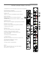
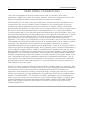
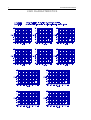
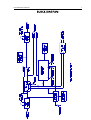
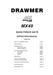
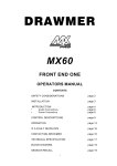
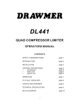
LX20
OPERATORS MANUAL
CONTENTS
SAFETY CONSIDERATIONS
INSTALLATION
INTRODUCTION
FIRST TIME USER
SYSTEM OPERATING LEVELS
FRONT & REAR PANEL LAYOUT
OPERATION
REAR PANEL CONNECTIONS
TECHNICAL SPECIFICATION
LX20 CHARACTERISTICS
BLOCK DIAGRAM
h
DRAWMER ELECTRONICS LTD. 1988
page
page
page
page
page
page
page
page
page
page
page
1
2
2
3
3
4
5
6
7
8
9
COPYRIGHT
This manual is copyrighted © 1988 by Drawmer Electronics, Ltd. With all rights
reserved. Under copyright laws, this manual may not be duplicated in whole or in
part without the written consent of Drawmer.
UPGRADES
In the interests of product development, Drawmer reserve the right to modify or
improve specifications of this product at any time, without prior notice.
1
LX20 OPERATOR’S MANUAL
DRAWMER LX20
Dual Expander/Compressor
SAFETY CONSIDERATIONS
CAUTION - MAINS FUSE
TO REDUCE THE RISK OF FIRE REPLACE THE MAINS FUSE ONLY WITH THE
SAME TYPE, WHICH MUST BE A CLASS 3, 230 VOLT, TIME DELAY TYPE,
RATED AT 32mA WHERE THE MAINS INPUT VOLTAGE SWITCH IS SET TO
230 VOLTS AC. AND 63mA WHERE THE MAINS INPUT VOLTAGE IS 115
VOLTS AC.
ALL FUSES MUST COMPLY WITH IEC127-2.
THE FUSE BODY SIZE IS 20mm x 5mm.
CAUTION - MAINS CABLE
DO NOT ATTEMPT TO CHANGE OR TAMPER WITH THE SUPPLIED MAINS
CABLE.
CAUTION - SERVICING
DO NOT PERFORM ANY SERVICING. REFER ALL SERVICING TO QUALIFIED
SERVICE PERSONNEL.
WARNING
TO REDUCE THE RISK OF FIRE OR ELECTRIC SHOCK DO NOT EXPOSE THIS
EQUIPMENT TO RAIN OR MOISTURE.
2
LX20 OPERATOR’S MANUAL
INSTALLATION
The LX20 is designed for standard 19" rack mounting and occupies 1U of rack space.
Avoid mounting the unit directly above power amplifiers or power supplies that radiate
significant amounts of heat. Fibre or plastic washers may be used to prevent the front
panel becoming marked by the mounting bolts.
INTRODUCTION
Many studios start as a small concern, but quickly expand into serious, productive
environments. Often, this means selling some of the budget equipment, in order to
replace it with equipment of the necessary quality to match the upgraded studio.
Now that you have bought a DRAWMER unit, you have a piece of equipment
which will serve your needs, regardless of the size and quality of the studio.
The compressor is one of the basic tools of a recording studio. Its function is to
reduce or ‘compress’ the dynamic range of a signal so that quiet passages are
audible whilst loud passages do not overload the recording medium, resulting in
excessive amounts of distortion. It performs this function by sensing the level of the
signal and adjusting the gain continuously, so as to give a more constant output.
Essentially, a compressor contains two basic sections: the signal path, which
contains a voltage controlled amplifier/attenuator (VCA) and the ‘side chain’, which
senses the level of the signal and provides the control for the VCA. There are many
ways in which a compressor may be arranged internally, each method producing a
different ‘personality’, thus lending itself to a particular application. A linear
compressor produces the same amount of compression for each increase in signal
level. Threshold, controls the point at which compression occurs, whereas Ratio
adjusts the amount of compression applied to the signal for each increase in level
above the threshold.
An alternative is the ‘soft knee’ characteristic. With this method, the ratio is
increased automatically as the compression increases, which has the advantage of
being easier to use as only one control is required to adjust compression. In some
applications, a ‘soft knee’ characteristic can be more acceptable than linear, but this
would depend on many factors, not least of which is the individual’s opinion.
Because compression effectively increases low level signals, it also increases the
level of background noise, although this is not created by the compressor itself. For
example, compressing vocals will also increase the level of headphone overspill,
breathing etc. This can be overcome by the use of an expander, which is the
opposite of a compressor. Signals below the threshold level are attenuated, so in
the above example, when no vocals are present, the unit will shut off, thus
eliminating the unwanted noise.
THE LX20 EXPANDER/COMPRESSOR
The LX20 is dual channel, ‘soft knee’ compressor with the addition of an expander
and is designed for simplicity of operation. It is suitable for use at system levels of
!10dBu or +4dBu, by changing internal jumper links. Power supply voltages of 115V
or 230V are accommodated via a rear panel switch. The LX20 has a side chain
access point at the rear. This is used to make the compressor section respond in
different ways to various frequencies, which is useful for ‘de-essing’. Another useful
feature of the LX20 is the mute facility. This enables each channel to be shut off
3
LX20 OPERATOR’S MANUAL
completely by either foot switch or another piece of equipment with triggering
facilities, such as the M401 Midi Management System.
FIRST TIME USERS
First time users are well advised to take the time to familiarise themselves with the
principle of compression and the various controls on the LX20. The best way of
doing this is to select various pieces of pre-recorded material and try various
settings, making notes of the results for the future reference.
Piano is a good instrument for experiment. Due to its highly percussive and touch
sensitive nature, adjustments made to the compressor can have a dramatic effect
on the sound. Increase the COMPRESS control to give about 10dB compression for
each piano note struck. Attack and release controls should be set to mid range (12
o’clock) to start with. Short attack times tend to remove the initial attack peak,
whilst long attack times will tend to exaggerate the effect. When using long attack
times, care should be taken to avoid overloading the recording medium. Using a
short release time will enable the compressor to recover quickly, but it tends to
flatten out the sound to an almost constant level, which can sound artificial. A long
release time allows small, fast variations in level to be heard, but fast repeating
notes will not be individually compressed.
In practice, a compromise is made to suit the application. A piano can be made to
sound rather like an organ by using large amounts of compression (20dB or more)
with a fast attack time and a release time of about 0.5 second. In extreme cases like
this, noise can become a problem. This is also the case when recording vocals. The
expander is a useful device for overcoming this problem.
Set the EXPAND control at !30dB. As the piano note dies away, it triggers the
expander, which shuts the sound off. This avoids the increase in noise as the
compressor pushes the gain up during release. If the expander shuts off the sound
to quickly, increase the release time on the compressor. This also affects the
expander. The expander threshold should also be adjusted so that expansion
commences at the correct level.
SYSTEM OPERATING LEVEL
The LX20 is capable of operation at system levels of +4dBu and !10dBu and is
supplied from the factory set to +4dBu. Your dealer will be able to advise you
regarding system level and make any changes that are necessary.
ANY CHANGES MUST BE CARRIED OUT BY THE DEALER.
DO NOT ATTEMPT TO REMOVE THE COVERS FOR ANY REASON.
4
LX20 OPERATOR’S MANUAL
FRONT & REAR PANEL LAYOUT
1) Expand LED. This illuminates at the onset of expansion.
2) Compression indication.
Moves from right to left during compression.
3) Mute LED.
When on, channel is disabled except in Bypass.
4) VU indication.
Measures signal level at output referred to
system level.
i.e. 0dB corresponds to either !10dBu or +4dBu.
5) Bypass switch.
When switched to bypass, signal passes untreated.
6) Stereo Link switch.
Prevents image shifting during stereo operation.
7) Mains power socket.
8) Mains Fuse.
Use only fuses specified on safety page.
9) Mains Voltage changeover switch.
If incorrect voltage is selected refer to an
authorised dealer.
10) Output socket (unbalanced).
11) Mute Socket.
May be connected to foot switch or control unit.
12) Side-Chain send/return socket.
Ring=Send, Tip=Return.
13) Input socket. (unbalanced).
NOTE:
Input, Output & Mute are 3 inch Mono jacks.
Side chain is a stereo jack.
5
LX20 OPERATOR’S MANUAL
OPERATION
EXPAND
This is the threshold control for the expander. Signals below the
threshold level are attenuated, the lower the level, the greater the attenuation. The
attack time is preset at 2mS and the release time is linked to the release time of the
compressor.
The LED above the EXPAND control indicates the onset of expansion. A switch is
provided at the anticlockwise position, which disables the expander when it is not
required.
COMPRESS This serves as the input gain control to the compressor which has a
preset threshold. Simply rotate clockwise until the required amount of compression
is achieved. The amount of compression is indicated by a LED bar indicator on the
front panel. With a signal at system level , setting COMPRESS at #3 will just begin
to compress the signal. 40dB of gain is available which will enable low level signals
from guitar or some non-electrical keyboards to be amplified and compressed in
one operation.
ATTACK
The speed at which the compressor responds to a rise in signal level is
adjusted by the attack control. The sound of any percussive signals can be altered
to some extent by using this control because long attack times allow the initial part
of the signal to escape compression thus giving a certain amount of ‘punch’ to the
sound. Setting this control at the mid-position is a good starting point, further
adjustments being made as required.
RELEASE
When the signal drops in level , the compressor must recover, ready to
accept the next signal peak. The speed at which it does this is governed by the
RELEASE control. The faster the release, the louder the apparent output level, but
most compressors create some distortion when short release times are used, so
care should be taken to arrive at the correct setting. Once again, the mid-position is
a good starting point. The final setting will depend on the nature of the signal in
relation to the final result and individual taste. NB Small amounts of distortion
caused by a short release times can have pleasing effect on some signals (e.g. Bass
guitar) but care should be taken to ensure the distortion does not become excessive
otherwise the results are unpleasant.
OUTPUT
With the LX20, increasing compression also increases the output
level, which is then adjusted by the output control to compensate for the increase.
A simple LED array gives indication of signal levels in volume units (VU). This
enables the output to be adjusted to the required level.
BYPASS
This switch allows comparison between the input signal and the
output. With input at system level the output is adjusted to the same reading on the
VU meter. It should be remembered that if the input is a low level signal,
comparison between input and output serves no useful purpose. This switch is only
of value when input and output are at a similar level.
STEREO LINK
When a stereo signal is being compressed, the stereo link
switch is used to prevent image shifting caused by different signals appearing on
each channel. In this case, the controls of each channel must be set the same.
It is also possible to use the LINK for special effects. For example, if a mono
backing track is fed to one channel which is set to unity gain (Compress control set
to #3) and a vocal track to the other channel with 'Compress' set to, say -6, when
the vocal compresses, the level of the backing track will drop. Subsequent mixing of
the two tracks will result in the backing being attenuated every time a vocal is
present.
6
LX20 OPERATOR’S MANUAL
REAR PANEL CONNECTIONS
The LX20 is equipped with jack sockets at the rear to interface with other
equipment. Apart from input and output sockets, which are unbalanced, the LX20
has two important additional sockets which increase its versatility.
SIDE CHAIN S/R The side chain send and return socket allows an equaliser to be
inserted into the control system of the compressor, thus making the unit more
sensitive to certain frequencies and less sensitive to others. Vocals can benefit
greatly from the addition of side-chain. e.g. In order to add richness to a vocal some
HF and LF. boost may be required prior to compression. In so doing the sibilant
content (esses and t's) can become dominant and tend to spoil the effect. Also, the
bass boost amplifies 'pops' created by bursts of air hitting the microphone. In some
cases this can create a terrific thud. The side chain socket requires a stereo jack
plug where the ring is the signal send, which is connected to the input of an
equaliser. The output of the equaliser is then connected to the tip of the stereo jack.
The equaliser should then be adjusted so as to compensate for any sibilance and/or
‘popping'. Any equaliser can be used for this purpose, parametric or graphic
equalisers being the most versatile for this application. Some trial and error will be
required to achieve the desired results, but in general, boost frequencies between 3
kHz and 8 kHz by about 5dB to 10dB to compensate for sibilance (de-essing) and
boost at 50Hz to 200Hz by the same amount to overcome 'popping'. Having applied
equalisation, the compressor becomes more sensitive to the boosted frequencies,
thereby compressing those frequencies more than the rest of the audio band in this
way, the desired richness is obtained without the unpleasant side effects. This is
just a guide. The final settings will depend on the style of vocal and the individual,
but remember that boosting a frequency in the side chain will cause a reduction in
that frequency at the output
MUTE The mute socket enables the channel to be disabled when not required. This
can be via a foot switch or a control unit of some sort. Shorting the socket disables
the channel, a LED on the front panel indicated when the MUTE facility is in
operation. Now that MIDI is being used extensively, both by the musician and the
studio, the mute port can be operated by any MIDI unit which has a suitable output
socket. The DRAWMER T102 interface and M401 'MIDMAN' are two examples of
units which will control the mute socket on the LX20. When muted, no matter what
signal is present at the input the output will be silent. WHEN THE LX20 IS USED
WITH THE STEREO LINK ON, BOTH MUTE SOCKETS SHOULD BE OPERATED
SIMULTANEOUSLY.
7
LX20 OPERATOR’S MANUAL
TECHNICAL SPECIFICATIONS
SYTEM OPERATING LEVEL
!10dB OR +4dB, selected by internal
switches
INPUT IMPEDANCE
47 Kohms unbalanced
OUTPUT
Unbalanced
NOISE @ unity gain
!85dB (22Hz to 22KHz)
MAX GAIN
40dB
DISTORTION @ unity gain
Less than 0.3%
DISTORTION @ 10dB compression
Less than 0.3%
POWER REQUIREMENTS
115Volt or 230Volt at 50-60Hz, 8 Watts
FUSE RATING
32mA for 230Volt, 63mA for 115Volt
CONFORMING TO IEC127-2
FUSE TYPE
20mm x 5mm, Class 3 Slo-Blo, 250Volt
working
CASE SIZE
482mm (w) x 44mm (h) x 200mm (d)
WEIGHT (incl packaging)
3 Kgs
8
LX20 OPERATOR’S MANUAL
LX20 CHARACTERISTICS
9
LX20 OPERATOR’S MANUAL
BLOCK DIAGRAM