1
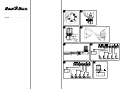
Rain Bird Sales, Inc. Contractor Division RSD-BEx 970 West Sierra Madre Avenue Azusa, CA 91702 USA Phone: (626) 812-3400 Fax: (626) 812-3411 Technical Assistance (USA and Canada only): 800-247-3782 RSD-CEx Rain Bird Sales, Inc. Commercial Division 6640 S. Bonney Avenue Tucson, AZ 85706 USA Phone: (520) 434-6200 Fax: (520) 434-6246 Specification Hotline (USA and Canada only): 800-458-3005 RSD RAIN SENSOR Installation & Operating Instructions RSD RAIN SENSOR Manuel d’Installation et de Fonctionnement RSD REGENSENSOR Rain Bird International, Inc. 145 North Grand Avenue Glendora, CA 91741 USA Phone: (626) 963-9311 Fax: (626) 963-4287 www.rainbird.com Anleitung für Installation und Bedienung EL SENSOR DE LLUVIA RSD Guía de Instalación y Operación SENSOR DE CHUVA RSD Guia da Instalação e da Operação SENSORE PIOGGIA RSD Guida all’Installazione e Utilizzazione RSD REGENVOELER Instructies voor Installatie en Bediening P/N 172182A © 2001 Rain Bird Sprinkler Mfg. Corp. 04/01. All rights reserved. ® Registered trademark of Rain Bird Sprinkler Mfg. Corp. RSD Rain Sensor The RSD Rain Sensor automatically monitors rainfall and shuts off your sprinklers to prevent unnecessary watering. NOTE:The RSD Rain Sensor is a low-voltage device compatible with all 24 volt alternating current (VAC) control circuits and 24 VAC pump start relay circuits. DO NOT USE with any 110/250 VAC devices or circuits, such as direct-acting pump start systems or pump start relays. The RSD Rain Sensor is rated for use with up to three Rain Bird 24VAC, 7VA solenoid valves per station, plus one master valve. 1. Selecting a Location Select a mounting location where the rain-sensing head will receive direct rainfall. Make sure the head extends beyond the roof line, tree limbs, and any other obstructions. Install the Rain Sensor in an area that receives as much rain and sunlight as the grass. Be sure to mount the sensor above spray from sprinklers. Avoid mounting locations such as those shown in Illustration 1. 2. Operation Set Rainfall Setting The rainfall setting determines the amount of rainfall needed to prevent your irrigation system from watering. You can adjust the rainfall setting from 1/8" to 3/4" (5mm to 20mm). The ideal rainfall setting for your location depends on soil type, humidity, amount of direct sunlight the sensor receives, and frequency and amount of rainfall. The table below gives some guidelines to help determine the appropriate rainfall setting. Irrigation site conditions Dry climate / low humidity Infrequent, light rains Rainfall setting 1/8" to 1/4" (5mm to 10 mm) Sensor receives long periods of direct sun Clay-type soils Moist climate / high humidity Frequent, heavy rains 1/2" to 3/4" (15mm to 20mm) Sensor mounted in a mostly shady area Sandy soils NOTE: At the 1/8" or 5mm setting, a very light rainfall will activate the sensor and suspend watering. The 1/8" or 5mm rainfall setting is not recommended in areas with high humidity. To set the rainfall setting, turn the sensor dial cap until the desired rainfall setting lines up with the arrow on the sensor body (A), as shown in Illustration 2. RSD Rain Sensor 1 Set Vent Ring The vent ring determines drying time the length of time the sensor turns off irrigation after a rainfall. For most installations, set the vent ring to the fully open position. For some installations, such as sites where water pools after rainfall, set the vent ring to a partially open position. This will shut down the irrigation system a little longer after a rain. To set the vent ring, turn the vent ring knob below the dial cap to the desired position, as shown in Illustration 3. 3. Mounting NOTE: Follow the installation instructions carefully and install the unit only in full compliance with the National Electrical Code (NEC) or your local electrical code. Bracket Model To install the RSD-BEx Rain Sensor bracket model: 1. Select an appropriate mounting location within 25' (7,6m) of your controller. 2. Drive two mounting screws through the mounting holes (A) in the main mounting bracket, as shown in Illustration 4 (A). Use fasteners appropriate for the mounting surface (wood, tile, masonry, etc.) Conduit Model To install the RSD-CEx Rain Sensor conduit model: 1. Thread the Rain Sensors lead wires through an adaptor fitting appropriate for your installation and screw the sensor into the adaptor, as shown in Illustration 5. 2. Make sure the Rain Sensor head is level and extends far enough beyond the roofline to receive unobstructed rainfall. 3. Run the extension wires through the conduit (if necessary, follow the procedure for wiring a Normally Open controller, as described in Section 4 Rain Sensor Wiring). 4. Secure the adapter fitting to the conduit. Then connect the Rain Sensor to the controller using the appropriate procedure, as described in Section 4. 4. Rain Sensor Wiring All Rain Bird controllers, and most controllers by other manufacturers, are installed using a Normally Closed method. Select the appropriate procedure to install the RSD Rain Sensor to your controller. 2 RSD Rain Sensor Normally Closed Installation NOTE: The short lead wire labeled Normally Open is not used with this installation method. Controllers With Rain Sensor Terminals Many modern controllers (such as Rain Birds E Class, ESP-LX+, and ESP-MC) include built-in terminals for rain sensor lead wires. Dedicated rain sensor terminals are usually labeled sensor or SN on the controllers terminal strip. 1. To connect the rain sensor, remove the jumper wire (if present) from the controllers rain sensor terminals. 2. Connect the lead wires from the rain sensor to the controllers sensor terminals, as shown in Illustration 6. Controllers Without Rain Sensor Terminals Use the procedure below if your controller does NOT have dedicated rain sensor terminals. 1. Disconnect the wire from the common terminal (C or COM) on the controllers terminal strip. Then connect this wire to either of the Rain Sensors leads. 2. Connect the remaining Rain Sensor lead to the common (C or COM) terminal on the controllers terminal strip, as shown in Illustration 7. Normally Open Installation Some non-Rain Bird controllers require rain sensors to be installed Normally Open (N.O.) Use the following procedure if your controller requires normally open installation. 1. Cut either of the Rain Sensors colored lead wires and connect it to the short lead labeled Normally Open. 2. Seal the connection in accordance with the National Electrical Code (NEC) or your local electrical code. 3. Consult your controller manufacturers manual to determine the appropriate procedure for connecting the Rain Sensor to your controller. 5. Testing the System To make sure the RSD Rain Sensor is properly installed, turn on any controller irrigation zone and verify that the zone comes on. Then press the Rain Sensor plunger located in the top of the dial cap, as shown in Illustration 4 (B). The irrigation system should stop watering within a few seconds. If the system does not shut off, check all wiring connections to make sure the rain sensor system is correctly installed. RSD Rain Sensor 3 For assistance, call Rain Bird Technical Services at 800-247-3782 (USA and Canada only). 6. Maintenance The RSD Rain Sensor operates automatically and usually requires no regular maintenance. However, the fibrous disks inside the dial cap sometimes become contaminated with debris or insects. If this happens, use the following procedure to clean the Rain Sensor. 1. Turn the dial cap to the 3/4" rainfall setting, as shown in Illustration 2. 2. Press the tab labeled Press on the side of the sensor body, as shown in Illustration 8 (A). Then turn the dial cap about 1¼ turns further to remove the cap from the sensor body. 3. Remove the plunger and disks from the sensor body, and wash them in clean water. 4. Reinstall the plunger and disks. Then reset the rainfall setting to the desired position, as shown in Illustration 2. Declaration of Conformity Application of Council Directive: 89/336/EEC Standards To Which Conformity Is Declared: EN55022 AS/NZS3548 Class A EN50082-1:1992 EN61000-4-2 EN61000-4-3 ENV50204 EN61000-4-4 EN61000-4-6 EN61000-4-8 Manufacturers Name: Clemar Manufacturing Inc. Manufacturers Address: 7590 Brittania Court San Diego, CA 92713 USA (619) 661-4416 Equipment Description: Irrigation Controller Equipment Class: Generic Res, Comm, LI - Class A Model Name: Rain Sensor I the undersigned, hereby declare that the equipment specified above, conforms to the above Directive(s) and Standard(s). Place: Tijuana, B.C., México Signature: Full Name: John Rafael Zwick Position: General Manager 4 RSD Rain Sensor 1 2 3 4 English ............................................. 1 B A 5 7 6 8