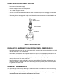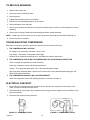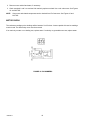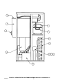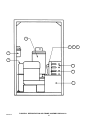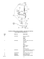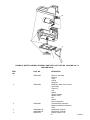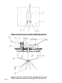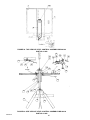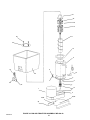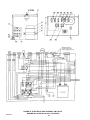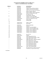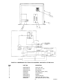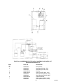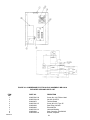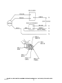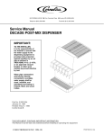
1
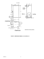
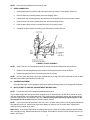
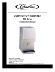
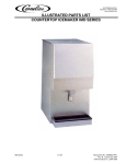
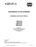
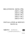
IMI CORNELIUS INC g One Cornelius Place g Anoka, MN 55303-6234 Telephone (800) 238-3600 Installation Manual COUNTERTOP ICEMAKER IMD SERIES Facsimile (612) 422-3246 Distributed By: Commercial Refrigeration Service, Inc. WWW.WorldRestaurantSupply.COM toll free (866) Ice Maker (623) 869-8881 IMPORTANT: TO THE INSTALLER. It is the responsibility of the Installer to ensure that the water supply to the dispensing equipment is provided with protection against backflow by an air gap as defined in ANSI/ASME A112.1.2-1979; or an approved vacuum breaker or other such method as proved effective by test. Water pipe connections and fixtures directly connected to a potable water supply shall be sized, installed, and maintained according to Federal, State, and Local Codes. Part No. 638085277 Revisied October 16, 2000 Revision B THIS DOCUMENT CONTAINS IMPORTANT INFORMATION This Manual must be read and understood before installing or operating this equipment IMI CORNELIUS INC; 94-2000 PRINTED IN U.S.A TABLE OF CONTENTS Page SAFETY INFORMATION . . . . . . . . . . . . . . . . . . . . . . . . . . . . . . . . . . . . . . . . . . . . . . . . . . . . 1 RECOGNIZE SAFETY INFORMATION . . . . . . . . . . . . . . . . . . . . . . . . . . . . . . . 1 UNDERSTAND SIGNAL WORDS . . . . . . . . . . . . . . . . . . . . . . . . . . . . . . . . . . . . 1 FOLLOW SAFETY INSTRUCTIONS . . . . . . . . . . . . . . . . . . . . . . . . . . . . . . . . . 1 CO2 (CARBON DIOXIDE) WARNING . . . . . . . . . . . . . . . . . . . . . . . . . . . . . . . . 1 SHIPPING, STORING, OR RELOCATING UNIT . . . . . . . . . . . . . . . . . . . . . . . 1 SPECIFICATION CHART . . . . . . . . . . . . . . . . . . . . . . . . . . . . . . . . . . . . . . . . . . . . . . . . . . . 3 INSTALLATION INSTRUCTIONS . . . . . . . . . . . . . . . . . . . . . . . . . . . . . . . . . . . . . . . . . . . . 6 GUIDE TO SERVICE . . . . . . . . . . . . . . . . . . . . . . . . . . . . . . . . . . . . . . . . . . . . . . . . . . . . . . . 9 ICEMAKER CLEANING AND SANITIZING PROCEDURES . . . . . . . . . . . . . . . . . 9 MAINTENANCE . . . . . . . . . . . . . . . . . . . . . . . . . . . . . . . . . . . . . . . . . . . . . . . . . . . . . . . 9 MONTHLY . . . . . . . . . . . . . . . . . . . . . . . . . . . . . . . . . . . . . . . . . . . . . . . . . . . . . . . . . . . . 9 QUARTERLY . . . . . . . . . . . . . . . . . . . . . . . . . . . . . . . . . . . . . . . . . . . . . . . . . . . . . . . . . . 9 SEMI–ANNUALLY . . . . . . . . . . . . . . . . . . . . . . . . . . . . . . . . . . . . . . . . . . . . . . . . . . . . . 9 WATER LEVEL CONTROL . . . . . . . . . . . . . . . . . . . . . . . . . . . . . . . . . . . . . . . . . . . . . . . . . 11 HOW WATER LEVEL CONTROL WORKS . . . . . . . . . . . . . . . . . . . . . . . . . . . . . . . . 11 PURPOSE OF WATER LEVEL CONTROL . . . . . . . . . . . . . . . . . . . . . . . . . . . . . . . . 11 TO REPLACE WATER LEVEL CONTROL . . . . . . . . . . . . . . . . . . . . . . . . . . . . . . . . 11 TO REPLACE WATER LEVEL SAFETY SWITCH . . . . . . . . . . . . . . . . . . . . . . . . . . 11 ICE LEVEL CONTROL . . . . . . . . . . . . . . . . . . . . . . . . . . . . . . . . . . . . . . . . . . . . . . . . . 11 TEMPERATURE / PRESSURE CHARTS* . . . . . . . . . . . . . . . . . . . . . . . . . . . . 12 AIR TEMPERATURE . . . . . . . . . . . . . . . . . . . . . . . . . . . . . . . . . . . . . . . . . . . . . . . 12 10 LBS. DISCHARGE PRESSURE . . . . . . . . . . . . . . . . . . . . . . . . . . . . . . . . . . 12 WATER TEMPERATURE . . . . . . . . . . . . . . . . . . . . . . . . . . . . . . . . . . . . . . . . . . . 12 IMD300–5 & IMD300–15 . . . . . . . . . . . . . . . . . . . . . . . . . . . . . . . . . . . . . . . . . . . . 12 IMD300–30 . . . . . . . . . . . . . . . . . . . . . . . . . . . . . . . . . . . . . . . . . . . . . . . . . . . . . . . 12 IMD600–30, IMD600–90 . . . . . . . . . . . . . . . . . . . . . . . . . . . . . . . . . . . . . . . . . . . . 12 REFRIGERATION SYSTEM ADJUSTMENTS . . . . . . . . . . . . . . . . . . . . . . . . . . . . . 12 EXPANSION VALVE . . . . . . . . . . . . . . . . . . . . . . . . . . . . . . . . . . . . . . . . . . . . . . . . . . . 12 ADJUSTMENT AND TROUBLESHOOTING . . . . . . . . . . . . . . . . . . . . . . . . . . . . . . . 12 CONDENSER MODULATING VALVE . . . . . . . . . . . . . . . . . . . . . . . . . . . . . . . . . . . . . 13 CONDENSER MODULATING VALVE REMOVAL . . . . . . . . . . . . . . . . . . . . . . . . . . 13 GEAR MOTOR . . . . . . . . . . . . . . . . . . . . . . . . . . . . . . . . . . . . . . . . . . . . . . . . . . . . . . . . 14 SHAFT SEAL INSTALLATION AND REPLACEMENT (SEE FIGURE 7.) . . . . . 14 AUGER & EXTRUDING HEAD REMOVAL . . . . . . . . . . . . . . . . . . . . . . . . . . . . . . . . 15 INSTALLATION AND SHAFT SEAL REPLACEMENT (SEE FIGURE 9.) . . . . . . 15 UPPER NUT AND BEARINGS . . . . . . . . . . . . . . . . . . . . . . . . . . . . . . . . . . . . . . . . . . . 15 TO REPLACE BEARINGS . . . . . . . . . . . . . . . . . . . . . . . . . . . . . . . . . . . . . . . . . . . . . . 16 TROUBLESHOOTING COMPRESSOR . . . . . . . . . . . . . . . . . . . . . . . . . . . . . . . . . . . 16 ELECTRICAL CHECKOUT . . . . . . . . . . . . . . . . . . . . . . . . . . . . . . . . . . . . . . . . . . . . . . 16 OVERLOAD CHECK – FIGURE 10. . . . . . . . . . . . . . . . . . . . . . . . . . . . . . . . . . . . . . . 17 COMPRESSOR CHECK – FIGURE 11. . . . . . . . . . . . . . . . . . . . . . . . . . . . . . . . . . . . 17 CAPACITOR CHECK . . . . . . . . . . . . . . . . . . . . . . . . . . . . . . . . . . . . . . . . . . . . . . . . . . . 17 i 638085277 TABLE OF CONTENTS (cont’d) Page TROUBLESHOOTING GEAR MOTORS . . . . . . . . . . . . . . . . . . . . . . . . . . . . . . . . . . 17 THE GEARMOTOR WILL NOT RUN . . . . . . . . . . . . . . . . . . . . . . . . . . . . . . . . . 17 THE GEARMOTOR STARTS BUTS TRIPS REPEATEDLY ON THE OVERLOAD PROTECTOR: . . . . . . . . . . . . . . . . . . . . . . . . . . . . . . . . . . . . . . . . . 17 THE MOTOR RUNS BUT OUTPUT SHAFT DOES NOT ROTATE: . . . . . . . 17 OVERLOAD CHECK: . . . . . . . . . . . . . . . . . . . . . . . . . . . . . . . . . . . . . . . . . . . . . . 17 MOTOR CHECK: . . . . . . . . . . . . . . . . . . . . . . . . . . . . . . . . . . . . . . . . . . . . . . . . . . 18 SAFETY CONTROLS . . . . . . . . . . . . . . . . . . . . . . . . . . . . . . . . . . . . . . . . . . . . . . . . . . . . . . 19 GUIDE TO GOOD ICE . . . . . . . . . . . . . . . . . . . . . . . . . . . . . . . . . . . . . . . . . . . . . . . . . . . . . . 20 TROUBLESHOOTING CHART – ICEMAKER NOT OPERATING . . . . . . . . . . . . . . . . 21 PARTS LIST . . . . . . . . . . . . . . . . . . . . . . . . . . . . . . . . . . . . . . . . . . . . . . . . . . . . . . . . . . . . . . 28 REFRIGERATION AND FRAME ASSEMBLY IMD 300-15 PARTS LIST . . . . . . . 29 REFRIGERATION AND FRAME ASSEMBLY IMD 300–30 AND IMD 600–30 PARTS LIST . . . . . . . . . . . . . . . . . . . . . . . . . . . . . . . . . . . . . . . . . . . . . . . . . . . . . . . . . . 31 REFRIGERATION AND FRAME ASSEMBLY IMD 600–90 PART LIST . . . . . . . . 33 ICE LEVEL CONTROL ASSEMBLY PARTS LIST FOR PART NO 32770 IMD 300–15 AND 32770–002 IMD302–15 . . . . . . . . . . . . . . . . . . . . . . . . . . . 37 ICE LEVEL CONTROL ASSEMBLY PARTS LIST IMD300–30 AND IMD600–30 PART NUO 31494–001 (115V) PART NO. 31494–002 (208V/220V) . . . . . . . . . . . 39 ICE LEVEL CONATROL ASSEMBLY PARTS LIST IMD 600–90 PART NO. 31892 . . . . . . . . . . . . . . . . . . . . . . . . . . . . . . . . . . . . . . . . . . . . . . . . . . . . . . 41 BIN AND FRONT END ASSEMBLY PARTS LIST IMD 300-15, IMD 300-30 AND 600-30 . . . . . . . . . . . . . . . . . . . . . . . . . . . . . . . . . . . . . . . . . . . . . . . . . . . . . . . . . . . 43 BIN AND FRONT END ASSEMBLY IMD PARTS LIST 600-90 . . . . . . . . . . . . . . . 45 ELECTRICAL BOX ASSEMBLY PARTS LIST, PART NO. 32776 IMD 300–15 AND PART NO. 32776-002 IMD 302-15 . . . . . . . . . . . . . . . . . . . . . . . . . . . . . . . . . . . 47 ELECTRICAL BOX ASSEMBLY PARTS LIST IMD 300–30, IMD 600–30 AND IMD 600-90 (ALL VOLTAGES) . . . . . . . . . . . . . . . . . . . . . . . . . . 49 DISPENSE MECHANISM ASSEMBLY PARTS LIST IMD 300-15, IMD300-30, IMD 600-30 AND IMD 600-90 PARTS LIST . . . . . . . . . . . . . . . . . . . . . . . . . . . . . . . . 56 GEAR MOTOR ASSEMBLY PARTS LIST . . . . . . . . . . . . . . . . . . . . . . . . . . . . . . . . . 59 WARRANTY . . . . . . . . . . . . . . . . . . . . . . . . . . . . . . . . . . . . . . . . . . . . . . . . . . . . . . . . . . . . . . 60 LIST OF FIGURES FIGURE 1. DIMENSION DRAWING (15 LB.) IMD 300–15 . . . . . . . . . . . . . . . . . . . 4 FIGURE 2. DIMENSION DRAWINGS (30 LBS.) IMD300–30 AND IMD600–30 . 5 FIGURE 3. DIMENSION DRAWINGS (90 LBS.) IMD600–90 . . . . . . . . . . . . . . . . . 5 FIGURE 4. FLOAT ASSEMBLY . . . . . . . . . . . . . . . . . . . . . . . . . . . . . . . . . . . . . . . . . . 7 FIGURE 5. UPPER BEARING AND AUGER ASSEMBLY . . . . . . . . . . . . . . . . . . . 10 FIGURE 6. ADJUSTMENT SCREW . . . . . . . . . . . . . . . . . . . . . . . . . . . . . . . . . . . . . . 13 FIGURE 7. IMD 300 SHAFT SEAL . . . . . . . . . . . . . . . . . . . . . . . . . . . . . . . . . . . . . . 14 FIGURE 8. AUGER AND EXTRUDING HEAD REMOVAL . . . . . . . . . . . . . . . . . . 14 FIGURE 9. IMD 600 SHAFT SEAL . . . . . . . . . . . . . . . . . . . . . . . . . . . . . . . . . . . . . . . 15 FIGURE 10. OVERLOAD CHECK . . . . . . . . . . . . . . . . . . . . . . . . . . . . . . . . . . . . . . . 16 FIGURE 11. COMPRESSOR CHECK . . . . . . . . . . . . . . . . . . . . . . . . . . . . . . . . . . . . 16 638085277 ii TABLE OF CONTENTS (cont’d) Page FIGURE 12. PIN NUMBERS . . . . . . . . . . . . . . . . . . . . . . . . . . . . . . . . . . . . . . . . . . . . 18 FIGURE 13. GEAR MOTOR OVERLOAD . . . . . . . . . . . . . . . . . . . . . . . . . . . . . . . . . 19 FIGURE 14. SCHEMATIC IMD 300–15 . . . . . . . . . . . . . . . . . . . . . . . . . . . . . . . . . . . 22 FIGURE 15. SCHEMATIC IMD 300–30, IMD600–30, IMD601–30, IMD600–90, AND IMD601–90 . . . . . . . . . . . . . . . . . . . . . . . . . . . . . . . . . . . . . . . . . . . . . . . . . . . . . . . 23 FIGURE 16. SCHEMATIC IMD302–30, IMD602–30, AND IMD602–90 . . . . . . . . 24 FIGURE 17. IMD 300–15 CABINET PARTS ASSEMBLY AND PARTS LIST . . . 25 FIGURE 18. IMD300–30 AND IMD600–30 CABINET PARTS ASSEMBLY AND PARTS LIST . . . . . . . . . . . . . . . . . . . . . . . . . . . . . . . . . . . . . . . . . . . . . . . . . . . . . . 26 FIGURE 19. IMD600–90 CABINET PARTS ASSEMBLY AND PARTS LIST . . . . 27 FIGURE 20. REFRIGERATION AND FRAME ASSEMBLY IMD 300–15 . . . . . . . 28 FIGURE 21. REFRIGERATION AND FRAME ASSEMBLY IMD 300–30 AND IMD 600–30 . . . . . . . . . . . . . . . . . . . . . . . . . . . . . . . . . . . . . . . . . . . . . . . . . . . . . . 30 FIGURE 22. REFRIGERATION AND FRAME ASSEMBLY IMD 600–90 . . . . . . . 32 FIGURE 23. WATER CONTROL ASSEMBLY AND PARTS LIST PART NO. 04643-04 IMD 300-30 AND IMD 600-30 . . . . . . . . . . . . . . . . . . . . . . . . . . . . . . . . . . . 34 FIGURE 24. WATER CONTROL ASSEMBLY AND PARTS LIST PART NO. 32843 IMD 300–15 32545 IMD 600-90 . . . . . . . . . . . . . . . . . . . . . . . . . . 35 FIGURE 25. TOP VIEW ICE LEVEL CONTROL ASSEMBLY PART NO. 32770 IMD 300-15 AND 32770-002 IMD 302–5 . . . . . . . . . . . . . . . . . . 36 FIGURE 26. SIDE VIEW ICE LEVEL CONTROL ASSEMBLY PART NO. 32770 IMD 300-15 AND 32770-002 IMD 302–5 . . . . . . . . . . . . . . . . . . 36 FIGURE 27. TOP VIEW ICE LEVEL CONTROL ASSEMBLY IMD 300-30 AND IMD 600-30PART NO. 31494-001 (115V) PART NO. 31494-002 (208V/220V) . . 38 FIGURE 28. SIDE VIEW ICE LEVEL CONTROL ASSEMBLY IMD 300-30 AND IMD 600-30PART NO. 31494-001 (115V) PART NO. 31494-002 (208V/220V) . . 38 FIGURE 29. TOP VIEW ICE LEVEL CONTROL ASSEMBLY IMD 600-90 PART NO. 31892 . . . . . . . . . . . . . . . . . . . . . . . . . . . . . . . . . . . . . . . . . . . . . . . . . . . . . . 40 FIGURE 30. SIDE VIEW ICE LEVEL CONTROL ASSEMBLY IMD 600-90 PART NO. 31892 . . . . . . . . . . . . . . . . . . . . . . . . . . . . . . . . . . . . . . . . . . . . . . . . . . . . . . 40 FIGURE 31. BIN AND FRONT END ASSEMBLY IMD 300-15, IMD 300-30 AND 600-30 . . . . . . . . . . . . . . . . . . . . . . . . . . . . . . . . . . . . . . . . . . . . . . . . . . . . . . . . . . . 42 FIGURE 32. BIN AND FRONT END ASSEMBLY IMD 600-90 . . . . . . . . . . . . . . . . 44 FIGURE 33. ELECTRICAL BOX ASSEMBLY PART NO. 32776 IMD 300–15 AND PART NO. 32776-002 IMD 302-15 . . . . . . . . . . . . . . . . . . . . . . . . . . . . . . . . . . . 46 FIGURE 34. ELECTRICAL BOX ASSEMBLY IMD 300–30 AND IMD 600–30 IMD 600-90 (ALL VOLTAGES) . . . . . . . . . . . . . . . . . . . . . . . . . . 48 FIGURE 35. COMPRESSOR ELECTRICAL BOX ASSEMBLY AND PARTS LIST IMD 300-30, 600-30 AND 601-30 . . . . . . . . . . . . . . . . . . . . . . . . . . . . . . . . . . . . . . . . . 50 FIGURE 36. COMPRESSOR ELECTRICAL BOX ASSEMBLY AND PARTS LIST IMD 302-30 . . . . . . . . . . . . . . . . . . . . . . . . . . . . . . . . . . . . . . . . . . . . . . . . . . . . . . . . . . . 51 FIGURE 37. COMPRESSOR ELECTRICAL BOX ASSEMBLY AND PARTS LIST IMD 602-30 . . . . . . . . . . . . . . . . . . . . . . . . . . . . . . . . . . . . . . . . . . . . . . . . . . . . . . . . . . . 52 FIGURE 38. COMPRESSOR ELECTRICAL BOX ASSEMBLY AND PARTS LIST IMD 600-90 AND IMD 601–90 . . . . . . . . . . . . . . . . . . . . . . . . . . . . . . . . . . . . . . . . . . . 53 FIGURE 39. COMPRESSOR ELECTRICAL BOX ASSEMBLY IMD 602-90 EXPLODED VIEW AND PARTS LIST . . . . . . . . . . . . . . . . . . . . . . . . . . . . . . . . . . . . . 54 FIGURE 40. DISPENSE MECHANISM ASSEMBLY IMD 300-15, IMD300-30, IMD 600-30 AND IMD 600-90 EXPLODED VIEW . . . . . . . . . . . . . . . . . . . . . . . . . . . . . . . . . . . . . . . . . . . . . . . . . . . . . iii 55 638085277 TABLE OF CONTENTS (cont’d) Page FIGURE 41. GEAR MOTOR ASSEMBLY . . . . . . . . . . . . . . . . . . . . . . . . . . . . . . . . . 57 FIGURE 42. GEAR MOTOR ASSEMBLY WIRING DIAGRAM (ALL VOLTAGES) EXPLODED VIEW . . . . . . . . . . . . . . . . . . . . . . . . . . . . . . . . . . . . . . . . . . . . . . . . . . . . . 58 LIST OF TABLES SPECIFICATION CHART . . . . . . . . . . . . . . . . . . . . . . . . . . . . . . . . . . . . . . . . . . . . . . . 3 TEMPERATURE/PRESSURE CHARTS . . . . . . . . . . . . . . . . . . . . . . . . . . . . . . . . . . . 12 638085277 iv SAFETY INFORMATION Recognize Safety Information This is the safety-alert symbol. When you see this symbol on our machine or in this manual, be alert to the potentially of personal injury. Follow recommended precautions and safe operating practices. Understand Signal Words DANGER A signal word - DANGER, WARNING, OR CAUTION is used with the safety-alert symbol. DANGER identifies the most serious hazards. WARNING Safety signs with signal word DANGER or WARNING are typically near specific hazards. General precautions are listed on CAUTION safety signs. CAUTION also calls attention to safety messages in this manual. CAUTION Follow Safety Instructions Carefully read all safety messages in this manual and on your machine safety signs. Keep safety signs in good condition. Replace missing or damaged safety signs. Learn how to operate the machine and how to use the controls properly. Do not let anyone operate the machine without instructions. Keep your machine in proper working condition. Unauthorized modifications to the machine may impair function and/or safety and affect the machine life. CO2 (Carbon Dioxide) Warning CO2 Displaces Oxygen. Strict Attention must be observed in the prevention of CO2 (carbon dioxide) gas leaks in the entire CO2 and soft drink system. If a CO2 gas leak is suspected, particularly in a small area, immediately ventilate the contaminated area before attempting to repair the leak. Personnel exposed to high concentration of CO2 gas will experience tremors which are followed rapidly by loss of consciousness and suffocation. Shipping, Storing, Or Relocating Unit CAUTION: Before shipping, storing, or relocating this Unit, the syrup systems must be sanitized and all sanitizing solution must be purged from the syrup systems. All water must also be purged from the plain and carbonated water systems. A freezing ambient temperature will cause residual water remaining inside the Unit to freeze resulting in damage to internal components of the Unit. CAUTION: Very high discharge pressure is present in system. Quick disconnects on your gauges will minimize Danger and loss of refrigerant. 1 638085277 CAUTION: Unit requires a separate electrical line. See Manual for proper fuse size. WARNING: There Must Be Adequate Clearance Around Ice Maker. Allow Minimum 6” Air Intake and 4” For Air Exhaust on all sides and open to the front. NOTICE Unit must be installed per local plumbing and electrical codes. See Installation Manual for unit requirements. Failure to do so may cause damage to unit, which would void the warranty. NOTICE Using Any Parts Other Than Genuine Factory Manufactured Parts Relieves the Manufacturer of all Liability. NOTICE Manufacturer Reserves The Right To Change Specifications At Any Time. 638085277 2 SPECIFICATION CHART Models Condensing Unit VAC Hz Ph Comp RLA Fan Amps Grmtr Amps Refrigerant Oz. Type Circuit Fuse IMD300–15A Air Cooled 115 60 1 6 0.82 2 12 R134a 15 IMD302–15A Air Cooled 220/240 50 1 3 0.5 1.6 12 R134a 15 IMD300–30A Air Cooled 115 60 1 10.1 1 2 28 R404A 20 IMD300–30W Water Cooled 115 60 1 10.1 N/A 2 13 R404A 20 IMD301–30A Air Cooled 208/230 60 1 5.7 1 1.6 28 R404A 20 IMD301–30W Water Cooled 208/230 60 1 5.7 N/A 1.6 13 R404A 20 IMD302–30A Air Cooled 220/240 50 1 5.3 0.5 1.6 28 R404A 20 IMD302–30W Water Cooled 220/240 50 1 5.3 N/A 1.6 13 R404A 20 IMD600–30A Air Cooled 115 60 1 12 1 2 28 R404A 20 IMD600–30W Water Cooled 115 60 1 12 N/A 2 14 R404A 20 IMD601–30A Air Cooled 208/230 60 1 7.7 1 1.6 28 R404A 20 IMD601–30W Water Cooled 208/230 60 1 7.7 N/A 1.6 14 R404A 20 IMD602–30W Water Cooled 220/240 50 1 8.2 N/A 1.6 14 R404A 20 IMD600–90A Air Cooled 115 60 1 12 1 2 24 R404A 20 IMD600–90W Water Cooled 115 60 1 12 N/A 2 14 R404A 20 IMD601–90A Air Cooled 208/230 60 1 7.7 1 1.6 24 R404A 20 IMD601–90W Water Cooled 208/230 60 1 7.7 N/A 1.6 14 R404A 20 IMD602–90A Air Cooled 220/240 50 1 8.2 0.5 1.6 24 R404A 20 IMD602–90W Water Cooled 220/240 50 1 8.2 N/A 1.6 14 R404A 20 NOTE: FOR UNITS NOT LISTED IN ABOVE CHART, REFER TO NAMEPLATE OR CONTACT FACTORY SERVICE. 3 638085277 SHIPPING WT. 189 LBS. (APPROX.) FIGURE 1. DIMENSION DRAWING (15 LB.) IMD 300–15 638085277 4 SHIPPING WT. (IMD300–30) 220 LBS. (APPROX.) SHIPPING WT. (IMD600–30) 240 LBS. (APPROX.) FIGURE 2. DIMENSION DRAWINGS (30 LBS.) IMD300–30 AND IMD600–30 SHIPPING WT. 225 LBS. (APPROX.) FIGURE 3. DIMENSION DRAWINGS (90 LBS.) IMD600–90 5 638085277 INSTALLATION INSTRUCTIONS A.. REMOVE ICEMAKER FROM CARTON: 1. Keep unit in the upright position, remove carton and pallet from unit and inspect unit for damage. Upon inspection of unit, if any damage is found, file a claim with carrier immediately. 2. Locate Startup Card either on outside of container or on plastic liner. Fill in proper information and send one copy to factory, and other copy to Distributor. Postage is prepaid. B.. CABINET REMOVAL 1. Locate and remove the (2) screws from under the front cover. Lift cover forward and up to remove. 2. Lift up front edge of top cover. Slide back about 1/2 inch and remove. 3. Remove (6) screws from the front of the machine. 4. Remove side panels by sliding the front edge out and then back slightly to disengage. 5. Remove the front splash panel by lifting slightly to disengage the front, then tilt forward and remove. 6. Remove bin top and remove shipping insert. C.. PREPARATION OF INSTALLATION SITE 1. The refrigeration system on air cooled units requires airflow, so a well ventilated area should be chosen. A minimum of (6) inches must be maintained, free of any obstruction, for air intake. A minimum of (4) inches clearance is required for air exhaust. 2. With template provided make the necessary provisions in the counter for water, drain and the electrical hook–up. Provisions are available for rear and bottom connections of water and electrical. Use hole plugs provided to plug unused holes. D.. WATER INLET HOOK–UP: 1. Water Inlet – Fitting is a 1/4” SAE male flare located at the rear of the unit. Connect water supply with a 1/4”or larger copper or flexible tubing. 2. Water Pressure – Unless otherwise specified, the unit is designed to operate on water pressures between 10 P.S.I. and 90 P.S.I. (NOTE: for pressures above 90 P.S.I. a regulator must be installed). 3. Water Cooled Condensers 4. a.. Inlet to modulating valve uses 3/8” FPT. Use b.. Outlet is 3/8” FPT. separate 3/8” or larger water line. Filter Conditioners are recommended on supply lines to icemakers. Never run the water supply to water cooled Condenser through Filter/Conditioner, it uses up the cartridge unnecessarily and a saturated cartridge can starve the icemaker causing premature component damage. Separate water supplies are recommended. NOTE: Unit must be installed per local plumbing code. E.. ELECTRICAL SUPPLY 1. 2. Power Access – Is provided by way of a 7/8” dia. hole in both the base and the rear panel. Route incoming power in conduit, to icemaker electrical control box. Make connections to wires provided in control box and ground lug/screw. Plug unused hole. Fused Line – Should be a dedicated circuit checked and sized according to electrical rating shown on unit nameplate. 6 638085277 NOTE: Unit must be installed per local electrical code. F.. DRAIN CONNECTION 1. Install splash panel on machine and hold in place with (2) screws. Do not tighten at this time. 2. Remove drain tray mounting bracket from their shipping carton. 3. Clip the drain tray mounting bracket onto the bottom of the splash panel in the brackets provided. 4. Hook the drain tray into the splash panel and onto the mounting bracket. 5. Push the drain elbow securely onto the drain tray. Do not glue in place. 6. Complete the drain hookup according to the instructions provided with unit FIGURE 4. FLOAT ASSEMBLY NOTE: Steps 7 and 8 to be completed only after all start up checks and adjustments are performed. 7. Replace side panels tightening all (6) screws (including splash panel screws left loose). 8. Replace top panel and front cover and secure with (2) screws. NOTE: In those cases where the unit is base mounted and not on legs it should be sealed all around the base with NSF listed sealant. (IMI Wilshire P/N 04815–B). G.. AUGER ENGAGEMENT Be certain that auger is fully engaged to lower drive and that extruding head is fully engaged to evaporator. H.. INITIAL START UP, CHECKS & ADJUSTMENT INSTRUCTIONS NOTE: Do not start unit before completing Installation steps A–G. Turn on water supply and main power switch (located on top of electrical box). All IMD 30 lb. and 90 lb. series units are equipped with a 45 second delay timer. This means that the refrigeration system will not start until 45 seconds of dispense are accumulated in the timer. Start the refrigeration system by depressing the ice dispense button for 45 seconds. Make the following system checks: NOTE: If unit will not start be sure water reservoir is full. Low water safety control must be properly adjusted to start and shut down unit. If water level drops below bottom of reservoir, unit must shut down. Adjustment is made by moving magnet up or down. Water Level – If necessary adjust Float by bending float arm up or down as needed, push float assembly down until unit stops running. Release float and unit will restart. Keep water in reservoir at level line while unit is in operation. See Figure 1. 7 638085277 Low Water Safety Control – Adjust magnet by bending magnet arm as shown in figure 1 to shut down unit if the water level drops below the line on the side of the reservoir. Bin Control – Remove four screws from top of bin cover and lift cover so bin control plate can be manually lifted until unit shuts down. Release plate and unit will restart (On IMD300–30, IMD600–30 and IMD600–90 the dispense button must be depressed for 45 seconds before unit will start). Replace screws. Dispense Switch and Mechanism – By depressing the dispense switch, the dispense mechanism door on the storage bin will open, and chain, sprockets, and agitator will rotate counterclockwise. NOTE: 638085277 If any of these checks or adjustments cannot be achieved, refer to Troubleshooting Section of this manual or call our technical support center for assistance at 1–800–238–3600. 8 GUIDE TO SERVICE ICEMAKER CLEANING AND SANITIZING PROCEDURES Do not use any of the ice made during cleaning operations. Clean and sanitize ice storage area when cleaning icemaker. 1. Turn machine off. 2. Shut off water supply. 3. Remove ice from storage bin. 4. Mix approved cleaner (2 gallons as directed). Recommended cleaner: Calgon Corp. of Virginia Chemicals, ice machine cleaner. Mixture: 3-1/3 ounces per gallon of water. Do not use nickel safe cleaners. 5. Turn machine on and add cleaner solution to water level control (float reservoir) until 2 gallons have been used. 6. Turn on water supply and run machine for 15 minutes. 7. Turn off machine and remove and discard all ice. 8. Sanitize using household liquid bleach (50 ppm chlorine). Mixture: 1 fluid ounce per gallon room temperature water. 2 minute exposure time. 9. Sanitize pre–cleaned inside areas of storage bin liner, door frame, door, as well as exposed surfaces of the evaporator assembly and bin shutoff assembly with sanitizing solution and allow to air dry. MAINTENANCE Preventive maintenance can increase the trouble free life of your icemaker. Many authorized service agencies offer service contracts for your icemaker. Contact your local distributor for further information. MONTHLY 1. Clean the condenser. Use a brush, vacuum cleaner or blow from inside with air or CO2 gas. If unit is provided with and air filter, clean or replace. 2. Inspect water feed reservoir at lease once a month until a definite pattern for cleaning and sanitizing has been established. QUARTERLY This is the maximum period of time between cleaning and sanitizing the icemaker. In addition to recommended monthly procedure, and if a more frequent cleaning and sanitizing pattern has not been established, unit must be cleaned and sanitized. SEMI–ANNUALLY Semi-Annually in addition to all previously established service procedures perform the following: 1. Check for water leaks in tube connections, water fittings and lower icemaker water seal. 2. Check drain tubes for clogs and “aged” tubes. Replace if tubes are stained or brittle. 3. Check for signs of condensation. Clean where necessary and replace insulation properly. 9 638085277 4. Check safety circuits for proper operation. 5. Check refrigeration system (see page12 12). 6. Check unit for abnormal noise. Tighten machine and cabinet screws, if necessary. 7. Check white upper bearings on auger assembly. If bearings are less than 1/16Ȃ thick, replace. See Figure 5 REPLACE 1/16Ȃ OK 1/16Ȃ OK REPLACE FIGURE 5. UPPER BEARING AND AUGER ASSEMBLY NOTE: 638085277 preventive maintenance can increase the trouble–free life of your ice maker. Failure to perform preventive maintenance could void your equipment warranty 10 WATER LEVEL CONTROL HOW WATER LEVEL CONTROL WORKS When water is introduced through the inlet fitting the float rises. the float pushes against a lever which in turn forces the poppet assembly against the inlet fitting valve seat which seals the water off, (See Figure 4). Before the water inlet is sealed the safety switch is operated. In the event of a water failure the float would drop down and operate the safety switch to shut off the machine. If water level control will not shut off and seal at level as indicated, be sure inlet pressure does not exceed recommended factory operating range. Under ordinary circumstances adjustment should not be necessary providing it was properly adjusted when unit was installed or relocated. If, however, the control becomes inoperative, repair or replace. See Start-Up Adjustment, page 7 . PURPOSE OF WATER LEVEL CONTROL 1. To automatically maintain proper water level in the evaporator when unit is running and making ice. 2. A safety switch is operated in the event of an interruption in water supply. The switch shuts off the electrical power to the icemaker and its refrigeration system. Switch will reset as soon as cause of water failure has been corrected and proper water level in icemaker has again been reached. 3. The transparent bowl not only provides a visible check of water level, but also is a good guide to the internal conditions which exist within the icemaker assembly itself. (See Cleaning Procedure.) TO REPLACE WATER LEVEL CONTROL 1. Shut off the water supply. Shut off the main power switch or unplug the ice dispenser from electrical outlet. 2. Remove the flexible tubing from bottom of water level control and drain water from water level control and evaporator. 3. Remove flexible tubing at bottom of water level bowl connected to the overflow. 4. Hold water inlet fitting with proper tool to prevent it from rotating when disconnecting the water inlet. 5. Remove wing nut holding water control to its mounting bracket. Control can be removed by lifting straight up. TO REPLACE WATER LEVEL SAFETY SWITCH 1. Shut off main power switch or unplug the ice dispenser from electrical outlet. 2. Unplug molex connector connecting switch to electrical box. 3. Remove the 2 screws anchoring the water level safety switch to the bottom of the water level control mounting bracket. ICE LEVEL CONTROL The ice level control assembly is secured to the top of the ice storage container cover. The cover is secured to the storage container with four screws. The level control switch is operated by a plate assembly located beneath the diaphragm. When the plate assembly is down due to lack of ice in storage container, electrical impulse is sent to compressor, starting the ice making cycle. As ice level increases in storage container, the plate assembly is pushed up. When storage container is full, it de–actuates the switch, stopping the compressor and ice making cycle. 11 638085277 The operating positions of the switch are fixed, no adjustments are necessary. If switch replacement becomes necessary, simply disconnect cable at connector, remove wires from switch. TEMPERATURE / PRESSURE CHARTS* $ 10 lbs. Discharge Pressure Water Temperature IMD600–30, IMD600–90 IMD300–5 & IMD300–15 IMD300–30 65_ 90_ 50_ 80 85 90 60_ 92 97 102 70_ 114 120 124 80_ 124 120 147 90_ 161 167 171 100_ 187 193 195 Air Temperature 40_ 40_ 65_ 90_ 40_ 65_ 90_ 162 166 168 174 177 180 188 192 194 202 205 208 214 218 220 230 233 236 245 249 251 265 269 272 275 279 281 300 304 307 309 313 315 328 334 340 NOTE: The thermostatic expansion valve is non–adjustable on all models. REFRIGERATION SYSTEM ADJUSTMENTS A complete understanding of the icemaker and hermetic refrigeration system is necessary before any adjustments are made. The refrigeration technician must use high and low side pressure readings, water and air temperatures, plus general conditions of cleanliness to assess the refrigeration system status when making any adjustments. All icemaker products are tested and adjusted at the factory prior to shipment where the ambient temperature ranges from 65_F to 90_F, depending on the season of the year. Whenever a new icemaker is initially installed and started–up, it is imperative that the start–up operator make the following checks and readjustments for local conditions. EXPANSION VALVE You will find a thermal expansion valve on ice makers, which is used to control the amount of refrigerant flowing through the evaporator. Improperly installed or defective expansion valves may cause low production, soft ice, squeaking from evaporator and excessive load inside evaporator. By using general refrigeration trouble shooting along with the pressure charts, you can easily determine whether or not the expansion valve is working properly. ADJUSTMENT AND TROUBLESHOOTING When troubleshooting the expansion valve, you must; 1. Be sure you have adequate water flowing into the evaporator, a clean and properly ventilated condenser, and the system is properly charged and free of any restrictions. Also be sure compressor is operating properly. 2. Take reservoir water temperature and air temperature from condenser inlet and determine at what pressure unit should be running. On machines equipped with thermostatic valve there is NO adjustment. If correct pressure cannot be obtained, be sure system has time to stabilize, 10–15 minutes. 3. Be sure sensing bulb is located at outlet side of evaporator about 3–4 inches away from evaporator and be sure to insulate well and clamp tightly to tubing. If system pressures are still not adequate, take a second water and air temperature reading and go over other parts of the system for possible problems. If proper charge is questionable evacuate and recharge to nameplate and leak check. If valve still malfunctions replace valve. 12 638085277 Use general refrigeration system practices when replacing and recharging unit. After new valve is in place, go through previous monitored adjustments and troubleshooting to be sure valve is functioning properly. NOTE: valve. On water cooled units adjust condenser modulating valve before troubleshooting expansion CAUTION: Very high discharge pressure is present in system. Quick disconnects on your gages will minimize Danger and loss of refrigerant. Comply with federal regulations for reclaiming refrigerant. CONDENSER MODULATING VALVE The reason for using a water modulating valve is to supply the correct amount of water to the condenser to maintain the proper operating pressure in the refrigeration system high side. The flow of water through the valve is increased as the high side pressure rises and decreases as high side pressure lowers. To calibrate the amount of water flow with the refrigeration system high side pressure, turn adjustment screw located on end of valve opposite of bellows See Figure 4. Turn screw counterclockwise to raise opening point. Opening point of valve should be set to maintain proper operating pressure in refrigeration system high side. Refer to Pressure Chart on Page 11. Closing point of valve should be set low enough to close valve during compressor stand by periods. NOTE: Cold water will absorb more heat faster than warm water. The water flow will therefore automatically increase as inlet temperature increases. FIGURE 6. ADJUSTMENT SCREW CONDENSER MODULATING VALVE REMOVAL 1. Disconnect power to unit, then shut off water supply to condenser and reclaim refrigerant from system. 2. Remove inlet water line from Condenser modulating Valve. Also remove tube from refrigerant high side line. 3. Remove Condenser Modulating Valve and bracket. 4. Remove valve from bracket. 5. Replace Condenser Modulating Valve by reversing Steps 2 thru 4. Then pull system into vacuum. 13 638085277 6. Recharge unit with refrigerant per nameplate. 7. Turn power and water On to unit. 8. With unit running adjust modulating valve to proper setting. 9. Go through a complete system check. GEAR MOTOR The gear motor is equipped with a start relay and a manual reset overload. When current is applied, the relay energizes and completes the circuit to the start winding. The motor reaches a predetermined speed and the relay drops out, disconnecting the start winding. The run winding remains in the circuit as long as current is applied. The purpose of the overload is to automatically shut off the motor in the event of a mechanical bind of the transmission, an overload condition within the evaporator or an electrical malfunction. It does this by sensing amperage draw. If the motor stalls the start relay would energize and stay energized. The amperage would surge to 5 to 6 times greater than normal draw. In this event the overload would shut off the transmission in 4 to 8 seconds. If the motor is subjected to an abnormal load, but does not reach stall condition, the overload will react, but over a greater period of time. The reaction time depends upon the amperage to which it is subjected. The overload, through the safety circuit, also shuts off the compressor. Refer to Troubleshooting Guide. E–RING WASHER, PLAIN FLAT AUGER NUT SHAFT SEAL BEARING NYLON AUGER BEARING DELRIN LOCATOR SEAL “D” DRIVE GROOVE GEARMOTOR EXTRUDING HEAD COLLAR WITH ANTI–ROTATION RIB FIGURE 7. IMD 300 SHAFT SEAL FIGURE 8. AUGER AND EXTRUDING HEAD REMOVAL SHAFT SEAL INSTALLATION AND REPLACEMENT (SEE FIGURE 7.) 1. Place shaft seal locator seat over gear motor output shaft, embossed side down, and push down until shaft seal seat rests flush on top of gear motor. 2. Place rubber coated ceramic seal (important: ceramic face up) over output shaft and push down until seal rests on top of the shaft seal seat. (Lubricate rubber on ceramic seal with [#06195] rubber lubricant.) 3. Place shaft seal with carbon face down(spring up) over output shaft and push (gently) downward until seal rests on carbon face of the output shaft seal. 4. Push down on the washer compressing the spring on the output shaft seal. While holding the seals (down) in place slide the E–ring into the groove on the output shaft. 14 638085277 AUGER & EXTRUDING HEAD REMOVAL 1. Disconnect unit from power supply. 2. Remove storage container cover and put aside. 3. Turn off water supply to icemaker. 4. After ice has melted from head take hold of the auger nut and lift straight up to disengage from icemaker. 5. When replacing the auger assembly, make certain that both the auger engages the output shaft drive and the extruding head ribs engage the evaporator tube collar. See Figures 8. E–RING WASHER, PLAIN FLAT SHAFT SEAL MOUNT, SHAFT SEAL LOCATOR SEAT GEARMOTOR FIGURE 9. IMD 600 SHAFT SEAL INSTALLATION AND SHAFT SEAL REPLACEMENT (SEE FIGURE 9.) 1. Place shaft seal locator seat over gear motor output shaft, embossed side down, and push down until shaft seal seat rests flush on top of gear motor. 2. Place rubber coated ceramic seal (important: ceramic face up) over output shaft and push down until seal rests on top of the shaft seal seat. (Lubricate rubber on ceramic seal with [#06195] rubber lubricant.) 3. Place shaft seal with carbon face down(spring up) over output shaft and push (gently) downward until seal rests on carbon face of the output shaft seal. 4. Place flat washer over output shaft and let rest on the output shaft seal. Push down on the washer compressing the spring on the output shaft seal. While holding the seals (down) in place slide the E–ring into the groove on the output shaft. UPPER NUT AND BEARINGS The upper bearings located on top of the auger is used to absorb the force between the auger and extruding head. The bearings are 3/32” thick. When they wear below 1/16” they should be replaced. Bearings to be inspected for wear during quarterly maintenance. See Figure 5. 15 638085277 TO REPLACE BEARINGS 1. Dispense all ice from unit. 2. Disconnect unit from electrical power. 3. Remove panels. 4. Unplug Dispense Motor and Ice Level Switch. 5. Remove four screws holding dispense cover in place. 6. Remove dispense cover assembly. 7. Use an open end wrench on auger nut connected to bearing and turn and turn counterclockwise to remove assembly. 8. Remove worn bearings. Replace with new bearings and then reinstall assembly. NOTE: If auger turns with nut, remove cover on top of gear motor stator and hold rotor while loosening nut. 9. Reconnect power to icemaker. TROUBLESHOOTING COMPRESSOR Basically the compressor problems can be narrowed down to three areas of checkout– 1. THE COMPRESSOR WILL NOT RUN No voltage to the compressor terminals – check circuit. Low voltage – below 90% of nameplate rated voltage. Problems in the compressor electrical circuit. See Electrical Checkout instructions. 2. THE COMPRESSOR STARTS BUT TRIPS REPEATEDLY ON THE OVERLOAD PROTECTOR Check for proper fan operation and clean condenser. Check the compressor suction and discharge pressures. Voltage – The voltage should be within 10% of the rated nameplate voltage. High compressor amperage draw, it should never exceed 120% of the rated nameplate amperage. See Electrical Checkout Instructions. 3. THE COMPRESSOR RUNS BUT WILL NOT REFRIGERATE Check the compressor suction and discharge pressures. See Chart on Page 12. ELECTRICAL CHECKOUT 1. Be sure the unit is disconnected from the power source. Remove the compressor electrical box cover. Check for obvious damage and loose wires. 2. Disconnect the fan motor leads. Since capacitors store energy, short the capacitor with a screwdriver. This will prevent shocks. 3. Disconnect the compressor terminal wires. FIGURE 10. OVERLOAD CHECK 638085277 FIGURE 11. COMPRESSOR CHECK 16 OVERLOAD CHECK – FIGURE 10. 4. Using a volt–ohm meter check the continuity across the overload, contacts #1 & #3. If none, wait for unit to cool down and try again. If still no continuity, the overload protector is defective and should be replaced. COMPRESSOR CHECK – FIGURE 11. The resistance readings on the windings will be between 0.25 and 10.00 ohms, a meter capable of these low readings must be used. 5. Check between ”C” & ”R.” Replace compressor if there is no continuity as the run windings are open. 6. Check between ”C” & ”S.” Replace the compressor if there is no continuity as the start windings are open. 7. Check between ”C” & ”R”, or ”S” and shell of the compressor. If there is continuity replace the compressor as the motor is grounded. 8. Check between screw terminal on the overload and ”C” on the compressor. Check and repair the lead or connections if there is no continuity. CAPACITOR CHECK 9. Check or replace start capacitor, disconnect bleed resistor before checking for shorted capacitor. 10. Check or replace run capacitor (if supplied) check or shorted capacitor or either terminal grounded to case. TROUBLESHOOTING GEAR MOTORS Basically, Gear motor problems can be narrowed down to three areas of checkout. THE GEARMOTOR WILL NOT RUN 1. No voltage to the transmission terminals – check external circuit. 2. Low voltage – check supply. 3. Problems in the gear motor electrical circuit. See Figure 6 THE GEARMOTOR STARTS BUTS TRIPS REPEATEDLY ON THE OVERLOAD PROTECTOR: 1. Voltage – high or low voltage can cause the overload to trip. 2. High Gear motor amperage draw, see Specification Chart for ratings and Troubleshooting Guide Pages 1 & 20 THE MOTOR RUNS BUT OUTPUT SHAFT DOES NOT ROTATE: 1. Replace defective gear motor. CAUTION: Be sure unit is disconnected from the power source Disconnect the transmission cable. OVERLOAD CHECK: 1. Allow motor to cool and reset overload if necessary. 17 638085277 2. Remove motor end bell and stator, if necessary. 3. Check terminals 1 and 3 on overload. No continuity replace overload. Use a volt–ohm meter. See Figures 10 and NO TAG NOTE: Gear motor and related components can be checked from Pin Connector. See Figures 10 and NO TAG. MOTOR CHECK: The resistance readings on the windings will be between 5 to 25 ohms. A meter capable of these low readings must be used. The Start Relay cover must be removed. If no continuity on start or run winding test, replace stator. If continuity on grounded motor test, replace stator. FIGURE 12. PIN NUMBERS 638085277 18 SAFETY CONTROLS Your Icemaker unit has several safety and control devices incorporated into its design. WARNING: None of the below described devices should ever be ”bypassed” to allow the unit to function. The safety and control system shut–off devices are: FIGURE 13. GEAR MOTOR OVERLOAD 1. Low water shut off reed switch located in icemaker float assembly. (Automatic reset type). 2. Gear motor thermal overload, manual reset type (red button on motor). See Figure 12. 3. Compressor thermal overload, automatic reset type. 4. Main service switch located on top of the control box. 5. Hopper shut–off. 6. High pressure cut out (water cooled only). WARNING: Do not reset gear motor overload if ice is present in the evaporator. 19 638085277 GUIDE TO GOOD ICE CUSTOMER COMMENTS CHECK ICEMAKER LOCATION CONDITIONS FIRST “It runs but the ice is too soft.” S Proper air flow for condensing system. “The icemaker is not producing enough ice.” S Location too close to high units such as coffee urns, deep fryers, grills, etc. “The ice is too wet.” S Supply water conditions Water too warm (above 90_F). Water artificially softened above 262 ppm sodium chloride. Normal water supply too high in total dissolved solids (above 500 PPM). “It makes too much noise.” (With this comment the ice is usually extremely hard and larger than normal.) Over Compression S Check to see if noise objection is normal fan and air flow noise. S Supply water conditions. Water too cold (below 50_F). (Possibly running from pre-cooler.) S Obstructions partially blocking ice exit from top of evaporator. S Check fan and fan shroud. 638085277 20 CHECK ICE MAKER S Use gauges for checking suction and head pressures. See manual for correct reading and conditions. Check frost line and sight glass. S Check water level for proper adjustment and restrictions. See Manual. S Check evaporator assembly for worn parts, bearings, scored evaporator and auger, bad expansion valve. etc. S Check for loose parts and screws rattling. S Check evaporator assembly for worn parts, bearings, scored evaporator and auger, bad expansion valve, etc. TROUBLESHOOTING CHART – ICEMAKER NOT OPERATING NO POWER Check electrical wiring in control box for loose connections. Check for failed service switch or relay. Check power to machine. LOW WATER SAFETY SWITCH OPEN ICEMAKER RUNS BUT DOES NOT MAKE ICE Dispense Timer Keeping Icemaker Off Check line voltage. Check compressor winding & components. Evaporator water tube may have an air bubble. Clear air bubble from tube. Too much refrigerant in system. 21 Evacuate and recharge system. Clean condenser. Condenser fan not running. Condenser dirty or restricted. Check bin switch Check to see if ice control plate moves freely Check that water is turned on. Check for restriction in water line. Check incoming water pressure (minimum 10 lbs.). Check water safety switch. Yes Clean all related drain lines. High suction pressure (30 lbs. or above). Head Pressure high. Non-condensible in system. ICEMAKER OPERATING BUT Soft Ice Poor dispensing Check bin switch Check to see if ice control plate moves freely Condenser fan running but compressor not running Hold dispense button for 45 secongs Check for faulty dispense timer Storage Container Bin Switch Open TXV not operating properly. Low suction pressure (20 lbs. or below). Suction line not insulated. TXV bulb lost charge. Replace valve evacuate and recharge. Valve stuck open. Bulb loose. Bulb uninsulated. Replace valve. Clean and tighten. Clean and insulate. Low on refrigerant. Plugged liquid line dryer. Restricted liquid line. Plugged or faulty TXV. Icemaker froze up. Check for leaks. Replace dryer. Evacuate and recharge system. Check for kinks or damage to liquid line. Replace valve. Evacuate and recharge system. Check if auger is turning. 638085277 Check gears in gearbox. No CAUTION Clear ice from evaporator and auger before resetting overload. Yes CLEAN see instructions. Icemaker runs Short run trips again in 2 minutes. Check gearmotor circuit. Reset but motor does not run. Check gearmotor circuit. Will not reset. Overload hot try again. Will not reset replace overload OVERLOAD GUIDE ELECTRICAL High or low voltage weak power lines can cause overloads on icemaker restarts High running current. Check motor circuits and start relay – Auger delay failed. ICEMAKER Mechanical parts worn. Scored evaporator or auger. Worn thrust bearing. Ice maker not turning off. Failed ice level control. Over compression. Low water inlet temperature. Restriction in water line from reservoir. REFRIGERANT Contaminated charge or bad compressor. Low charge or gas leak. Low suction pressure. Improper expansion valve sensing bulb. Location or insulation and/or defective expansion valve No Check drive on gearmotor. Refer to guide to Good Ice in service manual. Check water level control and evaporator water tube for lime build up restriction. Reset overload. IMPORTANT Icemaker runs when reset but problem has not been found. Continue checking for overload as follows to guard against future problems Check electrical circuit to fan motor. Check fan motor. No GEARMOTOR OVERLOAD TRIPPED Check if extruding head is down in evaporator tube. 638085277 NOT USED WITH DRINK FRONT OPTION BLACK ONLY ON DRINK 5 4 3 BLACK 6 ILLUM. MERCH. FRONT OPTION LIGHT OPTION 1 WATER ICE SELECTOR SELECTOR LIGHT 2 2 PINK TAN BLACK 4 1 DRINK FRONT OPTION 24V WATER VALVES TRANSFORMER SOLENOID ICE LOW LEVEL WATER 1 I BI-METAL BROWN HEATER C S R START WHITE FAN CAP. S 22 SERVICE SWITCH M RUN 2 YELLOW START BLACK GROUND YELLOW 3 ANTI- GROUND 1 FREEZE START L DISPENSE SOLENOID 3 BLACK GROUND RED BLUE 3 DISP. MOTOR GRAY ORANGE 24V RELAY COMPRESSOR START 4 RELAY 2 RELAY DISPENSE GEAR MOTOR SWITCH WHITE FIGURE 14. SCHEMATIC IMD 300–15 23 638085277 FIGURE 15. SCHEMATIC IMD 300–30, IMD600–30, IMD601–30, IMD600–90, AND IMD601–90 638085277 24 FIGURE 16. SCHEMATIC IMD302–30, IMD602–30, AND IMD602–90 2 1 3 5 10 8 9 4 7 6 FIGURE 17. IMD 300–15 CABINET PARTS ASSEMBLY AND PARTS LIST ITEM NO. 1 2 3 4 5 6 7 8 9 10 * * Not Shown PART NO. DESCRIPTION 638032724 638032731 638032721 638032768–002 638032768–001 638032722–005 638032715–007 638032715–006 638032766 638032765 638032729 638032725 638032822 638038588 638038589 638032785 638032818 Panel – Left Side Panel – Top Panel – Right Side Splash Panel Asmb – Push Button Splash Panel Asmb – Lever Spl. panel Asmb – Lever w/ Glass Filler Front Panel – Push Button Front Panel – Lever Drain Tray Kit (Tray, Grill & Skirt) Drain Tray Assembly Grill – Drain Tray Drain Tray Skirt Ice Chute Cover – Dispense Switch, Push Button Switch Dispense, Push Button Switch – Rocker Wire Harness – Front Cover 25 638085277 2 1 3 5 4 11 7 8 9 10 6 FIGURE 18. IMD300–30 AND IMD600–30 CABINET PARTS ASSEMBLY AND PARTS LIST ITEM NO. PART NO. DESCRIPTION 7 8 9 10 * * * 638032037 638032038 638032036 32030–002 638032145–006 638032025–001 638032025–002 638032050 638032043 638032044 638032041 638006529 638008315 638031162 638009627 638032049 638038589 638011601 * * 11 638038588 638011643 638032039 Panel – Left Side Panel – Top Panel – Right Side Splash Panel – Lever Actuated Splash Panel – Push Button Front Panel – Lever Actuated Front Panel – Push Button Drain Try Kit (Tray, Grill & Skirt) Drain Tray Assembly Grill – Drain Tray Drain Tray Skirt Cover – Switch – Lever Actuated Switch – Dispense – Lever Actuated Boot – Switch – Lever Actuated Plate – Dispense – Lever Actuated Label “Push & Hold for Ice” Switch – Dispense, Push Button Wire Asm. – Switch Dispense (Push Button Actuated) Cover – Dispense Switch, Push Button Cable Asm. – Lever Actuated Ice Chute 1 2 3 4 5 6 * Not Shown 638085277 26 2 1 3 5 7 8 9 4 10 6 FIGURE 19. IMD600–90 CABINET PARTS ASSEMBLY AND PARTS LIST ITEM NO. 1 2 3 4 * 5 * 6 7 * 8 9 10 * * PART DESCRIPTION NO. 638032539 638032537 638032538 638032040–006 638032541–001 638032536–002 638032536–001 638032548 638059270 638058805 638032531 638033508 638033509 638032531–001 638038588 638006529 638038589 638011601 638008315 638011643 638031162 638009627 638032287 638032136 638083373 Panel – Left Side Panel – Top Panel – Right Side Panel Splash Asm. – Push Button Panel Splash Asm. – Lever Actuated Front Cover, Push Button Front Panel – Lever Actuated Drain Tray Kit (Tray, Grill & Skirt) Drain Tray Grill – Drain Tray Drain Tray Skirt Drain Tray, 8 Valve Drink Front Grill – Drain Tray, 8 Valve Drink Front Drain Tray Skirt, 8 Valve Drink Front Cover – Dispense Switch Push Button Cover – Switch, Lever Actuated Switch – Dispense –Push Button Wire Asm. – Dispense – Push Button Switch – Dispense, Lever Actuated Cable Asm. – Lever Actuated Boot – Switch, Lever Actuated Plate – Dispense, Lever Actuated Ice Chute Window, Ice Chute Drain Pan Elbow * Not Shown 27 638085277 9 10 13 8 14 15 16 7 18 22 19 2 23 1 17 12 3 4 638085277 6 FIGURE 20. REFRIGERATION AND FRAME ASSEMBLY IMD 300–15 28 20 21 REFRIGERATION AND FRAME ASSEMBLY IMD 300-15 PARTS LIST ITEM NO. 1 2 3 4 *5 6 7 8 9 10 *11 12 13 * *14 *15 *16 17 18 19 20 21 22 23 PART NO. 638000784 638000872 638001007 638003599 638032843 638000525 638010016 638031108 638031108–01 638032744 638032770 638032770–002 638032776 638032776–002 638031763–002 638090130–003 90130–006 638090130–004 638032739 638032845 638004393 638030732 638032845–001 638030733 638032845–002 638030734 638032845–003 638032714 638032762 638032762–002 638032777 638032778 638007373 638032815 638006070 DESCRIPTION Condenser Shroud–Fan Fan Blade Bracket–Fan Mounting Water Level Control Fan Motor (115V) Fan Motor (220V/50Hz.) Dispense Mechanism (115V) Dispense Mechanism (220V/50Hz.) Storage Bin Asmb. Ice Level Control (115V) Ice Level Control (220V/50 Hz.) Electrical Box Asm. (115V) Electrical Box Asm. (220V/50 Hz.) Drain Receptacle Asm. Front End Assembly (115V) Front End Assembly (208V) Front End Assembly (220V) Compressor 1/3hp R–134a (115V) Compressor 1/3hp R–134a (220V/50 Hz.) Drier Overload 115V Overload 220V Relay 115V Relay 220V Start Capacitor 115V Start Capacitor 220V Air Filter Water Valve (115V) Water valve (208V/220V) Valve–Needle 1/4 X 1/4 Female Pipe 1/4 Hose Barb X 1/4 MPT Connector–1/4 MFL X 1/4 FPT, Brass Water Dispense Tube Tube – Vinyl * Not Shown NOTE: Start components are supplied with the compressor 29 638085277 9 8 11 7 6 2 1 10 3 10 638085277 FIGURE 21. REFRIGERATION AND FRAME ASSEMBLY IMD 300–30 AND IMD 600–30 30 4 5 REFRIGERATION AND FRAME ASSEMBLY IMD 300–30 AND IMD 600–30 PARTS LIST ITEM NO. 1 2 3 4 * 5 * * 6 7 8 9 * 10 * * 300–30 11 (see note) * * * * * PART NO. 638004204 638036383 638036272 638004285 638004387 638004391 638004643–04 638008646 638036225–03 638008886–001 638008943 638033058 638011307 638011308 638031108 638031496–001 638031108–01 638031110–01 638031110 638031494–001 638031494–002 638031763–002 638090530 638090530–001 638090530–002 638090630 638090630–001 638090630–002 638090021 638009755 301–30 638090121 302–30 638090131 DESCRIPTION Condenser – (Air Cooled) Condenser – IMD 300 (Water Cooled) Condenser – IMD 600 (Water Cooled) Shroud – Fan Fan Blade Bracket–Fan Mounting Water Level Control Fan Motor (115V) Fan Motor (208V 60 Hz.) Fan Motor (220V 50 Hz.) Exhaust Fan (Water Cooled Units) Mounting Bracket, Exhaust Fan Conduit Asm. Compressor (300–30) Conduit Asm. Compressor (600–30) Dispense Mechanism (115V) Dispense Mechanism (208V 60 Hz.) Dispense Mechanism (220V 50 Hz.) Storage Bin 300–30 Storage Bin 600–30 Ice Level Control (115V) Ice Level Control (220V 50Hz.) Drain Receptacle Asm. Front End Asm. 300–30 (115V) Front End Asm.301–30 (208V 60Hz.) Front End Asm. 302–30(220V 50 Hz.) Front End Asm. 600–30 (115V) Front End Asm. 601–30(208V 60 Hz.) Front End Asm. 602–30(220V 50 Hz.) Valve, Water Regulating (Water Cooled) Pressure Switch (Water Cooled) 600–30 638090221 601–30 602–30 638090241 638090231 Description Compressor 638090122 638090132 638090222 638090242 638090238 Start Relay 638090124 638090123 638090134 638090224 638090223 638090221–001 638004393 638090244 638090243 638090244 638004393 638004393 Start Cap. Run Capacitor Overload Drier 638004393 638004393 638004393 * Not Shown Note: Compressor start components must be ordered separately (excluding overload) 31 638085277 3 4 5 7 9 1 2 8 638085277 FIGURE 22. REFRIGERATION AND FRAME ASSEMBLY IMD 600–90 32 6 REFRIGERATION AND FRAME ASSEMBLY IMD 600–90 PART LIST ITEM NO. 1 PART NO. 638036273 638036272 638090635 638090630 638090630–001 638090630–002 638090236 90236–001 90236–002 638090009 638096723 638032545 638090625 638090625–002 638090021 638009755 638008943 08943–002 08943–002 638031832 31763–002 2 3 4 5 6 7 8 * * * * * * * 9 * * * 600–90 638090221 638090222 638090224 638090223 90221–001 638004393 DESCRIPTION Condenser, Air Cooled Condenser, Water Cooled Shroud, Condenser Front End Asm. (115V) Front End Asm. (208V 60 Hz) Front End Asm. (220V 50 Hz) Fan Motor (115V) Fan Motor (208V 60 Hz) Fan Motor (220V 50 Hz) Bracket, Fan Motor Fan Blade Water Level Control Asm. Electrical Box Assembly (115V) Electrical Box Assembly (208V/220V) Valve, Water Regulating (Water Cooled Only) Pressure Switch (Water Cooled Only) Fan Exhaust (115V Water Cooled Only) Fan Exhaust (208V 60 Hz Water Cooled Only) Fan Exhaust (220V 50 Hz Water Cooled Only) Bracket Exhaust Fan (Water Cooled Only) Drain Receptacle Assembly 601–90 638090241 638090242 638090244 638090243 602–90 638090231 638090238 638090244 638004393 638004393 DESCRIPTION Compressor Start Relay Comp. Start Cap. Comp. Run Cap. Overload Drier * Not Shown Note: Compressor start components must be ordered separately (excluding overload) 33 638085277 3 2 1 5 6 4 7 FIGURE 23. WATER CONTROL ASSEMBLY AND PARTS LIST PART NO. 04643-04 IMD 300-30 AND IMD 600-30 ITEM NO. 1 PART NO. DESRIPTION 638030822 2 638030823 3 638030819 4 5 6 7 638008483-01 638004717 638008097 638007002-01 Resevoir Assembly Resevoir Cover O-Ring Wing Nut Hardware, Water Level Control Valve Body Cotter Pin Cap Spacer Plunger, Rubber Washer, Fiber Nut Sleeve Nut, Compression Float and Stem Assembly (Service) Magnet and Bracket Assembly Float Reed Switch (300-30, 600-30) Bracket, Water Level Clamp, Reed Switch Screw, No. 6-32 By 1/4 BHMS 638085277 34 2 3 1 4 5 FIGURE 24. WATER CONTROL ASSEMBLY AND PARTS LIST PART NO. 32843 IMD 300–15 32545 IMD 600-90 ITEM NO. 1 PART NO. 2 638030824 3 638030821 4 638008483-06 638008483-03 638032515 5 638030825 DESRIPTION Resevoir Assembly Resevoir Cover O-Ring Wing Nut Hardware, Water Level Control Valve Body Cotter Pin Cap Spacer Plunger, Rubber Washer, Fiber Nut Sleeve Nut, Compression Float and Stem Assembly Magnet and Bracket Assembly Float Reed Switch (300-15) Reed Switch (600-90) Bracket, Water Level 35 638085277 2 NO TAG 13 4 3 GROUND 8 1 6 7 12 9 11 10 5 FIGURE 25. TOP VIEW ICE LEVEL CONTROL ASSEMBLY PART NO. 32770 IMD 300-15 AND 32770-002 IMD 302–5 4 24 14 23 17 16 15 22 21 19 18 20 FIGURE 26. SIDE VIEW ICE LEVEL CONTROL ASSEMBLY PART NO. 32770 IMD 300-15 AND 32770-002 IMD 302–5 638085277 36 ICE LEVEL CONTROL ASSEMBLY PARTS LIST FOR PART NO 32770 IMD 300–15 AND 32770–002 IMD302–15 ITEM NO. 1 2 3 4 5 6 7 8 9 10 11 12 13 14 15 16 17 18 19 20 21 22 23 24 PART NO. DESRIPTION 638032760 638032760-002 638032759 638007051-08 638007204-06 638032748 638003924 638032745 638007002-12 638007341-10 638032771 638007009-02 638004001 638007026-16 638032747 638032750 638032754 638032713 638007301-18 638007088-03 638032719 638032718 638032761 638007345-07 638036645 Gear Motor-Dispense (115V) Gear Motor-Dispense (220V 50HZ) Spacer, Eyelet Screw, No. 10-32 By 5/8-In. Long BHMS Nut, No. 10-32 Keps, Stainless Steel Cable, Gear Motor Switch Switch Bracket Screw, No. 6-32 By 1-In. Long Strain Relief Cable-Ice Level Control Screw, No. 6 By 3/8-In. Long Cover-Switch Screw, No. 8-32 By 1 1/2-In. Long Rod, Actuator Ice Level Plate Spacer Push-On Ring, 1-In. Dia. Washer, Plain Flat Screw, 1/4-20 By 1/2-In. Long Agitator Arm Upper Agitator Plate Agitator Shaft Roll Pin, .125 Dia. By 3/4-In. Long Gasket-Strip, 4 pieces at 10 3/8-In. Long 37 638085277 2 1 21 8 20 24 FIGURE 27. TOP VIEW ICE LEVEL CONTROL ASSEMBLY IMD 300-30 AND IMD 600-30PART NO. 31494-001 (115V) PART NO. 31494-002 (208V/220V) 6 7 3 17 10 4 11 5 16 9 12 14 22 15 13 25 19 23 18 FIGURE 28. SIDE VIEW ICE LEVEL CONTROL ASSEMBLY IMD 300-30 AND IMD 600-30PART NO. 31494-001 (115V) PART NO. 31494-002 (208V/220V) 638085277 38 ICE LEVEL CONTROL ASSEMBLY PARTS LIST IMD300–30 AND IMD600–30 PART NUO 31494–001 (115V) PART NO. 31494–002 (208V/220V) ITEM NO. 1 2 3 4 5 6 7 8 9 10 11 12 13 14 15 16 17 18 19 20 21 22 23 24 25 * PART NO. DESRIPTION 31075 638031493-001 638031493-002 31077 31011 638031156 11396 638007308-01 638007009-10 31010 31014 638007337-02 31146 638031150 638031147 31100-06 638031076 638007264-02 638031078 638007088-03 638007002-03 638001026 638007069-02 638007301-18 07051-07 638031159 638011620-001 Top, Cover, Outside Dispense Motor Assembly (115V) Dispense Motor Assembly (208V/220V) Switch Mounting Bracket Switch, Bracket Ice Level Switch Bin Control Cable Washer, Fibre Screw, No. 6-32 By 1 1/4-In. Long Rod, Actuator Spring, Return E-Ring Motor Mounting Bracket Diaphram Ice Level Plate Rivnut Fastener Top Cover, Inside Nut Tinnerman, Twin Agitator Arm Screw, 1/4-20 By 1/2-In. Long Screw, No. 6-32 By 3/8-In. Long Strain Relief Screw, No. 10-32 By 1 1/4-In. Long Washer Screw, No. 10-32 By 3/8-In. Long Upper Agitator Arm Main Power Cable 39 638085277 1 2 20 3 19 5 9 6 7 8 10 11 12 13 11 10 11 12 14 11 11 15 14 13 11 FIGURE 29. TOP VIEW ICE LEVEL CONTROL ASSEMBLY IMD 600-90 PART NO. 31892 6 27 29 7 20 8 26 8 30 28 2 16 17 19 18 31 24 23 25 32 22 21 33 37 35 19 36 34 38 39 FIGURE 30. SIDE VIEW ICE LEVEL CONTROL ASSEMBLY IMD 600-90 PART NO. 31892 638085277 40 ICE LEVEL CONATROL ASSEMBLY PARTS LIST IMD 600–90 PART NO. 31892 ITEM NO. 1 2 3 4 5 6 7 8 9 10 11 12 13 14 15 16 17 18 19 20 21 22 23 24 25 26 27 28 29 30 31 32 33 34 35 36 37 38 39 * * PART NO. DESRIPTION 638031893 638036605 36645-02 638009062-02 638036604 638007302-02 638007052-02 638000845 638036587-01 638031894 638031849 638005633 638007304-05 638007301-19 638007206-07 638007088-06 638036651 638036577 638007108-01 638007109-01 638036938 638036123 638036603 638007069-02 638007201-10 638047377-001 638004001 638007009-10 638003924 638001662 638007337-03 638007264-02 638032571 638032567 638036910 638007301-039 638040033 638033798 638036923 638007088-03 638007301-18 638007341-03 638011665 Insulated Bin Cover Assembly Sprocket, 24T Gasket, (underside of bin cover) Chain Sprocket, 20T No. 10 Lock Washer Screw, No. 10-32 By 1/2-In. Long No. 10 Flat Washer Dispense Motor Assembly (115V) Dispense Motor Assembly (208V/60HZ) Dispense Motor Assembly (220V/50HZ) Special Screw, 1/4-20 By 9/16-In. Long Washer, 1/4 External Tooth Flat Washer Jam Nut, 1/4-20 Screw, 1/4-20 By 3/4-In. Long Tension Bracket, Motor Hinge, Ice Control Canoe Clip Pop Rivet Plate, Ice Control Key, Square Drive Spacer, Hub Screw, No. 10-32 By 1 1/4-In. Long Nut, No. 10-32 Collar Shaft, .75 I.D. Switch, Cover Screw, No. 6 By 1 1/8-In. Long Switch Switch, Insulator E-Ring Tinnerman Nut, Twin Switch Mounting Bracket Actuating Pin, Ice Level Hub-Agitator Shaft Flat Washer Retaing Ring Shaft, Agitator Agitator Blade Assembly Screw, 1/4-20 By 1/2-In. Long Flat Washer Strain Relief Jumper Wire, Ice Level Switch * Not Shown 41 638085277 21 22 23 7 20 6 1 19 17 18 16 5 13 15 4 3 10 8 14 8 27 28 25 26 31 30 26 24 FIGURE 31. BIN AND FRONT END ASSEMBLY IMD 300-15, IMD 300-30 AND 600-30 638085277 12 11 9, 14 2 42 BIN AND FRONT END ASSEMBLY PARTS LIST IMD 300-15, IMD 300-30 AND 600-30 ITEM NO. 1 2 3 4 5 6 7 8 300-15 PART NO. 638032744 638031108 300-30 PART NO. 638031110-01 638031108 600-30 PART NO. 638031110 638031108 638031496-001 638031108-01 638031108-01 638031108-01 638032513 638032039 638032039 638007201-03 638007201-03 638007201-03 638032741 638032034 638032034 638031143 638031143 638031017 638007088-05 638007088-05 638007088-05 638090050-002 638090050-002 638090050 638090050-003 638090050-003 638090050-004 638090050-005 638090050-005 638090050-006 * * * 9 10 11 12 13 14 15 16 17 18 19 20 21 22 23 24 25 26 27 28 29 638011645 638011645 638011645 638011649 638011649 638011649 638032797-001 638032797-001 638032797-001 638090215 638031027 638090051 638090051 638090051 638007301-036 638007301-036 638007301-30 638090053 638090053 638090053 638090116 638090116 638090216 638007302-06 638007302-06 638007302-06 638007088-06 638007088-06 638007088-06 638032055-001 638032055-001 638031719-001 638032758-001 638090126 638090226 638040018 638040018 638031021 638090113 638090113 638090213 638090111-002 638090111-002 638090211-002 638090119 638090119 638090219 638090117 638090117 638090217 638095111 638004442 638032723 638031511 638031517 638007972-03 638000845 638007090-05 30 31 32 33 638007504 6380K1008 638007204-07 638007204-04 638007504 6380K1008 638007204-07 638007204-04 43 DESRIPTION Storage Bin Assembly Dispense Mechanism (115V) Dispense Mechanism (208V 60HZ) Dispense Mechanism (220V 50HZ) Ice Chute, Upper Nut, No. 8-32 ESNA Clip, Retainer Retainer Ring Screw, 1/4-20 By 3/4-In. Long HHMS Gear Motor (115V) w/items 11,13,14 Gear Motor (208V 60HZ) w/items 9-14 Gear Motor (220V 50HZ) w/items 9-14 Cable Assembly, Gear Motor, 115V Cable Assembly, Gear Motor, 208V Cable Assembly, Gear Motor, 220V Shaft Seal Mount O-Ring, 3/16 By 1 1/2 Seal-Shaft Mechanism Washer Lower E-Ring Shaft Seal Seat Washer-Lock, 1/4 Split Screw, 1/4-20 By 3/4-In. Long Evaporator Assembly Expansion Valve Gasket, Hopper/Evaporator Auger, D-Drive Auger Nut Bearing-Nylon Extruding Head Assembly ISO-Pad Spacer Bracket, Front End Assembly Screw, No. 10 By 3/4-In. Long Type B Washer Flat Screw, 5/16-18 By 1/2-In. Long HHMS Vibration Mount, 5/16-18 Stud Grommet Nut-Keps 5/16-18 Nut-Keps No. 10-32 638085277 21 22 28 12 11 20 19 10 9 18 8 14 15 5 7 4 17 3 16 13 1 2 6 25, 26 24, 27 23 FIGURE 32. BIN AND FRONT END ASSEMBLY IMD 600-90 638085277 44 BIN AND FRONT END ASSEMBLY IMD PARTS LIST 600-90 ITEM NO. 1 * * * 2 3 4 5 6 7 8 9 10 11 12 13 14 15 16 17 18 19 20 21 22 23 24 25 26 27 28 PART NO. DESRIPTION 638090050 638090050-04 638090050-06 638011645 638011649 638032797-001 638090215 638090051 638007301-030 638090053 638090216 638007302-06 638007088-06 638031719-001 638031021 638090213 638090217 638031027 638090226 638031759 638032287 638007201-03 638031108 638031496-001 638031108-01 638031017 638040094 638090211-002 638090219 638032514 638007504 6380K1008 638007204-04 638007204-07 638090220 Gear Motor (115V) w/items 2-6 Gear Motor (208V 60HZ) w/items 2-6 Gear Motor (220V 50HZ) w/items 2-6 Cable Assembly, Gear Motor, 115V Cable Assembly, Gear Motor, 208V Cable Assembly, Gear Motor, 220V Shaft Seal Mount Seal, Shaft Mechanism Washer, Lower Bearing E-Ring Seat Shaft Seal Washer-Lock, 1/4 Split Screw, 1/4-20 By 1/2-In. Long Evaporator Assembly Gasket, Hopper/Evaporator Auger 2 1/2-In. D-Drive Extruding Head Assembly 2 1/2-In. O-Ring, 3/16 By 2-In. I.D. Valve, Thermal Expansion Storage Bin Assembly Ice Chute Nut, No. 8-32 Dispense Mechanism Ass’y (115V) Dispense Mechanism Ass’y (208V 60HZ) Dispense Mechanism Ass’y (220V 50HZ) Retainer Ring Storage Bin Screw, 1/4-20 By 7/8-In. Long Auger Nut Bearing Nylon Bracket, Front End Assembly Vibration Mount 5/16-18 Stud Grommet Nut-Keps, No. 10-32 Nut-Keps, 5/16-18 Bearing Delrin 45 638085277 2 6 3 7 1 5 4 4 11 10 9 8 5 12 638085277 FIGURE 33. ELECTRICAL BOX ASSEMBLY PART NO. 32776 IMD 300–15 AND PART NO. 32776-002 IMD 302-15 46 ELECTRICAL BOX ASSEMBLY PARTS LIST, PART NO. 32776 IMD 300–15 AND PART NO. 32776-002 IMD 302-15 ITEM NO. 1 2 3 4 5 6 7 8 9 10 11 12 *13 *14 * * * PART NO. 638004402 638010018 638004791 638004792 638007030-02 638007051-06 638007303-04 638007352-01 638007903-01 638007904-01 638007948-01 638032794 638032795 638032781 638032844 638032797 638032798 638032820 DESCRIPTION Relay, Anti-Freeze, 115V Relay, Anti-Freeze, 220V 50HZ Switch, Toggle Indicator Plate Screw, No. 8 By 5/8-In. Long Screw, No. 10-32 By 3/8-In. Long Washer, 15-32 Int. Bushing Receptacle, 3-Circuit Receptacle, 2-Circuit Receptacle, 4-Circuit Terminal Block Electrical Box Cover, Electrical Box Merchandiser Transformer (International) Cable Ass’y, Electric Box to Gear Motor Cable Ass’y, Electric Box to Compressor Cable Ass’y, Safety Circuit 47 638085277 8 9 11 22 1 24 25 18 17 15 16 5 7 2 3 4 12 14 23 19 15 638085277 20 6 FIGURE 34. ELECTRICAL BOX ASSEMBLY IMD 300–30 AND IMD 600–30 IMD 600-90 (ALL VOLTAGES) 48 ELECTRICAL BOX ASSEMBLY PARTS LIST IMD 300–30, IMD 600–30 AND IMD 600-90 (ALL VOLTAGES) ITEM NO. 1 2 3 4 5 6 7 8 9 10 11 12 13 14 15 16 17 18 19 20 21 22 23 24 25 * * * * * * * * * * * PART NO. 638031001 638035039 638031003 638031205 638031216 638031020 638007030-07 638007209-10 638033044 638090052 638090054 638007026-09 638004791 638004792 DESCRIPTION Electrical Box Capacitor, Run (600-90 and 602-90) Capacitor, Run (300-30 and 600-30) Capacitor, Run (301-30, 302-30, 601-30 and 602-30) Bracket, Capacitor (600-90) Bracket, Capacitor (300-30 and 600-30) Screw, No. 8-32 By 3/8-In. Long Nut, Keps, No. 8-32 Insulation Boot, Capacitor Contactor, 3-Pole (115V 60HZ) Contactor, 3-Pole (208/220V 50/60HZ) Screw, No. 8-32 By 3/4-In. Long Switch, Toggle Indicator Plate 638007303-04 638007341-03 638031129 638007348-01 638007904-01 638007904-03 638007904-05 638007903-01 638007902-01 638007948-01 Washer, 15/32-32 Strain Relief Bracket, Strain Relief Pop Rivet Housing, 2-Circuit Receptacle Housing, 2-Circuit Receptacle, Red Housing, 2-Circuit, Receptacle, Blue Housing, 3-Circuit, Receptacle Housing, 6-Circuit, Receptacle Housing, 4-Circuit, Receptacle 638007214 638007339-02 638011657 638011708 638031498 638031498-001 638031796 638031876 638031876 638031084 638031084 638031738 638031877-001 638032146 638032091 Nut, 15/32-32 Bushing Cable Assembly, Drink Front Cable Assembly, Merchandiser, Jumper Auger, Delay, 60-Sec. (115V) Auger Delay, 60-Sec. (208/230V 50/60HZ) Timer, Delay, 45-Sec. (115V) Timer, Delay, 45-Sec. (208V 60HZ) Timer, Delay, 45-Sec. (220V 50HZ) Cover, Electrical Box (300-30) Cover, Electrical Box (600-30) Cover, Electrical Box (600-90) Cover, Timer Control (600-90) Merchandiser Step Down Transformer (International) Transformer (for optional drink valves) * Not Shown 49 638085277 4 1 5 2 3 7 8 9 10 11 12 9 FIGURE 35. COMPRESSOR ELECTRICAL BOX ASSEMBLY AND PARTS LIST IMD 300-30, 600-30 AND 601-30 ITEM NO. 1 2 3 4 5 6 7 8 9 10 11 12 638085277 PART NO. DESRIPTION 638007905-01 638007002-03 638007204-02 638036219-001 638090112 638090222 638090242 Receptacle, 6-Circuit Screw, No. 6-32 By 3/8-In. Long Nut, Keps, No. 6-32 Electrical Box Start Relay (300-30, 115V) Start Relay (600-30, 115V) Start Relay (601-30, 208V) 638007352-01 638036364-01 638007030-07 638090124 638090224 638090244 638090123 638090123 638090223 638090243 Bushing Start Capacitor Bracket Screw, No. 8 By 3/8-In. Long Start Capacitor (300-30, 115V) Start Capacitor (600-30, 115V) Start Capacitor (601-30, 208V) Run Capacitor Bracket Run Capacitor (300-30, 115V) Run Capacitor (600-30, 115V) Run Capacitor (601-30, 208V) 50 3 4 1 2 6 7 8 8 5 9 FIGURE 36. COMPRESSOR ELECTRICAL BOX ASSEMBLY AND PARTS LIST IMD 302-30 ITEM NO. 1 2 3 4 5 6 7 8 9 PART NO. 638007042-04 638007204-03 638036219-001 638090132 638049273 638007352-01 638036364-02 638007030-07 638090134 DESRIPTION Screw, No. 8-32 Nut, Keps, No. 8-32 Electrical Box Start Relay (302-30, 220V) Terminal Board Bushing Capacitor Bracket Screw, No. 8 By 3/8-In. Long Start Capacitor (302-30, 208V) 51 638085277 4 5 3 6 7 1 2 8 9 10 FIGURE 37. COMPRESSOR ELECTRICAL BOX ASSEMBLY AND PARTS LIST IMD 602-30 ITEM NO. 1 2 3 4 5 6 7 8 9 10 638085277 PART NO. DESRIPTION 638007042-04 638007204-03 638007905-01 638036219-001 638090238 638007204-02 638007002-03 638036364-02 638007030-07 638090244 Screw, No. 8-32 Nut, Keps, No. 8-32 Receptacle, 6-Circuit Electrical Box Start Relay (602-30, 220V) Nut, Keps, No. 6-32 Screw, No. 6-32 Capacitor Bracket Screw, No. 8 By 3/8-In. Long Start Capacitor (302-30, 208V) 52 3 1 4 2 5 7 6 6 4 FIGURE 38. COMPRESSOR ELECTRICAL BOX ASSEMBLY AND PARTS LIST IMD 600-90 AND IMD 601–90 ITEM NO. 1 2 3 4 5 6 7 PART NO. 638090633 638090222 638090242 638007352-01 638007030-07 638090224 638090244 638036364-02 638090223 638090243 DESRIPTION Electrical Box Start Relay (600-90, 115V) Start Relay (601-90, 208V) Bushing Screw, No. 8 By 3/8-In. Long Start Capacitor (600-90, 115V) Start Capacitor (601-90, 208V) Capacitor Bracket Run Capacitor (600-90, 115V) Run Capacitor (601-90, 208V) 53 638085277 FIGURE 39. COMPRESSOR ELECTRICAL BOX ASSEMBLY IMD 602-90 EXPLODED VIEW AND PARTS LIST ITEM NO. 1 2 3 4 5 6 7 8 9 638085277 PART NO. DESRIPTION 638007042–04 638007204–03 638049273 638007030–07 638090238 638090633 638007352–01 638090244 638036364–02 Screw, No. 8-32 Fillister Head Nut, #8–32 KEPS Terminal Board Screw, #8 x 3/8” Type “B” Start Relay, 220VAC Electrical Box Universal Bushing Start Capacitor, 208/220VAC Bracket, Capacitor 54 4 1 15 7 9 2 5 11 13 3 16 6 11 12 9 8 14 10 1 10 9 8 2 13 3 12 14 5 15 4 7 11 16 6 FIGURE 40. DISPENSE MECHANISM ASSEMBLY IMD 300-15, IMD300-30, IMD 600-30 AND IMD 600-90 EXPLODED VIEW 55 638085277 DISPENSE MECHANISM ASSEMBLY PARTS LIST IMD 300-15, IMD300-30, IMD 600-30 AND IMD 600-90 PARTS LIST ITEM NO. 1 2 3 3A 4 5 6 7 8 9 10 11 12 13 14 15 16 638085277 PART NO. DESRIPTION 638031035 638031505 638031035 638010081 638031499-001 638010019 638007051-02 638007304-01 638031007 638007337-02 638000981 638031006 638031503 638031006 638004443 638004417 638031096 638004416 638007338-01 638031036 638031002 638004418 638011581 638032799 Bracket, Solenoid Mounting (115V) Bracket, Solenoid Mounting (208V/60HZ) Bracket, Solenoid Mounting (115V) Solenoid (115V) Solenoid (208V/60HZ) Solenoid (220V/50HZ) Screw, No. 10-32 By 3/8-In. Long Washer, No. 10 Ext. Tooth Pin, Linkage Retainer, E-Ring Spacer Linkage (115V) Linkage (208V) Linkage (220V) Spring, Torsion Lower Pin, Drive Insulation, Door Pin Pivot Retainer Ring Door Gasket, Door Spring, Torsion Upper Cable (600-90) Cable (300-15A) 56 COMPLETE GEAR MOTORS, INCLUDING SEALS & MOUNT, ARE AVAILABLE AS FOLLOWS: MODEL GEAR MOTOR P/N IMD 300 SERIES 638090050–002 IMD 301 SERIES 638090050–003 IMD 302 SERIES 638090050–005 IMD 600 SERIES 638090050 IMD 601 SERIES 638090050–004 IMD 602 SERIES 638090050–006 24 26 6 25 1 5 3 27 7 8 10 23 22 14 17 11 4 2 15 18 16 13 9 19 12 20 21 20 FIGURE 41. GEAR MOTOR ASSEMBLY 57 638085277 FIGURE 42. GEAR MOTOR ASSEMBLY WIRING DIAGRAM (ALL VOLTAGES) EXPLODED VIEW 58 638085277 GEAR MOTOR ASSEMBLY PARTS LIST ITEM NO. 1 2 3 4 5 6 7 8 9 10 11 12 13 14 15 16 17 18 19 20 21 22 23 24 25 26 27 28 * * * * * * * * * * * * * * * * * * * PART NO. 638041954 638041920 638041922 638007902–03 638041911 638041919 638041926 638041906 638041946 638041921 90002 638041909 638041938 638041939 638041941 638041908 638041907 638041937 638041905 638041934 638041901 638041923 638041936 638041930 638041931 638007972–02 638090003 638041904 638041902 638041903 638041912 638041913 638041913–001 638041913–002 638041914 638041915 638041916 638041917 638041918 638041924 638041927 638041933 638041935 638041829 638041942 638041943 638001620 DESCRIPTION Motor & Adapter Assembly Junction Box Relay Molex Connector Overload Protector – Manual Retaining Ring Seal – Output Shaft Screw, ¼ – 20 x 7/8” Long, Fillister Head Ball Bearing, 0.75” Diameter Junction Box Cover Low Speed Gear Sub–Assembly (D–Drive) Spring Washer 0.315” I.D. x 0.565” O.D. x 0.010” Thick Shim 0.315” I.D. x 0.565” O.D. x 0.005” Thick Shim Intermediate Speed Gear Sub–Assembly 0.382” I.D. x 0.625” O.D. x 0.030” Thick Shim 0.379” I.D. x 0.625” O.D. x 0.005” Thick Shim High Speed Gear Sub–Assembly Gasket – Cork, 1/32” Thick 3/16” x ½” Long Dowel Pin Lower Housing Sub–Assembly w/ Bearings 0.312” Diameter Needle Bearing 0.375” Diameter Needle Bearing Fan Shroud Fan Blade Screw, #10–32 x ½” Long, HHWF Type “B” Seal – Lip (D–Drive) Pipe Plug Adapter Assembly – Upper Ball Bearing – Straight Shaft Rotor Motor Stator, 115VAC, 60Hz., 1/8 HP. Stator, 220VAC, 50Hz., 1/8HP. Stator, 208–230VAC, 50Hz., 1/8 HP. Endbell w/ Shaft Hole Washer – Belleville Shim Screw, #8–32 x 4 5/16” Long Gear Case Cover Needle Bearing Ball Bearing Spacer, 0.510” Long Gear Case – Lower Output Shaft (D Drive) Oil – Petroleum, Semi–Fluid Lithium Grease – Lithium Transmission Lube – 1 Quart Container * Not Shown 59 638085277 WARRANTY IMI Cornelius Inc. warrants that all equipment and parts are free from defects in material and workmanship under normal use and service. For a copy of the warranty applicable to your Cornelius, Remcor or Wilshire product, in your country, please write, fax or telephone the IMI Cornelius office nearest you. Please provide the equipment model number, serial number and the date of purchase. IMI Cornelius Offices AUSTRALIA D P.O. 210, D RIVERWOOD, D NSW 2210, AUSTRALIA D (61) 2 533 3122 D FAX (61) 2 534 2166 AUSTRIA D AM LANGEN FELDE 32 D A-1222 D VIENNA, AUSTRIA D (43) 1 233 520 D FAX (43) 1-2335-2930 BELGIUM D BOSKAPELLEI 122 D B-2930 BRAASCHAAT, BELGIUM D (32) 3 664 0552 D FAX (32) 3 665 2307 BRAZIL D RUA ITAOCARA 97 D TOMAS COELHO D RIO DE JANEIRO, BRAZIL D (55) 21 591 7150 D FAX (55) 21 593 1829 ENGLAND D TYTHING ROAD ALCESTER D WARWICKSHIRE, B49 6 EU, ENGLAND D (44) 789 763 101 D FAX (44) 789 763 644 FRANCE D 71 ROUTE DE ST. DENIS D F-95170 DEUIL LA BARRE D PARIS, FRANCE D (33) 1 34 28 6200 D FAX (33) 1 34 28 6201 GERMANY D CARL LEVERKUS STRASSE 15 D D-4018 LANGENFELD, GERMANY D (49) 2173 7930 D FAX (49) 2173 77 438 GREECE D 488 MESSOGION AVENUE D AGIA PARASKEVI D 153 42 D ATHENS, GREECE D (30) 1 600 1073 D FAX (30) 1 601 2491 HONG KONG D 1104 TAIKOTSUI CENTRE D 11-15 KOK CHEUNG ST D TAIKOKTSUE, HONG KONG D (852) 789 9882 D FAX (852) 391 6222 ITALY D VIA PELLIZZARI 11 D 1-20059 D VIMARCATE, ITALY D (39) 39 608 0817 D FAX (39) 39 608 0814 NEW ZEALAND D 20 LANSFORD CRES. D P.O. BOX 19-044 AVONDALE D AUCKLAND 7, NEW ZEALAND D (64) 9 8200 357 D FAX (64) 9 8200 361 SINGAPORE D 16 TUAS STREET D SINGAPORE 2263 D (65) 862 5542 D FAX (65) 862 5604 SPAIN D POLIGONO INDUSTRAIL D RIERA DEL FONOLLAR D E-08830 SANT BOI DE LLOBREGAT D BARCELONA, SPAIN D (34) 3 640 2839 D FAX (34) 3 654 3379 USA D ONE CORNELIUS PLACE D ANOKA, MINNESOTA D (612) 421-6120 D FAX (612) 422-3255 LD004 4/21/98 60 638085277 IMI CORNELIUS INC. Corporate Headquarters: One Cornelius Place Anoka, Minnesota 55303-6234 Telephone (800) 238-3600 Facsimile (763) 422-3246