1
MGP D5
User Guide
B4100515 - 00
October 2004
www.barco.com
User Guide
TABLE OF CONTENTS
TABLE OF CONTENTS
INTRODUCTION ..................................................................................... 4
SAFETY & WARNINGS ........................................................................... 5
OVERVIEW............................................................................................. 9
KEYPAD ............................................................................................... 10
STATUS ................................................................................................ 12
REMOTE CONTROL............................................................................... 13
CONNECTOR PANEL ............................................................................. 16
SET UP VIDEO...................................................................................... 18
SETUP COMPUTER ............................................................................... 19
IMAGE ADJUSTMENTS ......................................................................... 20
CEILING MOUNT (option) ................................................................... 21
USING THE PROJECTOR........................................................................ 23
MENU SYSTEM .................................................................................... 25
MOUSE CONTROL ................................................................................ 37
RS 232 AND LAN CONTROL ................................................................ 38
TROUBLESHOOTING............................................................................. 39
MAINTENANCE.................................................................................... 41
LAMP CHANGE.................................................................................... 43
SERVICE INFORMATION....................................................................... 46
TECHNICAL DATA................................................................................. 47
DECLARATIONS.................................................................................... 54
MGP D5
3
INTRODUCTION
User Guide
INTRODUCTION
This digital projector is designed with the latest state-of-the-art
technologies in illumination, imaging, optics, electronics, thermal
and industrial design in order to serve traditional as well as novel
imaging applications across a variety of markets, offering
features such as:
• 1400x1050 pixel SXGA+ DLP™ technology
• Single chip DMD™ with DarkChip2™ technology by Texas
Instruments®
• HIGH CONTRAST for vibrant colors and deep blacks
• HIGH RESOLUTION for unprecedented detail
• HIGH BRIGHTNESS for larger screens
• DEEP BLACKS for maximum detail
• REDUCED IMAGE NOISE through high end signal processing
• FAROUDJA DCDi™ Video processing and de-interlacing
• ECO MODE for reduced power consumption and lower
audible noise
• VARIABLE LAMP POWER for alignment of multi-screen
configurations
• LONG LIFE LAMP (up to 4000 hours) in low power ECO mode
• STYLISH AND COMPACT DESIGN to fit most applications,
installed or movable
• SIX VIDEO and GRAPHICS INPUTS for virtually any video and
data source
• LAN, RS232 and USB ports for control and monitoring
The specifications and functionality of the product may change
without prior notice.
4
MGP D5
User Guide
SAFETY & WARNINGS
SAFETY & WARNINGS
This user guide contains important information about safety
precautions and the set-up and use of the projector. Please read
the manual carefully before you operate the projector.
SAFETY
This device complies with relevant safety regulations for data
processing equipment for use in an office environment. Before
using the projector for the first time, please read the safety
instructions thoroughly.
WARNING
Use only the cables and cords supplied with the projector or
original replacement cables. Using other cables or cords may lead
to malfunction and permanent damage of the unit.
Always use 3-prong power cord to ensure proper grounding of
the unit. Never use 2-prong power cords, as this is dangerous and
could lead to electrical shock.
Never open the unit. The projector contains no user serviceable
parts. Refer all repairs to qualified personnel only.
Make sure that no objects enter into the vents and openings of
the set. Do not spill any liquids on the projector or into the vents
or openings of the unit.
Always remove lens cap before switching on the projector. If the
lens cap is not removed, it may melt due to the high energy light
emitted through the lens. Melting the lens cap may permanently
damage the surface of the projection lens.
Do not look into the projection lens when the projector is
switched on. The strong light may permanently damage sight.
Do not look into the laser beam when activated on the remote
control. Laser light may permanently damage sight. Do not point
laser beam on people.
MGP D5
5
SAFETY & WARNINGS
User Guide
Only place the projector on a stable surface, or mount it securely
using an approved ceiling-mount.
Do not drop the projector.
Always operate the projector horizontally, within the range of the
adjustable rear feet. Operating the unit in other positions may
reduce lamp life significantly, and may lead to overheating,
resulting in malfunctioning.
Always allow ample airflow through the projector. Never block
any of the air vents. Never cover the unit in any way while
running. Allow for sufficient distance to walls and ceilings to
avoid overheating. Minimum safety distance to any side of the
unit is 50 cm/20" in any direction.
CAUTION! Hot air is exhausted from the side vent. Do not place
objects that are sensitive to heat nearer than 50 cm/20" to the
exhaust vent.
The projector is designed for indoor use only. Never operate the
unit outdoors.
Do not operate the projector outside its temperature and
humidity specifications, as this may result in overheating and
malfunctioning.
Only connect the projector to signal sources and voltages as
described in the technical specification. Connecting to unspecified
signal sources or voltages may lead to malfunction and
permanent damage of the unit.
Allow the unit to cool down for 60 minutes before lamp change.
6
MGP D5
User Guide
SAFETY & WARNINGS
INFORMATION AND WARNING ABOUT POTENTIAL HEALTH ISSUES
RELATED TO MERCURY VAPOR
This projector is using an extremely bright UHP™ lamp for
illumination to attain the desired high brightness image.
This technology is similar to other high-pressure discharge lamps
that are extensively used in cars, street lights and other lighting
appliances today. These lamps, like fluorescent lighting, contain
small amounts of mercury. The amount of mercury present in a
lamp is far below the limits of danger set by the authorities.
It is very important that lamps containing mercury are treated
properly to minimize potential health hazards.
The UHP™ lamp, like any other high brightness projector lamp, is
under high-pressure when operating. While the lamp and the
projector are carefully designed to minimize the probability of
lamp rupture, the lamp may break while operating and small
amounts of mercury vapor may be emitted from the projector.
The probability of rupture increases when the lamp reaches its
nominal life. It is therefore highly recommended that the lamp is
replaced when the rated lifetime is reached.
As a general precaution, secure good ventilation in the room
when operating the projector. If lamp rupture occurs, evacuate
the room and secure good ventilation. Children and pregnant
women in particular should leave the room.
When replacing a worn lamp, dispose of the used lamp carefully
by proper recycling.
Mercury is a naturally occurring, stable metallic element that
may pose a safety risk to people under certain conditions.
According to the Public Health Statement for Mercury published
by the Agency for Toxic Substances and Disease Registry
("ATSDR", part of the United States Public Health Service), the
brain, central nervous system and kidneys are sensitive to the
effects of mercury, and permanent damage can occur at
sufficiently high levels of exposure. Acute exposure to high
concentrations of mercury vapor can cause conditions such as
lung and airway irritation, tightness in the chest, a burning
MGP D5
7
SAFETY & WARNINGS
User Guide
sensation in the lungs, coughing, nausea, vomiting and diarrhea.
Children and fetuses are particularly sensitive to the harmful
effects of metallic mercury to the nervous system.
Seek medical attention if any of the above symptoms are
experienced or if other unusual conditions are experienced
following lamp rupture.
REMOTE CONTROL WARNING
Laser radiation class II product; wavelength 670nm; maximum
output 1 mW.
Remote control complies with applicable requirements of 21 CFR
1040.10 and 1040.11.
Remote control complies with applicable requirements of EN 60
825-1: 1994 + A11
LASER RADIATION WARNING
CAUTION: Laser radiation. Do not stare into the beam.
Laser diode: Wavelength 570 mm, max. output 1 mW.
Class II laser product.
8
MGP D5
User Guide
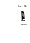
OVERVIEW
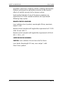
OVERVIEW
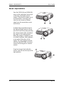
MGP D5
A
Focus ring
B
Zoom ring
C
IR sensor
D
Ventilation
E
Keypad
F
Connector panel
G
Power connector
H
Lamp house
I
Adjustable foot
J
Foot release
K
Security lock
L
Ceiling mount
9
KEYPAD
User Guide
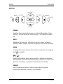
KEYPAD
VOLUME +
SOURCE
MENU
SOURCE
POWER
AUTO
STATUS
VOLUME –
POWER
Switches the projector between on and standby modes. Press
firmly (1 sec) to switch on. Press firmly (1 sec) twice to switch
off.
AUTO
Adjusting the projector to display a correct image, including
position, width, height, contrast, brightness and overall stability.
MENU
Activates the menu system. Use the four arrow keys to navigate
and
to activate.
/
Select menu option when menu system is activated. Activates
the keystone correction when the menu system is not in use. Use
the four arrow keys to adjust horizontally and vertically.
SOURCE
Use the two arrow keys to select source when keystone
correction and menu system is not activated.
10
MGP D5
User Guide
KEYPAD
VOLUME
Use the two arrow keys to adjust the sound volume.
STATUS
This is an indicator light, not a key. Do not push. It indicates the
current projector status. See STATUS chapter for detail.
MGP D5
11
STATUS
User Guide
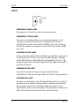
STATUS
POWER
STATUS
PERMANENT GREEN LIGHT
The projector is turned on and in normal operation.
PERMANENT YELLOW LIGHT
The unit is in standby mode; no source(s) connected, or the
source(s) connected are inactive or switched off, thereby
activating the power-save function (DPMS). You may enable or
disable the power save function in the SET UP sub menu, DPMS
on or off.
FLASHING YELLOW LIGHT
Please wait. The yellow light will flash a period after power cord
is connected (10-15 sec.), and a period after going to standby
mode while lamp is cooling down (approximately 45 sec.). The
projector may not be turned on again until the light has turned to
permanent yellow.
PERMANENT RED LIGHT
Lamp life has expired. Please change projection lamp
immediately. Failing to change lamp may lead to lamp explosion.
FLASHING RED LIGHT
Projector is overheated. Turn off immediately! Check if air inlets
are covered or if ambient temperature is outside specifications.
The projector can not be restarted unless the power cord is
disconnected and reconnected again. If the projector continues to
flash red, you will need to return the unit for service.
12
MGP D5
User Guide
REMOTE CONTROL
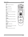
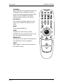
REMOTE CONTROL
The remote control allows flexible access to the projector
settings, either through direct keys, or through the menu system.
The remote control can be used to emulate the computer mouse
through the USB interface.
POWER
Switches the projector between on and
standby modes.
AUTO
Adjusting the projector to display a correct image, including position, width,
height, contrast, brightness and overall
stability.
OSD
Toggle On Screen Display (OSD) feedback
of and off. When on, all user commands
are echoed on screen. When off, user
commands will not be echoed on screen.
INFO
Displays source and projector status on
screen.
VIDEO
Selects the composite video input as signal source
S-VIDEO
Selects the super video input as signal
source
MGP D5
13
REMOTE CONTROL
User Guide
YPbPr
Selects component video input
DVI
Selects the DVI input
VGA 1
Selects the VGA 1 input
VGA 2
Selects the VGA 2 input
STILL
Toggles between live and still (frozen)
image
AV MUTE
Toggles between live and no (muted)
image
BRIGHT
Adjusts image brightness from dark to
bright
CONTRAST
Adjusts the image contrast from soft to
hard
COLOR
Adjusts the color of the image from pale
to saturated
VOLUME
Adjusts the sound volume
ASPECT
Cycles through the aspect ratios available
with the current source
MENU
Toggles the menu system on and off
14
MGP D5
User Guide
REMOTE CONTROL
TRACKBALL
When USB cable is connected between PC
and projector, the trackball is used to
move the mouse pointer when not in the
menu. Use the trackball to navigate
between options when in the menu.
LEFT/SELECT
Use as mouse LEFT key when not in the
menu. Use as SELECT key when in the
menu
RIGHT
Use as mouse RIGHT key
LASER
Activates the built-in laser pointer.
CAUTION! Do not point laser beam at people. Do not stare into laser beam.
ARROW KEYS
Use the four arrow keys as alternatives to
the trackball for menu navigation
SELECT
Select option in menu. Same function as
LEFT/SELECT above.
MGP D5
15
CONNECTOR PANEL
User Guide
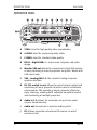
CONNECTOR PANEL
16
A
YPbPr: Used for high quality video reproduction.
B
S-VIDEO: Used for improved quality video.
C
C-VIDEO: Used for standard video quality.
D
DVI-D - Digital RGB: For a low noise computer and video
image.
E
Monitor VGA out: Allows for connection to local VGA monitor
or daisy-chaining of several projectors using VGA. Works with
VGA inputs only.
F
VGA - Analog RGB 1-2: The standard analog computer
graphics interface.
G
RS 232 control in-out: Allows for wired remote control and
monitoring of many projector functions used in installation
environments. The secondary output connector allows for
daisy-chaining, enabling both individual and global control
and monitoring of multiple projectors.
H
Audio in 1-2: Allows for connection of up to two audio
sources simultaneously.
I
Audio out: Connection to external audio system.
J
RC: Allows connection of external IR receiver or wired
remote control.
MGP D5
User Guide
MGP D5
CONNECTOR PANEL
K
USB - interface: Allows for computer mouse control.
L
LAN: Provides access to control and monitoring over a Local
Area Network.
M
Mains power connector: Use only three-prong, grounded
power cord.
17
SET UP VIDEO
User Guide
SET UP VIDEO
Before setting-up, switch off all equipment.
Three video sources may be connected, using the YPbPr
(component), S-VIDEO (super video) and VIDEO (composite video)
inputs.
Component video will display more detailed images. Composite
video yields images with less detail.
In addition, the DVI-D input can be used with video sources (DVD
player fitted with an HDCPTM compliant DVI or HDMI connector) for
a pure digital connection.
Connect the power cord.
18
MGP D5
User Guide
SETUP COMPUTER
SETUP COMPUTER
Before setting-up, switch off all equipment.
The projector may be connected to up to three computer sources
simultaneously, using the VGA and DVI inputs.
The VGA interface is analog and may cause some noise in the
projected image, depending on the signal quality from the VGA
graphics card in the computer.
The DVI (Digital Visual Interface) interface is all-digital and will
yield a projected image with very low noise.
Connect the USB cable to allow for remote mouse control.
Connect the power cord.
Connect the RS232 interface to allow for individual or global
control of multiple units in a daisy chain configuration.
Connect the LAN connector for individual control and monitoring
of multiple projectors over LAN.
MGP D5
19
IMAGE ADJUSTMENTS
User Guide
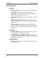
IMAGE ADJUSTMENTS
Turn the FOCUS (A) and ZOOM (B)
rings on the projection lens to get
a correctly sized and focused
image. If the desired image size is
not achieved by zooming, relocate the unit nearer or farther
away from the projection screen
and refocus.
To adjust the projected image to
the desired height on the screen,
eject the front foot (C) by pressing
the release button (D), and adjust
the angle to the right position.
When the image is shifted up, the
so-called 'keystone' effect appears
as an optical distortion of the
image. You may compensate this
effect by the KEYSTONE correction
control on the keypad or remote
control.
To get an image level with the
screen, turn the rear feet (E) to the
right position.
20
MGP D5
User Guide
CEILING MOUNT (option)
CEILING MOUNT (option)
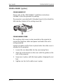
CEILING MOUNT KIT
Please refer to the “MSP-BAR034” installation instructions
included in the ceiling mount kit package.
The projector is provided with 3 threaded inserts (L) to attach the
UPA interface bracket of the ceiling mount kit.
CEILING MOUNT COVER
The auxiliary cable cover can be mounted on the projector to
conceal the interface cables and power cord when the unit is
ceiling mounted.
Connect all cables and fix them in place before the cable cover is
attached to the projector.
MGP D5
1.
Loosen the rear adjustable feet by unscrewing them.
2.
Align the vertical hooks on the cover with the guides on the
rear of the projector.
3.
Snap cover in place, with the lower guides clamping the rear
feet.
4.
Tighten rear feet to fix cable cover in place.
21
CEILING MOUNT (option)
22
User Guide
MGP D5
User Guide
USING THE PROJECTOR
USING THE PROJECTOR
After setting-up, switch on all equipment.
To switch the projector on, firmly press the POWER button on the
keypad or the remote control. The STATUS indicator will turn from
yellow to green when the unit is switched on.
If the STATUS indicator is flashing yellow, please wait until it turns
permanent yellow.
When only one source is connected, the projector will autodetect that source. If more sources are connected, the projector
will search for the next active source according to the following
list, provided that SOURCE SCAN is set to ON in the SET UP sub
menu (see description of menu system):
• VGA 1
• VGA 2
• DVI-D
• Component
• S-Video
• Composite Video
Select between the sources by pressing the SOURCE buttons on
the keypad or the remote control. Only sources that are active
will be displayed.
If no source is active, searching messages will appear on the
screen.
If no source is active for a long time, the projector will go in
standby mode if DPMS (power save) is set to ON in the SET UP
sub menu. The STATUS indicator will turn from green to flashing
yellow, then yellow. The projector will be switched back on if at
least one source is (re)activated. The power-down function can
be disabled in the menu. See DPMS in the SET UP sub menu.
To switch the projector off, firmly press the POWER button on the
keypad or the remote control twice (to confirm that you really
MGP D5
23
USING THE PROJECTOR
User Guide
want to switch off the unit). The STATUS indicator will turn from
green to flashing yellow, then yellow when switched off.
You may not switch the unit on while the STATUS indicator is
flashing yellow. Please wait until the indicator is permanent
yellow.
24
MGP D5
User Guide
MENU SYSTEM
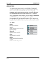
MENU SYSTEM
The menu system gives access to a multitude of image and
system controls. The menu system is structured through a top
menu and several sub menus. The sub menus may vary
depending on the actual source selected. Also, some functions
are not available when the DICOM display curve is selected.
When accessing the menu system, you will enter at the position
you left last time you were using the menu system.
Press the MENU key and navigate using the arrow keys on the
keypad or the trackball or the arrow keys on the remote control
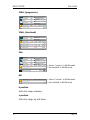
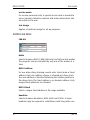
TOP MENU
picture
Basic picture controls
dynamic
Allows additional control over the
projected image.
advanced
Advanced picture controls
set up
General projector controls
picture
dynamic
advanced
setup
utilities
control
utilities
System controls and information
control
RS232 and LAN configurations
MGP D5
25
MENU SYSTEM
User Guide
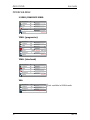
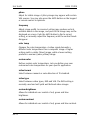
PICTURE SUB MENU
S-VIDEO/COMPOSITE VIDEO
brightness
50
contrast
50
color
50
tint
50
sharpness
3
aspect
fill 16:9
YPbPr (progressive)
brightness
50
contrast
50
color
50
hue
50
space
sharpness
SMPT REC601 REC709
3
aspect
fill 16:9
YPbPr (interlaced)
brightness
50
contrast
50
color
50
tint
50
sharpness
3
aspect
fill 16:9
VGA
brightness
40
contrast
70
sharpness
3
aspect
26
} Not available in DICOM mode
fill aspect ratio
MGP D5
User Guide
MENU SYSTEM
DVI
brightness
50
contrast
50
sharpness
3
aspect
} Not available in DICOM mode
fill aspect ratio
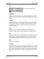
brightness
Adjusts the image brightness. A higher setting will increase the
brightness, a lower setting will decrease the brightness of the
image.
contrast
Controls the contrast of the image. A higher setting will yield a
'harder' image with larger difference between shades, while a
low setting will produce a 'softer' image with less difference
between shades.
color
Adjusts the color saturation. A higher setting will produce
stronger coloring, while a lower setting will yield paler colors.
tint
Adjusts the NTSC color tint. Applicable to NTSC (American) video
standard only. A higher setting will yield a more reddish color
scheme, while a lower setting will turn colors more greenish.
hue
Controls the color hue
sharpness
Controls the image sharpness. A higher setting will yield a harder
image, with less filtering. In video applications, this may produce
more noise in the projected image. A lower setting will soften
the image, looking more smeared out, and reducing the overall
noise.
MGP D5
27
MENU SYSTEM
User Guide
aspect
Selects image format. An image may be displayed in various
aspect ratios. This function is used when displaying source
formats that differ from the projectors native display format.
space
Defines the color standard used for component video so that the
image is displayed with the proper characteristics.
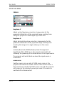
DYNAMIC SUB MENU
FOR ALL INPUTS
white boost
10
gamma
computer 2
eco mode
lamp power
lamp runtime:
DICOM
on
} Not available in DICOM mode
off
10
27 hrs
off
white boost
Increases the white level of the image for enhanced contrast
gamma
The source image is adapted to characteristics typical to certain
applications. This enables an optimized display of images,
depending on whether the source is video, computer etc.
eco mode
Reducing lamp power for maximum lamp life and reduced power
consumption
lamp power
Allows for continuously adjustable lamp power for easier
calibration of multiple-screen set-ups.
28
MGP D5
User Guide
MENU SYSTEM
lamp runtime
The total time the lamp has been operating since the projector
was produced or the lamp was replaced, if the lamp counter was
reset after replacement.
DICOM
Allows to select a DICOM display function, which optimizes the
projector to the DICOM standard.
You can select from 4 DICOM display functions:
•
Clearbase:
DICOM clearbase color temperature
•
Clearbase boost:
DICOM clearbase color temperature with increased white
level
•
Full white:
DICOM native projector white color temperature
•
Full white boost:
DICOM native projector white color temperature with
increased white level
ADVANCED SUB MENU
S-VIDEO/COMPOSITE VIDEO
H position
50
V position
50
color temp
6500 7300 9300 custom
custom color
video format auto NTSC PAL SECAM
video type
MGP D5
DVD
VCR
29
MENU SYSTEM
User Guide
YPbPr (progressive)
H position
50
V position
50
Phase
4
864
frequency
color temp 6500 7300 9300 custom
custom color
YPbPr (interlaced)
H position
50
V position
50
color temp
6500 7300 9300 custom
custom color
video format auto NTSC PAL SECAM
video type
DVD
VCR
VGA
H position
50
V position
50
phase
frequency
4
1688
color temp 6500 7300 9300 custom
custom color
full auto image
-> Always “custom” in DICOM mode
-> Not available in DICOM mode
press
DVI
color temp 6500 7300 9300 custom
custom color
-> Always “custom” in DICOM mode
-> Not available in DICOM mode
h position
Shifts the image sideways.
v position
Shifts the image up and down.
30
MGP D5
User Guide
MENU SYSTEM
phase
Adjust for stable image. A jittery image may appear with certain
VGA sources. You may also press the AUTO button on the keypad
or remote control to optimize.
frequency
Adjust image width. An incorrect setting may produce vertical,
unstable bands in the image, and parts of the image may not be
displayed on screen. Push the AUTO button to find a correct
setting, or manually adjust the frequency until the vertical bands
disappear.
color temp
Changes the color temperature. A video signal demands a
different color temperature than a computer image. A higher
setting yields a colder (bluer) image, while a lower setting
produces a warmer (more yellow) image.
custom color
Defines custom color temperature. Lets you define your own
customized color temperature for your specific application.
video format
Select between manual or auto detection of TV standard.
video type
Select between video types; DVD and VCR. The DVD setting is
normally used and will yield well defined video images.
custom brightness
Allows for individual user control of red, green and blue
brightness.
custom contrast
Allows for individual user control of red, green and blue contrast.
MGP D5
31
MENU SYSTEM
User Guide
full auto image
Adjusts h and v position, phase and frequency automatically.
Important: you must perform the full auto image function on a
good test pattern. Otherwise, the image may not be correctly
adjusted. Therefore, to perform the full auto image function
correctly, run the calibration wizard in the TheaterWatch
software application.
32
MGP D5
User Guide
MENU SYSTEM
SET UP SUB MENU
FOR ALL
keystone V
0
keystone H
0
DPMS
on
off
source scan
on
off
orientation
desktop front
OSD
language
RGB Video
off
keystone V
Adjust vertical keystone correction. Compensates for the
geometrical distortion of the projected image resulting from
tilting the projector to shoot higher up on the wall.
keystone H
Adjust horizontal keystone correction. Compensates for the
geometrical distortion of the projected image resulting from
shooting the image at an angle sideways on the screen.
DPMS
Activate/deactivate DPMS (Display Power Management
Signalling). When DPMS is on, the projector will switch off
following the powering off or disconnection of the signal source.
The projector will switch back on when the signal source is
reactivated.
source scan
Switches source scan on and off. With source scan on, the
projector will search for another source if the current source is
disconnected or switched off. With source scan off, the projector
will remain at the selected source input even if the source is
switched off or disconnected.
MGP D5
33
MENU SYSTEM
User Guide
orientation
Select between desktop front, desktop rear, ceiling front and
ceiling rear mode. The image will be flipped and reversed
accordingly.
OSD
Select where to have the On Screen Display
language
Select between languages
RGB video
Selects RGB video on the component video input (YPbPr).
Requires composite sync connected to the composite video input.
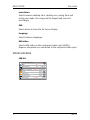
UTILITIES SUB MENU
FOR ALL
press
system information
OSD
on
off
OSD timeout
50
seconds
OSD background opaque translucent
reset
press
lamp reset
press
service menu
test image
34
press
hide
show
MGP D5
User Guide
MENU SYSTEM
SYSTEM INFORMATION
system information
source:
s-video
brightness:
50
format:
576p PAL
contrast:
47
mode:
69
color:
40
software:
0034-01.06
sharpness:
3
lamp remaining: 1999:44
gamma:
film 1
black level:
0
color temp:
6500K
White boost:
0
MAC:
00-00-00-00-00-00
IP address:
0.0.0.0
subnet:
0.0.0.0
gateway:
0.0.0.0
TCP port:
0
UDP port:
0
information
Displays information about the source and projector status
OSD
Turn the On Screen Display on (display) or off (hide) during
source scan.
OSD timeout
Defines how long OSD is displayed after last key action before it
disappears from the screen.
OSD background
Select background mode, whether transparent or opaque.
reset
Resets the projector to its basic settings. All parameters available
in the various menus are reset to their factory values.
lamp reset
Reset lamp after lamp change. Do not reset lamp counter unless
the lamp has been replaced with an original new lamp.
MGP D5
35
MENU SYSTEM
User Guide
service menu
For service personnel only. A special service code is needed to
access internal calibration controls and status information. Not
accessible to the user.
test image
Applies a fixed test image for set-up purposes
CONTROL SUB MENU
FOR ALL
RS232
mode
auto
fixed
232
RS232 Address
232
RS232 Fixed
1
232
baudrate
19200
Mode
Selects between RS232, RIMI (internal) and LAN control modes.
The projector can be controlled by only one of the modes at a
time.
RS232 address
For use when daisy-chaining several units. Select auto or fixed
address. Only one address scheme is allowed per daisy-chain.
The auto address is allocated following the relative position in
the daisy-chain. The fixed address is an absolute address. Only
unique fixed addresses are allowed.
RS232 fixed
Select a unique fixed address in the range available.
baudrate
Selects between baudrates 4800, 9600 and 19200. A lower
baudrate may be required in installations with long cable runs.
36
MGP D5
User Guide
MOUSE CONTROL
MOUSE CONTROL
You may control the computer mouse functions using the remote
control.
In order to enable this function, connect a USB cable between the
computer and the projector. Ensure that the PC has an operating
system that supports USB (Windows™ 98 2nd edition or newer).
As long as the menu system on the projector is not activated, the
tracker ball on the remote control will now emulate the mouse
movements. When the menu system is activated, the tracker ball
is used for menu navigation. (See menu system chapter).
Point the remote control directly at the IR receiver in the front or
in the rear. Move the mouse pointer by rolling the tracker ball in
the direction required. The LEFT key emulates the left mouse key,
while the RIGHT key emulates the right mouse key.
The pointer movement may not be as smooth as you are used to
with you ordinary mouse, due to the reduced bandwidth of the
infrared remote control connection.
MGP D5
37
RS 232 AND LAN CONTROL
User Guide
RS 232 AND LAN CONTROL
RS 232
You may control and monitor the projector remotely through the
serial RS232 control interface.
The RS232 protocol is a binary protocol where each command is a
series of 32 bytes in one packet. The protocol allows for both SET
and GET operations. To utilize GET operations the host needs a
routine for receiving and interpreting incoming packets. SEToperations are used to force the projector into different modes,
like setting brightness and contrast, switching between sources,
etc.
A separate document “RS-232 and LAN communication protocol
and command set” is available that describes the
communications parameters and operational codes in detail.
LAN
The projector can be controlled and monitored using through the
LAN connector as an alternative to RS232.
LAN control is based on the same command set as RS232.
NOTE! THE PROJECTOR IS CONFIGURED WITH A DEFAULT IP ADDRESS.
SEE THE SYSTEM INFORMATION AVAILABLE THROUGH THE MENU
SYSTEM OR REMOTE CONTROL FOR THE ACTUAL IP-ADDRESS.
Detailed descriptions of configuration, use and command set is
described in a separate document “RS-232 and LAN
communication protocol and command set”.
You may consider using the LAN interface as a means of theftdetection. When the projector is removed, the LAN will be
disconnected; this may be detected over the local area network
and could be used to trigger an alarm.
38
MGP D5
User Guide
TROUBLESHOOTING
TROUBLESHOOTING
NO IMAGE
No connection: Check if all connections are properly made.
Source off: Check if the equipment is powered on.
Lamp dead: The lamp may need replacement. Check the
LAMP TIME in the UTILITIES sub menu.
Source hibernated: Engage the source to display and active
image.
Notebook external screen: Different notebook PC's use
different combinations of keystrokes to enable the external
graphics port.
Source scan off: Check SOURCE SCAN in the SET UP sub
menu. If setting is OFF, the projector will not search for the
next active source, but will remain with the current source
selected.
DARK IMAGE
Old, worn lamp: The lamp may need replacement. Check
the LAMP TIME in the UTILITIES sub menu.
Low BRIGHTNESS and CONTRAST settings: Press AUTO or
use the menu system, PICTURE sub menu for CONTRAST and
BRIGHTNESS adjustment.
FLICKERING IMAGE
Bad lamp: Replace the lamp. Check the LAMP TIME in the
UTILITIES sub menu.
MGP D5
39
TROUBLESHOOTING
User Guide
UNSHARP IMAGE
Keystone correction may have been activated inadvertently:
compressing parts of the image that affect the display of
fine-line graphics, text and other images of high resolution.
Source resolution is different from projectors native
resolution: The projector will automatically scale and resize
the input format to its native resolution. Use a different
scaling factor in the PICTURE sub menu, ASPECT. You may also
adjust the SHARPNESS.
40
MGP D5
User Guide
MAINTENANCE
MAINTENANCE
The projector may from time to time need cleaning. Never open
the unit, as this will void any warranties. Refer service and repair
to qualified personnel only.
The projector is using a lamp that has a limited life time. Please
refer to the LAMP CHANGE section below for further details.
Only the exterior of the unit may be cleaned. Use a damp cloth.
Make sure no liquids enter the inside of the projector
Vacuum clean all the air vents (A) regularly to maintain sufficient
air flow.
The projection lens (B) is sensitive to scratches. Use lens cleaning
tissue, available at all photographic stores when cleaning the
projection lens. Use lens cap when not in use.
MGP D5
41
MAINTENANCE
User Guide
HEAVY DUTY AND CONTINOUS USE
The projector contains moving parts (such as cooling fans) that
have limited life-expectancies. When the projector has been used
for 7 500 hours, and when the unit is applied to mission-critical
use, it is recommended that the projector is given preventive
maintenance by a qualified service person. This will help ensure
long term stable operation.
42
MGP D5
User Guide
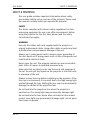
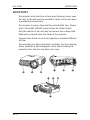
LAMP CHANGE
LAMP CHANGE
The STATUS lamp on the keypad will turn
red when the lamp life expires. In addition,
a message will appear on the screen:
“LAMP LIFE TIME HAS EXPIRED! Please
change lamp!”
POWER
STATUS
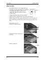
Change the lamp when lifetime expires.
Always replace lamp with the same type and rating.
Always disconnect the power cord and wait until the projector
has cooled down (60 minutes) before opening the lamp cover
(B).
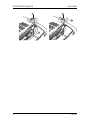
Release the screw (A).
Remove the lamp cover (B).
Release the screws on the lamp
house (C).
Pull the handle (D).
MGP D5
43
LAMP CHANGE
User Guide
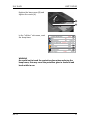
Remove the lamp house (E).
Replace with a new lamp in reverse order.
Replace the lamp house (E) and
tighten the screws (C).
Fold the handle (D) in place.
44
MGP D5
User Guide
LAMP CHANGE
Replace the lamp cover (B) and
tighten the screw (A).
In the “utilities” sub menu, reset
the lamp timer.
press
system information
OSD
on
off
OSD timeout
50
seconds
OSD background opaque translucent
reset
press
lamp reset
press
service menu
test image
press
hide
show
WARNING
Be careful not to touch the protective glass when replacing the
lamp house, this may cause the protective glass to overheat and
break while in use.
MGP D5
45
SERVICE INFORMATION
User Guide
SERVICE INFORMATION
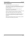
This product contains no user serviceable parts.
If the product fails to function as expected, please first check that
all connections are properly made, and that the power cord is
properly connected.
Please check that the projector as well as the video and
computer sources are all switched on.
Cables and cords may break over time. Try to change cables and
cords, in case there is a bad or intermittent connection.
Check if the circuit breaker or fuse of your mains is intact.
In the event of product failure, please contact your reseller. You
should prepare a description of the symptoms of failure you
experience.
Please also state product number and serial number as printed
on the label on the bottom of the projector.
46
MGP D5
User Guide
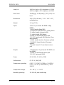
TECHNICAL DATA
TECHNICAL DATA
Resolution
1400 x 1050 (native) SXGA+
Display technology
Single chip DLP™ technology by Texas
Instruments
Display device
LVDS DMD™ with DarkChip2™ technology
Computer Compatibility
UXGA, SXGA+, SXGA, XGA, SVGA, VGA
PC, MAC, SGI and other workstations
RGBHV, RGBS, RGsB
Video Compatibility
HDTV (1080i, 720p, 576i/p, 480i/p)
NTSC, NTSC 4.43, PAL, PAL-M, PAL-N, SECAM.
Faroudja™ de-interlacing with automatic
film mode detection (3 : 2 and 2 : 2 pulldown)
Aspect Ratio
4 : 3 (native), 16 : 9 / 5 : 4 (compatible)
Bandwidth
Up to 205 MHz on analog RGB
Up to 160 MHz on DVI
Up to 75 MHz on component input
Brightness
2500 ANSI lumen (typ), 2200 ANSI lumen
(min) @ 250W lamp power*)
2000 ANSI lumen (typ), 1750 ANSI lumen
(min) @ ECO-mode 200W lamp power*)
*) Initial brightness.
MGP D5
Contrast
2000 : 1 B/W (typ), 1500 : 1 B/W (min)
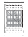
Zoom lens
f = 33 - 42
F = 2.75 - 3.1
Zoom factor = x 1.25
throw ratio = 1.70 - 2.2 : 1 (distance :
width)
throw distance = 1.5 m - 10 m / 5 - 33 ft.
image width = 0.7 m - 5.7 m / 2.3 - 18.8 ft.
offset = 108%
Lamp
250W UHP™ dimmable to 200W
47
TECHNICAL DATA
48
User Guide
Lamp Life
2000 hrs (typ) to 50% brightness @ 250W
4000 hrs (typ) to 50% brightness @ 200W
Noise level
28 dB (typ), 32 dB (max) @ 20°C/68°F, sea
level
Dimensions
244 x 278 x 88 mm / 9.6" x 10.9" x 3.5",
excluding lens
Weight
3.4 kg/7.5 lbs
Inputs
2 VGA 15 pin female HD-DSUB analog
RGBHV
1 DVI-D female digital RGB
1 Component video female 3 x RCA/phono
1 S-video female 4 pin mini-DIN
1 C-video female RCA/phono
2 Audio 3.5 mm female stereo jack
1 RS 232 9 pin female DSUB (control, firmware update)
1 USB-B female (control, firmware update)
1 LAN RJ-45 female (control, firmware
update)
1 Remote Control 3.5 mm female stereo
jack
Outputs
1 VGA Monitor 15 pin female HD-DSUB analog RGBHV
1 Audio 3.5 mm female stereo jack
1 RS 232 9 pin male DSUB
Power
90-260 VAC, 50-60 Hz, 350W
Conformance
CE, FCC A, CSA(C,US)
Temperature operating
0-40°C / 32-104°F, 0-1500 m / 0-4950 ft
0-35°C / 32-95°F, 1500-3000 m / 49509900 ft
Temperature storage
-20 - 60°C / -4 - 140°F
Humidity operating
20-90% RH, non-condensing
MGP D5
User Guide
Humidity storage
TECHNICAL DATA
10-95% RH, non-condensing
Specifications subject to change without prior notice. All values may vary
up to +/- 20%.
MGP D5
49
50
7.50
6.75
6.00
5.25
4.50
3.75
3.00
2.25
1.50
0.75
0
1.98
1.78
1.58
1.39
1.19
0.99
0.79
0.59
0.40
0.20
0.0
0.60
0.54
0.48
0.42
0.36
0.30
0.24
0.18
0.12
0.06
0
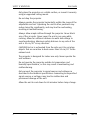
Accuracy: +/- 5%
m
0
2.48
4.95
7.43
9.90
12.38
14.85
17.33
19.80
22.28
24.75
ft
Image height
ft
m
Offset (8%)
0
0
3.30
1.00
Throw ratios SX+, zoom and fixed lenses
6.60
2.00
9.90
3.00
13.20
4.00
1
16.50
1 .7
0:
1
19.80
6.00
23.10
7.00
1
.2 :
ns 2
mle
Zoo
ns
ml e
Zoo
5.00
ed
Fix
:1
26.40
8.00
29.70
9.00
33 .00 ft
10.00 m
0
0
3.3
6.60
9.90
13.20
16.50
19.80
23.10
26.40
29.70
33.00
ft
0
1.25
2.50
3.75
5.00
6.25
7.50
8,75
10.00
11.25
12.50
m
0.0
4.13
8.25
12.38
16.50
20.63
24.75
28.88
33.00
37.13
41.25
ft
Screen diagonal
Projection distance
1.00
2.00
3.00
4.00
5.00
6.00
7.00
8.00
9.00
10.00
m
Image width
TECHNICAL DATA
User Guide
MGP D5
User Guide
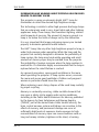
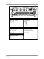
TECHNICAL DATA
G/Y
S-Video
PHONO/RCA FEMALE
4 PIN MINI DIN
FEMALE
1 GND
2 GND
3 Luma
4 Chroma
STEM GREEN: G/Y
SHIELD: GND
B/Pb
Composite Video
PHONO/RCA FEMALE
PHONO/RCA FEMALE
STEM BLUE: B/Pb
SHIELD: GND
STEM YELLOW: Composite
SHIELD: GND
R/Pr
PHONO/RCA FEMALE
STEM RED: R/Pr
SHIELD: GND
MGP D5
51
TECHNICAL DATA
52
User Guide
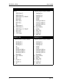
Computer DVI
Computer VGA 1
DVI-D
15 HIGH DENSITY DSUB FEMALE
1
2
3
4
5
6
7
8
9
10
11
12
13
14
1
2
3
4
5
6
7
8
9
10
11
12
13
14
15
TMDS Data 2TMDS Data 2+
TMDS Data 2/4 Shield
Not used
Not used
DDC Clock
DDC Data
NC
TMDS Data 1TMDS Data 1+
TMDS Data 1/3 Shield
Not used
Not used
+5V Power
Analog R in
Analog G in
Analog B in
AGND
AGND
Analog R GND in
Analog G GND in
Analog B GND in
Reserved
Sync GND in
AGND
DDC/SDA
H Sync in
V Sync in
DDC/SCL
Monitor VGA
Computer VGA 2
15 HIGH DENSITY DSUB FEMALE
15 HIGH DENSITY DSUB FEMALE
1
2
3
4
5
6
7
8
9
10
11
12
13
14
15
1
2
3
4
5
6
7
8
9
10
11
12
13
14
15
Analog R in
Analog G in
Analog B in
NC
AGND
Analog R GND in
Analog G GND in
Analog B GND in
Reserved
Sync GND in
NC
NC
H Sync in
V Sync in
NC
Analog R in
Analog G in
Analog B in
AGND
AGND
Analog R GND in
Analog G GND in
Analog B GND in
Reserved
Sync GND in
AGND
DDC/SDA
H Sync in
V Sync in
DDC/SCL
MGP D5
User Guide
TECHNICAL DATA
RS-232 in
RS-232 out
9 PIN DSUB FEMALE
9 PIN DSUB MALE
1
2
3
4
5
6
7
8
1
2
3
4
5
6
7
8
NC
RXD
TXD
NC
GND
NC
NC
NC
Audio out
RC in
Black
3.5 mm mini jack
3.5 mm stereo mini jack
TIP: R
STIM: L
RING: GND
TIP: 5V DC
RING: SIGNAL
STEM: GND
Audio in 1
Audio in 1
Black
3.5 mm mini jack
Black
3.5 mm mini jack
TIP: R
STIM: L
RING: GND
TIP: R
STIM: L
RING: GND
USB
LAN
DIGITAL USB
1
2
3
4
5
6
7
8
1
2
3
4
MGP D5
NC
TXD
RXD
NC
GND
NC
NC
NC
VCC
-Data
+Data
GND
TX+
TXRX+
GND
GND
RXGND
GND
53
DECLARATIONS
User Guide
DECLARATIONS
FCC
This equipment has been tested and found to comply with the
limits for a Class A digital device, pursuant to part 15 of the FCC
Rules. These limits are designed to provide reasonable protection
against harmful interference when the equipment is operated in
a commercial environment. This equipment generates, uses, and
can radiate radio frequency energy and, if not installed and used
in accordance with the instruction manual, may cause harmful
interference to radio communications. Operation of this
equipment in a residential area is likely to cause harmful
interference in which case the user will be required to correct the
interference at his own expense.
EN 55022 WARNING
This is a Class A product. In a domestic environment it may cause
radio interference, in which case the user may be required to
take adequate measures. The typical use is in a conference room,
meeting room or auditorium.
CANADA
This Class A digital apparatus complies with Canadian ICES-003.
CCet appareil numérique de la classe A est conforme à la norme
NMB-003 du Canada.
54
MGP D5