1
Allied Telesis™
AlliedView Network Management System 12.2
(SP2)
Administration Guide
Issue 2
Copyright © 2011 Allied Telesis, Inc. All rights reserved Information in this document is subject to change without notice.
613-001541 Rev B
Introduction to the AlliedView NMS Product
Congratulations on your purchase of the Allied Telesis™ Network Management System product. This
product allows administrators to query and control all aspects of Allied Telesis products in their network.
Who Should Read This Guide?
This document is for network administrators who need in-depth knowledge of the NMS and its applications.
Many of these applications are only available to administrators and allow them to control the actions
available to users. (Applications available to users are described in the NMS User Guide.)
About this Guide
This guide includes all aspects of the NMS product and includes information on the installation and
administration of the NMS server software.
•
Chapter 1 provides an overview of the product, how the document is organized, and the changes that have
occurred to both the product and this document since the last release.
•
Chapter 2 gives an overview of the installation process and starting up the client interfaces
•
Chapter 3 includes the real-time tasks available on the NMS (do not require a server restart).
•
Chapter 4 gives the tasks involved in setting up users and their scope of operation.
•
Chapter 5 includes the tasks available to control individual devices from both the Rapier and Telesis
families.
•
Chapter 6 controls how network-spanning features, such as interdevice VLANs, can be easily configured
using the AlliedView NMS user interface.
•
Chapter 7 includes all aspects of Provisioning Gateways (iMG/RGs)
•
Chapter 8 explains how statistics work and how to configure them.
•
Chapter 9 explains how the Fault Management application works and how to control alarm outputs.
•
Chapter 10 explains the html interface.
•
Chapter 11 explains the MIB manager interface.
Copyright © 2011 Allied Telesis, Inc. All rights reserved Information in this document is subject to change without notice.
•
Chapter 12 explains the capabilities of the Northbound interface.
•
The Appendix explains how to export to a file tabular data displayed in the Fault Management,
Performance, and Network Inventory views. For the iMG/RG, it includes sample configuration files.
Tracking Updates since the Previous Release
Section 1 of this document includes a Reason for Update table, allowing the user to see what features have
been added or changed. Throughout this document, change bars let the user know where the information
oscillated with these changes is located.
There is also an improved explanation for how standard and custom downloads are performed on the NMS.
Reason for Update
This document is being updated to include changes that are part of Release 12.0 SP2 and 12.0 SP2.1, as well
as technical updates.
Service and Support
For information about support services for Allied Telesis, contact your Allied Telesis sales representative or
visit the website at www.alliedtelesis.com.
All company names, logos, and product designs that are trademarks or registered trademarks are the property
of their prospective owners.
Copyright © 2011 Allied Telesis, Inc. All rights reserved Information in this document is subject to change without notice.
Copyright © 2011 Allied Telesis, Inc. All rights reserved Information in this document is subject to change without notice.
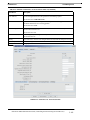
Table of Contents
1 Product Overview - - - - - - - - - - - - - - - - - - - - - - - - - - - - - -1-1
1.1 Intended Audience for this Guide - - - - - - - - - - - - - - - - - - - - - - - - - - - - - - - - - - - - - - 1-1
1.2 How this Document is Organized- - - - - - - - - - - - - - - - - - - - - - - - - - - - - - - - - - - - - - - 1-1
1.3 Reason for Update - - - - - - - - - - - - - - - - - - - - - - - - - - - - - - - - - - - - - - - - - - - - - - - - - 1-2
1.4 The AlliedView Network Management System (NMS)- - - - - - - - - - - - - - - - - - - - - - - 1.4.1 User Privileges at the NMS and Product Level - - - - - - - - - - - - - - - - - - - - - - - - - 1.4.2 Compatibility of NMS and Device Loads - - - - - - - - - - - - - - - - - - - - - - - - - - - - - 1.4.3 Setting Web Browser Caching - - - - - - - - - - - - - - - - - - - - - - - - - - - - - - - - - - - - 1.4.4 Using Default Prompt for Device Account Used by AlliedView NMS - - - - - - - - - -
1-6
1-6
1-7
1-7
1-7
1.5 Levels of Support (Enterprise Edition)- - - - - - - - - - - - - - - - - - - - - - - - - - - - - - - - - - - 1-8
1.6 .Managed Devices (Firmware Interop) - - - - - - - - - - - - - - - - - - - - - - - - - - - - - - - - - - - 1-9
1.6.1 Full Support, Excluding iMG/RG - - - - - - - - - - - - - - - - - - - - - - - - - - - - - - - - - - - 1-9
1.6.2 Basic Management Support - - - - - - - - - - - - - - - - - - - - - - - - - - - - - - - - - - - - - - 1-14
1.6.3 iMG/RG Types Supported (Including Devices that Support 3-8-02) - - - - - - - - - - - 1-16
1.7 Levels of Support - - - - - - - - - - - - - - - - - - - - - - - - - - - - - - - - - - - - - - - - - - - - - - - - 1.7.1 Overview - - - - - - - - - - - - - - - - - - - - - - - - - - - - - - - - - - - - - - - - - - - - - - - - - 1.7.2 Allied Telesis, AlliedWare, and AlliedWare Plus Products - - - - - - - - - - - - - - - - 1.7.3 AR, AT, and GenBand Products - - - - - - - - - - - - - - - - - - - - - - - - - - - - - - - - - - 1.7.4 Specific Market Devices - - - - - - - - - - - - - - - - - - - - - - - - - - - - - - - - - - - - - - - -
1-17
1-17
1-17
1-19
1-21
1.8 Document Conventions- - - - - - - - - - - - - - - - - - - - - - - - - - - - - - - - - - - - - - - - - - - - - 1-24
1.9 How to Use Supporting Documents - - - - - - - - - - - - - - - - - - - - - - - - - - - - - - - - - - - 1.9.1 Document Media - - - - - - - - - - - - - - - - - - - - - - - - - - - - - - - - - - - - - - - - - - - - 1.9.2 Printing Hardcopy - - - - - - - - - - - - - - - - - - - - - - - - - - - - - - - - - - - - - - - - - - - 1.9.3 Accessing Online - - - - - - - - - - - - - - - - - - - - - - - - - - - - - - - - - - - - - - - - - - - - 1.9.4 Using Online Help with NMS - - - - - - - - - - - - - - - - - - - - - - - - - - - - - - - - - - - -
1-24
1-24
1-24
1-24
1-24
1.10 Copyrights - - - - - - - - - - - - - - - - - - - - - - - - - - - - - - - - - - - - - - - - - - - - - - - - - - - - - 1-24
2 Installing and Starting Up - - - - - - - - - - - - - - - - - - - - - - - -2-1
2.1 Overview - - - - - - - - - - - - - - - - - - - - - - - - - - - - - - - - - - - - - - - - - - - - - - - - - - - - - - - - 2-1
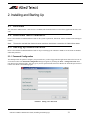
2.2 AlliedView NMS Installation- - - - - - - - - - - - - - - - - - - - - - - - - - - - - - - - - - - - - - - - - - 2-1
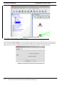
2.3 Starting up AlliedView NMS - - - - - - - - - - - - - - - - - - - - - - - - - - - - - - - - - - - - - - - - - - 2-1
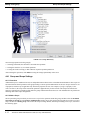
2.3.1 Password Configuration - - - - - - - - - - - - - - - - - - - - - - - - - - - - - - - - - - - - - - - - - 2-1
2.3.2 Configuration Limits for Clients - - - - - - - - - - - - - - - - - - - - - - - - - - - - - - - - - - - - 2-2
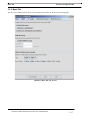
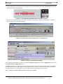
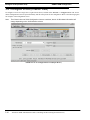
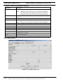
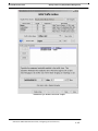
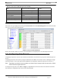
2.4 Using the Logs Console- - - - - - - - - - - - - - - - - - - - - - - - - - - - - - - - - - - - - - - - - - - - - - 2-2
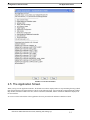
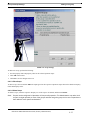
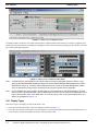
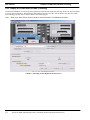
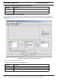
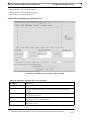
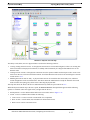
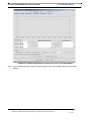
2.5 The Application Screen- - - - - - - - - - - - - - - - - - - - - - - - - - - - - - - - - - - - - - - - - - - - - - 2-3
2.6 Broadcasting a Message - - - - - - - - - - - - - - - - - - - - - - - - - - - - - - - - - - - - - - - - - - - - - 2-4
2.7 Restart / Shut Down the Server - - - - - - - - - - - - - - - - - - - - - - - - - - - - - - - - - - - - - - - - 2-5
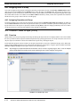
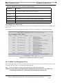
2.8 Resource Management - - - - - - - - - - - - - - - - - - - - - - - - - - - - - - - - - - - - - - - - - - - - - - 2-6
2.8.1 Setting the Custom Security Policy (Required) - - - - - - - - - - - - - - - - - - - - - - - - - - 2-6
AlliedView NMS Administration Guide (Table of Contents)
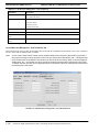
2.8.2 Resource Management Table (Tools -> Resource Management) - - - - - - - - - - - - - - -2-7
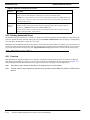
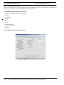
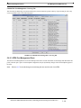
2.8.3 Front-End Monitor - - - - - - - - - - - - - - - - - - - - - - - - - - - - - - - - - - - - - - - - - - - - -2-7
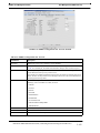
2.8.4 Client Memory Monitor - - - - - - - - - - - - - - - - - - - - - - - - - - - - - - - - - - - - - - - - - -2-7
3 File Administration - - - - - - - - - - - - - - - - - - - - - - - - - - - - 3-1
3.1 Overview - - - - - - - - - - - - - - - - - - - - - - - - - - - - - - - - - - - - - - - - - - - - - - - - - - - - - - - -3-1
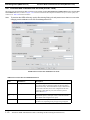
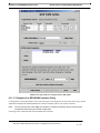
3.2 Discovery Configurator (Service Provider) - - - - - - - - - - - - - - - - - - - - - - - - - - - - - - - -3-3
3.2.1 Overview - - - - - - - - - - - - - - - - - - - - - - - - - - - - - - - - - - - - - - - - - - - - - - - - - - - -3-3
3.2.2 Schedule Tab - - - - - - - - - - - - - - - - - - - - - - - - - - - - - - - - - - - - - - - - - - - - - - - - -3-3
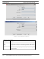
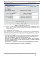
3.2.3 SNMP Tab - - - - - - - - - - - - - - - - - - - - - - - - - - - - - - - - - - - - - - - - - - - - - - - - - - -3-4
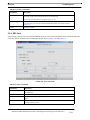
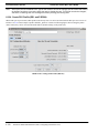
3.2.4 CLI Logins Tab - - - - - - - - - - - - - - - - - - - - - - - - - - - - - - - - - - - - - - - - - - - - - - - -3-6
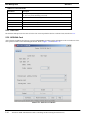
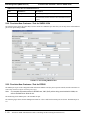
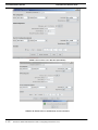
3.2.5 Network Discovery Tab - - - - - - - - - - - - - - - - - - - - - - - - - - - - - - - - - - - - - - - - - -3-8
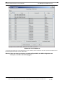
3.2.6 Node Discovery Tab - - - - - - - - - - - - - - - - - - - - - - - - - - - - - - - - - - - - - - - - - - - 3-10
3.2.7 Other Discovery Tab - - - - - - - - - - - - - - - - - - - - - - - - - - - - - - - - - - - - - - - - - - - 3-12
3.2.8 Example Configurations - - - - - - - - - - - - - - - - - - - - - - - - - - - - - - - - - - - - - - - - - 3-13
3.3 Discovery Configurator (EE) - - - - - - - - - - - - - - - - - - - - - - - - - - - - - - - - - - - - - - - - - 3-16
3.3.1 Overview - - - - - - - - - - - - - - - - - - - - - - - - - - - - - - - - - - - - - - - - - - - - - - - - - - - 3-16
3.3.2 Basic Tab - - - - - - - - - - - - - - - - - - - - - - - - - - - - - - - - - - - - - - - - - - - - - - - - - - - 3-17
3.3.3 SNMP Tabs - - - - - - - - - - - - - - - - - - - - - - - - - - - - - - - - - - - - - - - - - - - - - - - - - 3-19
3.3.4 CLI Logins Tab - - - - - - - - - - - - - - - - - - - - - - - - - - - - - - - - - - - - - - - - - - - - - - - 3-21
3.3.5 Network Discovery Tab - - - - - - - - - - - - - - - - - - - - - - - - - - - - - - - - - - - - - - - - - 3-23
3.3.6 Node Discovery Tab - - - - - - - - - - - - - - - - - - - - - - - - - - - - - - - - - - - - - - - - - - - 3-24
3.4 Backup and Restore - - - - - - - - - - - - - - - - - - - - - - - - - - - - - - - - - - - - - - - - - - - - - - - 3-25
3.4.1 AlliedView NMS Backup (On Demand) - - - - - - - - - - - - - - - - - - - - - - - - - - - - - - 3-25
3.4.2 AlliedView NMS Backup (Scheduled) - - - - - - - - - - - - - - - - - - - - - - - - - - - - - - - 3-26
3.4.3 Configuring Backup Parameters for AlliedView NMS- - - - - - - - - - - - - - - - - - - - - 3-28
3.4.4 Restore the AlliedView NMS (GUI Screens) - - - - - - - - - - - - - - - - - - - - - - - - - - - 3-28
3.4.5 Device Backup (Per-Device Limit)- - - - - - - - - - - - - - - - - - - - - - - - - - - - - - - - - - 3-32
3.5 AlliedView NMS License Manager - - - - - - - - - - - - - - - - - - - - - - - - - - - - - - - - - - - - - 3-33
3.5.1 Overview - - - - - - - - - - - - - - - - - - - - - - - - - - - - - - - - - - - - - - - - - - - - - - - - - - - 3-33
3.5.2 Installing a License (Using the License Key Manager) - - - - - - - - - - - - - - - - - - - - 3-33
3.5.3 Installing a License (Using the Console Mode) - - - - - - - - - - - - - - - - - - - - - - - - - 3-35
3.5.4 Verifying the License After Installation- - - - - - - - - - - - - - - - - - - - - - - - - - - - - - - 3-36
3.5.5 Viewing the License Configuration - - - - - - - - - - - - - - - - - - - - - - - - - - - - - - - - - 3-37
3.5.6 Migrating Existing Licenses - - - - - - - - - - - - - - - - - - - - - - - - - - - - - - - - - - - - - - 3-38
3.6 File Keys to Identify Downloadable Files- - - - - - - - - - - - - - - - - - - - - - - - - - - - - - - - - 3-40
3.6.1 Overview - - - - - - - - - - - - - - - - - - - - - - - - - - - - - - - - - - - - - - - - - - - - - - - - - - - 3-40
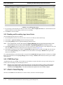
3.7 Log Files for Debugging the AlliedView NMS Server - - - - - - - - - - - - - - - - - - - - - - - - 3-41
3.8 Commands for the Allied Telesis Tools Submenu - - - - - - - - - - - - - - - - - - - - - - - - - - - 3-42
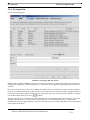
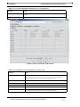
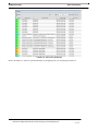
3.9 Status Monitoring - - - - - - - - - - - - - - - - - - - - - - - - - - - - - - - - - - - - - - - - - - - - - - - - - 3-43
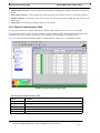
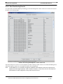
3.9.1 Status Table - - - - - - - - - - - - - - - - - - - - - - - - - - - - - - - - - - - - - - - - - - - - - - - - - 3-44
3.9.2 Menu Options (Export) - - - - - - - - - - - - - - - - - - - - - - - - - - - - - - - - - - - - - - - - - 3-48
3.10 Downloading Device Files- - - - - - - - - - - - - - - - - - - - - - - - - - - - - - - - - - - - - - - - - - - 3-49
3.10.1 Overview (Standard versus Custom Loads) - - - - - - - - - - - - - - - - - - - - - - - - - - - 3-49
3.10.2 Load Import GUI (Standard Loads) - - - - - - - - - - - - - - - - - - - - - - - - - - - - - - - - 3-49
3.11 Accessing the NMS Database - - - - - - - - - - - - - - - - - - - - - - - - - - - - - - - - - - - - - - - - 3-54
TOC-2
AlliedView NMS Administration Guide (Table of Contents)
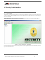
4 Security Administration- - - - - - - - - - - - - - - - - - - - - - - - - - 4-1
4.1 Overview - - - - - - - - - - - - - - - - - - - - - - - - - - - - - - - - - - - - - - - - - - - - - - - - - - - - - - - -4-1
4.2 Add a New User - - - - - - - - - - - - - - - - - - - - - - - - - - - - - - - - - - - - - - - - - - - - - - - - - - -4-3
4.3 User Settings- - - - - - - - - - - - - - - - - - - - - - - - - - - - - - - - - - - - - - - - - - - - - - - - - - - - - -4-6
4.3.1 Overview - - - - - - - - - - - - - - - - - - - - - - - - - - - - - - - - - - - - - - - - - - - - - - - - - - - -4-6
4.3.2 Associating Groups to User- - - - - - - - - - - - - - - - - - - - - - - - - - - - - - - - - - - - - - - -4-6
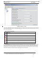
4.3.3 Setting User Profile - - - - - - - - - - - - - - - - - - - - - - - - - - - - - - - - - - - - - - - - - - - - -4-6
4.3.4 Viewing Audit Trails - - - - - - - - - - - - - - - - - - - - - - - - - - - - - - - - - - - - - - - - - - - -4-8
4.3.5 Change the User Password - - - - - - - - - - - - - - - - - - - - - - - - - - - - - - - - - - - - - - - -4-9
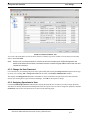
4.3.6 Assigning Operations to User - - - - - - - - - - - - - - - - - - - - - - - - - - - - - - - - - - - - - -4-9
4.3.7 Delete User - - - - - - - - - - - - - - - - - - - - - - - - - - - - - - - - - - - - - - - - - - - - - - - - - 4-10
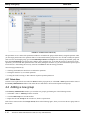
4.4 Adding a new group - - - - - - - - - - - - - - - - - - - - - - - - - - - - - - - - - - - - - - - - - - - - - - - 4-10
4.4.1 Group and Scope Settings - - - - - - - - - - - - - - - - - - - - - - - - - - - - - - - - - - - - - - - - 4-12
4.4.2 Assigning Users to Group - - - - - - - - - - - - - - - - - - - - - - - - - - - - - - - - - - - - - - - - 4-14
4.4.3 Assigning Operations to Group - - - - - - - - - - - - - - - - - - - - - - - - - - - - - - - - - - - - 4-14
4.5 Custom View Scope (CVS) - - - - - - - - - - - - - - - - - - - - - - - - - - - - - - - - - - - - - - - - - - - 4-14
4.5.1 Overview - - - - - - - - - - - - - - - - - - - - - - - - - - - - - - - - - - - - - - - - - - - - - - - - - - - 4-14
4.5.2 Add Authorized Scope for a Custom View Scope - - - - - - - - - - - - - - - - - - - - - - - - 4-15
4.5.3 Set Authorized Scope for a Custom View Scope- - - - - - - - - - - - - - - - - - - - - - - - - 4-15
4.5.4 Set Scope Properties - - - - - - - - - - - - - - - - - - - - - - - - - - - - - - - - - - - - - - - - - - - 4-15
4.5.5 Deleting Authorized Scope - - - - - - - - - - - - - - - - - - - - - - - - - - - - - - - - - - - - - - - 4-16
4.6 Permissions Tree - - - - - - - - - - - - - - - - - - - - - - - - - - - - - - - - - - - - - - - - - - - - - - - - - 4-16
4.6.1 Overview - - - - - - - - - - - - - - - - - - - - - - - - - - - - - - - - - - - - - - - - - - - - - - - - - - - 4-16
4.6.2 Permissions Tree - - - - - - - - - - - - - - - - - - - - - - - - - - - - - - - - - - - - - - - - - - - - - - 4-17
4.7 Remote Authorization (RADIUS / Tacacs+) on Devices - - - - - - - - - - - - - - - - - - - - - - 4-23
4.7.1 RADIUS - - - - - - - - - - - - - - - - - - - - - - - - - - - - - - - - - - - - - - - - - - - - - - - - - - - 4-23
4.7.2 Tacacs+ (Using the CLI Login Manager)- - - - - - - - - - - - - - - - - - - - - - - - - - - - - - 4-24
4.8 NMS RADIUS Client Support - - - - - - - - - - - - - - - - - - - - - - - - - - - - - - - - - - - - - - - - 4-25
4.8.1 Overview - - - - - - - - - - - - - - - - - - - - - - - - - - - - - - - - - - - - - - - - - - - - - - - - - - - 4-25
4.8.2 RADIUS Configurator Tool (with Valid License) - - - - - - - - - - - - - - - - - - - - - - - - 4-26
4.8.3 Example Configurations - - - - - - - - - - - - - - - - - - - - - - - - - - - - - - - - - - - - - - - - - 4-33
4.8.4 Feature Interactions (RADIUS Server De-activated or Unavailable) - - - - - - - - - - - 4-36
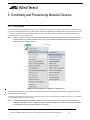
5 Controlling and Provisioning Network Devices - - - - - - - - - - 5-1
5.1 Overview - - - - - - - - - - - - - - - - - - - - - - - - - - - - - - - - - - - - - - - - - - - - - - - - - - - - - - - -5-1
5.2 View Chassis - - - - - - - - - - - - - - - - - - - - - - - - - - - - - - - - - - - - - - - - - - - - - - - - - - - - - -5-5
5.2.1 Display Types - - - - - - - - - - - - - - - - - - - - - - - - - - - - - - - - - - - - - - - - - - - - - - - - -5-6
5.2.2 Display of VLAN-based HVLANs (Tunneling) - - - - - - - - - - - - - - - - - - - - - - - - - -5-8
5.2.3 Notes on Chassis View - - - - - - - - - - - - - - - - - - - - - - - - - - - - - - - - - - - - - - - - - - -5-9
5.3 Provisioning a Device- - - - - - - - - - - - - - - - - - - - - - - - - - - - - - - - - - - - - - - - - - - - - - - -5-9
5.3.1 Overview of the Provisioning Interface - - - - - - - - - - - - - - - - - - - - - - - - - - - - - - - -5-9
5.3.2 Backup/Restore (with Purge Button)- - - - - - - - - - - - - - - - - - - - - - - - - - - - - - - - - 5-14
5.3.3 Command Script Management- - - - - - - - - - - - - - - - - - - - - - - - - - - - - - - - - - - - - 5-21
5.3.4 Configuration File Management - - - - - - - - - - - - - - - - - - - - - - - - - - - - - - - - - - - 5-27
5.3.5 Device Information - - - - - - - - - - - - - - - - - - - - - - - - - - - - - - - - - - - - - - - - - - - - 5-29
TOC-3
AlliedView NMS Administration Guide (Table of Contents)
5.3.6 SNMP Agent - - - - - - - - - - - - - - - - - - - - - - - - - - - - - - - - - - - - - - - - - - - - - - - - 5-30
5.3.7 SNMP Community - - - - - - - - - - - - - - - - - - - - - - - - - - - - - - - - - - - - - - - - - - - - 5-32
5.3.8 Obtaining SW Loads - - - - - - - - - - - - - - - - - - - - - - - - - - - - - - - - - - - - - - - - - - - 5-37
5.3.9 Software Configuration (Standard Loads) - - - - - - - - - - - - - - - - - - - - - - - - - - - - - 5-37
5.3.10 Software Configuration (Custom Loads) - - - - - - - - - - - - - - - - - - - - - - - - - - - - - 5-47
5.3.11 Using Custom Loads to Reduce Unneeded Card Types - - - - - - - - - - - - - - - - - - - 5-54
5.3.12 SysLog Management - - - - - - - - - - - - - - - - - - - - - - - - - - - - - - - - - - - - - - - - - - 5-56
5.3.13 LLDP Configuration - - - - - - - - - - - - - - - - - - - - - - - - - - - - - - - - - - - - - - - - - - 5-58
5.3.14 MPEG Test - - - - - - - - - - - - - - - - - - - - - - - - - - - - - - - - - - - - - - - - - - - - - - - - - 5-63
5.3.15 Using the Edit Functions- - - - - - - - - - - - - - - - - - - - - - - - - - - - - - - - - - - - - - - - 5-70
5.3.16 Using the Delete Function - - - - - - - - - - - - - - - - - - - - - - - - - - - - - - - - - - - - - - - 5-76
5.3.17 SNMPv3 USM Configuration - - - - - - - - - - - - - - - - - - - - - - - - - - - - - - - - - - - - 5-79
5.4 Configure VLAN (Chassis View) - - - - - - - - - - - - - - - - - - - - - - - - - - - - - - - - - - - - - - 5-80
5.5 Card Management - - - - - - - - - - - - - - - - - - - - - - - - - - - - - - - - - - - - - - - - - - - - - - - - 5-83
5.5.1 Overview - - - - - - - - - - - - - - - - - - - - - - - - - - - - - - - - - - - - - - - - - - - - - - - - - - - 5-83
5.5.2 Accessing the Card Management Application - - - - - - - - - - - - - - - - - - - - - - - - - - 5-84
5.5.3 Creating a Card (Pre-provisioning)- - - - - - - - - - - - - - - - - - - - - - - - - - - - - - - - - - 5-86
5.5.4 GE3 Card - - - - - - - - - - - - - - - - - - - - - - - - - - - - - - - - - - - - - - - - - - - - - - - - - - - 5-89
5.5.5 GE8 Card - - - - - - - - - - - - - - - - - - - - - - - - - - - - - - - - - - - - - - - - - - - - - - - - - - - 5-90
5.5.6 ADSL24A Card - - - - - - - - - - - - - - - - - - - - - - - - - - - - - - - - - - - - - - - - - - - - - - 5-90
5.5.7 ADSL24 (Annex B) and ADSL24AE - - - - - - - - - - - - - - - - - - - - - - - - - - - - - - - - 5-91
5.5.8 SHDSL24 Card (Card-Level vs. Port-Level) - - - - - - - - - - - - - - - - - - - - - - - - - - - 5-91
5.5.9 CFC24 Card in Simplex and Duplex- - - - - - - - - - - - - - - - - - - - - - - - - - - - - - - - - 5-91
5.5.10 CFC56, CFC100, and CFC200 Card - - - - - - - - - - - - - - - - - - - - - - - - - - - - - - - - 5-94
5.5.11 FE10/FX10 Card - - - - - - - - - - - - - - - - - - - - - - - - - - - - - - - - - - - - - - - - - - - - - 5-94
5.5.12 FX20 Card - - - - - - - - - - - - - - - - - - - - - - - - - - - - - - - - - - - - - - - - - - - - - - - - - 5-96
5.5.13 POTS24 Card - - - - - - - - - - - - - - - - - - - - - - - - - - - - - - - - - - - - - - - - - - - - - - - 5-96
5.5.14 CES8 Card - - - - - - - - - - - - - - - - - - - - - - - - - - - - - - - - - - - - - - - - - - - - - - - - 5-104
5.5.15 NTE8 Card - - - - - - - - - - - - - - - - - - - - - - - - - - - - - - - - - - - - - - - - - - - - - - - - 5-106
5.5.16 ADSL24A, ADSL24B, and ADSL24E Card - - - - - - - - - - - - - - - - - - - - - - - - - 5-107
5.5.17 PAC24A Card - - - - - - - - - - - - - - - - - - - - - - - - - - - - - - - - - - - - - - - - - - - - - - 5-107
5.5.18 EPON2 Card- - - - - - - - - - - - - - - - - - - - - - - - - - - - - - - - - - - - - - - - - - - - - - - 5-107
5.5.19 VDSL24 Card - - - - - - - - - - - - - - - - - - - - - - - - - - - - - - - - - - - - - - - - - - - - - - 5-107
5.5.20 ADSL48A/B Card - - - - - - - - - - - - - - - - - - - - - - - - - - - - - - - - - - - - - - - - - - - 5-107
5.5.21 Viewing Card Details for the iMAP 9100 - - - - - - - - - - - - - - - - - - - - - - - - - - - 5-107
5.5.22 GE24POE- - - - - - - - - - - - - - - - - - - - - - - - - - - - - - - - - - - - - - - - - - - - - - - - - 5-108
5.5.23 Controlling Card Software (Download and Restart)- - - - - - - - - - - - - - - - - - - - - 5-108
5.5.24 Overview of Provisioning Data, Profiles, and Card States - - - - - - - - - - - - - - - - 5-109
5.5.25 Power Over Ethernet (POE) Management on SBx3112 - - - - - - - - - - - - - - - - - - 5-110
5.5.26 XE Cards (XE1 and XE4) - - - - - - - - - - - - - - - - - - - - - - - - - - - - - - - - - - - - - - 5-111
5.5.27 GE24 Cards (GE24SFP, GE24POE, GE24RJ, GE24BX) - - - - - - - - - - - - - - - - - 5-112
5.6 Port Management (iMAP Devices) - - - - - - - - - - - - - - - - - - - - - - - - - - - - - - - - - - - - 5-112
5.6.1 Overview - - - - - - - - - - - - - - - - - - - - - - - - - - - - - - - - - - - - - - - - - - - - - - - - - - 5-112
5.6.2 Accessing the Port Management Application - - - - - - - - - - - - - - - - - - - - - - - - - - 5-112
5.6.3 Provision New Customer/Port (Triple Play Form) - with Preferences - - - - - - - - - - 5-115
5.6.4 Provision New Customer Port for Ethernet - - - - - - - - - - - - - - - - - - - - - - - - - - - 5-119
5.6.5 Provision New Customer/Port for ADSL- - - - - - - - - - - - - - - - - - - - - - - - - - - - - 5-119
5.6.6 Provision New Customer/Port for CES8 (DS1/E1 Form) - - - - - - - - - - - - - - - - - - 5-120
5.6.7 Provision New Customer/Port for NTE8 (DS1/E1 Form) - - - - - - - - - - - - - - - - - - 5-122
TOC-4
AlliedView NMS Administration Guide (Table of Contents)
5.6.8 Provision New Customer / Port for SHDSL16/24 - - - - - - - - - - - - - - - - - - - - - 5.6.9 Provision New Customer / Port for EPON2 - - - - - - - - - - - - - - - - - - - - - - - - - 5.6.10 Provision New Customer / Port for ONU - - - - - - - - - - - - - - - - - - - - - - - - - - 5.6.11 Provision New Customer / Port for VDSL24A/B - - - - - - - - - - - - - - - - - - - - - 5.6.12 Overview of Triple Play Service Management Form - - - - - - - - - - - - - - - - - - 5.6.13 Status Tab - - - - - - - - - - - - - - - - - - - - - - - - - - - - - - - - - - - - - - - - - - - - - - - 5.6.14 Add Derived Voice Line for GenBand (on Status Tab Form) - - - - - - - - - - - - - 5.6.15 iMG/RG Tab - - - - - - - - - - - - - - - - - - - - - - - - - - - - - - - - - - - - - - - - - - - - - 5.6.16 Ether-like Config. Tab (Upstream and Downstream) - - - - - - - - - - - - - - - - - - 5.6.17 ADSL Configuration Tab - - - - - - - - - - - - - - - - - - - - - - - - - - - - - - - - - - - - - 5.6.18 SHDSL Port Management Form - - - - - - - - - - - - - - - - - - - - - - - - - - - - - - - - 5.6.19 Voice Port Management (Tabbed Form) - - - - - - - - - - - - - - - - - - - - - - - - - - - 5.6.20 CES8 Port (DS1/E1 Port Management Tabbed Form)- - - - - - - - - - - - - - - - - - 5.6.21 NTE8 Port Management Form - - - - - - - - - - - - - - - - - - - - - - - - - - - - - - - - - 5.6.22 SHDSL Bonding (Card Level to Port Level) - - - - - - - - - - - - - - - - - - - - - - - - 5.6.23 View the EPON2 Port Configuration - - - - - - - - - - - - - - - - - - - - - - - - - - - - - 5.6.24 ONU Configuration (as ON1000 or as part of iMG646PX-ON) - - - - - - - - - - - 5.6.25 VDSL24 Port - - - - - - - - - - - - - - - - - - - - - - - - - - - - - - - - - - - - - - - - - - - - - 5.6.26 Statistics Tab - - - - - - - - - - - - - - - - - - - - - - - - - - - - - - - - - - - - - - - - - - - - - 5.6.27 Port Log Tab - - - - - - - - - - - - - - - - - - - - - - - - - - - - - - - - - - - - - - - - - - - - - 5.6.28 DHCP Tab- - - - - - - - - - - - - - - - - - - - - - - - - - - - - - - - - - - - - - - - - - - - - - - 5.6.29 FDB Tab - - - - - - - - - - - - - - - - - - - - - - - - - - - - - - - - - - - - - - - - - - - - - - - - 5.6.30 Video Tab - - - - - - - - - - - - - - - - - - - - - - - - - - - - - - - - - - - - - - - - - - - - - - - 5.6.31 ATM Bonding - - - - - - - - - - - - - - - - - - - - - - - - - - - - - - - - - - - - - - - - - - - - 5.6.32 STP Tab - - - - - - - - - - - - - - - - - - - - - - - - - - - - - - - - - - - - - - - - - - - - - - - - -
5-124
5-124
5-127
5-128
5-130
5-130
5-132
5-133
5-135
5-143
5-161
5-165
5-174
5-181
5-190
5-192
5-194
5-194
5-199
5-202
5-202
5-202
5-202
5-204
5-209
5.7 Port Management (non-iMAP Devices) - - - - - - - - - - - - - - - - - - - - - - - - - - - - - - - 5.7.1 Rapier/Switchblade Devices- - - - - - - - - - - - - - - - - - - - - - - - - - - - - - - - - - - - 5.7.2 GenBand Reports - - - - - - - - - - - - - - - - - - - - - - - - - - - - - - - - - - - - - - - - - - - 5.7.3 Dual End Line Testing (DELT) - - - - - - - - - - - - - - - - - - - - - - - - - - - - - - - - - - 5.7.4 Single-End Line Testing (SELT) - - - - - - - - - - - - - - - - - - - - - - - - - - - - - - - - - 5.7.5 Diagnostics for ATMBOND- - - - - - - - - - - - - - - - - - - - - - - - - - - - - - - - - - - - 5.7.6 Support of CWMP with TR-069 Devices - - - - - - - - - - - - - - - - - - - - - - - - - - - 5.7.7 POE View / Modify Port - - - - - - - - - - - - - - - - - - - - - - - - - - - - - - - - - - - - - - -
5-210
5-210
5-214
5-216
5-222
5-224
5-225
5-236
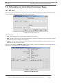
5.8 Scheduling and Controlling Provisioning Tasks - - - - - - - - - - - - - - - - - - - - - - - - - 5.8.1 One Time - - - - - - - - - - - - - - - - - - - - - - - - - - - - - - - - - - - - - - - - - - - - - - - - 5.8.2 Recurring - - - - - - - - - - - - - - - - - - - - - - - - - - - - - - - - - - - - - - - - - - - - - - - - 5.8.3 View Tasks Form - - - - - - - - - - - - - - - - - - - - - - - - - - - - - - - - - - - - - - - - - - - -
5-237
5-237
5-238
5-239
5.9 Other Device Control Tasks - - - - - - - - - - - - - - - - - - - - - - - - - - - - - - - - - - - - - - - 5.9.1 Alarms/Events - - - - - - - - - - - - - - - - - - - - - - - - - - - - - - - - - - - - - - - - - - - - - 5.9.2 Performance - - - - - - - - - - - - - - - - - - - - - - - - - - - - - - - - - - - - - - - - - - - - - - 5.9.3 File Comparison (Text Files) - - - - - - - - - - - - - - - - - - - - - - - - - - - - - - - - - - - 5.9.4 Discover Attached iMG/RGs - - - - - - - - - - - - - - - - - - - - - - - - - - - - - - - - - - - 5.9.5 Display Switch Forwarding Database (iMAP Systems) - - - - - - - - - - - - - - - - - 5.9.6 Telnet / SSH to a Device - - - - - - - - - - - - - - - - - - - - - - - - - - - - - - - - - - - - - - 5.9.7 Browse Device (Rapier Device Only) - - - - - - - - - - - - - - - - - - - - - - - - - - - - - 5.9.8 Rediscovery Device (When Required) - - - - - - - - - - - - - - - - - - - - - - - - - - - - - 5.9.9 Managed Object Properties - - - - - - - - - - - - - - - - - - - - - - - - - - - - - - - - - - - - 5.9.10 Manage/Unmanage - - - - - - - - - - - - - - - - - - - - - - - - - - - - - - - - - - - - - - - - - -
5-240
5-240
5-240
5-241
5-248
5-249
5-249
5-250
5-251
5-251
5-251
AlliedView NMS Administration Guide (Table of Contents)
TOC-5
5.9.11 Update Status - - - - - - - - - - - - - - - - - - - - - - - - - - - - - - - - - - - - - - - - - - - - - - 5-251
5.10 Manage CLI Users- - - - - - - - - - - - - - - - - - - - - - - - - - - - - - - - - - - - - - - - - - - - - - - 5-252
5.11 Customer Cutover - - - - - - - - - - - - - - - - - - - - - - - - - - - - - - - - - - - - - - - - - - - - - - - 5-252
5.11.1 Overview - - - - - - - - - - - - - - - - - - - - - - - - - - - - - - - - - - - - - - - - - - - - - - - - - 5-252
5.11.2 Cutover Scenarios/Restrictions- - - - - - - - - - - - - - - - - - - - - - - - - - - - - - - - - - - 5-252
5.11.3 Procedure Overview- - - - - - - - - - - - - - - - - - - - - - - - - - - - - - - - - - - - - - - - - - 5-253
5.11.4 Procedure Example - Transfer to different cardtype - - - - - - - - - - - - - - - - - - - - - 5-255
5.11.5 Procedure Example - Transfer of iMG to different Port - - - - - - - - - - - - - - - - - - 5-260
6 Configuring Network Services - - - - - - - - - - - - - - - - - - - - - 6-1
6.1 Overview - - - - - - - - - - - - - - - - - - - - - - - - - - - - - - - - - - - - - - - - - - - - - - - - - - - - - - - -6-1
6.1.1 HVLANs (iMAP 9000 Devices Only) - - - - - - - - - - - - - - - - - - - - - - - - - - - - - - - -6-2
6.1.2 VLAN Translations - - - - - - - - - - - - - - - - - - - - - - - - - - - - - - - - - - - - - - - - - - - - -6-4
6.1.3 Network VLANs - - - - - - - - - - - - - - - - - - - - - - - - - - - - - - - - - - - - - - - - - - - - - - -6-6
6.1.4 Profile Management- - - - - - - - - - - - - - - - - - - - - - - - - - - - - - - - - - - - - - - - - - - - -6-8
6.1.5 Quality of Service - - - - - - - - - - - - - - - - - - - - - - - - - - - - - - - - - - - - - - - - - - - - - -6-8
6.1.6 Protection Switching (EPSR) - - - - - - - - - - - - - - - - - - - - - - - - - - - - - - - - - - - - - -6-9
6.1.7 Circuit Emulation Service (CES) - - - - - - - - - - - - - - - - - - - - - - - - - - - - - - - - - - - -6-9
6.1.8 NTE8 Service - - - - - - - - - - - - - - - - - - - - - - - - - - - - - - - - - - - - - - - - - - - - - - - - -6-9
6.2 Topology Maps and Inventory Tables - - - - - - - - - - - - - - - - - - - - - - - - - - - - - - - - - - - -6-9
6.2.1 Overview - - - - - - - - - - - - - - - - - - - - - - - - - - - - - - - - - - - - - - - - - - - - - - - - - - - -6-9
6.2.2 VLAN Network Map (Layer 3) - - - - - - - - - - - - - - - - - - - - - - - - - - - - - - - - - - - - 6-10
6.2.3 VLAN Sub Maps (Layer 2)- - - - - - - - - - - - - - - - - - - - - - - - - - - - - - - - - - - - - - - 6-11
6.2.4 Physical Network Map - - - - - - - - - - - - - - - - - - - - - - - - - - - - - - - - - - - - - - - - - - 6-12
6.2.5 VLAN Interfaces Inventory Table - - - - - - - - - - - - - - - - - - - - - - - - - - - - - - - - - - 6-15
6.2.6 Physical Links Inventory Table - - - - - - - - - - - - - - - - - - - - - - - - - - - - - - - - - - - - 6-17
6.2.7 Alarm Indicators from the Maps and Inventory Tables - - - - - - - - - - - - - - - - - - - - 6-18
6.3 Creating Network VLANs - - - - - - - - - - - - - - - - - - - - - - - - - - - - - - - - - - - - - - - - - - - 6-18
6.3.1 Creating Initial VLAN Information - - - - - - - - - - - - - - - - - - - - - - - - - - - - - - - - - 6-18
6.3.2 Modify the Network VLAN Link Configuration- - - - - - - - - - - - - - - - - - - - - - - - - 6-19
6.3.3 Configure the VLAN Interfaces (Service Ports) - - - - - - - - - - - - - - - - - - - - - - - - - 6-21
6.4 Extending Network VLANs - - - - - - - - - - - - - - - - - - - - - - - - - - - - - - - - - - - - - - - - - - 6-24
6.5 Trimming or Splitting Network VLANs - - - - - - - - - - - - - - - - - - - - - - - - - - - - - - - - - 6-27
6.6 Deleting Network VLANs - - - - - - - - - - - - - - - - - - - - - - - - - - - - - - - - - - - - - - - - - - - 6-27
6.7 Network VLAN Manager (Excluding EPSR) - - - - - - - - - - - - - - - - - - - - - - - - - - - - - - 6-28
6.7.1 Overview - - - - - - - - - - - - - - - - - - - - - - - - - - - - - - - - - - - - - - - - - - - - - - - - - - - 6-28
6.7.2 Create Network VLAN- - - - - - - - - - - - - - - - - - - - - - - - - - - - - - - - - - - - - - - - - - 6-28
6.7.3 Using the Network VLAN Hierarchy - - - - - - - - - - - - - - - - - - - - - - - - - - - - - - - - 6-29
6.7.4 Using the Device VLAN Hierarchy - - - - - - - - - - - - - - - - - - - - - - - - - - - - - - - - - 6-30
6.7.5 Importing Physical Link Configurations - - - - - - - - - - - - - - - - - - - - - - - - - - - - - - 6-31
6.7.6 Exporting Physical Link Configurations - - - - - - - - - - - - - - - - - - - - - - - - - - - - - - 6-33
6.7.7 Viewing VLAN Outage Statistics- - - - - - - - - - - - - - - - - - - - - - - - - - - - - - - - - - - 6-34
6.8 Example of Creating Network VLANs - - - - - - - - - - - - - - - - - - - - - - - - - - - - - - - - - - 6-36
6.8.1 Sample Island-Based Network VLAN - - - - - - - - - - - - - - - - - - - - - - - - - - - - - - - 6-36
6.8.2 Extending the Island-Based VLAN - - - - - - - - - - - - - - - - - - - - - - - - - - - - - - - - - 6-42
6.9 Example Configurations for HVLAN, Translations - - - - - - - - - - - - - - - - - - - - - - - - - 6-45
TOC-6
AlliedView NMS Administration Guide (Table of Contents)
6.9.1 Overview - - - - - - - - - - - - - - - - - - - - - - - - - - - - - - - - - - - - - - - - - - - - - - - - - - 6-45
6.9.2 HVLAN Configuration - - - - - - - - - - - - - - - - - - - - - - - - - - - - - - - - - - - - - - - - - 6-45
6.9.3 VLAN Translations Configuration - - - - - - - - - - - - - - - - - - - - - - - - - - - - - - - - - 6-52
6.10 Profile Management - - - - - - - - - - - - - - - - - - - - - - - - - - - - - - - - - - - - - - - - - - - - - 6.10.1 Profile Configuration Parameters - Devices and Scoping - - - - - - - - - - - - - - - - 6.10.2 Creating a Profile - - - - - - - - - - - - - - - - - - - - - - - - - - - - - - - - - - - - - - - - - - - 6.10.3 Viewing and Modifying Profiles - - - - - - - - - - - - - - - - - - - - - - - - - - - - - - - - - 6.10.4 Deleting a Profile - - - - - - - - - - - - - - - - - - - - - - - - - - - - - - - - - - - - - - - - - - - 6.10.5 Deploying a Profile- - - - - - - - - - - - - - - - - - - - - - - - - - - - - - - - - - - - - - - - - - 6.10.6 Redeploying a Profile - - - - - - - - - - - - - - - - - - - - - - - - - - - - - - - - - - - - - - - - 6.10.7 Scheduling Deployment of a Profile - - - - - - - - - - - - - - - - - - - - - - - - - - - - - - 6.10.8 Deploying Changes to a Profile- - - - - - - - - - - - - - - - - - - - - - - - - - - - - - - - - - 6.10.9 Profile Monitoring - - - - - - - - - - - - - - - - - - - - - - - - - - - - - - - - - - - - - - - - - - 6.10.10 Keeping the Profile Parameters and Ports/Devices in Sync - - - - - - - - - - - - - - 6.10.11 Coordination of External and NMS Profiles - - - - - - - - - - - - - - - - - - - - - - - - 6.10.12 ADSL G.Bond Creation and use of Profiles- - - - - - - - - - - - - - - - - - - - - - - - - 6.10.13 Multiple VC Support on ADSL Port - - - - - - - - - - - - - - - - - - - - - - - - - - - - - 6.10.14 Multiple VC Support on SHDSL Port - - - - - - - - - - - - - - - - - - - - - - - - - - - - 6.10.15 Multiple VC Support on VDSL Port - - - - - - - - - - - - - - - - - - - - - - - - - - - - - 6.10.16 DS3 SFP Support - - - - - - - - - - - - - - - - - - - - - - - - - - - - - - - - - - - - - - - - - - 6.10.17 Changes for the Enterprise Edition- - - - - - - - - - - - - - - - - - - - - - - - - - - - - - - -
6-53
6-54
6-57
6-60
6-60
6-61
6-64
6-64
6-65
6-65
6-66
6-66
6-69
6-70
6-70
6-70
6-77
6-82
6.11 Quality of Service (QoS) Network Management - - - - - - - - - - - - - - - - - - - - - - - - - - 6-87
6.11.1 Overview - - - - - - - - - - - - - - - - - - - - - - - - - - - - - - - - - - - - - - - - - - - - - - - - - 6-87
6.11.2 QoS Flows- - - - - - - - - - - - - - - - - - - - - - - - - - - - - - - - - - - - - - - - - - - - - - - - - 6-93
6.11.3 QoS Priority Action - - - - - - - - - - - - - - - - - - - - - - - - - - - - - - - - - - - - - - - - - - 6-96
6.11.4 QoS Traffic Action Form - - - - - - - - - - - - - - - - - - - - - - - - - - - - - - - - - - - - - - - 6-99
6.11.5 QoS Policy Action Form - - - - - - - - - - - - - - - - - - - - - - - - - - - - - - - - - - - - - - 6-103
6.11.6 QoS Policy Maintenance Window (Defining a Policy) - - - - - - - - - - - - - - - - - - 6-104
6.11.7 QoS Policy Rule Form- - - - - - - - - - - - - - - - - - - - - - - - - - - - - - - - - - - - - - - - 6-107
6.11.8 Viewing Default Flows, Priorities, Actions, and Policies - - - - - - - - - - - - - - - - - 6-108
6.11.9 Example of an iMAP Device Class Policy - - - - - - - - - - - - - - - - - - - - - - - - - - 6-109
6.11.10 Example of a Rapier/SwitchBlade Policy - - - - - - - - - - - - - - - - - - - - - - - - - - -6-111
6.11.11 Example of an EPON/ONU Interface Policy - - - - - - - - - - - - - - - - - - - - - - - - 6-117
6.11.12 QoSPolicies for the FX20 Interface - - - - - - - - - - - - - - - - - - - - - - - - - - - - - - 6-122
6.12 Troubleshooting Policies and Profile Management - - - - - - - - - - - - - - - - - - - - - - 6.12.1 Overview (QoS Deployments Table) - - - - - - - - - - - - - - - - - - - - - - - - - - - - - 6.12.2 Determine which QoS Policy is Assigned to a Port - - - - - - - - - - - - - - - - - - - 6.12.3 Determine Whether a QoS Policy is Deployed and In-sync on a Device - - - - - 6.12.4 Determine whether a QoS Policy has the Desired Configuration - - - - - - - - - - 6.12.5 Redeploying Policies- - - - - - - - - - - - - - - - - - - - - - - - - - - - - - - - - - - - - - - - -
6-130
6-130
6-130
6-130
6-131
6-131
6.13 Protection Switching-EPSR - - - - - - - - - - - - - - - - - - - - - - - - - - - - - - - - - - - - - - - 6.13.1 Overview of EPSR Topology - - - - - - - - - - - - - - - - - - - - - - - - - - - - - - - - - - 6.13.2 The Network VLAN Manager Application - Configure Control Ring - - - - - - - 6.13.3 The Network VLAN Manager Application - Configure Data Ring - - - - - - - - - 6.13.4 Configuration Guidelines - - - - - - - - - - - - - - - - - - - - - - - - - - - - - - - - - - - - - 6.13.5 Example Scenario- - - - - - - - - - - - - - - - - - - - - - - - - - - - - - - - - - - - - - - - - - 6.13.6 Troubleshooting the EPSR Configuration - - - - - - - - - - - - - - - - - - - - - - - - - - 6.13.7 Status of Transit Nodes for AlliedWare Plus Devices - - - - - - - - - - - - - - - - - - -
6-134
6-134
6-136
6-142
6-144
6-145
6-154
6-160
AlliedView NMS Administration Guide (Table of Contents)
TOC-7
6.14 SuperLoop Prevention (Superring) - - - - - - - - - - - - - - - - - - - - - - - - - - - - - - - - - - - 6-161
6.14.1 Overview - - - - - - - - - - - - - - - - - - - - - - - - - - - - - - - - - - - - - - - - - - - - - - - - - 6-161
6.14.2 Creating the EPSR SuperRIng - - - - - - - - - - - - - - - - - - - - - - - - - - - - - - - - - - - 6-163
6.15 Customer Management - - - - - - - - - - - - - - - - - - - - - - - - - - - - - - - - - - - - - - - - - - - 6-179
6.15.1 Overview - - - - - - - - - - - - - - - - - - - - - - - - - - - - - - - - - - - - - - - - - - - - - - - - - 6-179
6.15.2 Add New Triple Play Customer - Four Examples - - - - - - - - - - - - - - - - - - - - - - 6-179
6.15.3 Add DS1/E1 Customer - - - - - - - - - - - - - - - - - - - - - - - - - - - - - - - - - - - - - - - - 6-184
6.15.4 View/Modify Customer Ports - - - - - - - - - - - - - - - - - - - - - - - - - - - - - - - - - - - 6-184
6.15.5 Deprovision Customer Ports - - - - - - - - - - - - - - - - - - - - - - - - - - - - - - - - - - - - 6-186
6.16 Circuit Emulation Service - - - - - - - - - - - - - - - - - - - - - - - - - - - - - - - - - - - - - - - - - 6-187
6.16.1 Overview (CES8 and iMG6x6MOD Configurations)- - - - - - - - - - - - - - - - - - - - 6-187
6.16.2 CES8 Configuration - Overview of Steps- - - - - - - - - - - - - - - - - - - - - - - - - - - - 6-188
6.16.3 Create/Provision CES8 card to Support DS1 Ports (Same Device) - - - - - - - - - - - 6-189
6.16.4 Create DS1 Profile (DS1 and P-SPAN) - - - - - - - - - - - - - - - - - - - - - - - - - - - - - 6-190
6.16.5 Provision the Two DS1 Ports - - - - - - - - - - - - - - - - - - - - - - - - - - - - - - - - - - - - 6-191
6.16.6 View Provisioning Results - - - - - - - - - - - - - - - - - - - - - - - - - - - - - - - - - - - - - 6-193
6.16.7 Provisioning iMG6x6MOD with T1/E1 Card and CES - - - - - - - - - - - - - - - - - - 6-200
6.17 NTE8 Dual Circuit Provisioning - - - - - - - - - - - - - - - - - - - - - - - - - - - - - - - - - - - - - 6-217
6.17.1 Main Provisioning Steps - - - - - - - - - - - - - - - - - - - - - - - - - - - - - - - - - - - - - - - 6-218
6.17.2 Create/Provision NTE8 cards to Support DS1 Ports (Different Devices) - - - - - - - 6-219
6.17.3 Create DS1 Profile - - - - - - - - - - - - - - - - - - - - - - - - - - - - - - - - - - - - - - - - - - - 6-219
6.17.4 Provisioning one NTE8 Circuit - - - - - - - - - - - - - - - - - - - - - - - - - - - - - - - - - - 6-221
6.17.5 Adding PPPs to the MLPPP - - - - - - - - - - - - - - - - - - - - - - - - - - - - - - - - - - - - 6-223
6.17.6 Viewing Provisioning Results - Port Inventory Table- - - - - - - - - - - - - - - - - - - - 6-225
6.17.7 Viewing Provisioning Results - Port Details Form- - - - - - - - - - - - - - - - - - - - - - 6-225
6.17.8 Viewing NTE8 Endpoints on Physical Map - - - - - - - - - - - - - - - - - - - - - - - - - - 6-233
6.17.9 Viewing NTE8 Configuration Faults- - - - - - - - - - - - - - - - - - - - - - - - - - - - - - - 6-234
6.18 Upstream Control Protocol (UCP) Display - - - - - - - - - - - - - - - - - - - - - - - - - - - - - 6-234
6.18.1 VLAN Submap Display - - - - - - - - - - - - - - - - - - - - - - - - - - - - - - - - - - - - - - - 6-235
6.18.2 Network Inventory Display - - - - - - - - - - - - - - - - - - - - - - - - - - - - - - - - - - - - - 6-235
6.18.3 Events View (Change of State)- - - - - - - - - - - - - - - - - - - - - - - - - - - - - - - - - - - 6-236
6.19 Link Discovery - - - - - - - - - - - - - - - - - - - - - - - - - - - - - - - - - - - - - - - - - - - - - - - - - 6-237
6.20 Software Upgrade with EPSR- - - - - - - - - - - - - - - - - - - - - - - - - - - - - - - - - - - - - - - 6-238
6.20.1 Overview - - - - - - - - - - - - - - - - - - - - - - - - - - - - - - - - - - - - - - - - - - - - - - - - - 6-238
6.20.2 Upgrading all Nodes for an EPSR Ring- - - - - - - - - - - - - - - - - - - - - - - - - - - - - 6-238
6.20.3 Upgrading One Node that is part of an EPSR Configuration - - - - - - - - - - - - - - - 6-242
6.20.4 Upgrading Devices when EPSR not Properly Configured- - - - - - - - - - - - - - - - - 6-244
6.21 Diagnostic Audit - - - - - - - - - - - - - - - - - - - - - - - - - - - - - - - - - - - - - - - - - - - - - - - - 6-245
6.21.1 Network VLANs - - - - - - - - - - - - - - - - - - - - - - - - - - - - - - - - - - - - - - - - - - - - 6-245
6.21.2 Audit the CES Circuit on the iMG6x6MOD or CES8 Card- - - - - - - - - - - - - - - - 6-248
6.22 Port Authentication (802.1x)- - - - - - - - - - - - - - - - - - - - - - - - - - - - - - - - - - - - - - - - 6-251
6.22.1 Port Authentication for a Device - - - - - - - - - - - - - - - - - - - - - - - - - - - - - - - - - 6-251
6.22.2 Profiles with Port Authentication - - - - - - - - - - - - - - - - - - - - - - - - - - - - - - - - - 6-254
6.22.3 Etherlike Port - - - - - - - - - - - - - - - - - - - - - - - - - - - - - - - - - - - - - - - - - - - - - - 6-255
TOC-8
AlliedView NMS Administration Guide (Table of Contents)
7 Provisioning the iMG/RG- - - - - - - - - - - - - - - - - - - - - - - - -7-1
7.1 Overview - - - - - - - - - - - - - - - - - - - - - - - - - - - - - - - - - - - - - - - - - - - - - - - - - - - - - - - - 7-1
7.1.1 Roadmap for this Section- - - - - - - - - - - - - - - - - - - - - - - - - - - - - - - - - - - - - - - - - 7-1
7.1.2 Feature List for Release 12 (up through SP1) - - - - - - - - - - - - - - - - - - - - - - - - - - - 7-1
7.2 Provisioning Strategy - - - - - - - - - - - - - - - - - - - - - - - - - - - - - - - - - - - - - - - - - - - - - - - 7-5
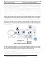
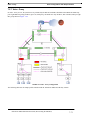
7.2.1 Main Concepts (Profiles, Triple Play Form, DHCP Discovery) - - - - - - - - - - - - - - - 7-5
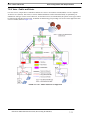
7.2.2 Deployment Models (Access Islands, Open Access, multi-service VLANs) - - - - - - 7-5
7.2.3 iMG/RG Types Supported - - - - - - - - - - - - - - - - - - - - - - - - - - - - - - - - - - - - - - - - 7-9
7.2.4 Provisioning Strategies - - - - - - - - - - - - - - - - - - - - - - - - - - - - - - - - - - - - - - - - - 7-10
7.2.5 Configuring Components for DHCP Discovery- - - - - - - - - - - - - - - - - - - - - - - - - 7-11
7.2.6 Naming Conventions to Identify Components (DNS) - - - - - - - - - - - - - - - - - - - - - 7-17
7.2.7 Naming Convention for Customer IDs (Triple Play Form) - - - - - - - - - - - - - - - - - 7-24
7.2.8 Changing Customer IDs - - - - - - - - - - - - - - - - - - - - - - - - - - - - - - - - - - - - - - - - 7-25
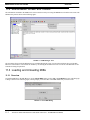
7.3 Viewing iMG/RG on the AlliedView NMS - - - - - - - - - - - - - - - - - - - - - - - - - - - - - - - 7-26
7.4 Creating RG Profiles with Field Descriptions - - - - - - - - - - - - - - - - - - - - - - - - - - - - 7.4.1 Overview - - - - - - - - - - - - - - - - - - - - - - - - - - - - - - - - - - - - - - - - - - - - - - - - - 7.4.2 General Profile- - - - - - - - - - - - - - - - - - - - - - - - - - - - - - - - - - - - - - - - - - - - - - 7.4.3 RG Internet Profile - - - - - - - - - - - - - - - - - - - - - - - - - - - - - - - - - - - - - - - - - - - 7.4.4 Video Profile - - - - - - - - - - - - - - - - - - - - - - - - - - - - - - - - - - - - - - - - - - - - - - - 7.4.5 Voice Port Profile - - - - - - - - - - - - - - - - - - - - - - - - - - - - - - - - - - - - - - - - - - - - 7.4.6 Business Group ID for SIP- - - - - - - - - - - - - - - - - - - - - - - - - - - - - - - - - - - - - - -
7-28
7-28
7-28
7-36
7-51
7-53
7-58
7.5 Basic Configurations with Sample Profiles - - - - - - - - - - - - - - - - - - - - - - - - - - - - - - 7.5.1 Overview - - - - - - - - - - - - - - - - - - - - - - - - - - - - - - - - - - - - - - - - - - - - - - - - - 7.5.2 Transparent LAN Service (TLS) - - - - - - - - - - - - - - - - - - - - - - - - - - - - - - - - - - 7.5.3 Internet - Bridged - - - - - - - - - - - - - - - - - - - - - - - - - - - - - - - - - - - - - - - - - - - - 7.5.4 Internet - Routed - - - - - - - - - - - - - - - - - - - - - - - - - - - - - - - - - - - - - - - - - - - - 7.5.5 Internet - Routed - NAT- - - - - - - - - - - - - - - - - - - - - - - - - - - - - - - - - - - - - - - - 7.5.6 Video - Snooping - - - - - - - - - - - - - - - - - - - - - - - - - - - - - - - - - - - - - - - - - - - - 7.5.7 Video - Proxy - - - - - - - - - - - - - - - - - - - - - - - - - - - - - - - - - - - - - - - - - - - - - - 7.5.8 Voice - Public and Private - - - - - - - - - - - - - - - - - - - - - - - - - - - - - - - - - - - - - - 7.5.9 ADSL iMG with multiple VCs - - - - - - - - - - - - - - - - - - - - - - - - - - - - - - - - - - - -
7-59
7-59
7-60
7-62
7-64
7-67
7-71
7-73
7-75
7-78
7.6 Datafilling the Triple Play Form - Examples- - - - - - - - - - - - - - - - - - - - - - - - - - - - - - 7-83
7.6.1 Overview - - - - - - - - - - - - - - - - - - - - - - - - - - - - - - - - - - - - - - - - - - - - - - - - - - 7-83
7.6.2 Configuration 1 Example - POTS, Derived Voice, Internet, Video, TLS - - - - - - - - 7-84
7.6.3 Configuration 2 - Multiple Video, Data, Derived Voice - - - - - - - - - - - - - - - - - - - 7-87
7.6.4 Configuration 3 - Static Provisioning (no DHCP) - - - - - - - - - - - - - - - - - - - - - - - 7-89
7.6.5 Configuration 4 - EPON/ONU Interface Connected with iMG646PX-ON - - - - - - - 7-98
7.6.6 Configuration 5 - Voice Service Provided by SIP- - - - - - - - - - - - - - - - - - - - - - - 7-102
7.6.7 Configuration 6 - Multi-Service VLAN - - - - - - - - - - - - - - - - - - - - - - - - - - - - - 7-104
7.6.8 Configuration 7 - iMG7x6MOD with HPNA - - - - - - - - - - - - - - - - - - - - - - - - - 7-108
7.6.9 Configuration 8 - AlliedWare Plus Device - - - - - - - - - - - - - - - - - - - - - - - - - - - 7-112
7.6.10 Configuration 9 - Microsoft© Mediaroom™ with the iMG/RG - - - - - - - - - - - - 7-114
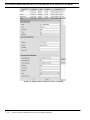
7.7 Provisioning the iMG/RG (Managed Object Properties) - - - - - - - - - - - - - - - - - - - 7.7.1 Overview - - - - - - - - - - - - - - - - - - - - - - - - - - - - - - - - - - - - - - - - - - - - - - - - 7.7.2 Managed Object Properties for the iMG/RG - - - - - - - - - - - - - - - - - - - - - - - - - 7.7.3 Creating Custom Views for an Access Island - - - - - - - - - - - - - - - - - - - - - - - - -
AlliedView NMS Administration Guide (Table of Contents)
7-121
7-121
7-121
7-125
TOC-9
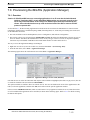
7.8 Provisioning the iMG/RG (Application Manager) - - - - - - - - - - - - - - - - - - - - - - - - - 7-133
7.8.1 Overview - - - - - - - - - - - - - - - - - - - - - - - - - - - - - - - - - - - - - - - - - - - - - - - - - - 7-133
7.8.2 Backup/Restore- - - - - - - - - - - - - - - - - - - - - - - - - - - - - - - - - - - - - - - - - - - - - - 7-134
7.8.3 Device Configuration - - - - - - - - - - - - - - - - - - - - - - - - - - - - - - - - - - - - - - - - - - 7-134
7.8.4 Software Configuration - - - - - - - - - - - - - - - - - - - - - - - - - - - - - - - - - - - - - - - - 7-134
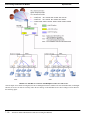
7.9 Provisioning Guidelines for Models - - - - - - - - - - - - - - - - - - - - - - - - - - - - - - - - - - - 7-135
7.9.1 Open Access- - - - - - - - - - - - - - - - - - - - - - - - - - - - - - - - - - - - - - - - - - - - - - - - 7-135
7.9.2 Multi-service VLANs - - - - - - - - - - - - - - - - - - - - - - - - - - - - - - - - - - - - - - - - - 7-138
7.9.3 iMG6x6MOD/iMG7x6MOD - Translation and HPNA Diagnostics - - - - - - - - - - - 7-139
7.9.4 iBG915-FX - - - - - - - - - - - - - - - - - - - - - - - - - - - - - - - - - - - - - - - - - - - - - - - - 7-143
7.9.5 iMG7x6MOD - - - - - - - - - - - - - - - - - - - - - - - - - - - - - - - - - - - - - - - - - - - - - - - 7-151
7.9.6 Split Management for Wireless iMG- - - - - - - - - - - - - - - - - - - - - - - - - - - - - - - - 7-157
7.9.7 Changing VoIP Endpoint Syntax - - - - - - - - - - - - - - - - - - - - - - - - - - - - - - - - - - 7-163
7.9.8 Provisioning Custom VLANs - - - - - - - - - - - - - - - - - - - - - - - - - - - - - - - - - - - - 7-164
7.9.9 Error Conditions when Provisioning- - - - - - - - - - - - - - - - - - - - - - - - - - - - - - - - 7-167
7.10 Installation Procedures - - - - - - - - - - - - - - - - - - - - - - - - - - - - - - - - - - - - - - - - - - - 7-168
7.10.1 Overview - - - - - - - - - - - - - - - - - - - - - - - - - - - - - - - - - - - - - - - - - - - - - - - - - 7-168
7.10.2 Installation Restrictions - - - - - - - - - - - - - - - - - - - - - - - - - - - - - - - - - - - - - - - 7-168
7.10.3 Pre-provision Future Customer (Provision iMAP Port, no Services)- - - - - - - - - - 7-169
7.10.4 Provision a new Customer (out of the box) - Triple Play - - - - - - - - - - - - - - - - - 7-173
7.10.5 Provisioning / De-Provisioning Voice Service - - - - - - - - - - - - - - - - - - - - - - - - 7-178
7.10.6 Provisioning / De-Provisioning Video Service - - - - - - - - - - - - - - - - - - - - - - - - 7-187
7.10.7 Change Quality of Existing Data Service - - - - - - - - - - - - - - - - - - - - - - - - - - - - 7-195
7.10.8 Reprovision Existing iMG/RG so incorporated into AlliedView NMS - - - - - - - - 7-196
7.10.9 De-Provision iMG/RG from AlliedView NMS - - - - - - - - - - - - - - - - - - - - - - - - 7-196
7.10.10 Changing a Customer ID - - - - - - - - - - - - - - - - - - - - - - - - - - - - - - - - - - - - - - 7-201
7.10.11 iMG/RG Recovery - - - - - - - - - - - - - - - - - - - - - - - - - - - - - - - - - - - - - - - - - - 7-202
7.10.12 Recover using new Hardware- - - - - - - - - - - - - - - - - - - - - - - - - - - - - - - - - - - 7-202
7.10.13 Configuring multi-service VLAN - - - - - - - - - - - - - - - - - - - - - - - - - - - - - - - - 7-203
7.11 Provisioning the iMG/RG (no iMAP or AW+) - - - - - - - - - - - - - - - - - - - - - - - - - - - 7-220
7.11.1 Overview - - - - - - - - - - - - - - - - - - - - - - - - - - - - - - - - - - - - - - - - - - - - - - - - - 7-220
7.11.2 DHCP Provisioning - - - - - - - - - - - - - - - - - - - - - - - - - - - - - - - - - - - - - - - - - - 7-220
7.11.3 GUI Provisioning- - - - - - - - - - - - - - - - - - - - - - - - - - - - - - - - - - - - - - - - - - - - 7-223
7.11.4 GUI Displays - - - - - - - - - - - - - - - - - - - - - - - - - - - - - - - - - - - - - - - - - - - - - - 7-225
7.12 Provisioning an iMG/RG with the LAN4 Feature - - - - - - - - - - - - - - - - - - - - - - - - - 7-226
7.12.1 Overview - - - - - - - - - - - - - - - - - - - - - - - - - - - - - - - - - - - - - - - - - - - - - - - - - 7-226
7.12.2 Profiles - - - - - - - - - - - - - - - - - - - - - - - - - - - - - - - - - - - - - - - - - - - - - - - - - - 7-226
7.12.3 Service Management GUI - - - - - - - - - - - - - - - - - - - - - - - - - - - - - - - - - - - - - - 7-227
7.12.4 Custom View - - - - - - - - - - - - - - - - - - - - - - - - - - - - - - - - - - - - - - - - - - - - - - 7-228
7.12.5 Procedure - Initial Installation of iMG with LAN4 - - - - - - - - - - - - - - - - - - - - - 7-232
7.12.6 Deprovision the iMG and Re-provision with the ADSL Uplink- - - - - - - - - - - - - 7-235
7.13 LCFO - - - - - - - - - - - - - - - - - - - - - - - - - - - - - - - - - - - - - - - - - - - - - - - - - - - - - - - - 7-237
7.14 iMG/RG Diagnostic Features - - - - - - - - - - - - - - - - - - - - - - - - - - - - - - - - - - - - - - - 7-239
7.14.1 iMG GR909 Diagnostics- - - - - - - - - - - - - - - - - - - - - - - - - - - - - - - - - - - - - - - 7-239
7.14.2 iMG LAN Diagnostics - - - - - - - - - - - - - - - - - - - - - - - - - - - - - - - - - - - - - - - - 7-241
7.15 System Power Management - - - - - - - - - - - - - - - - - - - - - - - - - - - - - - - - - - - - - - - - 7-244
7.15.1 System Power Management - - - - - - - - - - - - - - - - - - - - - - - - - - - - - - - - - - - - 7-244
7.15.2 LAN Ports Power Management - - - - - - - - - - - - - - - - - - - - - - - - - - - - - - - - - - 7-246
TOC-10
AlliedView NMS Administration Guide (Table of Contents)
7.15.3 LAN Ports State - - - - - - - - - - - - - - - - - - - - - - - - - - - - - - - - - - - - - - - - - - - - 7-247
7.15.4 TEL Ports Power Management - - - - - - - - - - - - - - - - - - - - - - - - - - - - - - - - - - 7-249
7.15.5 Voice Ports State- - - - - - - - - - - - - - - - - - - - - - - - - - - - - - - - - - - - - - - - - - - - 7-249
7.16 LAN Flow Control - - - - - - - - - - - - - - - - - - - - - - - - - - - - - - - - - - - - - - - - - - - - - - 7-250
7.17 Port-Based Rate Limiting - Reference - - - - - - - - - - - - - - - - - - - - - - - - - - - - - - - - 7-252
8 Setting Up Performance Management - - - - - - - - - - - - - - - -8-1
8.1 Overview - - - - - - - - - - - - - - - - - - - - - - - - - - - - - - - - - - - - - - - - - - - - - - - - - - - - - - - - 8-1
8.2 Data Collection Screen - - - - - - - - - - - - - - - - - - - - - - - - - - - - - - - - - - - - - - - - - - - - - - 8-2
8.2.1 Overview - - - - - - - - - - - - - - - - - - - - - - - - - - - - - - - - - - - - - - - - - - - - - - - - - - - 8-2
8.2.2 Screen Components for Statistics - - - - - - - - - - - - - - - - - - - - - - - - - - - - - - - - - - - 8-2
8.3 Data Collection - - - - - - - - - - - - - - - - - - - - - - - - - - - - - - - - - - - - - - - - - - - - - - - - - - 8.3.1 Overview - - - - - - - - - - - - - - - - - - - - - - - - - - - - - - - - - - - - - - - - - - - - - - - - - - 8.3.2 Polling Objects - - - - - - - - - - - - - - - - - - - - - - - - - - - - - - - - - - - - - - - - - - - - - - 8.3.3 Add a Statistic - - - - - - - - - - - - - - - - - - - - - - - - - - - - - - - - - - - - - - - - - - - - - - - 8.4 Threshold Notification - - - - - - - - - - - - - - - - - - - - - - - - - - - - - - - - - - - - - - - - - - - - 8.4.1 Overview - - - - - - - - - - - - - - - - - - - - - - - - - - - - - - - - - - - - - - - - - - - - - - - - - 8.4.2 Add Threshold - - - - - - - - - - - - - - - - - - - - - - - - - - - - - - - - - - - - - - - - - - - - - - 8.4.3 Associate Thresholds with Statistics - - - - - - - - - - - - - - - - - - - - - - - - - - - - - - - -
8-3
8-3
8-4
8-8
8-11
8-11
8-13
8-15
9 Setting Up Fault Management - - - - - - - - - - - - - - - - - - - - -9-1
9.1 Overview - - - - - - - - - - - - - - - - - - - - - - - - - - - - - - - - - - - - - - - - - - - - - - - - - - - - - - - - 9-1
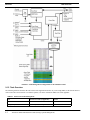
9.1.1 AlliedView NMS Fault Management Configuration- - - - - - - - - - - - - - - - - - - - - - - 9-1
9.1.2 Task Overview- - - - - - - - - - - - - - - - - - - - - - - - - - - - - - - - - - - - - - - - - - - - - - - - 9-2
9.2 Event View - - - - - - - - - - - - - - - - - - - - - - - - - - - - - - - - - - - - - - - - - - - - - - - - - - - - - - 9-3
9.3 Configuring Trap Parsers - - - - - - - - - - - - - - - - - - - - - - - - - - - - - - - - - - - - - - - - - - - 9.3.1 Using Trap Values in the PDU - - - - - - - - - - - - - - - - - - - - - - - - - - - - - - - - - - - - 9.3.2 Loading from a MIB - - - - - - - - - - - - - - - - - - - - - - - - - - - - - - - - - - - - - - - - - - - 9.3.3 Loading from a File - - - - - - - - - - - - - - - - - - - - - - - - - - - - - - - - - - - - - - - - - - - 9.3.4 Reordering the Trap Parser List - - - - - - - - - - - - - - - - - - - - - - - - - - - - - - - - - - - -
9-3
9-6
9-8
9-8
9-9
9.4 Configuring Event Parsers - - - - - - - - - - - - - - - - - - - - - - - - - - - - - - - - - - - - - - - - - - - 9-9
9.4.1 Overview - - - - - - - - - - - - - - - - - - - - - - - - - - - - - - - - - - - - - - - - - - - - - - - - - - - 9-9
9.4.2 Setting Event Parsers - - - - - - - - - - - - - - - - - - - - - - - - - - - - - - - - - - - - - - - - - - 9-10
9.4.3 Relationship Between User Properties and Custom Views- - - - - - - - - - - - - - - - - - 9-13
9.4.4 Setting up a SYSLOG Event to Create an Alarm - - - - - - - - - - - - - - - - - - - - - - - - 9-13
9.4.5 Changing Severity of Default Events (i.e. Status Update Failure) - - - - - - - - - - - - - 9-14
9.4.6 Changing Severity of Port-based Alarms - - - - - - - - - - - - - - - - - - - - - - - - - - - - - 9-19
9.5 Configuring Event Filters - - - - - - - - - - - - - - - - - - - - - - - - - - - - - - - - - - - - - - - - - - 9.5.1 Overview - - - - - - - - - - - - - - - - - - - - - - - - - - - - - - - - - - - - - - - - - - - - - - - - - 9.5.2 Setting Event Filters - - - - - - - - - - - - - - - - - - - - - - - - - - - - - - - - - - - - - - - - - - 9.5.3 Setting Event Filter Actions - - - - - - - - - - - - - - - - - - - - - - - - - - - - - - - - - - - - - 9.5.4 Example of Setting an Event Filter Action - - - - - - - - - - - - - - - - - - - - - - - - - - - 9.5.5 Setting Up Event Filters for SYSLOG Events - - - - - - - - - - - - - - - - - - - - - - - - - -
9-20
9-20
9-22
9-24
9-26
9-27
9.6 Configuring System Logs (NMS System Log Server)- - - - - - - - - - - - - - - - - - - - - - - - 9-27
AlliedView NMS Administration Guide (Table of Contents)
TOC-11
9.6.1
9.6.2
9.6.3
9.6.4
9.6.5
9.6.6
Configuring the System Log Server - - - - - - - - - - - - - - - - - - - - - - - - - - - - - - - - - 9-29
Applying Log Filters - - - - - - - - - - - - - - - - - - - - - - - - - - - - - - - - - - - - - - - - - - - 9-30
Configuring Log Actions - - - - - - - - - - - - - - - - - - - - - - - - - - - - - - - - - - - - - - - - 9-31
Viewing Logs - - - - - - - - - - - - - - - - - - - - - - - - - - - - - - - - - - - - - - - - - - - - - - - - 9-31
Disabling and Re-enabling Logs from a Device - - - - - - - - - - - - - - - - - - - - - - - - - 9-32
OTHER Event Type- - - - - - - - - - - - - - - - - - - - - - - - - - - - - - - - - - - - - - - - - - - - 9-32
9.7 Alarm View Display- - - - - - - - - - - - - - - - - - - - - - - - - - - - - - - - - - - - - - - - - - - - - - - - 9-32
9.8 Alarm Propagation - - - - - - - - - - - - - - - - - - - - - - - - - - - - - - - - - - - - - - - - - - - - - - - - 9-34
9.8.1 Overview - - - - - - - - - - - - - - - - - - - - - - - - - - - - - - - - - - - - - - - - - - - - - - - - - - - 9-34
9.8.2 Controlling Alarm Propagation - - - - - - - - - - - - - - - - - - - - - - - - - - - - - - - - - - - - 9-34
9.9 Configuring Alarm Filters - - - - - - - - - - - - - - - - - - - - - - - - - - - - - - - - - - - - - - - - - - - 9-35
9.9.1 Overview - - - - - - - - - - - - - - - - - - - - - - - - - - - - - - - - - - - - - - - - - - - - - - - - - - - 9-35
9.9.2 Example to Configure Alarm Filter and Actions - - - - - - - - - - - - - - - - - - - - - - - - - 9-36
9.10 Retrieval of Alarms during (Re)Discovery (Telesis MAP Devices Only) - - - - - - - - - -9-37
9.10.1 Overview - - - - - - - - - - - - - - - - - - - - - - - - - - - - - - - - - - - - - - - - - - - - - - - - - - 9-37
9.10.2 Enable / Disable the Feature (Feature is Optional)- - - - - - - - - - - - - - - - - - - - - - - 9-38
9.10.3 Restrictions / Limitations - - - - - - - - - - - - - - - - - - - - - - - - - - - - - - - - - - - - - - - 9-38
10 Using the HTML Interface - - - - - - - - - - - - - - - - - - - - - - 10-1
10.1 Overview - - - - - - - - - - - - - - - - - - - - - - - - - - - - - - - - - - - - - - - - - - - - - - - - - - - - - - 10-1
11 Built-in Browsers - SNMP MIB and CWMP - - - - - - - - - - 11-1
11.1 Overview - SNMP MIB - - - - - - - - - - - - - - - - - - - - - - - - - - - - - - - - - - - - - - - - - - - - 11-1
11.2 MIB Browser Screen and Toolbar - - - - - - - - - - - - - - - - - - - - - - - - - - - - - - - - - - - - - 11-2
11.3 Loading and Unloading MIBs - - - - - - - - - - - - - - - - - - - - - - - - - - - - - - - - - - - - - - - - 11-2
11.3.1 Overview - - - - - - - - - - - - - - - - - - - - - - - - - - - - - - - - - - - - - - - - - - - - - - - - - - 11-2
11.3.2 Loading Options (Directly, as Compiled Files, Using MySQL) - - - - - - - - - - - - - - 11-3
11.3.3 Loading MIBS as Compiled Files- - - - - - - - - - - - - - - - - - - - - - - - - - - - - - - - - - 11-4
11.3.4 Loading MIBs from a Database - - - - - - - - - - - - - - - - - - - - - - - - - - - - - - - - - - - 11-4
11.3.5 Loading MIBs Using MySQL - - - - - - - - - - - - - - - - - - - - - - - - - - - - - - - - - - - - 11-4
11.3.6 Unloading MIBs - - - - - - - - - - - - - - - - - - - - - - - - - - - - - - - - - - - - - - - - - - - - - 11-5
11.4 MIB Browser Settings - - - - - - - - - - - - - - - - - - - - - - - - - - - - - - - - - - - - - - - - - - - - - 11-5
11.5 SNMP Operations - - - - - - - - - - - - - - - - - - - - - - - - - - - - - - - - - - - - - - - - - - - - - - - - 11-5
11.5.1 Multi-Varbind Request - - - - - - - - - - - - - - - - - - - - - - - - - - - - - - - - - - - - - - - - - 11-6
11.6 MIB Browser – Table Operations - - - - - - - - - - - - - - - - - - - - - - - - - - - - - - - - - - - - - 11-6
11.7 Trap Viewer - - - - - - - - - - - - - - - - - - - - - - - - - - - - - - - - - - - - - - - - - - - - - - - - - - - - 11-8
11.8 Trap Parser - - - - - - - - - - - - - - - - - - - - - - - - - - - - - - - - - - - - - - - - - - - - - - - - - - - - 11-10
11.8.1 Overview - - - - - - - - - - - - - - - - - - - - - - - - - - - - - - - - - - - - - - - - - - - - - - - - - 11-10
11.8.2 Procedure to Create a Parser File - - - - - - - - - - - - - - - - - - - - - - - - - - - - - - - - - 11-11
11.8.3 Adding a Trap Definition from MIBs to a Parser File: - - - - - - - - - - - - - - - - - - - 11-12
11.8.4 Filtering Incoming Traps- - - - - - - - - - - - - - - - - - - - - - - - - - - - - - - - - - - - - - - 11-12
11.8.5 Setting Trap Parser Parameters- - - - - - - - - - - - - - - - - - - - - - - - - - - - - - - - - - - 11-12
11.9 Graphs - - - - - - - - - - - - - - - - - - - - - - - - - - - - - - - - - - - - - - - - - - - - - - - - - - - - - - - 11-13
TOC-12
AlliedView NMS Administration Guide (Table of Contents)
11.10 CWMP- - - - - - - - - - - - - - - - - - - - - - - - - - - - - - - - - - - - - - - - - - - - - - - - - - - - - - 11-15
12 Northbound Interface - - - - - - - - - - - - - - - - - - - - - - - - - 12-1
12.1 Overview - - - - - - - - - - - - - - - - - - - - - - - - - - - - - - - - - - - - - - - - - - - - - - - - - - - - - - 12-1
12.2 SOAP Implementation - - - - - - - - - - - - - - - - - - - - - - - - - - - - - - - - - - - - - - - - - - - 12.2.1 Overview (Apache Axis) - - - - - - - - - - - - - - - - - - - - - - - - - - - - - - - - - - - - - - 12.2.2 WSDL - - - - - - - - - - - - - - - - - - - - - - - - - - - - - - - - - - - - - - - - - - - - - - - - - - 12.2.3 Web Services - - - - - - - - - - - - - - - - - - - - - - - - - - - - - - - - - - - - - - - - - - - - - - -
12-2
12-2
12-3
12-3
12.3 User Interaction - - - - - - - - - - - - - - - - - - - - - - - - - - - - - - - - - - - - - - - - - - - - - - - - 12.3.1 Web Services Activation - - - - - - - - - - - - - - - - - - - - - - - - - - - - - - - - - - - - - - 12.3.2 User Security - - - - - - - - - - - - - - - - - - - - - - - - - - - - - - - - - - - - - - - - - - - - - - 12.3.3 Operation Threshold Activation - - - - - - - - - - - - - - - - - - - - - - - - - - - - - - - - - 12.3.4 Axis/SOAP Interface Client Development - Examples - - - - - - - - - - - - - - - - - - 12.3.5 Available Operations - - - - - - - - - - - - - - - - - - - - - - - - - - - - - - - - - - - - - - - - - 12.3.6 Provision Parameters- - - - - - - - - - - - - - - - - - - - - - - - - - - - - - - - - - - - - - - - - -
12-4
12-4
12-5
12-5
12-5
12-6
12-9
13 Appendices - - - - - - - - - - - - - - - - - - - - - - - - - - - - - - - - 13-1
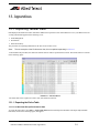
13.1 Exporting Tabular Data - - - - - - - - - - - - - - - - - - - - - - - - - - - - - - - - - - - - - - - - - - 13.1.1 Exporting the Entire Table - - - - - - - - - - - - - - - - - - - - - - - - - - - - - - - - - - - - - 13.1.2 Exporting Selected Items - - - - - - - - - - - - - - - - - - - - - - - - - - - - - - - - - - - - - - 13.1.3 Viewing a Data Export File - - - - - - - - - - - - - - - - - - - - - - - - - - - - - - - - - - - - 13.1.4 Viewing Data on a Web Browser- - - - - - - - - - - - - - - - - - - - - - - - - - - - - - - - - -
13-1
13-1
13-5
13-6
13-7
13.2 dhcpd Files - - - - - - - - - - - - - - - - - - - - - - - - - - - - - - - - - - - - - - - - - - - - - - - - - - - - 13-9
13.2.1 dhcpd.conf- - - - - - - - - - - - - - - - - - - - - - - - - - - - - - - - - - - - - - - - - - - - - - - - 13-10
13.2.2 dhcpd Includes - - - - - - - - - - - - - - - - - - - - - - - - - - - - - - - - - - - - - - - - - - - - - 13-10
13.2.3 DNS Configuration File- - - - - - - - - - - - - - - - - - - - - - - - - - - - - - - - - - - - - - - 13-18
AlliedView NMS Administration Guide (Table of Contents)
TOC-13
TOC-14
AlliedView NMS Administration Guide (Table of Contents)
1. Product Overview
1.1 Intended Audience for this Guide
This document is for those who are responsible for all aspects of configuring and administrating the network or networks they
manage. After reading this document, the user should be able to control all aspects of the AlliedView NMS and be able to
instruct all users on tasks they may perform and the impact of any changes they have made.
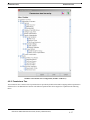
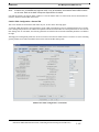
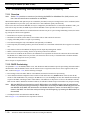
1.2 How this Document is Organized
The document covers all areas of administration that are controlled through the AlliedView NMS Application interface and
should be performed by the Administrator, such as:
•
•
•
•
•
•
•
•
Discovery (filters and configurator)
Topology
Maps
Security Management
Configuration Management
Fault Management
Performance Management
MIB Management
AlliedView NMS Administration Guide (Product Overview)
1-1
Reason for Update
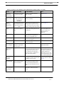
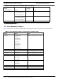
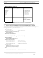
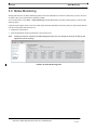
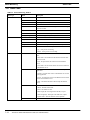
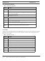
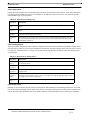
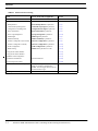
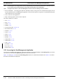
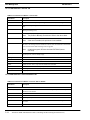
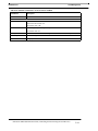
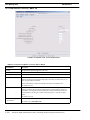
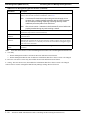
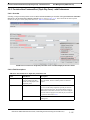
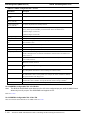
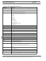
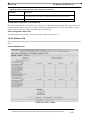
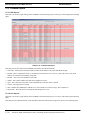
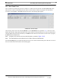
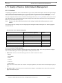
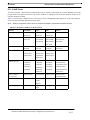
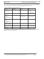
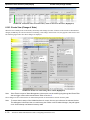
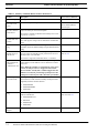
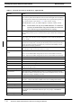
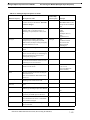
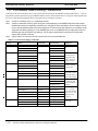
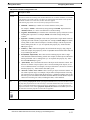
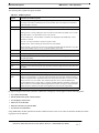
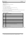
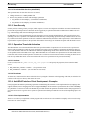
1.3 Reason for Update
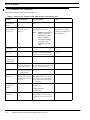
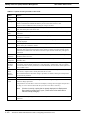
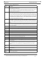
The following tables list the updates for Release 12.x.
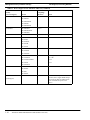
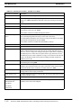
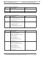
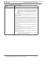
TABLE 1-1
Changes to the AlliedView NMS Administration Guide in Release 12.0
Feature
11.0 Functionality
12.0 Functionality
Notes
Release of Enterprise Edition
NMS
Not Available
The Enterprise Edition is newly introduced
Refer to 1.5.
NMS support for
iMAP products in
release 14.0
Support for iMAP 12.0
and releases back to
iMAP 9.0
iMAP 11.0, 12.0 and 14.0 are supported release for NMS 12.0.
The AlliedView NMS
will continue to support
7000 series products frozen at iMAP 6.1
Note:
Releases previous to
iMAP 11.0 are not
supported. If users
have a release
previous to release
11.0, they must
upgrade to at least
11.0.
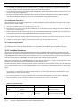
NMS Support for
iMAP 9810
Not Supported
The 9810 is fully supported.
Refer to 1.7.2.
NMS Support for
SBx 3112
Not Supported
The SBx 3112 is fully supported,
including product-specific features
such as Power over Ethernet (POE)
Refer to 1.7.2, 5.5.25., and
5.6.16.10.
NMS support for
Not Supported
These are fully supported
Refer to 1.7.2.
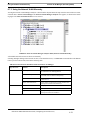
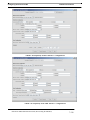
Network Services -> Profile presented all profiles
as a single item list
Network Services -> Profile presents a
list of Profile groupings, from which a
specific Profile can be chosen.
Refer to 6.10.2.
Included tabs for the
devices that supported
Etherlike ports
Product types are under one tab, Product Type.
Refer to 6.10.2.
iMG GR909
Diagnostics
Feature added to the
diagnostics tab in the port
details window for POTS
type ports
For the iMG6x6MOD and
iMG7x6MOD with at least release 37.4, voice lines can be enabled/disabled, and internal/external diagnostics can be run.
Refer to 7.14.1
NMS Support for
AT-8000 GS
Family
Not Supported
Fully Supported:
ATx900-48FS
ATx900-48FE
Profile GUI
Ethernet Profile
GUI
AT-8000GS/24
AT-8000GS/24POE
AT-8000GS/48
iMG/RG LAN
Diagnostics
1-2
Not Available
For the iMG6x6MOD and
iMG7x6MOD with at least release 37, diagnostics on LAN ports can be
run.
AlliedView NMS Administration Guide (Product Overview)
Refer to.7.14.2
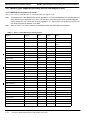
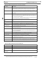
Reason for Update
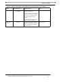
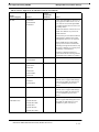
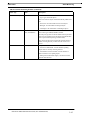
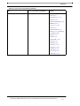
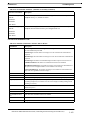
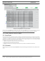
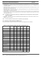
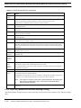
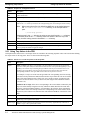
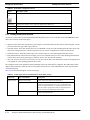
TABLE 1-1
Changes to the AlliedView NMS Administration Guide in Release 12.0 (Continued)
Feature
11.0 Functionality
12.0 Functionality
Notes
EPSR+
EPSR was supported and
provisionable
Support for EPSR+ with iMAP nodes
at release 14.0 and above
Refer to 6.13.2.
Network connectivity can be restored
when one or more links in a multiplelink failure occur, and there is still at
least one link that has not been
restored.
If all nodes support EPSR+, NMS by
default sets EPSR+ as enabled.
Restore files to
Devices
Supported
To make restore options more clear,
the forms for restore files are modified
to show only the options available for
the types of devices.
AlliedView NMS Administration Guide (Product Overview)
Refer to 5.3.2.3.
1-3
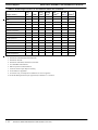
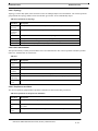
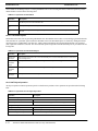
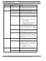
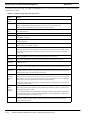
Reason for Update
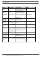
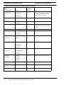
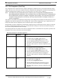
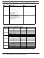
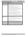
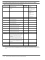
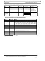
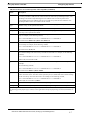
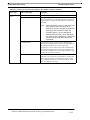
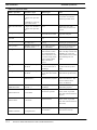
TABLE 1-2
Changes to the AlliedView NMS Administration Guide in Release 12.1(SP1)
Feature
12.0 Functionality
Client Inactivity
Logout
Not Supported
12.1 Functionality
Notes
The NMS tracks how long each client
session is open and will close the session when the timer expires.
Refer to 4.2 and 4.3.3.
Support of iMG/
RG with 3-8
release
The NMS supported 3-7
devices.
The NMS will support all of the iMG/
RGs that are available with the 3-8
release.
Refer to Table 7-2.
MPEG Testing
Supported on a subset of
iMG/RG devices
With release 3-8, all iMG/RGs support
MPEG testing. The NMS supports this
feature, and retains the same functionality for MPEG testing for previous
iMG/RG releases.
Refer to Table 7-2.
System Power
Management on
3-8 iMG/RGs
3-7 devices did not have
this feature, so not available
This feature helps to extend the battery
life during power loss.
Refer to Table 7-2.
FAX/Modem
Detection
(Enhanced)
3-7 devices had only two
options, and no NMS
support
All options, including Enhanced, supported
Refer to Table 7-2.
Setting Call
Waiting Activate/
Deactivate Prefix
(SIP)
This feature was in 3-7
devices, but no NMS support
Supported
Refer to Table 7-2.
Wireless
Upstream Rate
Limiting
Supported rate limiting
(CPU based) with rules
created for data VLANs
and configured on Local
and Internet VLANs
For wireless devices in 3-8, the iMG
allows configuring upstream rate limits, with the same rate limit values as
for wired ports.
Refer to Table 7-2.
Support of 40km
Optics Module
for iMGxx6MOD
Not available, so not supported
Available and Supported, with no
change in GUIs.
Refer to Table 7-2.
Flow Control for
iMG/RG LAN
ports
Not Available
Available and supported for iMG/
RG port GUIs.
Refer to Table 7-2.
Provisioning of
iMG/RG with
AlliedWare Plus
Devices
Can provision an iMG
only once it has come
into service.
Can provision the iMG the same way
as with iMAP ports (all components
provisionable, pre-provisioning so that
iMG/RG comes into service automatically when connected and powered on.
Refer to 7.6.9.
1-4
AlliedView NMS Administration Guide (Product Overview)
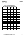
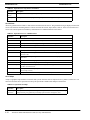
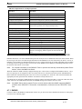
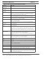
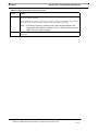
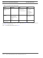
Reason for Update
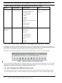
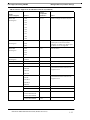
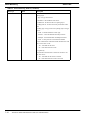
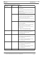
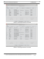
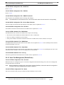
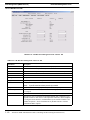
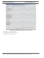
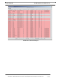
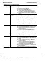
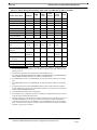
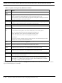
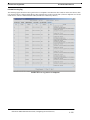
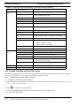
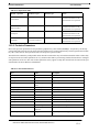
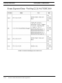
TABLE 1-3
Changes to the AlliedView NMS Administration Guide in Release 12.2(SP2)
Feature
12.1 Functionality
12.2 Functionality
Notes
Support for
Allied Telesis
iMAP software
Supported 14.0 (including the 9810 shelf)
Supports 15.0 interface cards for
iMAP (GE24BX)
Refer to 5.5.27.
Support for
SBx3112 software
Supported 14.2 shelf
cards (including the
GE24POE and
GE24SFP)
Supports 15.0 interface cards for
SBx3112 (GE24RJ)
Refer to 5.5.27.
Support
Microsoft©
Mediaroom™
The iMG release 3.8 supported Media Room configuration and all three
models
NMS supports one model for provisioning, separate upstream VLANs
(one VLAN for each service), which is
similar to existing Triple Play models.
Refer to Table 7-2.
Tabs for various
forms
Many forms had no tabs,
since only one application
When appropriate, panels have at least
one tab so that other applications can
be added later.
This mainly affects Profiles,
such as the iMAP Device
Profile (to support Port
Authentication for
SBx3112).
Port Authentication
Not supported
802.1X functions with Single Host are
supported. Devices supported are
SBx3112 and AlliedWare Plus.
Refer to 6.22.
SNMPv3 support
SNMPv2
With SNMPv3, messages to/from
devices are encrypted.
Refer to 3.2.3.
SSH
Telnet
With SSH, communication to/from
device is encrypted.
Refer to 3.2.4.
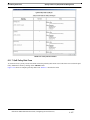
NMS support for
device categories
Refer to NMS 12.1
AlliedView NMS Administration Guide
Refer to 1.7
Families added include AT8100S and AT-9000.
Upgrade of
iMAP (CFC
load)
Supported
All CFC cards have loads for the GX
type, which replaces the GP. The load
that supports the GP and GX CFC
types (called the universal load) is
much larger. Refer to Allied Telesis
iMAP series documentation.
By default, the NMS loads
the universal load unless the
user builds a custom load or
manually modifies the
iMAP.xml file. Ensure you
have enough memory on the
CFC card for software files.
Provisioning
iMG with
GE24BX
Not Available
With the GE24BX, the iMG7x6MOD
(1G interface) is fully supported, with
GE24BX port set to AUTO.
For non-1G iMGs, the port
(profile) must be set. Refer
to 7.9.5.
Provisioning
VLANs on IMG
NMS supports creating
service VLANs when a
service is selected.
The iMG supports up to 16 VLANS.
Allows the user to specify custom
VLANs in General profile and the
NMS creates the specified VLANs in
iMGs.
Refer to 7.9.8.
Retain bootstrap
VLAN when provisioning the
iMG
Not available
The RG_General profile has a Persist
checkmark to retain the bootstrap
VLAN
Refer to Table 7-6.
AlliedView NMS Administration Guide (Product Overview)
1-5
The AlliedView Network Management System (NMS)User Privileges at the NMS and Product Level
TABLE 1-3
Changes to the AlliedView NMS Administration Guide in Release 12.2(SP2)
Feature
12.1 Functionality
12.2 Functionality
Notes
New Device Support (General)
Refer to NMS 12.1
Administration Guide
Support is added for the following:
Refer to Table 1-5 (x600),
Table 1-9 (AT-9000), and
Table 1-7.
x600 Family (AlliedWare Plus):
- ATx600-24Ts-POE+
The AT-9000 Family:
- 9000/28
- 9000/28SP
- 9000/52
The Allied Telesis Gateway Product
Family:
- iMG726-BD-ON
- iMG606-BD-R2
- iMG616-BD-R2
New Device Support (Specific
markets)
Not Applicable
These devices are for specific markets
and include:
Refer to Table 1-10.
Extreme devices:
- BD 8810
- Summit X250e-24t
- Summit X450a-24t
- Summit X450a-48t
Juniper
Netscreen
CentreCom
1.4 The AlliedView Network Management System (NMS)
For managing a network, the AlliedView NMS product provides a powerful client that presents the network and its devices in a
user-friendly way, allowing its users to learn quickly how the network is configured, how to reconfigure elements when necessary, and how to spot problems (or potential problems) before they degrade network performance.
The version of the AlliedView NMS release is shown in the main menu window, as shown in the following figure.
FIGURE 1-1
AlliedView NMS 12.0 GUI (for the SE Version)
To set up the AlliedView NMS product, the Administrator must first set up the AlliedView NMS product on a server configuration. Once the AlliedView NMS software is installed, the Administrator can query and control all aspects of the network by
changing the file configuration on the server or making changes using a client.
1.4.1 User Privileges at the NMS and Product Level
At the AlliedView NMS, groups are created and assigned actions that can be performed at the AlliedView NMS. Moreover,
users can be assigned to a group. so that they inherit the privileges of that group. Users can also be defined outside a group.
1-6
AlliedView NMS Administration Guide (Product Overview)
Compatibility of NMS and Device Loads
The AlliedView Network Management System (NMS)
Caution: At the device, there is a user name and password used to access the device, and this name/
password is used by all NMS users when accessing a device. To enable NMS users to query and
control a device, the device name and password must be at a security officer level. Failure to do
so may make certain operations performed at the NMS on a device to fail.
1.4.2 Compatibility of NMS and Device Loads
All of the tables in this Section about device support always assume that the NMS 12.0 load is being used. This is to ensure
that the NMS can support the latest version of a device.
Caution: Always ensure that you have the latest NMS load (12.0). If you upgrade a device to the loads
listed in Table 1-5 and are not running NMS 12.0, the NMS may not be able to manage the device.
1.4.3 Setting Web Browser Caching
The web browser caching function should be set to always check for updates from the server before retrieving content from
cache. Refer to the AlliedView NMS User Guide for details.
1.4.4 Using Default Prompt for Device Account Used by AlliedView NMS
Caution: One feature for AT and iMAP devices is the ability to change their default prompts to a custom
string. For AT devices, the default prompt ends with “>” and is required, and therefore should
not be changed/eliminated. For iMAP devices, there are no restrictions.
AlliedView NMS Administration Guide (Product Overview)
1-7
Levels of Support (Enterprise Edition)
Using Default Prompt for Device Account Used by Allied-
1.5 Levels of Support (Enterprise Edition)
The Enterprise Edition is introduced primarily for the smaller enterprise customer managing a network of less than 100
devices. All features of the Service Provider Edition (SE) are supported in the Enterprise Edition with the exception of customer provisioning of voice, video, and data services. Upgrade to the Service Provider Edition will be available in a future
release.
The following table summarizes the main aspects of the Enterprise Edition version of NMS, with references to additional information.
TABLE 1-4
Enterprise Edition Feature Set
Feature
Description when used in Enterprise Edition
Reference
Licensing process
The licensing process remains the same, with the customer receiving a
license file and using the License Manager GUI to apply the license.
AlliedView
NMS Installation Guide,
Appendix B.
On a running system, the License Keys option for the Status Monitoring
Tool shows that the license is Service Provider or Enterprise Edition.
Show current license once
installed
The License Keys option for the Status Monitoring Tool shows that the
license is Service Provider or Enterprise Edition.
Refer to 3.9.
The title bar or the NMS GUI includes the text Service Provider or Enterprise Edition
Platforms Supported
Windows 2003/2008 Server, Windows XP, Windows 7
Discovery Configurator
A separate Discovery Configurator Interface is used, with changes to the
GUI that match the Enterprise Edition discovery features.
Refer to 3.3
Devices Supported
These are the same as with the Service Provider Edition, as well as monitoring of non_ATI devices.
Refer to 1.7
Triple Play Customer
Management
Triple Play provisioning of voice, video, and data services are not supported by the Enterprise Edition NMS. Therefore, changes to the GUI that
reflect the Enterprise Edition feature set are:
Refer to
6.10.17.
- Under the Tools menu, Customer Management option is not available.
- In the Ports table, right click on ports does not include Provision New
Customer Port.
- Right click on iMG/RG from list does not include:
- Provision New Customer iMG/RG
- Deprovision Customer iMG/RG
- MPEG Test
- In Port Management window, buttons do not allow provision / deprovision of customer port.
- For Network Services -> Profiles, CPE Customer Profiles is removed.
1-8
AlliedView NMS Administration Guide (Product Overview)
Full Support, Excluding iMG/RG
.Managed Devices (Firmware Interop)
1.6 .Managed Devices (Firmware Interop)
1.6.1 Full Support, Excluding iMG/RG
Table 1-5 lists the devices that the AlliedView NMS 12.0 supports. More details about the support features for specific products is included in subsequent tables, since there may not be full support for all features.
Note:
Because of the Firmware Decoupling feature, there is no need for a column “Upgradeable Firmware
(Patch)”. The user obtains these files separately, and the Software Configuration selects which files are
compatible and which files can be deleted. Refer to 5.3.9.
.
TABLE 1-5
Device Support for the AlliedView NMS 12.2
Family
(Level of Support)
AT-AR200
Devices
Latest
Compatible
Firmware1
Notes
AT-AR250E
1.0.6
Use AT Loader for upgrade
(For AT Loader, contact your Allied
Telesis representative or go to the ATI
website.)
AT-AR410
AT-AR410
2.7.1-*
NMS 12.0 End-of-Life (EOL)
AT-AR415
AT-AR415S
2.9.1
NMS 12.0 End-of-Life (EOL)
AT-AR440
AT-AR440S
2.9.1-*
NMS 12.0 End-of-Life (EOL)
AT-AR442
AT-AR442S
2.9.1
NMS 12.0 End-of-Life (EOL)
AT-AR700
AT-AR720
2.6.*-*
NMS 12.0 End-of-Life (EOL)
2.9.1-*
NMS 12.0 End-of-Life (EOL)
AT-AR750S
2.9.1-*
NMS 12.0 End-of-Life (EOL)
AT-AR770S
2.9.1-*
NMS 12.0 End-of-Life (EOL)
AT-8012M
3.3.*
NMS 12.0 Support End-of-Life (EOL)
AT-AR740
AT-AR740DC
AT-AR725
AT-AR725DC
AT-AR745
AT-AR745DC
AT-8000
AT-8012MQS
AT-8016FMT
AT-8016FSC
AT-8016FST
AT-8024
AT-8024GB
AT-8024M
AT-8026FC
AT-8026T
AT-8088MT
AT-8088SC
AlliedView NMS Administration Guide (Product Overview)
1-9
.Managed Devices (Firmware Interop)
TABLE 1-5
Full Support, Excluding iMG/RG
Device Support for the AlliedView NMS 12.2 (Continued)
Family
(Level of Support)
Devices
Latest
Compatible
Firmware1
AT-8000S
AT-8000S16
3.0.0.*
Notes
AT-8000S24
AT-8000S24POE
AT-8000S48
AT-8000S48POE
AT-8000GS
AT-8000GS24
2.0.0.*
AT-8000GS24POE
AT-8000GS48
AT-8300
AT-8324
2.0.*
NMS 12.0 End-of-Life (EOL)
AT-8500
AT-8516FSC
1.4.*
NMS 12.0 End-of-Life (EOL)
AT-8524M
AT-8524POE
AT-8550GB
AT-8550SP
AT-8600
AT-8624POE
2.9.1-20
AT-8624T2M
AT-8648T2SP
AT-8700
AT-8724XL
2.9.1-20
Not supported:
AT-8724XLDC
2.6.1-04+
AT-8724XLDCNEBS
2.6.2
AT-8748XL
2.6.3
AT-8748XLDC
AT-8800
AT-8824
2.9.1-20
NMS 12.0 End-of-Life (EOL)
2.9.1-20
If an <AT-8900> is part of an EPSR
Domain, then to support EPSR management from the NMS, the NMS must be
set as an SNMPv2 trap host on the
device.
AT-8824DC
AT-8848
AT-8848DC
AT-8900
AT-8948
(Full Support)
1-10
AlliedView NMS Administration Guide (Product Overview)
Full Support, Excluding iMG/RG
TABLE 1-5
.Managed Devices (Firmware Interop)
Device Support for the AlliedView NMS 12.2 (Continued)
Family
(Level of Support)
Devices
Latest
Compatible
Firmware1
AT-9000
AT-9000/28
2.1.2
AT-9000/28SP
AT-9000/52
Notes
LLDP and LLDP-MED for this device is
not supported in NMS release 12.2; values cannot be retrieved through SNMP
(available lldp mibs does not return corresponding values).
Mode LED indicator is fixed in the ACT
Mode. The NMS has no provision for
Mode Selection.
Provision/De-provision button under Port
Management is disabled since Profile
Management function is not supported.
When SNMP function under SNMP
Agent provision menu is enabled after
disabling it through that same menu, only
the public community is restored; private
community is deleted/erased.
Software Configuration function is
removed from the Provisioning menu for
AT-9000 devices in NMS 12.2.1 release.
AT-9700
AT-9724TS
3.03
AT-9748TSXP
AT-9800
AT9812T
2.9.1-20
AT9812TDC
AT9812TF
AT9816GB
AT9816GBDC
AT9816GF
AT-9900
AT-9924SP
2.9.1-20
If an <AT-9900> is part of an EPSR
Domain, then to support EPSR management from the NMS, the NMS must be
set as an SNMPv2 trap host on the
device.
AT-9924T
AT-9924T4SP
AT-9900s
AT-9924Ts
3.2.1-03
If an <AT-9900s> is part of an EPSR
Domain, then to support EPSR management from the NMS, the NMS must be
set as an SNMPv2 trap host on the
device.
x600
ATx600-24Ts
5.3.4
(AlliedWare Plus)
ATx600-24TsXP
If an x600 is part of an EPSR Domain,
then to support EPSR management from
the NMS, the NMS must be set as an
SNMPv2 trap host on the device.
ATx600-24Ts-POE
ATx600-48Ts
ATx600-48TsXP
ATx600-24Ts-POE+
AlliedView NMS Administration Guide (Product Overview)
1-11
.Managed Devices (Firmware Interop)
TABLE 1-5
Full Support, Excluding iMG/RG
Device Support for the AlliedView NMS 12.2 (Continued)
Family
(Level of Support)
Devices
Latest
Compatible
Firmware1
x900
x900-12XTS
5.3.4
(AlliedWare Plus)
ATx900-24XS
ATx900-24XT
Notes
If an x900 is part of an EPSR Domain,
then to support EPSR management from
the NMS, the NMS must be set as an
SNMPv2 trap host on the device.
ATx900-24XT-N
x900
900-24XS
AlliedWare
900-24XT
x900 - 48
x900-48FE
3.2.1-03
2.9.1.20
x900-48FS
GenBand
GB-G6
GenBand
RG213
10-4-4
8-1-11
Supported for provisioning of MGCP
voice lines and configuration backup and
restore.
GB-G2
1.2.0
Functionally the same as the G6
RG213-H323
6.*
NMS 12.0 End-of-Life (EOL)
NMS 12.0 End-of-Life (EOL)
RG213-MGCP
RG213-SIP
Rapier
Rapier24
2.3.1-*
(Full Support)
Rapier48
2.7.0-*
Rapier “G”
RapierG6
2.7.3-09
NMS 12.0 End-of-Life (EOL)
2.9.1-20
NMS 12.0 Support End-of-Life (EOL)
2.7.5-09
NMS 12.0 Support End-of-Life (EOL)
RapierG6flx
RapierG6fmt
RapierG6fsx
Rapier “i”
Rapier24i
(Full Support)
Rapier24iDCNEBS
Rapier48i
Rapier 48W
SwitchBlade
SB4104AC
(AlliedWare)
SB4104DC
SB4108AC
SB4108DC
SwitchBlade
AT-SBx908
5.3.4
SBx3112
15.0.
T1000
1.3.*
(AlliedWare Plus)
SwitchBlade
(iMAP)
Telesis T1000
1.6.*
1-12
AlliedView NMS Administration Guide (Product Overview)
NMS 12.0 Support End-of-Life (EOL)
Full Support, Excluding iMG/RG
TABLE 1-5
.Managed Devices (Firmware Interop)
Device Support for the AlliedView NMS 12.2 (Continued)
Family
(Level of Support)
Devices
Latest
Compatible
Firmware1
iMAP 7000
7100
6.1.12
NMS 12.0 Support End-of-Life (EOL)
(Full Support)
7101
15.0
iMAP releases are supported up to two
releases prior to the current release.
Therefore, in release 12.0, releases prior
to iMAP 11.0 are not supported.
15.0
See note above.
15.0
See note above.
NMS 12.0 Support End-of-Life (EOL
Notes
7102
7103
7104
7105
7112
7115
7400
7700
iMAP 9000
9400
(Full Support)
9700
9810
iMAP 9000
9100
(Full Support)
9101
9102
9103
iMAP 9000
9400-56
(Full Support)
9700-56
DTM
NM1000
-
MC2700
CentreCOM-MC2700
1.2.*
CentreCom AR Series
AR415S
2.9.2-00
LLDP configuration per port is not supported and will return a ‘Function not
supported’ error.
2.7.9-*
LLDP configuration per port is not supported and will return a ‘Function not
supported’ error.
AR550S
AR560S
AR570S
CentreCom 8000 Series
8316XL
8324XL
8316XLR
8324XLR
8424TX
CentreCom 9400 Series
FS Series
CentreCOM-9424T
4.*
CentreCOM-9424T-SP
2.*
CentreCOM-FS926M
1.6.9
CentreCOM-FS917M
CentreCOM-FS909M
CentreCOM-FS808M
1.0.3
AlliedView NMS Administration Guide (Product Overview)
1-13
.Managed Devices (Firmware Interop)
TABLE 1-5
Basic Management Support
Device Support for the AlliedView NMS 12.2 (Continued)
Family
(Level of Support)
GS Series
Devices
Latest
Compatible
Firmware1
CentreCOM-GS924M
1.6.6
Notes
CentreCOM-GS916M
CentreCOM-GS908M
CentreCOM-GS924M v2
2.1.0
CentreCOM-GS916M v2
CentreCOM-GS908M v2
CentreCom 9048XL
CentreCOM 9048XL
2.1.0
1. Compatible Firmware defines the device software releases that the NMS is able to manage. Refer to the Allied Telesis
website for specific load information.
1.6.2 Basic Management Support
Table 1-6 lists the devices in which the NMS provides basic management support (Network Inventory, IP Maps, Alarms).
TABLE 1-6
Devices Supported by NMS - Network Inventory, IP Maps, Alarms
Family
Devices
Notes
AT-9400
AT-9408LC-SP
NMS 12.0 Support End-of-Life (EOL
AT-9424T
AT-9424T-GB
AT-9424T-POE
AT-9424TS
AT-9424T-SP
AT-9424TS-XP
AT-9448T-SP
AT-9448TS-XP
AT-8324XL
AT-8324XL
AT-8724SL
NMS 12.0 Support End-of-Life (EOL
NMS 12.0 Support End-of-Life (EOL
AT-8748XL
AT-8748XL
NMS 12.0 Support End-of-Life (EOL
AT-AR550S
AT-AR550S
NMS 12.0 Support End-of-Life (EOL
AT-GS900M Series
AT-GS908M
AT-GS916M
AT-GS924M
AT-FS900M Series
AT-AT-FS909M
AT-FS917M
AT-FS926M
AT-MC2700
AT-MC2700
Extreme BD 8810
Extreme BD 8810
Extreme BD 8806
Extreme BD 8806
1-14
AlliedView NMS Administration Guide (Product Overview)
Basic Management Support
TABLE 1-6
.Managed Devices (Firmware Interop)
Devices Supported by NMS - Network Inventory, IP Maps, Alarms (Continued)
Family
Devices
Extreme Summit X250e
X250e-24t
Notes
X250e-24p
X250e-24x
X250e-48t
X250e-48p
X250e-24tDC
X250e-24xDC
X250e-48tDC
Extreme Summit X450a
X450a-24t
X450a-48t
X450a-24tDC
X450a-24xDC
X450a-24x
X450a-48tDC
Juniper SSG-550M
SSG 550M
NetScreen
NS-208
NS-50
NS-5XT
A10 AX3200
A100-AX3200
AlliedView NMS Administration Guide (Product Overview)
1-15
.Managed Devices (Firmware Interop)
iMG/RG Types Supported (Including Devices that Support 3-
1.6.3 iMG/RG Types Supported (Including Devices that Support 3-8-02)
1.6.3.1 iMG/RG Device Support (up to 3-8-02)
Table 1-7 lists a history of iMG/RG devices, and includes those that support 3-8-02.
Note:
This table lists all of the iMG/RGs that can be upgraded to 3-7 (using the Migration tool) and then which of
those devices can be upgraded to 3-8. Also, note that there are some devices (such as RG623-BD) that
have a release of 2-5 or 3-5 that are not being migrated to 3-7. These devices are at End of Life (EOL) but
can still be supported by Release 12 of NMS.
Note:
Refer to Table 7-2 for a list of features on the iMG and when the NMS supports that feature.
TABLE 1-7
History of iMG/RG Releases Through 3-8-02
Device1
Previous
3-72
3-8-01
RG613-BD/LH
2-5
Yes
Yes
RG613-SH/TX
2-5
Yes
-
iMG613-RF
2-5
Yes
Yes
RG656-BD
2-5
Yes
Yes
RG656-LH/SH/TX
2-5
Yes
-
iMG606-BD
2-5
iMG606-BD-R2
Yes
Yes
No
No
iMG606-LH/SH
2-5
Yes
-
iMG646-BD
2-5
Yes
Yes
iMG646-LH/SH
2-5
Yes
-
iMG646-BD-ON/PX-ON
2-5
Yes
Yes
iMG616-BD/LH/SH
3-5
Yes
Yes
No
No
iMG616-BD-R2
iMG616-RF/RF+/SRF+
3-5
Yes
Yes
iMG616-W
-
Yes
Yes
iMG626-MOD
3-6
Yes
Yes
iMG646-MOD
3-6
Yes
Yes
iMG726-MOD
3-6
Yes
Yes
iMG746-MOD
3-6
Yes
Yes
No
No
iMG726BD-ON3
iMG624-A
3-5
Yes
Yes
iMG634-A
3-5
Yes
Yes
iMG624-B
3-5
Yes
-
iMG634-B
3-5
Yes
-
iMG634-WA
3-5
Yes
-
iMG634-WB
3-5
Yes
-
iMG624-A-R2
-
Yes
Yes
iMG634-A-R2
-
Yes
Yes
iMG634-B-R2
-
Yes
Yes
1-16
AlliedView NMS Administration Guide (Product Overview)
Notes
Use RG613 in Boot Configurator
For 3-8-02
For 3-8-02
For 3-8-02
Overview
TABLE 1-7
Levels of Support
History of iMG/RG Releases Through 3-8-02 (Continued)
Device1
Previous
3-72
3-8-01
iMG634-WA-R2
-
Yes
Yes
iMG634-WB-R2
-
Yes
Yes
iBG915-FX
3-6
Yes
Yes
Notes
1. Refer to 7.17 for functional groupings of iMGs/RGs.
2. With the Migration Tool, allows the offline migration of 2-5 im.conf to 3-7 format.
3. iMG726BD-ON has same processor and feature support with LAN and BD interfaces (no optional modules).
1.6.3.2 Comtrend Device Support (Comtrend NexusLink CT-5631)
Basic provisioning tasks are performed via the NMS Triple-Play Provisioning for ADSL. (There is also a TR-069 Browser.). Support is for
Comtrend loads 310.9.1 and above. Refer to 5.7.6.
1.7 Levels of Support
1.7.1 Overview
The level and types of support depend on the product type, the specific product, and the feature support for a release.
1.7.2 Allied Telesis, AlliedWare, and AlliedWare Plus Products
Table 1-8 lists the support features for the AlliedView NMS with the Allied Telesis, Rapier, and Switchblade series products
and what is supported for each product. Each table cell can have the following:
• Y(es) : NMS supports the feature in this release.
• N(o) : NMS does not support the feature in this release.
• - : The feature is not applicable for this device.
For the Provision feature group, if a product supports all the features, there is All in the first row
TABLE 1-8
Product Support Features for the AlliedView NMS in 12.2
Support Features
iMAP
90001
T-1000
Rapier SB/9800
Family2 Family3
x900
Family4 5
SB x600
(Note 5.)
SBx31126
View Chassis
Y
--
Y
Y
Y
Y
Y
Device Log Management
Y
Y
Y
Y
Y
Y
Y
Backup/Restore
Y
N
Y
Y
Y
Y
Y
Command Script Mgmt.
Y
-
Y
Y
Y
Y
Y
Configuration File Mgmt
Y
-
Y
Y
Y
Y
Y
Syslog Management
Y
N
Y
Y
Y
Y
Y
SNMPv2 Configuration
Y
Y
Y
Y
Y
Y
Y
SNMPv3 Configuration
N
-
Y
Y
Y
Y
N
Software Configuration
Y
-
Y
Y
Y
Y
Y
VLAN Configuration
Y
-
Y
Y
Y
Y
Y
Card, Port Management
Y
-
Y
Y
Y
Y
Y
Alarms/Events
Y
Y
Y
Y
Y
Y
Y
Performance Monitoring
Y
Y
Y
Y
Y
Y
Y
AlliedView NMS Administration Guide (Product Overview)
1-17
Levels of Support
TABLE 1-8
Allied Telesis, AlliedWare, and AlliedWare Plus Products
Product Support Features for the AlliedView NMS in 12.2 (Continued)
Support Features
iMAP
90001
T-1000
Rapier SB/9800
Family2 Family3
x900
Family4 5
SB x600
(Note 5.)
SBx31126
Telnet to Device
Y
Y
Y
Y
Y
Y
Y
SSH
Y (Note 7) -
Y
Y
Y
Y
Y7
Stacking
-
-
-
-
Y
Y
-
Browse Device
-
-
Y8
Y
Y
Y
-
Custom Load
Y
-
Y
Y
Y
Y
Y
Text File Comparison9
N
-
Y
Y
Y
Y
Y
WebGen Service
-
-
Y
Y
-
-
-
Y
-
Y
Y
Y
Y
Y
All
Network Services
- Link Operations
- VLAN
All
-
- Profile mgmt.
Y
-
All
All
All
All
Y
Y
Y
Y
Y
- QoS
Y
-
Y
Y
Y
Y
Y
- EPSR/ESPR+
- CES
Y
-
Y
Y
Y
Y
Y
Y
-
-
-
-
-
-
LLDP Configuration
Y
-
-
-
Y
Y
Y
10
1. Includes the iMAP 9100 series, released in 7.0, as well as the iMAP 9810, released in iMAP release 14.0.
2. Includes the 8700/8800/8900/9900/8600/x900
3. Includes the AT-9800.
4. Includes the x900-24XS, x900-24XT-n, and x908.
5. Uses AlliedWare Plus firmware.
6. SBx3112 operates on iMAP firmware.
7. Cannot be used for Triple-Play Provisioning.
8. For the 8900, Not Applicable9. For text files only, so backup files for iMAP devices are not supported.
10.For Profile Management and QoS, supported only in Release 2.5.1 and above.
1-18
AlliedView NMS Administration Guide (Product Overview)
AR, AT, and GenBand Products
Levels of Support
1.7.3 AR, AT, and GenBand Products
TABLE 1-9
Product Support Features for the AlliedView NMS in 12.2
AT8324
AT8xxx1
ATATATATAT85xx2 97003 8000S 8000GS 86004
AT90005
G6/
G2
N
Y
Y
N
N
N
N
Y
N
N
Y
Y
Y
Y
Y
Y
Y
Y
Y
N
Support Features
AR700
Full Support
View Chassis
AT750S
Provision
- Backup/Restore
Y
Y
N
N
N
N
Y
N
Y
Y
Y
- Command Script Mgmt.
Y
Y
N
N
N
N
N
N
Y
N
N
- Configuration File Mgmt
Y
Y
N
N
N
N
Y
N
Y
Y
N
- Device Information
Y
Y
Y
Y
Y
Y
Y
Y
Y
Y
Y
- Device Log Management
Y
Y
N
N
N
N
N
N
Y
Y
N
- SNMP Agent
Y
Y
N
N
Y
Y
Y
Y
Y
Y
N
- SNMPV2 Configuration
Y
Y
Y
Y
Y
Y
Y
Y
Y
Y
N
- SNMPV3 Configuration
Y
Y
N
N
Y
Y
Y
Y
Y
Y
N
- Software Configuration
Y
Y
N
N
N
N
Y
N
Y
Y6
N
- Text File Comparison
Y
Y
-
-
N
Y
Y
N
Y
Y
N
- Configure VLAN
-
Y
Y
Y
N
N
N
N
Y
Y
N
- Card, Port Management
-
-
-
-
-
-
-
-
-
Y7
N
- Syslog
Y
N
N
N
N
N
Y
N
N
Y8
N
- SSH
Y
Y
N
N
Y
Y
N
N
Y
N
N
WebGen Service
Y
-
-
-
-
-
-
-
Y
-
-
-
Y
Y
Y
N
N
N
N
Y
Y
N
All
N
9
Network Service
- Link Operations
- VLAN
-
-
All
All
N
N
N
N
All
- Profile Mgmt.
-
Y
N
N
N
N
N
N
N
N
N
- QoS
-
Y
N
N
N
N
N
N
N
N
N
- EPSR
-
-
N
N
N
-
-
N
N
N
N
- CES
-
-
-
-
N
-
-
-
-
-
N
Alarms/Events
Y
Y
Y
Y
Y
Y
Y
Y
Y
Y
N
Performance
Y
Y
Y
Y
Y
Y
Y
Y
Y
Y
N
Browse Device
Y
Y
Y
Y
Y
Y
Y
Y
Y
Y
N
Rediscover Device
Y
Y
Y
Y
Y
Y
Y
Y
Y
Y
Y
1.
2.
3.
4.
5.
6.
7.
8.
Includes the AT-8012, AT-8016F, AT-8024, AT-8026, AT-8088
Includes the AT-8516F/SC, AT-8524M, AT-8524POE, AT-8550GB, AT-8550SP
Includes the AT-9724, AT-9748
Includes the AT-8624, 8648
Includes the 9000/28, 9000/28SP, 9000/52
Software Configuration is supported. However, this feature is not yet supported in NMS 12.2.1.
Supports Port Management. Card Module is Not Applicable.
Syslog status on AT9000 cannot be disabled.
AlliedView NMS Administration Guide (Product Overview)
1-19
Levels of Support
AR, AT, and GenBand Products
9. Provision/De-provision button under Port Management is disabled since Profile Management function is not
yet supported.
1-20
AlliedView NMS Administration Guide (Product Overview)
Specific Market Devices
Levels of Support
1.7.4 Specific Market Devices
Table 1-10 and Table 1-11 list the support features for the AlliedView NMS for other products.
Note:
Contact your Allied Telesis Customer Representative for detailed information on using these devices,
since many of them fulfill specific market requirements.
TABLE 1-10
Product Support Features for the AlliedView NMS in 12.2
1
Extreme
Summit2
Extreme BD3
Netscreen 208
Support Features
Juniper
Full Support
-
-
-
-
View Chassis
-
-
-
-
Provision
-
-
-
-
- Backup/Restore
Y
Y
Y (Note 4.)
-
- Command Script Mgmt.
-
-
-
-
- Configuration File Mgmt
-
-
-
-
- Device Information
-
-
-
-
- Device Log Management
-
-
-
-
- SNMP Agent
-
-
-
-
- SNMPV2 Configuration
Y
Y
Y
N
- SNMPV3 Configuration
Y
Y
Y
N
- Software Configuration
-
-
-
-
- Text File Comparison
-
-
-
-
- Configure VLAN
-
-
-
-
- Card, Port Management
-
-
-
-
- Syslog
-
-
-
-
- SSH
N
Y
Y
Y
WebGen Service
-
-
-
-
Network Services
-
-
-
-
- Link Operations
-
-
-
-
- VLAN
-
-
-
-
- Profile Mgmt
-
-
-
-
- QoS
-
-
-
-
- EPSR
-
-
-
-
- CES
-
-
-
-
LLDP Configuration
-
-
-
-
Alarms/Events
-
-
-
-
Performance
-
-
-
-
Browse Device
-
-
-
-
Rediscover Device
-
-
-
-
1.
2.
3.
4.
4
Includes the SSG-55M
Includes the X250e-24t and X450a-24t
Includes the BD 8810 and BD8806
For Extreme devices, there is the option to specific additional files for backup.
AlliedView NMS Administration Guide (Product Overview)
1-21
Levels of Support
TABLE 1-11
Specific Market Devices
Product Support Features for the AlliedView NMS in 12.2
Support Features
CentreCom CentreCom CentreCom CentreCom
CentreCom
AR Series1 8000 series2 MC2700
9400 Series3 GS Series4 FS Series5 9048XL
Full Support
Y
Y
Y6 7
Y
Y
Y
Y
- Backup/Restore
Y
Y
Y
Y
Y
Y
Y
- Command Script Mgmt.
Y
N
-
-
N
N
N
- Configuration File Mgmt
Y
Y
Y
Y
Y
Y
Y
- Device Information
Y
Y
Y
Y
Y
Y
Y
- Device Log Management
Y
Y
Y
Y
Y
Y
Y
- SNMP Agent
Y
Y
Y8
Y9
Y
Y
Y
- SNMPV2 Configuration
Y
Y
- SNMPV3 Configuration
Y
- Software Configuration
View Chassis
Provision
Y
Y
Y
Y
Y
Y
-
Y
-
-
-
Y
Y
Y
Y11 12
Y
Y
Y
- Text File Comparison
Y
Y
Y
Y
Y
Y
Y
- Configure VLAN
Y
Y
-
Y
Y
Y
Y
10
- Card, Port Management
Y
Y (Note 13.) -
Y (Note 13.) N
N
N
- Syslog
Y
Y
Y14
Y
Y
Y
Y
- SSH
Y
N15
-
Y
-
-
-
WebGen Service
N16
N (Note 16.) -
Y
-
-
-
13
Network Services
- Link Operations
Y
Y
-
Y
Y
Y
Y
- VLAN
Y
Y
-
Y
Y
Y
Y
- Profile Mgmt
N
N
-
N
N
N
N
- QoS
N
N
-
N
N
N
N
- EPSR
N
Y
-
Y
Y
Y
Y
- CES
N
Y
-
-
N
N
N
Note 19. and -
-
N
N
N
LLDP Configuration
19
Y
17
18
20
Alarms/Events
Y
Y
Y
Y21
Y
Y
Y
Performance
Y
Y
Y
Y
Y
Y
Y
Browse Device
Y
N
Y
-
Y
Y
Y
Rediscover Device
Y
Y
Y
Y
Y
Y
Y
1.
2.
3.
4.
5.
6.
1-22
Includes the AR415S, AR550S, AR570S, AR560
Includes the 8748XL, 8724SL, 8724SL V2/8748SL, 8424TX/8424XL, 8316XL/8324XL
Includes the 9424T and 9424/SP
Includes the GS924M, GS916M, GS908M, GS924M v2, GS916M v2, GS908M v2
Includes the FS808M, FS926M, FS917M, FS909M
There is no info via SNMP or CLI that shows the duplex mode. The duplex led will always be gray.
AlliedView NMS Administration Guide (Product Overview)
Specific Market Devices
Levels of Support
7. The color of disabled port will not turn orange when module/port is disabled via CLI
8. Can only have a maximum of two SNMP communities
9. Disregard the SNMP Version parameter when creating and modifying SNMP Community
10.8748XL is not supported.
11. NMS will return the Application Software Version name which was shown when commands ‘show switch’ and
‘show system’ was executed on the device instead of the exact filename of the loaded release file.
12.Manage WebGen Passwords function is not supported.
13.Support for Port Management, Card Management is not applicable.
14.Enable and Disable of Device Log(s) are the only supported operations.
15.Only the 8748XL supports SSH.
16.For CentreCom devices, license management is incorporated when downloading firmware in Software Configuration
17.“Create/Protect EPS Data Ring”, “View EPS Data Protection” and “Modify Protection Domain” are not supported
18.FS808 devices do not support EPSR
19.LLDP configuration per port is not supported.
20.Only 8700 devices support LLDP configuration module.
21.There will be no event generated for 'authenticationFailure' trap when using SNMPv3. It is only applicable when using
SNMPv1 or SNMPv2c.
AlliedView NMS Administration Guide (Product Overview)
1-23
Document Conventions
Document Media
1.8 Document Conventions
To help the reader use this document, the following conventions are used:
• Menu selections are in bold/italic, with -> for accessing a submenu, such as Policy -> Add Policy.
• Descriptions of properties are in a two-column table, with the order of properties matching the order of policies matching
those shown on the window.
• Names of windows and window elements (such as Tool Tips) are in bold, such as the Restore Configuration window.
• Admonishments use the words Note, Caution, and Warning, where note means added information, Caution means a potential degradation of service, and Warning means a potential loss of service/revenue.
1.9 How to Use Supporting Documents
1.9.1 Document Media
Customer documentation is offered on the Allied Telesis website, with the option to download all available releases.
1.9.2 Printing Hardcopy
Hardcopy of the documents is in pdf format and requires Acrobat Reader. The link to the Acrobat site is provided on the NMS
document web site.
1.9.3 Accessing Online
The pdf documents are also used for context-sensitive online help.
1.9.4 Using Online Help with NMS
In the main screens of NMS and various forms, there is a Help or question mark button. When the user presses this button, the
relevant section of the NMS User or Administration Guide will appear.
1.10 Copyrights
This product contains copyright material licensed from AdventNet, In http://www.adventnet.com. All rights to such copyright
material rest with AdventNet.
1-24
AlliedView NMS Administration Guide (Product Overview)
2. Installing and Starting Up
2.1 Overview
The AlliedView NMS software is delivered as a CD-ROM, which includes both server and client (application interface) software.
2.2 AlliedView NMS Installation
Refer to the AlliedView NMS Installation Guide for the system requirements, limitations, and the installation and startup procedures.
Note:
The monitor used with the client and server machines should have a resolution of 1280x1024 or better.
2.3 Starting up AlliedView NMS
Refer to the AlliedView NMS Installation Guide for steps on starting up the AlliedView NMS server and client on Windows
and Solaris platforms.
2.3.1 Password Configuration
The NMS provides the option to configure your password once you have logged into the application client or the browser client for the first time. The Password Configuration dialog box appears by choosing the Tools -> Change Password menu
item. Refer to the following figure. You can type in your new password and set the time duration for which this password is to
remain valid. Refer to the following figure.
FIGURE 2-1
Setting a New Password
AlliedView NMS Administration Guide (Installing and Starting Up)
2-1
Using the Logs Console
Configuration Limits for Clients
If at anytime you wish to change the password, select Tools -> Change Password from the main menu bar, and the Password
Configurator form will reappear.
2.3.2 Configuration Limits for Clients
The AlliedView NMS server can support up to five GUI client connections at the same time.
Note:
Connecting to the AlliedView NMS server using an html client counts as one of the five allowed users.
2.4 Using the Logs Console
When the client is first started, the user has the option of having a console file open during the session with AlliedView NMS.
The console file tracks all events that occur between the client and server for the life of the session.
The following figure is an example of the console file when the client first starts and includes general information about the
AlliedView NMS configuration. Messages are grouped with a header for each day.
At any time during a session, the contents can be written to a file (Save to File) for archiving and for saving for Allied Telesis
technical support.
2-2
AlliedView NMS Administration Guide (Installing and Starting Up)
Configuration Limits for Clients
The Application Screen
FIGURE 2-2
Console File Window
2.5 The Application Screen
When you log in to the Application interface, the default screen that is displayed shows a map containing the map symbols
that represent the discovered network devices. Refer to the following figure. You can find the common Menu Bar, Toolbar,
Map Toolbar, AlliedView NMS Client Tree, Alarm Count Panel, Status Bar, and the AlliedView NMS Panel displayed in
the user interface.
An overview of the look and feel of the Application Screen is provided in the AlliedView NMS User Guide.
AlliedView NMS Administration Guide (Installing and Starting Up)
2-3
Broadcasting a Message
Configuration Limits for Clients
FIGURE 2-3
Initial Network Interface
2.6 Broadcasting a Message
The option File -> Broadcast Message can be used to send messages to all the clients. When this option is selected, the message is sent to all the clients managed by the main AlliedView NMS Server by default. (The option chosen does not matter.)
When this option is selected, a dialog that contains the following details pops up. Refer to the following figure.
FIGURE 2-4
2-4
Broadcasting a Message (use bottom option only)
AlliedView NMS Administration Guide (Installing and Starting Up)
Configuration Limits for Clients
Restart / Shut Down the Server
The following table lists the properties for broadcasting a message.
TABLE 2-1
Properties for Broadcasting a Message
Property
Details for Broadcast Message Properties
Message
The message to be broadcast.
Option
Two message options. The option Send to my FE client only is not supported. The other option
is Send to all clients. When this option is selected, the message is sent to all the clients that are
managed by the main AlliedView NMS Back-End Server.
BroadCast
Sends the message. The message sent is displayed in the status bar of the receiver.
2.7 Restart / Shut Down the Server
The procedures in this Guide that involve changes made to the server and its files do not need a server restart to take effect.
You should restart the server only if a procedure instructs you to do so.
Warning: The administrator should avoid restarting the server, since during restart the AlliedView NMS is
no longer monitoring devices and cannot communicate with any clients.
AlliedView NMS Administration Guide (Installing and Starting Up)
2-5
Resource Management
Setting the Custom Security Policy (Required)
2.8 Resource Management
2.8.1 Setting the Custom Security Policy (Required)
This must be set for the server.
• Find the java runtime environment (jre). It’s usually located in:
<drive>:/Program Files/Java/jre*
or use the Control Panel Java Plug-in tool “Advanced” tab to see the exact path of the java runtime.
• Open the java.policy file in lib/security (under the jre path).
• Append a tag for the NMS server in the system, as follows, where <server_name> is a host name or IP address:
grant {
permission java.net.SocketPermission “<server_name>”, "accept,connect,resolve”;
permission java.awt.AWTPermission "setAppletStub";
};
• Save the file.
Wildcard (*) can be used in the server_name but the wildcard must be the first character, such as *.sun.com.
You can combine the NMS-specific permissions for the server into a single grant, as follows:
grant {
permission java.net.SocketPermission "nmstest2", "accept,connect,resolve";
permission java.awt.AWTPermission "setAppletStub";
};
nmstest2 is an example server.
Note:
2-6
Permissions are also required when using the WebGen features. Refer to 4.7.2 and 5.3.9.5.
AlliedView NMS Administration Guide (Installing and Starting Up)
Resource Management Table (Tools -> Resource Management)
Resource Management
2.8.2 Resource Management Table (Tools -> Resource Management)
To view the status of the server configuration, the user selects Tools -> Resource Management from the main menu. The
Resource Management Window appears, as shown in the following figure.
Note:
This table should only be used by the Administrator.
FIGURE 2-5
Resource Manager Window - Back End Only
2.8.3 Front-End Monitor
Note:
This applies to the distributed FE system available prior to 11.0.
In the example above, there is the default client to BE configuration. This has the following information:
• Resource Manager (in window title) - This is the server the client currently is connected to. (If the client is locally connected to the server this will be localhost.)
• HostName - These are the servers currently deployed in the AlliedView NMS server configuration. In the default BE
only configuration, there is only one server and therefore only one row.
•
•
•
•
Server Type - The BE server will have PRIMARY as the server type, while the FE servers will have STANDALONE.
Connection Status - Working connections are Up. If a server fails this will change to Down.
Web Server Port - This is the port used by the client to connect to the server.
Enable Forwarding - This box is editable only when there is more than one server, and can only be activated for the FE
server when the client is connected to that FE server. The feature is explained above.
2.8.4 Client Memory Monitor
This tab brings up a graph that monitors the memory used on the client. Memory allocated is the java heap space pre-allocated at start-up, while the used memory is the actual memory used by the client. If the client is functioning slowly, this
graph can help determine if client memory usage is an issue. Refer to the following figure.
AlliedView NMS Administration Guide (Installing and Starting Up)
2-7
Resource Management
Client Memory Monitor
FIGURE 2-6
2-8
Client Memory Monitor
AlliedView NMS Administration Guide (Installing and Starting Up)
3. File Administration
3.1 Overview
Many administrative tasks for the AlliedView NMS are done by adding, changing, and deleting files on the server. However,
directly accessing these files should not be attempted, since a loss of AlliedView NMS functionality could result.
For this reason, the AlliedView NMS provides GUI-based functions (mainly the Discovery Configurator) that make updating
the AlliedView NMS files easy and less error-prone. Moreover, the server does not have to be restarted for the changes to take
effect. However, a few tasks will involve restarting the server. These tasks are also included in this section, and the point at
which a restart is required is highlighted.
Note:
Throughout this section, <NMS_HOME> refers to the directory where the NMS was installed, with the
default as:
• Windows - c:\Program Files\Allied Telesis\AlliedView NMS
• Solaris - /opt/AlliedTelesis/AlliedViewNMS
Directory names inside configuration files use the Internet standard of forward slashes (/), whether on Windows or Solaris.
Caution: Table 3-1 only lists the tasks that are fully supported. Accessing a file on the server and
changing a value without Allied Telesis Support could result in a loss of AlliedView NMS
functionality.
TABLE 3-1
Task List for File Administration
Task
Screen / Form Name (if Applicable)
Section
Discovery Configurator (SE)
Form with set of Tabs for SE version
3.2
Schedule Tab
3.2.2
SNMP Tab
3.2.3
CLI Logins Tab
3.2.4
Network Discovery Tab
3.2.5
Node Discovery Tab
3.2.6
Other Discovery Tab
3.2.7
- Example
Discovery Configurator (EE)
AlliedView NMS Backup and Restore
3.2.8.1
Form with set of Tabs for EE version
3.3
Basic Tab
3.3.2
SNMP
3.3.3
CLI Logins Tab
3.3.4
Network Discovery Tab
3.3.5
Node Discovery
3.3.6
AlliedView NMS Backup
(3.4.1)
AlliedView NMS Restore
(3.4.4)
Device Backup Limit
(3.4.5)
AlliedView NMS Administration Guide (File Administration)
3-1
Overview
TABLE 3-1
Task List for File Administration (Continued)
Task
Screen / Form Name (if Applicable)
Section
Node Limiting, Registering NMS load
AlliedView NMS License Manager
(3.5)
Software Downloads
Software Configuration (Modify Release
Configuration, Create Custom Load buttons)
(3.6)
Monitor AlliedView NMS server/processes
Status Monitoring
(3.9)
Firmware Upload Tool
Load Import
(3.10)
Access database
NA
(3.11)
3-2
AlliedView NMS Administration Guide (File Administration)
Overview
Discovery Configurator (Service Provider)
3.2 Discovery Configurator (Service Provider)
3.2.1 Overview
AlliedView NMS discovers devices in a network and then, based on the properties of the device, constructs ManagedObjects
for each discovered device.
There are several ways to invoke the Discovery Configurator panel.
• For both windows and Solaris, Invoke the Discovery Configurator as a standalone tool by invoking file DiscoveryConfigurator.bat in the <NMS_home>/bin/admintools directory.
• With the NMS started and the a client interface, select Tools -> Discovery Configurator (Alt + R) from the main menu.
• For windows, begin with the menu Start menu and select Tools -> Discovery Configurator.
Note:
There are differences when changes made will take effect. Refer to 3.2.8.1.
3.2.2 Schedule Tab
FIGURE 3-1
Discovery Configurator – Initial Screen (Schedule Tab)
The schedule tab allows configuring the rediscovery time, the time all managed devices in networks included for discovery
in the Network Discovery tab will be rediscovered to update the NMS database with any changes, including the addition of
new devices.
Note:
Devices in the Node Discovery tab will not be rediscovered.
To schedule the time, choose an hour and select one or more days of the week. Nightly rediscovery is recommended. At least
once a week is required, with no more than once every 24 hours.
The buttons are defined as follows, and have the same function for all tabs:
AlliedView NMS Administration Guide (File Administration)
3-3
Discovery Configurator (Service Provider)
SNMP Tab
• Save Changes - Saves the configuration to the NMS database and leaves the dialog up.
• Close - Dismisses the dialog, but before doing so will prompt to save changes if changes are pending..
3.2.3 SNMP Tab
FIGURE 3-2
Discovery Configurator – SNMP Tab
Only devices that respond to SNMP can be discovered and managed by the AlliedView NMS. The NMS will perform “SNMP
Ping” operations with each of the given read communities until a device responds or all communities have been tried and
failed. (SNMP Pings are essentially SNMP get requests for selected system variables. Devices that respond are considered
“connected” and those that don't are considered “unreachable”)
3.2.3.1 SNMPv2
For most devices, only read communities are used during discovery. Some devices, including iMG/RGs, require discovering
write communities as well.
Communities will be attempted in the order displayed. The order may be modified by selecting a row and then clicking on the
up/down buttons.
3-4
AlliedView NMS Administration Guide (File Administration)
SNMP Tab
Discovery Configurator (Service Provider)
Communities may be added, modified, or deleted with the Add, Modify or Delete Buttons. The Add button will add to the
list whatever is in the Read or Write text field. The Modify button will replace whatever is in the selected row with whatever
has been typed in the Read or Write text field.
The SNMP agent port, timeout, and retry count can be configured as well. The defaults are 161, 10, and 0 respectively.
Whereas 161 is the most commonly used SNMP agent port, others can be added as a space-separated list. Each port will be
tried in the given order.
3.2.3.2 SNMPv3
There is the option to enable SNMPv3 Discovery, which adds security and administration features. (For information on the
relationships between the SNMP versions refer to RFC 3416.)
The SNMP panel allows the addition of Users following the User-based security model defined in RFC 3414. As RFC 3416
states, only those principals (users) having legitimate rights can access or modify the values of any MIB objects supported by
that entity.
The SNMP panel includes the Enable SNMPv3 Discovery option, as shown in Figure 3-2. User Names are added by typing
in the User Name field, the Context Field, and then selecting Add. Names can continue to be added and the order changed
using the direction arrows. A name can be modified by selecting a name, changing the name in the User name field, and
selecting Modify. Selecting Save Changes writes the values to the NMS
AlliedView NMS Administration Guide (File Administration)
3-5
Discovery Configurator (Service Provider)
CLI Logins Tab
3.2.4 CLI Logins Tab
The CLI Login Manager allows the user to specify a list of CLI username/password pairs that will be used by the Discovery
Process to determine the CLI username and password for individual devices. The username and password discovered for each
device are used for all CLI interactions with the device.
All managed devices are shipped with a factory-default CLI username and password, and customers are encouraged to change
these for security reasons.
Caution: As mentioned in Section 1.6.3 there is a user name and password used to access the device, and
this name/password is used by all NMS users when accessing a device. To enable NMS users to
query and control a device, the device name and password must be at a security officer level.
Failure to do so may make certain operations performed at the NMS on a device to fail.
FIGURE 3-3
Discovery Configurator – CLI Logins Tab
Once a device has been discovered by SNMP, more detailed discovery requiring a CLI login is required to manage the device.
The NMS attempts to log into each device until it either discovers an accepted login or all login attempts are rejected. The login
sequence generally follows the order of the logins in the table. The order may be modified by selecting a row and then clicking
on the up or down
buttons.
The login sequence can be overridden by the Hints field. Hints are a comma-separated list of device category, sysLocation, IP
address, and subnets (in x.x.x.x/bits notation). Login parameters for a device that matches any of the hints will be attempted
before any other login parameters. If there are more than 1 login entry with matching hints, they will be attempted in the
sequence from the list.
The NMS will retry each user id up to 5 minutes if it gets connection-refused errors (in case it just came up and needs more
time to finish initializing telnet and/or ssh services). If the NMS never gets connected, it will raise a discovery failure alarm.
3-6
AlliedView NMS Administration Guide (File Administration)
CLI Logins Tab
Discovery Configurator (Service Provider)
If all login attempts with matching hints fail, all of the entries without hints will be attempted until one is accepted or all are
rejected. And if all of those fail, all of the rest (without matching hints) will be attempted.
The Description field is a free format reminder of what each login entry represents.
There are 2 login types: User and Security Officer, which are specified by the radio buttons. The “user” type uses the User Id
and Password to initially log into the device. User login is all that’s required for iMAPs running without TACPLUS.
If an iMAP is running with TACPLUS enabled, the NMS also needs a Security Officer passcode (to enable securityofficer).
Security Officer passcodes can be designated by clicking on the Security Officer radio button. For Security Officer, the User
Id field is not applicable and will be disabled and set to “tacacs+”. (You can still define a user login with the user id tacacs+,
if necessary, by clicking on the User radio button instead of the Security Officer radio button) Security Officer passcodes
will be attempted as ordered in the list and as overridden by Hints. Since multiple Security Officer passcodes are permissible, be sure to use the description field to keep track of which is which (since they will typically be indistinguishable without
displaying the passcode).
Buttons specific to the CLI Login Manager are:
• Add - Adds a new entry to the CLI User list—after the current position of the selected login. (Duplicates are allowed)
• Modify - Overwrites the currently selected login with what’s in the main dialog.
• Delete - Deletes the currently selected login from the CLI User list.
Note:
Discovery uses the CLI logins in the order specified in the CLI Login Manager. There is a performance hit
associated with each failed login attempt. Use the up/down keys to order the list such that the most likely
pair is listed first. (Use the Hints field to help identify device)
Caution: One feature for AT and iMAP devices is the ability to change their default prompts to a custom
string. (For AT devices the default prompt is “>”, and for iMAP devices this feature begins with
the default prompt “>>”.) Therefore, this default prompt should not be changed.
There is also the option to select the protocol. The default is telnet, but here is also the option to choose SSH. These are also
added to the User ID list.
Most Allied Telesis devices support SSHv2. Using SSH involves configuring and enabling the SSH server. This involves:
• Server authentication, confidentiality, and integrity
• User authentication through the use of a password and/or public key
• Connection encryption for interactive login sessions
Refer to customer documents for Allied Telesis products for support of specific SSH features.
AlliedView NMS Administration Guide (File Administration)
3-7
Discovery Configurator (Service Provider)
Network Discovery Tab
3.2.5 Network Discovery Tab
FIGURE 3-4
Discovery Configurator – Network Discovery Tab
This tab specifies networks to discover (or exclude from discovery). The discovery process will attempt to discover devices at
all IP addresses in the network (or exclude all such addresses if configured for exclusion).
Networks can be added, modified, or deleted with the Add, Modify, and Delete buttons.
The “Discover Network” toggle, when checked, means to discover the network. When unchecked, that network will be ignored
during discovery.
The “Entire Network” radio button, when selected means to use all addresses in the network, specified by the IP Address and
Net Mask fields. When “Set of Nodes” is selected instead, only the addresses from the Start IP to the End IP will be discovered.
If SNMP discovery is enabled, network discovery will normally use the parameters configured on the SNMP tab, but they can
be overridden for specific networks and subnets by selecting the SNMP option on this tab.The properties to fill in depend on
the SNMP version selected.
A version of SNMP can be chosen to override what is configured for the network. After choosing the SNMP version, selecting
the Properties button allows the parameters to be filled in. Refer to the following figure.
3-8
AlliedView NMS Administration Guide (File Administration)
Network Discovery Tab
Discovery Configurator (Service Provider)
FIGURE 3-5
Setting Properties for SNMPv3
All networks, including the local net, have to be added via the network tab.
Caution: It is not possible to delete a network from discovery once discovery begins on that network.
Discovery begins any time immediately after saving changes. Therefore, to permanently remove
a network from the discovery configuration, shut down the NMS to shut down the discovery
process and use the standalone Discovery Configurator to delete the unwanted network.
Networks are successfully deleted, however, when deleted before saving changes.
The user can add networks and nodes in the Network Inventory screen as Managed Objects and this will take effect immediately. The menu choice:
• Network Inventory / Edit -> Add Network
• Network Inventory / Edit -> Add Node
brings up the dialog to add a network or node. Refer to 3.2.8.2.
AlliedView NMS Administration Guide (File Administration)
3-9
Discovery Configurator (Service Provider)
Node Discovery Tab
3.2.6 Node Discovery Tab
FIGURE 3-6
Discovery Configurator – Node Discovery Tab.
This tab specifies specific nodes to discover (or exclude from discovery).
Nodes can be added, modified, or deleted with the Add, Modify, and Delete buttons.
The “Discover Node” toggle, when checked, means to discover the node. When unchecked, that node will be ignored
(excluded) from discovery.
The “Discover Parent Network” tab means to discover all the devices in the parent network, as well. The parent network will be
considered to be all IP addresses in the same subnet as the node as defined by its IP Address and its Net Mask. When
unchecked, only the one node will be discovered.
The SNMP version used can be selected here as well, with the properties determined by the version, as shown in the following
figure.
3-10
AlliedView NMS Administration Guide (File Administration)
Node Discovery Tab
Discovery Configurator (Service Provider)
FIGURE 3-7
Setting Properties for SNMPv3
The user can add networks and nodes in the Network Inventory screen as Managed Objects and this will take effect immediately. The menu choice:
• Network Inventory / Edit -> Add Network
• Network Inventory / Edit -> Add Node
brings up the dialog to add a network or node. Refer to 3.2.8.2.
Note:
If nodes are failing initial discovery, change the “Retries” parameter (default 0) and the “Timeout”
parameter from the SNMP Tab, and then use the Network Inventory / Edit -> Add Node to retry initial
discovery.
AlliedView NMS Administration Guide (File Administration)
3-11
Discovery Configurator (Service Provider)
Other Discovery Tab
3.2.7 Other Discovery Tab
FIGURE 3-8
Discovery Configurator – Other Discovery Tab
This tab lists sysOIDs (SNMP system Object Identifiers) of devices to be included for discovery. Any device discovered by
way of SNMP will be rejected unless its sysOID is one of these from this table. The defaults for this table are the ATI devices
fully-supported by the AlliedView NMS.
As shown below, the “Translate Display” toggle can be checked to display sysOIDs as translated names, provided the names
are adequately defined by the MIBs installed with the AlliedView NMS. Names will be a mix of numbers and names where
available MIBs are not complete. When unchecked, sysOIDs are displayed as instance identifiers (numbers only).
Additional sysOIDs can be added, modified, or deleted with the Add, Modify, and Delete buttons. Added sysOIDs can be displayed and minimally managed (live status monitoring, for example).
When adding or modifying sysOIDs, names or numbers may be entered into the sysOID text field whether or not the “Translate
Display” toggle is selected. Names will be resolved to numbers if the appropriate MIBs are installed. Otherwise the user will be
prompted to enter the sysOID in numeric form.
The default sysOIDs cannot be modified or deleted.
3-12
AlliedView NMS Administration Guide (File Administration)
Example Configurations
FIGURE 3-9
Discovery Configurator (Service Provider)
Discovery Configurator – Other Discovery Tab - Translate Display Option
3.2.8 Example Configurations
3.2.8.1 Setting up Discovery - Procedure
The tabs in the Discovery Configurator from right to left are the sequence that should be followed when setting up discovery.
The following procedure should be done when the NMS has just been installed and the server has not been started.
1. Open up the standalone Discovery Configurator (using the DiscoveryConfigurator executable)
2.
Follow the tab sequence and set up the criteria for initial discovery, including schedule, global and per-device SNMP
communities, CLI logins, Network Discovery, and Node Discovery. Use the Other Discovery tab to add any other
devices that are not ATI devices supported by the NMS.
3.
Save the changes and exit the Discovery Configurator.
4.
Start the NMS server.
5.
Bring up an NMS client.
6.
As networks/device are initially discovered, they appear in the various GUIs for the NMS. Rediscovery is then determined by the schedule set in the Schedule tab.
With the networks/nodes now discovered and the NMS active, the administrator may need to change the discovery configuration. In this scenario, you would bring up the Discovery Configurator and make any changes. When the Save Changes
button is selected, the changes will take effect depending on the what is set in the schedule tab. If you wish for the changes to
occur immediately, you will need to stop and then restart the server.
AlliedView NMS Administration Guide (File Administration)
3-13
Discovery Configurator (Service Provider)
Example Configurations
3.2.8.2 Adding a Network or Node from the Network Inventory
To immediately add an individual node or network, the administrator goes to the Network Objects tree, selects Network Inventory node, and then clicks from the pull-down menu Edit -> Add Node or Edit -> Add Network. This brings up the Add Node
and Add Network panels as shown in the following figures.
FIGURE 3-10
3-14
Add Network (From Network Inventory)
AlliedView NMS Administration Guide (File Administration)
Example Configurations
Discovery Configurator (Service Provider)
FIGURE 3-11
Add Node (From Network Inventory)
AlliedView NMS Administration Guide (File Administration)
3-15
Discovery Configurator (EE)
Overview
3.3 Discovery Configurator (EE)
3.3.1 Overview
The EE version of the Discovery Configurator is available in NMS Release 12.0, is similar to the SE version but has the following features:
1.
The GUI allows enabling/disabling of Discovery
2.
ICMP Discovery (using Ping) can be configured, and SNMP Discovery is optional.
3.
The local network can be discovered using a simple option.
4.
Rediscovery can be disabled.
5.
DHCP support is provided.
6.
There is no sysOID filtering.
The EE version supports more discovery options than the SE version, as shown in the following figures.
3-16
AlliedView NMS Administration Guide (File Administration)
Basic Tab
Discovery Configurator (EE)
3.3.2 Basic Tab
The Basic tab is displayed where the SE version displays the Schedule tab. Refer to the following figure.
FIGURE 3-12
Basic Tab - EE Version
AlliedView NMS Administration Guide (File Administration)
3-17
Discovery Configurator (EE)
Basic Tab
Buttons for the Basic tab are:
• Enable Discovery -The default is checked; if not checked, Discovery will not be performed.
• Discover Local Network - The default is not checked; if checked, nodes from the local network (where the NMS resides)
are discovered.
• Rediscover Already Discovered Nodes - If checked (the default), nodes already discovered are rediscovered based on the
rediscovery interval that has been set. If not checked, the node will not be rediscovered (and updates will not be detected).
• Enable ICMP Discovery - If checked (not the default), ICMP Ping is used for discovery.
• Ping Retries - Number of times an ICMP Ping will be resent.
• Ping Timeout - Number of seconds the Configurator waits before assuming there will be no response.
• Rediscovery Schedule - Choose an hour and one or more days of the week. Nightly rediscovery is recommended (default),
but any number (including none) can be selected. No more than once every 24 hours is allowed.
3-18
AlliedView NMS Administration Guide (File Administration)
SNMP Tabs
Discovery Configurator (EE)
3.3.3 SNMP Tabs
Refer to the following figure.
FIGURE 3-13
SNMP - EE Version
SNMP discovery can be enabled or disabled. If disabled, the rest of this tab is grayed-out. If enabled, the NMS will use this
configuration during network discovery to test IP addresses for the presence of SNMP-enabled devices. Devices that respond
will be added to the NMS database and will be monitored for status polling by periodically polling selected system variables
(such as sysDescr).
The NMS performs “SNMP Ping” operations with each of the given read communities until a device responds or all communities have been tried and failed. (SNMP Pings are essentially SNMP get requests for selected system variables. Devices that
respond are considered “connected” and those that don't are considered “unreachable”)
AlliedView NMS Administration Guide (File Administration)
3-19
Discovery Configurator (EE)
SNMP Tabs
3.3.3.1 SNMPv2
For most devices, only read communities are used during discovery. Some devices, including iMG/RGs, require discovering
write communities as well.
Communities will be attempted in the order displayed. The order may be modified by selecting a row and then clicking on the
up/down buttons.
Communities may be added, modified, or deleted with the Add, Modify or Delete Buttons. The Add button will add to the list
whatever is in the Read or Write text field. The Modify button will replace whatever is in the selected row with whatever has
been typed in the Read or Write text field.
The SNMP agent port, timeout, and retry count can be configured as well. The defaults are 161, 10, and 0 respectively.
Whereas 161 is the most commonly used SNMP agent port, others can be added as a space-separated list. Each port will be
tried in the given order.
3.3.3.2 SNMPv3
There is the option enable SNMPv3 Discovery, which adds security and administration features. (For information on the relationships between the SNMP versions refer to RFC 3416.)
The SNMP panel allows the addition of Users following the User-based security model defined in RFC 3414. As RFC 3416,
states, it is up to the only those principals (users) having legitimate rights can access or modify the values of any MIB objects
supported by that entity.
The SNMP panel includes the Enable SNMPv3 Discovery option, as shown in Figure 3-2. User Names are added by typing in
the User Name field, the Context Field, and then selecting Add. Names can continue to be added and the order changed using
the direction arrows. A name can be modified by selecting a name, changing the name in the User name field, and selecting
Modify. Selecting Save Changes writes the values to the NMS
3-20
AlliedView NMS Administration Guide (File Administration)
CLI Logins Tab
Discovery Configurator (EE)
3.3.4 CLI Logins Tab
Refer to the following figure.
FIGURE 3-14
CLI Logins Tab - EE Version
Status polling via ICMP or SNMP does not require CLI access; CLI discovery is only required when device configuration
(backups, port management, VLAN management, etc.) is desired and is only applicable to fully-supported devices (refer to
Section 1).
Once a device has been discovered by way of SNMP, more detailed discovery requiring a CLI login is required to manage
the device. The NMS will attempt to log into each device until it either discovers an accepted login or all login attempts are
rejected. The login sequence generally follows the order of the logins in the table. The order may be modified by selecting a
row and then clicking on the up or down (
) buttons.
The login sequence can be overridden by the Hints field. Hints are a comma-separated list of device category, sysLocation,
IP address, and subnets (in x.x.x.x/bits notation). Login parameters for a device that matches any of the hints will be
attempted before any other login parameters. If there are more than 1 login entry with matching hints, they will be attempted
in the sequence from the list.
AlliedView NMS Administration Guide (File Administration)
3-21
Discovery Configurator (EE)
CLI Logins Tab
If all login attempts with matching hints fail, all of the entries without hints will be attempted until one is accepted or all are
rejected. And if all of those fail, all of the rest (without matching hints) will be attempted.
The Description field is a free format reminder of what each login entry represents.
There are 2 login types: User and Security Officer, which are specified by the radio button. The “user” type uses the User Id
and Password to initially log into the device. User login is all that's required for iMAPs running without TACPLUS.
If a device is running with TACPLUS enabled, the NMS also needs a Security Officer passcode (to enable securityofficer).
Security Officer passcodes can be designated by clicking on the Security Officer radio button. For Security Officer, the User Id
field is not applicable and will be disabled and set to “tacacs+”. (You can still define a user login with the user id tacacs+, if
necessary, by clicking on the User radio button instead of the Security Officer radio button) Security Officer passcodes will be
attempted as ordered in the list and as overridden by Hints. Since multiple Security Officer passcodes are permissible, be sure
to use the description field to keep track of which is which (since they will typically be indistinguishable without displaying the
passcode).
There is also the option to select the protocol. The default is telnet, but here is also the option to choose SSH. These are also
added to the User ID list.
Most Allied Telesis devices support SSHv2. Using SSH involves configuring and enabling the SSH server. This involves:
• Server authentication, confidentiality, and integrity
• User authentication through the use of a password and/or public key
• Connection encryption for interactive login sessions
Refer to customer documents for Allied Telesis products for support of specific SSH features.
3-22
AlliedView NMS Administration Guide (File Administration)
Network Discovery Tab
Discovery Configurator (EE)
3.3.5 Network Discovery Tab
FIGURE 3-15
Network Discovery Tab - EE Version
This tab specifies networks to discover (or exclude from discovery). The discovery process will attempt to discover devices
at all IP addresses in the network (or exclude all such addresses if configured for exclusion).
Networks can be added, modified, or deleted with the Add, Modify, and Delete buttons.
The “Discover Network” toggle, when checked, means to discover the network (or subnet). When unchecked, that network
(or subnet) will be ignored during discovery.
The “Entire Network” radio button, when selected, means to use all addresses in the network, specified by the IP Address
and Net Mask fields. When “Set of Nodes” is selected instead, only the addresses from the Start IP to the End IP will be discovered.
When “Set of Nodes” is selected, the DHCP option becomes available. Use this option if IP addresses are assigned dynamically. The NMS will then use MAC addresses to identify hosts rather than IP addresses or host names.
If SNMP discovery is enabled, network discovery will normally use the parameters configured on the SNMP tab, but they
can be overridden for specific networks and subnets by selecting the SNMP option on this tab and supplying the version,
community, and port values.
AlliedView NMS Administration Guide (File Administration)
3-23
Discovery Configurator (EE)
Node Discovery Tab
If SNMP discovery is enabled, network discovery will normally use the parameters configured on the SNMP tab, but they can
be overridden for specific networks and subnets by selecting the SNMP option on this tab.The properties to fill in depend on
the SNMP version selected.
A version of SNMP can be chosen to override what is configured for the network. After choosing the SNMP version, selecting
the Properties button allows the parameters to be filled in.
Caution: It is not possible to delete a network from discovery once discovery begins on that network.
Discovery begins any time immediately after saving changes. Therefore, to permanently remove a
network from the discovery configuration, shut down the NMS to shut down the discovery
process and use the standalone Discovery Configurator to delete the unwanted network.
Networks are successfully deleted, however, when deleted before saving changes.
3.3.6 Node Discovery Tab
FIGURE 3-16
Node Discovery Tab - EE Version
This tab specifies specific nodes to discover (or exclude from discovery).
Nodes can be added, modified, or deleted with the Add, Modify, and Delete buttons.
The “Discover Node” toggle, when checked, means to discover the node. When unchecked, that node will be ignored
(excluded) from discovery.
3-24
AlliedView NMS Administration Guide (File Administration)
AlliedView NMS Backup (On Demand)
Backup and Restore
The “Discover Parent Network” tab means to discover all the devices in the parent network as well. The parent network will
be considered to be all IP addresses in the same subnet as the node defined by its IP Address and its Net Mask. When
unchecked, only the one node will be discovered.
If SNMP discovery is enabled, node discovery will normally use the parameters configured on the SNMP tab, but they can
be overridden for specific nodes by selecting the SNMP option on this tab and supplying the version, community, and port
values.
The SNMP version used can be selected here as well, with the properties determined by the version.
Note:
If nodes are failing initial discovery, you can (for SNMP) change the “Retries” parameter (default 0) and
the “Timeout” parameter from the SNMP v1/v2c Tab, and then use the Network Inventory / Edit -> Add
Node to retry initial discovery. If you are using ICMP, you can change the “Retries” parameter (default 0)
and the Timeout parameter from the Basic Tab.
3.4 Backup and Restore
3.4.1 AlliedView NMS Backup (On Demand)
To make an immediate backup of the server and database files, choose from the main menu Tools -> NMS Database
Backup, and the option On Demand. A dialog box appears, as shown in Figure 3-17.
FIGURE 3-17
NMS Backup Confirmation Dialog
Clicking OK starts the backup process window. When finished, the window will show whether the backup was successful
and where the backups were written to, as shown in Figure 3-18.
AlliedView NMS Administration Guide (File Administration)
3-25
Backup and Restore
AlliedView NMS Backup (Scheduled)
FIGURE 3-18
Backup Process Complete Window
The controlling of where the backup is written to is explained in 3.4.3.
3.4.2 AlliedView NMS Backup (Scheduled)
To backup the NMS server on a schedule, choose from the main menu Tools -> NMS Database Backup, and the option Scheduled. A dialog box appears, as shown in Figure 3-19.
The form has the following options:
• The Task Name is by default the time of the backup, but the user should give a descriptive name of the type of backup
(such as NMS_weekly_backup).
• The Backup Destination is part of the restore process and are explained in 3.4.3.
• The Schedule panel has the following options:
• Now is for a one-time only.
• Hold is to create the task and give it a task name but not to attach a specific time or schedule.
• One Time is to set a time in the future when the backup will be performed.
• Recurring has further options for recurring at a specific time on a weekly or monthly basis.
Clicking Submit brings up the Task Details window so that the task can be modified (if needed) and then added to other NMS
tasks. (Clicking Close on the Task Details window will add the task to the tasklist. This user can then view the task by selecting Tools -> View Tasks and perform further actions. The tasklist is described in 5.8.
3-26
AlliedView NMS Administration Guide (File Administration)
AlliedView NMS Backup (Scheduled)
Backup and Restore
FIGURE 3-19
NMS Backup Schedule
AlliedView NMS Administration Guide (File Administration)
3-27
Backup and Restore
Configuring Backup Parameters for AlliedView NMS
3.4.3 Configuring Backup Parameters for AlliedView NMS
A backup of the NMS configuration can be performed on demand or on a schedule. When the files are being backed up on
demand, the console window shows the path where the files are being copied. When the files are being backed up on a schedule, the Backup Destination field (seen in Figure 3-19) shows this path.
The path used is controlled by the file:
<NMS_Home>/conf/AT_NmsBackupFiles.conf
This file includes the following parameters:
• ATINMS_BACKUP_DEST
This where the NMS backups are stored. The default is <NMS_Home>/backup
• ATIDEVICE_BACKUP_DEST
This is where device backups are stored. The default is <NMS_Home>/backup
• ATIDEVICE_BACKUP_LIMIT
Refer to 3.4.5.
Note:
In most cases, the user should change the directory path to one where you normally send backup files. The
server should have sufficient space and be reliable for backup purposes.
Note:
Changes made to AT_NmsBackupFiles.conf are enabled as soon as the file is changed, so a server
restart is not needed.
3.4.4 Restore the AlliedView NMS (GUI Screens)
There is a set of GUI screens to perform a restore.
Caution: A restore requires the server to be shut down and then restarted. If this feature is used while the
AlliedView NMS is running, there is an error message. Moreover, any data changed since the last
backup will be lost.
1.
Shut down the server (using the Start -> Programs menu path).
2.
Start the tool:
For Windows, from the bin/backup directory, select AT_NMSRestore.bat.
On Solaris, from the bin/backup directory, execute ./AT_NMSRestore.sh
Refer to the following figure for the Windows folder.
3-28
AlliedView NMS Administration Guide (File Administration)
Restore the AlliedView NMS (GUI Screens)
FIGURE 3-20
3.
Backup and Restore
Starting the AlliedView NMS Recovery Feature (Windows)
Selecting the NMS exec file brings up the NMS Restore Tool. Use the Browse button to bring up the relevant backup
file. In searching there is the Zip option to search through only zip type files. Refer to the next two figures.
AlliedView NMS Administration Guide (File Administration)
3-29
Backup and Restore
Restore the AlliedView NMS (GUI Screens)
FIGURE 3-21
3-30
Entering Backup Filename
AlliedView NMS Administration Guide (File Administration)
Restore the AlliedView NMS (GUI Screens)
FIGURE 3-22
4.
Backup and Restore
Selecting Files for AlliedView Restore
Press OK to start the backup. Progress and error messages are displayed in the Progress window during the restoration
process and saved to a log file in the backup directory (this is not the bin/backup directory from where the GUI is
launched). Refer to the following figure.
AlliedView NMS Administration Guide (File Administration)
3-31
Backup and Restore
Device Backup (Per-Device Limit)
FIGURE 3-23
AlliedView NMS Restore
3.4.5 Device Backup (Per-Device Limit)
Daily backups of a large network will eventually use up all the disk memory unless customers manually purge old files. One
feature to address this is using file configuration as follows:
The limit is configured in conf/AT_NmsBackupFiles.conf
The property is ATIDEVICE_BACKUP_LIMIT
Setting this to zero is equivalent to no limit.
Setting this to a non-zero number is the number of device backups allowed. For example, if you set the limit to 100, and have
backups scheduled to occur daily for all devices, the AlliedView NMS will keep the most recent 100 days of backups for each
device.
In another example with the limit set to 100, if you have one device with backups twice daily, the AlliedView NMS would keep
the most recent 50 days for that specific device.
Note:
3-32
In release 8.0 there is a Purge Files button that is added to the MDTI application. Refer to 5.3.2.
AlliedView NMS Administration Guide (File Administration)
Overview
AlliedView NMS License Manager
3.5 AlliedView NMS License Manager
3.5.1 Overview
In release 10.0, there is a change to the license manager strategy that involves the following changes:
• The license key is associated with the customer who has registered the license rather than the hardware where the key
was installed.
• Licensing can include the following:
• whether the license running NMS is temporary (time limit)
• the maximum number of nodes allowed
• allowing access to RADIUS and max number of clients allowed
• allowing access to the Northbound Interface.
• The details of the license key are encrypted and kept in xml format as AT_License.conf in the Conf subdirectory.
The process of obtaining a license is similar to previous releases and includes the following:
1.
The customer fills out a form in which all relevant information is filled in and is sent to Allied Telesis.
2.
Allied Telesis receives the form and encodes the customer information and license privileges in the file
AT_LicenseKey.upd.
3.
The customer receives the file and places it on the NMS server.
4.
The customer uses the License Manager GUI to select this file and apply the license.
5.
The customer can look at the Status Monitoring Tool and look at the License Keys node to review the Licensed User
Information panel.
3.5.2 Installing a License (Using the License Key Manager)
The License Key Manager is included with the NMS release so that they can be used to apply the license key. The GUI is
similar to the pre-R10.0 license key tool (called the Update Manager in release 9.0), but the License Manager has more features and presents more information when installing the key.
As in previous license keys, the new key can be installed while the server is running without affecting other services. Some
sections of the key will take effect immediately (e.g. node limit), and others will take effect after the next server restart.
When a new key installed with its separate components, it will update previous key of the same component. However, existing product or component keys that are not included in the new key will not be updated. Also, the installed key will not be
removable (i.e. there will be no tools to uninstall a key) but a new key can be created to reset the unwanted key to original or
any other values.
Refer to the following figure, which show the License Manager Tool.
AlliedView NMS Administration Guide (File Administration)
3-33
AlliedView NMS License Manager
Installing a License (Using the License Key Manager)
FIGURE 3-24
License Manager Tool
The license key installation user interface has three main sections:
• Current License Information (Top): This section has information on the key that is already installed. It displays the license
status including user information, product and all components being licensed.
• License File Selection (Middle): This section allows the user to select the license file to be applied. The license key file is
expected to be on the server and contain the correct extension and the file chooser can be used to select a file from the file
system mounted in the server.
• Installation Progress (Bottom): This section will display status of the current license installation and the information printed
here will be very useful if the installation fails.
There is also a License Key History (Separate panel): This is launched by selecting the History button to display the history of
all licenses that have been installed on the system in the past. Refer to the following figure.
3-34
AlliedView NMS Administration Guide (File Administration)
Installing a License (Using the Console Mode)
FIGURE 3-25
AlliedView NMS License Manager
License History
When the user selects the Apply button, the selected file is read and checked, installed, and then verified. If there is an error
during these steps, the installation will stop. If there are no errors, the key is also stored at another location if needed later for
recovery.
3.5.3 Installing a License (Using the Console Mode)
License keys can also be installed and viewed in console mode where all menu options and selections are displayed and
entered on a command line and GUIs will not be launched. This mode can be useful when graphical display to the NMS
server is not available.
The same script will be used for launching a console mode installation using selected options with the
AT_LicenseInstaller.bat command.
AlliedView NMS Administration Guide (File Administration)
3-35
AlliedView NMS License Manager
Verifying the License After Installation
cd <NMA_HOME>/bin
AT_LicenseInstaller.bat -help
Printing help: -help
Usage (all parameters are optional):
AT_LicenseInstaller [options]
Where options are:
-help - Print this message (cannot be used with other
options)
-g
- Run in GUI mode (default and all other options
are ignored)
-c
- Run in console mode (other options may be added)
Parameters below can only be used in console mode (-c) if
needed to bypass text menu options.
-s
- Display current license key status
-h
- Display license key installation history
-i ... - Install a new license key (license file must be
specified)
Note that all options can be passed on a command line when running the installer or the installer can be executed with the c option and others can be selected from the key installation menu. This flexibility allows calling the license key installer from
other programs in special circumstances if needed to bypass instructions menus.
============================================================
AlliedView NMS License Manager
============================================================
AT_LicenseInstaller.bat -c
Please select from the license key menu below using the characters on the left to continue...
S H I Q Select
Display current key Status
Display key installation History
Install new license key
Quit (Exit)
an option:
Options from the menu above will display the same information as when the GUI is used and the selections will also perform
the same function as when GUI is used.
3.5.4 Verifying the License After Installation
3.5.4.1 Product Validation
Validating the product key has the following scenarios:
• Server startup - If the product key is found to be invalid the server will stop, and the following appears. This occurs
because the key is invalid or has expired.
3-36
AlliedView NMS Administration Guide (File Administration)
Viewing the License Configuration
FIGURE 3-26
AlliedView NMS License Manager
License Expired/Invalid at Server Startup
• Server runtime: Once the server has started, and if the key is found to be invalid, the server is stopped. There will be
warning messages in the logs that allow the user to correct the problem before the server is stopped.
3.5.4.2 Viewing Licensed User Information
Once the license is applied, select Tools -> Status Monitoring, then select License Keys to see the license information for
the customer. The following subsections go through the license features.
3.5.4.3 Node Limit Validation
There is already a Node limiting feature, and this is being included with the License Manager in Release 10.0. If the new
license includes this feature and a new maximum count, it will not be a replacement to current maximum value, and when
the key is applied the old value will be replaced with new value. Therefore, Allied Telesis and the customer should compare
records to ensure there is agreement on the value to be used.
The maximum node count can also be decreased with the License Manager, setting the value lower than what was set in 9.0.
If there are already more nodes than the new value, the extra nodes will not be deleted but new nodes will not be allowed
until some are deleted to make the count lower than new value.
This feature includes the option to have expiration dates so that more nodes can be added for specific time, and the value will
automatically reset to default value when the time expires. Also in normal run the maximum node limit can be reset to a
default value when the key is detected to be invalid or expired.
3.5.4.4 Northbound Interface Validation
Access to Northbound interface APIs can be time-based, and access to the APIs is blocked when the time expires. Note that
when this occurs, all APIs are blocked. (For Northbound Interface, refer to Section 12.)
3.5.4.5 Maximum Allowable Client Logins
Prior to Release 10.0, the maximum available active clients was limited to five (5) on a single NMS server. (This was the
default.) In release 10.0, this maximum can be increased to 15.
3.5.4.6 RADIUS License Information
The RADIUS feature allows access to RADIUS server authentication, and the attributes are listed.
3.5.5 Viewing the License Configuration
When the NMS first starts up, the initial splash screen will include text on licensing. This information is also included in the
About menu item. Refer to the following figures.
AlliedView NMS Administration Guide (File Administration)
3-37
AlliedView NMS License Manager
Migrating Existing Licenses
FIGURE 3-27
Splash Screen at Startup
FIGURE 3-28
About NMS Screen
The License Key information is also included in the Status Monitoring Panel. Refer to 3.9.
3.5.6 Migrating Existing Licenses
NMS License Keys issued prior to R10.0 will no longer be valid. Therefore effective with NMS R10.0, all customers upgrading from R9.0 to R10.0 will be required to get a new license key from Allied Telesis.
3-38
AlliedView NMS Administration Guide (File Administration)
Migrating Existing Licenses
AlliedView NMS License Manager
Upgrading a properly licensed NMS R9.0 server to R10.0 will result in the license status being placed back into Evaluation
status. Allied Telesis is making every effort to contact all existing customers with new R10.0 compatible license keys to
minimize customer inconvenience.
AlliedView NMS Administration Guide (File Administration)
3-39
File Keys to Identify Downloadable Files
Overview
3.6 File Keys to Identify Downloadable Files
3.6.1 Overview
As explained in Section 5.3.9, Software Configuration is an MDTI application that downloads OS releases onto supported
devices/components. Since there are many steps and constraints involved in this operation, the MDTI application is a considerable simplification of the process, especially when downloading to multiple devices. The application uses a file on the NMS to
identify the files that can be downloaded on devices according to their device types. This file also encodes file relationship constraints.
In previous releases, the data store was static within an NMS release, which meant new OS releases delivered after a particular
NMS release could not be downloaded to existing devices. The Custom Software Download feature gives users a safe way to
modify the data so newer OS releases can be downloaded to existing devices without waiting for a new NMS release or patch.
Note:
NMS applications are not necessarily expected to support devices running advanced releases but will
make a best effort in order to do so.
Using the Custom Software Download feature, explained in Section 5.3.10, the user can modify the file that stores the OS
release files. These custom (usually newer) release files must be already loaded in the following path; NMS-HOME/swdownload
The file properties consist of required file keys and their names. The names are OS release files and their required resources, if
any. The required file keys vary according to the specific device type.
In using the Custom Software Download feature, the user selects an existing device type (new device types are not supported).
The user then selects file names from the files in the above paths for each type-specific file key. See Table 3-2 for example supported device types and their required file keys.
If the Load already contains an entry for the selected device type, its file properties will be replaced by the new selections, otherwise the new entry will be added to the selected Load.
Caution: Devices will fail if the wrong file is used for the wrong purpose when downloading a new release.
Standard loads have been tested for correct configurations. Moreover, software upgrades may
require updating of loads in a specific sequence to ensure data configuration integrity. Custom
loads are usually created and used by Network Administrators, and they must use this feature
with extra caution
Note:
3-40
If a Rapier or Switchblade type is added, manual WebgenImport will have to be used to enable the release
on the target devices.
AlliedView NMS Administration Guide (File Administration)
Overview
TABLE 3-2
Log Files for Debugging the AlliedView NMS Server
Example Device Type File Keys
Component Type
Component Category
Telesis (TN)
iMAP
Required File Keys
- ADSL24AE
NEW_ADSL24AE_LOAD
- ADSL48
NEW_ADSL48A_LOAD
- FX20
NEW_FX20_LOAD
- CFC24a
NEW_CFC24_LOAD
- CFC56
NEW_CFC56_LOAD
etc.
etc.
Rapier Types
Rapier
NEW_RELEASE
NEW_PATCH
NEW_GUI_RESOURCE
NEW_HELP
a. The CFC loads are for the cfc24univ load type. Refer to the Allied Telesis Component Specification
for more details.
3.7 Log Files for Debugging the AlliedView NMS Server
This list contains log files that have useful information in debugging NMS problems; The list can be used by support to collect debugging logs if there is a problem in the NMS server.
• NMS logs (Server logs):
• <AlliedViewNMS>/logs/*
(all files in this directory)
• InstallShield Logs (Installer/Uninstaller/Key logs):
• <AlliedViewNMS>/log.txt
• Webserver logs (Apache/Tomcat logs):
• <AlliedViewNMS>/apache/logs/*
(all files in this directory)
• <AlliedViewNMS>/apache/tomcat/logs/* (all files in this directory)
• Database logs (MySQL):
• <AlliedViewNMS>/mysql/data/mysql.err
• Upgrade logs (Service Packs logs):
• <AlliedViewNMS>/Patch/logs/*
(all files in this directory)
• <AlliedViewNMS>/Patch/*.txt
(all text files in this directory)
• <AlliedViewNMS>/Patch/*.xml
(all XML files in this directory)
• Client logs if available
• <NMS client console has a save to file option>
• <Other client logs e.g. dialog error messages>
• Others:
• <AlliedViewNMS>/AT_revision.txt
(Build release information)
AlliedView NMS Administration Guide (File Administration)
3-41
Commands for the Allied Telesis Tools Submenu
Overview
3.8 Commands for the Allied Telesis Tools Submenu
Table 3-3 lists the command equivalents for the Allied Telesis Tools submenu.
TABLE 3-3
Commands for Allied Telesis Tools Submenu
Menu Name
Windows
Solaris
Admin Tool
AT_Update.bat
AT_Update.sh
Discovery Configurator
DiscoveryConfigrator.bat
DiscoveryConfigurator.sh
License Key Form
AT_LicenseForm.bat
AT_LicenseForm.sh
Uninstall
Uninstaller.exe
Uninstaller.bin
WebGen Import
AT_WebGenImport.bat
AT_WebGenImport
3-42
AlliedView NMS Administration Guide (File Administration)
Overview
Status Monitoring
3.9 Status Monitoring
Starting in Release 8.0, the Status Monitoring feature allows the administrator to track the connections, processes, and overall status of the server(s) that make the AlliedView NMS,
To access this feature, select Tools -> Status Monitoring from the Main Menu. The main window appears, as shown in the
following figure.
Using the Export Option, the user can select either Export Summary Information (all of the panels) or Export Panel Information (the current panel) and export these as:
• An html file to the browser
• A bracket-delimited, comma-separated file to the selected server.
Note:
Initially, the rows are sorted by the table category but the user can change the order by clicking on the
appropriate column heading.
FIGURE 3-29
Status Monitoring Panel
AlliedView NMS Administration Guide (File Administration)
3-43
Status Monitoring
Status Table
3.9.1 Status Table
TABLE 3-4
Status Monitoring Window
Status Type
Server Information
External Processes
Field
Description
Host Name
Host name of the server
IP Address
IP address of the server
Type
Server type (PRIMARY)
Port
Port used for connection to the server
State
Last observed state of the server (Up if connection working,
Down server fails
Uptime
Time since the server was last started
CPU Time
Total processor time used by the server since it was started
Memory Usage (K)
Current working memory, in kilobytes
Name
Process Name
Program Name
The executable filename
PID
Process ID
Usage (%)
Amount of CPU usage currently allocated to the process
State
The last observed state of the process. The state can be:
- Up – if the process is working
- Down – if the process is not working
DataBase Server
Connection Information
Provides basic information about the connection to the database.
- Host Name - the hostname of the machine where the database server runs.
- Port - the port used for the connection to the database
server.
- User Name - the user name used for the current connection
to the database server.
Database Information
Provides basic information about the database used by the
application.
- Product - the name and version of the database server used
by the application.
- Driver - the name and version of the database driver used to
connect to the database server.
- URL - information about the URL used by the database
server.
Table Columns
Each row contains:
- Name - the name of the table.
- Rows - the number of rows.
- Data Length (B) - the length of the data file, in bytes.
- Index Length (B) - the length of the index file, in bytes.
- Update Time - when the data file was last updated.
# of Available Tables
3-44
The total number of available tables in the database
AlliedView NMS Administration Guide (File Administration)
Status Table
TABLE 3-4
Status Monitoring
Status Monitoring Window (Continued)
Status Type
Field
Description
Network Inventory
Table Columns
Each row contains:
- Type - type of network objects.
Note: New network objects will be automatically added to the
list.
- Discovered - the total number of discovered objects.
- Managed - the total number of managed objects.
- Unmanaged - the total number of unmanaged objects.
Port Inventory
Tables for iMAPs.
Ports, and iMG/RGs
Allows the administrator to see in one screen the total numbers of each type of iMAP, iMG/RG, and Port.
For each port type, there is also the number of those ports that
have been provisioned with a Customer ID (and should therefore be provisioned and passing customer traffic).
The counts can also be derived from the Network Inventory
tables, but using this tool provides all of the counts in one
screen.
PM Pollers
Summary
This provides basic information about the PM Pollers.
- Total Active Polled Data - the total number of polling
objects that are currently collecting statistics.
- Total Number of Devices Polled - the total number of
devices that have active polling objects.
- Polling Interval (Shortest/Longest) - the time interval for
periodic data collection.
AlliedView NMS Administration Guide (File Administration)
3-45
Status Monitoring
TABLE 3-4
Status Table
Status Monitoring Window (Continued)
Status Type
Field
Description
Column Names
- Host Name - the host name of the device that have active
polling object.
- Type - the type of the device.
- IP Address - the IP address of the device.
- Polled Data - the name of the active polling object.
- Polling Interval - he time interval for periodic data collection.
- Polling Type - the type of the active polling object. The type
can be:
- Node – if the data identifier is scalar type:
- Interface – if the data identifier has many instances
- Multiple – if the data identifier has multiple instances
- None – if other protocol is used other than SNMP
- Save Collected Data - Indicates whether the data will or will
not be stored. This can be:
- Yes – if the data will be saved
- No – if the data will not be saved
- Log Directly
This indicates if the data will or will not be stored in a text
file. This can be:
- Yes – if the data will be saved to a text file
- No – if the data will not be saved to a text file
3-46
AlliedView NMS Administration Guide (File Administration)
Status Table
TABLE 3-4
Status Monitoring
Status Monitoring Window (Continued)
Status Type
Field
Description
User Connections
Active User Connection
Displays all active user connections to the server.
Each row contains:
- User Name - the name of the currently connected user.
- Total - the number of connections a user has currently established to the server.
Selecting a user name will display the individual threads of
that user in the lower box.
User Thread
Each row contains:
- User Name - the name of the currently connected user.
- Host Name - the host name or IP address of the client in
which the user used to connect to the server.
- Type - the type of client used by the user to connect to the
server.
- Time - the time since the user was connected to the server.
Telnet Sessions
This provides basic information about the CLI resources.
- Total Active Connections - the total number of connections
that have been established.
- Maximum Number of Connections - the total maximum
number of connections that can be established.
- Pooling Sharing - the pooling flag common to telnet sessions. This can be:
- Enabled – if the pooling sharing is enabled
- Disabled – if the pooling sharing is disabled
Application Logs
Trace Log
This displays the trace logs.
- Trace (Text Area) - displays the trace messages from
‘<installed location>/logs/ trace.txt.0’ file.
This is a read-only field.
Standard Log
This displays latest standard output/error log file.
- Output (Text Area) - displays the standard output messages
from ‘<installed location>/logs/stdout.txt’ file.
This is a read-only field.
- Error (Text Area) - displays the standard error messages
from ‘<installed location>/logs/stderr.txt’ file.
This is a read-only field.
Server Log
This displays latest standard output/error log file.
- Output (Text Area) - displays the standard output messages
from ‘<installed location>/logs/stdout.txt’ file.
This is a read-only field.
- Error (Text Area) - displays the standard error messages
from ‘<installed location>/logs/stderr.txt’ file.
This is a read-only field.
System Log
This displays the syslog.txt file
AlliedView NMS Administration Guide (File Administration)
3-47
Status Monitoring
TABLE 3-4
Menu Options (Export)
Status Monitoring Window (Continued)
Status Type
Field
Description
License Keys
Name
Name of the License Feature.Up to four features can be listed.
ID
Type
Depending on the feature, this can mean whether the feature is
temporary or has a certain limit
Create Date
When the feature was installed
Expiration Date
When the feature expires or Not Restricted (permanent)
3.9.2 Menu Options (Export)
The Export menu item has the following options:
• Export Summary Information - This is a summary report of all the areas of Status Monitoring.
• Export panel Information - This is what appears in the panel that is currently being viewed. The one exception to this is for
Application logs, where there is a pull-down to select the type of log, as shown in the following figure.
FIGURE 3-30
Selecting Type of Logs for Export
• Archive Logs - This is an archive file that contains all log types and can be filtered by date.
The administrator then has the option to view the data in a local browser or to export the data by selecting the Browse button to
provide a filename and file type what will be placed in the Status directory.
3-48
AlliedView NMS Administration Guide (File Administration)
Overview (Standard versus Custom Loads)
Downloading Device Files
3.10 Downloading Device Files
3.10.1 Overview (Standard versus Custom Loads)
Device loads that are transferred to the NMS and then loaded onto devices are in two main types:
• Standard load - This is usually a set of device loads that is pre-packaged for a release and is known to be compatible with
certain NMS loads. Starting in NMS release 10.0, these are not included with the NMS software, but are available on
either a CD provided by Allied Telesis or are on an FTP server that is available to Allied Telesis customers.
• Custom load - These are specific loads for a device or device type. Although NMS compatibility is not guaranteed, these
are usually incremental updates and so should be compatible. These loads are available on Allied Telesis websites.
Before either type can be loaded onto devices, they must exist in the <NMS-Home>swdownload directory. Moreover, the
firmware and associated xml files must both be included. The process to achieve this for standard and custom loads is as
follows:
• Standard Loads
• The Load Import tool (explained in 3.10.2), allows the user to place both the firmware and xml files into the swdownload directory in a easy to use GUI format.
• The user can manually download the files and unzip them before placing them into the swdownload directory. This
method would be used when the NMS is on a Solaris platform.
Note:
For the manual download, ensure that the files are unzipped only once.
• Custom Loads - The user must download the files manually, and then use the Create Custom Load option that is part of
the Software Configuration application (refer to 5.3.10).
Refer to the following figure that shows the steps that are followed.
Load Import (GUI)
Standard Release Loads
CD/flash drive, ftp server, etc.
NMS compatibility tested)
(firmware+xml)
/
(bundled)
Manually Download
Specific Loads
(Websites)
Unzip One Time
(firmware)
Manually Download
Create Custom Load
(firmware)
FIGURE 3-31
(firmware+xml)
(firmware+xml)
Download Overview
3.10.2 Load Import GUI (Standard Loads)
In release 10.0, a tool to upload of firmware bundles is added to the NMS server bin directory.
To run the tool on Windows:
• double-click on AT_FwLoadImport.bat
To run the tool on Solaris:
AlliedView NMS Administration Guide (File Administration)
3-49
Downloading Device Files
Load Import GUI (Standard Loads)
• execute AT_FwLoadImport.sh
The tool can be used to load firmware into the NMS from either a CD (or file system) or an FTP server. The tool displays a list
of files available for download, their timestamps, and whether or not they're already loaded into the NMS. By checking the
“Get” boxes, files can be selected for download. The Get Files button will load the selected files into the NMS. Loading
progress is displayed in a popup window and zip files are unzipped as they're loaded.
Use the tab at the top to select a CD / File System download or an FTP Server download.
The CD / File System tab contains a Path field where a directory path can be entered. Either enter carriage-return or click the
Change button to get a list of files available in that directory. Use the Browse button to popup a directory browser to pointand-click directory changes. Doubling-clicking will change the directory, update the file list, and leave the browser displayed
so further directory changes can be selected.
The FTP Server tab also contains Host, Username, and Password fields to designate the FTP server and login credentials. The
Connect and Disconnect buttons allow logging in and logging out of the FTP server. An initial directory can be entered into
the Path field before connecting. Then once logged in the tool will immediately change to that directory. Further directory
changes can be made the same way as in the CD / File System tab. Since FTP is remote, there may be delays updating the file
listings with each directory change.
3-50
AlliedView NMS Administration Guide (File Administration)
Load Import GUI (Standard Loads)
Downloading Device Files
FIGURE 3-32
Load Import for CD/File System
AlliedView NMS Administration Guide (File Administration)
3-51
Downloading Device Files
Load Import GUI (Standard Loads)
FIGURE 3-33
3-52
Changing Directories for Browsing
AlliedView NMS Administration Guide (File Administration)
Load Import GUI (Standard Loads)
Downloading Device Files
FIGURE 3-34
Upload Status as Getting Files
AlliedView NMS Administration Guide (File Administration)
3-53
Accessing the NMS Database
Load Import GUI (Standard Loads)
FIGURE 3-35
Load Import Tool for ftp Server
3.11 Accessing the NMS Database
The database used is MySQL. To access the database use the following:
username=guest / password=public
Contact Professional Services for more information.
3-54
AlliedView NMS Administration Guide (File Administration)
4. Security Administration
4.1 Overview
Administrators can configure security settings by accessing Security Administration. Security levels are achieved through the
creation and defining of Users and Groups. Levels of access are defined in terms of what nodes can be viewed and what operations can be performed.
Administration tasks are performed using the Security Administration wizard, which is invoked by clicking the Tools -->
Security Administration menu item.The following figure appears.
FIGURE 4-1
Security Administration – Main Display
Use the following table to locate the task you wish to perform. If you are using NMS, use the screen or form name you are seeing to locate the relevant section.
AlliedView NMS Administration Guide (Security Administration)
4-1
Overview
TABLE 4-1
Task List for Security Administration - User
Task
Screen / Form Name (if Applicable)
Section
Add User
User Wizard
(4.2)
Configure User
- Associate Groups
Select Groups
(4.3.2)
- User Profile
User Profile Tab
(4.3.3)
- Audit Trails
Audit Trails for User Tab
(4.3.4)
- Change Password
- Assign Operations
(4.3.5)
Permitted Operations for User Tab
- Delete
(4.3.6)
(4.3.7)
Add Group
Groups Wizard
(4.4)
- Set Scope
Scope Settings
(4.4.1)
- Associate Users
Select Users Wizard
(4.4.2)
- Assign Operations
Operations Tree
(4.4.3)
- Overview
Custom View Scope for Group Tab
(4.5.1)
- Add Authorized Scope
Scope Settings
(4.5.2)
- Set Authorized Scope for CVS
Select Authorized Scopes
(4.5.3)
- Set Scope Properties
Scope Setting Wizard
Configure Group
Custom View Scope (CVS)
- Delete Authorized Scope
(4.5.4)
(4.5.5)
Operations Tree
- Overview, Add / Delete
Operation Tree Configuration
(4.6.1)
- Default Operation Categories
(4.6.2)
Remote Authorization (RADIUS /
Tacacs+)
(4.7)
NMS RADIUS Client Support
4-2
RADIUS Configurator GUI
AlliedView NMS Administration Guide (Security Administration)
(4.8)
Add a New User
4.2 Add a New User
For adding a new user you can follow any one of the options.
• Choose the File menu from the menu bar and select New under which you can select the option AddUser.
• Click the Add User icon in the Toolbar
• Right-click the node named Users in the left-side tree, which is a parent node.
This brings up the following figure, the User Administration wizard.
FIGURE 4-2
User Administration Wizard (1)
The User Administration Wizard invoked prompts you to enter the username and the password for the user in the corresponding text boxes.
Note:
The screen has a reminder that if no password is supplied, the password is the username.
Click Next to move to the next screen, which is shown in the following figure.
AlliedView NMS Administration Guide (Security Administration)
4-3
Add a New User
FIGURE 4-3
User Administration Wizard (2)
This User Administration screen shows the user account and password expiry in number of days. By default both values will
be zero indicating that the user account and password never expire. If you need to set an expiry date for user account and password, uncheck the corresponding check boxes, and then enter the expiry period in the number of days.
The Session inactivity termination panel can activate the session timeout feature, by clicking on the Session Timer checkbox to
make it not ticked (default is ticked), and then entering a value (in minutes).
After setting the user account expiry and password expiry time, the last screen of the User Administration Wizard, which is
invoked by clicking Next, is where you can assign groups to the user or operations to the user directly. Refer to the following
figure.
4-4
AlliedView NMS Administration Guide (Security Administration)
Add a New User
FIGURE 4-4
User Administration Wizard (3)
Users can be associated with existing groups by clicking the appropriate check boxes of the groups when the checkbox
Group based permissions is checked. You can also see the allocated operations for the existing groups by clicking on the
right arrow for that group.
Note:
You can associate the new user to a new group by entering the new group name in the corresponding
text box and clicking Add Group. The group is added and the operations for that group can be defined
immediately. In most cases, however, a group should be defined first and then users associated with that
group.
To assign operations to the user directly without associating him or her with any groups, check Direct assignment. The Permissions button is activated, and the Administrator can assign operations to a user without associating them to any groups.
Clicking Permissions will invoke the Permissions Tree Hierarchy. The Administrator can use this operations tree to allow/
disallow operations for that user.
You can assign permissions by:
• Checking (checkmark) the check boxes to include the operations
• Ticking the check box (x) to exclude operations
• Leaving the check box empty so that it inherits its parent operation permission
Note:
Repeatedly clicking the checkbox will cycle the checkbox through these states (checkmark, x, empty).
After associating groups to the new user, click Finish for confirmation. If you need to make any changes, you can go back to
the previous screens by clicking Back and make the necessary changes. The new user added will be displayed under the left
side tree under the parent node Users in the main Security Administration window.
AlliedView NMS Administration Guide (Security Administration)
4-5
User Settings
Overview
4.3 User Settings
4.3.1 Overview
For performing user-level tasks, select the particular user in the left-side tree of the main Security Administration window
under the parent node Users.
4.3.2 Associating Groups to User
After selecting the particular user, click Setting Groups in the lower right corner of the Member Of panel to associate the user
with any of the existing groups or to remove the user from the already associated group, as shown in the following figure.
FIGURE 4-5
Associating Groups to User
In the left-side list are the existing groups and in the right-side list are the group names to which the user has already been associated. You can select the particular group from the left side and click the > (Add) button to associate the new group to the user.
For removing the user from the already associated group, select the group in the right side from which the user needs to be
removed and click the < (Remove) button.
4.3.3 Setting User Profile
To modify the user details select the particular user and click on the User Profile tab, which will display the current user status,
user account, password expiry in number of days, and the session inactivity termination for teh user, as shown in the following
figure.
4-6
AlliedView NMS Administration Guide (Security Administration)
Setting User Profile
User Settings
FIGURE 4-6
Setting User Profile
The Security Administration tool has the provision to display the current status of the users using separate icons for different
user status as shown in the left-side tree under the Users node. The various user status reflected in the User Interface (UI) are
shown in the following table.
TABLE 4-2
Icon
Icons for User Status
Description
User Account is enabled
User is disabled and he cannot login any more until he or she is enabled by the administrator
User account has expired since the specified
User Password has been expired since the specified time and he or she has to change his password or reuse it
User account has been forced out from logging in to the server similar to the disable status of a user
User's login has been denied due to continuous unsuccessful login attempts
Click Setting Profile, which will invoke the User Profile Wizard where you can set the user account expiry in days by clicking the corresponding check box. After the account expiry period, the status of the user is disabled and the user will not be
allowed to log in on the network. Similarly, the user password expiry can be set in number of days, after which the user is
prompted to enter a new password. Finally, you can change the session inactivity timer. You can also set the user status as
either enable or disable by clicking the respective option. Refer to the following figure.
AlliedView NMS Administration Guide (Security Administration)
4-7
User Settings
Viewing Audit Trails
FIGURE 4-7
User Profile Wizard
After making the necessary changes click the Ok button for updating the server.
4.3.4 Viewing Audit Trails
The audit trails of all the users can be viewed by selecting the View -> Audit Trails menu or clicking the Audit Trails icon.
This displays the Audit Details window where the various operations performed by the users along with the status whether the
operation was a success or failure are displayed. Refer to the following figure.
4-8
AlliedView NMS Administration Guide (Security Administration)
Change the User Password
User Settings
FIGURE 4-8
Audit Trail Details - File
You can save the audit details in a file for future reference to identify any access violation. To clear all the previous audit
details, click Clear Trails.
Note:
Actions such as command input for a device can also be recorded by the SYSLOG application; the
benefit of the Audit is that it shows commands that were invoked using the NMS as well as the user who
invoked the command.
4.3.5 Change the User Password
For a selected user you can change the password by right-clicking and selecting the Change Password option from the popup menu, or by selecting Edit -> Change Password from the menu of the Security Administration window.
This displays the Change Password window, which has text boxes in which the new password can be entered and confirmed. After entering the new password and confirming it, click OK for the respective change.
4.3.6 Assigning Operations to User
Click the Permitted Operations for User tab after selecting the particular user for whom you want to assign operations.
This shows the already included and excluded operations for the respective user. In order to assign new operations, click Set
Permissions. This invokes the operations tree as shown in the following figure.
AlliedView NMS Administration Guide (Security Administration)
4-9
Adding a new group
Delete User
FIGURE 4-9
Permission Tree Hierarchy
The operations tree is a union of the operations included or excluded of the groups and the directly assigned operations. Thus
you can assign permissions to the operations that are not associated with the group for the user. In order to modify the permissions set to the user through groups, go to the Permitted Operations For Group tab after selecting the particular group, and
then click Set Permissions to do the necessary changes. In the operations tree, by clicking the respective check boxes of the
operations, you can include that operation for the user, and by ticking the check box (x), you can exclude that respective operation for the user. After making the necessary selections click Done to make the change permanent.
You can assign permissions by:
• Checking (checkmark) the check boxes to include the operations
• Ticking the check box (x) to exclude operations
• Leaving the check box empty so that it inherits its parent operation permission.
4.3.7 Delete User
To delete a user, right-click the user and select Delete from the pop-up menu, or select Edit -> Delete option from the menu of
the Security Administration window. This deletes the user and all his or her associated operations and groups.
4.4 Adding a new group
In the Security Administration window, you can add a new group by performing one of the following actions:
• Select File -> New -> AddGroup from the menu bar.
• Click the Add Group icon from the Toolbar.
• Right-click the node Groups in the left-side tree, which is a parent node.
Each of these actions invokes the Groups wizard, shown in the following figure, where you can enter the new group name in
the text box.
4-10
AlliedView NMS Administration Guide (Security Administration)
Delete User
Adding a new group
FIGURE 4-10
Groups Wizard (1)
After entering the group name, click Next, which invokes the second screen of the Groups Wizard, as shown in the following
figure.
AlliedView NMS Administration Guide (Security Administration)
4-11
Adding a new group
Group and Scope Settings
FIGURE 4-11
Groups Wizard (2)
You can assign operations for the group by:
• Selecting (checkmark) the check boxes to include the operations
• Ticking the check box (x) to exclude operations
• Leaving the check box empty so that it inherits its parent operation permission.
After selecting the operations, click Finish to saving the changes permanently in the server.
4.4.1 Group and Scope Settings
4.4.1.1 Overview
Authorized Scopes (or Authorized Views) are independent entities that store the real authorization information. The scopes are
associated with the actual operations of the group leading to a more specific authorization for the user. Scopes consists of a set
of properties, and the scope is applicable only when those properties are true. For example, if you give a property as network=192.168.4.0, the scope of that associated operation is applicable only for this network. The Scopes associated to the
respective operations are grouped together under the groups and then allocated to the users. The Administrator can perform the
following tasks under Scope configuration.
4.4.1.2 Add a Scope
Select a particular group for which you want to set a scope for the operations under that group, and then select the Permitted
Operations for Group tab in the Security Administration window. Now select the operation for which you wish to set a new
scope, and then click Setting Scope. This invokes the Scopes Settings Wizard, which helps in adding a new scope, as shown in
the following figure.
4-12
AlliedView NMS Administration Guide (Security Administration)
Group and Scope Settings
Adding a new group
FIGURE 4-12
Scope Settings
To add a new scope, perform the following:
• Give the property name and property value for the selected operation scope.
• Click Add in the wizard.
• Click Ok to save the changes and to exit.
4.4.1.3 Edit a Scope
To edit a scope, select it and click Edit. The inputs given for the respective operation's scope that can be edited are Property
Name and Property Value.
4.4.1.4 Delete Scope
To delete a scope, select the respective Property row of the scope to be deleted, and then click Delete.
Note:
Scopes can be configured to Operations of Groups with properties. The Administrators can add a list of
scope to a single operation or more of the groups and then assign the group to the users. Properties are
then added for more specific authorization.
AlliedView NMS Administration Guide (Security Administration)
4-13
Custom View Scope (CVS)
Assigning Users to Group
4.4.2 Assigning Users to Group
Users can be assigned to the group by selecting the particular group from the left side of the Security Administration window
under the parent node Groups and in the Members tab screen in the right, click Setting Users. This invokes the Select Users
Wizard where you can see all the user names in the left-side column and the selected users for the particular group in the rightside column. Between these two columns are the Add and Remove buttons by which you can select a particular user and either
add the user to the group or remove the user from the group.
4.4.3 Assigning Operations to Group
To assign operations to the group, select the particular group and click the Permitted Operations for Group tab in which you
can click Set Permissions. This invokes the operation tree where you can allow or disallow operations for that group by clicking the check boxes of the respective operations, and then clicking Done to make the changes permanently in the server and to
exit the operations tree. Thus, the tasks under the Group Settings are performed.
4.5 Custom View Scope (CVS)
4.5.1 Overview
Setting Custom View Scope for groups of users helps in filtering the objects that are to be displayed in the user's GUI on which
the user is permitted to do the respective authorized operations. By specifying the custom view scope criteria, the user can view
only the objects for which he or she has been authorized to operate on by filtering the objects.
For the particular group the various Custom View Scopes assigned can be viewed, new Authorized Scopes can be added, and
already existing Authorized Scopes can be edited for the selected CVS of the group by using the options available in the Custom View Scope for Group tab in the right as shown in the following figure.
Note:
Any changes to scope take effect the next time a user (or a user in a group) logs in. Also, a user in multiple
groups will be filtered according to the most restricting scope of each category of all groups.
FIGURE 4-13
4-14
Custom Scope View
AlliedView NMS Administration Guide (Security Administration)
Add Authorized Scope for a Custom View Scope
Custom View Scope (CVS)
Following are the list of tasks that can be done for the selected Custom View Scope of a group.
4.5.2 Add Authorized Scope for a Custom View Scope
Generally Custom View Scopes are added through the group and scope settings. To add authorized scope to the available
Custom View Scope of the group, select the relevant Custom View Scope Name and click Add AuthorizedScope, which
will invoke the Scope Settings form.
In the Scope Settings form, enter the Authorized Scope Name in the respective text box, and then enter the required Name
and Value for the property of the scope. The Administrator can give more than one value as comma-separated property values for a property name. Now, click Add, which adds the Authorized Scope for the selected Custom View Scope of the
group, and then click Ok to make the change permanent.
4.5.3 Set Authorized Scope for a Custom View Scope
In order to set Authorized Scope for the selected Custom View Scope of the group, click Set AuthorizedScope. This will
invoke the Select AuthorizedScopes screen, in which the left-side column displays all the AuthorizedScopes set for the
operations of the groups, which are already present, and the right-side column displays the previously set Authorized Scopes
or the selected Custom View Scope name. Thus, you can select the respective scope to be set for the custom view in the left
and click > (Add). To remove the already existing authorized scope set for the Custom View, select the respective scope in
the right side column, and click < (Remove) button. Click OK to save the changes permanently in the server.
4.5.4 Set Scope Properties
To set properties to the Authorized Scopes of the Custom View Scope, select the respective row of the Authorized Scope and
click Set Scope Properties. This button invokes the Scope Settings Wizard where you can set the necessary properties for
the selected Authorized Scope.
This operation is similar to the tasks discussed above in the Scope Configuration section. The below table helps you to know
the wild card characters that are supported in NMS while specifying the scope criteria value.
TABLE 4-3
Operators for Setting Scope Criteria
Operator
Description
* (Asterisk)
This is used to match zero or more characters.
Example: If the names of all the objects starting with the name “test” is needed, then the property
Name - name and the Value test* is given.
! (Exclamation Mark)
, (Comma)
This is used for filtering the search using NOT operator.
Example: If all the objects whose name does not start with “test” is required, then property key - name
and value - !test* is given.
This is used for searching objects where a single property key has different values.
Example: If all the objects with names starting with “abc” or “xyz” are required, then property key name and value “abc*,xyz*”is given
&&
This is also used for searching objects where a single value should be matched with many patterns.
Example: If all the objects with names starting with either “abc” and ending with “xyz” are required,
then property key -name and value “abc*&&*xyz” is given.
AlliedView NMS Administration Guide (Security Administration)
4-15
Permissions Tree
TABLE 4-3
Deleting Authorized Scope
Operators for Setting Scope Criteria
Operator
Description
\ (Back Slash)
This is used when the name of the object itself contains a comma. This character is called an escape
sequence, since it avoids searching of the objects, as if it were two different names.
Example: If an object with name “a, b” has to be searched, then the property key - name and the value
- “a\, b” is given. <between>”value1” and “value2” This is used to get objects with some numeric values within a specific range.
<between>”v
alue1” and
“value2”
This is used to get objects with some numeric values within a specific range.
Example: If object names with poll interval values ranging from 300 to 305 are required, then the
property key - pollinterval and the value as 300 and 305 is given.
Note that the first number is smaller than the second number. Only the values in between the given
values, including the limits, will be matched.
4.5.5 Deleting Authorized Scope
The Authorized Scopes associated to a Custom View Scope can be deleted completely from the database by right-clicking the
respective Authorized Scope, and then clicking the pop-up button Delete AuthorizedView. This will display a warning dialog
box. Click Yes in the dialog box to delete the view scope.
Deleting the selected Authorized Scope of the respective Custom View Scope will remove it completely, not only from the current selected group, but also from the other associated groups. Hence, in order to delete an Authorized Scope set for a Custom
View Scope only from the selected group, click Assign Authorized Scope and dissociate it from the current selected group.
4.6 Permissions Tree
4.6.1 Overview
NMS operations are logically arranged in a tree structure, with parent and child operations in the tree. This tree is displayed
when assigning permissions to a group or a user. The tree is referred to as the Permissions Tree and is shown in Figure 4-14.
Permission to perform individual operations can be granted or denied for each group or user through this tree.
Note:
The ability to add or delete an operation is not supported in the current release.
Note:
The tree node AT Object Operations includes those operations that the NMS can perform on Allied Telesis
devices.
4-16
AlliedView NMS Administration Guide (Security Administration)
Permissions Tree
Permissions Tree
FIGURE 4-14
Permissions Tree Configuration (Includes AT Devices)
4.6.2 Permissions Tree
The Permissions Tree contains a list of operations that are provided by default in the NMS. Assigning different operations to
different users is an administrative function. The different operations that can be assigned are explained in the following
tables.
AlliedView NMS Administration Guide (Security Administration)
4-17
Permissions Tree
Permissions Tree
4.6.2.1 Administrative Operations
TABLE 4-4
Administration Operations
Operation
Description
Services
Clear Discovery
This operation is used when the Discovery process has stopped.
NMS Backup
This Operation starts the backup process by setting BackUpInProcess variable to true and suspends all
NMS Schedulers. Once the backup process is over, automatically resets the BackUpInProcess variable
to false, to resume NMS Schedulers.
Resume NMS
This Operation can be used to resume all the NMS Schedulers, if NMS hangs due to some unforeseen
problems during the backup process.
Shutdown
server
This Operation is used for shutting down the NMS Server with authentication.
Configure
Log Events
This Operation provides the link to view the present logging levels for the various modules. The logging also can be set by using this Operation.
Security
Administration
Security Management involves work starting from authenticating a user when logging till dictating all
permissions for him and thus defining the access limits for every user.
System
Administration
This Operation is for getting the handle for all the Administrative Operations.
4.6.2.2 Events
Network Events are entities that represent the various happenings in the network devices. Events can either convey any general
information or the current status of the devices in a network. The groups of operations which are grouped under Events are
listed in the table given below.
TABLE 4-5
Operations for Events
Operation
Description
Event Filters and Parsers
Get Event
Parsers
This Operation is for viewing the Event Parsers present in the server.
Set Event
Parsers
This Operation is for modifying the existing Event Parser or creating a new Event Parser.
Get Event Filters
This Operation is for viewing the Event Filters present in the server.
Set Event Filters
This Operation is for modifying the existing Event Filter or creating a new Event Filter.
Event User Operations
Save Events
to File
This Operation is for saving the events displayed either in Events Panel or the selected events.
Print Event
View
This Operation is for printing either the selected events or events displayed in the Events Panel.
4-18
AlliedView NMS Administration Guide (Security Administration)
Permissions Tree
Permissions Tree
4.6.2.3 Topology
Topology is used to add, update, delete and filter out the core Managed Objects from the database. The various operations
grouped under the topology module are listed in the table given below. All are under Modify Object.
TABLE 4-6
Operations for Topology
Operation
Description
Start and Stop
Discovery
This Operation is used to set the discovery status for the particular Object.
Manage and
Unmanage
Objects
This Operation is used to set the management status of the particular Object.
Add Network
This Operation is used to add a new network in the Topology database.
Add Node
This Operation is for adding a new node in the Topology database.
Delete Object
This Operation is for removing a particular Object from the Topology database.
Refresh Node
This Operation is for updating the status polling.
4.6.2.4 User Administration
This Operation family is mainly used in HTML UI for User Administration. The various operations available by default
under User Administration are listed below.
TABLE 4-7
Operation
Description
User Configuration
This Operation is used to get the link for 'User Administration'.
Add Users
This Operation is used to create a new user.
Assign User
to Group
This Operation is used to assign the user to new or existing group.
Remove User
This Operation is used to remove the user from the group.
Remove User
from Group
This Operation is used to remove the particular user from the particular group only.
Get List of
Users
This Operation is used to view the list of users present in the database.
4.6.2.5 Trap Parsers and filters
The various operations grouped under Trap Parsers and Filters are listed in the table given below.
TABLE 4-8
Operations for Trap Parsers and Filters
Operation
Description
Get Trap Filters
This Operation is for viewing the Trap Filters present in the server.
Set Trap Filters
This Operation is for modifying the existing Trap Filter or creating a new.
Reload Trap
Filters
This Operation is used to update the changes of the filter, without restarting the Server.
Trap Filter.
AlliedView NMS Administration Guide (Security Administration)
4-19
Permissions Tree
TABLE 4-8
Permissions Tree
Operations for Trap Parsers and Filters
Operation
Description
Get Trap
Parsers
This Operation is for viewing the Trap Parsers present in the server.
Set Trap Parsers
This Operation is for modifying the existing Trap Parser or creating a new Trap Parser.
4.6.2.6 Alerts
Alerts are generated when a failure or fault is detected in the network devices. The generated Alerts get displayed in the Alert
Viewer. The Alert list containing alarms of various severities like critical, major, minor, clear etc. can be viewed in the Alert
Viewer. The various operations available by default under User Administration are listed below.
TABLE 4-9
Operations for User Administration
Operation
Description
Alert Filters
Get Alert Filters
Operation is for viewing the Alert Filters present in the Server.
Set Alert Filters
This Operation is for modifying the existing Alert Filter or creating a new Alert Filter.
Set Alert Annotation
This Operation is for adding notes (annotation) to an alert.
Alert User Operations
Get Alert Details
This Operation is for viewing the details of a particular alert.
Save Alerts to File
This Operation is for saving either the selected alerts or the alerts displayed in the current Alert
Panel into a file.
Print Alert View
This Operation is for printing either the selected alerts or the alerts displayed in the current
Alert Panel.
Clear Alerts
This Operation is for changing the Alert Severity as Clear.
Get Alert Annotation
This Operation is for viewing the particular existing alert annotation.
Get Alert History
This Operation is for viewing the Alert History, i.e., the change in status of an Alert from the
first Alert to the latest Alert.
Alert Pickup
This Operation is used to pick up the Alert. (To attach one’s ID to an alert so others know the
alert is being worked.)
Delete Alerts
This operation is used to remove a particular alarm (usually because it has been solved).
4.6.2.7 Maps
A map is a graphical representation of networks and systems. Elements such as computer devices, printers, switches etc. connected in a network can be represented in a map. The operations available under Maps are listed below.
TABLE 4-10
Operations for Maps
Operation
Description
Map Editing
Operations
This Operation is mainly used to configure the maps, like creation of new maps, customizing
of map hierarchy, map symbol layout and map symbol renderers through the client.
4-20
AlliedView NMS Administration Guide (Security Administration)
Permissions Tree
Permissions Tree
4.6.2.8 Polling Unit
Polling units mentioned here refer to PolledData objects which are the basic unit of data collection. These define what data to
be collected and from which network device. PolledData can be added via Client User interface. The operations possible
with PolledData objects are listed below.
TABLE 4-11
Operations for Polling Units
Operation
Description
Add Polling
Units
This operation permits you to add new PolledData to devices, to collect data for particular Data identifiers.
Remove Polling Units
This operation permits you to modify the definition of PolledData to change Data collection configuration.
Modify Polling Units
This operation permits you to remove the PolledData objects from database so that no more data is
collected for the associated Data identifier.
Get Polling
Unit
Get Polling Unit This operation permits you to retrieve PolledData details from database. If this operation is excluded in Operations Tree, you will not be able to see the PolledData information in StatsAdminPanel of Client UI.
4.6.2.9 Polling Objects
This object contains information on data collection configuration like match criteria and data to poll. Match criteria indicates
from which devices data have to be collected and data to poll indicates what data to Polling objects can be created via Client
User Interface, configuration file i.e. Polling.conf and API methods. The different operations possible with Polling objects
are listed below.
TABLE 4-12
Operations for Polling Objects
Operation
Description
Add Polling
Object
This Operation is used to create a new Polling Object and add to database for monitoring a new device
or the existing device.
Delete Polling Object
This Operation is used to remove the existing Polling Objects.
Modify Polling Object
This Operation is used to modify the criteria of the existing Polling Object for making performance
analysis better.
Change Polling Object
Status
The Polling Object can be enabled or disabled by using the optional parameters called “status”. The
parameter can be changed as “True” or “False”. The Operation 'Change Polling Object Status' is used
to change the status of the polling Object.
Get Polling
Object
This Operation is used to view the criteria of the particular Polling Object.
4.6.2.10 Poll Filters
Poll Filter is used to fine tune the Data collection configuration. When NMS Server starts Managed objects are created and
they are passed through Polling.conf. If match criteria satisfies, according to the definition of Polling object, PolledData are
created. Just before these PolledData objects are added to database, existing PolledData can be modified, new PolledData
AlliedView NMS Administration Guide (Security Administration)
4-21
Permissions Tree
Permissions Tree
can be added for the Managed object or existing PolledData can be removed using Poll Filters. Different operations possible
with Poll Filters are listed in the following table.
TABLE 4-13
Operations for Poll Filters
Operation
Description
Get Poll Filters
This operation permits retrieval of Poll Filters from the database and display them. If excluded will
not allow you to view the Poll Filters list.
Update Poll Filters
This operation permits to modify Poll Filter related details.
Reload Poll Filters
This operation permits reloading to memory the modified Poll filter definitions specified in Poll filters file.
4.6.2.11 Threshold Objects
Thresholds are the basic unit for generating Threshold Events. Threshold Events are those events which get generated when the
collected value for a particular agent satisfies the threshold criteria. The Threshold objects are formed by reading the Threshold.conf present in <NMS Home>/conf directory, which contains information about the thresholds that has to be generated
when a particular condition is satisfied. The various default operations possible with Threshold Objects are provided in the following table.
TABLE 4-14
Operations for Threshold Objects
Operation
Description
Add Threshold Object
This Operation is used to create a new Threshold Object to create Threshold Events for a new device
or the existing device.
Modify
Threshold
Object
This Operation is used to modify the existing Threshold Object for making performance analysis better.
Delete
Threshold
Object
This Operation is used to remove the existing Threshold Object.
Get Threshold Object
This Operation is used to view the particular Threshold Object.
4.6.2.12 AT Object Operation
AT Object Operation contains operations specific to Allied Telesis products. These operations are provided in the following
table.
TABLE 4-15
Operations for AT Object Operation
Operation
Description
Performance Operation
Monitor Collections Operations
Permits the Monitored Collections dialog for routers
Statistics Operation
Permits the Performance/Configured Collections display
Configuration Operation
Configure SNMP Operation
Permits Configured SNMP MDTI operation
Device Backup/Restore Operation
Permits backup and restore operations
Software Configuration Operation
Permits software configuration operations
4-22
AlliedView NMS Administration Guide (Security Administration)
RADIUS
Remote Authorization (RADIUS / Tacacs+) on Devices
TABLE 4-15
Operations for AT Object Operation
Operation
Description
Device Information Operation
Permits the display of device information
SNMP Agent Operation
Permits SNMP Agent operations
SNMP Community Operation
Permits SNMP Community operations
Configure VLAN Operation
Permits VLAN configuration operations (Includes EPSR)
Card Management Operation
Permits card management operations
Port View Operation
Port Management Operation (complete control)
Port Provision Operation (view and provision/deprovision)
SysLog Management Operation
Permits access to syslog application
Command Script Mgmt Operation
Permits command script management operations
Configuration File Mgmt Operation
Permits file management operations
Profile and QoS Operation
Profile and QoS Policy Operations
Rediscover Operation
Permits rediscovery operations
Application Manager Operation
Permits access to the Application Manager
Telnet Cutthru Operation
Permits Telnet cut-through
GUI Cutthru Operation
Permits GUI cut-through
Manage CLI Users Operation
Permits CLI user management operations
Manage System Log Configuration
Permits access to System Log Configuration (control the system log
daemon, event logging, and the logs that are stored in the database)
4.7 Remote Authorization (RADIUS / Tacacs+) on Devices
RADIUS and Tacacs+ are remote authentication protocols used by devices to authenticate telnet user-client sessions. When
the user logs in, the device forwards all login information to the RADIUS servers first, followed by the Tacacs+ servers (if
RADIUS is not available) for authentication until it receives a response back from one of them. Depending on the exchange
of messages, the device grants or denies access for the session. RADIUS uses UDP/IP for transmitting information across
the network, while Tacacs+ uses TCP/IP.
Note:
For complete information on the RADIUS / Tacacs+ protocol and how they are handled by Allied Telesis
devices, refer to the iMAP User Guide.
When the AlliedView NMS is initially configured and logs in to a device that is configured with RADIUS/Tacacs+, only a
user-level privilege can be assigned. To allow for security officer level, the client must send a special “ENABLE SECURITY OFFICER” command string back to the server. The server prompts for a “Passcode.” The client then transmits the
appropriate passcode (password) after which the session has a Security Officer level.
The handle this, the AlliedView NMS handles this exchange and the password prompt that is “passcode” rather than “Password.” Moreover, the NMS handles transitions from RADIUS being used to Tacacs+ and vice-versa.
Note:
Only iMAP Telesis devices support Tacacs+, and the devices other than iMAPs supporting RADIUS
provide a direct “SECURITY” access after 1st authentication, if discovered as the “SECURITY” level
user.
4.7.1 RADIUS
For devices that use the RADIUS, authentication is done on a per device basis that is datafilled for the device’s MO properties. Refer to the following figure.
AlliedView NMS Administration Guide (Security Administration)
4-23
Remote Authorization (RADIUS / Tacacs+) on Devices Tacacs+ (Using the CLI Login Manager)
FIGURE 4-15
Filling out the MO Property Form for Remote Authentication
4.7.2 Tacacs+ (Using the CLI Login Manager)
For Tacacs+, the user can provision on a per-device basis as well, but the administrator can also provision this on a systemwide basis, using the special User ID TACPLUS_USER, and then filling in the appropriate password.
When the user selects Tools -> Manage CLI Users, the Discovery Configurator with the CLI Logins tab appears. Refer to
3.2.4.
4-24
AlliedView NMS Administration Guide (Security Administration)
Overview
NMS RADIUS Client Support
4.8 NMS RADIUS Client Support
4.8.1 Overview
Starting in NMS Release 11.0 SP5, RADIUS Authentication for NMS user logins is supported. Prior to this feature, NMS
supported devices that used RADIUS/TACACS (see 4.7), but NMS user ids were not authenticated via these methods. With
this feature, an open source RADIUS client is integrated into the NMS server, using a central RADIUS server on the customer’s network.
Note:
RADIUS is specified in RFC 2865 (http://www.ietf.org/rfc/rfc2865.txt).
The NMS Security Management feature, as explained in 4.4, has pre-defined groups (Users and Admin) with default permissions. Moreover, custom groups can be added. The Security Management and NMS RADIUS Client Support feature need to
be coordinated to ensure that these groups and permissions are usable to the RADIUS-authenticated users. This is explained
in detail in the rest of this section, especially 4.8.4.
Activation of this feature involves provisioning in two main areas:
1. At the RADIUS server, accounts are defined in the RADIUS database according to the configuration procedures of the
RADIUS platform selected (Free RADIUS, Cisco Secure ACS etc.). Accounts are given passwords and assigned to permission groups.
2.
At the NMS server, RADIUS authentication is enabled or disabled from an Authorization Configurator GUI, as
explained in 4.8.2.
Note:
Provisioning at the RADIUS server is outside the control of this feature, but is required and must be
provisioned correctly for this feature to function correctly. Moreover, there are many RADIUS server
distributions, and all should be compatible, but the example inputs are for FreeRADIUS and Cisco
Secure ACS.
The following figures provide an overview of the process and steps to activate RADIUS (the steps to deactivate are essentially the reverse).
AlliedView NMS Administration Guide (Security Administration)
4-25
NMS RADIUS Client Support
RADIUS Configurator Tool (with Valid License)
FIGURE 5
Overview - NMS Server with RADIUS Client
4.8.2 RADIUS Configurator Tool (with Valid License)
Once this feature is installed the login procedure is transparent; the client interface is the same with or without RADIUS
authentication.
The main change to the NMS server is the addition of the AT_ConfigureRadius tool, which can be launched as follows:
1.
On Windows, double-clicking AT_ConfigureRadius.bat in the <NMS_HOME>\bin directory.
2.
On Solaris, running AT_ConfigureRadius.sh in the <NMS_HOME>/bin directory.
3.
In a non-windowing environment, running the tool with the command ./AT_ConfigureRadius.sh
Methods 1 and 2 bring up the RADIUS Configurator GUI; method 3 uses a command interface. Each interface is explained
below.
Note:
4-26
This tool is only available if the user has a license with the RADIUS feature registered. If not, the following
message appears when double-clicking on the AT_ConfigureRadius.bat icon.
AlliedView NMS Administration Guide (Security Administration)
RADIUS Configurator Tool (with Valid License)
FIGURE 4-1
NMS RADIUS Client Support
Error Message for Invalid License
The purpose of this tool is to configure the NMS server as a RADIUS client-that is, enable/disable RADIUS authentication
and create a list of server contact information (address and port) and shared secrets to be used during authentication when
enabled.
The shared secret is an encryption key stored separately on both platforms (RADIUS server and RADIUS client) and is
never transmitted over the network.
4.8.2.1 GUI Interface
The first time the tool is launched, it shows the state is “Off” and shows no parameters, as shown in the following figure:
FIGURE 5
RADIUS Configurator - Initial Screen
AlliedView NMS Administration Guide (Security Administration)
4-27
NMS RADIUS Client Support
RADIUS Configurator Tool (with Valid License)
Servers can be added via the fields on the lower part of the display. Notice the “Add” button becomes enabled when all the necessary parameters have been entered:
FIGURE 6
4-28
RADIUS Configurator - Initial Screen - Adding a Server
AlliedView NMS Administration Guide (Security Administration)
RADIUS Configurator Tool (with Valid License)
NMS RADIUS Client Support
Multiple servers can be added. Servers can be designated by IP addresses or valid host names. During login, the authentication process will try each server in the order displayed, from top to bottom, until one server accepts the authentication
request or all servers have rejected it. The order can be changed with the arrow buttons. Note that:
• The Add button will not allow adding a server that already exists in the table.
• The Modify button will allow any change to any field as long as it won't change the server to one that already exists in the
table.
Note:
This tool cannot tell when host names map to existing IP addresses or not. Therefore the Add button will
allow adding duplicate servers when they have different host names.
Note:
There is no limit to the number of servers allowed, but more than 2 or 3 unreachable servers will cause
long delays to users trying to log in because each server is tried one at a time and must timeout before
the next server is tried. Therefore, servers with a history of unavailability should not be used for RADIUS
authentication.
FIGURE 7
RADIUS Configurator - Servers Added
AlliedView NMS Administration Guide (Security Administration)
4-29
NMS RADIUS Client Support
RADIUS Configurator Tool (with Valid License)
Whereas only one server may be added at a time and only one may be modified at a time, multiple servers may be deleted by
selecting multiple rows and clicking on the Delete button.
FIGURE 8
RADIUS Configurator - Deleting Servers
Changes are not saved until either the OK or Apply button is selected.
Note:
4-30
When activating the NMS client, set the Status to ‘On’ before selecting OK or Apply.
AlliedView NMS Administration Guide (Security Administration)
RADIUS Configurator Tool (with Valid License)
NMS RADIUS Client Support
All changes won't take effect until the server is restarted. So after changing the State to ‘On” and selecting OK or Apply, the
modifications are completed and the tool displays the following message:
FIGURE 9
Note:
Message - RADIUS Configured, need to Restart
When RADIUS is activated or deactivated, the NMS server is shut down. It must then be restarted.
Once RADIUS authentication is enabled, the only users that can log in are the ones previously defined in the RADIUS
server(s).
4.8.2.2 Command Line Mode
The AT_ConfigureRadius tool can also be used in a command line mode, which is useful in a non-windowing environment,
such as Solaris without X-Windows. Command line mode is invoked by running the tool from the command with one or
more arguments, as demonstrated by the help command:
./AT_ConfigureRadius.sh help
help
print
add [pos] server authport acctport secret
remove server
enable
disable
• Print displays the current configuration.
• Add adds a new server with the specified authport, accounting port, and secret. The optional pos argument allows specifying a position in the list of servers.
• Remove removes the specified server.
• Enable enables RADIUS authentication and disable disables it.
The following is an example session:
$ ./AT_ConfigureRadius.sh add 10.52.18.78 1645 1646 nmssecret
RADIUS Authentication State=DISABLED
Server
----------10.52.18.79
10.52.18.78
Auth Port
--------1812
1645
Acct Port
--------1814
1646
Secret
--------nmssecret
nmssecret
$ ./AT_ConfigureRadius.sh add 2 10.52.18.77 1812 1814 nmssecret
AlliedView NMS Administration Guide (Security Administration)
4-31
NMS RADIUS Client Support
RADIUS Configurator Tool (with Valid License)
RADIUS Authentication State=DISABLED
Server
----------10.52.18.79
10.52.18.77
10.52.18.78
Auth Port
--------1812
1812
1645
Acct Port
--------1814
1814
1646
Secret
--------nmssecret
nmssecret
nmssecret
$ ./AT_ConfigureRadius.sh enable
RADIUS Authentication State=ENABLED
Server
----------10.52.18.79
10.52.18.77
10.52.18.78
Auth Port
--------1812
1812
1645
Acct Port
--------1814
1814
1646
Secret
--------nmssecret
nmssecret
nmssecret
// Restart NMS server to activate changes.
$ ./AT_ConfigureRadius.sh remove 10.52.18.77
RADIUS Authentication State=ENABLED
Server
----------10.52.18.79
10.52.18.78
4-32
Auth Port
--------1812
1645
Acct Port
--------1814
1646
Secret
--------nmssecret
nmssecret
AlliedView NMS Administration Guide (Security Administration)
Example Configurations
NMS RADIUS Client Support
4.8.3 Example Configurations
4.8.3.1 Overview
The following examples go through setting up of the NMS RADIUS Client Support and include inputs at both the RADIUS
and NMS servers.
Regardless of the platform used (FreeRadius or Cisco Secure ACS), there are four main steps. The first three are for configuring the RADIUS server:
1.
Identify the Vendor Specific Attribute (VSA) that names the permission groups
2.
Identify the NMS servers that will serve as RADIUS clients
3.
Define user ids and assign them to permission groups, information that is included with the VSA
The fourth step is:
4.
Configure the NMS server to use the RADIUS server(s).
The following table shows example accounts that are used in this example.
TABLE 4-16
User Name
Account Name Examples
Password
Groups
Notes
Keith_K
knk1knkZ
Admin
Already created on the NMS
John_L
jhl6jhlX
Users
Not already created on the NMS
Paul_M
plh7plhY
Admin
Already created on the NMS
Note:
Admin and Users are the default groups on the NMS available for assignment, though custom groups
may be added using the Security Manager on the NMS client. When adding custom groups to a network
of NMS servers, the same custom groups must be added to each server individually to be usable by the
same set of RADIUS-authenticated users. Refer to 4.8.4.
Note:
Users can optionally be assigned to multiple groups. If so, in some RADIUS servers group names must
be separated by commas, contain no white space, and the list must be enclosed by quotation marks.
Refer to the server documentation. (The FreeRadius example shows this.)
AlliedView NMS Administration Guide (Security Administration)
4-33
NMS RADIUS Client Support
Example Configurations
4.8.3.2 FreeRadius Example
FreeRadius is a free RADIUS server and is installed on 10.52.18.79.
Note:
Downloads and documentation are available at http://freeradius.org/.
To configure for the NMS, begin with cd to /usr/local/etc/raddb and perform the following steps:
Note:
For the account Keith_K, the password being defined on RADIUS is different than the password assigned
when it had been created on the NMS. Moreover, the group association is being changed from what it had
been on the NMS. This will take effect when the user logs in for the first time.
Note:
The account John_L had not been created on the NMS, but is defined on the RADIUS server. It will be
created on the NMS when the user logs in for the first time.
1.
Add the Vendor Specific Attribute (VSA) to the dictionary:
VENDOR
Allied-Telesis 207
BEGIN-VENDOR Allied-Telesis
2.
ATTRIBUTE
ATI-avnms-group 1 string
END-VENDOR
Allied-Telesis
Add the RADIUS client (the NMS) to clients.conf
client 10.52.18.104 {
secret
= nmssecret
shortname
= avnmsuser
nastype
= other
}
3.
Add the users to the users file:
Keith_K
Auth-Type := Local, User-Password == "knk_radius"
ATI-avnms-group = “Admin,Users”
John_L
Auth-Type := Local, User-Password == "jhl6jhlX"
ATI-avnms-group = Users
4. Configure the NMS to use this RADIUS server, either by itself or within a list of RADIUS servers. Using the
AT_ConfigureRadius tool, assuming the server location is 10.52.18.79, the auth and acct ports are 1812 and 1814 respectively
(FreeRADIUS defaults), add the selected line to the NMS configuration, as shown in the following figure.
4-34
AlliedView NMS Administration Guide (Security Administration)
Example Configurations
NMS RADIUS Client Support
FIGURE 4-1
Configuring NMS as RADIUS Client
4.8.3.3 Cisco Secure ACS Example
Cisco Secure ACS is a widely-used fee-based RADIUS and TACAC server available from http://www.cisco.com. It comes
in platform-specific versions, including various Windows versions.
Note:
The NMS is the RADIUS client, which is known as the NAS in the RFC, and is called the AAA Client in
Cisco terminology.
Note:
Whereas FreeRADIUS defines VSAs in their dictionary files, Cisco defines VSAs in a RADIUS Vendor/
VSA import file.
Note:
Whereas FreeRADIUS defines users and clients in simple configuration files, Cisco uses an extensive
web-enabled graphical user interface.
To configure Cisco Secure ACS for the NMS, perform the following:
1.
To configure the VSA file, perform the following:
1.
Create a RADIUS Vendor/VSA import file, for example, c:\ACS_Data\allied-telesis.ini, containing the
VSA definition:
[User Defined Vendor]
Name=Allied-Telesis
IETF Code=207
VSA 1=ATI-avnms-group
[ATI-avnms-group]
Type=STRING
Profile=OUT
AlliedView NMS Administration Guide (Security Administration)
4-35
NMS RADIUS Client Support
2.
2.
3.
Feature Interactions (RADIUS Server De-activated or
Use CSUtil.exe -listUDV to list available slot numbers and identify one that is unassigned. If none are unassigned, this
RADIUS instance has reached its maximum and cannot be used. Either free one or get another server.
Add the NMS server as the RADIUS client.
1.
Use CSUtil.exe -addUDV <slot> c:\ACS_Data\allied-telesis.ini to import the VSA file.
2.
Use the Web interface to configure the AAA client (the NMS) and Users with the VSA:
3.
Use “Interface Configuration” to enable RADIUS (Allied-Telesis) for Users.
4.
Use “Network Configuration” to set authentication for the AAA client using RADIUS (Allied-Telesis)
Add users and permission groups.
1.
Use “User Configuration” to create the users, assign their passwords, and, at the bottom, enable and assign the VSA
(ATI-avnms-group) to the user's permission group(s). Separate multiple group names with commas but do not enclose
the string with quotation marks.
2.
Select any other relevant options and data fill as necessary.
3.
Be sure all changes are submitted and applied where necessary.
4. Configure the NMS to use this RADIUS server, either by itself or within a list of RADIUS servers. Using the
AT_ConfigureRadius tool, assuming the server location is 10.52.18.110, the auth and acct ports are 1645 and 1646 respectively
(Cisco defaults), add the selected line to the NMS configuration, as shown in the following figure.
FIGURE 4-2
Configuring NMS as Cisco Secure ACS Client
4.8.4 Feature Interactions (RADIUS Server De-activated or Unavailable)
As shown throughout this section, including in the examples, Admin and Users are the default groups defined on the NMS
server, and custom groups may be added using the NMS Security Management feature. The administrator can then choose to
include these groups when defining accounts on the RADIUS server.
In most cases, once the administrator has defined these accounts, the RADIUS server is activated, and users log in to the NMS
transparently using these defined accounts. The administrator could
1.
Change passwords for existing user IDs
4-36
AlliedView NMS Administration Guide (Security Administration)
Feature Interactions (RADIUS Server De-activated or Unavailable)
NMS RADIUS Client Support
2.
Change which users belonged to which permission groups.
3.
Assign new user IDs and passwords, and associate them with a group or groups
Note:
To make these changes, the RADIUS server may need to be restarted. Refer to the appropriate
documentation.
However, once the RADIUS NMS client feature has been set up, the following scenarios could occur:
• The customer could de-activate the RADIUS NMS client through the RADIUS Configurator tool.
• The RADIUS server(s), while configured and activated, might not be available.
Refer to 4.8.4.1.
4.8.4.1 Login behavior RADIUS Server De-activated or not Available
When this occurs, the user now must log in with a locally authenticated account, which follows these rules:
• Accounts will belong to the permission groups they had when last used, regardless of whether they were authenticated
using RADIUS.
• The passwords are set to what they were the last time before RADIUS authentication. This means:
• If the account was created on the NMS prior to RADIUS authentication, the password reverts to what it was set at on
the NMS server.
• If the account was created on the RADIUS server, the id is still valid, but the default password is the same as the user
ID
Using the example accounts listed in 4.8.3 this would mean:
• The user ID Keith_K would revert to the password knk1knkZ, since that is what the pw was set to before RADIUS
authentication. However, it would belong to the groups Admin and User, since those were the associated groups defined
and last used.
• The user ID John_L would have the password John_L, since the account was created on the RADIUS server.
• The user ID Paul_M would still have a pw of plh7plhY and belong to the Admin group, since it was never created on the
RADIUS server
AlliedView NMS Administration Guide (Security Administration)
4-37
NMS RADIUS Client Support
4-38
Feature Interactions (RADIUS Server De-activated or
AlliedView NMS Administration Guide (Security Administration)
5. Controlling and Provisioning Network Devices
5.1 Overview
In providing network management functions, the AlliedView NMS can provision a single device. However, in many cases a
set of devices should be provisioned together, and the AlliedView NMS provides a GUI that allows the administrator to create
a set of devices and then use wizards that allow provisioning across that set of devices.Figure 5-1 highlights the various
options that appear when choosing a device.
Note:
When more than one device is selected (by dragging or using the Shift key), only those operations that can
be performed on more than one device are active. This is further controlled by whether the devices are
from the same or different families.
FIGURE 5-1
Provisioning Menu - Options for a Single Device
The following subsections go through all of the menu options available for the AT Network Elements. Separate subsections
highlight the provisioning tasks.
Use the following table to locate the task you wish to perform. If you are using AlliedView NMS, use the screen or form name
you are seeing to locate the relevant section.
Note:
The AlliedView NMS supports all cards that can be configured with the various CFC cards, and this is
reflected in the chassis view as well as the various types of management. Refer to the Feature Guide for
the available CFC cards and the products they support.
AlliedView NMS Administration Guide (Controlling and Provisioning Network Devices)
5-1
Overview
TABLE 5-1
Task List for Provisioning
Task
Screen / Form Name (if Applicable)
View Chassis
Provision Allied Telesis Device
Section
(5.2)
Overview of Provisioning Application
(5.3.1)
- Backup/Restore
Device Backup/Restore in pull-down
(5.3.2)
- Command Script Management
Command Script Mgmt in pull-down
(5.3.3)
- Configuration File Management
Configuration File Mgmt in pull-down
(5.3.4)
- Device Information
Device Information in pull-down
(5.3.5)
- Device Log Management
SysLog Management in pull-down
(5.3.12)
- SNMP Agent
SNMP Agent in pull-down
(5.3.6)
- SNMP Community
SNMP Community in pull-down
(5.3.7)
- Software Configuration (non-custom)
Software Configuration in pull-down
(5.3.9)
- Software Configuration (custom)
Software Configuration in pull-down
(5.3.10)
- LLDP Configuration
LLDP Configuration in pull-down
(5.3.13)
- MPEG Testing
MPEG Test in pull-down for CPE
(5.3.14)
Using the File Editor Window
(5.3.15)
Using the File Delete Window
(5.3.16)
SNMPv3 USM Configuration
(5.3.17)
Download Card Software
Download Software
Provisioning Data, Profiles
Provision Residential Gateway (RG)
- Configure VLAN
5-2
(5.5.23)
(5.5.24)
In the provisioning screens, there an additional set of buttons, CPE and NETWORK. The user toggles between the two
to select the device type.
(7.8)
(5.4)
AlliedView NMS Administration Guide (Controlling and Provisioning Network Devices)
Overview
TABLE 5-1
Task List for Provisioning (Continued)
Task
Screen / Form Name (if Applicable)
Section
Card Management
Card Management
(5.5.1)
Create (5.5.3)
GE3, GE8 (5.5.4, 5.5.5)
ADSL16 (5.5.6)
ADSL24, ADSL24AE (5.5.7)
SHDSL24 (5.5.8)
CFC (5.5.9, 5.5.10)
FE10 (5.5.11)
FX10 and FX20 (5.5.12)
POTS (5.5.13) - Card can support MGCP or SIP
CES8 (5.5.14)
NTE8 (5.5.15)
ADSL24A/B (5.5.16)
PAC24 (5.5.17)
EPON2 (5.5.18)
VDSL24 (5.5.19))
ADSL48A (5.5.20)
GE24POE (5.5.25)
XE1, XE4 (5.5.26)
GE24 cards (5.5.27)
AlliedView NMS Administration Guide (Controlling and Provisioning Network Devices)
5-3
Overview
TABLE 5-1
Task List for Provisioning (Continued)
Task
Screen / Form Name (if Applicable)
Section
- Port Management (iMAP Devices)
Port Management (iMAP Devices)
Application (5.6.2)
New Triple Play (5.6.3)
New Ethernet (5.6.4)
New ADSL (5.6.4)
New CES8 (5.6.6)
New NTE8 (5.6.7)
New SHDSL (5.6.8)
New EPON (5.6.9)
New ONU (5.6.10)
New VDSL24A/B (5.6.11)
View Triple Play (5.6.12)
View Status (5.6.13)
Add Voice Line (5.6.14)
View iMG/RG (5.6.15)
View Ethernet (5.6.16)
View ADSL (5.6.17)
View SHDSL (Bonding)
(5.6.18)
View POTS24 (5.6.19)
View CES8 (5.6.20)
View NTE8 (5.6.21)
View SHDSL (5.6.22)
View EPON (5.6.23)
View ONU (EPON to iMG /
ON1000) (5.6.24)
View VDSL24 (5.6.25)
View Statistics (5.6.26)
View Port Logs (5.6.27)
View DHCP status (5.6.28)
View FDB status (5.6.29)
View Video status (5.6.30)
ATM Bonding (5.6.31)
STP Tab (5.6.32)
- Port Management (non-iMAP Devices
and Features)
View Task List table
5-4
Rapier/Switchblade Devices
5.7.1
GenBand Reports
5.7.2
Dual End Line Testing (DELT)
5.7.3
Single-End Line Testing (SELT)
5.7.4
Diagnostics for ATMBOND
5.7.5
Support of CWMP with TR-069 Device
5.7.6
POE
5.7.7
View Tasks
(5.8)
AlliedView NMS Administration Guide (Controlling and Provisioning Network Devices)
View Chassis
TABLE 5-1
Task List for Provisioning (Continued)
Task
Screen / Form Name (if Applicable)
Section
Network Services
HVLANs
Section 6.
Network VLANs
Profile Management
QoS Management
Customer Management
Enhanced Protection Switched Ring
(EPSR)
UPC Monitoring
Query/Control Device
- Alarms/Events
Alarm Panel and Network Events panel
(5.9.1)
- Performance
Configured Collection Panel
(5.9.2)
- Compare Configuration Files
iMap Device, Applications
(5.9.3)
- Discover Attached iMG/RGs
Discover Attached iMG/RGs in pull-down
(5.9.4)
- Display Switch FDB
Switch Forwarding Database window
(5.9.5)
- Telnet / SSH to Device
telnet session window / SSH Login
(5.9.6)
- Browse Device
(5.9.7)
- Rediscover Device
(5.9.8)
- Managed Object Properties
(5.9.9)
- Manage/UnManage
(5.9.10)
- Update Status
(5.9.11)
- SSH
(5.9.11)
Manage CLI Users
(5.10)
Customer Cutover
Port Management
(5.11)
5.2 View Chassis
To view the connection layout of a device, right click on the device and select View Chassis. A pop-up image of the product
appears, as shown in Figure 5-2 and Figure 5-3.
For Rapier products, the chassis image shows in real-time the status of the links and ports. The link LEDs indicate the link
state for each port. A legend on the chassis face interprets the meaning for the LED colors, such as green for an enabled 100
MHz link and amber for an enabled 10 MHz link.
The port status is indicated on the chassis face by the port color. During normal operation, the port color is gray. If an alarm
occurs on a port, the color of the affected port will change to indicate the alarm condition. When the alarm is cleared, the port
color will change back to gray. If multiple alarms exist, the highest priority alarm condition will be displayed. When the
highest-priority alarm condition is cleared, the next lower priority alarm will be displayed.
The File pull-down has the Refresh and Exit options, while the Applications pull-down has the VLAN Interface Configuration option. This will invoke the VLAN view of the device and allow for VLAN provisioning, as described in 5.4.
Note:
The Refresh option is useful in picking up any card configuration changes.
The Polling pull-down is a toggle function to Start or Stop Port Pollers; the pollers allows port information to be polled for
the device so the port status can be updated. Along the bottom of the Chassis View is the date when the switch ports were last
polled.
Below the device is general information about the device.
AlliedView NMS Administration Guide (Controlling and Provisioning Network Devices)
5-5
View Chassis
Display Types
FIGURE 5-2
Chassis view of a Rapier Product
For iMAP products, the chassis view reflects which cards are configured and in what slot they are located. A graphical representation of each provisioned card is displayed, including the colors of any LEDs and any markings on the card face. An example is shown in the following figure.
FIGURE 5-3
Chassis view of a iMAP Product (9810)
Note:
For iMAP devices, alarm LEDs for the chassis view are known by polling the device for alarms, not by
querying the AlliedView NMS database that has the results of the AlliedView NMS Management system
(described in Section 8). Therefore, alarm LEDs produced as a result of the Fault Management system
(such as thresholds or traps) are not are known by the chassis view and are not displayed.
Note:
For the EPON2 card, the port LED is lit when there is a discovered link on the EPON interface. (The link
does not have to be authenticated.). Also for the EPON2 card, the user can click on the ONU button and a
pop-up will show the status of the ONU ports. To close the pop-up, click on the square labeled Port <no.>
ONUs, as highlighted in Figure 5-3.
5.2.1 Display Types
There are four types of displays for cards in the chassis view:
• Card is provisioned and installed - The card is displayed as shown in Figure 5-3.
• Card is pre-provisioned but not installed - The card appears as a provisioned/installed card, but the LEDs indicate the provisioned card state, and the Fault LED is lit with the “card not present” fault.
5-6
AlliedView NMS Administration Guide (Controlling and Provisioning Network Devices)
Display Types
View Chassis
• Card is installed but not provisioned - The card appears grayed-out and has the label “NOT PROVISIONED” across the
front as shown in the following figure.
FIGURE 5-4
An Example NOT PROVISIONED Card in the Chassis View
• Unknown card - When the chassis view detects a card that is not supported, it displays the board with an “Unknown
Board” image. Refer to the following figure.
FIGURE 5-5
An UKNOWN Card in the Chassis View - AT-AR720 Device
FIGURE 5-6
Tooltip for an Unknown Board Image
Like the Rapier product chassis view, this view also has the Refresh and Exit options, while the Applications pull-down has
the VLAN Interface Configuration option.
The Polling pull-down is a toggle function to Start or Stop Poll Pollers; the pollers allows port information to be polled for
the device so the port status can be updated. Along the bottom of the Chassis View is the date/time when the switch ports,
card states, and alarms were last polled. As each is updated, each will replace the previous poll result.
Note:
Polling is suspended while Vlan data is retrieved or updated.
AlliedView NMS Administration Guide (Controlling and Provisioning Network Devices)
5-7
View Chassis
Display of VLAN-based HVLANs (Tunneling)
5.2.2 Display of VLAN-based HVLANs (Tunneling)
For the iMAP and SBx3112, an outer tag can be applied for certain ethernet-based cards, allowing an outer VLAN to be applied
to several customer interfaces. The AlliedView NMS cannot be used to create these, but the chassis view does show where
these tunneling-type HVLANs are located. Refer to the following figure.
Note:
Refer to the Allied Telesis Feature Guide for more information on VLAN-based HVLANs.
FIGURE 5-7
5-8
Tunneling VLANs Displayed on Chassis View
AlliedView NMS Administration Guide (Controlling and Provisioning Network Devices)
Notes on Chassis View
Provisioning a Device
5.2.3 Notes on Chassis View
Following are device-specific notes on the chassis view:
• 9000 devices
• Displaying port status/alarms in the Chassis View is supported.
• Filler plates are included in the chassis view.
• Support the FAN8 module in the 9700. This module is always displayed (even if removed for maintenance). The
states of the Pull, Fault and Insrv LED components on the Fan module in Chassis View reflect those of the LEDs on
the physical device.
• The “Pull” LED appears gray for a pre-provisioned (i.e. not present) board.
• When the mouse is over a card, a tool tip indicates the Status (Online, Not Installed etc) of that card.
• The “Unknown Board” image for the iMAP devices now represents either a board which is not supported by the
NMS, or a board which is not recognized by the device.
• A pre-provisioned card in the Chassis View is distinguishable from a physically present card by the following visual
cues.
- The yellow “fault” LED is lit and the associated fault is “Card Not Present” viewable by moving the mouse over the
LED image.
- The “Pull” and “Insrv” LEDs are gray. In a physical card, one or the other of these will be on at all times.
- The status of the card is “Not Installed”, viewable by moving the mouse over the card background.
• AT-8324
• The Chassis View for the AT-8324 shows the chassis as a module; if multiple AT-8324s are stacked then they will all
be displayed in one dialog, as a stack.
• The following uplink boards are supported in Chassis View:, AT-A15/LX, AT-A15/SX, AT-A16, AT-A17, AT-A17/
SM15, AT-A18, AT-A19.
• Fault LED on the main chassis is not monitored.
• The “master” LED on the main chassis is not monitored.
• Displaying port alarms in the Chassis View is currently not supported.
• AT-AR7xx
• The 4 ports on the AR026 board are pure switch ports. They multiplex into one internal ETH port. The Link LED displayed on the AR026 in Chassis View, shows the operational state of the internal port. Since these switch ports do not
map to individual interfaces, they cannot be managed by the NMS.
5.3 Provisioning a Device
5.3.1 Overview of the Provisioning Interface
When selecting a device or set of devices for an application, the user must choose the application as well as the specific
devices that are to share that application. Following is an example walkthrough of how to select the set of devices.
When selecting the provisioning option, the user must select one of the applications. The following figure shows what
appears after right clicking on the device and selecting Provision - > Backup/Restore
Note:
The user can select more than one device in the Physical View, right click and select the Application, and
data will automatically be retrieved for those devices and displayed.
Note:
When using the provisioning feature, the AlliedView NMS is aware of how many devices have been
selected for each application. When the user goes from one application to another, the original
AlliedView NMS Administration Guide (Controlling and Provisioning Network Devices)
5-9
Provisioning a Device
Overview of the Provisioning Interface
application remains with its set of devices and state: if the user then decides to return to the first application,
it retains that status and set of devices.
FIGURE 5-8
Selecting a Device for Backup/Restore
The selected device is included in the Selected Devices column. The following table describes the buttons that are available
once an application is selected.
TABLE 5-2
Buttons Common to Applications
Button Icon
Time in 24-hour format
(next to Rows)
5-10
Meaning
Description
Collect Data
Gathers data from all the devices for the application
Abort
While data is being collected, this stop sign icon is red. Clicking on the
icon at that point will stop the data collection.
Delete all
Deletes all collected data in the generated table
Rows
Number of rows currently in the table
Collection Time
Once an application is run, the date and/or the time it was run
CPE versus Network
Device
Toggles between the Allied Telesis Network Devices (iMAP, Rapier,
AT) and iMG/RG devices.
AlliedView NMS Administration Guide (Controlling and Provisioning Network Devices)
Overview of the Provisioning Interface
TABLE 5-2
Provisioning a Device
Buttons Common to Applications (Continued)
Button Icon
Meaning
Description
Search
Brings up search dialog allowing search by column for a text string,
with options for starting row and matching cases shown here:
Table cells with the text are highlighted yellow.
Search Next
Once a text string is found, find the next table cell that has the text
string.
Allied Telesis Logo
This button is enabled when a task is started but not complete, and animated while the data collection or the application task is active. Note
that scheduled tasks run independently and so do not activate this button. However, any values that are being updated in the displayed application table will be updated.
Help
Invokes context-sensitive help
At this point, the user would normally click Add/Remove Devices at the bottom of the window and create a set of devices to
include in the application. However, the user can also go to the pull-down menus and select Application Manager, which
lists all the applications available for the device, as shown in the following figure.
AlliedView NMS Administration Guide (Controlling and Provisioning Network Devices)
5-11
Provisioning a Device
Overview of the Provisioning Interface
FIGURE 5-9
Selecting the Application Manager to View all Applications
Many of the buttons are grayed out because an application has not been selected. At this point, the user can double-click on one
of the Applications in the table (or select the application, and then click GO) and it will invoke the specific application window.
If the user clicks Add/Remove Devices, which is at the bottom of every application window, the set of devices that are to be
included in the application can be controlled, as shown in Figure 5-10.
FIGURE 5-10
5-12
Add / Remove Devices for an Application
AlliedView NMS Administration Guide (Controlling and Provisioning Network Devices)
Overview of the Provisioning Interface
Provisioning a Device
Table 5-3 lists the options for the AppManager window. Clicking Done closes the window.
TABLE 5-3
Options for the Add / Remove Devices for an Application
Option
Description
Available Devices
Available devices for the application are in black.
Clear
Clear all devices from the Selected Devices list.
Add / Remove
Sends a device from one column to another.
Show Changes
Brings up a window that shows which devices were added or removed from when the
window was first invoked.
Save As...
Saves the currently displayed Selected Devices list to be recalled at a later time.
Saved Lists
Is a drop-down list of saved lists created with the Save As button. Selecting a saved list
and then clicking Copy will copy the devices in the saved list to the Selected Devices
panel. The number of devices in each list is indicated in square brackets to the right of
the list name. The saved list also contains the list for each application so they can be
copied to other applications.
Copy
Copies the devices in a saved list to the Selected Devices panel.
Delete
Delete the selected Saved List
Done
Makes the changes and puts the devices in the application window.
Another option to control the set of devices to be included in an application occurs when moving from one application (or
the AppManager) to another, and the target Applications List is different (but not empty) from the source Applications List.
The Copy Device List window appears, as shown in Figure 5-11.
AlliedView NMS Administration Guide (Controlling and Provisioning Network Devices)
5-13
Provisioning a Device
Backup/Restore (with Purge Button)
FIGURE 5-11
Copy Device List for an Application - File
The example shown in Figure 5-11 would occur if the user has previously collected data for devices 172.16.33.14 and
172.16.33.15, and then right-clicks device 172.16.33.16 for the SNMP Community application. The Application window
appears showing the devices that have already had data collected, and the Copy Device List also appears with the following
options:
• Replace - Replace the target application device list with the source application device list. In this case, the 172.16.33.14
and .15 devices are replaced with the .16 as a Selected Device.
• Add Only - Add the .16 device to the other two devices.
• Remove Only - Remove devices from the target list that are not in the source list. In this case, the .14 and .15 devices
would be removed.
5.3.2 Backup/Restore (with Purge Button)
5.3.2.1 Overview
The Device Backup/Restore option creates a current configuration data backup file for each managed device.
Note:
Devices selected that are not supported will not appear in the Selected Devices list when the Device
Backup/Restore application is selected.
The user can add or remove devices to the list of selected devices, as explained in 5.3.1. Once all of devices for the device
backup restore are in the Selected Devices column, click the Collect Data icon. The AlliedView NMS begins gathering data,
the Stop icon is highlighted, and as the data is collected they are added to the device table, as shown in the following figure.
5-14
AlliedView NMS Administration Guide (Controlling and Provisioning Network Devices)
Backup/Restore (with Purge Button)
FIGURE 5-12
Note:
Provisioning a Device
Collected Data for Selected Devices for Device Backup Restore (Network Selected)
If for any devices the data cannot be collected, the row is dark; the Tooltip for that row will include the
reason, such as “Unable to Connect.”
5.3.2.2 Performing Backups
At this point the user can perform the following:
• Select multiple devices and perform a backup only.
• Select one device and perform a backup or restore.
Figure 5-13 shows the initial backup window, while Table 5-4 describes the fields.
AlliedView NMS Administration Guide (Controlling and Provisioning Network Devices)
5-15
Provisioning a Device
Backup/Restore (with Purge Button)
FIGURE 5-13
TABLE 5-4
Initial Backup Window
Backup Device Configuration Fields
Field
Meaning
Listed Device(s)
Device(s) that will have a backup created.
Devices in subnet
Backs up all devices for the specified subnet. The query is done when the task
is executed, so that for a recurring task, new devices added since that task was
created will be backed up during the next execution of the task.
Backup File Name
Descriptive name for the backup file. If the filename is not specified, the filename is generated by the NMS and will include the date and time of the
backup.
Backup identical configuration
When checked, backs up and saves configuration files for devices where the
files have not changed. The default is not to save identical configuration files
(the tic box is not checked).
Overwrite boot config with running
config (for Rapier and CPE devices)
Make the current configuration (reflected in the configuration database) the
default. This applies to Rapier and CPE devices only.
Note:
If you have modified your network configuration for Rapier or CPE devices, such as adding or modifying
VLANs, you should back up your configuration information as soon as possible. Make sure the Overwrite
boot configuration file with running configuration checkbox is checked.
If the backup is to occur now, click Finish. For scheduled or Recurring backups, click Next, and the Recurring Schedule window will appear, as shown in the following figure.
5-16
AlliedView NMS Administration Guide (Controlling and Provisioning Network Devices)
Backup/Restore (with Purge Button)
FIGURE 5-14
Provisioning a Device
Recurring Backup Schedule Window - File
In Figure 5-14, the backup has been scheduled for Sunday morning at 4 a.m. every week. Clicking Finish adds the backup
to the schedule.
Note:
It is highly recommended that you configure your device configuration backup to run on a recurring
schedule to preserve configuration changes made by the NMS. If a device reboot or, in the case of iMAP
devices, a database purge occurs, any configuration data that is not backed up will be lost. With regularly
scheduled backups, should such an event occur, you can restore your configuration changes from the
backup files.
AlliedView NMS Administration Guide (Controlling and Provisioning Network Devices)
5-17
Provisioning a Device
Backup/Restore (with Purge Button)
5.3.2.3 Restore Configuration (Options Depend on Device Type)
Once a device or set of devices has a backup file, it can be restored. Select a device that has a backup file and click Restore
Configuration. One of the following figure appears, depending on the device to be restored.
For Rapier/Switchblade devices only, the Rapier/Switchblade options are enabled, as shown below.
FIGURE 5-15
Restore Configuration for Rapier / SwitchBlade Devices Only
For iMAPs devices, the lower panel checkboxes are disabled, as shown below.
5-18
AlliedView NMS Administration Guide (Controlling and Provisioning Network Devices)
Backup/Restore (with Purge Button)
FIGURE 5-16
Provisioning a Device
Restore Configuration for iMAP Devices Only
For iMAPS and Rapier/Switchblade devices, the Rapier/Switchblade filename option is enabled but checkboxes are disabled, as shown below.
FIGURE 5-17
Restore Configuration for iMAP and Rapier / SwitchBlade Devices
AlliedView NMS Administration Guide (Controlling and Provisioning Network Devices)
5-19
Provisioning a Device
Backup/Restore (with Purge Button)
For iMG/RGS only, these cannot be selected with iMAPs, Rapiers, etc, and the entire lower panel is removed, as shown below.
FIGURE 5-18
Restore Configuration for iMG/RG Devices
There is the option to make the restored file the default configuration. If this option is chosen, the Restart Rapier checkbox is
active and can be used to restart the Rapier with the restored file.
The following table lists the options available.
TABLE 5-5
Restore Device Configuration Fields
Option
Description
Backup File
A list of files from which you choose the one to send to the device.
Filename to Use
on Rapier
This field is filled in as you select a backup file. If the user didn’t specify a filename for the
backup, the entry will be “Backup from <date time>. Applies to all devices except iMG/RG.
Make Default
Configuration
Checkbox that makes the selected file the default file (when device restarts, it will use this file).
For Rapier / SwitchBlade devices only.
Restart Device
If the Make Default Configuration checkbox is checked, the Rapier device will restart
immediately with the default file when the Apply button is pressed.
Apply
Applies the Changes.
Close
Closes the window. If the Apply button was not pressed, the options will not take effect.
5.3.2.4 Use of the Purge Files Option
The “Purge Files” button is added to the Device Backup/Restore panel to provide a way to activate on-demand purging and to
configure the backup limit parameter using the NMS client.
Selecting the “Purge Files” button pops up a “Purge Backup Files” dialog, from which the user can enter the number of files to
keep and whether or not to enable automatic purging for future backups. Refer to the following figure.
5-20
AlliedView NMS Administration Guide (Controlling and Provisioning Network Devices)
Command Script Management
Provisioning a Device
FIGURE 5-19
Note:
Purge Backup Dialog
The value for what appears is from the AT_NmsBackupFiles.conf configuration file. The number must be
greater than 0. Refer to 3.4.5.
The dialog includes a “Purge” button to activate purging and a “Cancel” button to dismiss the dialog without executing a
purge.
Selecting Purge brings up the confirmation dialog. If the user confirms the operation, then all but the latest number of files
per device will be deleted. Also, the AT_NmsBackupFiles.conf configuration file will be updated if a different value was
entered (for example other than the 100 shown in the figure).
5.3.3 Command Script Management
Scripts are user-defined command (CLI) files. With the Command Script Mgmt window, the user can retrieve script files
from a device or from the AlliedView NMS server, edit them in a multi-paged editor, and execute them. Moreover, the
scripts can be executed on multiple devices at once.
Note:
For Rapier devices, significant configuration changes made using command scripts will not be reflected
in the NMS until the devices are rediscovered. (Rediscovery can occur automatically as configured in
Discovery Configurator or on demand by right-clicking a device and selecting Rediscovery.)
Figure 5-20 shows the Command Script Mgmt window after devices have been selected and data collected. Table 5-6
shows the fields and buttons available.
AlliedView NMS Administration Guide (Controlling and Provisioning Network Devices)
5-21
Provisioning a Device
Command Script Management
FIGURE 5-20
TABLE 5-6
Command Script Mgt Window
Command Script Mgmt Buttons/Fields
Button/Field
Description
Upload
Retrieves a file from the device. The user has to pick a file name from a list retrieved from
the device. It can be stored either under the user's scripts path or under the user's devicespecific in the server-side file system. Refer to 5.3.3.1.
Download
Brings up a file chooser so a file can be selected from the server file system to be downloaded all the
highlighted devices. If a file already exists with the same name, it will be overwritten. This button
allows files to be downloaded without being executed as a script. One use of this button is to create a
login banner file, as shown in 5.3.3.6.
Download/
Execute
Brings up a file chooser. A script can be selected from the server file system for execution on
all the highlighted devices. After the user chooses a script, it can be downloaded on all the
target devices and executed. Command feedback from the devices will be displayed in a
scrolling panel.
Upon completing execution, the device needs to be rediscovered in case any configuration
changes were made that may affect other NMS features, like VLAN. Refer to 5.3.3.2.
Edit Files
Brings up the unloaded multi-paged editor. The editor has open and save as buttons that work
with either the local file system or the server file system, determined by a toggle on the file
chooser. (Local file system is not supported in rev. 2.0) Save uses whichever file was opened,
whether local or server-side. The editor also have find, find next, and cut/copy/paste. Refer to
5.3.3.3.
Delete Files
Brings up a file chooser from which the user chooses one or more files to delete. Refer to
5.3.4.2.
Compare
Files
Compares and displays two text files for comparison. Refer to 5.9.3
5.3.3.1 Upload File Form (Script Mgt)
The Upload File form is used to retrieve a file from the device. The user has to pick a file name from a list retrieved from the
device. It can be stored either under the user's scripts path or under the user's device-specific directory in the server-side file
system. Refer to Figure 5-21.
5-22
AlliedView NMS Administration Guide (Controlling and Provisioning Network Devices)
Command Script Management
Provisioning a Device
FIGURE 5-21
Upload Window for Script Mgt Files
5.3.3.2 Download/Execute
To download and then execute script files, select one or more devices in the Command Script Mgmt window and click
Download/Execute.
AlliedView NMS Administration Guide (Controlling and Provisioning Network Devices)
5-23
Provisioning a Device
Command Script Management
FIGURE 5-22
Download Window
After finding the appropriate file and clicking Download, the Download Command Script window appears, which lists the
devices the script will be execute on, as shown in the following figure.
Note:
The blank field allows the user to specify a filename to use on device in case the server-side name is too
long, missing the extension, etc. The extension must be .scp.
FIGURE 5-23
Execute Command Script
Click Next to bring up the Schedule Panel, where the user can select Now (default), One Time (Schedule) or Recurring date/
time.
Clicking on Finish begins execution immediately (Now).
After clicking Finish, the script executes on the selected devices and the Command Output window shows the progress of the
script execution. Refer to Figure 5-24.
5-24
AlliedView NMS Administration Guide (Controlling and Provisioning Network Devices)
Command Script Management
Provisioning a Device
FIGURE 5-24
Command Script Execution
If the network connection to the device is lost or the script fails to complete, the error Connection Lost or script not completed may appear in an Errors window and in the Command Script window, as shown in the following figure.
FIGURE 5-25
Failure to Run Script
Whatever script output received up to the point of failure will be displayed in the Output Window.
Note:
Since it takes several minutes before a connection times-out, there will likely be a large amount of script
output (1-2 megabytes or more), which may be difficult to read. Therefore lengthy scripts should be
avoided when possible.
AlliedView NMS Administration Guide (Controlling and Provisioning Network Devices)
5-25
Provisioning a Device
Command Script Management
5.3.3.3 Edit Files
The Edit Files button brings up the unloaded multi-paged editor, from which command scripts can be written, saved and
edited. The Edit window functions are described in 5.3.15.
For command script files, the Editor displays the contents of a Command Line Interface (CLI) script. The script file contains
one or more CLI commands. Comments are identified as a hash (#) as the first character on a line. A CLI command in the script
file must occupy a single line. A command cannot span more than one line. If a command requires user interaction, such as a
confirmation, the user response text is included on the line after the command.
Following is a summary of the rules for creating and editing scripts:
• The commands in the script file must be syntactically correct.
• Each command must be on ONE LINE only. In other words, there is no continuation character.
• For iMAP devices, the first line of the script file must be a comment line with the word “script” in it. This is used to verify
that a file is a valid script file. It is used to prevent the execution of a non-script file (i.e. load file).
• If a command returns a failure response, the script will continue to process commands following the error. It will not exit
due to a parsing error OR command failure.
• If a command requires a confirmation string, the NEXT LINE must be a ‘Y’ to provide the confirmation response. If something other than a Y or N is provided, the script will quit.
• The user can provide comments (prefaced with a #) and blank lines in script files.
• The commands used must be within the realm of the user (i.e. Security Officer, Manager, User).
The contents of a script file are played back as written. Any syntax errors in the file are detected as the script is run. If an error
is encountered, the device under maintenance is left in an unknown condition
5.3.3.4 Delete Command Scripts Option
The Delete Files button brings up the unloaded multi-paged editor, from which command scripts can be written, saved and
edited. The Edit window functions are described in 5.3.16.
5.3.3.5 Compare Files
The Compare Files button brings up the File Comparison window, and is explained in 5.9.3.
5.3.3.6 Creating a Login Banner on a iMAP Device
Command script management can be used with iMAP Devices to create a login banner. Here are the steps:
1.
Use Edit Files to create the login banner or message-of-the-day file. This is just a text file, for example:
********************************************
**
**
**
HELLO WORLD
**
**
**
********************************************
2.
Save the file as motd.txt.
3.
Use Download to download motd.txt to selected iMAP devices.
4.
Use Edit Files to create a Allied Telesis script file that assigns the login banner file, for example:
# script
set loginbanner file=motd.txt
5.
Use Download/Execute to download and execute the script on the selected iMAP devices.
5-26
AlliedView NMS Administration Guide (Controlling and Provisioning Network Devices)
Configuration File Management
6.
Provisioning a Device
Test by telnetting to one of the selected iMAP devices and observe the login banner.
5.3.4 Configuration File Management
For Rapier and iMAP devices, the configuration file is an ASCII-formatted file that contains the complete configuration of
the device. When the device is rebooted, the configuration file can replace the currently active (running) configuration.
Note:
Significant configuration changes made using configuration files will not be reflected in the NMS until the
devices are rediscovered. (Rediscovery can occur automatically as configured in Discovery Configurator
or on demand by right-clicking a device and selecting Rediscovery.)
After selecting the application Configuration File Mgmt and collecting data for the selected devices, the user will see the
panel shown in Figure 5-26. Table 5-7. shows the fields/buttons available.
FIGURE 5-26
TABLE 5-7
Configuration File Mgt Panel
Configuration Mgt Buttons/Fields
Option
Description
Upload
This brings up the Upload Config Files Form, which allows the user to back up the file to a
directory on the AlliedView NMS server. Refer to 5.3.4.1.
Download/Restart
This brings up the Download Config File form, which allows the user to restore a configuration
file. Refer to 5.3.4.2.
Edit Files
This brings up the multi-paged text editor Refer to 5.3.4.3.
Delete Files
This brings up a directory window, which allows the user to delete a file. Refer to 5.3.4.4.
Compare Files
This brings up the File Comparison tool. Refer to 5.9.3
5.3.4.1 Upload Config Files Window
The Upload Config Files window provides a backup function. The filename is optional. If left blank, a name will be generated based on the date and time. If a filename is entered by the user, any name is allowed since it will be saved on the server
file system.
If multiple devices are selected, their configuration files will all be stored using the same filename, with each file under its
device name. Refer to Figure 5-27.
AlliedView NMS Administration Guide (Controlling and Provisioning Network Devices)
5-27
Provisioning a Device
Configuration File Management
FIGURE 5-27
Upload Window for Configuration Mgt Files
Click Next to bring up the Schedule Panel, where the user can select Now (default), One Time (Schedule) or Recurring date/
time.
Clicking on Finish begins execution immediately (Now).
Note:
Blank names are suitable for recurrent uploads since new names will be chosen by the system as uploads
are performed. If you enter a name and specify recurrent uploads, the same name will be used and the files
will be overwritten.
5.3.4.2 Download Config File Window
The Download Config File window provides a restore function.The user is prompted to select a file name from a list of files
for the highlighted devices. This window works as follows:
• All files with the same names for the selected devices are displayed.
• One commonly-named set of files can be selected for download to selected devices. If any device doesn't have a file name
shared by all the others, then none will be available for selection. When this happens, the list will be initially empty.
• When downloaded, separate files are downloaded from respective device-specific directories to each device. The files may
be renamed during download by entering a new name in the text field below the table. If the name is incorrectly formatted,
download attempts will be cancelled and an error message will popup.
• The Source directories option determines whether they are downloaded form the backup subtree or from the user's (root)
device subtree. When the source directory is changed, the list of files will change accordingly. Whenever such a change
results in an empty list, a warning message will appear.
Note:
If one or more iMAPs are included in the device selection, the backup option is unavailable, since
Configuration File Management is for text-based files, and iMAP backup files are database files in binary
format. The user’s subtree will contain the text config files that were uploaded using this application.
• If Make default configuration is selected, the downloaded files will become the default configurations on the devices
(applied the next time the devices are rebooted).
• If Restart is selected, the device will be rebooted upon completion of the download
Note:
5-28
Once the download is complete, rediscover the device to ensure the data in the configuration file is
communicated to the AlliedView NMS.
AlliedView NMS Administration Guide (Controlling and Provisioning Network Devices)
Device Information
Provisioning a Device
FIGURE 5-28
Download Config File Form - From Backup Directory
5.3.4.3 Edit Window
This Edit window has the same functions for Configuration and Script files, and is described in 5.3.15.
5.3.4.4 Delete Window
The Delete window brings up a list of configuration files for the selected device(s), from which the user may delete, and is
described in 5.3.16.
5.3.5 Device Information
This application allows identification information (name, location, and contact information) to be changed. After selecting
the application and collecting data for the selected devices, the user will see the following figure.
FIGURE 5-29
Device Information Application
When one device is chosen the Change Name & Info button is activated, and clicking it brings up the Change Device
Information window, as shown in Figure 5-30. (Double-clicking the device row will also bring up this form.)
AlliedView NMS Administration Guide (Controlling and Provisioning Network Devices)
5-29
Provisioning a Device
SNMP Agent
FIGURE 5-30
Change Device Information Window
In this window the Name, Location and Contact can be changed.
When more than one device is chosen, the Change Info button is activated; clicking it also brings up the Change Device
Information window, but only the Location and Contact information can be changed.
5.3.6 SNMP Agent
The Simple Network Management Protocol (SNMP) involves the device agent, which controls the managed objects in the
device.
This application is used to configure the SNMP agent that sends SNMP traps to the AlliedView NMS or other hosts, as well as
configure SNMP communities.
When the SNMP Agent application is chosen the following figure appears.
Note:
When going from one application to another, and the next application has not yet been used, the devices
that were in the first application are carried over to the second, which is why the three devices from backup/
restore are now selected in the SNMP Agent Panel.
FIGURE 5-31
SNMP Agent Panel - Initial View
After clicking Add/Remove Devices, (if necessary) and clicking the Collect Data icon, data is gathered for the devices and the
following figure appears.
5-30
AlliedView NMS Administration Guide (Controlling and Provisioning Network Devices)
SNMP Agent
Provisioning a Device
FIGURE 5-32
SNMP Agent Panel
To modify the agent for one or more devices, select the rows, and then click Modify (now active). The following figure
appears.
FIGURE 5-33
Configure SNMP Agent Panel
The following table lists the options available.
TABLE 5-8
SNMP Agent Fields
Option
Description
Agent status
A checkbox to enable or disable the device(s). A dark check means all selected devices have this
feature enabled, an unchecked box means no devices have this feature enabled, and a gray
checkbox means some devices have this feature enabled and some devices do not.
Authentication
failure traps status
A checkbox to enable or disable the create traps when an unauthorized attempt has been made.
Link up/down trap
generation (all
interfaces)
A checkbox to set each interface to send (checked) or not send (not checked) a trap when its up/
down state changes. A gray box means no changes are made.
OK
Applies the changes.
Cancel
Cancels the changes made in this window.
Help
Invokes online help.
AlliedView NMS Administration Guide (Controlling and Provisioning Network Devices)
5-31
Provisioning a Device
SNMP Community
5.3.7 SNMP Community
An SNMP community helps to define the relationship between the AlliedView NMS and the Management Information Base
(MIB) of the device, in essence defining the operations that can be performed on various objects in the device. For each device
there may be multiple communities, with each community providing a set of operations.
Caution: In SNMP, a community name acts as a password; if the community includes write operations, it is
possible for other applications to use the community name and change the values for a switch
configuration.
When the SNMP Agent application is chosen and the Collect Data icon is clicked, the following figure appears.
FIGURE 5-34
SNMP Community Panel
At this point a new community can be created, or the devices can be selected and the community settings can be modified,
removed, or copied. The Create, Modify, and Copy buttons perform these functions. The following figures shows the Create,
Modify, and Copy SNMP Community forms, which are displayed when these buttons are clicked.
Caution: Creating, modifying, and deleting SNMP Communities for devices managed by the AlliedView
NMS must be done via the AlliedView NMS and not the device CLI. Making changes using the
device CLI will cause a data mismatch between the device and the AlliedView NMS database. If
you must make changes using the device CLI, you must also make the changes in the AlliedView
NMS.
5-32
AlliedView NMS Administration Guide (Controlling and Provisioning Network Devices)
SNMP Community
Provisioning a Device
FIGURE 5-35
Create SNMP Community Form
AlliedView NMS Administration Guide (Controlling and Provisioning Network Devices)
5-33
Provisioning a Device
SNMP Community
FIGURE 5-36
Modify SNMP Community Form
When the Copy button is clicked, a two-page form appears. Both pages are shown in the following figures.
FIGURE 5-37
5-34
Copy SNMP Community Form (First Page) - File
AlliedView NMS Administration Guide (Controlling and Provisioning Network Devices)
SNMP Community
Provisioning a Device
FIGURE 5-38
Copy SNMP Community Form (Second Page) - File
The following table lists the options available.
TABLE 5-9
Community Configuration Fields
Option
Description
Community Name
A text box when adding (creating) a community name, a drop-down of community names when
modifying a community name. When adding a community, clicking on the Add/Remove button
adds the community. If a community is already highlighted, clicking on the Add/Remove button
will remove the community for the device.
Use this community
for NMS
Make this community be used for SNMP communication.
Open Access
Checkbox to allow Open Access or not for this community.
Status Enabled
Checkbox to enable or disable status messaging for this community.
Traps Enabled
Checkbox to enable or disable the ability for this community to produce traps.
Write Access
Enabled
Checkbox to enable Read-Only or Read-Write Access for this community.
Manager
Destination
The IP address of the snmp Manager. If Open Access is not enabled (not checked), then GETs
are only accepted from this IP address. If Open Access is checked, this field is not used.
When the check mark is black, all Managers in the list are added to the devices. When the check
mark is gray, only the new Managers in the list are added to the devices. If unchecked, no
changes are made.
Trap Destination
The available trap host. This is the IP address where traps are to be sent, and the SNMP version
(pull down) of which version. When the check mark is black, all trap hosts in the list are added
to the devices. When the check mark is gray, only the new trap hosts in the list are added to the
devices. If unchecked, no changes are made.
Help
Invokes context-sensitive online help.
OK
Activates changes.
Cancel
Cancels changes.
To delete a community, select one or more devices and click on Delete.
AlliedView NMS Administration Guide (Controlling and Provisioning Network Devices)
5-35
Provisioning a Device
SNMP Community
FIGURE 5-39
Delete Snmp Community Window
The user can then select the communities for the Target Device (or Select All) and by clicking OK, delete those communities.
5-36
AlliedView NMS Administration Guide (Controlling and Provisioning Network Devices)
Obtaining SW Loads
Provisioning a Device
5.3.8 Obtaining SW Loads
The user can go to the web site and get the appropriate files they wish to use for their specific NMS configuration. They can
place the files wherever they wish in their directory structure, but they must place the files with the destination of swdownload.
5.3.9 Software Configuration (Standard Loads)
When the Software Configuration application is chosen and the Collect Data icon is clicked, the following figure appears.
FIGURE 5-40
Software Configuration Panel
5.3.9.1 Firmware Decoupling Feature as part of Software Configuration
To reduce the install size for the NMS installation load, firmware loads for devices are separate from the installation load.
The user instead adds device firmware loads to the NMS server.
Release files for closely related device types and releases are placed together as a bundle, so a file is a bundle that can consist of multiple groups placed together in one zip file. Within this zip file is an xml file that:
• Allows the NMS to determine compatibility for the file with the release installed on the NMS.
• Allows the user to identify the family, device types, versions, descriptions, and release date.
Moreover, when a point release is added, the NMS determines which versions are obsolete, so that only those current firmware loads are available and obsolete firmware loads can be purged.
The firmware is ready to load and use as soon as it is uploaded, without the need to restart the server.
The user adds a firmware file to the NMS by:
1.
Learning about the latest firmware releases from ATI (such as iMAP 12.0.1 or AT-8600 2.8.1-01).
2.
Obtaining the file(s) using a CD or an ftp/web site.
3.
Transferring the file(s) to the NMS server.
4.
Using the Software Configuration feature to add and delete files. The NMS looks at the downloaded files and determines
which files are compatible, and can therefore determine which files can be downloaded onto the devices and which ones
can be purged as obsolete.
5.
The user chooses the Modify Release Configuration, and the files, if compatible, are included in the download.
6.
The user can also choose the Purge Files option, in which the NMS highlights which files are obsolete and gives the user
the ability to highlight all obsolete files which can then be deleted. (The user can still delete current files if desired.)
The rest of this subsection goes through the Software Configuration and highlights where the Firmware Decoupling feature
is being used.
AlliedView NMS Administration Guide (Controlling and Provisioning Network Devices)
5-37
Provisioning a Device
Software Configuration (Standard Loads)
5.3.9.2 Modifying Software Configuration
The table shows for the selected devices all of the filetypes for the devices. When the user selects the devices and clicks Modify Release Configuration, the Modify Release Configuration form appears, as shown in the following figure.
Caution: For the devices that will receive downloads, do not set their telnet idle session time-out to any
value less than 6 minutes. This minimum is needed to ensure the NMS is aware the download is
complete and can proceed with any further steps.
FIGURE 5-41
5-38
Modify Software Device Configuration Panel
AlliedView NMS Administration Guide (Controlling and Provisioning Network Devices)
Software Configuration (Standard Loads)
Provisioning a Device
Table 5-10 lists the options available.
TABLE 5-10
Software Download Buttons/Fields
Option
Description
Loads
A pull-down menu for choosing the software release for the device.
For iMAP devices, the user can select loads that assume Annex A or Annex B cards are being loaded.
Delete old
release files
if space
needed
A checkbox that tells the device to delete old release files before loading the chosen release file. (Note
that you may need to check this box if a previous download of a release file to the device has failed.)
Delete
current
release files
if space
needed
A checkbox that is active only after choosing the checkbox to delete old release files, it tells the device
to delete the current release file as well as old release files. (Note that you may need to check this box if
a download of the release file using the first checkbox has failed.)
Load
releases for
installed
card types
only
This option appears whenever any of the target devices is an iMAP. iMAP devices may support numerous card types, and checking this option will only load the release files for currently installed card
types, saving memory.
Operation
A set of radio buttons for choosing which download method to use.
If a new card type is installed afterwards, the downloads will have to be re-executed to update the
release for the new card.
• Download new image(s) only places the selected image(s) on the device.
• Apply new image(s) places the selected image(s) on the device and restarts the device
with the downloaded image(s) only if necessary. When the device restarts again, it will
revert to the previous image(s).
• Apply new image(s) and set as preferred places the selected image(s) on the device and
restarts the device with the downloaded image(s) only if necessary. When the device
restarts again, it will keep the downloaded images as the active ones and not revert to the
previous image(s).
Next
Brings up the schedule panel for recurring backups.
Finish
Submits the Task name and all options for processing immediately.
Cancel
Closes the window. If the Submit button has not been pressed, any changes to the form are lost.
Help
Invokes online help.
Note:
When a device cold starts and sends a cold trap, the device will be automatically rediscovered within two
minutes, so after a software download the information for a device will be automatically updated
(although it may be out of synch for a short time).
Note:
In the unlikely event of getting an “NMS File System Error”, see the trace log for more detailed and more
specific error message. This error only occurs when NMS was not installed properly, the FTP service is
not configured properly, the NMS file system is full or corrupt, or the NMS server account has been
changed to revoke required read/write/delete file access privileges
5.3.9.3 Purge Load Files
The Purge Load Panel lists all the load bundles and gives a summary of their contents. Older load bundles can be selected for
deletion. When deleted, all files making up the load bundle will be deleted.
“Obsolete” bundles are bundles in which all files are superseded by 2 or more versions from other bundles. Any bundle can
be deleted any time, but “obsolete” bundles are pre-selected for convenience.
The Select Obsolete button, selects (checks) all rows containing obsolete bundles.
AlliedView NMS Administration Guide (Controlling and Provisioning Network Devices)
5-39
Provisioning a Device
Software Configuration (Standard Loads)
The Clear All button, un-selects (unchecks) all rows.
The Delete Files button deletes all files from all selected (checked) bundles. If any errors occur during the deletion, an error
dialog will pop up with an error message.
FIGURE 5-42
Purge Load Files
5.3.9.4 Using a MTAC Account and WebGen (Manual) to Enable Software Upgrades
To enable software upgrades for Rapier devices, a two-step process is used that involves tasks at an Allied Telesis website as
well as a AlliedView NMS feature:
1.
The Multi-Time-Access-Code (MTAC) is a website where customers can register themselves and then set up for their
devices (based on the serial numbers) the OSs that will be loaded.
2.
The WebGen Import Form tool (on the AlliedView NMS) is then brought up, and the results from the MTAC account are
copied either directly into the form or are copied into a file so that it can be copied into the form later.
To access your MTAC account, go to https://licence.alliedtelesis.co.nz/mtac/fusebox.cfm.
Note:
Before accessing this site, you will need to obtain a valid user ID and password from your authorized Allied
Telesis representative or reseller.
Once you have accessed the site, you will go through a series of forms where you enter your id, password, give general customer details, and correlate an OS with the serial numbers of your devices. You must also fill in details on the device for each
serial number. (Note that you do not have to enter information for all your devices and can revisit your account later.) After
clicking on Generate, a list of ENABLE commands is produced that selects the OS for the devices and include the passwords.
Note:
The instructions above are at a general level because detailed instructions about using your MTAC to
generate licences are at www.alliedtelesis.co.nz/webgen/pdf/webgen-customer-guide.pdf.
Once you have this list of commands generated with the account, you can use the results in one of two ways:
5-40
AlliedView NMS Administration Guide (Controlling and Provisioning Network Devices)
Software Configuration (Standard Loads)
Provisioning a Device
• Save the html form as a filename. This file can then be transferred to the NMS if there is no internet access from the NMS
server. The WebGen Import form is then used to access this file so it can be imported.
• The WebGen Import form is brought up and the results are pasted directly into the form and imported.
To access the WebGen Import Form, use the Start Menu and Select Programs -> <NMS Load> -> Tools. This will bring up
the WebGen Import form shown in the following figure.
FIGURE 5-43
WebGen Import Form
To use the WebGen form directly, paste the results of the Generate command directly into the form and then Select Import.
A pop-up window will appear indicating that the passwords were successfully imported, so that during software downloads
performed at the NMS, the ENABLE commands with the passwords are already included.
To use a saved file, type in the name of the file or (more likely) use the Browse button and locate the file. Select Import, and
the same message and action occurs as when using the form directly.
If any errors occur during parsing, a dialog box will appear indicating the error condition.
Note:
To easily gather device attributes so they may be copied and pasted in WebGen, the user can create a
Custom View of the Network Inventory/Nodes component and have only the selected devices with the
selected attributes appear. This would mean changing either the Select Props to View or Additional
Props to match what you wish to capture. You can then select the row with the mouse, use Control-C to
copy, then go to the appropriate window and Control-V to paste.
AlliedView NMS Administration Guide (Controlling and Provisioning Network Devices)
5-41
Provisioning a Device
Software Configuration (Standard Loads)
5.3.9.5 Using MTAC Accounts and WebGen (Automatic) to Enable Software Upgrades
The automatic interface is an automated way to simulate logging into the WebGen server, filling out and submitting forms to
generate passwords, extracting results from the HTML returned by the server, and then logging out. Like the manual method,
this is for AT devices only.
The WebGen interface is brought up as part of the Software Configuration. In the Software Configuration panel (Figure 5-40),
The Manage WebGen Passwords button brings up the Manage WebGen Passwords Wizard for the selected devices. The wizard has these panels, which are explained below:
1.
Manage MTAC Accounts
2.
Select Devices and releases for password generation
3.
Passwords will be generated for the following devices
1. Wizard Panel - Manage MTAC accounts
The Manage MTAC Accounts panel is used to add/modify/delete MTAC account information. Refer to Figure 5-44.
FIGURE 5-44
MTAC Wizard - First Panel
The table displays the MTAC id, the MTAC type, and its current status. The MTAC id is provided by an ATI distributor or
reseller. Before the NMS can use the MTAC, the customer has to log into the account with a web browser, create a password,
and initialize the account (by entering the required contact information).
An MTAC can be one of 9 types, depending on the type of device for which it can be used to generate passwords:
1.
AT-AR-7/400 for AT-AR700 series devices
5-42
AlliedView NMS Administration Guide (Controlling and Provisioning Network Devices)
Software Configuration (Standard Loads)
2.
AT-AR-RAPIER/8800 for Rapier devices
3.
AT-86/8700xl for 8600 and 8700 series devices
4.
AT-AR750
5.
AT-AR-SB/9800 (SB) for Switchblade devices
6.
AT-AR-89/9900 for AT-8900 series devices
7.
AT-AR440S and 450S
8.
AT-AR-SB/9800 (9800) for 9800 series devices
9.
AT-9900s for AT-9900 series devices
Provisioning a Device
The current status of the MTAC indicates whether or not it can be used to generate passwords and if so, for how many passwords it can be used. Possible status values are in Table 5-11.
TABLE 5-11
Possible Status Values for MTAC Accounts
Status
Meaning
unreachable
The WebGen server is currently unreachable.
invalid
Either the MTAC is invalid (entered incorrectly) or, if the server is reachable, the WebGen
service itself is not currently in service
invalid
password
The MTAC is correct, but the password is wrong (either entered incorrectly or changed)
x of y
available
x passwords out of a total of y passwords are available for generation. That is, the MTAC
was created with an initial capacity of y passwords and x are still available for use.
depleted
No passwords are left for generation. Equivalent to “0 of y available”
unavailable
The WebGen server is reachable but the account is nonfunctional for unknown reasons (for distributed server configuration)
uninitialized
The account exists but is not ready for use (for distributed server configuration)
The status will be filled in when the wizard is initialized, when MTACs are added or modified, and after passwords are generated. Retrieving the status can be slow since it has to go to the WebGen server. During this time, the buttons in this panel
will be disabled and this popup dialog will show the status of the retrieval on an MTAC-by-MTAC basis
When a row of the table is selected with the cursor, the modifiable details of the selected MTAC are displayed in the fields
below the table. Changes are committed with the Modify button. If an MTAC id is changed, the previous id will be deleted
and replaced with the new id
AlliedView NMS Administration Guide (Controlling and Provisioning Network Devices)
5-43
Provisioning a Device
Software Configuration (Standard Loads)
New MTACs can be added with the Add button. MTACs with duplicate ids cannot be added. All fields (MTAC, Password, and
Type) are mandatory. A new MTAC can be added by modifying an existing MTAC. As opposed to the Modify button, the Add
button will keep the previous id and add the new id.
It is important that the correct Type is entered by the customer. In most cases, using the wrong Type will prevent password generation with no obvious errors other than a message at the end of the last wizard panel indicating either no passwords were generated or less were generated than attempted.
Note:
In the case of Switchblade and 9800 series devices, either type can be used, but ATI's license fee structure
allows Switchblade passwords to be generated at a discount, so the customer should be sure to use the
correct Type or face unexpected fees. Any further validation of Type by the AlliedView NMS software is not
possible.
The Delete button will delete all selected rows. Performance will be improved if all depleted and invalid MTACs are removed
as soon as possible so their status won't be re-retrieved.
MTAC information is stored on the server in the file <NMSHome>/swdownload/MtacFile.
The Next button performs no processing other than bring up the second wizard panel.
Note:
If all MTAC information is up to date, the 1st panel is actually for confirmation only and can be skipped.
The Cancel button will close the wizard without generating passwords but will save any modifications made to MTAC account
information
Some of the possible error dialogs that can popup from this wizard panel are included in Figure 5-45
FIGURE 5-45
Possible Error Messages for MTAC Wizard Panel (1)
2. Second Wizard Panel - Select devices and releases for password generation
The second panel displays all the devices, their serial numbers, their supported releases, and their passwords, if any. Refer to
Figure 5-46.
5-44
AlliedView NMS Administration Guide (Controlling and Provisioning Network Devices)
Software Configuration (Standard Loads)
FIGURE 5-46
Provisioning a Device
MTAC Wizard - Second Panel
Devices and releases can be selected from the table for password generation. Although any or all rows from the table can be
selected, the ones that already have passwords will be ignored during password generation.
The Back button returns to the MTAC panel.
The Next button prepares the selected devices/releases for password generation, checks to make sure there are enough
MTACs with available passwords for generation, and if all is well, brings up the third panel for confirmation.
Some of the error/warning messages possible from this panel include the following in Figure 5-47.
FIGURE 5-47
Possible Error Messages for MTAC Wizard Panel (2)
3. Third Wizard Panel - Passwords will be generated for the following devices
AlliedView NMS Administration Guide (Controlling and Provisioning Network Devices)
5-45
Provisioning a Device
Software Configuration (Standard Loads)
The 3rd panel provides the user a chance to confirm selections before committing them, as shown in Figure 5-48.
FIGURE 5-48
MTAC Window - Third Panel
For each password to be generated, this panel displays the device, the release, the MTAC type, and the MTAC that will be used.
There are no row operations on this panel.
The Back button returns to the previous panel and can be used to change the device/release selection.
The Finish button initiates the password generation process. This process can be slow since it has to go to the WebGen server.
During this time a popup status display will show progress on an MTAC-by-MTAC basis.
If all passwords are successfully generated, a popup display will indicate so. Upon acknowledging this popup, the wizard will
be dismissed.
If any errors are detected during password generation, a popup message will indicate so and the wizard will remain up for modifications.
An example of the success popup dialog is Figure 5-49.
FIGURE 5-49
Note:
5-46
Example of using the MTAC Wizard Successfully
When running the AlliedView NMS client as an applet or a Web Start client, by default, the client will not
have permission to open a network connection to the WebGen server. Attempts to access the WebGen
server will result in the following error:
AlliedView NMS Administration Guide (Controlling and Provisioning Network Devices)
Software Configuration (Custom Loads)
Provisioning a Device
FIGURE 5-50
Access Control Exception Error
To give the client the necessary permission, it will be necessary to add the following permission statement to the Java security policy file on the client's host:
grant {
permission java.net.SocketPermission "licence.alliedtelesis.co.nz", "connect,resolve";
};
This statement grants Java applets permission to resolve the host name and open connections to the server (licence.alliedtelesis.co.nz). The client will have to be terminated and restarted before the permission change will take effect. This permission
is only needed for WebGen, so, if desired, the permission may be removed after finishing WebGen operations.
The location of the Java security policy file depends on where the Java runtime and/or the Web Start application were
installed on the host. Refer to the following table:
OS
Applet/Client
Path
Windows
Java Applet
Web Start Client
<Java Home>\lib\security\java.policy
<Web Start Home>\javaws.policy
Solaris
Java Applet
Web Start Client
<Java Home>/lib/security/java.policy
<Web Start Home>/javaws.policy
<Java Home> is the directory where the Java runtime was installed. On Windows, this is usually C:\Program
Files\j2re1.4.1_01.
<Web Start Home> is the directory where the Web Start application was installed. On Windows, this is usually C:\Program Files\Java Web Start
5.3.10 Software Configuration (Custom Loads)
The Custom load configuration is entered from the Software Configuration application using the Create Custom Load button, as shown in Figure 5-40, at the beginning of this subsection on Software Configuration. This button is device independent and therefore enabled with or without any devices selected.
Selecting the Create Custom Loads button brings up the The Custom Device Loads Form, as shown in Figure 5-51. This
shows all the device loads. Load names and types are listed in a table, which can be sorted by clicking on a column heading.
Double clicking a column heading puts the table back in its unsorted order, which is usually with the newest loads at the bottom.
Loads are groups of device configurations that can be selected when downloading software releases to devices. Loads types
are standard or custom. The standard loads are pre configured in the NMS release and can be viewed in detail but neither
modified nor deleted. Custom loads are created by users and can be added, modified, viewed, and deleted, which are the
tasks that make up this feature.
The Add button allows creating a new load. Enter a new name and description first. Then press the Add button. The details
are entered separately in the Details dialogs (after pushing the Details button). The load name has to be unique and a description is required. Possible error messages are:
AlliedView NMS Administration Guide (Controlling and Provisioning Network Devices)
5-47
Provisioning a Device
Software Configuration (Custom Loads)
• A Description is Required
• Load <New Load> Already Exists
The Modify button allows modifying a description. Select a custom load from the table, modify the description, and then press
the Modify button. (Names cannot be modified after creation)
The Delete button allows deleting a load. Select a custom load from the table and press Delete. If the load contains any detailed
data, the user will be prompted to confirm the deletion.
The Details button brings up the Load Details form for the selected load. Select a load from the table, either standard or custom, and press Details. Details can also be brought up by double-clicking a row. Refer to Figure 5-52.
The Close button closes the dialog and saves all the changes. If for any reason communication is lost to the NMS server, the
user will be prompted to confirm closing (and lose any changes) or cancel closing. The message is:
Cannot Save Custom Load File. Do you want to continue exiting (and possibly lose any changes?
After resolving the communications problem, the dialog can be closed and the data will be saved.
5-48
AlliedView NMS Administration Guide (Controlling and Provisioning Network Devices)
Software Configuration (Custom Loads)
FIGURE 5-51
Provisioning a Device
Custom Device Loads Form
When the Load Details form is brought up, it shows the name and description of the selected load, all the types belonging to
the load, and all the details for any selected type from the table. If the load is a standard load, none of the fields are modifiable. The details consist of a table of File Keys and File Names. The keys are the different types of files required to load a
release and the names are the files for the particular release. In some cases, certain file types are optional and NONE will be
used for the key. Refer to Figure 5-52.
AlliedView NMS Administration Guide (Controlling and Provisioning Network Devices)
5-49
Provisioning a Device
Software Configuration (Custom Loads)
FIGURE 5-52
Custom Device Loads Form - Standard Load
If the load is a custom load, then types can be added, modified, and deleted. See Figure 5-53.
5-50
AlliedView NMS Administration Guide (Controlling and Provisioning Network Devices)
Software Configuration (Custom Loads)
FIGURE 5-53
Provisioning a Device
Custom Device Loads Form - Custom Load
To add a new type, begin by choosing the type from the combo box in Type Details, as shown in Figure 5-54. The file keys
for the type are predefined and will appear in the File Keys column. The File Names will normally be blank, but in some
cases where a file name was listed for the same key from the previous type, if any, the name will default to the previous
name. (In some cases the same file names are usable for the same keys in different types, but in general, different device
types have different keys)
If the type selected from the combo box already exists in the load, its row in the table above will be highlighted and its
details will be defaulted to their existing values.
Push the Add button after entering all the details and verify the new type is added to the table. If you do anything else instead
of pushing the Add button, a popup dialog will ask whether or not to finish the addition for the device.
AlliedView NMS Administration Guide (Controlling and Provisioning Network Devices)
5-51
Provisioning a Device
Software Configuration (Custom Loads)
The Modify button allows modifying the details of a type. Select the type either via the table or the combo box, modify the file
names, and then push Modify. If you do anything else instead of pushing the Modify button, a popup dialog will ask whether or
not to finish the modification.
The Delete button allows deleting a type from the load. Select the type to delete using either the combo box or the table, then
push Delete.
More than one Details dialog can be displayed at the same time so Load contents can be compared and values can be copied
and pasted from one load to another (using ctl-c and ctl-v).
Note:
5-52
Displaying details and modifying the same load in more than one simultaneous dialog, however, is not
recommended. The changes to the load will occur as they're made, but all the dialogs will not be refreshed
as they occur.
AlliedView NMS Administration Guide (Controlling and Provisioning Network Devices)
Software Configuration (Custom Loads)
FIGURE 5-54
Provisioning a Device
Load Details Form - Selecting a New Type
The file name can be typed, pasted (with ctl-v), or selected with a file chooser. The file chooser will list all the files loaded in
the device's category directory (either swdownload/Rapier or swdownload/MAP). See Figure 5-55.
In some cases, one or more file names will be optional for a load. When unneeded for iMAP devices, the field should be left
blank. For Rapier devices, the field should be set to NONE. Otherwise, errors may be returned during Software Configuration.
AlliedView NMS Administration Guide (Controlling and Provisioning Network Devices)
5-53
Provisioning a Device
Using Custom Loads to Reduce Unneeded Card Types
FIGURE 5-55
File Chooser - to select a file in Type Details
After creation, custom loads can be selected when modifying a device software configuration. A warning will be displayed the
first time a custom load is used giving the user a last chance to back out before making sure the load configuration is defined
correctly. See Figure 5-56.
Note:
Once a custom load is used, the warning will never be displayed again.
FIGURE 5-56
Confirmation Before Using a Custom Load
5.3.11 Using Custom Loads to Reduce Unneeded Card Types
Standard loads are defined to load software for all card types a device may support at a given release level. In most cases, this
will be more software than necessary since most devices will not contain all possible card types. Download times and memory
usage will be greater than necessary. To streamline software configuration, create a Custom Load containing only the necessary files. Leave the fields for the unneeded files blank. You can use the Details display of a standard load as a guide to see the
names of the files you do need.
Figure 5-57 shows a Load Details window for a Standard Load that can be used as a guide for creating a streamlined Custom
Load. Filenames can be copied/pasted from this display to the custom load display (Use ctl-c/ctl-v on Windows, left-click/middle-click on Solaris)
5-54
AlliedView NMS Administration Guide (Controlling and Provisioning Network Devices)
Using Custom Loads to Reduce Unneeded Card Types
FIGURE 5-57
Provisioning a Device
Details Display for Standard Load (Used to Create Custom Load of Only Certain Files)
Figure 5-58 shows a Custom Device Loads window in which a custom load has been built that supports only the ADSL24A,
CFC6, and POTS24 card types on a 7400.
AlliedView NMS Administration Guide (Controlling and Provisioning Network Devices)
5-55
Provisioning a Device
SysLog Management
p
FIGURE 5-58
Custom Load Containing Only Necessary Files
5.3.12 SysLog Management
The SysLog Management application allows you to manage logs from the managed devices in the AlliedView NMS. When the
SysLog Management application is chosen and the Collect Data icon is clicked, the following figure appears.
5-56
AlliedView NMS Administration Guide (Controlling and Provisioning Network Devices)
SysLog Management
Provisioning a Device
FIGURE 5-59
SysLog Management Panel
From this panel, you can delete selected rows by pressing the Delete button. A confirmation window confirms the deletion.
From this panel, you can modify the system log properties of each device by selecting the device and then clicking Modify.
When you click Modify, the following window appears.
FIGURE 5-60
SysLog Management Application Modify Log Properties Window - File
This window allows you to apply or remove system log filters to or from each device. The Available Filters list box lists the
log filters that may be applied to the selected devices. The Selectively Applied Filters list box lists filters that are applied to
some of the selected devices, but not all. The Apply Filters list box lists the filters that are applied to all of the selected
devices.
For information on configuring the AlliedView NMS system logs, refer to 9.6.
AlliedView NMS Administration Guide (Controlling and Provisioning Network Devices)
5-57
Provisioning a Device
LLDP Configuration
5.3.13 LLDP Configuration
In iMAP release 8.0, the LLDP protocol feature was introduced as a way to advertise data that is useful for discovering information about a network link port. In AlliedView NMS release 8.0, if the administrator manually enabled LLDP for each device
and set the direction as BOTH, the links between the devices would appear on the physical map GUI as the devices were
(re)discovered.
Note:
For a complete description of LLDP and its parameters, refer to the iMAP User Guide.
In AlliedView release 9.0, the administrator can activate and control LLDP for one or multiple devices using an application.
Moreover, one minute after LLDP has been activated (with a direction of BOTH), the device will be re-discovered and the links
will appear on the physical map based on the LLDP data.
Like other applications, the administrator can select one or more devices, right click, and then choose Provision -> LLDP Configuration, and then bring up the application, as shown in the following figure.
Note:
You can also select Tools -> Application Manager, select LLDP Configuration in the pull-down menu, and
add devices.
FIGURE 5-61
LLDP Application for iMAP Devices
The application shows for each device the following:
• Device Attrs. - These are listed and allowed to be changed in the first LLDP MultiDevice Wizard panel.
• Direction - This can be TX, RX or both
• No LLDP - Whether LLDP is active or not on the port. (This is controlled by the Notify option)
Options - There are multiple options, and these are controlled by the second LLDP MultiDevice Wizard panel.
The administrator can choose one or multiple devices with which to activate and control LLDP, as explained below.
5.3.13.1 LLDP for Multiple Devices
Note:
In most cases, the administrator should first choose all the relevant devices that will have LLDP activated
and set the attributes for all devices. The administrator could then if desired choose a device and change
specific attributes. Otherwise, if settings are applied to a specific device, and changes are then made for
multiple devices that affect those settings, any changes to that specific device would be overwritten.
When more than one device is chosen and the Configure LLDP Button is selected, the LLDP MultiDevice Wizard panel
appears. The following figure shows the first panel when multiple devices are selected.
5-58
AlliedView NMS Administration Guide (Controlling and Provisioning Network Devices)
LLDP Configuration
FIGURE 5-62
Provisioning a Device
LLDP MultiDevice Wizard for Multiple iMAP Devices - First Panel
Note the Re initialization Delay attribute has Mixed rather than a numeric value. This means there are different values of the
devices. Inputting a New Value (such as 2) will change the value to 2 for all the selected devices.
The second panel brings up a panel that controls the options for the multiple devices. The following figure shows an example
where LLDP is set to All OFF.
AlliedView NMS Administration Guide (Controlling and Provisioning Network Devices)
5-59
Provisioning a Device
FIGURE 5-63
LLDP Configuration
LLDP MultiDevice Wizard for Multiple iMAP Devices - Second Panel
The pull-downs are as follows:
• LLDP Mode - The options are TX, RX, BOTH or OFF. Note that to activate LLDP so that the links are drawn on the
physical map, this must be set to BOTH. The specific attributes for the ports can then be set.
• LLDP Notification - This can be set to ON or OFF.
For the options, the Current Value shows how the option is currently being applied. The user has the following actions to
choose from:
• ALL Row
• Add to All - make all options apply to all ports if the option is not applied to any or some ports
5-60
AlliedView NMS Administration Guide (Controlling and Provisioning Network Devices)
LLDP Configuration
Provisioning a Device
• Delete from All - delete all options from all ports if the option is applied to any or some ports.
• Other options
• Add to All - make the one option apply to all ports. This would take priority over the ALL Row.
• Delete from All - make the one option be deleted for all ports. This would take priority over the ALL Row.
• No Change - Keep the current value regardless of any changes made with the ALL option. This would only apply if
the current value was not All ports on All devices.
The user can then select Finish to bring up the Task Details window or Next to bring up the Task Schedule wondow.
5.3.13.2 LLDP for One Device
When the Configure LLDP button is activated, and when pressed the first LLDP MultiDevice Wizard panel appears, as
shown in the following figure.
FIGURE 5-64
LLDP MultiDevice Wizard for One iMAP Device - First Panel
The current values for the selected device is shown, and the user can change the values within the range shown. Selecting the
Finish button brings up the Task Window to show the progress of the changes taking effect. Selecting the Next button brings
up the Configure LLDP Options panel, as shown in the following figure.
AlliedView NMS Administration Guide (Controlling and Provisioning Network Devices)
5-61
Provisioning a Device
FIGURE 5-65
LLDP Configuration
LLDP MultiDevice Wizard for Single Device Options - Second Panel
To configure the many possible options, the following concepts are used:
• ALL Ports row - This row controls multiple actions as follows:
• Mode - Selecting this cell brings up a pull-down of Modes, and selecting one means selecting the Mode for all ports on
the device, including OFF, which disables LLDP for all ports.
• Notify - Selecting this tic box toggles the Notify option for all ports between All On (with all ports in the column having
the tic boxes checked) and All Off (with all tic boxes in the column blank).
• All options - This allows the user to add all options to all ports or delete all options from all ports.
• Specific option - For each option, selecting the tic box will Add or Delete the option for all ports.
• Row for each port - This row controls the options for each port as follows:
• Mode - Selecting this cell brings up a pull-down of Modes, and selecting one means selecting the Mode for only that
specific port.
• Notify - Selecting this tic box toggles the Notify option on the port between ON and Disable.
• All options - This tic box controls the state of all the options on the port
• Specific Option - selects the specific option for the specific port.
Note:
Setting any specific option for a will override a global options.
The user can then select Finish to bring up the Task Details window or Next to bring up the Task Schedule wondow.
5-62
AlliedView NMS Administration Guide (Controlling and Provisioning Network Devices)
MPEG Test
Provisioning a Device
5.3.14 MPEG Test
The MPEG Test feature allows the user to setup, monitor, and view the results of MPEG tests run on the iMG/RGs in a network. With the feature the user can set up a “Network Test” across multiple iMG/RGs in a network. Once set up, the AlliedView NMS runs an MPEG test on the selected iMG/RGs using the mpeg testing functionality included with the iMG/RGs
devices. The AlliedView NMS collects the results of those tests and stores them in the NMS database, where they can be
viewed. (Note that once a day test results are deleted that is older than seven days.)
To access the feature, the user accesses the application as described in 5.3.1. The user can also go to Network Inventory,
select the RG table, choose the appropriate iMG/RGs, right click, and select MPEG Test from the pull-down. Refer to the
following figures.
FIGURE 5-66
Example Method to Access MPEG Test Feature
FIGURE 5-67
Initial GUI for MPEG Test Feature
To start the test, the user selects a set of iMG/RGs from the table and selects the now active “Create MPEG Test” button.
This brings up the Create MPEG Test Form, shown in the following figure.
AlliedView NMS Administration Guide (Controlling and Provisioning Network Devices)
5-63
Provisioning a Device
MPEG Test
FIGURE 5-68
Create MPEG Test Form
Fields to datafill are:
• Test Name - This should be descriptive, and becomes the Name of the test in the Task List Details window.
• Channel List - The multicast IP address(es) for the channel(s) to be tested. If multiple channels are entered, each channel
will be tested sequentially. (If multiple iMG/RGs were selected, all iMG/RGs will be tested simultaneously.) Example values would be 225.1.1.11, 225.1.1.18
•
•
•
•
Video Middleware Server Port - The port of the video server to be used, such as 2001.
Duration - Length the test will run, in seconds
Temp. IP Address - The default is 10.0.0.254
Temp Subnet IP Address - The default is 255.255.255.252
Selecting Finish starts the test immediately, or the user can select Next to create a schedule, as shown in the following figure.
5-64
AlliedView NMS Administration Guide (Controlling and Provisioning Network Devices)
MPEG Test
Provisioning a Device
FIGURE 5-69
Create MPEG Test - Recurring Schedule
For the recurring schedule, the user can choose:
•
•
•
•
Now - Clicking on Finish starts the test immediately.
Hold - This sets no time; the test is activated through the View Tasks window.
One Time - Sets one time only to run the test
Recurring - This is set on a minute basis and can be one time, a specific time every week (shown in the above figure), or
a specific time on a day of the month. (Selecting 29-31 of month means those months that do not have those numbered
days will skip the test for that month.)
As with other applications, once the test is created, the user can view the parameters and the schedule of the test by bringing
up the “View Tasks” window, selecting a MPEG Test task, and pressing the “View Details” button.
To access the results of the test, open the Network Service Data leaf in the main tree and select Test Results, as shown in the
following figure.
AlliedView NMS Administration Guide (Controlling and Provisioning Network Devices)
5-65
Provisioning a Device
MPEG Test
FIGURE 5-70
Viewing Test Results for MPEG Test
To review specific test results, double-click on a row in the table or right click on a row and select View Test Result MPEG Test
Results Details panel, as shown in the following figure.
FIGURE 5-71
5-66
Results of MPEG Network Test Execution - All Data
AlliedView NMS Administration Guide (Controlling and Provisioning Network Devices)
MPEG Test
Provisioning a Device
The “Combine Device Data” Radio button combines all the data from each iMG/RG into a single row entry, as shown below.
FIGURE 5-72
Results of MPEG Network Test Execution - Combine Device Data
AlliedView NMS Administration Guide (Controlling and Provisioning Network Devices)
5-67
Provisioning a Device
MPEG Test
The “Combine Channel Data” Radio button combines all the data from each multicast into a single row entry, as shown below.
FIGURE 5-73
5-68
Results of MPEG Network Test Execution - Combine Channel Data
AlliedView NMS Administration Guide (Controlling and Provisioning Network Devices)
MPEG Test
Provisioning a Device
To delete the test results, select one or more tests form the Test Results panel, right click, and select Delete Test Result. (Note
that View Test Result is grayed out.) Refer to the following figure.
FIGURE 5-74
Deleting MPEG Test Results
To modify the schedule/recurrence of a test, select Tools -> View Tasks, and select the Task Name (the Name entered for the
test) form the View Tasks table. Select View Details, and then the Modify Schedule button. Note that only the time of the
test, not the other attributes, can be changed.
The steps to delete an MPEG test is similar to modifying its schedule. Select the Task Name (in this case
Sample_MPEG_Test) and Click on Remove. This does not remove the results that the test produced; however, every day test
results older than seven days are removed from the database.
To clean up the MPEG tests that have been run on multiple iMGs/RGS, the button Clean up MPEG Tests has been added in
release 10.0 SP2. The user selects the iMGs/RGs, and the button is activated. When selected, the Clean up MPEG Tests
panel appears, with the iMGs/RGs listed. The user can then select Finish to perform the clean up immediately, or Next to
bring up a schedule. Refer to the following figure.
Note:
These tests are usually ones that have failed for some reason, or been saved.
FIGURE 5-75
MPEG Test Clean Up Panel
AlliedView NMS Administration Guide (Controlling and Provisioning Network Devices)
5-69
Provisioning a Device
Using the Edit Functions
5.3.15 Using the Edit Functions
The Edit window has the same functions for both the Command Script Management and Configuration File Management functions, and so the explanation for how the window works can apply to both types of files.
In the Command Script application, the Edit window brings up the unloaded multi-paged editor. The editor has Open and Save
as buttons that work with the server file system. Selecting File -> Open in the Edit window brings up the NMS file system in
the Open window. From the Open window, a file can be chosen. The File -> Save option uses whichever file was opened. The
editor also has find, find next, and cut/copy/paste options.
When a file is open, the file text appears. In the following example a script file is opened. Refer to Figure 5-76.
FIGURE 5-76
Edit Window for Script Mgt Files
In the Configuration File Management application, the Edit button will display, if it is shown in the Default File column, the
default configuration file. Otherwise it will display an open Edit window, the same as the Command Script application.
5.3.15.1 File Menu
The File menu contains conventional options. Open and Save As can access the client's file system or the server's file system
depending on a toggle on the file chooser dialog. Save will save the current file to whichever file system from which it was
opened. Close and Close All are required since this is a multi-page editor. Refer to Figure 5-77 for the Edit window and the
File pull-down menu. The example is for a command script file.
5-70
AlliedView NMS Administration Guide (Controlling and Provisioning Network Devices)
Using the Edit Functions
Provisioning a Device
FIGURE 5-77
File Pull-down for Edit of Scripts
Selecting the File -> Open menu item brings up a listing of the latest files from the server file system for the devices highlighted on the Command Script Mgmt panel when the editor was launched. Files can be viewed as a simple list or with
details (Size, Type, when Modified). Template files can also be created and included. Refer to Figure 5-78 and Figure 5-79.
FIGURE 5-78
Files Available for Edit from Server File System (List View)
AlliedView NMS Administration Guide (Controlling and Provisioning Network Devices)
5-71
Provisioning a Device
FIGURE 5-79
Using the Edit Functions
Files Available for Edit from Server File System (Details View)
Once a file is opened and edited, it can be saved on the Server File System. Files can be saved as templates for future script
writing. Refer to Figure 5-80.
Note:
5-72
Since files are being saved to the server (rather than a device), unrestricted filenames and extensions are
allowed.
AlliedView NMS Administration Guide (Controlling and Provisioning Network Devices)
Using the Edit Functions
Provisioning a Device
FIGURE 5-80
Saving Files after Editing
5.3.15.2 Edit Menu
The Edit menu has conventional options (CUt, Copy, Paste, Delete, Select All). Right-clicking in the text area will bring up
these options as well. Refer to Figure 5-81.
AlliedView NMS Administration Guide (Controlling and Provisioning Network Devices)
5-73
Provisioning a Device
Using the Edit Functions
FIGURE 5-81
Edit Menu Options for Text Files
5.3.15.3 Search Menu
The Search menu provides for searching within the current window. Conventional Find and Replace options are provided.
Refer to the following figures.
5-74
AlliedView NMS Administration Guide (Controlling and Provisioning Network Devices)
Using the Edit Functions
Provisioning a Device
FIGURE 5-82
Search Find Option
AlliedView NMS Administration Guide (Controlling and Provisioning Network Devices)
5-75
Provisioning a Device
Using the Delete Function
FIGURE 5-83
Search Replace Option
5.3.15.4 Window Menu
The Window menu provides changing between open files. Each time a file is entered, the cursor, text selections, and scroll bar
are in the same state they were in when that file was left. The Window menus changes dynamically as files are opened, created,
and closed.
FIGURE 5-84
Window Menu for File Editor
5.3.16 Using the Delete Function
The Delete Files Button invokes the same window for both Command Script Management and Configuration File Management, and so the explanation for how the window works can apply to both types of files.
With no devices selected, the Delete button brings up a file chooser that provides navigation among all the user's directories
and lets the user delete one or more files from the same directory. Select one or more files to delete:
5-76
AlliedView NMS Administration Guide (Controlling and Provisioning Network Devices)
Using the Delete Function
Provisioning a Device
When the files for deletion for a device are listed, the user can select the details icon and see the file properties, as shown in
the following figure.
FIGURE 5-85
Delete File Window for Multiple File and Properties
The current directory is displayed at the top. Just below is a pull-down combo box that can be used to jump between file system roots-in this case /NMS-SERVER/root/scripts and /NMS-SERVER/root. The folder and home icons can be used to navigate up in a directory tree or to jump to the “home” directory, which is usually the user's home directory. File properties
(size, type, and date last modified) are always displayed. File types can be filtered with the pull-down combo box at the bottom.
The Delete button will prompt to confirm the files to delete, as shown in the following figure.
FIGURE 5-86
Confirm Files to Delete
With one or more devices selected, a Multi-File Delete wizard pops up instead of the file chooser. For a single device, this
wizard lists all the files in the user's device directory and provides no way to navigate to other directories. It provides a
quicker way to delete one or more files for a single device. Refer to the following figure.
AlliedView NMS Administration Guide (Controlling and Provisioning Network Devices)
5-77
Provisioning a Device
Using the Delete Function
FIGURE 5-87
Multi-File Delete Window
With two or more devices selected, this wizard displays all the files with names common to all the selected devices. Files with
any other names will be left out. No file properties or pathnames can be displayed since they may differ among the various
devices even though the file names are the same. This wizard will delete selected files from all the device directories in one
operation. Refer to the following figure.
FIGURE 5-88
Multifile Delete Window - Files Common to All Devices
If there are no common files among the selected devices, and error message pops up, There are no common files for the
selected devices.
Note:
5-78
Files in the user's scripts directory are not associated directly to a device and can therefore only be deleted
with the file chooser version of this dialog (brought up with no devices selected).
AlliedView NMS Administration Guide (Controlling and Provisioning Network Devices)
SNMPv3 USM Configuration
Provisioning a Device
5.3.17 SNMPv3 USM Configuration
This SNMPv3 uses the User-Based Security Model (USM) and is specified in RFC2574. The USM has the concept of multiple users where each user provides secret keys for authentication and privacy. The authentication protocols specified for use
are HMAC-MD5 and HMAC-SHA. The privacy protocol specified is CBC-DES.
From the panel the administrator can activate this model for one or devices, similar to other MDTI applications.
The fields filled in when the administrator creates an SNMPv3 user are the same as in 3.2.6.
Refer to the following figure.
FIGURE 5-89
SNMPv3 USM Configuration Panel
AlliedView NMS Administration Guide (Controlling and Provisioning Network Devices)
5-79
Configure VLAN (Chassis View)
SNMPv3 USM Configuration
5.4 Configure VLAN (Chassis View)
To configure a VLAN for a single device, right-click the device, and then select Provision -> Configure VLAN. The VLAN
chassis configuration screen will open immediately and fill in the present VLAN configuration. Refer to the following figures
for examples of the configuration screen.
Note:
The Chassis view and VLAN Configuration view are combined, but the VLAN-related information will
change depending on the VLAN interface chosen.
FIGURE 5-90
5-80
VLAN Configuration Screen (Rapier Device)
AlliedView NMS Administration Guide (Controlling and Provisioning Network Devices)
SNMPv3 USM Configuration
Configure VLAN (Chassis View)
FIGURE 5-91
VLAN Configuration Screen (iMAP Device)
The following table gives an overview of the fields, graphics, and buttons available.
TABLE 5-12
VLAN Configuration Options
Screen Item
Description
Create
If creating a VLAN on the device, select this button first. You will see a Create New VLAN form. Fill
in the Name and ID, and then click OK, and the VLAN is added to the Vlan Interfaces pull-down.
Vlan Interfaces
The VLAN interfaces available on the device. This includes all VLAN interfaces.
IP Address
and Subnet
If this Vlan interface is part of an IP-based Network VLAN, this is included. The format is the IP
address and the subnet mask. The subnet can be specified by a forward slash and the mask as a number
of bits (e.g. /24) or by a space and the full dot notation (e.g. 255.255.255.0).
Untagged
Ports
For the selected VLAN interface, the ports that are reserved. On the graphic, these have the capital
letter U.
Tagged Ports
For the selected VLAN, the ports that are reserved and active. On the graphic, these have the capital
letter T.
Translated
Port
For the selected VLAN, allows the user to specify the VLAN on the customer side of the port that will
be translated into the selected VLAN. When selecting X, the user will see a pop-up window that
allows the user to input the translate from ID. Once entered, these have the graphic capital letter X.
VC-0 through
VC-3 buttons
When more than one VC has been associated with a VLAN, each button, when selected, show the
VLANs which have that VC provisioned. (This is for iMAP devices only.)
AlliedView NMS Administration Guide (Controlling and Provisioning Network Devices)
5-81
Configure VLAN (Chassis View)
TABLE 5-12
SNMPv3 USM Configuration
VLAN Configuration Options
Screen Item
Description
Link Ports
These are the ports that are used for connection to another device and are used as part of one or more
Network VLANs including the current VLAN. On the display, these will be identified with the capital
letter L. A Link Port cannot be changed from the VLAN Configuration screen. It must be changed on
both ends of the link using the Create Vlan, Extend Vlan, or Delete Link applications. However, a
Link Port can be changed in the VLAN Interface Configuration application, which is a similar
application that is launched on VLAN interfaces either from a VLAN Map or a VLAN Interface row
in one of the Inventory tables. In this application, Link Ports can be toggled from L (not part of the
VLAN) to lu (linked untagged), to lt (linked tagged). This is useful for repairing VLAN entries that
have become inconsistent with the entry for the device at the other end of the link
Rapier Specific Vlan
Parameters
These apply only to VLANs on Rapier-type devices, and are divided into two areas:
1. Device Wide Parameters - These are read -only and display device-level attributes as Enabled or
Disabled:
- IGMP Status
- IP Multicast Hardware Switching
- OSPF Status
- PIM Status
2. VLAN Interface Parameters - These are read-write and apply only to the selected VLAN:
- IGMP Enabled
- OSPF Area - Set the Open Shortest Path First Area
- OSPF Metric - Set the Open Shortest Path First Metric
- PIM Mode
iMAP Specific Parameters
These apply only to iMAP devices, and are divided into two areas:
1. Device Wide Parameters - These are read -only and display device-level attributes as Enabled or
Disabled:
- Access Interface - This is the IP interface the device is using to communicate with the NMS.
Options are MGMT (for the Ethernet interface that transports only management data packets)
or the IP address of inband interface (in-band Ethernet interface that interleaves user data
packets with management data packets on the uplink, using a VLAN interface).
- IGMP - Whether IGMP has been Enabled or Disabled for the device
2. VLAN Interface Parameters - These are read-only and apply only to the selected VLAN:
- Double Tagged (HVlan) - If the selected VLAN is an HVLAN (and will therefore be a VLAN used
to switch the traffic across the network), this is shown as TRUE. Refer to Section 6.
- Translation Ports - When the VLAN chosen is a translation VLAN (where a service
provider takes a customer VID and translates it into a unique VLAN ID for transport across
the network), this field contains the ports the translation VLAN ID resides on. Refer to
Section 6. Note that HVlan and Translation are mutually exclusive features.
Create
Create a new VLAN. A Create New VLAN form will appear, with the default name and number one
that has not been used yet.
Delete
Allows the user to delete the selected VLAN. (Note that since the default VLAN [VID 1] cannot be
deleted, this button is inactive when the selected VLAN is VLAN 1.)
Reset
Cancels the changes that were made using the graphic. The graphic reverts to the original port
assignments.
Apply
Makes and confirms the port assignment changes. If any errors occur, (such as a conflict with another
user making port changes), there is an error message and the history window is displayed.
Less/More
This shows/hides the additional attributes, one for Rapier-specific Vlan parameters, one for iMAPspecific VLAN parameters, such as specific translations. These are explained above.
Show Links
If the VLAN is configured as part of a Network VLAN, selecting this button will show the physical
links over which the logical VLAN links are configured.
5-82
AlliedView NMS Administration Guide (Controlling and Provisioning Network Devices)
Overview
TABLE 5-12
Card Management
VLAN Configuration Options
Screen Item
Description
View Last
Action
This will open up the Recent Commands... window and show what command and response were
involved in the last action on the form.
Close
Closes the form.
Note:
If this VLAN Configuration form is invoked from the Chassis View, the
Close button is replaced with the Chassis View button, to return to the first
view of the device.
Note:
To see the status of a port, place the cursor over a port in the graphic and a tooltip appears, which shows
the permitted states for that port. Allowed states are Plain, Tagged, Untagged, Linked-Tagged, UnlinkTagged, Linked, and Translated. (The actual states available depend on the configuration.) If a port is
Plain, the user can then click on the port and cycle the status from U (untagged) to T (tagged) to X
(translated). Clicking on the port again will return the port to blank. When a port is marked as untagged
for a VLAN other than the default VLAN, that port can only be marked as tagged for the other VLANs. In
this case the port alternates only between tagged and blank.
Note:
For the EPON2 card, the user can click on the ONUs button and a pop-up will show the VLAN status of
the ONU ports. To close the pop-up, click on the square labeled Port <no.> ONUs, as highlighted in
Figure 5-91.
Note:
To change the status for a set of ports, select and hold the SHIFT key and then click and drag the left
mouse button over multiple ports.
Caution: The FE/FX10 cards have certain restrictions on VLAN translations, and the user must be aware
of these so as not to compromise service. Refer to 6.9.3.2.
FIGURE 5-92
Entering a translated VLAN (State will go from U to X)
5.5 Card Management
5.5.1 Overview
This application for the iMAP 9000 and SBx3112 devices allows the user to view, in a table format, the configuration of the
device and then provision/configure its cards. Moreover, this table is updated real time as changes occur to the cards.
AlliedView NMS Administration Guide (Controlling and Provisioning Network Devices)
5-83
Card Management
Accessing the Card Management Application
Note:
Controlling the card configuration involves understanding how provisioning data works in the iMAP devices,
so an overview of provisioning data is given after the description of the application.
Note:
Throughout this Section, the Card Management Forms have the following common buttons:
• Recent Commands... - This brings up the Recent Commands window, a listing of the CLI commands and responses for the
previous operation in the Card Management application. The user has the option to copy this to a Clipboard and then paste
it into another file for record keeping.
• Close - This closes the Application.
• Help - This brings up the context-sensitive help file.
The cards available are as follows:
•
•
•
•
•
•
•
•
•
•
•
•
•
•
•
•
•
GE3 - 5.5.4
GE8 - 5.5.5
ADSL - 5.5.6
SHDSL - 5.5.8
CFC24/56/100/200 - 5.5.9/5.5.10
FE10/FX10/FX20 - 5.5.11
POTS24 - 5.5.13
CES8 - 5.5.14
NTE8 - 5.5.15
PAC24 - 5.5.17
EPON2 - 5.5.18
VDSL24A/B - 5.5.19
ADSL48A/B - 5.5.20
9100 - 5.5.21
GE24POE - 5.5.22
XE Cards (5.5.26)
GE24 Cards (5.5.27)
5.5.2 Accessing the Card Management Application
To access the Card Management application, right click on the device and select Provision -> Card Management (you can also
select the device and select the Operations pull-down on the main menu items.
Figure 5-93 and Figure 5-94 show the Card Management window for a iMAP 9400 and iMAP 9700. Table 5-13 describes
the buttons and fields that are displayed.
5-84
AlliedView NMS Administration Guide (Controlling and Provisioning Network Devices)
Accessing the Card Management Application
Card Management
FIGURE 5-93
Card Management Window for iMAP 9400
FIGURE 5-94
Card Management Window for iMAP 9700
AlliedView NMS Administration Guide (Controlling and Provisioning Network Devices)
5-85
Card Management
TABLE 5-13
Creating a Card (Pre-provisioning)
Card Management Application Window
Field/Button
Description
Device Name
The Name given to the device in the Managed Objects property table
Slot
The slot in the iMAP device that contains the card.
Card Type
For allowed card types refer to the iMAP Component Specification.
Status
Three parts: ADMIN STATE-OPERATIONAL STATE-Status. Only the ADMIN STATE can be
controlled by the user. Refer to 5.5.24.
Current Load
The load currently in FLASH memory.
Preferred Load
The primary load that the card will load from.
Profile
Whether the card is in AutoProv or Manually Provisioned mode. Refer to 5.5.24.
View Details
Displays the current attributes of the type card. Inactive if a card has no provisioning data and
the FC7. Refer to 5.5.24.
Enable Card
Sets the card’s ADMIN state to UP. Active only when card is disabled.
Disable Card
Sets the card’s ADMIN state to DOWN. Active only when card is enabled or, in the case of the
active CFC, is not active.
Destroy Card
Removes the card from the provisioning database. Enabled only when card has been disabled.
Restart Card
Reboots the card. Active only when the card is provisioned and physically installed.
Create Card
Provisions the card. Active when the selected slot does not currently have a provisioned card.
Refer to 5.5.3.
Download
Views the files currently on the FLASH memory of the cards and allows files to be deleted or
downloaded. The available load can then be downloaded using the Download button. This button is also available on the Card Details window. Refer to 5.5.23.
5.5.3 Creating a Card (Pre-provisioning)
Provisioning data can be created for a card regardless of whether the card is physically present. In the Card Management window, select any card that has a card type of “-” and the Create button will be activated. The attributes for cards can be divided
into four types:
•
•
•
•
ADSL/VDSL - This has the fields included in Table 5-14, and is the same for all other card types except those listed next.
GE - The GE8 card has a sw load, while the GE3 does not.
CES8 and NTE8 - This includes the field Ports Type, explained in 5.5.14 and 5.5.15.
EPON2 - Refer to 5.5.18.
5-86
AlliedView NMS Administration Guide (Controlling and Provisioning Network Devices)
Creating a Card (Pre-provisioning)
Card Management
FIGURE 5-95
FIGURE 5-96
Create Card Window for ADSL Card
Create Card Window for GE8 Card
AlliedView NMS Administration Guide (Controlling and Provisioning Network Devices)
5-87
Card Management
Creating a Card (Pre-provisioning)
FIGURE 5-97
Create Card Window for SHDSL24 Card
FIGURE 5-98
TABLE 5-14
Create Card Window for CES8 Card
Create Card Details
Field/Button
Description
Device
The device name and the slot number for the card.
Type
The type of card that can be provisioned in the selected slot.
Profile
The profile used to provision the card. The only selection is manual, since when a profile for
a card type is set to AutoProv, the card will automatically provision itself wen inserted in that
slot.
Admin. State
If set to UP, the card is capable of providing service and will try to go into service (Op State
to UP) once the card is created (the card is automatically enabled). If set to NO, the card will
be created but disabled.
5-88
AlliedView NMS Administration Guide (Controlling and Provisioning Network Devices)
GE3 Card
TABLE 5-14
Card Management
Create Card Details
Field/Button
Description
Preferred Load
For cards that have software loads, this is the software that will load when the card restarts.
In normal operation this should be the same as the running load.
For the GE1 card this field does not appear. Refer to 5.5.24.
Create
Creates the card in the provisioning data. The Card Management window will refresh and the
card will come up in a state of UP-DOWN-NotInstalled. (Refer to the Status column in
Table 5-13.)
Cancel
Dismisses window.
5.5.4 GE3 Card
After selecting a GE1, the user can select View Details, which provides specific information on the card and includes some
of the same options available on the Card Management table. Refer to Figure 5-99 and Table 5-15.
FIGURE 5-99
TABLE 5-15
GE3 Card Details
GE3 Card Details
Field/Button
Description
Device
The device name and the slot number for the card (0 or 1 for the iMAP 9400, 10 or 11 for
the iMAP 7700.
Admin. State
If UP, the GE1 is capable of providing service. If DOWN, can Run Diags.
Oper. State
The GE1 is providing service. This state is not controllable but depends on the Admin.
State.
Status
The current state of the card. States can be static or dynamic (transition of state such as Initializing or Running Tests).
AlliedView NMS Administration Guide (Controlling and Provisioning Network Devices)
5-89
Card Management
TABLE 5-15
GE8 Card
GE3 Card Details
Field/Button
Description
Profile
The template for provisioning data. The default is AutoProv. If the blank pull-down is chosen, there is no profile (manually provisioned).
Modify
Activated when the Profile is changed.
Disable
Disables the card. Active only when the Admin State is UP.
Enable
Enables the card. Active only when the Admin State is DOWN.
Restart
Reboots the card. For the GE1, there is no software load.
Run Diags
Runs diagnostics. Active only when the Admin state is DOWN, so must Disable first.
5.5.5 GE8 Card
The attributes and options are the same as for the GE3 card except that the GE8 has a software load, described in 5.5.4.
5.5.6 ADSL24A Card
After selecting an ADSL24 card, the user can select View Details, providing specific information on the card and some of the
same options available on the Card Management table. Refer to Figure 5-100 and Table 5-16.
FIGURE 5-100
5-90
ADSL24A Card Details
AlliedView NMS Administration Guide (Controlling and Provisioning Network Devices)
ADSL24 (Annex B) and ADSL24AE
TABLE 5-16
Card Management
ADSL Card Details
Field/Button
Description
Device
The device name and the slot number for the card (5-11 for the iMAP MAP n400, 0-7, 14-21 for
the iMAP MAP n700 in duplex mode.
Admin. State
If UP, the ADSL is capable of providing service. If DOWN, can Run Diags.
Oper. State
The ADSL is providing service. This state is not controllable but depends on the Admin. State.
Status
The current state of the card. States can be static or dynamic (transition of state such as Initializing or Running Tests).
Profile
The template for provisioning data. The default is AutoProv. If the blank pull-down is chosen,
there is no profile (manually provisioned).
Preferred Load
This is the software that will load when the card restarts. In normal operation this should be the
same as the running load. This is used during software upgrades.
Temporary Load
This is software that will load the next time the card restarts, and is part of the software upgrade
process.
Running Load
The software that is currently on the FLASH of the card.
Modify
Activated when the Profile, Preferred Load, or Temporary Load is changed, is changed.
Disable
Disables the card. Active only when the Admin State is UP.
Enable
Enables the card. Active only when the Admin State is DOWN.
Restart
Reboots the card. The load used will be the Running Load unless the preferred or temporary load
has been specified, such as during an upgrade.
Run Diags
Runs diagnostics. Active only when the Admin state is DOWN, so must Disable first.
Download‘
Brings up the Download Software window. Refer to 5.5.23.
5.5.7 ADSL24 (Annex B) and ADSL24AE
The ADSL24 Annex B and ADSL24AE cards have the same attributes as the ADSL24A card. Refer to 5.5.6.
Note:
The NMS cannot distinguish annex A from annex B for ADSL24 cards Users need to know which annex
their cards are. When selecting a preferred load or a temporary load, the annex a file is adsl24_*.tar and
the annex b file is adsl24xb_*.tar.
5.5.8 SHDSL24 Card (Card-Level vs. Port-Level)
SHDSL (Symmetric Highspeed Digital Subscriber Line) is an international standard for symmetric DSL that provides for
sending and receiving high-speed symmetrical data streams over a single or dual pair of copper wires and supports Annex-B
service for data and voice.
In release 8.0 and 9.0, there are the standard card fields as well as Annex Type. Prior to release 8.0, the bonding mode was
set on the card. This is now controlled on a port basis.
Note:
For information on port-level bonding available after 8.0and how it affects card and port management,
refer to 5.6.22
5.5.9 CFC24 Card in Simplex and Duplex
When viewing the CFC24 of a 9400 or 9700 in simplex mode, only one CFC24 is displayed when Show Details is selected
in the Card Management form. Figure 5-101 shows the CFC24 Card Details window for simplex. When viewing a 9700 in
duplex mode, as shown in Figure 5-102, the Card Details window includes both CFC24 and includes these fields/buttons:
• Activity Status - Whether the CFC24 is ACTIVE or INACTIVE
AlliedView NMS Administration Guide (Controlling and Provisioning Network Devices)
5-91
Card Management
CFC24 Card in Simplex and Duplex
• Swap Activity - This button appears on the ACTIVE CFC24 window and, after confirmation by a prompt, swaps activity.
Table 5-17 lists the fields/buttons available for the CFC24 details and highlights what is unique for the duplex CFC24.
Note:
For a description of what occurs during a Swap Activity of CFC24s and the conditions that would prevent
this from occurring, refer to the iMAP Series User Guide.
FIGURE 5-101
5-92
CFC24 Card Details (Simplex)
AlliedView NMS Administration Guide (Controlling and Provisioning Network Devices)
CFC24 Card in Simplex and Duplex
Card Management
FIGURE 5-102
TABLE 5-17
CFC24 Card Details (Duplex)
CFC24 Card Details
Field/Button
Description
Device
The device name and the slot number for the card (2,4 for the iMAP n400, 8-9, 12-13 for the
iMAP n700 in duplex mode.
Admin. State
If UP, the CFC24 is capable of providing service. In Duplex mode both CFCs should be UP.
If DOWN, can Schedule Diags.
Oper. State
The CFC24 is providing service. This state is not controllable but depends on the Admin.
State. In Duplex mode both CFCs should be UP.
Status
The current state of the card. States can be static or dynamic (transition of state such as Initializing or Running Tests). In normal operation CFC24 cards should be ONLINE for both
simplex and duplex.
Profile
The profile used to provision the card. The only selection is manual, since when a profile for
a card type is set to AutoProv, the card will automatically provision itself wen inserted in that
slot.
Preferred Load
This is the software that will load when the card restarts. In normal operation this should be
the same as the running load, and includes the software that will download to the other cards.
This load will be different during software upgrades.
Temporary Load
This is software that will load the next time the card restarts, and is part of the software
upgrade process, so this is usually empty.
Alternate Load
An alternate load file.
Running Load
The software that is currently on the FLASH of the card. For duplex in normal operation, the
loads should be the same.
Diags. Result
Shows the status and results of diagnostics set by using the Schedule Diags. button. For the
iMAP 9400 and iMAP 9700 in simplex mode, these are run with the card in service. For the
7700 in duplex mode, these are run on the inactive CFC24.
AlliedView NMS Administration Guide (Controlling and Provisioning Network Devices)
5-93
Card Management
TABLE 5-17
CFC56, CFC100, and CFC200 Card
CFC24 Card Details (Continued)
Field/Button
Description
Diags Schedule
Whether the Schedule Diags. button has been used to schedule diagnostics on the active
(simplex) or inactive (duplex) CFC24 card.
Modify
Activated when the Profile, Preferred Load, or Temporary Load is changed.
Disable
Disables the card. Active only when the Admin State is UP. In duplex, this cannot be done to
the Active CFC24 card.
Enable
Enables the card. Active only when the Admin State is DOWN.
Restart
Reboots the card. The load used will be the Running Load unless the preferred or temporary
load has been specified, such as during an upgrade.
Schedule Diags.
Schedules diagnostics. Active only when the Admin state is DOWN, so must Disable first.
Download
Brings up the Download Software window. Refer to 5.5.23.
Swap Activity
This appears on the ACTIVE CFC24 card only, and, after confirming, swaps activity
between the CFC6s.
5.5.10 CFC56, CFC100, and CFC200 Card
The iMAP 9000 series products also support the CFC56 and CFC100 (iMAP 9810) as well as the CFC200 (SBx3112). These
cards have similar attributes as the CFC24 card, explained in 5.5.9.
5.5.11 FE10/FX10 Card
Figure 5-103 and Table 5-18 lists the fields/buttons available for the FE10 card.
5-94
AlliedView NMS Administration Guide (Controlling and Provisioning Network Devices)
FE10/FX10 Card
Card Management
FIGURE 5-103
TABLE 5-18
FE10/FX10 Card Details
FE10/FX10 Card Details
Field/Button
Description
Device
The device name and the slot number for the card.
Admin. State
If UP, the FE10 is capable of providing service. If DOWN, can Run Diags.
Oper. State
The FE10 is providing service. This state is not controllable but depends on the Admin.
State.
Status
The current state of the card. States can be static or dynamic (transition of state such as Initializing or Running Tests).
Profile
The template for provisioning data. The default is AutoProv. If the blank pull-down is chosen, there is no profile (manually provisioned).
Preferred Load
This is the software that will load when the card restarts. In normal operation this should be
the same as the running load. This is used during software upgrades.
Temporary Load
This is software that will load the next time the card restarts, and is part of the software
upgrade process.
AlliedView NMS Administration Guide (Controlling and Provisioning Network Devices)
5-95
Card Management
TABLE 5-18
FX20 Card
FE10/FX10 Card Details
Field/Button
Description
Running Load
The software that is currently on the FLASH of the card.
Modify
Activated when the Profile is changed.
Disable
Disables the card. Active only when the Admin State is UP.
Enable
Enables the card. Active only when the Admin State is DOWN.
Restart
Reboots the card. For the FE10, there is no software load.
Run Diags
Runs diagnostics. Active only when the Admin state is DOWN, so must Disable first.
5.5.12 FX20 Card
The FX10/FX20 Card Details form is similar to the FE10, shown in Figure 5-103.
5.5.13 POTS24 Card
The iMAP POTS24 is a single slot service module that provides 24 analog loopstart line circuits on the iMAP 9000 system.The
POTS24 card supports VoIP using:
• MGCP (Media Gateway Control Protocol)
• Session Initiated Protocol (SIP)
The RTP (Real-Time Protocol, RFC 3550) configuration specifies how the card will exchange bearer packets with the call
agent over the network. Once the IP provisioning is done for the card’s virtual Ethernet interface, the RTP attributes can be provisioned.
Note:
The POTS24 must have IP, MGCP/SIP, and RTP protocol attributes provisioned in association with the
card in order to provide service. Therefore, the POTS24 card cannot be completely auto-provisioned to an
in-service state; some manual configuration is required for each card that cannot be specified in the autoprovisioning profiles. For a full explanation of these attributes, refer to the section on provisioning POTS in
the iMAP User Guide.
Note:
Any modification of RTP parameters requires the card to be disabled
Note:
In release 9.0, there are separate software loads for the POTS24 card, one for supporting MGCP and
another for supporting SIP. Therefore, one card can only support one type of protocol or the other.
Figure 5-105 shows the POTS24 Card Create Form which shows the protocol choice, while subsequent figures show the
POTS24 Card Details Form and how they display MGCP or SIP attributes. Note that the IP/RTP subtab of the Protocols tab has
the same values regardless of whether MGCP or SIP is configured.
5-96
AlliedView NMS Administration Guide (Controlling and Provisioning Network Devices)
POTS24 Card
Card Management
FIGURE 5-104
FIGURE 5-105
Create POTS 24 Card Form
Card Management - POTS24 - General Tab
AlliedView NMS Administration Guide (Controlling and Provisioning Network Devices)
5-97
Card Management
POTS24 Card
5.5.13.1 POTS24 Card - General Tab
TABLE 5-19
POTS24 Card Details - General Tab
Field/Button
Description
Device
The device name and the slot number for the card.
Admin. State
If UP, the POTS24 is capable of providing service. If DOWN, can Run Diags.
Oper. State
The POTS24 is providing service. This state is not controllable but depends on the Admin.
State.
Status
The current state of the card. States can be static or dynamic (transition of state such as Initializing or Running Tests).
Profile
The template for provisioning data.
Note:
POTS Protocol
Whether the card is using MGCP or SIP.
Note:
Preferred Load
If the card is enabled, this pull-down is not available.
This is the software that will load when the card restarts. In normal operation this should be
the same as the running load, and includes the software that will download to the POTS24
card. This load will be different during software upgrades.
Note:
Temporary Load
The profile is Manually Provisioned. Refer to the above Note.
Loads that support SIP have the label POTS24S (versus
POTS24).
This is software that will load the next time the card restarts, and is part of the software
upgrade process, so this is usually empty.
Running Load
An alternate load file.
Modify
Activated when the Profile is changed.
Disable
Disables the card. Active only when the Admin State is UP.
Enable
Enables the card. Active only when the Admin State is DOWN.
Restart
Reboots the card. If there is a Temporary Load, this will be loaded onto the card.
Run Diags
Runs diagnostics. Active only when the Admin state is DOWN, so must Disable first.
Download
Brings up the Download Software window. Refer to 5.5.23.
5.5.13.2 POTS24 Card - Protocols/IP/RTP Tab
TABLE 5-20
POTS24 Card Details - Protocols Tab for IP/RTP
Field/Button
Description
IP
VLAN vid (2..4094):
Specification of the interface in terms of VLAN id. A logical representation of a port. An
id must be a VID number
IP Address
IP address of the interface.
Subnet Mask
Subnet mask of the interface.
Gateway
Optional gateway address for the interface.
DNS Server
Domain name server (DNS) for the card. Use only when the MGCP Call Agent is a DNS
host name.
Domain Name
Optional domain name for the interface.
5-98
AlliedView NMS Administration Guide (Controlling and Provisioning Network Devices)
POTS24 Card
TABLE 5-20
Card Management
POTS24 Card Details - Protocols Tab for IP/RTP
Field/Button
Description
RTP
DSCP Settings
The DSCP (Differentiated Services Code Point, RFC 2474) value for RTP packets transmitted from the POTS24 card.
The default value is 46.
VLAN P bits (0..7)
The 802.1p priority bit setting for RTP packets transmitted from the POTS24 card.
The default value is 6.
Modify
Activated when a value has been changed. WHen selected, makes the changes to the card.
Clear Entry Fields
Clears all changed values
Download
Brings up the Download Software window. Refer to 5.5.23.
AlliedView NMS Administration Guide (Controlling and Provisioning Network Devices)
5-99
Card Management
POTS24 Card
5.5.13.3 POTS24 Card - Protocols - MGCP Tab
FIGURE 5-106
TABLE 5-21
POTS24 Card - Protocols/MGCP Tab
POTS24 Card Details - Protocols Tab for MGCP
Field/Button
Description
Profile
The profile that has been applied to the card
Call Agent (or None)
The IP address of the network call agent that the card will communicate with.
Call Agent Profile
Disconnect Threshold
Also known as Max2 in RFC 3435, this is the number of unacknowledged packet retransmissions towards the call agent before beginning a disconnect procedure if there are no
other call agent addresses available.
Once this threshold is exceeded, the POTS24 card will be in the FAILED state.
The default value is 7.
Suspicion Threshold
Also known as Max1 in RFC 3435, this is the number of unacknowledged packet retransmissions toward the call agent that are allowed before suspecting that the call agent is
unreachable, which triggers the MGCP application running in the POTS24 card to use
alternate addresses for the agent or initiate a new DNS query to verify the call agent
address.
The default value is 5.
Retransmit Delay
(100..4000 ms)
5-100
The initial delay before any packet retransmission is done towards the call server.
The default value is 200 milliseconds.
AlliedView NMS Administration Guide (Controlling and Provisioning Network Devices)
POTS24 Card
TABLE 5-21
Card Management
POTS24 Card Details - Protocols Tab for MGCP (Continued)
Field/Button
Description
Max. Retransmit Delay
(100..4000 ms)
Also known as RTO-MAX in RFC 3435, this is the maximum amount of time to wait for
an acknowledgement from the call agent before retransmitting a packet.
The default value is 4000 milliseconds.
UDP Port
Specifies the UDP (User Datagram Protocol) port the MGCP application in the
POTS24 card will use for receiving packets.
The default value is 2427.
DSCP Settings (0..63)
The DSCP (Differentiated Services Code Point, RFC 2474) value for MGCP packets transmitted from the POTS24 card
The default value is 34.
VLAN P bits (0..7)
The 802.1p priority bit setting for MGCP packets transmitted from the POTS24 card.
The default value is 5.
Modify
Activated when a value has been changed. WHen selected, makes the changes to the card.
Clear Entry Fields
Clears all changed values
Download
Brings up the Download Software window. Refer to 5.5.23.
FIGURE 5-107
POTS24 Card - Protocols/SIP Tab
AlliedView NMS Administration Guide (Controlling and Provisioning Network Devices)
5-101
Card Management
TABLE 5-22
POTS24 Card
POTS24 SIP Attributes - (Defaults are in Bold)
POTS24 Card Attribute
Description
Profile
The Profile that has been applied to the card
Transport
The Transport type of the outgoing messages.
When set to UDP Accept TCP, the IP Phone will accept incoming TCP messages.
(TCP)
TCP Port
The TCP port on which the Stack listens. (5060)
UDP Port
The UDP port on which the Stack listens (5060)
Registrar (Host port)
The Registrar IP address or domain name. If this parameter is not set, Registration messages will not be sent. NULL
(The number of the Port on which the Registrar listens)
Outbound Proxy (Host
Port)
The IP address of the outbound Proxy. If this parameter is set, all outgoing messages (including Registration messages) will be sent to this Proxy.
The outboundProxyHostName can be used for setting the IP address or the DNS
name that the call application can parse NULL
(The number of the Port on which the outbound Proxy listens)
User Domain
This domain name will be sent in the From header of outgoing Invite messages
Registration Time-out
The time-out (in seconds) for sending Proxy Re-registration requests 3600
Unregistration Time-out
This parameter is relevant for unregistration requests that are sent as part of the IP
Phone Toolkit shutdown process. The time-out (in seconds) indicates the time
interval to wait for a reply after sending an unregister request before completing
the shutdown process. If the time-out expires before a reply has been received,
the shutdown process will be completed. If a reply is received before the time-out
expires, the IP Phone Toolkit will respond accordingly and then complete the
shutdown process. 20
Refer Time-out
The time-out (in milliseconds) for waiting for Notify after sending Refer, before
disconnecting the call-leg 2000
Dialtone Duration
Duration of Dial Tone signal (in milliseconds) when going off-hook. When the
subscriber goes off-hook and time-out expires, Dial Tone will be stopped and the
connection will disconnect. 0 indicates an infinite Dial Tone. 3000
Call Waiting Reply
When the incoming call is a Call Waiting call, this parameter indicates which SIP
message will be sent as a reply to the Invite.
DSCP Settings (0..63)
The DSCP (Differentiated Services Code Point, RFC 2474) value for SIP packets transmitted from the POTS24 card. 34
VLAN P bits (0..7)
The 802.1p priority bit setting for SIP packets transmitted from the POTS24 card. 5
Call Forwarding Unconditional Sub-tab
After CFW Unconditional has been activated, incoming calls are forwarded independently of the status of the endpoint.
ON-Prefix
ON-Suffix
OFF-Prefix
5-102
AlliedView NMS Administration Guide (Controlling and Provisioning Network Devices)
POTS24 Card
TABLE 5-22
Card Management
POTS24 SIP Attributes - (Defaults are in Bold) (Continued)
POTS24 Card Attribute
Description
Call Forwarding Busy
Sub-tab
After CFW Busy has been activated, incoming calls are forwarded only if the
endpoint is busy, i.e., all lines are active.
ON-Prefix
ON-Suffix
OFF-Prefix
Call Forwarding Busy
Sub-tab
After CFW No Reply has been activated, incoming calls are forwarded only if the
endpoint does not answer before a pre-configured time-out.
ON-Prefix
ON-Suffix
OFF-Prefix
5.5.13.4 POTS 24 Statistics Tab
TABLE 5-23
POTS24 Card Details - Statistics Tab for MGCP
Field/Button
Description
MGCP Statistics
Statistics supported for the MGCP application running on the POTS24 card are defined in
the ATN SNMP Enterprise MIB.
SentMessages: The total number of messages sent. This includes both commands and
responses.
RcvdMessages: The total number of messages received. This includes both commands and
responses.
LostMessages: The number of command messages for which responses were not received.
CmdsRetransmitted: The number of commands that had to be retransmitted.
RcvdBadVersionMessages: The number of messages received that were discarded due to
the presence of an unsupported MGCP version number in the message.
UnrecognizedMessages: The number of messages received that were discarded because
they were unrecognizable as MGCP messages.
Interface Statistics
These are the statistics from the Interface MIB. Refer to the MAP User Guide.
RMON Statistics
These are the standard Ethernet-based statistics
Name
Defined in the High Capacity RMON MIB (RFC3273 - etherStatsHighCapacityTable)
High Capacity Counts
Name of high capacity counts, for example 63 Octet packets is the total number of packets
(including bad packets) received that were 64 octets in length (excluding framing bits but
including FCS octets).
Overflow
The number of times the associated counter has overflowed. In iMAP MAP 4.1 these
should always be 0.
Reset MGCP Statistics
Resets the MGCP statistics to 0.
Enable RMON Statistics
Activated when the RMON statistics are disabled.
Disable RMON Statistics
Activated when the RMON statistics are enabled.
Reset RMON Statistics
Resets the RMON statistics to 0.
Download
Brings up the Download Software window. Refer to 5.5.23.
AlliedView NMS Administration Guide (Controlling and Provisioning Network Devices)
5-103
Card Management
TABLE 5-24
CES8 Card
POTS24 Card Details - Statistics Tab for SIP
Field/Button
Description
SIP Statistics
Statistics supported for the SIP application running on the POTS24 card are defined in the
ATN SNMP Enterprise MIB.
Invites Received / Retransmitted: The total number of invite messages received and
retransmitted.
Non-Invites Received / Retransmitted: The total number of non-invite messages sent and
retransmitted.
Responses Received / Retransmitted: The number of responses messages received and
retransmitted.
Invites Sent / Invite Retransmits Sent: The total number of invite messages sent and
retransmitted.
Non-Invites Sent / Non-Invite Retransmits Sent: The total number of non-invite messages sent and retransmitted.
Responses Sent / Responses Retransmit Sent: The number of responses and retransmitted Responses sent
Interface Statistics
These are the statistics from the Interface MIB. Refer to the iMAP User Guide.
RMON Statistics
These are the standard Ethernet-based statistics
Name
Defined in the High Capacity RMON MIB (RFC3273 - etherStatsHighCapacityTable)
High Capacity Counts
Name of high capacity counts, for example 63 Octet packets is the total number of packets
(including bad packets) received that were 64 octets in length (excluding framing bits but
including FCS octets).
Overflow
The number of times the associated counter has overflowed. These should be 0.
Reset SIP Statistics
Resets the SIP statistics to 0.
Enable RMON Statistics
Activated when the RMON statistics are disabled.
Disable RMON Statistics
Activated when the RMON statistics are enabled.
Reset RMON Statistics
Resets the RMON statistics to 0.
Download
Brings up the Download Software window. Refer to 5.5.23.
5.5.13.5 POTS 24 Graph Stats Tab
This is the standard window that allows the user to display the Interface MGCP/SIP, and RMON statistics.
5.5.14 CES8 Card
The CES8 card provides “Pass-thru” Circuit Emulation Service for both E1 and DS1 circuits.
Note:
5-104
The user provisions DS1 or E1 attribute, called the PORTTYPE, at the card level. EI and DS1 ports cannot
be provisioned on the same card. Moreover, to modify the PORTTYPE, the user must DISABLE the card.
Changing the PORTTYPE effectively destroys the card and creates a new card with the new port types.
AlliedView NMS Administration Guide (Controlling and Provisioning Network Devices)
CES8 Card
Card Management
FIGURE 5-108
CES8 Card Details
All the fields for the General tab are the same as for other cards except for the following:
• Port Type - This can be DS1 (the default) or E1. Note that the card must be disabled before the Port Type can be
changed.
• Timing Ref. - The timing reference is where the card will get its clocking reference from. The choices are:
• INTERNAL - The internal oscillator (locked to a timing signal from the active CFC)
• A “self-timed” DS1/E1 port physical interface
• A “self-timed” Pseudo-span (using RTP-based derived, adaptive timing)
The buttons for the CES8 card are similar to other cards, while noting the following:
• Restart - Needed when a different load is being used.
• Run Diags. - Runs a set of diagnostics. The card must be disabled first. If there are failures, there are messages and logs
that can be accessed using the Log Manager.
AlliedView NMS Administration Guide (Controlling and Provisioning Network Devices)
5-105
Card Management
NTE8 Card
FIGURE 5-109
CES8 Card Details- Protocols Tab
The Protocols tab is used to fill in the interface attributes of the DS1 card. The only required fields are the VLAN, IP Address,
and Subnet mask values, and these must have valid entries or a Set Card Failed window appears.
Note:
An IP Interface is required before any DS1/E1 ports can be provisioned for CES.
For details on these fields, refer to the iMAP User Guide. For information on how the CES8 card configuration is datafilled by
the NMS, refer to 6.16.
5.5.15 NTE8 Card
The NTE8 card is a card release in 7.0, and can be contrasted with the CES8; while the CES8 extends the DS1/E1 network over
ethernet facilities, the NTE extends the ethernet network over DS1/E1 facilities.
Note:
The user provisions DS1 or E1 attribute, called the PORTTYPE, at the card level. In release 5.0, EI and
DS1 ports cannot be provisioned on the same card. Moreover, to modify the PORTTYPE, the user must
DISABLE the card. Changing the PORTTYPE effectively destroys the card and creates a new card with the
new port types.
All the fields for the General tab are the same as for other cards except for the following:
• Port Type - This can be DS1 (the default) or E1. Note that the card must be disabled before the Port Type can be changed.
• Timing Ref. - The timing reference is where the card will get its clocking reference from. The choices are:
• INTERNAL - The internal oscillator (locked to a timing signal from the active CFC)
• A “self-timed” DS1/E1 port physical interface
The buttons for the NTE8 card are similar to other cards, while noting the following:
• Restart - Needed when a different load is being used.
• Run Diags. - Runs a set of diagnostics. The card must be disabled first. If there are failures, there are messages and logs
that can be accessed using the Log Manager.
5-106
AlliedView NMS Administration Guide (Controlling and Provisioning Network Devices)
ADSL24A, ADSL24B, and ADSL24E Card
Card Management
5.5.16 ADSL24A, ADSL24B, and ADSL24E Card
The ADSL24A can be deployed for Annex-A and Annex-B. The ADSL24AE card is available in iMAP release 14.0. Refer
to the iMAP Component Specification for details on the card, and the Allied Telesis Feature Guide for details on provisioning. Otherwise the provisioning GUIs are similar.
5.5.17 PAC24A Card
The PAC24A card has the functionality of the ADSL24A card and the POTS24 card onto one card. (For the POTS function,
splitters are included.) However, from the provisioning viewpoint, these are still treated as separate cards and so the provisioning GUIs do not change.
Note:
The one are where provisioning is combined on the two cards is when the card is provisioned on the
Customer Triple Play form; if the user configures the ADSL part, the POTS part is automatically filled in
where applicable. Refer to 6.15.2.
5.5.18 EPON2 Card
The AlliedView NMS can be used to configure the Gigabit Ethernet EPON2 card and its connected iMG646 ONU.
Note:
Refer to Section 7 for details on this type of iMG and how it contains the ONU. Refer to Section 6 about
the ONU-to-iMAP EPON interface and how QoS policies (called Service Level Agreements or SLAs) are
set in both the transmit and receive direction.
Each EPON2 card has 2 epon interfaces (epon:s.0 and epon:s.1, where s is the card slot number), that can connect with up to
32 ONUs, for a total of 64 ONUs per card. The ONU interfaces are identified as onu:<slot>.<port>.<onuId>, and are thought
of as residing on the iMAP, even though they are physically on the ONU device.
Note:
Refer to Section 5.2 on how ONUs are displayed in the Chassis View and 5.6.24 for how provisioning the
ONU is incorporated into EPON2 provisioning.
Provisioning an EPON2 card is similar to provisioning other cards. Select a 9000 iMAP device, and bring up the Card Management window. Select an unprovisioned card slot and click on Create.
5.5.19 VDSL24 Card
Very high data rate digital subscriber line (VDSL) is a next-generation of high-speed DSL technology that allows faster data
rates than the iMAP 9000 ADSL SMs.
The two cards that support VSDL are the VDSL24-A and VDSL24-B, with the following attributes:
• The cards have the same software load but support ADSL annex A and annex B by card type.
• Each port can operate in VDSL mode or ADSL annex-A/annex-B mode.
5.5.20 ADSL48A/B Card
The ADSL is a double-width card and so there are restrictions on where it can be installed (refer to the iMAP Component
specification for details). The form for creating the card is standard, and when the card is created the Card Management table
shows which two slots the card occupies.
5.5.21 Viewing Card Details for the iMAP 9100
The card details form is the same as for other iMAP devices with the following exceptions:
The CFC12 card is always in simplex mode and therefore cannot be enabled, disabled, or destroyed, unless the user wishes
to drop service, usually during an upgrade.
Note:
For more information on provisioning the iMAP 9100, refer to the iMAP User Guide.
AlliedView NMS Administration Guide (Controlling and Provisioning Network Devices)
5-107
Card Management
GE24POE
5.5.22 GE24POE
The GE24POE card is unique to the SBx3112, and can be loaded in any slot in the SBx3112 chassis except for the CFC200
slots. Refer to 5.5.25.
5.5.23 Controlling Card Software (Download and Restart)
The Card Details window includes a Download button that brings up the Download software window. This window displays
the current files (and their size) on the FLASH of the card, the available space, and the available loads. Figure 5-110 shows this
window and Table 5-25 shows the fields/options available.
FIGURE 5-110
Download Software Window
Caution: For the devices that will receive downloads, do not set their telnet idle session time-out to any
value less than 6 minutes. This minimum is needed to ensure the NMS is aware the download is
complete and can proceed with any further steps.
5-108
AlliedView NMS Administration Guide (Controlling and Provisioning Network Devices)
Overview of Provisioning Data, Profiles, and Card States
TABLE 5-25
Card Management
Download Software Window Fields/Buttons
Field/Button
Description
Available Loads
This panel lists the loads available and their size. Selecting a load activates the Download
button to allow a file to be downloaded. Once a file is downloaded, the user returns to the
Card Details window and presses the Restart button to reboot the card and make the downloaded file the current load.
Note:
Before downloading a file, ensure there is enough space on the
card to accept the new load. Otherwise an error message will
appear. Also, the user must have the Preferred Load or (usually for
upgrade) Temporary load set on the card to make the card load with
the desired load file.
Controlling files requires a knowledge of how software loads are controlled on the CFC and
Service Module (SM) cards. In most cases the SM loads are on the CFC cards, and when the
CFC restarts the SM loads are downloaded to the SM cards. Refer to the iMAP Series User
Guide for more details.
Note:
The NMS cannot distinguish annex A from annex B for ADSL24
cards (It can distinguish between them for ADSL16 however and it
doesn't need to for other card types). Users need to know which
annex their cards are. (Files have to be downloaded before they will
appear in the preferred load and temporary load picklists.) The
annex a file is adsl24_*.tar and the annex b file is adsl24xb_*.tar.
Files on Device
This panel lists the files currently on the device and their size. Below this list is the space still
available in FLASH memory. Clicking on a file activates the Delete Device File button and,
after a confirmation, deletes the file from the FLASH memory.
Delete Device File
This deletes a file that has been highlighted in the Files on Device panel.
Deleting a file from FLASH requires knowledge of the status of files (Preferred, Temporary),
and must be coordinated with the Details window to ensure the correct load is used when the
card restarts.
Download
This downloads a file that has been highlighted in the Available Loads panel.
5.5.24 Overview of Provisioning Data, Profiles, and Card States
Provisioning of cards/ports means to add, modify or delete the card and port information stored on the iMAP devices and to
add or remove the physical cards. Provisioning these cards involves the following:
• Provisioning Data - The provisioning data itself consists of:
• States - These determine whether the card or port can be placed in service and if so whether it can process data.
• Attributes - These are the characteristics of the card or port, usually to optimize the processing of data.
• Persistence - This is the ability of the provisioning data to survive changes such as a reboot of the shelf or the removal of
a card.
• Pre-provisioning - The user has the option of creating a card and having it in the database prior to inserting the card.
Controlling these is done through the use of profiles, operational states, and provisioning modes.
In Manual Provisioning Mode, provisioning data must be explicitly created and modified. The data is persistent over
reboots and restarts of the device and the removal of the card.
It is important to note that insertion of a card when in the Manual Provisioning Mode does not create/provision the card in
the database; this must be done using the Create Card button.
AlliedView NMS Administration Guide (Controlling and Provisioning Network Devices)
5-109
Card Management
Power Over Ethernet (POE) Management on SBx3112
In Automatic Provisioning Mode, when hardware is discovered in a slot where there is no prior provisioning, the cards and
ports are automatically provisioned. This discovery occurs when:
• The card is inserted into a slot
• The card is already inserted and the device reboots
• The system mode is changed from manual to automatic
Note:
The default mode for the iMAP devices is Automatic Provisioning Mode, and the mode can be changed
through the Card Details screen.
A profile is a template that contains the provisioning data. There is one only one profile, called AUTOPROV (for Auto-provisioning), which contains at first the factory defaults, but any or all attributes can be changed. This is the profile used for the
Auto Provisioning Mode.
When the system is first initialized, the system’s PROVMODE is set to AUTO. Profiles can then be created, viewed, and set.
Note:
Modification of a profile does not change the attributes of a card/port that has already been provisioned.
Administrative and Operational States determine whether the card or port is available for service and if so whether service is
being provided;
• The Administrative State is controlled by the user and can be set to either UP (available for service) or DOWN (Not available for service). Control of this state is through the Create Card window.
• The Operational State is either UP (providing service) or DOWN (not providing service). This state is not user controllable but does depend on the Administrative State:
• If the Administrative State of a card is UP, the Operational State will be UP if the card/port can provide service.
• If the Administrative State is DOWN, the Operational State will always be DOWN.
Note:
The one exception to these rules is the FC7 and FM7, which are always in an operational state of UP.
5.5.25 Power Over Ethernet (POE) Management on SBx3112
To monitor the actual power usage of the POE cards on the SBx3112, there is a menu item in the physical device pull-down, as
shown in the following figure.
FIGURE 5-111
SBx3112 Pull-down for POE Management
This will launch a separate NMS window that will show the overall power settings for the shelf. This window will show each
POE card and how much power is allocated to it, requested by it, and the actual usage. In this way the customer can manage the
power distribution across the cards. Refer to the following figure.
5-110
AlliedView NMS Administration Guide (Controlling and Provisioning Network Devices)
XE Cards (XE1 and XE4)
Card Management
FIGURE 5-112
Note:
Power Over Ethernet Management Form - Cards
The Shelf Threshold for the shelf can only be set from Power Over Ethernet Management Form.
By selecting one/multiple cards and selecting Show Ports Data, the user can display all of the port -specific information for
the card(s) that are selected. This will show the customer the way in which power is distributed among the ports. Refer to the
following figure.
FIGURE 5-113
Power Over Ethernet Management Form - Ports
5.5.26 XE Cards (XE1 and XE4)
The XE1 card provides a 10GE links between 10G products, while the XE4 card, unique to the SBx3112, provides four of
these ports. Both have only a general tab and allow for Enable, Disable, Restart, and Run Diags. Note that since this card
AlliedView NMS Administration Guide (Controlling and Provisioning Network Devices)
5-111
Port Management (iMAP Devices)
GE24 Cards (GE24SFP, GE24POE, GE24RJ, GE24BX)
provides a high-bandwidth interface usually involving connections to upstream devices, care should be taken before disabling
this cardtype.
5.5.27 GE24 Cards (GE24SFP, GE24POE, GE24RJ, GE24BX)
At the card level, all of the Card Details Forms have similar functions, with the GE24SFP, GE24POE, and GE24RJ for the
SBx3112 and the GE24BX for the iMAP. Refer to product documentation for details.
Note:
The GE24POE provides the Power over Ethernet service and is described in 5.5.25. The GE24RJ is the
same as the GE24POE but does not provide POE service
5.6 Port Management (iMAP Devices)
5.6.1 Overview
This application for the iMAP devices allows the user to view, in a table format, the configuration of the device and then provision/configure its ports. Moreover, this table is updated real-time as changes occur to the ports.
Note:
Controlling the port configuration involves understanding how provisioning data works in the iMAP devices,
so an overview of provisioning data is given in 5.5.24.
Note:
Throughout this Section, the Port Management Forms have the following common buttons:
• Recent Commands... - This brings up the Recent Commands window, a listing of the CLI commands and responses for the
previous operation in the Port Management application. The user has the option to copy this to a Clipboard and then paste it
into another file for record keeping.
• Close - This closes the Application.
• Help - This brings up the context-sensitive help file.
For complete information about port management and statistics, refer to the iMAP User Guide.
5.6.2 Accessing the Port Management Application
To access the Port Management application, right-click the device, and then select Provision -> Port Management. (You can
also select the device. Operations appears on the main menu and the pull-down menus are the same, so choose Provision ->
Port Management).
Figure 5-114 shows the Port Management window for a iMAP 9700. Table 5-26 describes the buttons and fields that are displayed.
Note:
Provisioning ports can involve defining the attributes of a single port or more than one port. With the CES8
and NTE8 card, two ports are provisioned on the same form when configuring the two endpoints of a DS1/
E1 connection. Provisioning dual DS1/E1 ports is explained in more detail in 6.16 and 6.17. Also, the Triple
Play form can involve different port types. Refer to the next Note.
Note:
Although many types of ports can be provisioned, they are all done through the two forms that define the
services for a port, the Provision New Triple Play Customer Form, and the Provision New DS1/E1 Port
Form, which can apply to the CES8 or the NTE8. This section explains these form and their fields; for an
overview of the panels and fields that are used for various services, refer to 6.15.
Note:
For the ADSL48A card, the port numbers go from 0 to 47, and the card number remains at the lower slot
number for ports 24 to 47.
Note:
In the Port Management window, an AtmBond shows up as type “ATMBOND”. The bonded port does not
appear in this window.
Note:
In the EE version, provisioning of customer ports is not allowed. Refer to 6.10.17.
5-112
AlliedView NMS Administration Guide (Controlling and Provisioning Network Devices)
Accessing the Port Management Application
FIGURE 5-114
TABLE 5-26
Port Management (iMAP Devices)
Port Management Form (here for iMAP 9700)
Port Management Application Window
Field/Button
Description
Device Name
The Name given to the device in the Managed Objects property table
Port
The slot.port in the iMAP device
Port Type
Allowed port types are ADSL, SHDSL, Ether-like, POTS, DS1, E1, VDSL, and ATMBOND
AlliedView NMS Administration Guide (Controlling and Provisioning Network Devices)
5-113
Port Management (iMAP Devices)
TABLE 5-26
Port Management Application Window (Continued)
Field/Button
Description
Customer ID
An ID that can be given to uniquely identify the port. In most cases, the subscriber’s telephone
number is used. For rules on DS1/E1 customer IDs, refer to 6.16.
Note:
A customer ID should be a unique string and should apply to one
customer line; creating multiple customers with the same Customer
ID can make provisioning Triple Play confusing and may create
additional (excessive) tabs on the GUI forms.
Note:
Also, do not use the * character in the Customer ID, since it will not be
properly handled during any task involving a search.
Status
The status of the port that follows form the boolean AND of the Administrative State and Operational State (only if both are UP is the Status UP)
Provision New Customer/Port
Enabled after a port with no Customer ID is selected, it invokes the Provision Port form. Refer
to the Note below.
De-Provision Customer/Port
Deletes the Customer ID and sets the Administrative State to DOWN. The status becomes
OFFLINE. This operation also sets the port back to the AutoProv settings, removes any classifiers on the port, removes VCs 1-3 from the port, and sets the VLAN back to Untagged:1 Tagged
None. Refer to the Note below.
View/Modify
Details
Enabled when a port is selected, it invokes the Port Management Details form. Refer to the
Note below.
Note:
1.
Accessing the Port Management Application
There are three versions of the Port Management window and Port Management Details form.
View Only
• The Port Management window excludes the Provision and De-Provision buttons.
• The Port Management Details form excludes the fields/buttons that allow values or states to be changed.
2.
Provision - The same as View Only, but includes the Provision and De-Provision buttons.
3.
Setting - The same as Provision, but includes the fields/buttons that allow values or states to be changed.
Control of these versions is though the NMS Security Manager settings. Refer to Section 4.
5-114
AlliedView NMS Administration Guide (Controlling and Provisioning Network Devices)
Provision New Customer/Port (Triple Play Form) - with Preferences
Port Management (iMAP Devices)
5.6.3 Provision New Customer/Port (Triple Play Form) - with Preferences
5.6.3.1 Overview
Selecting a non-provisioned port that is not an xDSL/CES8/NTE8/EPON port and then clicking Provision New Customer/
Port invokes the Provision New Triple Play Customer form, as shown in Figure 5-115. This form includes the most important
attributes for the port to ensure quality subscriber service. Table 5-27 lists these attributes.
FIGURE 5-115
Provision New Triple Play Customer Form - Includes Display Preferences Panel
5.6.3.2 Field Descriptions
TABLE 5-27
Provision Port for Triple Play Customer Form
Panel
Field/Button
Description
Display Preferences
Brings up the Panel that has tic
boxes for which Triple Play
panels can be displayed in the
Triple Play Form
Allows the user to choose which panels are allowed to display. By default, the most common panels are allowed to
appear.
Top of Form
Description (Customer ID)
A way to identify the customer. The name should be descriptive so it can be easily recognized, especially on the Ports
table in Network Inventory. The name should be unique to
differentiate it from other customers, but in some configurations the name can apply to more than one port, such as DS1/
E1 ports for CES. Refer to 6.16.
Add Customer Info.
To include more details about the customer, an additional text
field appears.
AlliedView NMS Administration Guide (Controlling and Provisioning Network Devices)
5-115
Port Management (iMAP Devices)
TABLE 5-27
Provision New Customer/Port (Triple Play Form) - with Pref-
Provision Port for Triple Play Customer Form
Panel
Field/Button
Description
RG General Configuration
RG General Profile
A pull-down with the pre-defined general profiles for the RG.
When provisioning the RG the user should have already
defined all the RG profile types. Refer to 7.4.2.
RG MAC Address
The MAC address that uniquely identifies the RG device.
Access Device
A drop-down list of all the iMAP Devices that have ports that
can support some (or all) aspects of triple play
Slot.Port
Once the Access Device is chosen, the available ports are on
that device are listed in the drop-down list. When a port is
chosen the port type appears next to the port in parentheses.
Port Profile
Once the port (and therefore port type) is chosen, the available profiles for that port type appear in the drop-down list.
When the port is provisioned, it will inherit the attributes of
that profile.
Video/Data Configuration
Voice Configuration
Note:
If the profile includes a VLAN, the VLAN
fields are greyed out.
Note:
If IGMP snooping is set to OFF in the
profile, MAC lookup cannot be done, so
the STB fields are greyed out.
VLAN Settings
The VLANs to be associated with the port. The Untagged
VLAN is the default VLAN (packets with no VLAN tag are
given this number VLAN). The port may contain more than
one untagged VLAN, with each VLAN number separated by
a comma.
IP Filtering (Allowed Ranges)
Incoming data to the ports (the ingress ports) can be
filtered by IP address or a range of IP addresses. Refer
to the iMAP User Guide.
Allowed STB MAC Addrs.
STBs are configured with unicast MAC addresses; when
associating an STB with a port number, take care in data filling the correct MAC address. Unicast MAC addresses have a
0 in the last bit of the first address group, so valid numbers
are 00, 02, 04, 06, 08, 0A, 0C, and 0E. Refer to the Allied
iMAP User Guide.
POTS:
The attributes that support iMAP Devices that have ports that
can support the POTS aspect of triple play. Specific attributes
are controlled by the POTS Port Profile selected.
Derived Voice
The attributes for Voice over IP provided by iMG/RGs. Specific attributes are controlled by the Derived Voice Service
Profile (RG Voice profile) selected. If the profile specifies
GenBand MGCP, then attributes are provided to directly configure the GenBand voice gateway.
Note:
Bottom of Form
5-116
For GenBand, the NMS does not support
TR-008.
Provision
The ability of the port to provide service. The Administrative
State must be up and then the system determines if the port
can provide service.
Close
Cancels the provisioning of the port.
AlliedView NMS Administration Guide (Controlling and Provisioning Network Devices)
Provision New Customer/Port (Triple Play Form) - with Preferences
Port Management (iMAP Devices)
5.6.3.3 Guided Input
As shown in Figure 5-115, fields that require datafill are highlighted to help the user fill out the applicable fields. The highlighted fields work as follows:
• Fields that require datafill are highlighted.
• When more than one field is highlighted, at least one of these fields require datafill.
• After one field is filled in, any fields that still require input are highlighted. Also, other fields may be enabled (highlighted) or disabled.
• If invalid data is input into a highlighted field, the field remains highlighted.
The figure also shows the Preferences Panel, allowing the user to control which panels are allowed to appear, so that certain
fields that are never/rarely used do not appear.
Preferences work as follows:
• Preferences are persistent (over restarts of the client).
• Preferences are on a per-client basis.
Finally, note that the size of the form is persistent.
5.6.3.4 Guided Input for ADSL G.Bond
Provisioning is done through the Triple Play provisioning GUIs, and launching them is unchanged. However when an
ADSL port is selected that is on a card that supports bonding, the GUI is changed as follows:
• ADSL-BOND type profiles are included in the Port Profile selector in addition to the regular ADSL profiles.
• Following the Slot.Port (the Primary Port) field is a new selector field, Bond To. It is populated with the other unassigned ports on the same card as the primary port. If the primary port is already the primary port of an AtmBond, the current bonded port is displayed; otherwise it is blank
• Selecting a Blank profile entry enables the Bonded Port field, but makes it not required.
• Selecting an ADSL-BOND profile will make the Bond Port field a required entry.
• Selecting a port in the Bonded Port selector will limit the Port Profile selector to only ADSL-BOND type profiles (plus
the Blank entry), and will display a second POTS line in the Voice Configuration panel.
• Selecting a blank bonded port removes any extra POTS line fields that are visible.
Refer to the following figure.
AlliedView NMS Administration Guide (Controlling and Provisioning Network Devices)
5-117
Port Management (iMAP Devices)
Provision New Customer/Port (Triple Play Form) - with Pref-
FIGURE 5-116
Triple Play for ADSL Bonded Ports
The display of these fields is controlled by new Preference entries, Bonded ADSL Ports, and Additional POTS Port when
Bonded. Selecting a Blank profile entry enables the Bonded Port field, but makes it not required. Selecting a blank bonded port
removes any extra POTS line fields that are visible. Refer to the following figure.
FIGURE 5-117
5-118
Preferences for Triple Play Form
AlliedView NMS Administration Guide (Controlling and Provisioning Network Devices)
Provision New Customer Port for Ethernet
Port Management (iMAP Devices)
5.6.4 Provision New Customer Port for Ethernet
For an ethernet port, a form allows the user to provision a Customer ID and apply a profile so that the port can be placed in
service. Refer to the following figure.
FIGURE 5-118
Provision New Ether-Like Port
5.6.5 Provision New Customer/Port for ADSL
Selecting a non-provisioned ADSL port brings up the Triple Play Form that already includes the Access Device and selected
port. The form is filled out for services as described in 5.6.3 and Section 7.
AlliedView NMS Administration Guide (Controlling and Provisioning Network Devices)
5-119
Port Management (iMAP Devices)
Provision New Customer/Port for CES8 (DS1/E1 Form)
5.6.6 Provision New Customer/Port for CES8 (DS1/E1 Form)
Selecting a non-provisioned port that is a DS1/E1 port and then clicking Provision New Customer/Port invokes the Provision
New DS1/E1 Customer form, as shown in Figure 5-119. This form includes the most important attributes for the port to ensure quality subscriber service. Table 5-28 lists these attributes.
Note:
To provision CES efficiently, use this Provisioning Dialog; this will prevent errors that can occur when
changing certain attributes on the DS1 Port Management form.
FIGURE 5-119
TABLE 5-28
Provision New DS1 Port Form
Provision Port for DS1/E1Form
Panel
Field/Button
Description
Top of Form
Description (Customer ID)
A way to identify the customer. The name should be descriptive
so it can be easily recognized, especially on the Ports table in
Network Inventory. The name should be unique to differentiate
it from other customers, but in some configurations the name
can apply to more than one port, such as DS1/E1 ports for CES.
Refer to 6.16.
5-120
AlliedView NMS Administration Guide (Controlling and Provisioning Network Devices)
Provision New Customer/Port for CES8 (DS1/E1 Form)
TABLE 5-28
Port Management (iMAP Devices)
Provision Port for DS1/E1Form
Panel
Field/Button
Description
Port Configuration
Device
A drop-down of all the devices that have CES8 cards configured as DS1 ports (or, if the port is an E1, all the devices that
have CES8 cards configured as E1 ports).
Ports
A drop-down of the ports (card.slot) in the selected device that
are DS1 or E1, depending on the port type being configured.
Port Profile
The available profiles for the port type (DS1 or E1) appear in
the drop-down list. When the port is provisioned, it will inherit
the attributes of that profile.
Timing Reference
Where the port will get its clocking reference from. The choices
are:
- SELF - Itself
- CONNECTION -The interface to which it is connected.
Note that when this is chosen, the PSPAN automatically
has its RTP set to ON, since a PSPAN must be using RTP
protocol to be used as a timing reference.
- CARD - The “card-level” timing reference (See 5.5.14)
PSPAN Configuration
IP Interface
The IP interface that has been configured on the card.
RTP:
Whether RTP timing will be On or OFF. Refer tot he Timing
Reference field above.
UDP port
The UDP port of the near end interface, the local receive ID.
Must be unique within an IP address on a card.
Peer IP Address
The peer IP address of the IP interface the PSPAN is built on.
Note:
Peer UDP Port
Must match the peer’s UDPPORT attribute
Note:
Peer Port Configuration
(optional)
If the Peer Port is configured, this value is
automatically given to the peer port.
Device
The device that contains the peer DS1/E1 port.
Port
A drop-down of the ports (card.slot) in the selected device that
are DS1 or E1, depending on the port type being configured
Note:
Bottom of Form
If the Peer Port is configured, this field is
greyed out.
A peer port can be on a different device or
the same device as the port, but cannot be
on the same card.
Port Profile
The available profiles for the port type (DS1 or E1) appear in
the drop-down list. When the port is provisioned, it will inherit
the attributes of that profile.
Timing Reference
Where the port will get its clocking reference from. The choices
are the same as for the port.
Provision
Enabled only after the minimum number of correct fields have
been data filled, and these fields have been data filled with valid
values.
AlliedView NMS Administration Guide (Controlling and Provisioning Network Devices)
5-121
Port Management (iMAP Devices)
Provision New Customer/Port for NTE8 (DS1/E1 Form)
5.6.7 Provision New Customer/Port for NTE8 (DS1/E1 Form)
Selecting a non-provisioned port that is a DS1/E1 port and then clicking Provision New Customer/Port invokes the Provision
New NTE-DS1 Port form, as shown in Figure 5-119. This form includes the most important attributes for the port to ensure quality subscriber service. Table 5-29 lists these attributes.
Note:
To provision the NTE8 efficiently, use this Provisioning Dialog; this will prevent errors that can occur when
changing certain attributes on the DS1 Port Management form.
FIGURE 5-120
TABLE 5-29
Provision New NTE-DS1 Port Form
Provision Port for NTE8-DS1/E1Form
Panel
Field/Button
Description
Top of Form
Description (Customer ID)
A way to identify the customer. The name should be descriptive
so it can be easily recognized, especially on the Ports table in
Network Inventory. The name should be unique to differentiate
it from other customers, but in some configurations the name
can apply to more than one port, such as DS1/E1 ports for
NTE8. Refer to 6.17.
PPP Configuration
Device
A drop-down of all the devices that have NTE8 cards configured as DS1 ports (or, if the port is an E1, all the devices that
have NTE8 cards configured as E1 ports).
Slot.Port
A drop-down of the ports (card.slot) in the selected device that
are DS1 or E1, depending on the port type being configured.
5-122
AlliedView NMS Administration Guide (Controlling and Provisioning Network Devices)
Provision New Customer/Port for NTE8 (DS1/E1 Form)
TABLE 5-29
Port Management (iMAP Devices)
Provision Port for NTE8-DS1/E1Form
Panel
Field/Button
Description
Port Profile
The available profiles for the port type (DS1 or E1) appear in
the drop-down list. When the port is provisioned, it will inherit
the attributes of that profile.
MLPPP Instance
The MLPPP that the DS1/E1 will be associated with. When
more than one DS1/E1 is bundled together, each DS1/E1 is
associated with a PPP, and the PPPs are all associated with one
MLPPP. The pull-down has three attributes:
- The numbering of the MLPPP begins with the slot and an id
number starting at 8.
- The membership includes the members of the MLPPP and
shows Empty if there are no PPPs associated with the MLPPP.
- The provisioning status shows whether the MLPPP with this
id has already been created. If it has, it shows EXISTS. If not, it
shows NEW.
If there is only one DS1/E1 to be part of the connection (and
therefore only one PPP), there is no MLPPP instance and so
NONE should be chosen.
Note:
Timing Reference
The user can still create an MLPPP
instance with only one PPP if desired.
Where the port will get its clocking reference from. The choices
are:
- SELF - Itself
- CARD - The “card-level” timing reference (See 5.5.15)
PPP Configuration
PPP Parameters
The parameters for the associated PPP. The default values are
displayed.
MLPPP Parameters
The MLPPP parameters.
If NONE has been selected for the MLPPP Instance, these
fields are blank.
If an MLPPP instance is selected, and then a peer port is
selected, the MLPPP Instance field in the Peer Port Configuration panel is activated.
VLAN Parameters
Peer Port Configuration
(optional)
Device
The device that contains the peer DS1/E1 port.
Port
A drop-down of the ports (card.slot) in the selected device that
are DS1 or E1, depending on the port type being configured
Note:
A peer port can be on a different device or
the same device as the port, but cannot be
on the same card.
Port Profile
The available profiles for the port type (DS1 or E1) appear in
the drop-down list. When the port is provisioned, it will inherit
the attributes of that profile.
MLPPP Instance
The MLPPP instance that the peer DS1/E1 port is associated
with.
AlliedView NMS Administration Guide (Controlling and Provisioning Network Devices)
5-123
Port Management (iMAP Devices)
TABLE 5-29
Provision New Customer / Port for SHDSL16/24
Provision Port for NTE8-DS1/E1Form
Panel
Bottom of Form
Field/Button
Description
Timing Reference
Where the port will get its clocking reference from.
Provision
Enabled only after the minimum number of correct fields have
been data filled, and these fields have been data filled with valid
values.
5.6.8 Provision New Customer / Port for SHDSL16/24
The following figure shows the Triple Play Customer Form for a SHDSL24 port. Note that you can only choose odd-numbered
port for first port if doing bonded.
p
FIGURE 5-121
Provisioning SHDSL24 Port
5.6.9 Provision New Customer / Port for EPON2
The EPON port is part of the configuration that includes the EPON2 card (for passive optical network) and the iMG646PX-ON
model which includes the Optical Networking Unit (ONU).
Note:
For complete information about the EPON2 card, ONU, QoS policies being associated with VLANs, etc.
refer to the iMAP User Guide for 8.0
The numbering for the EPON ports is the standard slot.port.
The following figure shows the Port Management Form for a device and how the EPON ports are shown. The EPON2 port is
5.0.
5-124
AlliedView NMS Administration Guide (Controlling and Provisioning Network Devices)
Provision New Customer / Port for EPON2
Port Management (iMAP Devices)
FIGURE 5-122
Provision EPON Port
To provision on EPON port, the user should select a port that has a status of Unknown with no Customer ID and then select
the activated Provision New Customer Port button.
Warning: If the user tries to provision a port with configured ONUs, the ONU configurations are
destroyed, as shown in the following figure.
AlliedView NMS Administration Guide (Controlling and Provisioning Network Devices)
5-125
Port Management (iMAP Devices)
FIGURE 5-123
Provision New Customer / Port for EPON2
Trying to Provision an EPON with Configured ONUs
FIGURE 5-124
5-126
Provision New EPON Port
AlliedView NMS Administration Guide (Controlling and Provisioning Network Devices)
Provision New Customer / Port for ONU
Port Management (iMAP Devices)
5.6.10 Provision New Customer / Port for ONU
The ONU is part of the configuration that includes the EPON2 card (for passive optical network) and the Optical Networking
Unit (ONU).
Note:
For complete information about the EPON2 card, ONU, QoS policies being associated with VLANs, etc.
refer to the iMAP User Guide.
From the perspective of the AlliedView NMS, the ONU is considered a customer port regardless of whether it connected to
an iMG646PX-ON, ON1000, or other Media Converter, and therefore is included with the other ports on an iMAP device
that can be provisioned using the Triple Play Form. The numbering for the ONUs is a three digit port number, the first two
being the EPON port interface.
When creating the ONU, the system will query to ONU and datafill the configuration as part of an iMG/RG or ON1000.
When the user wishes to change the ONU type, it must be destroyed and then re-created.
The following figure shows the Port Management Form for a device and how the ONU ports are shown. The EPON2 port is
9.1 and so the ONUs are numbered 9.1.0, 9.1.1, etc.
FIGURE 5-125
Port Management Form for Device with EPON2/ONU Ports
The user can then select Provision New Customer Port to bring up the Triple Play form, as shown in the following figure.
AlliedView NMS Administration Guide (Controlling and Provisioning Network Devices)
5-127
Port Management (iMAP Devices)
FIGURE 5-126
Provision New Customer / Port for VDSL24A/B
Triple Play Form for an ONU Customer Port
Note the following attributes of the Triple Play Form when provisioning an ONU:
• The Slot.Port has three digits for the ONU.
• The MAC address that has been assigned to the ONU is displayed.
Note:
If the administrator is provisioning an iMG646PX-ON, the iMG/RG General Configuration Panel would be
filled in, as shown in Section 7.
5.6.11 Provision New Customer / Port for VDSL24A/B
In release 9.0, the VDSL card connects to a VDSL modem.
Note:
5-128
A VDSL-based iMG/RG is not yet available.
AlliedView NMS Administration Guide (Controlling and Provisioning Network Devices)
Provision New Customer / Port for VDSL24A/B
FIGURE 5-127
Port Management (iMAP Devices)
Provision VDSL Port
Note the following on filling out the Triple-Play form for VDSL:
• The pull-down for the iMG/RG General configuration is left blank.
• The Voice Configuration panel is left blank.
AlliedView NMS Administration Guide (Controlling and Provisioning Network Devices)
5-129
Port Management (iMAP Devices)
Overview of Triple Play Service Management Form
5.6.12 Overview of Triple Play Service Management Form
Once a port is configured for video, data, or voice, the Triple Play Service Management Form is used to view or modify the
port’s attributes. Depending on the type of port configured and the services configured on that port, this management form displays the various attributes in a hierarchical multi-tab format. The following sections give the different ways this form can
appear:
•
•
•
•
•
•
•
•
•
•
•
Status (5.6.13)
Add a voice Line (for GenBand only) - on Status tab form (5.6.14)
iMG/RG (5.6.15)
Ethernet Configuration (5.6.16)
ADSL Configuration (5.6.17)
SHDSL Configuration (5.6.18)
Voice Configuration (5.6.19)
CES8 (5.6.20)
NTE8 (5.6.21)
EPON2/ONU (5.6.24)
ATM Bonding (5.6.31)
Note:
In provisioning Triple Play, more than one card can be included in the customer configuration, and so a
combination of tabs will appear so the user can query all attributes of the customer.
Note:
The iMG/RG is included in the Customer Management Form. Note that once the iMG/RG is provisioned
with the iMAP customer port, this form displays the same information whether viewing the RG device or the
iMAP interfacing port.
Note:
This section includes an overview of what the tabs include for the iMG/RG, but focuses on ports that are not
configured with an iMG/RG. For details on the Service Management form for the iMG/RG, refer to Section 7.
5.6.13 Status Tab
The Status tab gives the main provisioning attributes for the port/RG and their status. It also allows the administrator to add a
voice line, as detailed in 5.6.14. The following figure shows an example form and its attributes.
The status form allows the user to see in one set of screens the attributes that were used when provisioning the iMG (use of profiles, VLANs, etc.) as well as the status of the iMG.
For voice service, there are two sets of information under the Voice configuration panel:
• POTS - When configured, this is voice service using a POTS-based card (POTS24, PAC24) and an ADSL splitter. This
includes the slot.port of the POTS24 card, the call agent, and the status of the POTS24 card and port. If there is no POTS
configured, there is the text “No POTS port configured.”
Note:
If the POTS24 configuration uses a soft switch other than GenBand, the POTS call agent attributes are
listed as unknown..
• Derived Voice - When configured, this is VoIP provided by the iMG/RG/iBG and can use one of many softswitches,
including GenBand. If the configuration uses GenBand, then the Derived Voice attributes are shown, including the Voice
Endpoint, which must be configured for this voice service to work. If another softswitch is used, there is the message
“Derived voice gateway information is not available.” This means that the NMS does not manage the device that provides
the service.
5-130
AlliedView NMS Administration Guide (Controlling and Provisioning Network Devices)
Status Tab
Port Management (iMAP Devices)
FIGURE 5-128
Example Status Form (POTS24 and Derived Voice using GenBand)
AlliedView NMS Administration Guide (Controlling and Provisioning Network Devices)
5-131
Port Management (iMAP Devices)
Add Derived Voice Line for GenBand (on Status Tab Form)
5.6.14 Add Derived Voice Line for GenBand (on Status Tab Form)
When the GenBand configuration is being used, the administrator can add a voice line immediately on the Status form by clicking the Add Derived Voice Line button. The following form appears:
FIGURE 5-129
Add Voice Line Form (one MGC Device Configured)
If a voice line has already been configured, the MGCP Device and iMG/RG Voice Endpoint (DNS name) are already provided,
and the pull-downs should be filled in descending order, since one will drive what is available in the next pull-down. After
choosing Add, you should see an additional MGCP Line Info tab in the Voice Configuration form. The corresponding line in
the Voice Service tab in the iMG/RG form must then be enabled (by clicking the Enabled tic box for the New Line Configuration).
If a voice line is being added for the first time, the available devices appear in the MGC Device pull-down. Once a device is
chosen, the user must input the MAC address of the iMG as well as the attributes from the remaining pull downs. Refer to the
following figure.
5-132
AlliedView NMS Administration Guide (Controlling and Provisioning Network Devices)
iMG/RG Tab
Port Management (iMAP Devices)
FIGURE 5-130
Add Voice Line Form (more than one MGC Device Configured)
Note:
This form is only used when the GenBand is providing the derived voice.
Note:
The NMS does not support GenBand provisioning with TR-008.
5.6.15 iMG/RG Tab
This form lists all the major attributes of the iMG/RG and its services, and includes the attributes that were filled out as part
of the iMG/RG Profiles. Refer to Section 7 for details about provisioning the iMG/RG.
Note:
At the bottom of the form are two buttons, Modify and Save iMG/RG Configuration. After changing any
fields in any tabbed forms in the iMG/RG Form, the user should click on Modify, wait until finished, and
then Save iMG/RG Configuration. This ensures the changes take effect immediately and after an iMG/
RG reboot.
5.6.15.1 Mgmt. Info Tab
This form includes the iMG/RG Type and the iMG/RG General Profile that is associated with the iMG/RG. From this form,
the user can change the associated RG General Profile (Mgmt. Info tab) as well as specific attributes that do not match what
was in the Profile. Refer to 7.4.2 for a description of these fields.
Note:
The user should not change individual fields since they would no longer match those of the associated
General Profile. If they are changed, an * appears next to the General Profile Name.
5.6.15.2 Wireless Tab
For the iMG/RG Wireless devices (as well as Comtrend, starting in release 11.0 SP3), the wireless tab includes the parameters that are relevant for the wireless configuration. For certain devices, the subscriber has the ability to change these parameters. Refer to 7.9.6.
5.6.15.3 Port Assignments Tab
This form shows the Port assignments that were data filled in the associated RG General Profile (Port Assignment tab). The
user selects a port in the New Port Assignment Panel and selects the different attributes from the pull-downs.
AlliedView NMS Administration Guide (Controlling and Provisioning Network Devices)
5-133
Port Management (iMAP Devices)
Note:
iMG/RG Tab
The user should not change individual fields since they would no longer match those of the associated
General Profile.
5.6.15.4 IP Routes Tab
This form shows the IP Route assignments that were data filled in the associated RG General Profile (IP Routes tab). The user
selects a route in the New IP Routes Panel, selects or deselects the Enable tic box, and then selects the different attributes from
the pull-downs.
Note:
The user should not change individual fields since they would no longer match those of the associated
General Profile.
5.6.15.5 Internet Service Tabs
These forms show the Internet Service attributes that were data filled in the associated Internet Service Profile. From these
forms, the user can change the associated Internet Service Profile as well as specific attributes that do not match what was in
the Profile. Refer to 7.4.3 for a description of these fields
The tabs that appear starting in Release 9.0 are:
•
•
•
•
Internet Service
Security
Firewall
NAT
Note:
The user should not change individual fields since they would no longer match those of the associated
Profile.
5.6.15.6 Video Service Tab
This form shows the Video Service attributes that were data filled in the associated Video Service Profile. From this form, the
user can change the associated Video Service Profile as well as specific attributes that do not match what was in the Profile.
Refer to 7.4.4 for a description of these fields
Note:
The user should not change individual fields since they would no longer match those of the associated
Profile.
5.6.15.7 Voice Service Tab
This form shows the Voice Service attributes that were data filled in the associated Voice Service Profile. From this form, the
user can change the associated Voice Service Profile as well as specific attributes that do not match what was in the Profile.
Refer to 7.4.5 for a description of these fields
Note:
The user should not change individual fields since they would no longer match those of the associated
Profile.
5.6.15.8 Diagnostic Tab for iMG6x6MOD/iMG7x6MOD
In the MOD iMGs, the LAN diagnostic feature was added in release 3.7. In NMS release 12.0, the NMS supports this LAN
diagnostic functionality. Refer to 7.14.2.
5-134
AlliedView NMS Administration Guide (Controlling and Provisioning Network Devices)
Ether-like Config. Tab (Upstream and Downstream)
Port Management (iMAP Devices)
5.6.16 Ether-like Config. Tab (Upstream and Downstream)
Following are the types of ether-like ports that can be provisioined.
•
•
•
•
•
•
•
•
•
•
•
5.6.16.1
5.6.16.2
5.6.16.3
5.6.16.4
5.6.16.5
5.6.16.6
5.6.16.7
5.6.16.8
5.6.16.9
5.6.16.10
5.6.16.1 Ether-Like Port (General Tab)
When a port is labeled Ether-like, then it is an ethernet port facing the network or a customer port facing and customer
device, such as an iMG/RG. The following subsections go through these provisioning screens, starting with the General tab.
Note:
For the SBx3112, there is an additional tab for the PoE. Refer to 5.6.16.10.
FIGURE 5-131
Ether like Port Management Window - General for Upstream
AlliedView NMS Administration Guide (Controlling and Provisioning Network Devices)
5-135
Port Management (iMAP Devices)
TABLE 5-30
Ether-like Config. Tab (Upstream and Downstream)
Ether-like Port Management for iMAP Devices - General Tab - Upstream
Field/Button
Description
Admin. State/Status:
The Administrative State can be controlled and determines the Operational State. Refer
to 5.5.24.
Oper. State/Link State:
The ability of the port to provide service. The Administrative State must be up and then
the system determines if the port can provide service.
Status:
The status of the port that follows form the Administrative State and Operational State.
For meanings, refer to the iMAP User Guide, Section 4.
- ONLINE
- IN TEST
- FAILED
- OFFLINE
- DEPENDENCY
- DEGRADED
- NOT INSTALLED
- INITIALIZATION REQUIRED
- TERMINATING
Port Type:
For these Ethernet ports, Optical Fast Ethernet
Actual Flow Control:
Whether Flow Control is on, regardless of how it was provisioned.
Actual Port Speed:
The measured port speed versus what was actually configured
Actual Duplex Mode:
The duplex mode actually attained
Description (Customer ID):
An ID that can be given to uniquely identify the port.
Auto Negotiation:
Whether certain port attributes are auto-negotiated with the remote peer.
Flow Control:
The provisioned Flow Control
Egress Rate Limiter
Whether Egress Rate Limiting has been applied
Untagged VLAN
The VLAN that is applied if the packet has no VLAN id
Tagged VLANs
The VLANs that are allowed on the port (packet has one of the VLAN IDs)
Modify
Enables the any changes have been made to the settings, makes them
Disable
Disable the port (after a confirmation window). This makes the overall state DOWN.
Enable
Enable the port. This makes the overall STATE UP if the port can be brought into service.
Alarms
Brings up the Alarm view for the selected port.
Clear Entry Fields
Clears the writable fields of any values.
Command History
Views the CLI commands and responses for the operations performed in the Port Management application. This is the same for all tabs.
Close
Closes the View Details application (the window as well as the tab). This is the same
for all tabs.
Note:
5-136
The Autonegotiation, Flow Control, Speed, and Duplex Mode fields appear according to the port type. (FX
has Flow Control, GE has Autonegotiate and Flow Control, FE has Flow Control, Speed, and Duplex Mode.
Refer to the Feature Guide for details.)
AlliedView NMS Administration Guide (Controlling and Provisioning Network Devices)
Ether-like Config. Tab (Upstream and Downstream)
Port Management (iMAP Devices)
5.6.16.2 Ether-Like Port (General Tab) - iMG/RG
When the Ethernet port interfaces with an iMG/RG, there are additional fields that appear. Refer to the following figure.
FIGURE 5-132
Ether like Port Management Window - iMG/RG
Many of the values for the RG-specific fields are controlled by the Profile being used. These are explained in 7.4. Note the
following fields in particular:
• Multicast MAC Addresses (Video Tab)
• STB MAC Addresses (Video Tab) - MAC addresses for each STB. Addresses can be typed in, selected from the pulldown, or removed (with selection Remove from pull-down).
• Enabled DHCP Relay Instances (DHCP tab) - These are the DHCP instances that are used that allow the RG to boot up
and be provisioned correctly. Ensure that all the relevant DHCP instances are enabled. Refer to 7.2.5.
For the tab form descriptions, refer to the ADSL Configuration tab, 5.6.17.
5.6.16.3 Ether-Like Port (Port Statistics Tab)
AlliedView NMS Administration Guide (Controlling and Provisioning Network Devices)
5-137
Port Management (iMAP Devices)
FIGURE 5-133
TABLE 5-31
Ether-like Config. Tab (Upstream and Downstream)
Ether like Port Management Window - Port Statistics Tab
Provision Port Form for Port Management - Port Statistics Tab
Field/Button
Description
RMON Statistics:
Lists the standard RMON statistics. For an explanation, refer to the iMAP User Guide.
Interface Statistics:
Lists the standard faults for an ethernet port. For an explanation of what these mean and
what actions to take (if any), refer to the iMAP Log / Troubleshooting Manual.
Enable Statistics
If the port is UP, this button starts the collection of both RMON and Fault statistics.
Disable Statistics
Discontinues the collection of both RMON and Fault statistics.
Reset Fault Statistics
Resets to 0 the Fault Statistics
Reset RMON Statistics
Resets to 0 the RMON statistics
Command History
Views the CLI commands and responses for the operations performed in the Port Management application. This is the same for all tabs.
Close
Closes the View Details application (the window as well as the tab). This is the same for
all tabs.
5.6.16.4 Ether-Like Port (Port Thresholds Tab)
When an RMON statistic is configured, the attributes determine the interval the statistic will be taken and at what threshold
(rising and falling) a log/alarm will be produced. The Port Thresholds tab lists these for the statistics chosen. Form this form
statistics can be added, modified, or deleted. Refer to the following figure and table.
5-138
AlliedView NMS Administration Guide (Controlling and Provisioning Network Devices)
Ether-like Config. Tab (Upstream and Downstream)
FIGURE 5-134
TABLE 5-32
Port Management (iMAP Devices)
Ether like Port Management Window - Port Thresholds Tab
Provision Port Form for Port Management - Port Thresholds Tab
Field/Button
Description
Name
One of the RMON statistics
Interval
Interval in number of seconds, from 2 to 3600 (one hour)
Rising Threshold
The number at which an alarm/log is raised when the number is exceeded.
Falling Threshold
The number at which an alarm/log is raised when the number falls above this number.
Note that only when this threshold is crossed can another Rising Threshold alarm be
raised when the number crosses the Rising Threshold.
Type
The type of threshold to be defined:
- ABSOLUTE - The statistic must be reset before the threshold can be crossed again
and a log produced.
- CHANGE - The logs for thresholds are produced multiple times as the thresholds are
crossed. (See Falling Threshold above to understand how this works.)
Add Threshold
Bring up the Add RMON Threshold to Port Form. The fields match what will be displayed.
Modify Threshold
Modify the values for an already created threshold.
Command History
Views the CLI commands and responses for the operations performed in the Port Management application. This is the same for all tabs.
Close
Closes the View Details application (the window as well as the tab). This is the same
for all tabs.
5.6.16.5 Ether-Like Port (Device Data Collection Tab)
The history of statistical data is collected what are called buckets, which collect a certain amount of data over a specific time.
By recording and then observing these buckets, users can spot trends. This form is used to define the buckets and their
attributes. Refer to the following table and graph.
AlliedView NMS Administration Guide (Controlling and Provisioning Network Devices)
5-139
Port Management (iMAP Devices)
FIGURE 5-135
TABLE 5-33
Ether-like Config. Tab (Upstream and Downstream)
Ether like Port Management Window - Device Data Collection Tab
Provision Port Form for Port Management - Device Data Collection Tab
Field/Button
Description
Interval
The period of time in seconds statistics will be gathered for a bucket, from 2 to 3600
(one hour)
Buckets Requested
The number of buckets that will be filled before the first bucket is overwritten, from 1
to 2700.
Buckets Granted
The actual number of buckets the device allows.
Valid
Whether the interval and bucket combination are valid. If they are, the column is Valid.
Add Entry
Add an interval and bucket combination row.
Modify Entry
Modify a selected interval and bucket combination row.
Delete Entries
Delete the selected entries.
Command History
Views the CLI commands and responses for the operations performed in the Port Management application.
Close
Closes the View Details application (the window as well as the tab).
5.6.16.6 Ether-Like Port (Stats Graph Tab)
This window makes a graph of selected statistics and displays them with varying attributes.Refer to the following figure and
table.
5-140
AlliedView NMS Administration Guide (Controlling and Provisioning Network Devices)
Ether-like Config. Tab (Upstream and Downstream)
FIGURE 5-136
TABLE 5-34
Port Management (iMAP Devices)
Ether like Port Management Window - Stats Graph Tab
Provision Port Form for Port Management - Stats Graph Tab
Field/Button
Description
Hidden Statistics:
Statistics not added to the resulting graph
View Statistic:
Enabled when a statistic is chosen form Hidden Statistics, clicking this button adds it to
the graph/
Hide Statistic:
Enabled when a statistic is chosen form Graphed Statistics, clicking this button deletes
it from the graph/
Display
The attribute that controls the display:
- Absolute Values
- Rate Per Second
- Million Per Second
Polling Interval:
Current Polling Interval in seconds
New Interval:
Sets a new interval for polling. This is set with the Reset Polling Interval button.
Enable Statistics
Enables the graph for the statistics chosen.
Disable Statistics:
Disables the graph
Add Historical Data from
NMS:
Adds the data collected previously from NMS port management
Add Historical Data from
Device:
Adds the data collected previously (buckets) from the device
AlliedView NMS Administration Guide (Controlling and Provisioning Network Devices)
5-141
Port Management (iMAP Devices)
TABLE 5-34
Ether-like Config. Tab (Upstream and Downstream)
Provision Port Form for Port Management - Stats Graph Tab
Field/Button
Description
Command History
Views the CLI commands and responses for the operations performed in the Port Management application. This is the same for all tabs.
Close
Closes the View Details application (the window as well as the tab). This is the same
for all tabs.
5.6.16.7 Ether-Like Port (IP Filters Tab)
For traffic management, the iMAP devices allow the user to control a set of filters on ports, with each classifier given a rank or
precedence (the lower the number, the higher the precedence). This form allows the user to list the classifiers that have already
been defined and to control the precedence. Refer to the following figure and table.
FIGURE 5-137
TABLE 5-35
Ether like Port Management Window - IP Filters Tab
Provision Port Form for Port Management - IP Filters Tab
Field/Button
Description
Rank
The precedence of the classifier
Classifier Name
The name of the classifier that has already been defined.
Field Match(es)
The matching rules for the classifier.
Action(s)
The actions to occur when there is a match
Port IP Filter Counters:
The counter for packets set against this classifier
- Match Count
- Filter Count
- Policed Count
Add Classifier
5-142
Bring up the Add Classifier to Port Form. The data filled classifiers are listed, and the
user can chose one of these and can define the precedence.
AlliedView NMS Administration Guide (Controlling and Provisioning Network Devices)
ADSL Configuration Tab
TABLE 5-35
Port Management (iMAP Devices)
Provision Port Form for Port Management - IP Filters Tab
Field/Button
Description
Delete Classifier
Deletes the classifier from the port
Reset Counters
Reset the counters to 0
Command History
Views the CLI commands and responses for the operations performed in the Port Management application. This is the same for all tabs.
Close
Closes the View Details application (the window as well as the tab). This is the same
for all tabs.
5.6.16.8 Ether-Like Port (Port Log Tab)
Selecting the Port Log tab invokes a table that lists all the port-related management logs that have been generated. This window has the same columns as the ADSL Port Management window for Port Log.
For a description of management logs and the meaning of fields, refer to the iMAP Log / Troubleshooting Manual.
5.6.16.9 Ether-Like Port (DS3-SFP Tab)
Starting in release 12.0 for the iMAP 9000 series devices, a DS3 SFP is supported off of the GE3 and GE8 cards, which
allows a DS3 interface and a Gigabit Ethernet interworking function. For details, refer to 6.10.16.
5.6.16.10 Ether-Like Port (POE Tab)
To view and modify the settings of an Ethernet port that has POE configured, a POE tab is added, as shown in the following
figure.
FIGURE 5-138
Service Management GUI for POE
5.6.16.11 Port Auth Tab
5.6.17 ADSL Configuration Tab
5.6.17.1 Status Tab
The Status Tab Form is shown in Figure 5-139.
AlliedView NMS Administration Guide (Controlling and Provisioning Network Devices)
5-143
Port Management (iMAP Devices)
FIGURE 5-139
ADSL Configuration Tab
ADSL Configuration Form - Status Tab
For a data-only port using ADSL (no POTS or Derived Voice configuration), only the Video/Data Port panel has status information on the state of the port. Included is Alerts Panel that lists the current associated alarms.
If the ADSL port is part of a Bond configuration, the Port details tab is expanded to show the Bond status, as well as status of
all the ADSL ports. The alerts table contains alarms for all components, device, card, bond, and ADSL ports. Refer to the following figure.
5-144
AlliedView NMS Administration Guide (Controlling and Provisioning Network Devices)
ADSL Configuration Tab
Port Management (iMAP Devices)
FIGURE 5-140
ADSL Status - Bonded Port
5.6.17.2 ADSL Configuration Tab - Overview
The ADSL Configuration tab has the following associated forms, each with its own tab:
•
•
•
•
•
•
•
•
•
General
VCs/VLANs
Video
DHCP
FDB
PMON Thresholds
RMON Thresholds
Device Data Coll.
IP Filters
These are shown in the following figures. Following each figure is a table that describes the panels/fields of the form.
AlliedView NMS Administration Guide (Controlling and Provisioning Network Devices)
5-145
Port Management (iMAP Devices)
ADSL Configuration Tab
5.6.17.3 ADSL Configuration Tab - General
FIGURE 5-141
TABLE 5-36
ADSL Configuration Form - General Tab
ADSL Configuration Form, General Tab
Field/Button
Description
Admin. State
The Administrative State can be controlled and determines the Operational State. Refer to
5.5.24.
Oper. State/Link State
The ability of the port to provide service. The Administrative State must be up and then the
system determines if the port can provide service.
Status
The status of the port that follows form the Administrative State and Operational State. For
meanings, refer to the iMAP User Guide, Section 4.
- ONLINE
- IN TEST
- FAILED
- OFFLINE
- DEPENDENCY
- DEGRADED
- NOT INSTALLED
- INITIALIZATION REQUIRED
- TERMINATING
Connection State
5-146
The connection state, such as Idle or Showtime
AlliedView NMS Administration Guide (Controlling and Provisioning Network Devices)
ADSL Configuration Tab
TABLE 5-36
Port Management (iMAP Devices)
ADSL Configuration Form, General Tab (Continued)
Field/Button
Description
Actual Line Std.
The line standard that was actually chosen.
Actual Databoost
Whether the DATABOOST feature has been implemented
Actual Line Type
The line type that was actually chosen.
Actual Upstream/Downstream Rate
The upstream/downstream rate that was actually attained.
Max. Attainable Upstream/
Downstream Rate
The possible upstream/downstream rate according to dsl type and mode.
Actual SNR (Near End/Far
End)
The signal-noise ratio for near end/far end that was actually attained.
Actual Attenuation (Near
End/Far End)
The attenutation for near end/far end that was actually attained.
Actual Output Power (Near
End/Far End)
The output power achieved for near end/far end.
Actual Software Annex
The Annex (A, B, or C) that is being used
Actual Power Mgmt State
The state the interface is in for power reduction (Full On, Low Power, Idle)
Actual Power Mgmt Status
Whether the power management feature has been activated for the interface
Actual Upstream INP
The actual impulse noise protection value for upstream
Actual Downstream INP
The actual impulse noise protection value for downstream
Profile
Which profile is being used (AutoProv or none, which uses default values).
Description (Customer ID)
An ID that can be given to uniquely identify the port. In most cases, the subscriber’s telephone number is used. Refer to 7.2.7.
Max. Upstream Rate
The maximum upstream rate that is provisioned.
Min. Upstream Rate
The minimum upstream rate that is provisioned.
Max. Downstream Rate
The maximum downstream rate that is provisioned.
Min. Downstream Rate
The minimum downstream rate that is provisioned.
Target SNR Margin
Specifies the target signal-to-noise ratio (in dB) to achieve on an ADSL port.
ADSL Line Type
Specifies the ADSL line type as per ITU G.992. Allowed values are FAST and INTERLEAVE, although FAST is not allowed if the MODE is GLITE. Refer to the iMAP User’s
Guide, Section 4.
ADSL Mode
Specifies the ADSL line mode standard. Refer to the iMAP User’s Guide, Section 4.
ADSL Databoost
Whether the Databoost feature has been provisioned
Line Quality Monitor
The level the line quality monitor has been set at. Refer to the iMAP User Guide.
Max. Interleave Delay
Specifies the maximum interleave delay in milliseconds used when the ADSL linetype is
set to INTERLEAVE. Refer to the iMAP User’s Guide, Section 4.
Echo Cancel
Specifies whether echo cancellation is utilized on ADSL ports running G.DMT mode as per
ITU-T. Refer to the iMAP User’s Guide, Section 4.
Max. # of Learned MAC
Addresses
Depending on feature provisioning, the number of MAC addresses that can be learned (or
Off)
Minimum Upstream INP
Sets the minimum impulse noise protection value for upstream.
Minimum Downstream INP
Sets the minimum impulse noise protection value for downstream.
Power Management
Changes the current power management state.
Power Mgmt Reentry
Delay
The amount of time that must elapse before re-entering the Low Power state after a transition to the Full On state. (Should not be set to a value less than 120 seconds)
AlliedView NMS Administration Guide (Controlling and Provisioning Network Devices)
5-147
Port Management (iMAP Devices)
TABLE 5-36
ADSL Configuration Tab
ADSL Configuration Form, General Tab (Continued)
Field/Button
Description
Power Mgmt Trim
The maximum aggregate transmit power reduction (trimming) that can be performed with
each power trim operation in the Low Power state.
Power Mgmt Trim Delay
The amount of time that must elapse before an additional reduction (trimming) of power
occurs in the Low Power state.
Low Power Min Rate
The minimum net data rate for the bearer channel while operating in the Low Power state.
The value for LOWPOWERRATE must be between MAXDOWNSTREAMRATE and
MINDOWNSTREAMRATE
Max. Upstream Nominal
PSD
VDSL/ADSL power spectrum density limits are defined by the band plan and determine
this value.
Max. Downstream Nominal
PSD
VDSL/ADSL power spectrum density limits are defined by the band plan and determine
this value.
Modify
Enabled when a value in New Value field has been entered, modifies the attributes according to the updated values.There is an error message if a value is invalid.
Clear Entry Fields
Clear any fields that have been datafilled but not yet Modified
Enable
Enabled if the port is in an Administrative State of DOWN, enables the port and so brings
the Administrative State to UP. If possible (for example, the ADSL card must be enabled),
the Operational State will change to UP.
Disable
Enabled if the port is in an Administrative State of UP, disables the port and so brings the
Administrative State to DOWN. The Operational State will also change to DOWN.
Alarms
Invokes the Alarm table of the Fault Management Object.
The values on this form can be modified as follows:
Note:
This requires that the port be disabled, which will interrupt service on the port.
1.
Click Disable to disable the port. A dialog box will appear warning you that service on the port will be interrupted. If you
wish to proceed, click Yes.
2.
Modify the information as needed.
3.
Click Modify to save the changes.
4.
Click Enable to re-enable the port.
For an ADSL Bonded port, the General Tab of the Port Details window contains information about the ATMBond. Each ADSL
port that belong to the bond group has its own tab. There is the button on the panel “Add Bonded Port.”, to allow adding
another port to the group. This button is disabled when the group is full. Refer to the following figures.
Note:
5-148
Currently only two pairs can be bonded, but a group can be created with only one pair.
AlliedView NMS Administration Guide (Controlling and Provisioning Network Devices)
ADSL Configuration Tab
Port Management (iMAP Devices)
FIGURE 5-142
ADSL General Tab with ATM Bond Attributes
Each ADSL port has it's own general tab. Profile Name and ADSL Mode are disabled because ADSL profiles are determined
by the ADSL-BOND profile, and mode is set for all ports in the group from the ATMBOND tab. Some fields that appear on
a regular ADSL port's general tab are moved to the ATMBOND tab since they are tied to the Bond rather than the port.
The ATMBOND interface will include the “Interface Profile Name” to support the new External Profile feature.
Note the “Remove Port…” button, used to remove the displayed port from the Bond Group.
Refer to the following figure.
AlliedView NMS Administration Guide (Controlling and Provisioning Network Devices)
5-149
Port Management (iMAP Devices)
FIGURE 5-143
ADSL Configuration Tab
ADSL General Tab with ATM Bond - Single Port Attributes
5.6.17.4 ADSL Configuration Tab - VCs/VLANs
The ability to correlate the port to Virtual Channels (VCs) and then the VC to one or more VLANs is configured through this
tab.
Note:
The ADSL16 and ADSL8S cards allow up to four VCs to be configured per port, while the ADSL24 card
allows only one VC per port. The ADSL24A/B card supports 4 VCs.
Figure 5-149 shows the ADSL statistics once they have been enabled.
5-150
AlliedView NMS Administration Guide (Controlling and Provisioning Network Devices)
ADSL Configuration Tab
Port Management (iMAP Devices)
FIGURE 5-144
ADSL Configuration Form - VC/VLANs Tab
TABLE 5-37
View Details Form, VCs/VLANs Tab
Field/Button
Description
Current VC Configuration
The current values for all attributes of the VC configuration. These fields are view-only.
New VC Configuration
Initially this has a copy of the current configuration, but the fields are editable.
The best strategy to fill in a new VC is to click on the Exists tic box and the appropriate values for the other columns are filled in.
Valid Attribute Values
Guidelines for valid attributes values or ranges.
Modify
Makes the changes made in the New VC Configuration Fields. Error messages appear if
there are any invalid values.
Reset Changes
Reverts to the current VC configuration.
5.6.17.5 ADSL Video Tab
Refer to 5.6.30.
5.6.17.6 ADSL Configuration Tab - DHCP Tab
Refer to 5.6.28.
AlliedView NMS Administration Guide (Controlling and Provisioning Network Devices)
5-151
Port Management (iMAP Devices)
ADSL Configuration Tab
5.6.17.7 ADSL Configuration Tab - FDB Tab
Refer to 5.6.29.
5.6.17.8 ADSL Configuration Tab - PMON Thresholds Tab
Selecting the PMON Thresholds tab brings up a form (Figure 5-145) that allows thresholds to be set for the ATU-C and ATUR statistics. When a threshold is crossed, an ADSL Port Log occurs, which will appear in the ADSL Port Log tab, and that is
the only time the alert is produced during the 15 minute or 24 -hour period. Also, the device sends a trap, which is processed by
Alarm Management so that an alarm is displayed.
FIGURE 5-145
ADSL Configuration Form - PMON Thresholds Tab
The threshold values can be modified by typing in new values in each field as needed and then clicking Modify.
For ADSL Bonding, PMON statistics can be collected for each Interface. RMONs are tied to the Bond interface. Refer to the
following figure.
5-152
AlliedView NMS Administration Guide (Controlling and Provisioning Network Devices)
ADSL Configuration Tab
Port Management (iMAP Devices)
FIGURE 5-146
ADSL Bonding - PMON Thresholds
5.6.17.9 ADSL Configuration Tab - Device Data Collection Tab
The Device Data Collection form is a way to configure buckets that will collect statistics and the interval at which they are
filled.
AlliedView NMS Administration Guide (Controlling and Provisioning Network Devices)
5-153
Port Management (iMAP Devices)
FIGURE 5-147
ADSL Configuration Tab
ADSL Configuration Form - Device Data Coll. Tab
The Add History brings up a form that allows the user to enter the number of buckets to be configured and at what interval (in
seconds).
5.6.17.10 ADSL Configuration Tab - IP Filters
Incoming data to the ADSL ports (the ingress ports) can be filtered by IP address or a range of IP addresses. Figure 5-148
shows the IP Filters tab, while Table 5-38 shows the buttons and fields available. Refer to the iMAP User Guide for details.
5-154
AlliedView NMS Administration Guide (Controlling and Provisioning Network Devices)
ADSL Configuration Tab
Port Management (iMAP Devices)
FIGURE 5-148
ADSL Configuration Form - IP Filters Tab
AlliedView NMS Administration Guide (Controlling and Provisioning Network Devices)
5-155
Port Management (iMAP Devices)
TABLE 5-38
ADSL Configuration Tab
IP Filters Form
Field/Button
Description
Port IP Filters
Rank - Also called precedence, it is the rank a precedence a classifier has in a port. The highest
rank is 1, and then in descending order. IP Filtering should have a precedence of 51-69.
Classifier Name - This is the name given to the grouping of IP addresses or range of addresses.
Field Match(es) - The range of IPSOURCE addresses is specified as a subnet and a mask.
Action(s) -Perform actions when the incoming packet address matches what is set in the classifier:
- DROP - Discard the packet.
- FORWARD - Allow the packet to be forwarded.
- COUNT starts the counting of the actions (DROP or FORWARD) for the classifier(s).
Port IP Counters
Match Count
Filter Count
Policed Count
Add Classifier
Associates a classifier with a port and give it a precedence.
Note:
A port cannot have more than one rank number, even if the rank
numbers belong to different classifiers.
Delete Classifier
Delete the classifier for the port.
Reset Counters
Reset all the counters on the port to 0.
5.6.17.11 ADSL Statistics Tab - Overview
Performance Management is the collection of traffic statistics over the interfaces (usually ports) over a specified time period
(called the interval). Thresholds can be set so that if the value for a certain statistic crosses a threshold value, a log or alarm is
produced.
5.6.17.12 ADSL Statistics Tab - PMON Stats Tab
Figure 5-149 shows the PMON Stats form.
Note:
5-156
By default, ports are disabled for statistics and must be explicitly enabled. (Selecting the Enable Statistics
button on the ADSL Statistics tab form will invoke a table of all statistics, while selecting the Disable
Statistics button will delete the table.
AlliedView NMS Administration Guide (Controlling and Provisioning Network Devices)
ADSL Configuration Tab
Port Management (iMAP Devices)
FIGURE 5-149
ADSL Statistics Form - PMON Stats Tab
The ATU-C and ATU-R statistics have the following measurements:
•
•
•
•
•
Valid Intervals
Invalid Intervals
Previous Day Monitored Seconds
Current 15 min. Time Elapsed
Current 1 Day Time Elapsed
The table for each statistic type gives the count for the periods.
The Fault Statistics are counters, which are part of the ATN Enterprise MIB, that help to monitor the ADSL port by incrementing continuously until reset. By doing this, the history of certain events can be shown over time in order to obtain a
more accurate view of what is happening with the ADSL port.
No management logs are produced with these counters, since they are cumulative, and so logs are produced for each individual event.
These counters can be reset to 0 by selecting Reset Fault Statistics.
Refer to the iMAP User Guide for details about these counters.
For ADSL Bonding, PMON statistics can be collected for each Interface. Refer to the following figure.
AlliedView NMS Administration Guide (Controlling and Provisioning Network Devices)
5-157
Port Management (iMAP Devices)
ADSL Configuration Tab
FIGURE 5-150
PMON Stats - ADSL Bonding
5.6.17.13 ADSL Statistics Tab - RMON Stats
RMON Statistics deal with packet flows and highlight errors as well as overflows of packets.
The QOS Statistics are counters for each priority queue that allow the user to see the ratio of sent versus dropped packets.
These are cumulative and so produce no management logs.
These counters can be reset to 0 by selecting Reset QOS Statistics.
Refer to the iMAP User Guide for details about these counters.
5-158
AlliedView NMS Administration Guide (Controlling and Provisioning Network Devices)
ADSL Configuration Tab
Port Management (iMAP Devices)
FIGURE 5-151
TABLE 5-39
ADSL Statistics Form - RMON Stats Tab
View Details Form, RMON Stats Tab
Field/Button
Description
Interface Statistics
Counts of input and output octets as well as errored input and output packets.
RMON Statistics
RMON error statistics
QOS Statistics
Shows the number of packets sent and dropped for each queue.
Enable RMON Statistics
If disabled, enables the statistics
Disable RMON Statistics
If enabled, disables the statistics
AlliedView NMS Administration Guide (Controlling and Provisioning Network Devices)
5-159
Port Management (iMAP Devices)
TABLE 5-39
ADSL Configuration Tab
View Details Form, RMON Stats Tab (Continued)
Field/Button
Description
Reset RMON Statistics
Resets the RMON statistics to 0.
Reset QOS Statistics
Resets the QOS statistics to 0.
5.6.17.14 ADSL Statistics Tab - Graph Stats
Once the statistics have been enabled, they can be graphed both in real-time and for statistics that have been collected. The
polling interval (in seconds) can be changed, and up to six statistics (each shown in a different color) can be shown at once, as
shown in Figure 5-152.
FIGURE 5-152
ADSL Statistics Form - Graph Stats Tab
Table 5-40 lists the buttons and fields available.
TABLE 5-40
ADSL Statistics Form - Graph Stats Tab
Field/Button
Description
Hidden Statistics
These are all the ATU-C and ATU-R statistics; form this set the ones to display are chosen.
Graphed Statistics
These are the ATU-C and ATU-R statistics that are currently displayed.
Polling Interval
This is the current polling interval, in seconds.
5-160
AlliedView NMS Administration Guide (Controlling and Provisioning Network Devices)
SHDSL Port Management Form
TABLE 5-40
Port Management (iMAP Devices)
ADSL Statistics Form - Graph Stats Tab (Continued)
Field/Button
Description
New Interval
This is used when changing the polling interval. When a new one is entered, the Reset Polling
Interval Button is enabled, to allow the interval to be changed.
Add Historical Data
from NMS
Include ADSL data that has been previously saved on the NMS
Add Historical Data
from Device
Include ADSL data that has been previously saved from the historical data (buckets) of the
device
Save Stat. List
Take a snapshot of the statistics chosen. A window appears to input a name.
Load Stat. List
Load a previously saved statistic list
Delete Stat. List
Delete a statistic list that is chosen in the Saved Statistics List panel
5.6.17.15 ADSL Port - Port Log Tab)
Selecting the Port Log tab invokes a table that lists all the port-related management logs that have been generated. Refer to
Figure 5-153.
For a description of management logs and the meaning of fields, refer to the iMAP Log / Troubleshooting Manual.
FIGURE 5-153
View Details Form (ADSL Port Log Tab)
5.6.18 SHDSL Port Management Form
Many of the SHDSL forms are similar to the ADSL forms. This subsection will focus on the differences; if forms or fields
are the same, there is a reference to the appropriate ADSL subsection.
Note:
There are changes to the GUIs if the SHDSL card is in Bonded (4-wire) mode.
Caution: Also, the card must be disabled when changing from 2-wire to 4-wire or vice-versa, so all
provisioning information (i.e. Triple Play) is lost and must be re-provisioned.
AlliedView NMS Administration Guide (Controlling and Provisioning Network Devices)
5-161
Port Management (iMAP Devices)
SHDSL Port Management Form
5.6.18.1 SHDSL Port (Status Tab)
This tab is essentially the same as the ADSL Status tab, with the Video/Data Port, Voice, and Alerts panels. Since SHDSL is a
high-speed data application, only the Voice/Data Port panel has information.
5.6.18.2 SHDSL Configuration Tab - Overview
The SHDSL Configuration tab has the following forms:
•
•
•
•
•
•
•
•
General
VCs/VLANs
Video
DHCP
FDB
PMON Thresholds
Device Data Collection
IP Filters
5.6.18.3 SHDSL Configuration Tab - General
FIGURE 5-154
5-162
SHDSL Configuration Tab - General - Normal
AlliedView NMS Administration Guide (Controlling and Provisioning Network Devices)
SHDSL Port Management Form
FIGURE 5-155
TABLE 5-41
Port Management (iMAP Devices)
SHDSL Configuration Tab - General - Bonded
SHDSL Configuration Tab - General
Field/Button
Description
WireMode
Whether the port is 2-wire (Normal) or 4-wire (Bonded)
Admin. State/Status
The Administrative State can be controlled and determines the Operational State. Refer to
5.5.24. For a bonded pair, the Admin State determines the Oper. State of both wire pairs.
Oper. State/Link State
The ability of the port to provide service. The Administrative State must be up and then the
system determines if the port can provide service.
It is possible, in a bonded configuration, that one wire pair will be Up while the other pair is
Down. The line can still provide service, although at a lower rate. The user should check for
events/logs and fix the problem.
Status
The status of the port that follows form the Administrative State and Operational State. For
meanings, refer to the iMAP User Guide, Section 4
- ONLINE
- IN TEST
- FAILED
- OFFLINE
- DEPENDENCY
- DEGRADED
- NOT INSTALLED
- INITIALIZATION REQUIRED
- TERMINATING
Wire Mode
Normal (2-wire) or Bonded (4-wire)
Connection State
The connection state, such as Idle or Showtime
Actual Connect Rate
The data rate that was actually attained.
AlliedView NMS Administration Guide (Controlling and Provisioning Network Devices)
5-163
Port Management (iMAP Devices)
TABLE 5-41
SHDSL Port Management Form
SHDSL Configuration Tab - General
Field/Button
Description
Actual Receiver Gain
Receiver Gain in db.
Actual SNR (STU-C,
STU-R)
The signal-noise ratios that were actually attained.
Actual Attenuation
(STU-C, STU-R)
The attenutation that was actually attained.
Actual Output Power
(STU-C, STU-R)
The power outputs that were actually attained
PSD Mask
PSD (Power Spectral Density) is a measure of how power in a signal changes over frequency, and is expressed in dBms per Hz bandwidth. Values for SHDSL16 are:
Symmetric Region 1 (Annex-A)
Symmetric Region 2 (Annex-B)
Tip Ring Configuration
Values are Normal and Reversed
Profile
Which profile is being used (AutoProv or none, which uses default values).
Description (Customer
ID)
An ID that can be given to uniquely identify the port. In most cases, the subscriber’s telephone number is used.
Max. Rate
The maximum upstream rate that is provisioned.
Min. Rate
The minimum upstream rate that is provisioned.
Target SNR Margin
Specifies the target signal-to-noise ratio (in dB) to achieve on an ADSL port.
Line Quality Monitor
Specifies the ADSL line type as per ITU G.992. Allowed values are FAST and INTERLEAVE, although FAST is not allowed if the MODE is GLITE. Refer to the iMAP User’s
Guide, Section 4.
VPI
Specifies the value for the ATM virtual path identifier on an ADSL port. Refer to the iMAP
User’s Guide, Section 4.
VCI
Specifies the value for the ATM virtual channel identifier on an ADSL port. Refer to the
iMAP User’s Guide, Section 4.
MAC Learn Limit
Depending on feature provisioning, the number of MAC addresses that can be learned (or
Off)
Modify
Enabled when a value in New Value field has been entered, modifies the attributes according to the updated values.There is an error message if a value is invalid.
Enable
Enabled if the port is in an Administrative State of DOWN, enables the port and so brings
the Administrative State to UP. If possible (for example, the ADSL card must be enabled),
the Operational State will change to UP.
Disable
Enabled if the port is in an Administrative State of UP, disables the port and so brings the
Administrative State to DOWN. The Operational State will also change to DOWN.
Alarms
Invokes the Alarm table of the Fault Management Object.
5.6.18.4 SHDSL Configuration Tab - VCs/VLANs
Note:
The ADSL16 and ADSL8S cards allow up to four VCs to be configured per port, while the ADSL24 card
allows only one VC per port. The ADSL24A/B card supports 4 VCs.
Refer to 5.6.17.4.
5.6.18.5 SHDSL Configuration Tab - Video Tab
This screen has the same attributes as for ADSL. Refer to 5.6.30
5-164
AlliedView NMS Administration Guide (Controlling and Provisioning Network Devices)
Voice Port Management (Tabbed Form)
Port Management (iMAP Devices)
5.6.18.6 SHDSL Configuration Tab - DHCP Tab
Refer to 5.6.28.
5.6.18.7 SHDSL Configuration Tab - FDB Tab
Refer to 5.6.29.
5.6.18.8 SHDSL Configuration Tab - PMON Thresholds
This form shows (any) threshold values for the STU-C/R statistics.
Note:
The thresholds are set for both the STU-C and STU-R at the same time and cannot be set separately.
5.6.18.9 SHDSL Configuration Tab - Device Data Collection
The Device Data Coll form has the same functions as the ADSL form as explained in 5.6.17.9
5.6.18.10 SHDSL Configuration Tab - IP Filters
The IP Filters form has the same functions as the ADSL form as explained in 5.6.17.10
5.6.18.11 SHDSL Statistics Tab - PMON Stats
The PMON Stats form is similar to the ADSL form except for the following:
• The statistics are the standard ones defined in RC3276. (STU-C and STU-R).
• There is no history of statistics (no previous day)
• If the port is bonded, each statistics column has Wire Pair-1 and Wire Pair-2 to show statistics for each pair.
5.6.18.12 SHDSL Statistics Tab - RMON Stats
The RMON Stats form has the same functions as the ADSL form as explained in 5.6.17.13. For a bonded pair, these statistics
tread the bonded pair as one wire.
5.6.18.13 SHDSL Statistics Tab - Graph Stats
The Stats Graph form has the same functions as the ADSL form as explained in 5.6.17.14. For a bonded pair, the STU-C and
STU-R have WP-1 and WP-2 so the user can display these for each statistic.
5.6.18.14 SHDSL Statistics Tab - Port Log
The Port Log form has the same functions as the ADSL form as explained in 5.6.17.15
5.6.19 Voice Port Management (Tabbed Form)
5.6.19.1 POTS24 Configuration Tab - Overview
When the POTS 24 is configured (as part of a customer configuration that includes analog voice), this service management
from provides all the relevant data.
Note:
When an iMG/RG is configured for voice service using the GenBand, information about this configuration
is shown in the Voice Configuration tab. Refer to Section 7.
5.6.19.2 POTS24 Configuration Tab - Status
This form is similar to other port types, and lists the POTS attributes as well as Alerts
AlliedView NMS Administration Guide (Controlling and Provisioning Network Devices)
5-165
Port Management (iMAP Devices)
FIGURE 5-156
5-166
Voice Port Management (Tabbed Form)
POTS24 Configuration Tab - Status
AlliedView NMS Administration Guide (Controlling and Provisioning Network Devices)
Voice Port Management (Tabbed Form)
Port Management (iMAP Devices)
5.6.19.3 POTS24 Voice Configuration Tab - POTS
Each port on the POTS24 provides an analog interface to a physical customer loop. Configurable attributes for each line
interface specify the capabilities of the line that affect analog waveform transmission and packetization of the analog waveform. Differences between the SIP versus MGCP protocol parameters are noted in the table below.
Note:
The Voice Configuration tab also shows information for the iMG/RG when the Derived Voice has been
provisioned using the GenBand. Otherwise, there is the message “Derived voice gateway information is
not available.” This means that the NMS does not manage the device that provides the service.
Caution: Modification of these attributes requires the port to be disabled.
FIGURE 5-157
TABLE 5-42
POTS24 Voice Configuration Tab - POTS (SIP Protocol)
POTS24 Voice Configuration Tab - POTS
Field/Button
Description
Admin. State/Status:
The Administrative State can be controlled and determines the Operational State. Refer
to 5.5.24.
Oper. State/Link State:
The ability of the port to provide service. The Administrative State must be up and then
the system determines if the port can provide service.
AlliedView NMS Administration Guide (Controlling and Provisioning Network Devices)
5-167
Port Management (iMAP Devices)
TABLE 5-42
Voice Port Management (Tabbed Form)
POTS24 Voice Configuration Tab - POTS
Field/Button
Description
Status:
The status of the port that follows form the Administrative State and Operational State.
For meanings, refer to the iMAP User Guide, Section 4.
- ONLINE
- IN TEST
- FAILED
- OFFLINE
- DEPENDENCY
- DEGRADED
- NOT INSTALLED
- INITIALIZATION REQUIRED
- TERMINATING
POTS Protocol
Whether the card is using MGCP or SIP protocol
Profile:
Profile used that pre-populates many of the port attributes.
Description (Customer ID):
Customer ID for the port. Refer to 7.2.7.
Capability
Specifies the Codec capabilities advertised to the Call Agent:
- PCMU: G.711 mu law (specified in CCITT/ITU-T recommendation G.711)
- G726-32: CCITT/ITU-T recommendation G.726
- All: all of the above
Min. Packetization:
The minimum number of milliseconds of voice data that can be encoded in a data
packet. This value is advertised to the Call Agent. The default is 20 msec.
Note:
Max. Packetization
The maximum number of milliseconds of voice data that can be encoded in a data
packet. This value is advertised to the Call Agent. The default is 20 msec.
Note:
Jitter Buffer Delay:
To support Call Waiting with Caller ID, this attribute should be
set to 10 milliseconds.
To support Call Waiting with Caller ID, this attribute should be
set to 10 milliseconds
Used with jitter buffering, this is the amount of time that the first packet is delayed.
This delay is then used to smooth out jitter on subsequent arrivals.
The default is 30 msec
Jitter Buffer Mode:
The jitter buffer mode. A jitter buffer is used to compensate for the jitter in packet
arrival and out-of-order packets. A large jitter buffer causes increase in the delay and
decreases the packet loss. A small jitter buffer decreases the delay but increases the
packet loss.
DYNAMIC - This mode minimizes delays and is the default.
Voice Activity Detection:
Specifies whether to advertise Voice Activity Detection (VAD) capability to the Call
Agent. VAD is used for silence suppression, and will reduce the transmission rate during inactive speech periods while maintaining an acceptable level of output quality.
ON: VAD is supported. This is the default
Echo Cancellation:
Echo Cancellation in ms for period capability is advertised to the Call Agent.
Modem Jitter Buffer Delay
Used with jitter buffering, this is the amount of time that the first packet is delayed.
Note:
5-168
The default in release 8.0 was changed from 30ms to 10ms
AlliedView NMS Administration Guide (Controlling and Provisioning Network Devices)
Voice Port Management (Tabbed Form)
TABLE 5-42
Port Management (iMAP Devices)
POTS24 Voice Configuration Tab - POTS
Field/Button
Description
Packet Loss Concealment:
Specifies whether Packet Loss Concealment is enabled. Packet Loss Concealment is a
technique used on the receive side of the voice packet stream to mask the effects of lost
or discarded packets. If not used, users may report difficulty in understanding speech
due to short gaps. Default is ON.
Comfort Noise Generation:
Specifies whether or not to generate Comfort Noise (RFC 3389). To generate background noise to fill silent gaps during calls if voice activity detection (VAD) is activated; The parameter should be ON.
Transmit Pre-Echo Cancellation Gain
Transmit Post-Echo Cancellation Gain
The gain applied on the transmit side before echo cancellation is applied.
Values are:-9.0 to +3.0
The gain applied on the transmit side after echo cancellation is applied.
Values are:-9.0 to +3.0
Receive Pre-Echo Cancellation Gain
The gain applied on the receive side before echo cancellation is applied.
Sip User Name
This is used to identify the user and is usually a DN.
Sip Password
Used with the User Name to authenticate an endpoint to a server.
Sip Digit String
Has rules for how digits are parsed.
Sip Display Name
Name that appears on the display of the SIP-enabled VoIP device.
Modify
Enabled when a field has been entered or changed.
Disable
Disables the port, which must be done before attributes can be changed
Values are:-9.0 to +3.
Enable
Enables the port
Alarms
Brings up the Alarm view for the selected port.
Clear Entry Fields
Clears the writable fields of any values.
5.6.19.4 POTS24 Statistics Tab - POTS Stats
This tab lists the RTP statistics for the card. Refer to the iMAP User Guide for details.
5.6.19.5 POTS24 Statistics Tab - Graphs Stats
This window makes a graph of selected statistics and displays them with varying attributes.Refer to the following figure and
table.
AlliedView NMS Administration Guide (Controlling and Provisioning Network Devices)
5-169
Port Management (iMAP Devices)
FIGURE 5-158
TABLE 5-43
Voice Port Management (Tabbed Form)
POTS24 Statistics Tab - Graphs Stats
POTS24 Statistics Tab - Graphs Stats
Field/Button
Description
Hidden Statistics:
Statistics not added to the resulting graph
View Statistic:
Enabled when a statistic is chosen form Hidden Statistics, clicking this button adds it to
the graph/
Hide Statistic:
Enabled when a statistic is chosen form Graphed Statistics, clicking this button deletes
it from the graph/
Display
The attribute that controls the display:
- Absolute Values
- Rate Per Second
- Million Per Second
Polling Interval:
Current Polling Interval in seconds
New Interval:
Sets a new interval for polling. This is set with the Reset Polling Interval button.
Enable Statistics
Enables the graph for the statistics chosen.
Disable Statistics:
Disables the graph
Add Historical Data from
NMS:
Adds the data collected previously from NMS port management
5-170
AlliedView NMS Administration Guide (Controlling and Provisioning Network Devices)
Voice Port Management (Tabbed Form)
Port Management (iMAP Devices)
5.6.19.6 POTS24 Diagnostics Tab - POTS
This form allows the user to run a set of diagnostics on the port interface. Refer to the following figure and table.
In iMAP release 12.0, additional diagnostic and testing support for POTS interfaces hosted by the POTS24 and PAC24 service modules was added:
• T/G, R/G, T/R capacitance measurements added to suite of measurements from “DIAGNOSE INTERFACE” function
• New CLI command for generation of a Toll grade defined metallic tone used for T/R identification
Refer to the iMAP User Guide for detailed information.
Following are the changes to the Diagnostics tab to support this feature.
AlliedView NMS Administration Guide (Controlling and Provisioning Network Devices)
5-171
Port Management (iMAP Devices)
Voice Port Management (Tabbed Form)
A panel across the top on the Diagnostics tab shows port state information that applies to both Test Tone and Diagnostics functionality.
FIGURE 5-159
POTS24 Diagnostics Tab - Port Status
New rows have been added to the Diagnostics Results table to display the Capacitance test results and details/values.
FIGURE 5-160
5-172
POTS24 Diagnostics Tab - Capacitance Test Results
AlliedView NMS Administration Guide (Controlling and Provisioning Network Devices)
Voice Port Management (Tabbed Form)
Port Management (iMAP Devices)
A new panel has been added specifically for handling Test Tone information
FIGURE 5-161
POTS24 Diagnostics Tab - Test Tone Information
The button Modify Test Tone is used when modifying the Test Tone information. Note that when turing the Test Tone status
to On and making changes to the Time-out, there is a warning about service. Refer to the following figure.
FIGURE 5-162
Modifying Test Tone Information
AlliedView NMS Administration Guide (Controlling and Provisioning Network Devices)
5-173
Port Management (iMAP Devices)
TABLE 5-44
CES8 Port (DS1/E1 Port Management Tabbed Form)
POTS24 Diagnostics Tab - POTS
Field/Button
Description
Diagnostic Results
Refer to the iMAP User Guide for an explanation of these test functions.
Diagnostic: Result
For each test, there is a Result field that says PASS or FAIL and a Details field that
gives the specific test result.
Modify Test Tone
For making changes to Test Tone settings. When changing state to ON, there is a service warning.
Diagnose Interface
This runs the diagnostics listed and gives the test results
Clear Diagnostic Results
Clears any previous diagnostic results
5.6.19.7 POTS Port (Port Log Tab)
Selecting the Port Log tab invokes a table that lists all the port-related management logs that have been generated. Refer to
Figure 5-163. This window has the same columns as the ADSL Port Management window for Port Log.
For a description of management logs and the meaning of fields, refer to the iMAP Log / Troubleshooting Manual.
FIGURE 5-163
POTS Port (Port Log Tab)
5.6.20 CES8 Port (DS1/E1 Port Management Tabbed Form)
The DS1/E1 Port Management Form provides all the relevant information for both single and dual CES endpoints; when the
port is part of a dual endpoint configuration, the port dynamically changes so that both endpoints appear in the form.
Note:
5-174
Refer to 6.16 for a walk-through of provisioning a dual endpoint.
AlliedView NMS Administration Guide (Controlling and Provisioning Network Devices)
CES8 Port (DS1/E1 Port Management Tabbed Form)
Port Management (iMAP Devices)
5.6.20.1 DS1/E1 Port Tab
FIGURE 5-164
TABLE 5-45
CES DS1 Port Tab (For E1, Label and Type are E1)
CES DS1 Port Management - DS1 Port Tab
Field/Button
Description
Device: / Port:
Non-editable, this is the port (or ports) that are being displayed.
Admin. State/Status:
Administrative State of the port. This depends on the state of the associated card.
Oper. State/Link Status
Operational State of the port. This depends on the Administrative state of the port.
Status
The same attributes as for other cards
Type:
DS1 or E1
Interface Profile Name:
The port profile being used. This is the first editable field.
Note:
A profile must have been previously created.
Description (Customer ID)
If an active DS1 port, the customer ID that was assigned
Timing Reference
Where the port receives its clocking source from (SELF, CONNECTION, or CARD).
Profile
The profile that was created and applied.
Line Encoding
Either B8ZS or AMI (DS1), or AMI or HDB3 (E1). This should not be changed, unless
the card is being re configured.
AlliedView NMS Administration Guide (Controlling and Provisioning Network Devices)
5-175
Port Management (iMAP Devices)
TABLE 5-45
CES8 Port (DS1/E1 Port Management Tabbed Form)
CES DS1 Port Management - DS1 Port Tab
Field/Button
Description
Line Build Out:
The line build out, either in db (long-haul) or feet (short-haul)
Framing
Always Unframed, since that is the only type of CES currently supported.
Direction
Whether the DS1 interfaces a customer or the network.
Loop Back:
Whether to set the port for loopback, and if so either LINE or INWARD (This is normally done before putting the port in service.
The DS1/E1 port is considered operationally DOWN when a loopback is configured, because no “thru service” can be provided. Therefore, when a loopback
is configured on the interface, an administratively UP interface would be “UPDOWN-Loopback”, while an administratively DOWN interface would be
DOWN-DOWN-Loopback
Runtime Attribute
What the line is currently processing for alarms
Modify
If any values are changed, this button is enabled.
Disable / Enable
A toggle to enable (if disabled) or disable (if enabled) the port. If the user is disabling the
port, there is a warning.
Alarms...
Goes to the Alarm window for the port.
Clear Entry Fields
If any values have been added, they are cleared (including pull-downs).
5.6.20.2 PSPAN Tab
The PSPAN tab form shows the attributes for the PSPAN that is associated with the port, and, in a dual endpoint configuration,
the attributes for the peer PSPAN.
5-176
AlliedView NMS Administration Guide (Controlling and Provisioning Network Devices)
CES8 Port (DS1/E1 Port Management Tabbed Form)
FIGURE 5-165
TABLE 5-46
Port Management (iMAP Devices)
CES PSPAN Tab
CES DS1 Port Management - PSPAN Tab
Field/Button
Description
PSPAN ID:
This ID is the format vlan:subinterface:pspanid. Note that the subinterface and pspanid
are provided by the AlliedView NMS as part of CES provisioning.
Admin. State/Status:
Administrative State of the PSPAN. This depends on the state of the associated port.
Oper. State/Link Status
Operational State of the PSPAN. This depends on the administrative state of the PSPAN.
Status
The status of the PSPAN
Encapsulation:
SAToP over IPv4. This is the only one used for release 5.0
Timing Reference:
Where the PSPAN receives its clocking source from (SELF, CONNECTION, or CARD).
RTP:
Real Time Protocol. RTP must be used if the PSPAN is being used as the timing reference.
Note:
IP Address:
This must have the same setting for both sides of a connection.
IP Address of the connection, In this release, it is for the CES8 card.
AlliedView NMS Administration Guide (Controlling and Provisioning Network Devices)
5-177
Port Management (iMAP Devices)
TABLE 5-46
CES8 Port (DS1/E1 Port Management Tabbed Form)
CES DS1 Port Management - PSPAN Tab
Field/Button
Description
Peer IP Address:
The IP address for the other end of the connection. \
Note:
By filling in the peer values, the user is explicitly defining the
connection; filling in the attributes for the port may define the
port but does not actually set up the path through the network.
UDP Port:
The UDP port for this end of the connection. This must be unique within an IP address
on a card
Peer UDP Port:
The UDP at the other end of the connection.
Bytes per Packet:
The default is 193 for DS1, 256 for E1.
Note:
Refer to 6.16 on how this is controlled in a dual configuration.
Jitter Buffer Size:
The size of the jitter buffer.
VLAN Priority
The 802.1p priority bit setting.
IP DiffServ Code Point:
the DSCP (Differentiated Services Code Point) value
RunTime Attributes
The current status of the line.
Modify
If a value has been changed, this button is activated.
Disable / Enable
A toggle to enable (if disabled) or disable (if enabled) the PSPAN. If the user is disabling
the PSPAN, there is a warning.
Alarms...
Goes to the Alarms window.
Clear Entry Fields
If any values have been added, they are cleared (including pull-downs).
5.6.20.3 PMON Statistics
FIGURE 5-166
5-178
CES PMON Statistics Tab
AlliedView NMS Administration Guide (Controlling and Provisioning Network Devices)
CES8 Port (DS1/E1 Port Management Tabbed Form)
Port Management (iMAP Devices)
• Enable Statistics - Activates all the statistics
• Disable Statistics - Deactivates all the statistics
• Reset Statistics - Sets all the statistics to 0
5.6.20.4 DS1 Port Management - Stats Graph Tab
FIGURE 5-167
TABLE 5-47
CES DS1 Port Management - Stats Graph Tab
CES DS1 Port Management - Stats Graph Tab
Field/Button
Description
Hidden Statistics:
Statistics not added to the resulting graph
View Statistic:
Enabled when a statistic is chosen form Hidden Statistics, clicking this button adds it to
the Graphed Statistics (Maximum of 6), which is the current list of statistics being
graphed.
Hide Statistic:
Enabled when a statistic is chosen form Graphed Statistics, clicking this button deletes it
from the Graphed Statistics/
Load Stat. List
After choosing one of the names from the Saved Statistic list, the user clicks on this button to make it the current Graphed Statistics
Save Stat. List
The user is prompted to save the current list with a name. Once saved, it is added to the
Saved Statistics Lists.
AlliedView NMS Administration Guide (Controlling and Provisioning Network Devices)
5-179
Port Management (iMAP Devices)
TABLE 5-47
CES8 Port (DS1/E1 Port Management Tabbed Form)
CES DS1 Port Management - Stats Graph Tab
Field/Button
Description
Delete Stat. List
After choosing one of the names from the Saved Statistic list, the user clicks on this button to delete this name.
Display
The attribute that controls the display:
- Absolute Values
- Rate Per Second
- Million Per Second
Polling Interval:
The Current Polling Interval in seconds
New Interval:
Sets a new interval for polling. This is set with the Reset Polling Interval button.
Add Historical Data from
NMS:
Adds the data collected previously from NMS Performance Management
Add Historical Data from
Device:
Adds the data collected previously from the associated device.
5.6.20.5 DS1 Port Management - Port Thresholds Tab
This form allows the user to modify the threshold values for the DS1/E1 and PSPAN statisitcs.When a new value is entered in
the New Value field, the Modify button is enabled.
Note:
In most cases, these DS1/E1 values are not modified because they are part of the DS1/E1 port profile; if
the user does change a value, the port is now out of sync with its associated profile, and “* “will appear next
to the Profile name on the DS1/E1 Port tab form (as well as the Port Inventory table). In the dual endpoint
configuration, the “*” will appear next to the specific port where the values were changed from the Profile.
To Resync the port, the user must re-apply the profile on the DS1/E1 tab form, which puts the values back
to what they are in the Profile.
FIGURE 5-168
5-180
CES DS1 Port Management - Port Thresholds Tab
AlliedView NMS Administration Guide (Controlling and Provisioning Network Devices)
NTE8 Port Management Form
Port Management (iMAP Devices)
5.6.20.6 DS1 Port Management - Port Log Tab
This form lists the PORT logs associated with the port(s) and can therefore provide a history of provisioning as well as any
errors or problems. Refer to the following figure.
FIGURE 5-169
CES DS1 Port Management - Port Log Tab
5.6.21 NTE8 Port Management Form
The DS1/E1 Port Management Form for the NTE8 provides all the relevant information for both single and dual NTE8 endpoints; when the port is part of a dual endpoint configuration, the port dynamically changes so that both endpoints appear in
the form.
Note:
Refer to 6.17 for a walk-through of provisioning the near and far ends of an NTE8.
AlliedView NMS Administration Guide (Controlling and Provisioning Network Devices)
5-181
Port Management (iMAP Devices)
NTE8 Port Management Form
5.6.21.1 DS1/E1 Port Tab
FIGURE 5-170
TABLE 5-48
NTE DS1 Port Management Form - DS1/E1 Tab
NTE DS1 Port Management - DS1 Port Tab
Field/Button
Description
Device: / Port:
Non-editable, this is the port (or ports) that are being displayed.
Admin. State/Status:
Administrative State of the port. This depends on the state of the associated card.
Oper. State/Link Status
Operational State of the port. This depends on the Administrative state of the port.
Status
The same attributes as for other cards
Type:
NTE-DS1 or NTE-E1
Framing
Always ESF
Timing Reference
Where the port receives its clocking source from (SELF or CARD).
Profile:
The port profile being used. This is the first editable field.
Description
Where the user can add an appropriate description for what the port provides
Line Encoding
Either B8ZS (DS1) or HDB3 (E1). This should not be changed, unless the card is being
re configured.
Line Build Out:
The line build out, either in db (long-haul) or feet (short-haul)
Loop Back Status
The DS1/E1 port is considered operationally DOWN when a loopback is configured, because no “thru service” can be provided. Therefore, when a loopback
is configured on the interface, an administratively UP interface would be “UPDOWN-Loopback”", while an administratively DOWN interface would be
“DOWN-DOWN-Loopback”
Note:
5-182
A profile must have been previously created.
AlliedView NMS Administration Guide (Controlling and Provisioning Network Devices)
NTE8 Port Management Form
TABLE 5-48
Port Management (iMAP Devices)
NTE DS1 Port Management - DS1 Port Tab
Field/Button
Description
Loop Back Type
The types of loopback:
- NONE
- INWARD - Not supported for the NTE8
- LINE - The entire signal is looped from external equipment only through the DS1/E1
port.
Loop Back Location
Modify
If any values are changed, this button is enabled.
Disable / Enable
A toggle to enable (if disabled) or disable (if enabled) the port. If the user is disabling the
port, there is a warning.
Alarms...
Goes to the Alarm window for the port.
Clear Entry Fields
If any values have been added, they are cleared (including pull-downs).
5.6.21.2 PPP Tab
FIGURE 5-171
NTE DS1 Port Management Form - PPP Tab (Linked Connection)
AlliedView NMS Administration Guide (Controlling and Provisioning Network Devices)
5-183
Port Management (iMAP Devices)
NTE8 Port Management Form
For information on the parameters, refer to the iMAP User Guide.
5.6.21.3 Eth Interface Tab
This form has two sub-tabs, General and IpFilters.
FIGURE 5-172
NTE DS1 Port Management Form - Eth Interface Tab (General)
For information on the parameters, refer to the iMAP User Guide.
5-184
AlliedView NMS Administration Guide (Controlling and Provisioning Network Devices)
NTE8 Port Management Form
FIGURE 5-173
TABLE 5-49
Port Management (iMAP Devices)
NTE DS1 Port Management Form - Eth Interface Tab (IpFIlters)
NTE DS1 Port Management - Eth Interface - IP Filters Tab
Field/Button
Description
Allowed Addresses
Other Classifiers
Port IP Filter Counters
For the Eth interface the traffic management counters:
- Match - Number of packets that match any of the criteria
- Filter - Number of packets dropped because they do not match any of the criteria
- Policed - Number of non-conforming packets
Add Classifier
Add a Classifier to those that are associated with the interface. The Add Classifier to Port
form appears. In this form the user can select a classifier that already exists or create a
new classifier with an IP range and Precedence
Delete Classifier
Deletes a classifier chosen from the Classifier (Other Classifiers) list.
Reset Counters
Sets to 0 the Port IP Filter Counters
5.6.21.4 PMON Statistics Tab
This form allows the user to see the statistics associated with all aspects of the NTE8 port (signal, line, path, and PPP). On a
current 15 minutes basis, it includes packet counts.
AlliedView NMS Administration Guide (Controlling and Provisioning Network Devices)
5-185
Port Management (iMAP Devices)
FIGURE 5-174
NTE8 Port Management Form
NTE DS1 Port Management Form - PMON Statistics Tab
• Enable Statistics - Activates all the statistics
• Disable Statistics - Deactivates all the statistics
• Reset Statistics - Sets all the statistics to 0
5-186
AlliedView NMS Administration Guide (Controlling and Provisioning Network Devices)
NTE8 Port Management Form
Port Management (iMAP Devices)
5.6.21.5 Stats Graph tab
FIGURE 5-175
TABLE 5-50
NTE DS1 Port Management Form - Stats Graph Tab
NTE DS1 Port Management - Stats Graph Tab
Field/Button
Description
Hidden Statistics:
Statistics not added to the resulting graph
View Statistic:
Enabled when a statistic is chosen form Hidden Statistics, clicking this button adds it to
the Graphed Statistics (Maximum of 6), which is the current list of statistics being
graphed.
Hide Statistic:
Enabled when a statistic is chosen form Graphed Statistics, clicking this button deletes it
from the Graphed Statistics/
Load Stat. List
After choosing one of the names from the Saved Statistic list, the user clicks on this button to make it the current Graphed Statistics
Save Stat. List
The user is prompted to save the current list with a name. Once saved, it is added to the
Saved Statistics Lists.
Delete Stat. List
After choosing one of the names from the Saved Statistic list, the user clicks on this button to delete this name.
AlliedView NMS Administration Guide (Controlling and Provisioning Network Devices)
5-187
Port Management (iMAP Devices)
TABLE 5-50
NTE8 Port Management Form
NTE DS1 Port Management - Stats Graph Tab
Field/Button
Description
Display
The attribute that controls the display:
- Absolute Values
- Rate Per Second
- Million Per Second
Polling Interval:
The Current Polling Interval in seconds
New Interval:
Sets a new interval for polling. This is set with the Reset Polling Interval button.
Add Historical Data from
NMS:
Adds the data collected previously from NMS Performance Management
Add Historical Data from
Device:
Adds the data collected previously from the device.
5.6.21.6 Port Thresholds Tab
This form allows the user to modify the threshold values for the DS1/E1 and PPP statisitcs.When a new value is entered in the
New Value field, the Modify button is enabled.
Note:
5-188
In most cases, these DS1/E1 values are not modified because they are part of the DS1/E1 port profile; if
the user does change a value, the port is now out of sync with its associated profile, and “* “will appear next
to the Profile name on the DS1/E1 Port tab form (as well as the Port Inventory table). In the dual endpoint
configuration, the “*” will appear next to the specific port where the values were changed from the Profile.
To Resync the port, the user must re-apply the profile on the DS1/E1 tab form, which puts the values back
to what they are in the Profile.
AlliedView NMS Administration Guide (Controlling and Provisioning Network Devices)
NTE8 Port Management Form
FIGURE 5-176
Port Management (iMAP Devices)
NTE DS1 Port Management Form - Stats Graph Tab
5.6.21.7 DS1 Port Management - Port Log Tab
This form lists the PORT logs associated with the port(s) and can therefore provide a history of provisioning as well as any
errors or problems. Refer to the following figure.
AlliedView NMS Administration Guide (Controlling and Provisioning Network Devices)
5-189
Port Management (iMAP Devices)
FIGURE 5-177
SHDSL Bonding (Card Level to Port Level)
NTE DS1 Port Management - Port Log Tab
5.6.22 SHDSL Bonding (Card Level to Port Level)
In prior releases the SHDLS WireMode was set in the Card Management application, as shown in 5.5.8. This support will
remain for iMAP systems running earlier software version. However, when both of these conditions are true:
• iMAP systems are running release 7.1 or later, which support port-based bonding
• The AlliedView NMS at release 8.0.
the Port Management application will show the GUI to support bonding.
Impacts on other features are as follows:
• WireMode is not added to the SHDSL Port Profile, because it affects the adjacent port, which might already be assigned.
• Both the Port Details window and Triple Play Port Provisioning form will support setting the “WireMode” of even-numbered SHDSL ports.
The following figures show these changes.
5-190
AlliedView NMS Administration Guide (Controlling and Provisioning Network Devices)
SHDSL Bonding (Card Level to Port Level)
FIGURE 5-178
Port Management (iMAP Devices)
SHDSL Configuration - General Tab with Bonded Option
AlliedView NMS Administration Guide (Controlling and Provisioning Network Devices)
5-191
Port Management (iMAP Devices)
FIGURE 5-179
View the EPON2 Port Configuration
Triple Play Form for SHDSL with Bonding Option
Using the Triple Play form, individual even numbered ports can be bonded to the next higher odd port. Therefore, when the
user selects an even numbered port, the “Bond To:” selector is enabled. Either the next port, or a blank entry, can be selected.
Provisioning will set the wire mode appropriately.
Note:
Provisioning will first deprovision a port, which will automatically unbond it, then if necessary it will be
rebonded.
As ports are bonded (or unbonded), the following occurs:
• When changing a port on the TriplePlay form, the odd port is removed from the list of ports that can be selected.
• Configuration changes are reflected in the Customer Ports table in Network Inventory.
5.6.23 View the EPON2 Port Configuration
The EPON2 port corresponds to the OLT on the EPON2 card that connects to up to 32 ONUs. The attributes shown on the
EPON Port Management Form.
5-192
AlliedView NMS Administration Guide (Controlling and Provisioning Network Devices)
View the EPON2 Port Configuration
FIGURE 5-180
Port Management (iMAP Devices)
EPON Port Management - Tabbed Form
TABLE 5-51
EPON Port Management - General Tab
Field/Button
Description
Admin. State/Status
Whether the EPON2 can go into service and therefore pass traffic
Oper. State/Link State
When the Admin State is up, whether the link is passing traffic
Availability Status
Dependency, meaning the state of the upstream component determines this component’s
status.
Control Status
Procedural Status
Port Type
Always EPON
Profile
The user can create a profile for the EPON2 port and apply it to this port.
Description (Customer ID)
Unique way to identify the port
IPMC VLAN Id (1..4094)
The VLAN that carries downstream multicast traffic
IP Address
Set this to an address that is appropriate for the IPMC subnet. The default 0.0.0.0 may
not work as some STBs (such as Amino) require the IPMC IP Address to be set on the
EPON interface.
IPMC Policy
The SLA Policy that control the downstream attributes for the IP Multicast VID.
(Any upstream attributes are ignored.) This SLA therefore applies to all the
ONUs on the EPON2 interface.
BRUUM Policy
This policy is for the same VID as the downstream-only video stream, but it
applies to all upstream traffic from that ONU, and known/learned unicast downstream traffic to that ONU. The ONU/VLAN association and corresponding
SLA must be provisioned if unicast or broadcast traffic is required for operation
(e.g. DHCP is used for IP address assignment).
AlliedView NMS Administration Guide (Controlling and Provisioning Network Devices)
5-193
Port Management (iMAP Devices)
ONU Configuration (as ON1000 or as part of iMG646PX-ON)
5.6.24 ONU Configuration (as ON1000 or as part of iMG646PX-ON)
Once the ONU (customer port) is provisioned, the administrator can view the Triple Play Service Management Form and see
all of the attributes for the ONU. Note that the Form in this case includes the ONU Configuration tab, as shown in the following
figure.
FIGURE 5-181
Service Management Form for ONU
Because this reflects the ONU configuration, there are attributes that are unique on the lower part of the Form. For the ONU,
the user creates on the iMAP QoS policies that are the association of a VLAN and the ONU. These usually reflect the kind of
traffic the VLAN will carry. The Form can list the up to six VLANs that can be provisioned (although in most cases five are
configured for Triple Play, with three for the services, one for the RGMgmt VLAN, and one for a class of traffic called
BRUUM, explained in the iMAP User Guide).
The user can see the VLAN id and QoS Policy as highlighted in the figure. The default QoS policy is named “NONE” and can
be associated with one or more VLANs. The user has the option of selecting one of the VLANs as the untagged VLAN, and so
the selection uses a radio button.
Note:
Refer to 6.11.11 for details on policies for the EPON/ONU.
Note:
Refer to Section 7 for complete information on provisioning the iMG/RG.
As with other port type configuration tabs, the Video Tab is added in release 9.0 and includes the IGMP / multicast information.
5.6.25 VDSL24 Port
In the VDSL configuration, a VDSL modem is connected to the VDSL24 card, and because of the higher bandwidth services
such as HDTV can be supported.
5-194
AlliedView NMS Administration Guide (Controlling and Provisioning Network Devices)
VDSL24 Port
Note:
Port Management (iMAP Devices)
In release 9.0, an iMG/RG that supports VDSL is not yet available, but an Allied Telesis VDSL modem
can be used. Refer to the iMAP Component Specification for details.
Note that the interface can support ADSL (ADSL2+) as well as VDSL2 mode. To switch modes, the user must disable the
interface, and then switch modes on this form.
5.6.25.1 VDSL Configuration - General Tab
This screen includes all the attributes that define the port, as show in the following figure.
As with the VDSL Port Profile, general parameters on the VDSL View/Modify screen are redistributed from one to two tabs.
Power management parameters are added to the updated General tab and the other rate-related parameters are moved to the
Rate Settings tab. As with ADSL, the read-only parameters are added to the left and the modifiable parameters are added to
the right.
Although power management parameters will be left off the screen when the iMAP release is less than 11.0.0, the remaining
general parameters will still be distributed between the General and Rate Settings tabs
FIGURE 5-182
VDSL Configuration - General Tab
AlliedView NMS Administration Guide (Controlling and Provisioning Network Devices)
5-195
Port Management (iMAP Devices)
TABLE 5-52
VDSL24 Port
VDSL Configuration Form, General Tab
Field/Button
Description
Admin. State/Status
The Administrative State can be controlled and determines the Operational State. Refer to
5.5.24.
Oper. State/Link State
The ability of the port to provide service. The Administrative State must be up and then the
system determines if the port can provide service.
Status
The status of the port that follows form the Administrative State and Operational State. For
meanings, refer to the iMAP User Guide, Section 4.
- ONLINE
- IN TEST
- FAILED
- OFFLINE
- DEPENDENCY
- DEGRADED
- NOT INSTALLED
- INITIALIZATION REQUIRED
- TERMINATING
Connection State
The connection state, such as Idle or Showtime
Actual Line Std.
The line standard that was actually chosen.
Actual Databoost
Whether the DATABOOST feature has been implemented
Actual Line Type
The line type that was actually chosen.
Actual Inv G994 Vendor ID
To Be Supplied
Actual Inv System Vendor
ID
To Be Supplied
Actual Inv Version Number
To Be Supplied
Actual Inv Serial Number
To Be Supplied
Actual Self Test Result
To Be Supplied
Actual Power Mgmt State
The state the interface is in for power reduction (Full On, Low Power, Idle)
Actual Power Mgmt Status
Whether the power management feature has been activated for the interface
Interface Profile Name
Which profile is being used (AutoProv or none, which uses default values).
Profile
Enter another VDSL Profile Name
Description (Customer ID)
An ID that can be given to uniquely identify the port. In most cases, the subscriber’s telephone number is used. Refer to 7.2.7.
VDSL Mode
Specifies the mode for the VDSL port.
For the VDSL24A and VDSL24B cards, VDSL2 is the default.
The parameters that are provisionable depend on whether the VDSL2 or ADSL mode is
chosen
VDSL Line Type
Defines the type of VDSL physical line entity that exists, by defining whether and how the
line is channelized.
VDSL Databoost
Whether the Databoost feature has been provisioned
Line Quality Monitor
The level the line quality monitor has been set at. Refer to the iMAP User Guide.
Band Plan Profile
Band plan profile for frequency settings. The band plan determines the transmission frequencies used when transmitting and receiving data between the interface and the modem
5-196
AlliedView NMS Administration Guide (Controlling and Provisioning Network Devices)
VDSL24 Port
TABLE 5-52
Port Management (iMAP Devices)
VDSL Configuration Form, General Tab (Continued)
Field/Button
Description
PSD Limit Mask
VDSL/ADSL power spectrum density limits are defined by the band plan. The various
standard bodies have defined a number of band plans that have regional significance.
The masks define shaping parameters for the signal, including Annex A or Annex B
RFI Bands
Specifies the radio frequency interference bands to filter from the VDSL link.
To avoid interference it is necessary to introduce power control (notching) in one or more of
these bands.
Transport Protocol
Used to specify the type of transport used when operating in VDSL mode. When running in
ATM mode, the VDSL interface can automatically toggle to ADSL if the modem at the
other end of the connection is ADSL. PTM (Packet Transport Mode) requires both ends of
the connection to be VDSL compliant
If the Transport Protocol is changed from ATM to PTM, there is a warning that VCs are not
supported, and any existing VCs will be removed from the port.
Max. # of Learned MAC
Addrs.
Depending on feature provisioning, the number of MAC addresses that can be learned (or
Off)
Power Management
Changes the current power management state.
Power Mgmt Reentry
Delay
The amount of time that must elapse before re-entering the Low Power state after a transition to the Full On state. (Should not be set to a value less than 120 seconds)
Power Mgmt Trim
The maximum aggregate transmit power reduction (trimming) that can be performed with
each power trim operation in the Low Power state.
Power Mgmt Trim Delay
The amount of time that must elapse before an additional reduction (trimming) of power
occurs in the Low Power state.
Low Power Min Rate
The minimum net data rate for the bearer channel while operating in the Low Power state.
The value for LOWPOWERRATE must be between MAXDOWNSTREAMRATE and
MINDOWNSTREAMRATE
Modify
Enabled when a value in New Value field has been entered, modifies the attributes according to the updated values.There is an error message if a value is invalid.
Clear Entry Fields
Clear any fields that have been datafilled but not yet Modified
Enable
Enabled if the port is in an Administrative State of DOWN, enables the port and so brings
the Administrative State to UP. If possible (for example, the VDSL2 card must be enabled),
the Operational State will change to UP.
Disable
Enabled if the port is in an Administrative State of UP, disables the port and so brings the
Administrative State to DOWN. The Operational State will also change to DOWN.
Alarms
Invokes the Alarm table of the Fault Management Object.
TABLE 5-53
VDSL Configuration Form, Rate Settings Tab
Field/Button
Description
Actual Connect Rate
The upstream/downstream rate that was actually attained.
Max. Attainable Rate
The possible upstream/downstream rate according to dsl type and mode.
Actual SNR (Near End/Far
End)
The signal-noise ratio for near end/far end that was actually attained.
Actual Attenuation (Near
End/Far End)
The attenutation for near end/far end that was actually attained.
AlliedView NMS Administration Guide (Controlling and Provisioning Network Devices)
5-197
Port Management (iMAP Devices)
TABLE 5-53
VDSL24 Port
VDSL Configuration Form, Rate Settings Tab (Continued)
Field/Button
Description
Actual Output Power (Near
End/Far End)
The output power achieved for near end/far end.
Actual Upstream/Downstream PSD
The actual transmit upstream PSD setting.
Actual Upstream/Downstream INP
The actual impulse noise protection value for upstream
Max. Upstream Rate
Specifies the maximum upstream bit rate to attain for a VDSL port. The valid range for this
parameter is from 32Kb to 14848. Leaving this rate to the default of 10000 (10Mbps)
ensures the higher downstream rates (50 Mbps) for VDSL
Min. Upstream Rate
Specifies the minimum upstream bit rate to attain for a VDSL port.
The MINUPSTREAMRATE must be equal or less than the MAXUPSTREAMRATE
Max. Downstream Rate
Specifies the maximum downstream bit rate to attain for a VDSL port. The valid range for
this parameter for VDSL is from 32Kb to51200Kb
Min. Downstream Rate
Specifies the minimum downstream bit rate to attain for a VDSL port. The valid range for
VDSL is from 32Kb to51200Kb.
The MINDOWNSTREAMRATE must be less than the MAXDOWNSTREAMRATE.
Max. Downstream Interleave Delay
Specifies the maximum interleave delay in milliseconds used when the VDSL linetype is
set to INTERLEAVE.
Max. Upstream Interleave
Delay
Specifies the maximum interleave delay in milliseconds used when the VDSL linetype is
set to INTERLEAVE.
Target SNR Ratio Margin
Specifies the target signal-to-noise ratio (in dB) to achieve on a VDSL port.
The valid range is 0 to 30 for a VDSL interface, with the default 0 for a VDSL interface.
This allows the operator to adjust the signal characteristics to account for such things as
known noise in the binder group, extreme length of a loop, or other issues in the copper
plant
Max. SNR Margin
Used to set the maximum signal-to-noise ratio supported by the interface. The value for this
parameter must be greater than the value for Target SNR Margin.
Optionally, this parameter can be set to 'OFF' which eliminates any maximum limit for
SNR.
Min. SNR Margin
Sets the minimum signal-to-noise ratio supported by the interface. The value for this
parameter must be less than the value for Target SNR Margin.
Optionally, this parameter can be set to OFF which eliminates any minimum limit for SNR.
Max. Upstream Nominal
PSD
VDSL/ADSL power spectrum density limits are defined by the band plan and determine
this value.
Max. Downstream Nominal
PSD
VDSL/ADSL power spectrum density limits are defined by the band plan and determine
this value.
Max. Receive Power
Specifies the maximum received power level in dBm received from the modem before the
interface is alarmed and disabled.
Minimum Upstream INP
Sets the minimum impulse noise protection value for upstream.
Minimum Downstream INP
Sets the minimum impulse noise protection value for downstream.
Modify
Enabled when a value in New Value field has been entered, modifies the attributes according to the updated values.There is an error message if a value is invalid.
Clear Entry Fields
Clear any fields that have been datafilled but not yet Modified
Enable
Enabled if the port is in an Administrative State of DOWN, enables the port and so brings
the Administrative State to UP. If possible (for example, the VDSL2 card must be enabled),
the Operational State will change to UP.
5-198
AlliedView NMS Administration Guide (Controlling and Provisioning Network Devices)
Statistics Tab
TABLE 5-53
Port Management (iMAP Devices)
VDSL Configuration Form, Rate Settings Tab (Continued)
Field/Button
Description
Disable
Enabled if the port is in an Administrative State of UP, disables the port and so brings the
Administrative State to DOWN. The Operational State will also change to DOWN.
Alarms
Invokes the Alarm table of the Fault Management Object.
5.6.25.2 VDSL Configuration - VCs/VLANs Tab
This screen is determined by the mode of the port. If the port is in VDSL mode and using ATM, there is only a VPI/VCI of
0/35 that cannot be changed. If the port is in VDSL mode and using PTM, there is no VCI, only a data channel. In ADSL
mode, the VPI/VCI follow the ADSL configuration (up to four VPI/VCI).
VDSL Configuration - Other Tabs
The remaining tabs follow the same concepts as the ADSL configuration. Refer to 5.6.17.
5.6.26 Statistics Tab
The statistics tab for an overall port are shown by clicking on the Statistics tab for the port. Refer to the following figures and
tables.
5.6.26.1 PMON Stats Tab
FIGURE 5-183
Statistics - PMON
AlliedView NMS Administration Guide (Controlling and Provisioning Network Devices)
5-199
Port Management (iMAP Devices)
Statistics Tab
The ATU-C and ATU-R statistics have the following measurements:
•
•
•
•
•
Valid Intervals
Invalid Intervals
Previous Day Monitored Seconds
Current 15 min. Time Elapsed
Current 1 Day Time Elapsed
The table for each statistic type gives the count for the periods.
The Fault Statistics are counters, which are part of the ATN Enterprise MIB, that help to monitor the ADSL port by incrementing continuously until reset. By doing this, the history of certain events can be shown over time in order to obtain a more accurate view of what is happening with the ADSL port.
No management logs are produced with these counters, since they are cumulative, and so logs are produced for each individual
event.
These counters can be reset to 0 by selecting Reset Fault Statistics.
Refer to the iMAP User Guide for details about these counters.
5.6.26.2 RMON Stats Tab
FIGURE 5-184
Statistics - PMON
RMON Statistics deal with packet flows and highlight errors as well as overflows of packets.
5-200
AlliedView NMS Administration Guide (Controlling and Provisioning Network Devices)
Statistics Tab
Port Management (iMAP Devices)
The QOS Statistics are counters for each priority queue that allow the user to see the ratio of sent versus dropped packets.
These are cumulative and so produce no management logs.
These counters can be reset to 0 by selecting Reset QOS Statistics.
Refer to the iMAP User Guide for details about these counters.
5.6.26.3 Graph Stats Tab
FIGURE 5-185
TABLE 5-54
Statistics - Graph Stats
Stats Graph Tab
Field/Button
Description
Hidden Statistics:
Statistics not added to the resulting graph
View Statistic:
Enabled when a statistic is chosen form Hidden Statistics, clicking this button adds it to
the graph/
Hide Statistic:
Enabled when a statistic is chosen form Graphed Statistics, clicking this button deletes
it from the graph/
AlliedView NMS Administration Guide (Controlling and Provisioning Network Devices)
5-201
Port Management (iMAP Devices)
TABLE 5-54
Port Log Tab
Stats Graph Tab
Field/Button
Description
Display
The attribute that controls the display:
- Absolute Values
- Rate Per Second
- Million Per Second
Polling Interval:
Current Polling Interval in seconds
New Interval:
Sets a new interval for polling. This is set with the Reset Polling Interval button.
Add Historical Data from
NMS:
Adds the data collected previously from NMS port management
Add Historical Data from
Device:
Adds the data collected previously (buckets) from the device
5.6.27 Port Log Tab
Selecting the Port Log tab invokes a table that lists all the port-related management logs that have been generated. Refer to
previous sections on the port log tab. (5.6.17.15, 5.6.19.7)
For a description of management logs and the meaning of fields, refer to the iMAP Log / Troubleshooting Manual.
5.6.28 DHCP Tab
For each port configuration tab, there is a DHCP sub-tab that supplies:
•
•
•
•
DHCP statistics
ability to associate a DHCP Relay instance to the port
ability to set to ON or OFF DHCP Filtering and Ageing
a table that shows the MAC address, VID and IP address association.
The user can also clear the statistics (Reset Counters)
Note:
The user should select/changed the DHCP Relay instance with care. Refer to the iMAP User Guide for
details on DHCP Relay, especially the difference between DHCP Relay and DHCO Snooping.
5.6.29 FDB Tab
For each port configuration tab, there is an Forwarding Database (FDB) sub-tab that shows the current VLAN ID (VID) and
MAC Address associations, as well as the status.
5.6.30 Video Tab
The Video tab, added in release 9.0, highlights the IGMP / multicast attributes. Many of these attributes were previously on the
General tab. Refer to the following figure.
5-202
AlliedView NMS Administration Guide (Controlling and Provisioning Network Devices)
Video Tab
Port Management (iMAP Devices)
FIGURE 5-186
TABLE 5-55
ADSL Configuration Form - Video Tab
ADSL Configuration Form, Video Tab
Field/Button
Description
System-wide Information
These are the IGMP attributes that have been set for the device.
Card information
The attributes for the ADSL/VDSL card, such as the multicast Group Limit
Port IGMP Statistics
The good vs. errored number of IGMP Reports/Leaves/Queries for the port
IGMP Snooping
Whether IGMP is enabled on the port
Mode
The type of IGMP snooping to perform (Internal, External, MCPassthrough)
Multicast VLANs
VLANs that are currently carrying multicast traffic
Multicast IP Addresses
The IP addresses being used for the multicast traffic
Learned STB MAC
Addresses
STB MAC Addresses that were learned and are in the FDB
STB MAC Address:
The set of unicast MAC addresses associated with this port.
The New Value pull-down allows the user to enter a new valid unicast address. This will
overwrite a Current Value if it exists.
The Remove option removes the current value and leaves the current Value field blank.
Note that several changes (add, change, remove) can be done for the MAC address rows.
These changes are activated when the Modify button is pressed.
Modify
Enabled when a value in New Value field has been entered, modifies the attributes according to the updated values.There is an error message if a value is invalid.
Clear Entry Fields
Clear any fields that have been datafilled but not yet Modified
AlliedView NMS Administration Guide (Controlling and Provisioning Network Devices)
5-203
Port Management (iMAP Devices)
TABLE 5-55
ATM Bonding
ADSL Configuration Form, Video Tab (Continued)
Field/Button
Description
Enable
Enabled if the port is in an Administrative State of DOWN, enables the port and so brings
the Administrative State to UP. If possible (for example, the ADSL card must be enabled),
the Operational State will change to UP.
Disable
Enabled if the port is in an Administrative State of UP, disables the port and so brings the
Administrative State to DOWN. The Operational State will also change to DOWN.
Alarms
Invokes the Alarm table of the Fault Management Object.
5.6.31 ATM Bonding
For ATM Bonding, the following figures show which panels have changed.
5.6.31.1 Status
The status tab includes the status of the ATMBond as well as the associated ports. Refer to the following figure.
FIGURE 5-187
Status Tab for ATMbond
5.6.31.2 ADSL Configuration - ATMBOND
The General subtab for ATM Bonded ports gives information on both the ATM Bond and the ADSL members.
For the ATMBOND tab, there is the button “Add Bonded Port..” to allow adding another port to the group. This button is disabled when the group is full. Currently only two pairs can be bonded, (although a group can be created with only one pair).
The “Remove Port…” button is used to remove the displayed port from the Bond Group and “Add Port” to add a new one.
The ATMBOND interface will include the “Interface Profile Name” to support the External Profile feature, also added in 11.0
5-204
AlliedView NMS Administration Guide (Controlling and Provisioning Network Devices)
ATM Bonding
Port Management (iMAP Devices)
FIGURE 5-188
ATM BOND Status
5.6.31.3 ADSL Port
Each ADSL port has it's own general tab. The Profile Name and Description are disabled because ADSL profiles are determined by the ADSL-BOND profile, and description (customer ID) is set for all ports in the group from the ATMBOND tab.
AlliedView NMS Administration Guide (Controlling and Provisioning Network Devices)
5-205
Port Management (iMAP Devices)
FIGURE 5-189
ATM Bonding
ADSL Port Status (part of ATMBOND)
5.6.31.4 PMON Thresholds
AtmBond statistics are on a new tab. PMONs can be set for the for each ADSL line. RMONs are tied to the Bond interface.
PMON statistics can be collected for each Interface
5-206
AlliedView NMS Administration Guide (Controlling and Provisioning Network Devices)
ATM Bonding
Port Management (iMAP Devices)
FIGURE 5-190
ATMBOND Statistics
5.6.31.5 Diagnostics
DELT (Dual End Line Test) and SELT (Single End Line Test) can be run on each ADSL port when they are in the appropriate state:
• For DELT that is Up/Up/Showtime
• For SELT Up/Down
Note:
These tests may not actually work with the particular modems being used
AlliedView NMS Administration Guide (Controlling and Provisioning Network Devices)
5-207
Port Management (iMAP Devices)
ATM Bonding
FIGURE 5-191
ATMBOND Diags
5.6.31.6 Network Inventory - Customer Ports
For ATMBOND ports a Managed Object is created to represent the ATMBOND. Its port number is preceded by ‘atmbond:”,
and it has the same number as its primary port. Its type is “ATMBOND”. The primary ADSL ports type is changed to “ATMBOND-PRI” and each secondary ADSL port to “ATMBOND-SEC”. All Managed Objects will share the same CustomerID
and IfIndex. The ifIndex is for the Ethernet Interface that they all share
FIGURE 5-192
5-208
Network Inventory for ATMBOND
AlliedView NMS Administration Guide (Controlling and Provisioning Network Devices)
STP Tab
Port Management (iMAP Devices)
5.6.32 STP Tab
For each port configuration tab, there is an STP tab or sub-tab that shows the current STP attributes. Refer to the iMAP User
Guide for details.
AlliedView NMS Administration Guide (Controlling and Provisioning Network Devices)
5-209
Port Management (non-iMAP Devices)
Rapier/Switchblade Devices
5.7 Port Management (non-iMAP Devices)
As Table 1-8 shows, port management is also provided for the Rapier and Switchblade devices (these include the 8700 and
9800 series). Many of the port attributes are similar to those of iMAP devices; all of the port attributes will be listed, but there
will be references to Section 5.6 for more information when needed.
Note:
For complete information on Rapier and Switchblade devices, go to http://www.alliedtelesis.co.nz/
documentation/
5.7.1 Rapier/Switchblade Devices
FIGURE 5-193
TABLE 5-56
Ether like Port Management (Rapier Device) - General Tab
Ether-like Port Management for Rapier and SwitchBlade Devices - General Tab
Field/Button
Description
Admin. State/Status:
The Administrative State can be controlled and determines the Operational State.
Note:
Oper. State/Link State:
The possible values are ENABLED/DISABLED (rather than
the Up/Down for iMAP devices).
The ability of the port to provide service. The Administrative State must be Up and
then the system determines if the port can provide service.
Note:
There is no Status field as in iMAP devices. Only the Up/Down
values are used.
Other fields
For details on all other fields refer to Allied Telesis documentation.
Modify
Enables the any changes have been made to the settings, makes them
Disable
Disable the port (after a confirmation window). This makes the overall state DOWN.
Enable
Enable the port. This makes the overall STATE UP if the port can be brought into service.
5-210
AlliedView NMS Administration Guide (Controlling and Provisioning Network Devices)
Rapier/Switchblade Devices
TABLE 5-56
Port Management (non-iMAP Devices)
Ether-like Port Management for Rapier and SwitchBlade Devices - General Tab
Field/Button
Description
Alarms
Brings up the Alarm view for the selected port.
Clear Entry Fields
Clears the writable fields of any values.
FIGURE 5-194
Ether like Port Management (Rapier Device) - Port Statistics Tab
This form lists the standard RMON statistics.
AlliedView NMS Administration Guide (Controlling and Provisioning Network Devices)
5-211
Port Management (non-iMAP Devices)
FIGURE 5-195
TABLE 5-57
Rapier/Switchblade Devices
Ether like Port Management (Rapier Device) - Stats Graph Tab
Provision Port Form for Port Management (Rapier Device) - Stats Graph Tab
Field/Button
Description
Hidden Statistics:
Statistics not added to the resulting graph
View Statistic:
Enabled when a statistic is chosen form Hidden Statistics, clicking this button adds it to
the graph/
Hide Statistic:
Enabled when a statistic is chosen form Graphed Statistics, clicking this button deletes
it from the graph/
Display
The attribute that controls the display:
- Absolute Values
- Rate Per Second
- Million Per Second
Polling Interval:
Current Polling Interval in seconds
New Interval:
Sets a new interval for polling. This is set with the Reset Polling Interval button.
Add Historical Data from
NMS:
Adds the data collected previously from NMS port management
Add Historical Data from
Device:
Adds the data collected previously (buckets) from the device
For Switchblade devices, the ether-like port attributes are similar except for the General tab. Refer to the following figure.
5-212
AlliedView NMS Administration Guide (Controlling and Provisioning Network Devices)
Rapier/Switchblade Devices
FIGURE 5-196
Port Management (non-iMAP Devices)
Ether like Port Management (SwitchBlade Device) - General Tab
Refer to Table 5-56 for a description of the main buttons. For details on all other fields refer to Allied Telesis documentation.
AlliedView NMS Administration Guide (Controlling and Provisioning Network Devices)
5-213
Port Management (non-iMAP Devices)
GenBand Reports
5.7.2 GenBand Reports
5.7.2.1 CPE Reports
This table is accessed by right clicking on the GenBand icon and choosing Display CPE Report. This brings up the following
figure.
FIGURE 5-197
GenBand CPE Report
This table provides the values for the GenBand connection to the CPE and includes:
• CPE Name - When provisioned by the NMS, includes the IP address of the associated iMAP and port.
• Domain - This is explained in section 7, and must be provisioned for voice service to work. If the value is only an IP
address, the value has been manually configured.
•
•
•
•
•
•
IP Addr. - This is the voice IP address of the iMG
Admin - This controls whether the CPE can be brought into service.
Oper. - The actual state of the CPE. It can be Enabled only if the Oper. State is Unlock
Version - The mgcp protocol version
NTE - Whether the GenBand uses inband (lcs) or out-of-band (ncs) control of mgcp. This is usually lcs.
Ping results - This is the result of selecting the Start Ping Test on a row
5.7.2.2 Line Reports
This table is accessed by right clicking on the GenBand icon and choosing Display Line Report. This brings up the following
figure.
This table provides information down to the individual connection and also has a ping feature. Refer to the following figure.
5-214
AlliedView NMS Administration Guide (Controlling and Provisioning Network Devices)
GenBand Reports
Port Management (non-iMAP Devices)
FIGURE 5-198
GenBand Line Report
AlliedView NMS Administration Guide (Controlling and Provisioning Network Devices)
5-215
Port Management (non-iMAP Devices)
Dual End Line Testing (DELT)
5.7.3 Dual End Line Testing (DELT)
5.7.3.1 Overview of DELT
DELT provides information about the quality of the link between the ADSL card and the modem by collecting upstream and
downstream values for attainable rate, line attenuation, signal attenuation, signal-to-noise margin, power spectrum density, and
aggregate transmitted power. DELT diagnostics are conducted over a low bit rate channel between the iMAP and the CPE and
can therefore be executed in extremely degraded cases where the ADSL link cannot train up.
The data collected is based on recommendations of ITU G.997.1 section 7.5.
In addition to line-level attributes, DELT tests also collect signaling information on a sub-carrier basis. For ADSL, there are
512 sub-carriers per line. The sub-carrier data can be graphically displayed to show the characteristics of the line. The graph,
in conjunction with signaling templates, can reveal the source or sources of line interference.
For provisioning, note the following:
• This feature works with the xDSL family (ADSL24A, ADSL24B, ADSL48A, ADSL48B, ADSL24SA, VDSL, PAC24A,
ADSL24AE) of cards.
• DELT results are only available if the service module and modem are configured to support one of the ADSL2 modes.
• Not all ADSL2 and ADSL2+ modems support DELT. Running DELT diagnostics on a modem that is not DELT capable
will result in a DELT test failure.Since DELT is relatively new capability, inter operability issues exist with some CPE
devices. These issues can cause DELT diagnostics to fail, or in some cases, cause DELT to report incorrect results. Allied
Telesis will publish a list of CPE (hardware and software versions) that have been verified for proper DELT operation.
Note:
The ability for the iMAP to run DELT is from release 9.0, while the NMS DELT feature is for NMS release
10.0. Therefore, this NMS feature can be run on an iMAP running a 9.0 load, although there are some
additional DELT feature for iMAP 10.0.
5.7.3.2 Accessing DELT
From the Port Management application select an active ADSL port one of the supported card types. Select the ADSL Configuration tab, then the Diagnostics tab. If the tab is not present then the port does not support DELT. Then select the DELT tab, as
shown in the following figure. If there is existing data from a previous DELT the fields are populated and the DELT Graph
tab will be active. If there was no previous DELT the DELT Graph tab will be inactive and grayed out.
5-216
AlliedView NMS Administration Guide (Controlling and Provisioning Network Devices)
Dual End Line Testing (DELT)
Port Management (non-iMAP Devices)
FIGURE 5-199
DELT Testing Tab
5.7.3.3 Initiate a DELT Diagnostic
Clicking the Diagnose Interface button will initiate a DELT. A confirmation dialog box appears indicating that service may
be disrupted, if confirmed the ATI activity dialog appears until the test starts. While running, all the buttons are disabled
except for View Exported Test. The “DELT Status” field indicates “Running” or “In Progress” while the test is running.
When successfully completed the basic result values will populate the fields, the DELT Graph tab will be activated, and all
the buttons will be enabled.
5.7.3.4 Retrieve DELT Results
DELT results are automatically retrieved when the DELT tab is selected, and after a successful DELT test. Clicking the
Refresh Data button will re-retrieve this data, along with the current mode of the port. If the port Mode is unknown, due to
the port retraining after the last test, this will also update that field.
5.7.3.5 Graph DELT Result
When DELT results exist the DELT Graph tab is activated. Selecting it will display the following screen. Initially all
parameters are in the left window and none are graphed. Selecting one or more and clicking the View Parameter button
will move it into the right “Graphed Parameters” list and draw a graph of its data. The color of the line used is shown next to
the graphed parameter name. (To remove a parameter, select one or more in the “Graphed Parameters” list and click the
Remove Parameter button.
The same parameters are available for both upstream and downstream directions, though different numbers of sub carriers
are available based on the actual mode of the port. Selecting a different direction will clear the graph, move all parameters
back the available list, and switch the data to the selected direction.
Clicking the Refresh Data button will recollect the data from the iMAP just as it does on the DELT tab. This will only have
an effect if the mode of the port changes or if a new DELT was run, or the results cleared, outside of the NMS.
AlliedView NMS Administration Guide (Controlling and Provisioning Network Devices)
5-217
Port Management (non-iMAP Devices)
FIGURE 5-200
Dual End Line Testing (DELT)
Graph of DELT Parameter Results
5.7.3.6 Export DELT Results to a File
Clicking the Export Test Results button displays an export dialog similar to the one used for exporting other data from the
NMS. Data is stored on the NMS server. If the File Chooser button is clicked, you can navigate to a directory on the server
and select an existing file or create a new one. When the OK button on the export dialog is clicked the data is stored on the
NMS server in the indicated file.
Note:
5-218
If the test is from an iMAP running 9.x, the timestamp is set to the time the results are saved. When the test
is viewed, this time is shown as the timestamp value.
AlliedView NMS Administration Guide (Controlling and Provisioning Network Devices)
Dual End Line Testing (DELT)
Port Management (non-iMAP Devices)
FIGURE 5-201
Exporting DELT Results to a File
5.7.3.7 Export DELT Results to Web Page
As with other export operations, the data can optionally be exported to an HTML page and viewed with a browser. The page
can then be saved using the browser.
AlliedView NMS Administration Guide (Controlling and Provisioning Network Devices)
5-219
Port Management (non-iMAP Devices)
FIGURE 5-202
Dual End Line Testing (DELT)
Exporting DELT Results to a Web Page
5.7.3.8 Viewing Exported DELT Results
DELT results exported to a file can be viewed from using the View Exported Test button on the Port Details ADSL diagnostics
tab. First a file chooser is displayed to select the file containing the test results.
FIGURE 5-203
5-220
View Exported DELT Results
AlliedView NMS Administration Guide (Controlling and Provisioning Network Devices)
Dual End Line Testing (DELT)
Port Management (non-iMAP Devices)
After a file is selected the test result viewer is displayed. The viewer window also has a View Exported Test button so that
additional tests can be displayed and compared. A maximum of eight (8) tests can viewed simultaneously from a single client, in addition to the port details window. Refer to the following figure.
FIGURE 5-204
View Graph Results
5.7.3.9 Graphed Parameters
• Subcarriers - The same values are available for both upstream and downstream directions. Depending on the type of port
and actual mode of operation different subcarrier counts are used. The following table describes the possible values
TABLE 5-58
Values for Subcarriers
Card Types
Actual Standard
Actual Annex
Upstream Carriers
Downstream Carriers
512
512
64
256
VDSL24A, VDSL24B
ADSL24A/B, ADSL24AE
ADSL48A, ADSL48B,
ADSL2,
ADSL2M
ADSL2+
ADSL2+M
•
•
•
•
ANNEXB,
ANNEXM
others
32
256
ANNEXB,
ANNEXM
64
512
32
512
Bit Loading - Bits allocated per sub channel. Range is 0 to 15.
Gain - Range is 0 - 4093/512.
Quiet Line Noise - Noise on quite line. Range is -150 to -23 db/MHz.
Signal/Noise Margin - The signal-to-noise ratio margin per band is the maximum increase in dB of the noise power
received at the xTU-R, such that the BER requirements are met for all bearer channels. The range is from -64 dB to +63
dB with 0.1 dB steps.
• Hlog(f) - The log of the characteristic function
AlliedView NMS Administration Guide (Controlling and Provisioning Network Devices)
5-221
Port Management (non-iMAP Devices)
Single-End Line Testing (SELT)
• H(f) Imaginary - The imaginary component of the characteristic function.
• H(f) Real - The real component of the characteristic function.
• H(f) Amplitude - The amplitude of the characteristic function. This is computed from the real and imaginary components.
Amp = sqrt( r*r + i*i) where r is the real component and i the imaginary component.
• H(f) Phase - The phase of the characteristic function. This is computed from the real and imaginary components. Phase =
atan( i/r ) where r is the real component and i the imaginary component.
5.7.4 Single-End Line Testing (SELT)
5.7.4.1 Overview of SELT
SELT is a method for testing a DSL loop that is not terminated at the CPE. These tests provide for the loop information on the
length, the presence of open or short circuits, and estimates of pre-service capacity.
SELT testing is usually done in the following scenarios:
• Pre-CPE Installation - The loop exists, but not at the CPE. SELT can test the line for physical bridge and loop taps.
• Pre-CPE Activation - SELT can characterize the loop and measure loop noise. The information can be used to determine
maximum rates.
• Post Activation - If there is a problem, the characterization of the loop can be compared to the results of the pre-CPE activation to see if there are any changes.
This feature works with the xDSL family (ADSL24A, ADSL24B, ADSL24SA, ADSL24AE, ADSL48A, and ADSL48B) of
cards. (VDSL cards will be supported in a future release.)
SELT sessions are limited to a single session at a time due to the amount of time (up to four minutes) each test can take to complete and the resources needed to execute the test.
For accurate results, loops up to 9000 feet can be tested. Using the FULL options allows loops up to 12,000 feet can be tested.
Limits are as follows:
Annex B support is limited to 24 AWG loops. 26 AWG wiring is not supported and will produce erroneous results
The port/interface to be tested must be in operationally down: UP-DN-Failed. The state life-cycle for the port/interface under
test will be: UP-DN-Failed to start the test, UP-DN-In Test for the duration of the test and will be transitioned back to UP-DNFailed once testing has completed.
Refer to the iMAP User Guide for details on SELT testing.
5.7.4.2 Accessing SELT
From the Port Management application select an active ADSL port one of the supported card types. Select the ADSL Configuration tab, then the Diagnostics tab. If the tab is not present then the port does not support SELT. Then select the SELT tab, as
shown in the following figure. If there is existing data from a previous SELT the fields are populated and the SELT Graph tab
will be active. If there was no previous SELT the SELT Graph tab will be inactive and grayed out.
To run SELT, select the Run SELT Test button. A panel appears with the options for the test. Refer to the following figure.
5-222
AlliedView NMS Administration Guide (Controlling and Provisioning Network Devices)
Single-End Line Testing (SELT)
Port Management (non-iMAP Devices)
FIGURE 5-205
Running the SELT Test
Select OK, and the test will begin. As it goes through testing, the state will change, until the test is complete and with a status
of Success. Refer to the following figure.
FIGURE 5-206
SELT Test Complete
Once the test is complete, the user can view the results on a browser or save the test results for later analysis. The interface to
review test results is similar to those used for DELT and is described in 5.7.3.
AlliedView NMS Administration Guide (Controlling and Provisioning Network Devices)
5-223
Port Management (non-iMAP Devices)
Diagnostics for ATMBOND
5.7.5 Diagnostics for ATMBOND
DELT (Dual End Line Test) and SELT (Single End Line Test) can be run on each ADSL port when they are in the appropriate
state:
• For DELT that is Up/Up/Showtime
• For SELT Up/Down
Note:
These tests may not actually work with the particular modems being used
FIGURE 5-207
5-224
ATMBOND Diags
AlliedView NMS Administration Guide (Controlling and Provisioning Network Devices)
Support of CWMP with TR-069 Devices
Port Management (non-iMAP Devices)
5.7.6 Support of CWMP with TR-069 Devices
Caution: Caution: Due to inter operability problems, do NOT use the TR-069 CPE WAN Management
Protocol (CWMP) to manage Comtrend 5631 CPE. Otherwise, service may be interrupted.
Instead, use the Comtrend web GUI for configuration and management. Contact your ATI
representative for details.
5.7.6.1 Overview
Support of CWMP with TR-069 provides:
• The CPE Wan Management Protocol (CWMP) TR-069 framework is supported.
• Basic support for the Comtrend 5631 CPE device.
This Comtrend device supports bonded ports where multiple ADSL lines are combined (bonded) together and connected to
one CPE device to allow higher throughput rates for the individual customer using the CPE. The feature to support provisioning bonded ports (G.bond) is already supported in the NMS release, and is described in 5.6.31. This NMS feature is
expected to be used to configure the iMAP ports where the Comtrend CPE is connected. Refer to the following figure, keeping in mind the following provisioning guidelines:
• The G.bond feature requires support for up to two (2) ADSL bonded ports.
• Unlike the SHDSL wire-pair bonding implementation which requires the bonded ports to be adjacent, G.bond allows for
any two ports to bond together as long as they exist on the same card.
FIGURE 5-208
Comtrend Configuration (Bonded ADSL)
AlliedView NMS Administration Guide (Controlling and Provisioning Network Devices)
5-225
Port Management (non-iMAP Devices)
Support of CWMP with TR-069 Devices
5.7.6.2 Basic Functions
The following functions are provided:
• Provisioning of the Comtrend device using the NMS
Video and internet services can be provisioned using the NMS Triple-Play GUIs, using TR-069. Existing Profiles can be
used with the Comtrend CPE as with other iMG/RGs.
• Backup and Restore
The Comtrend configuration files can be backed up and restored as with other CPE devices.
• Display and modify device information using the Multi-device Table Interface (MDTI) applications
The Comtrend CPE is added.
Note:
Although there is now support for provisioning the Comtrend using the NMS, there are limitations, since
some components supported by the NMS are not yet implemented in the Comtrend CPE, and the
Comtrend CPE does not fully support TR-069 and related specifications. This is explained through the rest
of this Section.
Support for this device includes:
•
•
•
•
•
•
•
Viewing Managed Object Properties
Provisioning a new customer/CPE
Initiate device rediscovery
De-provision customer/CPE
Remove Profile association
Monitoring operations (Alarms/Events)
Providing access to provision the device through
• a browser to access the device web server
• telnet to allow CLI
The following figure shows the menu options available (right-click device in Inventory)
FIGURE 5-209
Menu Items Available for Comtrend (Provision added in SP5)
5.7.6.3 Feature Limitations
Although provisioning the Comtrend uses the same GUI panels as other CPE devices in SP5, there are limitations because certain features supported on the NMS are not supported on the Comtrend CPE, and this affects the provisioning process and tools
that are used, detailed in 5.7.6.4.
5-226
AlliedView NMS Administration Guide (Controlling and Provisioning Network Devices)
Support of CWMP with TR-069 Devices
Port Management (non-iMAP Devices)
• The upstream port cannot be determined, and so provisioning is done using the CPE MAC address. This is similar to provisioning an iMG without an iMAP. Refer to 7.11.
• An Auto-Configuration Server (ACS) URL must be configured in the CPE for using TR-069 for communicating with the
ACS (the NMS). The current release of the Comtrend CPE is not able to use DHCP to configure the ACS URL, and so
for SP5 the Comtrend Boot Configurator must be used. Refer to 5.7.6.5.
• Customer ID (SysContact on CPE) is limited to 15 characters. If more than 15 characters are used when provisioning a
triple play customer, the iMAP ADSL bond port will use the entire string, but the Comtrend CPE SysContact will be
truncated to 15 characters, resulting in more complex customer management.
• Derived voice service is not supported unless the VoIP phone is connected directly an Ethernet port and the CPE can provide a bridged Ethernet connection. When provisioned this way, the VoIP features will not be managed by NMS.
•
•
•
•
•
•
The only supported internet service is Bridged.
For Video, only IGMP snooping enabled is supported on the CPE.
Only a subset of wireless features can be configured using the NMS.
The Compare Profile feature is not supported.
The MDTI feature software configuration is not supported, since the software file uses a different format.
The NMS must use the configuration file to make most of the changes to the CPE and then sends it back to the CPE using
TFTP or CWMP (the default is TFTP). Therefore, when any changes are made (using the Service Management panels),
the configuration file is updated and the CPE must reboot for the changes to take effect. During this reboot services are
dropped until the CPE returns to service.
5.7.6.4 Provisioning Flow
Taking the feature limitations into account, as listed in 5.7.6.3, provisioning the Comtrend CPE involves the following concepts:
1.
Before a Comtrend CPE device is sent to a customer, it will first need to be connected to a PC (the NMS server) to enable
the default device configuration. The provider will run the Comtrend Boot Configurator Tool and upload the default boot
configuration to the CPE which will add the management VLAN and TR-069 information so that it can be managed
using TR-069. It also includes the Inform interval.
2.
Existing iMG/RG profiles (General, Internet and Video) can be used, but not all values in these profiles will apply. Nonapplicable parameters will be skipped when the profile is deployed or used to provision the CPE.
3.
When provisioning the Triple Play form, the CPE MAC address is required because it cannot be correctly determined
automatically and mapped with device port when needed.
Note:
4.
With the Comtrend provisioned with a specific MAC address, it cannot simply be swapped with another
unit when performing provisioning or maintenance and having the NMS automatically provision the new
unit. The old unit would need to be deprovisioned, then the provisioning process would need to start
again.
The Comtrend CPE only allows one CLI login session at a time (for example, if CLI is used to initiate TFTP to the
device). Therefore, login to the CPE device will fail if another user is already logged in.
Caution: While an administrator is logged into the CPE, the NMS cannot login, and so some features will
not work.
5.7.6.5 Comtrend Boot Configurator
The Comtrend Boot Configurator is a tool that allows updating the Comtrend CPEs to use management configuration parameters and is similar to the boot configurator used for iMG/RGs. (Refer to 7.2.5). The main difference is that since Comtrend
CPEs do not support getting the TFTP server address through DHCP, you must use the tool to generate the default configuration and then upload it to the device. The following figure shows a sample Comtrend Boot Configurator panel with values
filled in.
AlliedView NMS Administration Guide (Controlling and Provisioning Network Devices)
5-227
Port Management (non-iMAP Devices)
FIGURE 5-210
Support of CWMP with TR-069 Devices
Comtrend Boot Configurator
The fields in this form are as follows:
• Mgmt. VLAN - The VLAN used for sending and receiving configuration information and downloads to the CPE.
• Trap Host - The IP address of the Auto Configuration Server (ACS) - the NMS.
• ACS URL - An ACS URL is required to be configured in CPE for using TR-069 for communication with the ACS server
(NMS). The ACS URL pointing to NMS server should be:
http://<NMS IP address>:9797/cwmp/ACS/
Note:
The port number has changed; in SP3 this was 9090.
• Inform Interval - How often (in seconds) the CPE contacts the ACS with identification information. The default is 300
(five minutes).
• ACS User and Password - The User ID and password to access the ACS server. The CPE uses this to communicate with
the ACS.
• CPE User and Password - User ID and password to access the CPE. The NMS uses this to communicate with the CPE.
• Config File Name - The name of the configuration file on the TFTP server that includes the values selected here.
• Save Only - If checked, the settings for the configuration file are saved but are not uploaded to the CPE (there is no physical connection between the ACS and CPE).
5.7.6.6 Staging - Summary
As explained in 5.7.6.4, there is a staging procedure needed for the Comtrend devices so that they may be provisioned. Staging
can be accomplished using one of the following two methods summarized below:
• Method 1
Run the Comtrend Boot Configurator at the NMS server. Check the Save Only checkbox before clicking OK. Then copy
the configuration file to a PC connected to a LAN port on the Comtrend. Use the web GUI on the Comtrend to update settings with the configuration file.
5-228
AlliedView NMS Administration Guide (Controlling and Provisioning Network Devices)
Support of CWMP with TR-069 Devices
Port Management (non-iMAP Devices)
• Method 2
Install and run the NMS server software on a PC connected to a LAN port on the Comtrend. You must run the NMS
server software so the TFTP server is running. Run the Comtrend Boot Configurator at this PC. Do not check the Save
Only checkbox before clicking OK.
Note:
The Comtrend could be connected to the NMS server that is used to manage the network. However,
since this would allow access to the network devices, this is not recommended.
5.7.6.7 Staging - Method 1
• Prerequisites
• The Comtrend is set to factory defaults.
• A PC is connected to a LAN port on the Comtrend device. The PC obtains an IP address automatically from the
Comtrend.
1.
At the NMS server, access the Comtrend Boot Configurator by going to <NMS_Home>/bin and double-clicking on
AT_CTBootConfigurator.
2.
On the Comtrend Boot Configurator Form (Figure 5-204), the only fields that must be filled in are:
• Mgmt. VLAN
• ACS URL
Note:
For a description of these and other fields, refer to Figure 5.7.6.5.
3.
Check the Save Only checkbox. Click on OK.
4.
Go to <NMS_Home>/tftp/Comtrend and locate the configuration file, for example ct_backupconfig.conf. Copy
the configuration file to a PC connected to a LAN port of the Comtrend.
5.
At the PC connected to the Comtrend, open a web browser and go to http://192.168.1.1/ to access the Comtrend web
GUI. Log in with User Name root, and Password 12345. In the GUI sidebar, select Management > Settings > Update.
The Tools - Update Settings page opens as shown in Figure 5-211.
FIGURE 5-211
6.
Comtrend Tools - Update Settings
In the Settings File Name field, enter or browse to the configuration file copied in step 4. Click Update Settings. The
Comtrend reboots (Figure 5-212). The Comtrend is now ready to be deployed
AlliedView NMS Administration Guide (Controlling and Provisioning Network Devices)
5-229
Port Management (non-iMAP Devices)
Support of CWMP with TR-069 Devices
FIGURE 5-212
Note:
7.
Updating Comtrend with Configuration File
The following steps are optional.
After the Comtrend has rebooted, to verify settings, select Device Info > WAN. The WAN Info page should show the CPE
Mgmt service provisioned with the VLAN specified in step 2. Refer to Figure 5-213.
FIGURE 5-213
8.
Comtrend WAN Info
Select Management > TR-069 Client. The TR-069 client - Configuration page should show the ACS URL and other fields
set to the values specified in step 2. Refer to Figure 5-214.
5-230
AlliedView NMS Administration Guide (Controlling and Provisioning Network Devices)
Support of CWMP with TR-069 Devices
FIGURE 5-214
Port Management (non-iMAP Devices)
Comtrend TR-069 client - Configuration
AlliedView NMS Administration Guide (Controlling and Provisioning Network Devices)
5-231
Port Management (non-iMAP Devices)
Support of CWMP with TR-069 Devices
5.7.6.8 Staging - Method 2
• Prerequisites:
• The Comtrend is set to factory defaults.
• A local PC (desktop/laptop, etc.) has been loaded with the NMS release 11.0 SP5 software.
• The local PC is connected to a LAN port on the Comtrend device. The PC obtains an IP address automatically from the
Comtrend.
The specific steps are as follows:
1.
Start up the local NMS on the local PC (Programs->AlliedView NMS->Start NMS Server).
2.
Access the Comtrend Boot Configurator by going to <NMS_Home>/bin and double-clicking on
AT_CTBootConfigurator
3.
On the Comtrend Boot Configurator Form (Figure 5-210), the only fields that must be filled in are:
• Mgmt. VLAN
• ACS URL: change the IP address to the NMS server used to manage the network
For a description of these and other fields, refer to Figure 5.7.6.5.
4.
Uncheck the Save Only checkbox. Click on OK.
5.
The CPE Connection dialog box opens Figure 5-215). Click OK. (Default Password is 12345.)
6.
The configuration file is uploaded to the Comtrend device, the device reboots, and the device is now ready to be deployed.
FIGURE 5-215
5-232
Comtrend CPE Connection Dialog Box
AlliedView NMS Administration Guide (Controlling and Provisioning Network Devices)
Support of CWMP with TR-069 Devices
Port Management (non-iMAP Devices)
5.7.6.9 Example Procedure - Provisioning
At an NMS client on the network, the Comtrend is provisioned as follows:
1.
Bring up the Triple Play form for Bonded ports, as explained in 5.6.3.4. Refer to Figure 5-216.
2.
For the Comtrend device, you must enter a Description (Customer ID) of 15 characters or less. If more than 15 characters
are used, the iMAP ADSL bond port will use the entire string, but the Comtrend CPE SysContact will be truncated to15
characters, resulting in more complex customer management.
3.
For the Comtrend device, you must fill in the MAC address, found at the bottom of the Comtrend.
4.
Do not use the Derived Voice-related fields, since derived voice will not be managed by the NMS (refer to 5.7.6.3). Note:
You may provision a POTS line.
5.
Click on Provision. The Comtrend device is added to the iMG/RG table, but the IP address remains 0.0.0.0 until the
Comtrend device is physically connected to the network.
FIGURE 5-216
Triple Play Form for Comtrend Device
At the subscriber premises, the subscriber:
1.
Plugs in the dual ADSL connection.
2.
Powers up the Comtrend.
The Comtrend boots up twice, first using the configuration parameters that were loaded during the staging process, and
then the configuration downloaded by the NMS server. (This should take approximately five minutes.)
3.
Connects the video and data devices. As the devices connect to the network, they come up and begin passing data.
Back at the NMS, on the iMG/RG table, the columns have provisioning information filled in, except for the upstream port, as
shown in Figure 5-217.
AlliedView NMS Administration Guide (Controlling and Provisioning Network Devices)
5-233
Port Management (non-iMAP Devices)
FIGURE 5-217
4.
Support of CWMP with TR-069 Devices
Comtrend Device in iMG/RGs table
Go to the Nodes table and find the upstream iMAP device for the Comtrend. Right-click on the node, then click Discover
Attached iMG/RGs. The Comtrend device now has the upstream port filled in at the iMG/RG table, and provisioning is
complete.
5.7.6.10 Managed Object Properties
Right-click on the Comtrend row in the iMG/RG table. Selecting Managed Object Properties brings up the set of MO Properties window. The following figures show these.
FIGURE 5-218
5-234
Comtrend Object Properties - Base
AlliedView NMS Administration Guide (Controlling and Provisioning Network Devices)
Support of CWMP with TR-069 Devices
Port Management (non-iMAP Devices)
FIGURE 5-219
Comtrend Device Parameters (1)
FIGURE 5-220
Comtrend Device Parameters (2)
Several parameters are collected during discovery and by calling operations to retrieve basic device information and these
few are required to manage the CPE using (CWMP) TR-069.
•
•
•
•
Product Class - Group of devices differentiating device types
OUI - Unique identifier for differentiating device category
Connection Request URL - ACS initiated operations must use this URL
Serial Number - Uniquely identifies the device to the NMS
AlliedView NMS Administration Guide (Controlling and Provisioning Network Devices)
5-235
Port Management (non-iMAP Devices)
POE View / Modify Port
5.7.6.11 CWMP Browser
Also available in NMS release 11.0 SP5 is a CWMP browser that allows the user to view and change the parameters on a TR069 compliant device. The tool is accessed by selecting Tools -> CWMP Browser (directly above SNMP MIB Browser). The
TR-069 Operations Form appears.
In the Device pull-down are available TR-069 devices available for the NMS, which in release 11.0 SP5 are the Comtrend
devices.
5.7.7 POE View / Modify Port
The Customer Management form has an additional POE tab that can be used to modify the POE settings for an individual port.
Refer to the following figure.
Note:
These settings can also be changed using a Profile, which is the preferred method. Refer to 6.10.1.
FIGURE 5-221
5-236
View / Modify POE Port
AlliedView NMS Administration Guide (Controlling and Provisioning Network Devices)
One Time
Scheduling and Controlling Provisioning Tasks
5.8 Scheduling and Controlling Provisioning Tasks
5.8.1 One Time
When a task is to be performed one time only, the user will see the One Time Schedule type form that as the options of having the AlliedView NMS perform the task. Refer to the following figure.
FIGURE 5-222
One-time Task Form
The user can select:
• Now - The task begins as soon as the AlliedView NMS is able to perform it.
• Hold - The task is placed in the Task List table and will never at this point be performed. The user can modify the status
of the task at a later time so that it will be performed.
• Schedule - The task will be performed at the date and time selected from the pull-downs (if the time selected is before
the current time, there is an error message.)
If the user chooses Now, the Task Details Form immediately appears, which gives the attributes, status, and options for the
task chosen. For an example, refer to the following figure.
FIGURE 5-223
Task Details Form
AlliedView NMS Administration Guide (Controlling and Provisioning Network Devices)
5-237
Scheduling and Controlling Provisioning Tasks
Recurring
In this form, the user can double-click on the specific task and get details of the status of the task. (This is especially useful if
the task as failed, as seen in the figure.) The user also has the following options for the specific task(s) that are chosen:
•
•
•
•
Download - Download the file onto the device. (Software Download only).
Apply New Images - Load the files onto the device so that the device is running with the files (Software Download only).
Make Preferred - For a file, make it the Preferred file for the device (Software Download only).
Revert - Go back to the device state before the task was executed (Software Download only - this includes all tasks necessary to get the device back to the state it was in before the software download).
• Show Commands - shows the commands (and error messages) for the device that are used for the task.
• Abort - If the task is running, stops the task.
If the task is not currently being performed the user can select Modify Schedule to change the time or Delete Task.
If the user had chosen Hold or Schedule for the task, the task is placed in the Task table; the user can select Tools -> View
Tasks from the main menu and see the task in the View Tasks Form (explained in 5.8.3).
5.8.2 Recurring
When a task can be performed on a recurring basis, the Recurring Schedule form appears, as shown in the following figure.
FIGURE 5-224
The user still has the option of performing he task with the Now, Hold, or One Time option, but can also choose Recurring
and then select recurring options (time and then the weekly or monthly recurrence). The task is then added to the View Tasks
Form, explained below.
5-238
AlliedView NMS Administration Guide (Controlling and Provisioning Network Devices)
View Tasks Form
Scheduling and Controlling Provisioning Tasks
5.8.3 View Tasks Form
Once a task has been performed or placed in a schedule, it is added to the main task table, the View Tasks Form, which
allows the user to query or immediately activate a task, as well as to abort a task that is in progress. The Task Table is
accessed by selecting Tools -> View Tasks from the main menu. The following figure appears.
FIGURE 5-225
Task List Table
After selecting a task, the user can click View Details to see the Task Details form, explained in 5.8.1. (The user can also
double-click the task to bring up the Task Details form.) If the task has not been performed yet (or is not yet performed on a
schedule), Start will begin the task immediately. The Remove button deletes the task from the list. If the task is in progress,
the Abort button will stop the task.
Note:
In release 10.0, the user can sort on the field names, as shown in Figure 5-225.
Note:
The Task Details form also allows the user to Start or Abort an individual task.
The button Cleanup brings up a window that allows the user to select a date in which all tasks prior to that date are selected.
The user can then remove them. Refer to the following figure.
AlliedView NMS Administration Guide (Controlling and Provisioning Network Devices)
5-239
Other Device Control Tasks
Alarms/Events
FIGURE 5-226
Cleanup Button for View Tasks Window
The user selects the Cleanup button, and then selects a date. After pressing Select, the user sees the Task Window select all of
the tasks that meet that criteria. The user can then select Remove, and all of the tasks prior to that date are removed.
5.9 Other Device Control Tasks
5.9.1 Alarms/Events
Events and alarms indicate significant occurrences or changes on a monitored network that may be of interest to the Network
Administrator. Events typically provide details on all significant occurrences on a monitored network. Alarms typically provide
an indication of a condition or event that may require immediate attention. Right-clicking the device and choosing the Alarms/
Events option will bring up the alarm and event views as follows:
• Alarms will bring up the Alarm panel with any alarms for the device.
• Events will bring up the Events Panel for the device.
• Summary will bring up a GUI showing the total and per-severity counts of events and alerts for the device.
5.9.2 Performance
Right-clicking the device and choosing the Performance menu option will bring up the Performance View (statistics) for the
device.
5-240
AlliedView NMS Administration Guide (Controlling and Provisioning Network Devices)
File Comparison (Text Files)
Other Device Control Tasks
5.9.3 File Comparison (Text Files)
The Configuration File Comparison feature compares and displays two text files side-by-side with their differences highlighted. Text files can be selected for comparison from the Configuration File Management, Command Script Management,
and Device Backup/Restore applications. Any two text files from any two devices can be compared.
Note:
This feature can only compare files that are created or part of Configuration File Management and
Device Backup/Restore applications. Also, this feature does not compare binary files, so backup/restore
files for iMAP devices cannot be compared. Configuration files, however, are in text format and can be
compared. Finally, backup files are read-only, since they may be needed to reconfigure a device to a
previous configuration.
This feature is most useful when comparing recurring backups, since changes between backups from the same device will be
highlighted. Note that the comparison is between backup files, not the current configuration; to get a comparison between
backup files and the current configuration, the user must back up the current configuration.
During backups, the latest configuration is automatically compared to the previous backup and if any changes are detected,
the device's ConfigChanged property will be set to the time/date that the change was detected. Note that the change may
have occurred at any time between the two backups.
The following table lists the scenarios where the File Comparison feature is used and the main steps that ar performed. Following this is an overview of the feature screens and examples.
TABLE 5-59
Scenarios for Text File Comparison
Task
Application
Steps
View Latest Changes
MAP device
1.
User navigates to a map.
2.
User right-clicks on a single supported device.
3.
User selects View Config Changes from the menu.
4.
The latest differing backup files for the device are displayed side-by-side with the differences highlighted.
5.
The names, dates, and sizes of the files compared are also
displayed.
1.
User navigates to the Network Inventory.
2.
User right-clicks on a single supported device.
3.
User selects View Config Changes from the menu.
4.
The latest differing backup files for the device are displayed side-by-side with the differences highlighted.
5.
The names, dates, and sizes of the files compared are also
displayed.
1.
User navigates to Device Backup/Restore.
2.
User right-clicks on a single row.
3.
User selects the Compare Files button.
4.
The latest differing backup files for the device are displayed side-by-side with their differences highlighted.
5.
The names, dates, and sizes of the files compared are also
displayed.
View Latest Changes
View Latest Changes
Network Inventory
Device Backup/
Restore
AlliedView NMS Administration Guide (Controlling and Provisioning Network Devices)
5-241
Other Device Control Tasks
TABLE 5-59
File Comparison (Text Files)
Scenarios for Text File Comparison
Task
Application
Steps
View Latest Changes
Config File Mgmt
1.
User navigates to Config File Mgmt.
2.
User right-clicks on a single row.
3.
User selects the Compare Files button.
4.
The latest differing config files for the device are displayed side-by-side with their differences highlighted.
5.
The names, dates, and sizes of the files compared are also
displayed.
1.
User navigates to Device Backup/Restore.
2.
User selects Compare Files button with no rows selected.
3.
An empty comparison display pops up with fields for
selecting/entering files.
4.
User selects 2 files and then the Diff button. The file
chooser defaults to the backup directory but also allows
selecting files from the user's CCM directory.
5.
The selected files are displayed side-by-side with their differences highlighted.
6.
The names, dates, and sizes of the files are also displayed.
1.
User navigates to Config File Mgmt.
2.
User selects Compare Files button with no rows selected.
3.
An empty comparison display pops up with fields for
selecting/entering files.
4.
User selects 2 files and then the Diff button. The file
chooser defaults to the user's CCM directory but also
allows selecting files from the backup directory.
5.
The selected files are displayed side-by-side with their differences highlighted.
6.
The names, dates, and sizes of the files are also displayed.
1.
User navigates to Command Script Mgmt.
2.
User selects Compare Files button with or without rows
selected.
3.
An empty comparison display pops up with fields for
selecting/entering files.
4.
User selects 2 files and then the Diff button. The file
chooser defaults to the user's CCM directory but also
allows selecting files from the backup directory.
5.
The selected files are displayed side-by-side with their differences highlighted.
6.
The names, dates, and sizes of the files are also displayed
View Changes
View Changes
View Changes
5-242
Device Backup/
Restore
Config File Mgmt
Command Script
Mgmt
AlliedView NMS Administration Guide (Controlling and Provisioning Network Devices)
File Comparison (Text Files)
Other Device Control Tasks
5.9.3.1 Viewing Latest Config File Changes from MAP Device
Following is an example of the first scenario to show the screens and responses for viewing the latest changes.
For configuration comparison on a device, right click on the device and select View Config Changes. Refer to the following
figure.
FIGURE 5-227
Selecting a Device for File Comparison
AlliedView NMS Administration Guide (Controlling and Provisioning Network Devices)
5-243
Other Device Control Tasks
File Comparison (Text Files)
This will display the latest two text backup files from the selected device, side-by-side, with their differences highlighted. See
the following figure.
Differences are indicated by highlighting text. Plain text shows lines that are the same in both files. Red text shows lines on the
left which are not on the right while blue shows lines on the right which are not on the left. Missing lines are padded with
blanks. If a line is simply modified, it shows up red on the left and blue on the right. Extra lines on the left are red and corresponding lines on the right are padded with blanks. Extra lines on the right are blue and corresponding lines on the left are padded with blanks.
FIGURE 5-228
Comparing Two Backup Files - Highlighting of Differences
If there are multiple backup files that are identical, the latest two that are different will be displayed.
Only one file is displayed with the other window blank if:
• All backup files are identical.
• There is only one backup file.
Refer to the following figure.
5-244
AlliedView NMS Administration Guide (Controlling and Provisioning Network Devices)
File Comparison (Text Files)
Other Device Control Tasks
FIGURE 5-229
Only One Backup file - No Comparison Possible
If there are no backup files, and the display will be empty and a notice will pop up indicating no backup files exist for the
device. See the following figure.
AlliedView NMS Administration Guide (Controlling and Provisioning Network Devices)
5-245
Other Device Control Tasks
File Comparison (Text Files)
FIGURE 5-230
No Files Available for Comparison
At the top of the display are the file names, their dates, and their sizes. These are updated whenever the files are compared, so
they always indicate exactly which files are being compared.
When the user enters other files into the file-selection boxes at the bottom of the display (explained below), they will not take
effect until the Diff button is pushed. Therefore the bottom file names may not match the displayed data.
Note:
If the devices are set to create backups on a schedule, a large number of backup files may be created. The
administrator should check the backup/device directories and delete any files that are not needed.
5.9.3.2 Other Applications
The Compare Files button on the Device Backup/Restore, Command Script Mgmt, and Config File Mgmt screens can also be
used to bring up the differences display. The following figure shows the button
5-246
AlliedView NMS Administration Guide (Controlling and Provisioning Network Devices)
File Comparison (Text Files)
Other Device Control Tasks
FIGURE 5-231
Compare Files Panel
• If a row is selected from the Device Backup/Restore application, the dialog will be pre-filled with the 2 most recent different backup files, if any-as if the device were selected from a map or the network inventory. Note that the backup files
are read-only, since these must not be edited in case they are needed.
• If a row is selected from the Config File Mgmt screen, the dialog will be pre-filled with the 2 most recent config files
from the user's CCM directory, if any.
• For the Command Script Mgmt screen, the dialog box comes up empty. Whether the dialog is pre-filled or not, other
files can be selected for comparison after the dialog is up. Any number of dialogs can be up at the same time.
Note:
For these scenarios, the dialog title is File Comparison rather than Config Comparison.
5.9.3.3 Error Messages
Some miscellaneous error messages and notices include the following:
• Files are identical - When two files compared are actually identical, they are both displayed side-by-side in regular fonts.
This notice pops up, too since it may not be immediately obvious that they are identical.
• No files found in user’s subdirectory - When brought up from Config File Management, config files are searched for in
the user's config file subdirectory instead of the backup directory. This message is displayed if no files are found for the
device in the user's subdirectory.
AlliedView NMS Administration Guide (Controlling and Provisioning Network Devices)
5-247
Other Device Control Tasks
Discover Attached iMG/RGs
• File not found
• Rejection of binary file - This application has made a best effort to recognize and then reject binary files which are not valid
for text file comparison.
• Device Backup/Restore stores iMAP configurations as binary databases - These files are not valid for text file comparison.
Config File Mgmt, however, can upload text config files for iMAP devices starting at release 3.0 and these files are available for text file comparison, however Config File Mgmt does not provide recurrent backups, so each file has to be
uploaded on demand.
5.9.4 Discover Attached iMG/RGs
For a detailed explanation of how DHCP is set up so that iMG/RGs can be discovered and configured, refer to Section 7. On
initial discovery of the iMG/RG (out of the box or provisioned to a different Access Island), the bootstrap VLAN is used. Subsequent discoveries are performed using the RGMgmt VLAN.
This option will (re)discover all the iMGs/RGs attached to the iMAP device that use the RGMgmt VLAN. Refer to the following figure.
FIGURE 5-232
5-248
Discover iMG/RGs for a Device over RGMgmt VLAN
AlliedView NMS Administration Guide (Controlling and Provisioning Network Devices)
Display Switch Forwarding Database (iMAP Systems)
Other Device Control Tasks
Using this option allows the administrator to perform the discovery immediately and not have to wait for the 24-hour Discovery interval. Any changes made to the iMG/RG, such as profile changes, will be made and reflected in the iMG/RG node
in the Network Inventory view as well as the Triple Play Service Management Form.
Note:
The user can also right click on an individual iMG/RG and perform a rediscovery using the RGMgmt
VLAN.
5.9.5 Display Switch Forwarding Database (iMAP Systems)
To view the switch forwarding entries for iMAP devices there is the option Display Switch FDB, accessed by:
• Right clicking on an iMAP physical icon or a node in the inventory table
• Selecting an iMAP physical icon or a node in the inventory table and then accessing the Operations pull-down menu
The Switch Forwarding Database window appears, and includes the Port, VLAN ID, MAC Address, and Status.
Note:
This is the same output as the SHOW SWITCH FDB command from the device’s CLI.
5.9.6 Telnet / SSH to a Device
To access a device using telnet or SSH, there are the following options.
5.9.6.1 Access a Telnet or SSH-enabled Device
Use Tools -> Open Telnet or Tools-> Open SSH to connect to any device that is telnet- or SSH-enabled and is accessible.
Refer to the following figure that is used for SSH-enabled devices.
FIGURE 5-233
Note:
Accessing a Device (SSH)
For SSH, the user-specified Time-out is ignored. If the connection fails to establish, manually close the
window.
5.9.6.2 Access a Discovered Device
Right-clicking the device and choosing the Telnet To Device option brings up a command line window with a login prompt
for a telnet session, allowing you to send commands directly to the device.
Right-clicking the device and choosing the SSH To Device option brings up a panel to fill in the User name and Password. If
the device supports SSH and has been configured for SSH, the correct user name and password will access to the device.
AlliedView NMS Administration Guide (Controlling and Provisioning Network Devices)
5-249
Other Device Control Tasks
Browse Device (Rapier Device Only)
5.9.7 Browse Device (Rapier Device Only)
To access the Web-enabled on-device management GUI, right-click the device and choose Browse Device.
The Browse Device feature is not currently supported for iMAP devices. If an iMAP device is chosen, the following example
window appears.
5-250
AlliedView NMS Administration Guide (Controlling and Provisioning Network Devices)
Rediscovery Device (When Required)
Other Device Control Tasks
5.9.8 Rediscovery Device (When Required)
This option picks up any changes made to the selected device. This action is most commonly done in the following scenarios:
• The user has updated the user/password in the Managed Objects properties form and wishes to activate the changes.
• A login to a device fails, an alarm is generated, and the user updates the login-password in the manager properties form.
The user then clicks on Rediscover Device to retry the device discovery with the newly entered userid/password. If the
discovery succeeds the alarm is cleared.
• Cards on the device have been re configured. A manual rediscovery is necessary to ensure alarms/conditions are correctly reported (i.e. correct card or port).
Note:
If the user does not do a manual rediscovery, the 24-hour rediscovery will be performed and will pick up
the changes.
Caution: When changes to a device configuration are made directly on the device (using the CLI) rather
than using the NMS, the NMS data will be out of sync with the device, and must be put back in
sync by either the 24-hour audit or manual rediscovery.
Caution: The name for a device should not include an ‘&’ or Rediscovery will fail.
5.9.9 Managed Object Properties
To view the Object Properties of a either a Rapier or iMAP device, right click on the device and select Managed Object
Properties. The Managed Object Properties Form appears.
5.9.10 Manage/Unmanage
To toggle between having the AlliedView NMS monitor the device choose UnManage (or if the device is not being managed, Manage). This will repoll the device and updated all related information.
5.9.11 Update Status
To poll the device and update the status of the managed object, select Operations -> Update Status. Device status is normally
polled automatically by the NMS at the poll interval set in each device's Managed Object Properties. The Update Status
operation lets the user initiate a status poll outside the normal interval. Status is determined according to the Tester property
of each device’s Managed Object Properties. Valid values for Tester are:
• Ping - The device is polled merely by pinging it with ICMP.
• Snmpping - A more detailed poll is made using snmp.
• Max - The device’s status is rolled-up from the current status of all its components in the database, however they were
determined (which themselves may have been ping, snmpping, or max), without actually going to the device. Thus with
max, a router’s status would be the maximum status of all its interfaces.
AlliedView NMS Administration Guide (Controlling and Provisioning Network Devices)
5-251
Manage CLI Users
Overview
5.10 Manage CLI Users
Note:
This option is available only to users in the Admin group.
This option is used to specify common CLI login-passwords for a set of devices. This data is then used during the discovery
process to log in on each device and save the username/password pair on a per-device basis.
Note:
In release 10.0, this function is part of the Discovery Panel. Refer to 3.2.4.
5.11 Customer Cutover
5.11.1 Overview
This feature supports reassigning customers, each, from one port to another of the same interface type. Uses for this feature
include:
• Port failure
• Network reorganization
• Card upgrades
This feature is especially useful during ADSL and SHDSL card upgrades, where all the customers from one card can be
migrated to an upgraded card, such as going from an ADSL16 to an ADSL24 or 48.
Using the Port Management GUI, the user specifies a source port (or ports) on the source card and a destination port or port(s)
on the destination card. Once the source and destination port mix is determined the feature converts or cuts over these one or
more ports, ensuring that every parameter of the source port is set exactly the same on the destination port. The NMS database
and all related components will reflect the new changes. Because of this, cutover is essentially an automated de-provisioning
and re-provisioning process of ports with transferable parameter settings, i.e., where the only changes are the iMAP device,
slot, and port ids of the customer and all the other port parameter settings remain the same.
While this feature would usually involve moving a set of ports to an upgraded card type, there can be scenarios where the user
may choose to migrate one customer on one (i.e. bad) port to another port on the same card, or to a port on another card in the
same shelf, or to a port on a another card in another shelf.
Note:
To use this feature successfully, the user must be sure to understand what cutover scenarios are
supported. This is discussed below.
5.11.2 Cutover Scenarios/Restrictions
This is an interactive feature, where the likely scenario involves a technician performing hardware changes (such as metallic
cutover) while the NMS user prepares the configuration changes. Once the hardware change is complete, the NMS user
invokes this feature to perform and test the configuration changes. Once testing completes, the NMS user can de-provision the
previous customer configurations and the technician can remove any hardware no longer needed.
Following are the general restrictions:
• Only provisioned ports can be selected for cutover.
• Using this feature involves interaction, and so cannot be scheduled or executed from a task.
• Cutover does not apply to interface types with non-transferable and/or context-sensitive parameter settings. Such interface
types are:
• CES ports, which depend on card IP configuration and PSPAN configuration
• NTE ports, which depend on PPP and DS1/DS0 configuration.
• POTS ports
• Cutover only applies to ports of the same interface type, such as ADSL to ADSL, since otherwise source port parameter settings would not map to destination port parameter settings.
5-252
AlliedView NMS Administration Guide (Controlling and Provisioning Network Devices)
Procedure Overview
Customer Cutover
• To ensure parameter compatibility, cutover is restricted to destination ports on devices running the same or higher version of software as the source device, and for ADSL and VDSL, the same annex (A, B, or C).
• When the new ports are provisioned, they are initially provisioned with the port profile. This ensures the creation of creating classifiers as well as parameters that may not be present on the source card since interface parameter changes may
have been introduced by an upgraded card.
• It is assumed the VLAN configuration is unchanged, so the cutover must occur within the same Access Island. (Refer to
Section 7 on Access Islands and their VLAN configuration.)
Refer to the following table for a list of card types and whether they are supported.
TABLE 5-60
Provisioning Guidelines/Restrictions for the Customer Cutover Feature
Interface Type
Card Type
Notes
ADSL
ADSL8S
The annex of destination card type must match source card.
ADSL16
Note:
ADSL16B
ADSL16C
The NMS does not validate matching
annexes for the non-annexed version of the
ADSL24 card.
ADSL24
ADSL24A
ADSL24B
ADSL48A
ADSL48B
ADSL24AE
FE
FE10
PoE
GE24POE (if
DIRECTION=CUSTOMER
FX
FX10, FX20
Supported
Supported
CES
CES8
Not Supported
EPON
EPON2
Not Supported
GE3
GE3
Supported
GE8
NTE
NTE8
Not Supported
POTS
POTS24A
Not Supported
POTS24B
SHDSL
VDSL
SHDSL16
SHDSL24
Supported, but bonded ports have to be moved together to a
congruent pair of destination ports.
VDSL24A
Annex of destination card must match annex of source card
VDSL24B
5.11.3 Procedure Overview
The source ports are selected from Port Management. A Cut-Over button is added to the Port Management screen and
behaves as follows:
• When multiple rows are selected, only the Cut-Over button is enabled
AlliedView NMS Administration Guide (Controlling and Provisioning Network Devices)
5-253
Customer Cutover
Procedure Overview
• When one row is selected, the Cut-Over button and other buttons are enabled.
• When no rows are selected, the Cut-Over button is disabled.
When the Cut-Over button is selected, a dialog pop-up guides the user to reassign the selected ports to available non-provisioned ports. The user can select only one destination per procedure, and so all destination ports have to be on the same device,
which can be any device known to the NMS.
Depending on the scenario, default destination ports can be automatically assigned by the NMS, although these can be changed
by the user. Also where possible, the NMS restricts destination ports to ones that are compatible with source ports.
Once the selections are made, the user selects the Provision button to activate the first step of cutover. The new ports will be
disabled (administratively down) while provisioning and then enabled, so the technician can verify that the port is up immediately after the cutover. Port Management can then be used to test the new ports. Once the user is satisfied with the cutover
results, another button provides a shortcut to de-provision the old ports. If the dialog is dismissed before the old ports are deprovisioned, they can be de-provisioned any time later from Port Management.
5-254
AlliedView NMS Administration Guide (Controlling and Provisioning Network Devices)
Procedure Example - Transfer to different cardtype
Customer Cutover
5.11.4 Procedure Example - Transfer to different cardtype
In this example, the user wishes to transfer the 24 ports of an ADSL24 card to an ADSL48A card. (This example would be
fairly typical, since many system upgrades involve installing ADSL48A cards and transferring over existing ports.)
5.11.4.1 Copy the Port Attributes from the Original Ports to the new Ports
Figure 5-234 shows the initial configuration, using the card and port management forms for the source and target iMAPs.
The 60.80 iMAP is the source device and the 30.34 iMAP is the target device.
FIGURE 5-234
Cutover - Initial Configuration
The user selects in the source device the port(s) that are going to be cutover. In most cases these will be the contiguous ports
on a card. When the ports are selected, the Cut-Over Customer button is activated, as shown in the following figure.
AlliedView NMS Administration Guide (Controlling and Provisioning Network Devices)
5-255
Customer Cutover
Procedure Example - Transfer to different cardtype
FIGURE 5-235
Selecting Source Ports
The user then selects the now active Cut-Over Customer Button, and the Customer CutOver panel appears, as shown in the
following figure. Note that the initial destination device is the same as the source device.
5-256
AlliedView NMS Administration Guide (Controlling and Provisioning Network Devices)
Procedure Example - Transfer to different cardtype
FIGURE 5-236
Customer Cutover
Initial Customer Cut Over Screen
The user now selects a different device in the Destination Device pull-down. Once selected, the NMS searches the destination device and then lists all the available destination ports, as shown in the following figure.
u
FIGURE 5-237
NMS Finding Available Destination Ports
AlliedView NMS Administration Guide (Controlling and Provisioning Network Devices)
5-257
Customer Cutover
Procedure Example - Transfer to different cardtype
In most cases, the destination has a one-to-one mapping between ports on the card. However, the user is free to select various
destination ports, as shown in the following figure.
Note:
Although the destination ports are valid since they are the same type, the NMS will produce an error
message if the user tries to transfer an Annexed port to a non-Annexed port.
FIGURE 5-238
Ability to Choose any Valid Destination Port
The user then selects the Provision Destination button. The NMS now validates the source and destination ports and displays
the status of the transfer as the task completes. Refer to the following figure.
FIGURE 5-239
5-258
NMS Provisioning the Destination Ports
AlliedView NMS Administration Guide (Controlling and Provisioning Network Devices)
Procedure Example - Transfer to different cardtype
Customer Cutover
5.11.4.2 Physically disconnect/reconnect the ADSL cables
The user now disconnects the ADSL cable(s) and connects them to the ADSL 48 card.
Note:
To connect the ADSL cables to another card, the user may need to change the cabling facilities. Also
note that the cable type is probably the same, but if the user were going from an ADSL16 card to an
ADSL24/48 card, the connections would have to be changed and a different cable type used. Refer to
the Component Specification on ADSL cabling types.
The port is now active and is physically connected to the iMG/RG, but the iMG/RG must renew its IP address (if assigned
using DHCP) to update DHCP-based filtering on the iMAP port.
5.11.4.3 Force the iMG to perform DHCP Update
In the Task Details panel, select the appropriate iMG/RGs, and then click on the Update DHCP Client button. As the iMG/
RGs are updated, the Status changes to “DHCP Updated.”
Note:
The Update DHCP Client process will fail if the iMG/RG is not powered up and VLAN IP connectivity is
lost. Refer to the Note in 5.11.5.1.
5.11.4.4 Copy over the iMG attributes
Returning to the Task Details Form, the user selects the appropriate ports and selects Complete. This will update the database with the rest of the iMG/RG attributes, and deprovision the source port.
5.11.4.5 View the Original Ports
Returning to the Port Management Panel, the user can see that the table has the original ports with no customer ID and a status of Down. The user now has the option of re-provisioning the ports for another interface or removing the card (once all
ports have been de-provisioned and the card has been destroyed). Refer to the following figure.
AlliedView NMS Administration Guide (Controlling and Provisioning Network Devices)
5-259
Customer Cutover
Procedure Example - Transfer of iMG to different Port
FIGURE 5-240
Original Ports Ready to be Re-Provisioned
The procedure is now complete, with the iMG/RGs up on the destination ports and passing traffic, and the original ports deprovisioned.
5.11.5 Procedure Example - Transfer of iMG to different Port
This type of procedure is more complex since when the iMG is moved to a different port, the NMS database will be updated
with the new location (upstream port). Moreover, if the iMG/RG IP address was assigned using DHCP, the iMG/RG will have
to renew its address; while this serves to test connectivity, it also updates DHCP-based filters on the iMAP port.
Note:
The only port types selectable are ADSL, SHDSL, VDSL, and Etherlike.
5.11.5.1 Copy the Port Attributes from the Original Port to the new Port
This provision stage of cut-over is performed as a separate task since it may need to be coordinated with physical cut-over,
which may need to be performed during off hours.
In this example, six iMGs are being transferred from FX10 ports to FX20 ports. Also, the source and target ports are on the
same device, but the target ports could be on a different device.
5-260
AlliedView NMS Administration Guide (Controlling and Provisioning Network Devices)
Procedure Example - Transfer of iMG to different Port
Customer Cutover
Caution: If performing cut-over to a different device, the VLAN network must be pre-configured to
maintain IP connectivity after the cables are moved over to the new ports. (Refer to Section 7 on
how Access Islands are configured to guarantee this.) Otherwise, customer cut-over to the new
port will not complete automatically.
AlliedView NMS Administration Guide (Controlling and Provisioning Network Devices)
5-261
Customer Cutover
Procedure Example - Transfer of iMG to different Port
The user first brings up the Port Management Form for the source device and highlights the appropriate source ports, which
must be provisioned ports with a Customer ID, as shown in the following figure.
FIGURE 5-241
Selecting Source Ports for iMG/RG Cutover
The user then clicks on the Cut-Over Customer button. The Customer Cut-Over Panel appears, with the Source Device, Ports,
Types, and Customer IDs filled in.
The user selects the Destination Device from the pull-down (in this case the same as Source Device), which makes the ports in
the Dest column available for selection. The user has the option to select non-sequential ports, but in the example the user has
selected ports 0 through 5 on card 8. Refer to the following figure.
5-262
AlliedView NMS Administration Guide (Controlling and Provisioning Network Devices)
Procedure Example - Transfer of iMG to different Port
FIGURE 5-242
Customer Cutover
Data filling Destination Ports to be Provisioned
The user selects the appropriate ports and then clicks on Provision Destination. The Task Details panel appears, and this
shows the status of each port as the attributes are copied over. (Each port goes through the status sequence Validated - Working... - Provisioned.) Refer to the following figure.
FIGURE 5-243
Task Details Panel as Target Ports are Provisioned
When all of the ports have been provisioned, the user sees that on the Port Management Panel, the source ports have a status
of Up, while the target ports have the same customer ID as the source ports and have a status of Down. Refer to the following
figure.
AlliedView NMS Administration Guide (Controlling and Provisioning Network Devices)
5-263
Customer Cutover
Procedure Example - Transfer of iMG to different Port
FIGURE 5-244
All Port Attributes Copied over to Target Ports
5.11.5.2 Physically disconnect/reconnect the iMGs to the new Ports
The user now disconnects the optic fiber from the FX10 port and connects it to the FX20 port.
Note:
To connect the FX10 cable to the FX20 port, the user may need to change the cabling facilities.
The port is now active and is physically connected to the iMG/RG, but the iMG/RG must renew its IP address (if assigned using
DHCP) to update DHCP-based filtering on the iMAP port.
5.11.5.3 Force the iMG to perform DHCP Update
In the Task Details panel, select the appropriate iMG/RGs, and then click on the Update DHCP Client button. As the iMG/
RGs are updated, the Status changes to “DHCP Updated.” Refer to the following figures.
5-264
AlliedView NMS Administration Guide (Controlling and Provisioning Network Devices)
Procedure Example - Transfer of iMG to different Port
FIGURE 5-245
Note:
Customer Cutover
Selecting iMG/RGs and Updating DHCP Client
The Update DHCP Client process will fail if the iMG/RG is not powered up and VLAN IP connectivity is
lost. Refer to the Note in 5.11.5.1.
FIGURE 5-246
DHCP Recovery Complete
5.11.5.4 Copy over the iMG attributes
Returning to the Task Details Form, the user selects the appropriate ports and selects Complete. This will update the database with the rest of the iMG/RG attributes, and deprovision the source port. Refer to the following figure.
AlliedView NMS Administration Guide (Controlling and Provisioning Network Devices)
5-265
Customer Cutover
Procedure Example - Transfer of iMG to different Port
FIGURE 5-247
Completing the iMG/RG Provisioning or Cutover
When the provisioning is complete, the iMG/RG table shows the new upstream ports. (The task is deleted automatically once
cut-over status for all customers has completed successfully). Refer to the following figure.
FIGURE 5-248
iMG/RG Table when Provisioning is Complete
5.11.5.5 View the Original Ports
Returning to the Port Management Panel, the user can see that the table has the original ports with no customer ID and a status
of Down. The user now has the option of re-provisioning the ports for another interface or removing the card (once all ports
have been de-provisioned and the card has been destroyed). Refer to the following figure.
5-266
AlliedView NMS Administration Guide (Controlling and Provisioning Network Devices)
Procedure Example - Transfer of iMG to different Port
FIGURE 5-249
Customer Cutover
Original Ports Ready to be Re-Provisioned
The procedure is now complete, with the iMG/RG up on the destination ports and passing traffic, and the original ports deprovisioned.
AlliedView NMS Administration Guide (Controlling and Provisioning Network Devices)
5-267
Customer Cutover
5-268
Procedure Example - Transfer of iMG to different Port
AlliedView NMS Administration Guide (Controlling and Provisioning Network Devices)
6. Configuring Network Services
6.1 Overview
As a network management product, the AlliedView NMS can allow network-based services to be configured.
Table 6-1 lists the network services that are configured in AlliedView NMS release 12.0.
TABLE 6-1
Network Services in AlliedView NMS Release 12.0
Network Service
Description
Notes / Section
Overview of Network Services
HVLANs for the 9000
6.1.1
VLAN Translations
6.1.2
Network VLAN overview
6.1.3
Profile Management
6.1.4
Quality of Service
6.1.5
Protection Switching (EPSR)
6.1.6
Circuit Emulation Service
6.1.7
NTE8 Service
6.1.8
Topology Maps and Inventory
tables
Network VLANs
6.2
Creating, Extending, and Trimming
6.3 through 6.8
HVLAN - 6.9.2
HVLAN and VLAN Translation
Creating on iMAP interfaces
Profile Management
Creating Profiles for ports and devices
6.10
Quality of Service
Creating Traffic Profiles and applying to ports
6.11
Protection Switching
Creating Control and Protected VLANs in a
ring configuration (EPSR)
6.13
Protection Switching for SuperLoop
The EPSR feature is enhanced to include the
SuperLoop feature.
6.14
Customer Provisioning
Allows network service features (Profiles,
Quality of Service) to be incorporated when
provisioning individual customers
6.15
Dual Endpoint CES8 Provisioning
Allows two DS1/E1 endpoints to be provisioned simultaneously
6.16.5
CES between CES8 and
iMG6x6MOD
Allows T1/E1 LAN card in iMG to connect to
CES8 port. (Two iMG6x6’s can also interconnect.)
6.16.7
Dual Endpoint NTE8 Provisioning
Allows two DS1/E1 endpoints to be provisioned simultaneously
6.17
a
VLAN Translations - 6.9.3
AlliedView NMS Administration Guide (Configuring Network Services)
6-1
Overview
HVLANs (iMAP 9000 Devices Only)
TABLE 6-1
Network Services in AlliedView NMS Release 12.0
Network Service
Description
Notes / Section
UPC Monitoring
Displays Upstream Control Protocol (UCP)
attributes for the VLAN submap and VLAN
Interface Inventory
6.18
Link Discovery
A Physical link between iMAPs will be automatically discovered if LLDP has been activated on its link ports at each end
New links are only updated during
(re)discovery of the devices
Software Upgrade support for
EPSR and EPSR+
During upgrade of iMAP devices, nodes are
updated in proper order to keep the EPSR ring
in-service. If other nodes need to be added to
upgrade sequence, GUIs appear.
If EPSR had not been configured
correctly, a GUI with an error
message appears. Refer to 6.20.
Diagnostic Audit
Provides the capability to run diagnostic
audits on certain network entities. Currently, the auditable entities are:
Refer to 6.21.
5.3.13 and 6.19
• Network VLANs
• CES Circuits
Port Authentication
Refer to 6.22.
a. VLAN Translations may be needed when configuring the VLANs on the iMG6x6MOD. This involves interaction
between the iMG and Port Profiles. Refer to 7.9.3
6.1.1 HVLANs (iMAP 9000 Devices Only)
For iMAP 9000 devices, a VLAN can be designated as an HVLAN. This VLAN is part of the double-tagging feature, in which
an additional or outer tag can be added on top of the 802.1q tagged or untagged frame. At the subscriber port, incoming customer frames are wrapped with an outer tag and this tag is used to switch the traffic across the network. At the SM port for the
outgoing traffic, the outer tag is removed and the frame is delivered to the customer’s VLAN. Using this outer tag, service providers can tunnel the VLANS of each customer into a single VLAN (the VLAN ID of the outer tag) and send them across the
network.
To create an HVLAN, select the device and right click Provision -> Configure VLAN. This brings up the Chassis View which
include the VLAN configuration. Select the Create button, and in the Create New VLAN window the Type HVLAN can be
selected. Refer to Figure 6-1.
FIGURE 6-1
6-2
Creating an HVLAN for a iMAP 9000 Device
AlliedView NMS Administration Guide (Configuring Network Services)
HVLANs (iMAP 9000 Devices Only)
Overview
Figure 6-2 shows an example HVLAN configuration. A customer already has a VLAN at site A and wishes to tunnel it
across a network to site B. In addition, an 802.1q VLAN needs to be configured.
Note:
HVLANs can be included in a Network VLAN, since the VLANs used by the customer are used only at
the customer ports.
FIGURE 6-2
Example HVLAN Configuration
The configuring of HVLANs is included in the Example in Section 6.8.
AlliedView NMS Administration Guide (Configuring Network Services)
6-3
Overview
VLAN Translations
6.1.2 VLAN Translations
When customer networks are connected through service provider networks, customers may want to keep their existing VLAN
assignments. It is not uncommon for the VLAN IDs to be same for different customers (overlap). To allow this overlap, a service provider needs to be able to change (translate) a customer VID into a unique VLAN ID for transport across the network.
As an example, refer to the following figure and sample Profiles.
FIGURE 6-3
6-4
Translations - Example Configuration
AlliedView NMS Administration Guide (Configuring Network Services)
VLAN Translations
Overview
FIGURE 6-4
VLAN Translations on Ethernet Port
The translation values are entered in the following format:
<translated VLAN>=<orignal VLAN>
For example, the value 100=10 means take the VLAN 10 on the customer side and translate it to 100 for transport through
the network.
VLAN Translations can also be datafilled for network (upstream) side ports for the GE3, XE1, and GE8 cards, and is therefore useful when transporting data across the network.
VLAN translations can also be performed using the chassis view. Refer to 5.4.
The configuring of VLAN Translations is included in the Example in Section 6.9.
AlliedView NMS Administration Guide (Configuring Network Services)
6-5
Overview
Network VLANs
6.1.3 Network VLANs
The following components make up network-based VLANs:
• VLAN Interface or VLAN IF - This represents a VLAN on a device (the set of ports that are associated with a VLAN on a
device).
• VLAN Link - This is the logical connection between two VLAN Interfaces.
• Network VLAN - This is a collection of interconnected VLAN IFs over the VLAN links.
There are two types of Network VLANs:
• IP-based - This network VLAN has a (sub)network IP address identified with it. This allows VLAN traffic to be routed
into and out of the VLAN network.
• Island-based - This network VLAN does not have a (sub)network IP address. Traffic cannot be routed to or from this
VLAN Network.
The viewing and creation of these network VLANs is done through a series of network and component panels that show the
layer 2 and 3 connectivity between the devices and networks, as well a GUI-based wizards that allow a network VLAN and its
subnetwork, VLAN IFs, and VLAN links to be created in one procedure.
With these panels and wizards, the administrator can more easily:
•
•
•
•
Manage segmented network broadcast domains.
Provide a view for identifying faults and how it affects network services.
Allow for link management.
Identify VLAN configuration problems, such as loops.
Figure 6-5 and Figure 6-6 show examples of island-based and IP-based VLANs.
Note:
6-6
HVlans can be configured as part of any Network VLAN, using the Create Network Vlan and Extend
Network Vlan wizards, as these tools include creating and connecting HVlan interfaces. When HVLAN
interfaces are included, however, there are restrictions. Refer to 6.3.
AlliedView NMS Administration Guide (Configuring Network Services)
Network VLANs
Overview
FIGURE 6-5
Island-based VLANs
AlliedView NMS Administration Guide (Configuring Network Services)
6-7
Overview
Profile Management
FIGURE 6-6
Note:
Network-based VLANs
When creating or modifying VLANs on your network, make sure that the new configuration is captured in a
configuration backup file. Refer to 5.3.2 for more information.
6.1.4 Profile Management
Since most of the parameters in the configuration of certain ports or devices will be the same throughout the network, profile
management is a way to set up these parameters (through profiles) and then apply them throughout the network in only a few
steps and with less chance of error. Profile Management also allows the network administrator to easily re-deploy changes in a
stored configuration to the devices/ports in the network. Finally, the AlliedView NMS allows the user to determine whether the
configuration on a device or port still matches the configuration that was defined for it using Profile Management (and is therefore in-sync).
6.1.5 Quality of Service
The main strategy in providing QoS is to first classify and segregate traffic into separate flows. These flows can then be managed separately through the network with each flow getting a specified level of service.
The Rapier, Switchblade, and iMAP devices provide this function, with some variation between the device types. Refer to the
User Guides for each device type for detailed information on how they provide QoS.
6-8
AlliedView NMS Administration Guide (Configuring Network Services)
Protection Switching (EPSR)
Topology Maps and Inventory Tables
6.1.6 Protection Switching (EPSR)
The EPSR feature protects the parts of the network that have a ring topology. Key components that are configured are Control VLANs, Domains, and Protected VLANs.
A Control VLAN is configured on the set of devices, and is used to send and receive control messages over the ring network.
The devices that are included in the control VLAN make up the Domain of the control VLAN.
The VLANs that require fault protection are configured on all the ring ports and are assigned to the EPSR domain. These
VLANs are called Protected VLANs.
6.1.7 Circuit Emulation Service (CES)
Starting in AlliedView NMS Release 5.0, the iMAP devices use the CES8 card to transport T1 point to point across an Ethernet network. This CES is in unstructured mode; in this mode, the CES8 creates a “pseudo-span” across the Ethernet network
that acts like a virtual wire connection that accepts a bit stream into the pseudo-span, and recreates that same stream out of
the pseudo-span.
When configuring CES, the user provisions through forms the functional components of the CES8 and iMAP device, as well
as the network VLANs that connect devices and networks.
Note:
Future releases of iMAP software will allow structured mode transport, which allows manipulation of the
individual 64kbps channels.
6.1.8 NTE8 Service
The NTE8 card is used to allow DS1/E1 facilities to connect (backhaul) the ethernet network, with both ends of the DS1/E1
connections being on iMAP 9000 devices. Refer to the iMAP User Guide for a complete description of the NTE8 configuration.
Note:
Refer to 5.5.15 and 5.6.21 for an overview of the NTE8 card and DS1/E1 port attributes.
The NTE8 configuration always has dual endpoints, since there must be an iMAP 9000 device at each end. Moreover, each
end must be correctly provisioned for the logical hierarchy (DS1, PPP, MLPP, ETH) of the NTE8. Finally, the hierarchy for
each endpoint in a pair must be the same.
6.2 Topology Maps and Inventory Tables
6.2.1 Overview
To view and manipulate the network VLANs, a set of maps and tables show the configuration for the network VLANs and
their status at the layer 3 and layer 2 for all their related components:
•
•
•
•
The physical links that connect the devices
The VLAN links that connect the VLAN interfaces
The VLAN interfaces on the device
The Network VLAN itself
The maps and tables that show these components are explained first, so that the menu items that create, change, and delete
these components are more easily understood. Figure 6-7 shows the Network Objects node tree and highlights those that are
used to view and configure network VLANs.
AlliedView NMS Administration Guide (Configuring Network Services)
6-9
Topology Maps and Inventory Tables
FIGURE 6-7
VLAN Network Map (Layer 3)
Network Objects used for Network VLANs
6.2.2 VLAN Network Map (Layer 3)
By containing symbols for routers and the layer 2 subnetworks, this map shows all VLAN networks and their Layer-3 (IP) connectivity.
On this map, an IP-based Network VLAN will include its router connections. An island-based Network VLAN will still appear
as a layer 2 subnetwork symbol, but it will have no router connections. Refer to Figure 6-8.
6-10
AlliedView NMS Administration Guide (Configuring Network Services)
VLAN Sub Maps (Layer 2)
Topology Maps and Inventory Tables
FIGURE 6-8
VLAN Network Map
Double-clicking any of the Network VLAN symbols or selecting one of the VLAN network nodes in the VLAN Network
tree will open up the VLAN Network Map (layer 2), a map of the individual Network VLAN.
6.2.3 VLAN Sub Maps (Layer 2)
Each VLAN network symbol on the layer 3 topology map has its associated layer 2 topology map. These show the interfaces
of the layer 2 subnetwork, as well as VLAN point-to-point connectivity (logical links) between the VLAN interfaces shown
in Figure 6-9. On these maps the following tooltips are available:
• When over a link, the tooltip shows the VLAN link ID, which includes the VID and port numbers.
• When over a device, the tooltip shows the VLAN interface ID.
AlliedView NMS Administration Guide (Configuring Network Services)
6-11
Topology Maps and Inventory Tables
Physical Network Map
FIGURE 6-9
Note:
IVLAN Map (Layer 2)
The connectivity on the layer 2 VLAN subnetwork map is derived from the physical link connectivity that is
configured and viewed in the Physical Network map. If physical links have been created on the Physical
Networks map, the Network VLANs will appear here. This also allows Network VLANs to be configured
even if the physical connections do not exist. Refer to 6.2.4.
The naming of the Network VLANs in the VLAN Network tree is as follows:
• For IP-based Network VLANs:
<IP subnet>/<Network VLAN name>[<system-created number>]
The system-created numbers in brackets are incremented whenever a Network VLAN is created. This ensures that VLANs
created with the same name can be identified. Also, there can be more than one Network VLAN on an IP submap if there
are two separate Network VLANs within the same IP address.
• For island-based VLANS:
<Network VLAN name>[<system-created number in brackets>]
When a VLAN submap is the active panel, the VLAN Operations menu pull-down appears and the following options are available:
• Delete VLAN - Refer to 6.6.
• Map Properties.
6.2.4 Physical Network Map
This map shows all of the physical devices that have been discovered, as well as the physical connections that exist between the
devices. For all physical connection(s) between physical devices, a single line will appear.
Note:
6-12
Since the physical connection between devices may contain one or more physical links, the connection is
referred to as a linkset.This is explained later in this subsection.
AlliedView NMS Administration Guide (Configuring Network Services)
Physical Network Map
Topology Maps and Inventory Tables
FIGURE 6-10
Physical Network Map
The ability to add, delete, and view physical links is useful in the following scenarios:
• Viewing existing Network VLANs - As the physical connections are created and configured, if there is an existing Network VLAN that uses that physical connection, its submap will automatically be configured and added to the VLAN
Network nodes.
• Creating Network VLANs - If the physical connections exist, the options available on this map are used to create a Network VLAN. Devices can be chosen and the Network VLAN GUI Wizard can be used to create and configure a Network
VLAN. Refer to 6.3.1.
• Modeling Network VLANs for study - A physical connection can be created that does not actually exist, and then a
VLAN configuration can be associated with it. This allows Network Administrators to study the Network VLAN and
ensure it follows the topology they desire before connecting the physical link.
This map also shows the status of the devices and links and if any alarms are present. Refer to 6.2.7.
When the Physical Network map is the active panel, the Network Services menu pull-down appears and the following
options are available. (These also appear when you right-click the device.)
• Link Operations - Used to add and delete links between two nodes. Refer to Figure 6-13.
• VLAN - Accesses a submenu that includes the following:
• Create VLAN - Creates a Network VLAN and all of its components
• Show VLANs - Lists the Name, ID, and subnets for all Network VLANs
• Delete VLAN - Delete a Network VLAN
AlliedView NMS Administration Guide (Configuring Network Services)
6-13
Topology Maps and Inventory Tables
Physical Network Map
• Network VLAN Manager - Shows all Network VLANs in a hierarchy
To create a physical link, select Network Service -> Link Operations from the pull-down menu or right click anywhere on the
map area. The Layer 2 Links form appears, as shown in Figure 6-11. This form displays the links associated with the Nodes
and/or Links that are currently selected. If no links are selected, it displays all Links in the NMS database. These forms will
also reflect any changes made from other forms and even other NMS Clients
Note:
A single visible line between two devices on the Physical Networks map may represent one or more than
one link. (Double-clicking on the link will show the number of links.) Therefore, a link symbol on the map is
properly called a linkset, so when creating a physical link you are actually creating one of the links in the
linkset. This is important when creating model VLANs, since they use physical links that do not actually
exist. When creating a model physical link (does not actually exist), it is recommended to go to the Physical
Links table in Network Inventory and UnManage that link. Doing this will unmanage any associated model
VLAN links causing them to be displayed with a gray color, which indicates that they are modeled links.
FIGURE 6-11
Layer 2 Links Form
From this list, the Add Link button is used to create a link between two devices. The Add Links form appears, as shown in Figure 6-12.
6-14
AlliedView NMS Administration Guide (Configuring Network Services)
VLAN Interfaces Inventory Table
FIGURE 6-12
Topology Maps and Inventory Tables
Add Links Form for a Physical Connection
From this form, enter the name that will be given to the link. Use the Select Device to select which devices will be the end
points of the link. Once the devices are selected, the available ports are shown in the pull-down menu for the Port. When the
Apply button is clicked, the new link is automatically added to the Layer 2 Links table.
A link can also be deleted using the Layer 2 Links form. Once a link is highlighted, the Delete button is enabled, and the link
can be deleted.
Note:
When deleting a physical link, be aware that if the link is carrying logical VLAN links, these will be deleted
from the VLAN submaps. Deleting links will not have any impact on the devices themselves.
When a specific link is highlighted, the Physical Link pull-down appears and the following options are available:
•
•
•
•
•
•
Link Operations - This invokes the Layer 2 Links form.
Show VLANs - Show all the Network VLANs that use the link.
Properties -The symbol properties.
Managed Object Properties - The MO properties.
Manage/UnManage - Makes the device managed or unmanaged by the AlliedView NMS.
Update Status - The AlliedView NMS polls the link for its status.
6.2.5 VLAN Interfaces Inventory Table
In the Network Inventory Objects tree, the VLAN Interfaces table lists the inventory for all VLAN IFs. Like all inventory
panels, it can be sorted by column (by clicking on the column head), and the number of rows listed can be controlled. Also,
the entire table or selected rows can be exported to an external file or to your Web browser.
Figure 6-13 shows the Network Inventory Table for VLAN Interfaces, while Table 6-2 describes the columns.
AlliedView NMS Administration Guide (Configuring Network Services)
6-15
Topology Maps and Inventory Tables
FIGURE 6-13
TABLE 6-2
VLAN Interfaces Inventory Table
Network Inventory for VLAN Interfaces
VLAN Interfaces Inventory Table
Column
Description
VLAN Interface
Name
The name of the VLAN interface on the device, which can be specified when creating a Network VLAN using the GUI wizard. Refer to 6.3.1.
ID
The VLAN interface ID (device name and VLAN ID).
Type
The type of interface. Always VlanInterface in this inventory table.
IPAddress
If the VLAN Interface is IP-based, its subnetwork.
NetMask
The net mask for the subnetwork.
VID
The VLAN ID number.
Status
Alarm Status. If no alarms, the status is Clear.
Untagged Ports
On the device, the ports that are labeled as untagged for the VLAN.
Tagged Ports
On the device, the ports that are labeled as tagged for the VLAN.
Device
The device name.
Network VLAN
The network VLAN to which this VLAN interface belongs.
When the VLAN Interfaces Inventory table is the active panel and one row is selected, the VLAN Interface menu pull-down
appears and the following options are available:
• Configure VLAN Interface - This brings up the VLAN Interface Configuration form, and allows VLANs to be configured on the individual device. This is the same form displayed when provisioning a device, and is described in 5.4.
• Extend VLAN - This is described in 6.4.
• Alarms/Events - This will invoke the Fault Management tables for Alarms and Events specific to the VLAN IF.
6-16
AlliedView NMS Administration Guide (Configuring Network Services)
Physical Links Inventory Table
Topology Maps and Inventory Tables
• Managed Object Properties - The base properties of the interface, including the IP address and netmask if it is part of a
VLAN.
• Delete Object and Traces - This will delete the VLAN IF and all its sub-elements, so there is a confirmation window.
• Manage/UnManage - The interface will (or will no longer) be polled by the AlliedView NMS. The color of the row icon
turns to gray.
• Update Status - The AlliedView NMS polls the device for its status.
6.2.6 Physical Links Inventory Table
For any physical link that is created from the Physical Network map or already exists, there is a row in this table.
Like all inventory panels, it can be sorted by column (by clicking column heading), and the number of rows listed can be
controlled. Also, the entire table or selected rows can be exported to an external file or to your Web browser
Figure 6-14 shows the Network Inventory Table for VLAN Interfaces, while Table 6-3 describes the columns.
FIGURE 6-14
TABLE 6-3
Physical Links Inventory Table
Physical Links Inventory Table
Column
Description
Link Name
The name given when creating a Network VLAN using the GUI wizard.
ID
The physical link ID (device names and port numbers at each end of the link).
Source Device
The name of the source device.
Source Port
The physical port on the source device.
Dest. Device
The name of the destination device.
AlliedView NMS Administration Guide (Configuring Network Services)
6-17
Creating Network VLANs
TABLE 6-3
Alarm Indicators from the Maps and Inventory Tables
Physical Links Inventory Table
Column
Description
Dest. Port
The physical port on the destination device.
Status
Alarm Status. If no alarms, the status is Clear.
When the Physical Links table is the active panel, the Link menu pull-down appears and the following options are available:
• Managed Object Properties - The base properties of the physical link.
• Alarms/Events - This will invoke the Fault Management tables for Alarms and Events on the selected link.
• Manage/UnManage - The link may be set to unmanaged to indicate that it is not a real link, but rather a modelled link. The
color of the link will be gray and the link will not change status based on alarms.
Note:
As mentioned in 6.2.4, when creating a model physical link (does not actually exist), it is recommended to
go to the Physical Links table in Network Inventory and UnManage that link. Doing this will unmanage any
associated model VLAN links.
• Update Status - The AlliedView NMS checks the alarm database for its status. The status is updated automatically, so this
update status request should not be necessary for links.
6.2.7 Alarm Indicators from the Maps and Inventory Tables
When there is an alarm condition for any component in the network VLAN configuration, the following categories of alarms
may be raised:
•
•
•
•
•
Port
VLAN IF
Link
Discovery
Topology
For any component in any map or table, right-clicking the component brings up the Network Events or Alarms table for only
that component and the condition can be examined more closely.
6.3 Creating Network VLANs
From the Physical Network map, a Network VLAN can be created using a GUI wizard that goes through all of the steps to create all of the needed components.
Note:
The user can also highlight a VLAN that already exists in the VLAN Network node and right click; all of the
VLAN tasks are accessible.
6.3.1 Creating Initial VLAN Information
To create a network VLAN, select one or more nodes on the Physical Network map. This can be done by clicking one node,
and then holding down the Shift key while selecting other nodes. Links between nodes can be selected as well. Select Network
Services -> VLAN -> Create VLAN from the pull-down menu, or right-click one of the nodes. The Create VLAN Net form
will appear, as shown in Figure 6-15. The form will be pre-populated with the selected nodes and links. Table 6-4 shows the
options available.
6-18
AlliedView NMS Administration Guide (Configuring Network Services)
Modify the Network VLAN Link Configuration
FIGURE 6-15
TABLE 6-4
Creating Network VLANs
Create VLAN Net Form - Initial VLAN Information
Create VLAN Net Form
Column
Description
Working
Nodes
Nodes that are to be included in the Network VLAN. Nodes not in the original working nodes can be
included in a VLAN by following an existing or newly created link to a new node. This is not recommended, though, as the auto-selected VLAN ID and VLAN Name may clash with entries already on
these new nodes. To add or delete nodes, select Edit List.
Vlan Name
The name for the Network VLAN. This is usually descriptive text and includes the VID. The default
is Vlan and a number selected by the AlliedView NMS.
Vlan ID (VID)
The VLAN ID number. This VID will be applied to each device VLAN interface during creation.
subNet
If this Network VLAN is to be IP-based, enter the subnetwork and the mask bitset, such as
172.16.32.0/24. If this field is left blank, an island-based Network VLAN is being created.
Next
If there are Working Nodes and at least the Vlan and VID fields are filled, clicking this button goes to
the next form. (The Back and Finish buttons are always disabled in this initial form.)
Cancels
Dismisses the form and saves no data.
6.3.2 Modify the Network VLAN Link Configuration
Once Next is clicked, the VLAN links (and the physical links that they go over) can be added, changed, or removed. This is
done with the Modify Links form, as shown in the following figure.
AlliedView NMS Administration Guide (Configuring Network Services)
6-19
Creating Network VLANs
Modify the Network VLAN Link Configuration
FIGURE 6-16
Create VLAN Net Form - Modify Links
Any links that were selected from the Physical Map when the Wizard was started are displayed in the Vlan Path Links table on
this form. The available physical links from each device are listed in the Add Links subform. Selecting the desired link from
the Add Links list and then clicking Add Links (now active) will place the selected link as one of the VLAN Path links, as
shown in Figure 6-17.
Note:
6-20
When a link from one device is added to the VLAN Path Links, the next device is selected in the Add Links
subform. This would follow the normal procedure of going to the next “hop” in the Network VLAN. This
procedure allows one to “walk” from one device to the next over the interconnecting physical links, resulting
in a connected set VLAN interface that will form the broadcast domain of the created VLAN.
AlliedView NMS Administration Guide (Configuring Network Services)
Configure the VLAN Interfaces (Service Ports)
FIGURE 6-17
Creating Network VLANs
Adding Vlan Path Links - File
There is also the option to create a physical link by clicking Create New Link, and a new physical connection between two
devices and their ports can be created. This uses the same form as shown in 6.2.4.
6.3.3 Configure the VLAN Interfaces (Service Ports)
The next step is to configure the VLAN interfaces by adding any service ports to the Network VLAN. Service ports, as
shown in Figure 6-5 and Figure 6-6, are those ports configured on the individual node and are the local VLAN interfaces.
These ports can be configured as part of configuring VLAN ports for an individual device (as shown in Section 5.4), or they
can be configured here.
When clicking Next in the Modify Links form, the Configure VLAN Interfaces form appears, as shown in Figure 6-18.
AlliedView NMS Administration Guide (Configuring Network Services)
6-21
Creating Network VLANs
Configure the VLAN Interfaces (Service Ports)
FIGURE 6-18
Configure VLAN Interface Form - File
If this is an IP-based VLAN, you can enter the IP address in the cell in the IpAddress column, and the network mask in the cell
in the Mask column. This must be extended to a specific address within the subnet. For the port row, click the IpAddress cell
and enter the IP address, and then click the Mask cell and enter the network mask.
Note:
If a VLAN subnet was entered on the first panel, when you click the IpAddress cell, the cell will be filled with
the subnet address, and when you click the Mask cell for that row (or any other cell), the Mask cell will be
filled with the mask value for the subnet. Typically, the Mask cell value will not need to be changed.
To configure service ports, click the cell in the Service Ports column and the Edit Ports form appears, as shown in Figure 619.
6-22
AlliedView NMS Administration Guide (Configuring Network Services)
Configure the VLAN Interfaces (Service Ports)
FIGURE 6-19
Creating Network VLANs
Edit Ports Form
Clicking on the ports and then clicking Close adds these to the Service Ports cell that was chosen. Multiple ports may be
selected pressing the Shift or Ctrl key while clicking. The same port must not be selected in both the Tagged Ports and
Untagged Ports lists. This error will be detected when the Close button is clicked. The form will not close until the error is
corrected.
Once the VLAN Interfaces have been configured, clicking Next will invoke the Test Network VLAN form, which ensures
that the Network VLAN has the ports configured correctly so that all ports can send data to all other ports within that Network VLAN. If there is a problem, a Problems table is added to the form, with a description, as shown in Figure 6-20. Some
errors (warnings) can be ignored. In this case, the checkbox in the Ignore column can be checked and the Network VLAN
will be created anyway. Other errors will prevent the VLAN from being created. These errors must be fixed by backing up to
the previous panels and correcting the problem.
AlliedView NMS Administration Guide (Configuring Network Services)
6-23
Extending Network VLANs
FIGURE 6-20
Configure the VLAN Interfaces (Service Ports)
Test Network VLAN Form (with error and option to ignore)
6.4 Extending Network VLANs
Once a Network VLAN is created, the general procedure for extending it is as follows:
1.
Open the Network VLAN submap associated with the VLAN. This can be done by right-clicking the desired VLAN on the
main Network VLAN map and selecting Open Submap from the pop-up menu.
2.
In the VLAN submap, right-click the VLAN IF from which you want to extend the VLAN, and then select Extend Vlan
from the pop-up menu. The Extend Network Vlan form will appear.
Note:
You can also extend a VLAN from a particular VLAN IF by right-clicking the VLAN IF in the VLAN Interfaces
table, and then selecting Extend Vlan from the pop-up menu.
3.
Select or create a link over which to extend the VLAN.
4.
Create/select a new VLAN IF on the device at the other end of the selected link. This new VLAN IF will become part of the
network VLAN.
The concept behind this procedure is shown in the following figure.
6-24
AlliedView NMS Administration Guide (Configuring Network Services)
Configure the VLAN Interfaces (Service Ports)
FIGURE 6-21
Extending Network VLANs
Extending a Network VLAN
The Extend Network VLAN form that appears when you select Extend Vlan from the pop-up menu is shown in Figure 622.
FIGURE 6-22
Extend Network VLAN Form (Physical Link)
This form shows Network VLAN Name, the VLAN ID (VID), and the available links from the device selected. (At this point
a new physical link can be created between this device and the device that will include the Network VLAN. Refer to 6.2.4.)
AlliedView NMS Administration Guide (Configuring Network Services)
6-25
Extending Network VLANs
Configure the VLAN Interfaces (Service Ports)
Select one of the available physical links to activate the Next button. The form that shows the available VLAN IFs on this
physical link is displayed, as shown in Figure 6-23.
FIGURE 6-23
Extend Network VLAN Form (VLAN Interface) - File
Select one of the VLAN Interfaces. (At this point a new VLAN Interface can be created on the device.)
Select one of the available VLAN Interfaces to activate the Next button. The form that summarizes how the VLAN Network
will be extended is displayed, as shown in Figure 6-24.
FIGURE 6-24
6-26
Extend Network VLAN Form - Finish
AlliedView NMS Administration Guide (Configuring Network Services)
Configure the VLAN Interfaces (Service Ports)
Trimming or Splitting Network VLANs
The IP address and network mask can be entered in cells IP Address and Network Mask respectively by clicking the cell
and entering the value.
Note:
When you click the IP Address cell, the cell will be filled with the subnet address, and when you click the
Network Mask cell (or any other cell), the cell will be filled with the network mask for the subnet.
Clicking Finish button will invoke the Task Details form and list the subtasks to be done. The Task Status field gives the
state of the task, and if the Execution state is Failed, double-clicking the row will display the reasons for the failure in an
Error Details pop-up.
6.5 Trimming or Splitting Network VLANs
A network VLAN can be trimmed or split as follows:
1.
Open the submap for the VLAN and locate the link to be removed.
2.
Right-click the link to be removed, and then select Delete Vlan Link from the pop-up menu. The dialog box shown in the
following figure will appear. The dialog box shows the VID, node, and port that will be removed.
3.
If the Source Vlan Interface will be isolated - Delete it? checkbox appears (as shown in Figure 6-25), checking this
box will cause the source VLAN IF to be removed. If you want to remove the VLAN IF, check this box.
4.
If the Destination Vlan Interface will be isolated - Delete it? checkbox appears, checking this box will cause the destination VLAN IF to be removed. If you want to remove the VLAN IF, check this box.
5.
Click Delete. The View Task Details dialog box will appear.
FIGURE 6-25
Delete Virtual Link Dialog Box
6.6 Deleting Network VLANs
Deleting a Network VLAN can be done in the Physical Network or Network VLAN map. In the Physical Network map,
select the Network Services pull-down, and then select VLAN -> Delete VLAN. In the Network VLAN map, select VLAN
Operations -> Delete VLAN.
In either case, all available Network VLANs appear in the Delete Network VLAN form, as shown in Figure 6-26.
AlliedView NMS Administration Guide (Configuring Network Services)
6-27
Network VLAN Manager (Excluding EPSR)
FIGURE 6-26
Overview
Delete Network VLANs Form
Select one of the VLAN IDs, and then click Delete VLAN. A form showing all the associated VLAN Interfaces that will also
be deleted will appear. If this is what you wish to do, click Finish. The Task Details window then will appear.
Note:
VLAN Interfaces with VID of 1, the default VLAN, will not be deleted.
6.7 Network VLAN Manager (Excluding EPSR)
6.7.1 Overview
The Network VLAN Manager/Analyzer includes the following functions:
• Shows in a hierarchy all the Network VLANs and their associated VLAN Interfaces.
• Shows in a hierarchy all the Device VLANs.
• Imports a spreadsheet of physical link attributes that automatically provisions the links and creates any associated Network
VLANs.
• Displays VLAN outage statistics.
• Provides Port Management
Following is a description of these functions
Note:
The functions of the Network VLAN Manager include all aspects of VLAN management, including
configuring VLANs for Ethernet Protection Switching RIng (EPSR). All of these capabilities are explained
here, with the exception of EPSR, which is explained in 6.13.
6.7.2 Create Network VLAN
When viewing the network VLANs, the user can select and then right-click the top node (Networked-VLAN Groups) and
select Create New Networked VLAN. This is the same form as Figure 6-15.
6-28
AlliedView NMS Administration Guide (Configuring Network Services)
Using the Network VLAN Hierarchy
Network VLAN Manager (Excluding EPSR)
6.7.3 Using the Network VLAN Hierarchy
Viewing the Network VLAN Manager/Analyzer is done from the Physical Network map. From the Network Service menu,
select VLAN -> Network VLAN Manager. The Network VLAN Manager/Analyzer form appears, as shown in the following figure. The View Networked VLANs view is selected.
FIGURE 6-27
Network VLAN Manager/Analyzer Panel (Network VLAN Hierarchy)
All available Network VLANs are shown in a hierarchy.
Selecting and right clicking on the Network VLAN, VLAN Interface Device, or LINKPORT Node node allows the administrator to perform various tasks, listed in the following table.
TABLE 6-5
Network VLAN Functions on the Network VLAN Manager
Type of VLAN
Function
Description
Networked VLANs
Show Map...
Show the logical map for the network VLAN as a layered window in the NMS application.
Show Detach Map...
Show a detached map, allowing it to be moved outside
the NMS work area and closed separately.
Delete Networked VLAN...
Brings up the Delete Networked VLAN form, the
same as in 6.6.
Resync VIFs with Device...
Query and re synchronize the VLANs and their associated ports on all the relevant devices
View VLAN Interface...
Brings up chassis view for the VLAN Interface chosen
Extend VLAN...
Extends the chosen VLAN. Refer to 6.4
Resync Device...
Query and re synchronize the VLANs and their associated ports on the selected device
VIF Device
AlliedView NMS Administration Guide (Configuring Network Services)
6-29
Network VLAN Manager (Excluding EPSR)
TABLE 6-5
Using the Device VLAN Hierarchy
Network VLAN Functions on the Network VLAN Manager
Type of VLAN
Function
Description
LINKPORT
View Link Port
Brings up the Port Management Form as described in
5.6.
View Neighbor Link Port...
Brings up the port management form for the next port
in the VLAN hierarchy in the left panel.
Delete Logical Link
Brings up the Delete Virtual Link form, which deletes
the VLAN path between two devices (not the physical
link).
Delete Assoc. Physical Link...
Deletes the physical link associated with the logical
link. Note that if there are other logical links on the
virtual link, the screen will not appear.
6.7.4 Using the Device VLAN Hierarchy
Selecting View Device VLANs in the lower right of the Network VLAN Manager brings up the Device hierarchy, as shown in
the following figure:
FIGURE 6-28
6-30
Network VLAN Manager (Device VLAN Hierarchy)
AlliedView NMS Administration Guide (Configuring Network Services)
Importing Physical Link Configurations
Network VLAN Manager (Excluding EPSR)
Right clicking on the Network VLAN, VIF Device, or LINKPORT Node node allows the administrator to perform various
tasks, listed in the following table
TABLE 6-6
Device VLAN Functions on the Network VLAN Manager
Type of VLAN
Function
Description
VLAN Interface
(VIF) Device
View VLAN Interface...
Brings up chassis view for the VLAN Interface chosen
Extend VLAN...
Extends the chosen VLAN. Refer to 6.4
Resync Device...
Query and re synchronize the VLANs and their associated ports on the selected device.
Note:
The last selection, View Protection Domains, is covered in the EPSR subsection, 6.13.
6.7.5 Importing Physical Link Configurations
Since the physical link configuration for an existing network can be large and complex, the Network VLAN Manager can
have an Excel spreadsheet of the physical links imported. This will populate the Physical Network map, and any existing
Network VLANs that use those links will be configured.
Following are the rules for creating the link configuration file for this release:
• The file must be an Excel spreadsheet. (Future releases will support other filetypes.)
Note:
When the AlliedView NMS is on a Sun platform, an Excel spreadsheet can still be imported, although it
cannot be viewed by the user.
• The heading row must have the following columns:
• LinkName - The name of the link (values are optional)
• Source Device - A known device that the AlliedView NMS will have already discovered
• Source Port - A valid port on the source device
• Destination Device - A known device that the AlliedView NMS will have already discovered
• Destination Port - A valid port on the desalination device
• The spreadsheet must reside in the following directory on the NMS:
<server path>\Allied Telesis\AlliedViewNMS\<NMS load>\state
Figure 6-29 shows an example of an Excel spreadsheet.
AlliedView NMS Administration Guide (Configuring Network Services)
6-31
Network VLAN Manager (Excluding EPSR)
FIGURE 6-29
Importing Physical Link Configurations
Example Physical Link Spreadsheet
To view the spreadsheet, open the file with Excel.
Note:
The Excel file cannot be viewed on the Solaris platform.
To ensure that all files in the state directory are available, select Reload Profiles. To actually import the spreadsheet, select
Import/Export. As the links are loaded, progress messages will appear, as shown in Figure 6-30.
6-32
AlliedView NMS Administration Guide (Configuring Network Services)
Exporting Physical Link Configurations
FIGURE 6-30
Network VLAN Manager (Excluding EPSR)
Error Messages When Importing Physical Links
Figure 6-30 shows an example of error messages, when the spreadsheet contains links that already physically exist.
6.7.6 Exporting Physical Link Configurations
The physical link configuration can be exported to an Excel file as well. If the user provides a file name that ends with .xls
and if that file name is not associated with an existing profile, the AlliedView NMS will export the current NMS physical
link data to the specified Excel file. This is shown in the following figure.
AlliedView NMS Administration Guide (Configuring Network Services)
6-33
Network VLAN Manager (Excluding EPSR)
FIGURE 6-31
Viewing VLAN Outage Statistics
Exporting Link Configuration Data to an Excel File
If the user selects an existing profile or specifies the name of an existing profile, the data will be imported from the specified
Excel file and not re-exported. Any existing links included in the file will be skipped.
6.7.7 Viewing VLAN Outage Statistics
The VLAN Outage Monitor provides long-term outage statistics on individual VLANs, which allows you to determine how
your VLANs are performing over time. The VLAN Outage Monitor uses the Link Down trap to determine when an outage has
occurred and the Link Up trap to determine when the outage is cleared. The statistics recorded by the VLAN Outage Monitor
are stored in the NMS database and include:
• Network VLAN name – Name of the monitored Network VLAN
• Availability - The availability of the VLAN expressed as a value from 0 to 1 (0 percent availability to 100 percent availability)
•
•
•
•
•
Outage Time – Approximate total outage time in days, hours, minutes, seconds, and milliseconds
MTTR - Approximate mean time to repair in hours calculated as Total Down Time / Number of Failures
MTBF - Approximate mean time between failures in hours calculated as Total Up Time / Number of Failures
Number of Failures – Number of failures recorded
Start Monitor Time – This is the time when the Network VLAN was first created or the last time when the monitoring was
reset.
• Duration – The approximate elapsed time in hours between the Start Monitor Time and Current Monitor Time
The following figure demonstrates a typical monitoring timeline.
6-34
AlliedView NMS Administration Guide (Configuring Network Services)
Viewing VLAN Outage Statistics
Network VLAN Manager (Excluding EPSR)
FIGURE 6-32
Note:
Sample VLAN Outage Monitoring Timeline
For protection schemes, such as EPSR, when there is a break in the network VLAN topology due to link
failure, an alternate path allows traffic to continue to run. As a result, these will not be recorded as
outages and therefore will not appear for that networked VLAN. For more detail on EPSR, refer to 6.13.
The Outage Monitoring tab of the VLAN Manager is shown in the following figure.
FIGURE 6-33
VLAN Manager Outage Monitoring Tab
6.7.7.1 Viewing Details
To see the VLAN outage details, select a VLAN in the list, and then click Show Details. The Network Vlan Outage Details
window, shown in the following figure, is displayed.
AlliedView NMS Administration Guide (Configuring Network Services)
6-35
Example of Creating Network VLANs
FIGURE 6-34
Sample Island-Based Network VLAN
Network Vlan Outage Details Window
6.7.7.2 Resetting Monitor Time
To reset the monitor time (i.e. set the monitor start time to the current monitor time), select a VLAN from the list, and then click
Reset Monitor.
6.7.7.3 Refreshing all Network VLANs
To refresh all of the VLANs in the list, click Refresh All.
6.7.7.4 Exporting Outage Data
To export outage data to a file, select the records you wish to export, and then click Export Data. Specify the destination as a
file or a printer.
6.8 Example of Creating Network VLANs
To show how all of these maps and forms work together when creating a Network VLAN, a sample IP-based and a sample
island-based Network VLAN are created in this subsection.
6.8.1 Sample Island-Based Network VLAN
Figure 6-35 is similar to Figure 6-5, and includes an iMAP 9400, an iMAP 9700, and a Rapier 48i. The values seen in this figure will be reflected in the sample steps.
6-36
AlliedView NMS Administration Guide (Configuring Network Services)
Sample Island-Based Network VLAN
FIGURE 6-35
Example of Creating Network VLANs
Sample Island-Based VLAN Networks
Figure 6-36 shows the three devices on the physical network map. Note that the Rapier 48i already has a physical link to
another device.
AlliedView NMS Administration Guide (Configuring Network Services)
6-37
Example of Creating Network VLANs
FIGURE 6-36
Sample Island-Based Network VLAN
Three Devices Included in the Island-Based VLAN
To create the physical links, select and Shift-select to include all three devices, and then right-click to select Network Service > Link Operation.The Layer 2 Links form appears. Select Add Link, and then select the link name, device number, and port
number to configure the example. Figure 6-37 shows Link_#20 being configured.
6-38
AlliedView NMS Administration Guide (Configuring Network Services)
Sample Island-Based Network VLAN
Example of Creating Network VLANs
FIGURE 6-37
Creating a Physical Link
Once the two physical links (Link_#20 and Link_#21) are created in the AlliedView NMS, the Network VLANs that will use
the links (Training and Sales) can be created.
Still on the Physical Network map, Select and shift-select the three devices, and then right-click Network Services -> VLAN
-> Create VLAN. The Create VLAN form will appear. Fill in the fields for the Training VLAN, as shown in Figure 6-38.
AlliedView NMS Administration Guide (Configuring Network Services)
6-39
Example of Creating Network VLANs
FIGURE 6-38
Sample Island-Based Network VLAN
Sample Values for the Training Network VLAN
Click Next, and the Modify Links form appears. Check the checkbox for Link_#20 and Link_#21 from 172.16.33.2. Do not
select Link#5, since that is not part of this Network VLAN. Figure 6-39 shows Link_#21 about to be added.
6-40
AlliedView NMS Administration Guide (Configuring Network Services)
Sample Island-Based Network VLAN
FIGURE 6-39
Example of Creating Network VLANs
Adding Link_#20 and Link_21 to the Network VLAN
After adding the relevant physical links, click Next. The Configure Vlan Interfaces form appears, and shows the VLAN
interfaces over the physical links.
FIGURE 6-40
Configure Service Ports in Sample Island-Based VLAN
On the Configure Vlan Interfaces form, add the service ports (ports that connect to devices that are part of the Training
Network VLAN) by clicking in the Service Ports column cell for devices 172.16.33.11 and 172.16.33.18, since these will be
AlliedView NMS Administration Guide (Configuring Network Services)
6-41
Example of Creating Network VLANs
Extending the Island-Based VLAN
the devices that have service ports. In the example the service ports would be 11.0 Untagged for 172.16.33.11 and 0.6
Untagged for 172.16.33.18.
Click Next, and the Test Network VLAN form appears. This will test the connectivity between all three devices.Click Finish
and the Task Details form will show the tests and if they are successful, as shown in Figure 6-41.
To add the island-based Network VLAN for Sales, the same steps would be followed that would match Figure 6-35.
FIGURE 6-41
Sample Island-Based VLAN Successfully Tested
6.8.2 Extending the Island-Based VLAN
To extend the Network VLAN Training (VID=30), a device (172.16.32.13) will be added to 172.16.32.18, so another physical
link will be required between them. A service port will then be added to .18.
First, create a new physical connection. Select (shift-click) both devices, and then select Network Services -> Link Operations
to invoke the Layer 2 Links form. Click Add Links, and then choose from among the available links. as shown in Figure 642.
6-42
AlliedView NMS Administration Guide (Configuring Network Services)
Extending the Island-Based VLAN
FIGURE 6-42
Example of Creating Network VLANs
Adding a Physical link to Extend a Network VLAN
Now that the physical link is created, go to the Training VLAN in the VLAN Network map, Right-click on the device in the
Network VLAN that has the new link (172.16.33.18) and select Extend VLAN. The Extend Network VLAN form appears,
which includes the new physical link, as shown in Figure 6-43. Note that you could create the new physical link here is
desired.
FIGURE 6-43
Selecting a Link for Extending a VLAN
AlliedView NMS Administration Guide (Configuring Network Services)
6-43
Example of Creating Network VLANs
Extending the Island-Based VLAN
Select the link and click Next.The Select/Create VLAN Interface form appears. Since the Training VLAN is not yet created
on the .13 device, click Create VIF. The Create New VLAN form appears, with the Training VLAN with the VLAN ID of 30
already filled in. Click OK and the VLAN Interface will be added, as shown in Figure 6-44.
FIGURE 6-44
Creating the VLAN IF on the extended Network VLAN Device
Select the row and click Next. The VLAN Operations form appears and shows what will be done to finish extending the Network VLAN. Clink Finish and the Task Details window will perform the operations and give the results.
With the Training Network VLAN now extended, VLAN interfaces on the .13 device can be added that use the Training Network VLAN.
To trim the network VLAN, perform these steps:
1.
Go to the specific Network VLAN map. Right-click the device that will no longer have a VLAN IF and select Configure
VLAN Interface.
2.
Select the Training Network VLAN from the pull-down menu, and then put all the tagged and untagged ports back to blank
(neither T nor U). Click Apply.
3.
If any physical links need to be reconfigured since a device is no longer part of this Network VLAN, go to the Physical Network map and delete/add/change links to match the trimmed configuration.
6-44
AlliedView NMS Administration Guide (Configuring Network Services)
Overview
Example Configurations for HVLAN, Translations
FIGURE 6-45
Updating the VLAN IF on the Extended Network VLAN Device
6.9 Example Configurations for HVLAN, Translations
6.9.1 Overview
Note:
The Port-based HVLAN and translation feature are not compatible on the same port. Once a port is
configured with the HVLAN option, it cannot use the translation feature, and vice-versa. This applies to
the cards that support both of these features (GE3, XE1, GE8).
6.9.2 HVLAN Configuration
Figure 6-46 is similar to Figure 6-2, and includes an iMAP 9400, an iMAP 9700, and a Rapier G6. The values seen in this
figure will be reflected in the sample steps.
AlliedView NMS Administration Guide (Configuring Network Services)
6-45
Example Configurations for HVLAN, Translations
FIGURE 6-46
HVLAN Configuration
Example HVLAN Configuration
This example assumes the physical links (Link-10-20 and Link-0_0-2) have already been created, as explained in 6.2.4. On the
Physical Network map, Select and shift-select the three devices, and then right-click Network Services -> VLAN -> Create
VLAN. The Create VLAN form will appear (Initial VLAN Information). Fill in the fields for the VID502, as shown in Figure
6-47.
6-46
AlliedView NMS Administration Guide (Configuring Network Services)
HVLAN Configuration
Example Configurations for HVLAN, Translations
FIGURE 6-47
Create VLAN for HVLAN Configuration
Clicking on Next brings up the Modify Links Form, where the user selects a device from the Available Links Form pulldown, and then adds the appropriate link, as shown in Figure 6-48.
AlliedView NMS Administration Guide (Configuring Network Services)
6-47
Example Configurations for HVLAN, Translations
FIGURE 6-48
HVLAN Configuration
Selecting Links and Adding to the HVLAN Configuration
Clinking Next brings up the Configure VLAN Interfaces Form, as shown in Figure 6-49. For the iMAP 9000 devices, the
type must be changed to HVLAN, which the figure illustrates.
At this point the user can click on the Service Ports column and select which ports will included.
Note:
6-48
Service ports that are part of an HVLAN configuration have restrictions, since they must be untagged.
Moreover, once a port is a member of any other VLAN (except 1), it cannot be added to the HVLAN
configuration.
AlliedView NMS Administration Guide (Configuring Network Services)
HVLAN Configuration
FIGURE 6-49
Example Configurations for HVLAN, Translations
Configure Vlan Interfaces Form (iMAP 9000 Devices are Type HVLAN)
Now that the Vlan Interfaces are configured, it can be tested. Clicking on Next brings up the Test Network Vlan form, (Figure 6-50), and then clicking on Finish runs the test and provides the results, as shown in Figure 6-51.
If a test does not succeed, an error window appears with a message as to why the test failed.
AlliedView NMS Administration Guide (Configuring Network Services)
6-49
Example Configurations for HVLAN, Translations
HVLAN Configuration
FIGURE 6-50
Test Network VLAN Form (Finish to run Test)
FIGURE 6-51
Testing Results for the HVLAN Configuration
Extending this HVLAN configuration usually involves adding another iMAP 9000 device with service ports that support multiple VLANs on its untagged ports. The steps are similar to the steps in 6.8.2, where the user usually creates a link to another
device from the VLAN Network node (in the example this would be the VLAN502[51] node). The user then right-clicks on the
device in the VLAN that has the new link and selects Extend VLAN. The link would be selected.
Clicking on Next would bring up the Select/Create Vlan Interface Form, and the user would select the Create VIF button.
This form is shown in the Overview (Figure 6-1), and the VlanID (502) would be given the type HVLAN. After pressing OK,
6-50
AlliedView NMS Administration Guide (Configuring Network Services)
HVLAN Configuration
Example Configurations for HVLAN, Translations
the form would have the new HVLAN502 added to the list. The user would then select this Vlan and select Next. The Vlan
Operations Form appears with the CREATE operation for the HVLAN502. Selecting Finish will run the tests to check if
the configuration is valid.
AlliedView NMS Administration Guide (Configuring Network Services)
6-51
Example Configurations for HVLAN, Translations
VLAN Translations Configuration
6.9.3 VLAN Translations Configuration
6.9.3.1 Setting up VLAN Translations
To set up VLAN translations, the basic sequence is:
1.
Create the VLAN that will become the translated VLAN that will go through the network.
2.
Associate this translated VLAN with the appropriate interfaces, both on the customer side (where the translation will take
place), and the network side (as the translated VLAN goes through the network).
3.
Set the translated VLAN option, as shown in the following figure.
FIGURE 6-52
Port Profile with Translations Options
The values entered are 20=201,40=901,10 (This would be an example for an iMG6x6MOD).
6.9.3.2 Restrictions
Keep the following configuration guidelines in mind when provisioning Translation VLANs:
Note:
For more details on the VLAN Translations feature, refer to the Feature Guide.
• The following cards support VLAN translation:
• GE3, XE1, GE8 (network interfaces) Refer below for FE10/FX10/FX20.
6-52
AlliedView NMS Administration Guide (Configuring Network Services)
VLAN Translations Configuration
Profile Management
• ADSL24A/B, SHDSL24, ADSL24SA, ADSL24AE, NTE8, VDSL24A/B, ADSL48A/B (customer interfaces)
• The following cards do not support VLAN translation:
• CES8, EPON2
• The Port-based HVLAN and translation feature are not compatible on the same port. Once a port is configured with the
HVLAN option, it cannot use the translation feature, and vice-versa. This applies to the cards that support both of these
features (GE3, XE1, GE8).
• The FE/FX10 does not support both translated and non-translated VLANs on the same port in order to avoid the mixing
of a non-translated VLAN traffic onto translated VLAN traffic (which is undesirable) and as such will drop non-translated VLANs. The other card types that support translation do not drop non-translated traffic. Users should be careful in
their network design to ensure this.
6.10 Profile Management
In the AlliedView NMS, a profile is a set of configuration parameters that is given a unique name. This profile can then be
applied to an object (device or port) in the network.
Note:
The interactions between device-based and network-based Profiles are explained in Section 6.10.11.
The following subsections explain Profile Management as follows:
• Profile Configuration - The creation, modification, and deletion of the profiles on the NMS.
• Profile Deployment - The application of the profiles defined in NMS to selected objects (devices or ports) in the network.
• Profile Monitoring - The monitoring of the devices and ports in the network to keep the NMS user informed as to which
devices or ports are using which profiles, and whether the configuration of the devices or ports continues to match the
Profile that was applied to it.
AlliedView NMS Administration Guide (Configuring Network Services)
6-53
Profile Management
Profile Configuration Parameters - Devices and Scoping
6.10.1 Profile Configuration Parameters - Devices and Scoping
6.10.1.1 Devices
There are many different types of devices and ports in the network and each type has a different set of parameters associated
with it. Profile Management supports the following:
• Device profiles:
• iMAP and SBx3112
• Rapier
• SwitchBlade/9800
• AT8900
• AlliedWare Plus
• Card profiles:
• MGCP
• SIP
• Port profiles:
• Ethernet (Ether-like) Port
• Etherlike-DS3
• ADSL
• ADSL-BOND
• SHDSL Port
• VDSL Port
• POTS Port
• CES-DS1 Port
• CES-E1 Port
• NTE-DS1 Port
• NTE-E1 Port
• EPON
• ONU
• iMG/RG (Note that these are not available on the EE version, refer to 6.10.17.)
• General
• Internet
• Video
• Voice
• CES
• CES_DS1/CES_E1
Note:
A description of the RG Profile types is included in a section devoted entirely to RG provisioning, Section 7.
Note:
For profiles for EPON interfaces and their QoS policies, refer to 6.11.11. Note that the iMAP_EPON device
class in QOS policies/actions is an 'exclusive' device class; a policy or flow cannot be used with any other
device-class once assigned to the iMAP_EPON device class.
Note:
For the ADSL port profile the user can specify for a service VLAN the VC (0-3) as well as the VPI, VCI, and
framing.
6-54
AlliedView NMS Administration Guide (Configuring Network Services)
Profile Configuration Parameters - Devices and Scoping
Profile Management
Note:
The ADSL-Bond profile is used to support the G.bond (ITU G.998) for ADSL interfaces. It includes
references to a primary and secondary ADSL port profile. Refer to 6.10.12.
Note:
Port Direction is available for the port profile for ether-like ports. Using the port profile, you can set the
port direction on all ether-like cards, including the GE24POE. The setting can also be changed from the
Service Management Form. For information on the devices where this changing of port direction occurs
and cautions, refer to 7.9.5 for iMG7x6MOD and 6.10.2.3 for GE24POE.
Note:
For Etherlike, ADSL, SHDSL, and VDSL ports, the user can include the STP and BPDU Cop attributes.
These are included in a separate STP tab for the profiles. For information on STP parameters and the
BPDU Cop feature, refer to the iMAP documentation.
Following are the device level parameters associated with the profile types.
• Rapier
• HWPRIORITY (Priority to COS Queue mapping)
• MAXPACKETS, MAXLATENCY
• SwitchBlade 9800
• PRIORITYQUEUEING (enable/disable and setting to QOS or VLANPRIORITY)
• HWSCHEDULER (STRICT, LOWERPRIORITY, or INTERNALMEM)
• VLANQUEUEMAP (Priority to COS Queue mapping)
• VLAN Tag User Priority Mapping (Enable/disable)
• VLANREMAP (Input priority to Output priority mapping)
• iMAP Device (7x00, 9x00)
• VLANQUEUEMAP (Priority to COS Queue mapping)
Table 6-7 lists the port parameters supported by Profile Management.
TABLE 6-7
Comparison of Ethernet Port Parameters for Profile Management
Parameter
Rapier Device
Switchblade / 9800 Device
iMAP Device
(9x00)
Speed/Duplex
x
x
x
Broadcast limit
x
Destination lookup failure limit
x
Learn
x
Relearn
x
Intrusive Action
x
Multicast limit
x
Master/Slave mode
x
Ingress limit
(I Series only)
x
Egress limit
(I Series only)
x
Acceptable traffic (VLAN or
ALL)
x
x
Input Filtering (On or OFF)
x
Multicast MODE (A, B, or C)
x
FC Length
x
Jumbo
x
Flow Control
x
x
AlliedView NMS Administration Guide (Configuring Network Services)
x
6-55
Profile Management
TABLE 6-7
Profile Configuration Parameters - Devices and Scoping
Comparison of Ethernet Port Parameters for Profile Management
Parameter
Rapier Device
Switchblade / 9800 Device
QOS Policy
x
x
STP (with BPDU Cop)
TABLE 6-8
iMAP Device
(9x00)
x
x
ADSL Port Parameters for Profile Management (iMAP Devices Only)
Parameter
iMAP 9x00
ADSL Line Type
x
ADSL Mode
x
Max. Interleave Delay
x
Encapsulation Type
x
Echo Cancel
x
VPI
x
VCI
x
Maximum Upstream Rate
x
Minimum Upstream Rate
x
Maximum Downstream Rate
x
Minimum Downstream Rate
x
Enable IGMP Snooping
x
ADSL Threshold values
x
(15Min LOFs, 15Min LOLs, etc.)
QOS Policy
x
STP (with BPDU Cop)
6.10.1.2 Profile Names and Scoping
Profile Scoping is a concept that allows for error-free provisioning, since it ensures that for a Profile only certain devices can be
selected, or that for a device only certain Profiles can be selected. This concept is used extensively when provisioning iMGs,
and complete examples are shown in Section 7.
Every device in the network has a name that uniquely identifies that device. (Usually it is the IP address, but it can be a DNS
name.) When a profile is configured, the Profile Scoping field can have a value that identifies a subset of devices, usually be
using the wildcard (*) that is part of the name. For example, if Profile Scoping has the value 192.168.100.*, it includes all IP
address under the 192.168.100.xxx network.
By having this Profile Scoping value, provisioning is controlled as follows:
• Whenever a Profile is part of provisioning (such as Triple Play or deploying a Profile), only those devices that match the
Profile Scoping are available.
• Whenever a device is being provisioned to include profiles, only those Profiles that match the Profile Scoping are available.
• When a profile is being deployed, and the Profile included scoping, only those devices within that scope are available.
Naming conventions are as follows:
• Profile names - These can be up to 20 characters.
• Profile Scoping - The default value is None. Although expressions can be used, it is recommended that the wildcard (*)
always be used since that will always provide a subset.
6-56
AlliedView NMS Administration Guide (Configuring Network Services)
Creating a Profile
Profile Management
6.10.2 Creating a Profile
The profile feature allows the user to create, device, card, port, and iMG/RG profiles, as well as removing an association
with a profile. There are two ways to access this menu:
• At the Physical Network Node, right click away from the device icons and select, for example, Profile -> <Device Profiles> (or one of the other profile types).
• At the Network Service Data Node, click on the Profiles leaf. The Network Services menu appears on the main menu,
and the user then selects for example Profile -> <Device Profiles>. Refer to the following figure.
FIGURE 6-53
Using the Network Services Menu to Create a Profile
The basic steps when creating a profile are similar:
1.
The user specifies the type of profile using the drop-down menu item as shown in Figure 6-53.
2.
The user then is presented with an entry field for the name of the Profile and a list of parameters that can be set for the
selected type of profile.
3.
The user can optionally copy the parameter values from a different profile of the same type to this window. This will
allow the user to easily create a new profile that is similar to an existing profile.
4.
The user enters the Profile name and the values for those parameters and presses the “Create” button.
5.
The new Profile is stored in the NMS database.
Note:
To include a QoS Policy, the user must have already defined one. Refer to 6.11.
The following figures show the forms used for creating the profiles for the devices and ports.
Note:
Refer to the Feature Guides for each device type for detailed information on the parameters and their
values.
Following are the highlights for the Profile GUIs for NMS Release 12.0:
6.10.2.1 Profile Categories
Profiles have been grouped to improve the user interface. The groupings are shown in 6.10.1.
6.10.2.2 Product Types Tab for Etherlike port
Since it is designed to apply to devices that support Etherlike Ports, the Etherlike Port profile has the Product Type tab,
under which are the device types. Refer to the following figure.
AlliedView NMS Administration Guide (Configuring Network Services)
6-57
Profile Management
Creating a Profile
FIGURE 6-54
Create Profile for Ethernet Port - Product Type Tab
Each product type has a tool tip that includes the specific products that belong to that group. Refer to the following figure.
FIGURE 6-55
Tooltip for Product Type Tab
6.10.2.3 Etherlike Profile for GE24POE includes POE
To configure the GE24POE port on the SBx3112, the POE tab is included with the Etherlike Profile, as shown in the following
figure.
6-58
AlliedView NMS Administration Guide (Configuring Network Services)
Creating a Profile
Profile Management
FIGURE 6-56
Etherlike Profile for POE
The three values to be filled in are:
• Power Over Ethernet State - Whether to enable or disable the feature
• Priority - Ports with lower priority will stop being powered when the system cannot allocate enough power to all ports.
• Power Shutoff Limit - Power will be cut off if it exceeds the set threshold
For detailed information on the parameters, refer to the SBx3112 Product Guide.
6.10.2.4 Etherlike Profile for GE24 Ports Includes Port Authentication
For GE24 ports on the SBx3112, there is also the Port Authentication feature. Refer to 6.22.
AlliedView NMS Administration Guide (Configuring Network Services)
6-59
Profile Management
Viewing and Modifying Profiles
6.10.3 Viewing and Modifying Profiles
Once the profiles are created, they can be viewed by selecting the Profile node under the Network Data Services object, as
shown in the following figure.
FIGURE 6-57
Viewing the List of Profiles (includes POTS24 Card Profiles)
The profiles can be viewed like other attributes, so they can be sorted, scrolled, and have a search function.
To view or modify the details of the profile, the user can right click the profile and select View Profile, or double-click the profile. The Modify Profile Form appears, and when the user changes any parameter the Modify button is activated.
Note:
At this point, the profiles have not been deployed, and so changing any values has no effect on what
parameter values are actually used on any devices or ports. The relationship between deployed profiles
and the changing of parameter values is discussed later.
Note:
Creating and deploying profiles for the EPON and ONU requires particular attention since the user must
understand the attributes of the EPON and ONU interface policies. Refer to 6.11.11.
6.10.4 Deleting a Profile
The user can delete a profile if it is not being used (deployed) on a device or port. To delete a profile, right click on the profile
and select Delete Profile. A confirmation window confirms the deletion.
Note:
6-60
This operation will fail if there are any objects (devices or ports) in the network that are currently using one
of the profiles to be deleted. If there are objects currently using one of the profiles, the user can apply some
other Profile (such as a default profile) to those objects and then successfully delete the profile.
AlliedView NMS Administration Guide (Configuring Network Services)
Deploying a Profile
Profile Management
6.10.5 Deploying a Profile
To deploy a profile means to apply the configuration values assigned in a Profile to a set of objects (devices or ports) in the
network.
Note:
The set of objects on which to apply the Profile must be of the same type as the Profile.
When Device Profiles are applied to devices, the device selection mechanism will provide for:
• Applying the Device Profile to a selected list of devices
• Applying the Device Profile to all devices that are currently using a particular Device Profile
• Applying the Device Profile to all devices in a particular network/sub-network.
When Port Profiles are applied to ports, the ports selected can be across multiple different device types. The user can therefore:
• Apply the Port Profile to all ports (of the correct type) on a selected list of devices
• Apply the Port Profile to ports (of the correct type) on a selected list of devices that are currently using a particular Port
Profile.
• Apply the Port Profile to all ports (of the correct type) on all devices that are currently using a particular Port Profile.
• Apply the Port Profile to a selected set of ports (of the correct type) on selected devices where the set of ports can be different for each of the selected devices.
• Apply the Port Profile to all ports (of the correct type) on the selected list of devices that are not currently configured to
use a profile (or are using the default profile).
• Apply the Port Profile to the Auto provisioning profile of a device.
To deploy a profile, right click on a profile in the Profiles table (see Figure 6-57) and select Deploy Profile. The Deploy
Port Profile Form appears. Refer to Figure 6-58.
Note:
The user can also select Profile -> Deploy Profile from the main menu. Note that the Profile menu item
includes *, which indicates out of sync.
To fill out this form, follow these steps:
1.
Enter the device or port selection method (one of the selection methods described in bullet lists at the top of this section).
2.
Depending on the selection method chosen, select the devices and/or ports on which to apply the profile.
Note:
If the Profile Scoping field was used in filling out the Profile, only those devices that match the Profile
Scoping are available.
3.
Press the Deploy button.
4.
A AlliedView NMS Task Details window is displayed indicating the progress of the Profile Deployment task as the
devices in the network are updated.
5.
The “Node” or “Configured Ports” tables will be updated to indicate that the selected devices or ports are now using the
selected Profile. (This is part of Profile Monitoring, described in 6.10.9.)
AlliedView NMS Administration Guide (Configuring Network Services)
6-61
Profile Management
Deploying a Profile
FIGURE 6-58
6-62
Deploy on Port Profile Form
AlliedView NMS Administration Guide (Configuring Network Services)
Deploying a Profile
Profile Management
FIGURE 6-59
Deploy on Device Profile Form
AlliedView NMS Administration Guide (Configuring Network Services)
6-63
Profile Management
Redeploying a Profile
FIGURE 6-60
Deply on iMG/RG
6.10.6 Redeploying a Profile
There are times when a user needs to re-synchronize the parameters stored in the Profile on the NMS with the configuration of
the actual devices or ports in the network. This could be needed after a change is made to the Profile, or when the user wants to
reset any temporary changes made to individual ports in the network back to the Profile configuration. To re-apply or re-deploy
a profile to the network, follow these steps:
1.
Bring up the Profile Deployment window for a device or port. (Refer to Figure 6-58 and Figure 6-59.)
2.
To re-deploy Port Profiles select Apply to ports with Profile port selection method.
3.
To re-deploy Device Profiles select Apply to devices with Profile device selection method.
4.
Select the current profile.
5.
Press the Deploy button.
6.
The NMS will start a Task to reset all the parameters on the appropriate device(s) or port(s) to match those defined in the
Profile.
Note:
The NMS will only set parameters where the value on the device differs for the value in the Profile.
6.10.7 Scheduling Deployment of a Profile
There are situations where a Profile should be deployed at a particular time in the future (such as pending service activation) or
at regular intervals (such as switching back and forth between two Profiles based on time of day or day of week). To schedule
the deployment of a profile follow these steps:
1.
Sets up a profile deployment.
2.
Instead of pressing the Deploy button, press the Next button to bring up the scheduling window. Refer to
3.
Select One Time schedule or Recurring schedule and the appropriate parameters for each.
6-64
AlliedView NMS Administration Guide (Configuring Network Services)
Deploying Changes to a Profile
Profile Management
4.
Press the Finish button to submit the request to the NMS scheduler.
5.
At the specified time(s), the NMS deploys the Profile.
Note:
The scheduling mechanism will be the same one as used by the Device Backup/Restore and Software
Download applications.
FIGURE 6-61
Deploy Port Profile Form - Scheduling
6.10.8 Deploying Changes to a Profile
When a Profile is modified on the NMS, any device or port in the network using that profile will no longer be consistent with
the Profile on the NMS. When modifying a Profile on the NMS, the NMS will allow the user to have the NMS automatically
push the changes in the profile to the objects (devices or ports) in the network to which the profile had been applied. Follow
these steps:
1.
Modify a Profile as defined in 6.10.3.
2.
The NMS prompts the user whether the changes should be deployed to the objects (devices or port) in the network currently using that Profile.
3.
If yes, the profile will be redeployed.
6.10.9 Profile Monitoring
Profile monitoring is the process tracking the Profiles being used by objects in the network. It also includes the tracking of
whether the individual settings of the object are consistent with the parameters defined in the Profile that was applied to it.
AlliedView NMS Administration Guide (Configuring Network Services)
6-65
Profile Management
Keeping the Profile Parameters and Ports/Devices in Sync
The settings can deviate from the Profiles over time as the devices are manipulated through non-AlliedView NMS methods
(such as using the CLI directly). To better manage the Profiles, the NMS monitors the Profile to port and device associations in
the network.
6.10.9.1 Viewing Profile to Port Associations
The user can view a list of ports that indicate which Port Profile each of the ports is currently using. This view will also indicate
whether the parameters set on the port are still consistent with the Port Profile defined on the NMS. Perform the following
steps:
Note:
The table used to display the Port Profile usage will be that same table that indicates the Customer ID
associated with each port. This panel is named “Configured Ports”.
1.
Select the “Ports” panel under the Network Inventory Object.
2.
The Ports panel will contain a table that lists the configured ports in the network. The columns in the table include the
device/slot/port of the port, the customer id associated with the port, and the Port Profile associated with the port with an
indication as to whether the port configuration is in sync with the Port Profile settings defined in the NMS.
6.10.9.2 Viewing Profile to Device Associations
The user can view a list of devices that indicate which Device Profile each of the devices is currently using. This view will also
indicate whether the parameters set on the device are still consistent with the Device Profile defined on the NMS.
1.
Select the “Profile Association” panel under “Nodes”.
2.
The Profile Association panel will contain a table that lists the devices in the network. The columns in the table include the
name, type, ip address, and Device Profile with an indication whether the device configuration is in sync with the Device
Profile settings defined in the NMS.
6.10.10 Keeping the Profile Parameters and Ports/Devices in Sync
Over time, either through the NMS or directly with the devices, the user can make changes to the devices or ports so that they
are no longer in sync with the configuration defined in the Profiles. The NMS must discover this discrepancy and keep the
Ports and Profile Association Panels up to date.
• To check for changes made directly to the device that affect the device level configuration, the NMS rediscovery process
compares the values on the device with the Device Profile that was applied to it and update the Node table accordingly. This
means that a change on the device will go undetected by the NMS only until the next rediscovery of the device is automatically invoked by the NMS.
• To check for changes made directly to the device that affect the port configuration, the NMS rediscovery process will compare the port configuration on the device with the Port Profile that was applied to it and update the Configured Ports table
accordingly. This means that a change on the device will go undetected by the NMS only until the next rediscovery of the
device is automatically invoked by the NMS.
• For changes made through the NMS, the applications that make the changes to a device or port will update the NMS tables
immediately.
Note:
When a profile is out of sync with what has been defined on the device, a “*” is next to the profile name in
the Profile column of the Port or Device table.
6.10.11 Coordination of External and NMS Profiles
As described above, the AlliedView NMS profiles operate at the network service level; a profile is created for a card type or
port type, and can then be applied to multiple interfaces over multiple devices. Moreover, the profiles include a more global set
of attributes, such as traffic and performance management attributes. Finally, the profiles are filled out using pull-down menus
and GUIs, ensuring there is less chance of error.
For the iMAP, prior to release 11.0, if a Profile was created at the NMS and applied to an interface, the iMAP output for the
interface would not show that an NMS profile had been applied.
6-66
AlliedView NMS Administration Guide (Configuring Network Services)
Coordination of External and NMS Profiles
Profile Management
In release 11.0, this is changed; when the NMS sets the port attributes by deploying an NMS profile, the SHOW INTERFACE
command on the iMAP displays the NMS profile name that has been applied as an External Profile name. Moreover, if at
the NMS a port is de provisioned, the iMAP output for External Profile is set to None.
At the NMS, when an iMAP port is displayed, the current value of the External Profile name will be displayed at or near the
bottom of the view-only attributes, labeled “Interface Profile Name”. Normally this name will match the Profile name
deployed by the NMS (displayed upper right). Refer to the following figure.
FIGURE 6-62
ADSL Details - NMS and Interface Profile
Whenever a profile is deployed by the NMS to the port, the Interface Profile Name will be set to the port Profile name. Note
that there is no other way to change the Interface Profile Name via the NMS. If for whatever reason the names do not match,
for example someone changes the external profile name on the device using the CLI, the port profile name (upper right) will
be marked with an asterisk. Normally this will only be detected during discovery, when the NMS automatically performs
port-profile comparison.
Note:
The administrator must therefore be aware that if the External Profile Name is changed at the CLI, there
will be no notification of this at the NMS until the device is (re)discovered.
When a port is activated from the Ports Inventory table, a message such as the following will be displayed if the profile name
and external profile name do not match exactly:
AlliedView NMS Administration Guide (Configuring Network Services)
6-67
Profile Management
Coordination of External and NMS Profiles
FIGURE 6-63
NMS and External Profile Name do not Match
When the names match and no other parameter mismatches, the usual message is displayed:
FIGURE 6-64
6-68
NMS and External Profile Name Match
AlliedView NMS Administration Guide (Configuring Network Services)
ADSL G.Bond Creation and use of Profiles
Profile Management
6.10.12 ADSL G.Bond Creation and use of Profiles
In release 11.0, there is support for G.bond (ITU G.998) for ADSL interfaces.
Note:
Refer to the Allied Telesis iMAP User Guide for detailed information on provisioning G.Bond, feature
operation, and alarms/performance monitoring.
To provision this, there is the profile called ADSLBOND, and it contains references to two regular ADSL profiles, referred
to as the Primary and Secondary profiles. (Refer to Figure 6-65)
In release 11.0 there is support for only two ADSL interfaces, but the use of Primary and Secondary profiles is sufficient
since there is always one Primary (Root) port, with all other ports as Secondary.
Normally, the same ADSL profile is used for both the Primary and Secondary profile, so when the Primary is selected the
Secondary defaults to the same profile. Additional fields (explained in the iMAP User Guide) are the minimum upstream/
downstream rates.
Since Tagged and Untagged VLANs can be attached to the ETH interface of the bond, the referenced ADSL profiles must
not contain VLAN information. Therefore, ADSL profiles that are referenced by an ADSL-BOND profile must have their
“Include VLAN Configuration” value disabled. The QOS Policy parameter is treated similarly; it must be set to NONE in
ADSL profiles that are referenced by ATM-BOND profiles.
During creation of an ADSL-BOND profile, if no appropriate ADSL profiles can be found, a window will popup explaining
these requirements and then the profile window will close.
FIGURE 6-65
ADSL-Bond Profile
AlliedView NMS Administration Guide (Configuring Network Services)
6-69
Profile Management
Multiple VC Support on ADSL Port
6.10.13 Multiple VC Support on ADSL Port
As part of configuring the iMG/RG, there is the option of datafilled multiple VCs for the ADSL connection. This is explained
in 7.5.9.
6.10.14 Multiple VC Support on SHDSL Port
In NMS release 11.0 SP4, the SHDSL Profile allows the user to configure up to four VCs.
6.10.15 Multiple VC Support on VDSL Port
6.10.15.1 Overview
On the iMAP, there has been support for provisioning multiple VCs for the VDSL A/B cards in ADSL or VDSL mode over
ATM. However, this was not supported on the NMS. In NMS release 11.0 SP4, this feature is added.
Like the ADSL24A/B, the VDSL24A/B cards support the provisioning of VCs as long as the port is running ATM in either
ADSL or VDSL mode. Up to 4 AAL5 VCs per ATM interface can be configured with different VPI/VCI pairs. Moreover, the
same rules apply for the VDSL24A/B card as with the other ADSL cards that support multi-VCs (sub-interface zero is created
by default and cannot be destroyed).
Prior to this feature, only one VC could be provisioned on the VDSL port when it was operating in ADSL or VDSL mode over
PTM.
Messages are added to the GUI so that the administrator is informed when the transport mode is set to PTM, VCs cannot be
provisioned. This and the other GUI changes are explained below.
6.10.15.2 Create/Modify VDSL Profile
The Create VDSL Profile is changed so that when the transport mode is set to ATM.there is the option to data fill up to four
VCs. (VC 0 always exists and cannot be deleted.) Refer to the following figure.
6-70
AlliedView NMS Administration Guide (Configuring Network Services)
Multiple VC Support on VDSL Port
Profile Management
FIGURE 6-66
VDSL Profile - VCs in ATM Mode
When the Transport Protocol is set to PTM the user will receive a warning, as shown in the following figure.
AlliedView NMS Administration Guide (Configuring Network Services)
6-71
Profile Management
Multiple VC Support on VDSL Port
FIGURE 6-67
Setting the Transport Protocol to PTM (VDSL Port)
After clicking OK, the administrator can go to the VC/VLAN tab and see that there are no VCs, as shown in the following figure.
6-72
AlliedView NMS Administration Guide (Configuring Network Services)
Multiple VC Support on VDSL Port
FIGURE 6-68
Profile Management
VC/VLAN Tab when VDSL in PTM Mode
The Modify VDSL Profile VC/VLAN tab has two tables, one for the current settings in the profile, and one for putting in
changes. This has the same behavior as the Create VDSL Profile, in that the Transport protocol settings alter these tables.
Refer to the following figures.
FIGURE 6-69
Modify Profile before Mode set to PTM
AlliedView NMS Administration Guide (Configuring Network Services)
6-73
Profile Management
Multiple VC Support on VDSL Port
FIGURE 6-70
Modify Profile after Mode set to PTM
6.10.15.3 Triple Play Service Management Form
The Triple Play Service Management form, VDSL Configuration tab also reflects the multiple-VC provisioning, as shown in
the following figures.
FIGURE 6-71
6-74
VDSL Service Management Form - ATM Mode
AlliedView NMS Administration Guide (Configuring Network Services)
Multiple VC Support on VDSL Port
Profile Management
FIGURE 6-72
FIGURE 6-73
Message if Change Mode to PTM
VCs/VLAN tab when in PTM Mode
Changes to the View/Modify tabs are done on a per tab basis. As an example, if someone makes changes to the General tab
and then makes changes to the VCs/VLANs tab, pressing the “Modify” button will only pick up the current tabs changes.
Because of this, an administrator can change the Transport to “ATM” (from “PTM”) and then make changes to the VCs/
VLANs table. If they then attempt to save the changes to the VCs/VLANs table by selecting the “Modify” button, the data
would not be valid if sent to the port because it would still be configured as “PTM”. In this situation, a dialog box is opened
to indicate that the changes made to the General tab must be saved prior to saving the changes on the VCs/VLANs tab. Refer
to the following figure.
AlliedView NMS Administration Guide (Configuring Network Services)
6-75
Profile Management
FIGURE 6-74
6-76
Multiple VC Support on VDSL Port
Message to Save Protocol Change before changing VC Configuration
AlliedView NMS Administration Guide (Configuring Network Services)
DS3 SFP Support
Profile Management
6.10.16 DS3 SFP Support
To provide DS3 support, in iMAP release 12.0 the 9000 iMAP devices (except the 9100) add support for a DS3 SFP. (This is
currently the MiRICi-T3, which integrates a complete DS3 interface and a Gigabit Ethernet interworking function into the
form factor of a standard SFP optics device.)
Note:
For complete information on the DS3 SFP feature, refer to the iMAP User Guide.
To provision a GE3/GE8 port that includes this DS3 SFP, a profile labeled Etherlike DS3 Port profile is added to the list of
profiles available, as shown in the following figure.
FIGURE 6-75
Profile for DS3 SFP
The profile is used to provision both the Ethernet and DS3 interfaces and has four tabs:
• Common - This is similar to the Common tab for the Etherlike port Profile, except that the Speed must be set to 1Gbps
and Duplex must be Full Duplex. (Auto Negotiation is not supported).
• iMAP - This tab is similar to Etherlike Port profile. The default Direction for this configuration is set to Network, which
disables the DHCP parameters.
• DS3-SFP - This is specifically for the GE port that will include the DS3 SFP, and these parameters must be coordinated
with those at the other end. For information on these parameters, refer to the iMAP User Guide.
• STP - This is similar to the Etherlike Port profile.
Caution: To ensure that the user does not set an egress rate that exceeds the capacity of the DS3
(45Mbps), you must, in the iMAP tab, provision an Egress Rate Limiter that does not exceed the
45Mbps rate. If it is not set, you receive a warning about this and that currently no Egress Rate
AlliedView NMS Administration Guide (Configuring Network Services)
6-77
Profile Management
DS3 SFP Support
Limiter is set. If you do type in an Egress Rate Limiter, you receive the same warning and that the
Rate Limiter typed in must not exceed 45Mbps. Refer to the following figures.
FIGURE 6-76
6-78
Warning when no Egress Rate Limiter is Set
AlliedView NMS Administration Guide (Configuring Network Services)
DS3 SFP Support
Profile Management
FIGURE 6-77
Warning When Egress Rate Limiter is Set
To provision the DS3 SFP, select an unused Ethernet port (GE or GE8) and select Provision New Customer/Port. The only
fields that need to be filled in are the Customer ID and Port Profile, as shown in the following figure.
FIGURE 6-78
Provision Etherlike Port for DS3 SFP
After the fields are filled in and Provision is selected, the status of the port changes, with the Customer ID included and the
Status being:
• Down if the SFP has not been inserted, or the Ethernet or DS3 interface has failed.
AlliedView NMS Administration Guide (Configuring Network Services)
6-79
Profile Management
DS3 SFP Support
• Up if an SFP has been inserted and both interfaces are operationally up.
Note:
For traffic to flow, both the DS3 and GE interfaces must be operationally up, and any condition that causes
one to go operationally down (such as an alarm or being administratively disabled) will cause the other to
go operationally down with a failing condition and alarm.
Once the port is provisioned, you can review the in the Service Management Details for the port. This is similar to other Ethernet ports except for the following:
• General - The state of the DS3 link. Note that the relationship between the DS3 and the associated GE interface is associative rather than parent/child. Refer to the iMAP User Guide for more information. Refer to the following figure.
FIGURE 6-79
DS3 - EtherLike Configuration, General Tab
• DS3-SFP - This is under the Ether-like Configuration tab, and not only the DS3-SFP settings, but the setting of the Loopback Status. If set to On, the Loopback Type and Location are activated and can be set.
Note:
The port must be operationally down to set a loopback.
Refer to the following figure.
6-80
AlliedView NMS Administration Guide (Configuring Network Services)
DS3 SFP Support
Profile Management
FIGURE 6-80
DS3-SFP tab
AlliedView NMS Administration Guide (Configuring Network Services)
6-81
Profile Management
Changes for the Enterprise Edition
6.10.17 Changes for the Enterprise Edition
The EE version has most of the features of the Service Provider Edition, except for the following:
6.10.17.1 Customer Management is Removed
In the Tools menu the option Customer Management is removed. Refer to the following figure:
FIGURE 6-81
6-82
Enterprise Edition - No Customer Management Option
AlliedView NMS Administration Guide (Configuring Network Services)
Changes for the Enterprise Edition
Profile Management
6.10.17.2 Cannot Provision / Deprovision Customer Port from Inventory View
The right-click menu in the ports table does not include the Provision and Deprovision Customer/Port. Refer to the following
figure.
FIGURE 6-82
Enterprise Edition - Cannot Provision Customer Ports from Port Table
AlliedView NMS Administration Guide (Configuring Network Services)
6-83
Profile Management
Changes for the Enterprise Edition
6.10.17.3 Cannot Provision / Deprovision iMG / RG (or run MPEG Test)
When right-clicking on the iMG/RG in the NMS inventory table, the options to provision or deprovision an iMG/RG, as well as
run an MPEG test on the iMG/RG, are not available. Refer to the following figure.
FIGURE 6-83
6-84
Enterprise Edition - Cannot Provision iMG/RG
AlliedView NMS Administration Guide (Configuring Network Services)
Changes for the Enterprise Edition
Profile Management
6.10.17.4 Cannot Provision / Deprovision Customer Port in Port Management Window
In the Port Management window, the buttons for provisioning / de provisioning a customer port are removed, with only the
button Port available. Refer to the following figure.
FIGURE 6-84
Enterprise Edition - Port Management
AlliedView NMS Administration Guide (Configuring Network Services)
6-85
Profile Management
Changes for the Enterprise Edition
6.10.17.5 No CPE Services Profiles Menu Option
For the menu item Network Services - Profile, the CPE Services Profile menu item will not be available, since creating new
iMG/RG profiles will not be allowed. Refer to the following figure.
FIGURE 6-85
Note:
6-86
Enterprise Edition - Profile Creation (not for iMG/RG)
Even though the EE version will block access to creating CPE profiles and using the Triple Play application
for provisioning customers, existing profiles can be deleted, and configurations can be applied to iMGs/RGs
using the View Details panel.
AlliedView NMS Administration Guide (Configuring Network Services)
Overview
Quality of Service (QoS) Network Management
6.11 Quality of Service (QoS) Network Management
6.11.1 Overview
Configuring QoS capabilities on the various iMAP device types is fairly detailed and complex. Since the same QoS configuration is often applied across multiple devices, it is convenient for the network manager to define QoS Policies (configuration information) in the NMS and then separately deploy the policies to a specific set of devices and their ports.
The QoS Configuration feature interacts with the Profile Management Feature (see 6.10), particularly with respect to activation of QoS Policies. The Profile Management Feature manages Port Profiles which include references to the QoS Policies
that are to be associated with a device port.
Note:
There are also Device Policies that allow for the setting of switch-wide QoS parameters to a set of
devices.
The following table lists the major areas for configuring traffic management and should help the user find the appropriate
information or task.
TABLE 6-9
Task List for Traffic Management
Task
Screen / Form Name (if Applicable)
Overview of Traffic Management Concepts
Section
(6.11.1.1)
Review of parameter associations
iMAP MAP components
(6.11.1.2)
QoS Traffic Flows
QoS Policy Flow Dialog
(6.11.2)
QoS Priority Action
QoS Priority Action Form
(6.11.3)
QoS Traffic Action
QoS Traffic Action Form
(6.11.4)
QoS Policy Action
QoS Policy Action Form
(6.11.5)
QoS Policy Maintenance Window
QoS Policy Maintenance Window
(6.11.6)
QoS Policy Rule form
Edit QoS Policy Rule form
(6.11.7)
6.11.1.1 Overview of Traffic Attributes
The following concepts are used when configuring QoS using the AlliedView NMS. These concepts follow the configuration screens that make up the creation of policies and are usually filled in this order.
• Device Class - A class (or set) of the same type of devices. There are six device classes:
• Rapier
• SwitchBlade
• iMAP
• AT8900
• ATRouter
• iMAP_EPON
Since these devices classes share or do not share certain QoS capabilities, care must be taken when defining the QoS policies.
• QoS Policy Action - A QoS Policy Action is specifically for a Rapier or Switchblade device and involves actions that
apply to all flows on the port.
AlliedView NMS Administration Guide (Configuring Network Services)
6-87
Quality of Service (QoS) Network Management
Overview
• QoS Policy Flow - A QoS Flow refers to a sub-stream of packets on a port that satisfies a set of classification conditions.
For example, a stream of packets classified by the condition that their destination TCP port is 80 (i.e., TCPDPORT=80) is
considered a QoS Flow.
• QoS Priority Action - A QoS Priority Action is to take a QoS Policy Flow and to prioritize it according to the 802.1 VLAN
priority fields or the IP DSCP/TOS fields.
• QoS Traffic Action - A QoS Traffic Action refers to policing/conditioning of a flow, such as limiting the maximum bandwidth or guaranteeing a minimum bandwidth.
• QoS Policy Rule - A QoS Policy Rule is the association of a Flow, Priority Action, and Traffic Action. To apply traffic conditioning to aggregate flows, where the individual flows have different priorities, multiple flow-priority pairs can be entered
with a single Traffic Action.
Note:
The NMS will only allow traffic conditioning on multiple flows if all of the Target Device Classes specified
support this capability.
• QoS Policy - A QoS Policy is the result of combining the QoS Policy Rules into a set so that, taken as a whole, it can be
applied to a port or set of ports.
Note:
There are restrictions for policy names, as explained in more detail later.
6.11.1.2 Summary of Traffic Attributes for iMAP Devices
These tables summarize components for iMAP devices and their traffic management feature availability.
TABLE 6-10
Traffic Management Summary Table - DSL- and TDM-based Cards
SHDSL24a
ADSL
24
ADSL
24AE
ADSL
24A/B b
VDSL
24A/B
NTE8c
X
Xd
Xe
Xf
X
X
INNERVID
X
X
X
X
X
INNERVPRIORITY
X
X
X
X
X
Classifier Match Fields
ETHFORMAT
IPTOS
X
X
X
X
X
X
IPDSCP
X
X
X
X
X
X
IPPROTOCOL
X
X
X
X
X
X
IPSOURCE
X
X
X
X
X
X
IPDEST
X
X
X
X
X
X
LSAP
X
X
X
Xg
X
X
MACDEST
X
X
X
X
X
X
MACSOURCE
X
X
X
X
X
X
PROTOCOL
X
X
X
X
X
X
X
X
TCPFLAGS
TCPPORTDEST
X
X
X
X
X
X
TCPPORTSOURCE
X
X
X
X
X
X
UDPPORTDEST
X
X
X
X
X
X
UDPPORTSOURCE
X
X
X
X
X
X
VID
X
X
X
X
X
X
X
X
X
X
X
VPRIORITY
Classifier Actions
6-88
AlliedView NMS Administration Guide (Configuring Network Services)
Overview
TABLE 6-10
Quality of Service (QoS) Network Management
Traffic Management Summary Table - DSL- and TDM-based Cards (Continued)
ADSL
24AE
ADSL
24A/B b
VDSL
24A/B
NTE8c
SHDSL24
ADSL
24
DROP
X
X
X
X
X
X
FORWARD
X
X
X
X
X
X
COUNT
X
X
X
X
X
X
SETVPRIORITY
X
X
X
X
X
X
SETIPTOS
X
X
X
X
X
X
SETIPDSCP
X
X
X
X
X
X
MOVEPRIOTOTOS
X
X
X
X
MOVETOSTOPRIO
X
X
X
X
X
X
X
X
Classifier Match Fields
ARP Filtering
a
X
X
64
1
1
64
64
64
Kbps
Mbps
Mbps
Kbps
Kbps
Kbps
VC Mapping to DSL Inter- 1 (SHDSL16)
face
4 (SHDSL24)
1
1
4
1 (VDSL)
Peak Cell Rate Limiting
(on a VC basis)
X
X
X
X
X
Number of Egress Queues
(a)
4
4
8
8
Number of Classifiers
13
i
j
(h)
(h)
Ingress Metering Increments
Egress Port Rate Limit
Incrementsh
4 (ADSL)
8
a. The SHDSL24 supports almost the same traffic features as the SHDSL16. The differences are
that the SHDSL24 supports the 802.1 p-bit classifier and supports up to eight (rather than four)
queues per port/vc.
b. The PAC24A card has the same ADSL features as the ADSL24A card.
c. The NTE8 has match rules and actions similar to the ADSL24A, except Metering (this
will be added in a future release). The NTE8 is a TDM-based card.
d. For ETHFORMAT=ANY or no ETHFORMAT, the rule will result in a match for any formats
only.
e. For ETHFORMAT=ANY or no ETHFORMAT, the rule will result in a match for any formats
only.
f. Acceptable match values for the ETHFORMAT field are ANY (which matches any Ethernet
format), ETHII (along with any other match fields), and 802.3 (w/ LSAP=0xAAAA (SNAP) or
LSAP=0x0F0F (NETBIOS) match rule.
g. Only NETBIOS and SNAP values are supported.
h. For all ADSL cards, configuration of egress rate limiting is not supported directly, but can be set
using the ADSL maximum downstream rate.
i. Classifier capacity is an approximation. The features enabled on a port or interface, such as such
as IGMP, DHCPRELAY, VLAN (for per-VLAN UFO and HVLAN), EPSR, INTERFACE
(TAGALL option for HVLAN), ACCESSLIST, and CLASSIFIER, classifiers on surrounding
ports, content of the user classifiers, and many other factors influence the number of classifiers
available on a given port or interface.
AlliedView NMS Administration Guide (Configuring Network Services)
6-89
Quality of Service (QoS) Network Management
Overview
j. Classifier capacity is an approximation. The features enabled on a port or interface, such as such
as IGMP, DHCPRELAY, VLAN (for per-VLAN UFO and HVLAN), EPSR, INTERFACE
(TAGALL option for HVLAN), ACCESSLIST, and CLASSIFIER, classifiers on surrounding
ports, content of the user classifiers, and many other factors influence the number of classifiers
available on a given port or interface.
TABLE 6-11
Traffic Management Summary Table - Ethernet-based Cards - iMAP and SBx3112
FE10/
FX10
FX20
ETHFORMAT
X
X
INNERVID
X
INNERVPRIORITY
Classifier Match Fields
GE2
X
GE3
XE1
GE4/
GE2RJ
GE8
X
X
EPON2a
GE24POE
XE4
X
X
Xb
X
X
X
X
X
X
X
X
X
X
IPTOS
X
X
X
X
X
X
X
X
X
IPDSCP
X
X
X
X
X
X
X
X
X
IPPROTOCOL
X
X
X
X
X
X
X
X
X
IPSOURCE
X
X
X
X
X
X
X
X
X
IPDEST
X
X
X
X
X
X
X
X
X
LSAP
X
X
X
X
MACDEST
X
X
X
X
X
X
X
X
X
MACSOURCE
X
X
X
X
X
X
X
X
X
PROTOCOL
X
X
X
X
X
X
X
X
X
TCPFLAGS
X
X
X
X
X
X
X
TCPPORTDEST
X
X
X
X
X
X
X
X
X
TCPPORTSOURCE
X
X
X
X
X
X
X
X
X
UDPPORTDEST
X
X
X
X
X
X
X
X
X
UDPPORTSOURCE
X
X
X
X
X
X
X
X
X
VID
X
X
X
X
X
X
X
X
X
VPRIORITY
X
X
X
X
X
X
X
X
X
DROP
X
X
X
X
X
X
X
X
FORWARD
X
X
X
X
X
X
X
X
COUNT
X
X
X
X
X
X
X
SETVPRIORITY
X
X
X
X
X
X
X
SETIPTOS
X
X
X
X
X
X
X
SETIPDSCP
X
X
X
X
X
X
X
MOVEPRIOTOTOS
X
X
X
X
X
X
X
MOVETOSTOPRIO
X
X
X
X
X
X
X
ARP Filtering
X
X
Ingress Metering Increments
1
64 Kbps
8
1
1
8
8
c
64 Kbps
64 Kbps
Mbps
Mbps
Mbps
Mbps
Mbps
(c)
8 Kbps
8 Kbps
X
X
Classifier Actions
Egress Port Rate Limit
Increments
6-90
Mbps
1 Mbps 64 Kbps 8 Mbps 1 Mbps 1 Mbps 8 Mbps 1 Mbps
AlliedView NMS Administration Guide (Configuring Network Services)
Overview
TABLE 6-11
Quality of Service (QoS) Network Management
Traffic Management Summary Table - Ethernet-based Cards (Continued) - iMAP and SBx3112
FE10/
Classifier Match Fields FX10
FX20
GE2
GE3
XE1
GE4/
GE2RJ
GE8
4
8
4
8
8
4
8
(d)
(d)
128
128
1024
128
128
Number of Ingress Traffic Meters
63
256
Number of Ingress Traffic Counters
32
Number of Out-of-profile Packet Meter
Counters
63
Number of Egress
Queues
Number of Classifiersd
EPON2a
GE24POE
XE4
127
2048
1024
255
128
4096
16384
255
127
127
127
a. Not the interface for traffic management; this is done by the ONU, which is the UNI interface port. The EPON2 models the ONU as an Network Access product extension.
b. For ETHFORMAT=ANY or no ETHFORMAT, the rule will result in a match for either EthII or 802.3 formats.
c. QoS policies (SLAs) allow limiting of services at specific rates.
d. Classifier capacity is an approximation. The features enabled on a port or interface, such as such as IGMP,
DHCPRELAY, VLAN (for per-VLAN UFO and HVLAN), EPSR, INTERFACE (TAGALL option for HVLAN),
ACCESSLIST, and CLASSIFIER, classifiers on surrounding ports, content of the user classifiers, and many other factors influence the number of classifiers available on a given port or interface.
Usage Notes:
• Classifiers on LAGs only support filtering and remarking; not metering.
• LAGs do not support egress port rate limiting.
• Ingress Meters (TRAFFIC DESCRIPTORs) are limited to 1 per classifier. Their actions on out-of-profile packets are
NCFORWARD (the default), NCDROP, an NCCOUNT.
• All interfaces support p-bit mapping to queues.
• All interfaces support only Strict Priority, Tail-drop queuing discipline.
• FE2/GE2/FE10/FX10/ADSL24 - Not supported with double tagging of 802.3 packets. Rejects classifiers with ETHFORMAT=802.3x if the classifier contains an INNERVID or INNERVPRIORITY rule. Rejects classifiers with ETHFORMAT=802.3x if the classifier contains is an HVLAN configured on that port. Any generic classifier that does not specify
an EthFormat of 802.3 will NOT match 802.3 packets. In other words, classifiers with no ETHFORMAT rule or a rule of
ETHFORMAT=ANY will not match 802.3 packets.
• GE3 - Not supported with double tagging of 802.3 packets. Rejects classifiers with ETHFORMAT=802.3x if the classifier contains an INNERVID or INNERVPRIORITY rule. Rejects classifiers with ETHFORMAT=802.3x if the classifier
contains is an HVLAN configured on that port.
• FE2, GE2, FE10, FX10, ADSL24, GE3 - If a classifier contains a rule that specifies one of the 802.3 EthFormats, a filter
will be created that will match 802.3 packets. The iMAP system assumes that if the user specifies 802.3x and IP-related
fields, that this is an indicator that IP uses LLC-SNAP and as a result the system allows for an 8-byte SNAP header. The
system does NOT support 802.3 headers of any size other than 8 bytes when matching IP-related fields.
• FE2, GE2, FE10, FX10, ADSL24, GE3 - Rejects classifiers containing INNERVID or INNERVIDPRIORITY rule(s) if
there is NOT a HVLAN configured on that interface/port.
• FE2, GE2, FE10, FX10, ADSL24, GE3 - If a classifier fails to be installed due to any reason related to the configuration
of other features on that port (such as, an HVLAN being configured on that port), the system will keep the data related to
the specified classifier. When the condition(s) preventing the classifier’s installation is corrected (such as, HVLAN is
AlliedView NMS Administration Guide (Configuring Network Services)
6-91
Quality of Service (QoS) Network Management
Overview
removed from the port) the classifier will be automatically installed and its status will be updated at the user’s CLI session.
• FE2, GE2, FE10, FX10, ADSL24, GE3 - Supports ETHFORMATs of 802.3 and EthII. Note that each of these formats consumes twice as many hardware resources as ETHFORMAT=802.3tagged, 802.3untagged, EthIItagged, or EthIIuntagged.
• Interfaces/ports configured with client-side IGMP classifiers are configured to drop IGMP router packets.
• CFC4, FE2, GE2, FE10, FX10, ADSL24 - MACs for dropped or filtered packets will appear in the Forwarding Database.
They will be displayed when the SHOW SWITCH FDB command is entered.
6.11.1.3 Traffic Attributes for Rapier/Switchblade Devices
For detailed information on how Traffic Policies are built, go to:
http://www.alliedtelesis.com/support/default.aspx
• For an example description for Rapier devices, refer to this link in the online version of this document:
Rapier QoS
• For an example description for Rapier devices, refer to this link in the online version of this document:
SwitchBlade QoS
• For an example description for 8900 devices, refer to this link in the online version of this document:
8900 QoS
Note:
These examples are for the latest available software versions. However, the user should go to the website
for the latest updates.
6.11.1.4 Overview of Menu Selection
To create the attributes that make up QoS policies and then to associate them so that specific policies are created, the user can
right click on any empty area in the Physical Network node or click on the QoS Policies leaf of the Network Service Data
object and then click on Network Services of the main menu. This is shown in Figure 6-86.
FIGURE 6-86
6-92
Accessing the QoS Policies Feature
AlliedView NMS Administration Guide (Configuring Network Services)
QoS Flows
Quality of Service (QoS) Network Management
6.11.2 QoS Flows
To create a QoS flow, a set of classifier conditions that is device-specific is defined and given a name. Within this set, multiple parameters can be defined, which create an “AND” condition. To add logical OR’s to the flow definition, another set of
classifier conditions is added.
Table 6-12 lists the Flow conditions for the various device classes, and highlights which parameters are the same, different,
or the same but with slightly different parameter names
Note:
With the copy/paste of flows, there is automatic translation of parameters between devices.
TABLE 6-12
QoS Flow Conditions for Device Classes
Function
SwitchBlade
Rapier
8900
iMAP
Ethernet Encapsulation
ETHFORMAT
ETHFORMAT
ETHFORMAT
ETHFORMAT
PROTOCOL
PROTOCOL
PROTOCOL
DVLAN, SVLAN
VLAN
VLAN
VLANID
MACTYPE
MACSADDR
MACSADDR
MACSOURCE
MACDADDR
MACDADDR
MACDEST
MAC Address / VLAN
MACTYPE
IP Address
IPDADDR
IPDADDR
IPDADDR
IPDEST
IPSADDR
IPSADDR
IPSADDR
IPSOURCE
IPX
IPXDADDR
IPXDADDR
IPXDADDR
-
IPXDSOCKET
IPXDSOCKET
IPXDSOCKET
IPXSSOCKET
IPXSSOCKET
IPXSSOCKET
IPXPACKET
Layer 4 Protocol
Address and Type
IPPROTOCOL
IPPROTOCOL
IPPROTOCOL
IPPROTOCOL
TCPDPORT
TCPDPORT
TCPDPORT
TCPPORTDEST
TCPSPORT
TCPSPORT
TCPSPORT
TCPPORTSOURCE
UDPDPORT
UDPDPORT
UDPDPORT
UDPPORTDEST
UDPSPORT
UDPSPORT
UDPPORTSOURCE
UDPSPORT
TCPFLAGS
TCPFLAGS
IPTOS / DiffServ /
IPDSCP, IPTOS
IPDSCP, IPTOS
IPDSCP, IPTOS
VLAN Priority
General Pattern Match
IPDSCP, IPTOS
VLANPRIORITY
-
MATCH1,
-
MASK1,
OFFSET1, ....
Ingress / Egress Port
-
EPORT
-
IPORT
AlliedView NMS Administration Guide (Configuring Network Services)
6-93
Quality of Service (QoS) Network Management
QoS Flows
To access the Policy Flow Form, select QoS -> Packet Flow. Table 6-13 describes the fields. Figure 6-87 shows an example
QoS Policy Flow Form.
TABLE 6-13
Options for the QoS Policy Flow Form
Option
Purpose
Target Device
Classes
The device classes to be included in this Flow.
Set Targets
Brings up the Edit QOS Device Class List, allowing the user to select any combination of device
classes to include.Press and Hold the SHift key to select more than one device class.
Targets can also be added/removed by clicking the “Target” checkbox.
Device Class
table
Table of the Device Classes, Targets, and a description of the device class. Supported indicates there
are no detected errors.
Flow Name
A pull-down of all existing flows.If selected, the parameters of the selected flow appear in the form.
Device Class
A pull-down of the device classes that are included in this policy. This reflects the tic boxes chosen
in the Device Class table.
New Flow
Brings up the Select New Name window. The user can choose to copy the parameters from the flow
currently displayed.
Copy
Saves the parameters from the current Device Class target so they can be 'pasted' to another target
device class by the “translation” feature.
Paste
Translates and applies the parameters that were “copied”. If there is no translation for a parameter it
will appear with square brackets around it, and be colored red. If there is similar parameter but the
value cannot be translated the value will be enclosed in square brackets and the entry will again be
colored red.
Flow Classifiers
A table of the current classifiers. Delete removes the selected classifier. The Up and Down buttons
change the order of classifiers (and so the logical OR), but not the selection.
Classifier #
The number of the classifier in the list. The order determines the precedence of the rules
Clear All
Classifiers
Delete all classifiers in the Flow Classifier table and return to the default classifier and value (ETHFORMAT=ANY).
New Classifier
Adds a classifier to the Flow Classifier table with the default classifier and value (ETHFORMAT=ANY). This classifier appears in the Classifier Parameter list and can be modified or replaced
Classifier
Parameters
A list of the parameters for the selected classifier. If more than one parameter is listed, the Up, Down,
and Delete buttons are active. The Up and Down buttons change the order of classifiers (and so the
logical AND), but the order does not affect the function
Parameter
pull-down
and value
field
A pull-down of the available parameters. As each one is selected, the associated value field appears.
Values may be selected from a list of values, where each element of the list can be a Name, an Ip or
MAC address, an integer range, a fixed point decimal range, or hexadecimal value. One parameter
TCPFLAGS is a list of named values selected with a drop-down menu.
For example, selecting VID will bring up a value field with 500, a default value. The user can then
overwrite this value of 500.
Click Here to
Add or
Replace
Parameter
If the parameter is not in the Flow Classifier table, it is added to the parameter list for that classifier
(and creating another AND condition). If the parameter has already been chosen, it replaces what is
already there with the new value.
Delete Flow
Deletes the flow entry for all Target Device Classes. To remove the flow for a single Device Class
uncheck its “target” checkbox. When the flow is saved the entry for that Device Class will be
removed from the database.
6-94
The available Parameters and Values change as parameters are added, reflecting the interdependencies between the parameters. For example if TCPDPORT is selected, PROTOCOL is added with a
value of IP and it range is restricted to only IP
AlliedView NMS Administration Guide (Configuring Network Services)
QoS Flows
TABLE 6-13
Quality of Service (QoS) Network Management
Options for the QoS Policy Flow Form
Option
Purpose
Save Flow
If a new flow has been defined, an existing been has been changed, or targets have been removed,
makes the changes permanent.
If the parameters for some device classes are incomplete, a message box will appear with options to
Fix, Skip, or Cancel. The Fix button will take you to the in error device class entry.
Note:
Close
If the flow (or Action) is used by a policy that is already deployed, the
Deployment Record will be marked out of sync. (Takes into account what
device Classes actually changed)
Closes the form. If any changes have been made a Verify Close window asks to make these changes
permanent.
AlliedView NMS Administration Guide (Configuring Network Services)
6-95
Quality of Service (QoS) Network Management
FIGURE 6-87
QoS Priority Action
Sample QoS Policy Flow Form - Rapier
6.11.3 QoS Priority Action
To create a set of priority actions (which can be associated with a QoS Flow), one or more priority action parameters are
defined and given a name.
Note:
6-96
These parameters can be applied to one or more device classes, as long as they all support the same
parameter. If they do not, an error message appears.
AlliedView NMS Administration Guide (Configuring Network Services)
QoS Priority Action
Quality of Service (QoS) Network Management
Table 6-14 lists the allowable actions that can be assigned to a flow. conditions for the various device classes, and highlights
which parameters are the same, different, or the same but with slightly different parameter names
TABLE 6-14
QoS Priority Actions for Device Classes
Function
SwitchBlade
Rapier
iMAP
Remark the DSCP value
at the Ingress port
-
MARKVALUE
SETIPTOS
Remark the DSCP value
at Egress port
MARKVALUE
-
-
Set queue priority at
Ingress port /
-
PRIORITY
SETVLANPRIORITY
REMARKPRIORITY
MOVETOSTORPIO
PRIORITY
-
-
Drop / Forward traffic
from flow (ingress port)
-
-
DROP, FORWARD
Traffic Statistics (Ingress
port)
-
-
COUNT
Congestion Control
(Egress Port)
RED
-
-
SETIPDSCP
MOVEPRIOTOTOS
Remark the VLAN p-bits
option
Set queue priority at
Egress port /
(no remark of the VLAN
p-bits option)
To access the Priority Action Form, select QoS -> Action -> Priority Action. Figure 6-88 shows an example QoS Priority
Action Form. Table 6-15 describes the fields
AlliedView NMS Administration Guide (Configuring Network Services)
6-97
Quality of Service (QoS) Network Management
FIGURE 6-88
QoS Priority Action
QoS Priority Action Form - iMAP Device
.
TABLE 6-15
Options for the QoS Priority Action Form
Option
Purpose
Target Device
Classes
The device classes to be included in this Flow.
Set Targets
Brings up the Edit QOS Device Class List, allowing the user to select any combination of device
classes to include.Press and Hold the SHift key to select more than one device class.
Targets can also be added/removed by clicking the “Target” checkbox.
6-98
AlliedView NMS Administration Guide (Configuring Network Services)
QoS Traffic Action Form
TABLE 6-15
Quality of Service (QoS) Network Management
Options for the QoS Priority Action Form
Option
Purpose
Device Class table
Table of the Device Classes, Targets, and a description of the device class. Supported indicates
there are no detected errors.
Priority Action
Name
A pull-down of all existing actions. If selected, the parameters of the selected action appear in the
form.
Device Class
A pull-down of the device classes that are included in this policy. This reflects the tic boxes chosen in the Device Class table.
New Action
Brings up the Select New Name window. The user can choose to copy the parameters from the
action currently displayed.
Copy
Saves the parameters from the current Device Class target so they can be 'pasted' to another target
device class by the “translation” feature.
Paste
Translates and applies the parameters that were “copied”. If there is no translation for a parameter
it will appear with square brackets around it, and be colored red. If there is similar parameter but
the value cannot be translated the value will be enclosed in square brackets and the entry will
again be colored red.
Priority Action
Parameters
A list of the parameters for the selected action. If more than one parameter is listed, the Up,
Down, and Delete buttons are active.
Parameter Description
For the parameter chosen in the Priority Action Parameters list, a description of what the parameter is and what it does.
Parameter pulldown and value
field
A pull-down of the available parameters. As each one is selected, the associated value field
appears. For example, selecting SETVPRIORITY will bring up a value field with 0, a default
value. The user can then overwrite this value of 1 to 7. For other parameters, such as
MARKVALUE, the value field is another pull-down of the available values.
Click Here to Add
or Replace Parameter
If the parameter is not in the Priority Action list, it is added. If the parameter has already been
chosen, it replaces what is already there with the new value.
The available Parameters and Values change as parameters are added, reflecting the interdependencies between the parameter
Delete Action
Deletes the Priority Action entry for all Target Device Classes. To remove the action for a single
Device Class uncheck its “target” checkbox. When the action is saved the entry for that Device
Class will be removed from the database.
Save Priority
Action
If a new action has been defined, an existing action has been changed, or targets have been
removed, makes the changes permanent.
If the parameters for some device classes are incomplete, a message box will appear with options
to Fix, Skip, or Cancel. The Fix button will take you to the in error device class entry.
Note:
Close
If the Action is used by a policy that is already deployed, the
Deployment Record will be marked out of sync. (Takes into account
what device Classes actually changed)
Closes the form. If any changes have been made a Verify Close window asks to make these
changes permanent.
6.11.4 QoS Traffic Action Form
To define a traffic action (a condition or set of conditions that can be used on a traffic flow), one or more traffic action
parameters are defined and given a name.
Note:
These parameters can be applied to one or more device classes, as long as they all support the same
parameter. If they do not, an error message appears.
Table 6-16 lists the allowable actions that can be assigned to a traffic action for the various device classes, and highlights
which parameters are the same, different, for the same but with slightly different parameter names
AlliedView NMS Administration Guide (Configuring Network Services)
6-99
Quality of Service (QoS) Network Management
TABLE 6-16
QoS Traffic Action Form
QoS Traffic Actions for Device Classes
Function
SwitchBlade
Rapier
iMAP
Ingress Traffic Policing handling non-conforming traffic
-
MAXBANDWIDTH
RATE
EXCEEDACTION
BUFFERSIZE
EXCEEDREMARKVALUE
NCDROP
NCFORWARD
NCREMARKDSCP
NCCOUNT
Egress Traffic Limiting /
Scheduling
MAXBANDWIDTH
-
MINBANDWIDTH
RATE
BUFFERSIZE
FAIRHASHEDFLOWS
WEIGHT
STATS
Congestion Control
RED
-
-
(Egress Queueing)
To access the Traffic Action Form, select QoS -> Actions -> Traffic Actions. Figure 6-89 shows an example QoS Policy Rule
Form. Table 6-17 describes the fields.
Note:
6-100
For the iMAP_EPON interface, refer to 6.11.11
AlliedView NMS Administration Guide (Configuring Network Services)
QoS Traffic Action Form
Quality of Service (QoS) Network Management
FIGURE 6-89
QoS Traffic Action Form - Rapier
AlliedView NMS Administration Guide (Configuring Network Services)
6-101
Quality of Service (QoS) Network Management
TABLE 6-17
QoS Traffic Action Form
Options for the QoS Traffic Action Form
Option
Purpose
Target Device
Classes
The device classes to be included in this Traffic Action.
Set Targets
Brings up the Edit QOS Device Class List, allowing the user to select any combination of device
classes to include.Press and Hold the SHift key to select more than one device class.
Targets can also be added/removed by clicking the “Target” checkbox.
Device Class
table
Table of the Device Classes, Targets, whether the parameters chosen are supported by the device
class, and a description of the device class.
Traffic Action
Name
A pull-down of all existing Traffic Actions. If selected, the parameters of the selected action appear
in the form.
Device Class
A pull-down of the device classes that are included in this policy. This reflects the tic boxes chosen
in the Device Class table.
New Action
Brings up the Select New Name window. The user can choose to copy the parameters from the action
currently displayed.
Copy
Saves the parameters from the current Device Class target so they can be 'pasted' to another target
device class by the “translation” feature.
Paste
Translates and applies the parameters that were “copied”. If there is no translation for a parameter it
will appear with square brackets around it, and be colored red. If there is similar parameter but the
value cannot be translated the value will be enclosed in square brackets and the entry will again be
colored red.
Traffic Action
Parameters
A list of the parameters for the selected action. If more than one parameter is listed, the Up, Down,
and Delete buttons are active.
Parameter
Description
For the parameter chosen in the Traffic Action Parameters list, a description of what the parameter is
and what it does.
Parameter
pull-down
and value
field
A pull-down of the available parameters. As each one is selected, the associated value field appears.
For example, selecting RATE will bring up a value field with 1, a default value. The user can then
overwrite this value. For other parameters, such as BURSTSIZE, the value field is another pull-down
of the available values.
Click Here to
Add or
Replace
Parameter
If the parameter is not in the Traffic Action Parameters list, it is added. If the parameter has already
been chosen, it replaces what is already there with the new value.
Delete Action
Deletes the entire Priority Action and its associated parameters.
Save Traffic
Action
If a new action has been defined, an existing action has been changed, or targets have been removed,
makes the changes permanent.
The available Parameters and Values change as parameters are added, reflecting the interdependencies between the parameter
If the parameters for some device classes are incomplete, a message box will appear with options to
Fix, Skip, or Cancel. The Fix button will take you to the in error device class entry.
Note:
Close
6-102
If Action is used by a policy that is already deployed, the Deployment
Record will be marked out of sync. (Takes into account what device
Classes actually changed)
Closes the form. If any changes have been made a Verify Close window asks to make these changes
permanent.
AlliedView NMS Administration Guide (Configuring Network Services)
QoS Policy Action Form
Quality of Service (QoS) Network Management
6.11.5 QoS Policy Action Form
The device classes may also have action parameters at the policy/port level. Figure 6-90 shows an example QoS Policy Rule
Form. Table 6-18 describes the fields.
Note:
A policy action can be created that supports an iMAP device with a “None” option.
FIGURE 6-90
QoS Policy Action Form
AlliedView NMS Administration Guide (Configuring Network Services)
6-103
Quality of Service (QoS) Network ManagementQoS Policy Maintenance Window (Defining a Policy)
TABLE 6-18
Options for the QoS Policy Action Form
Option
Purpose
Target Device
Classes
The device classes to be included in this Flow.
Set Targets
Brings up the Edit QOS Device Class List, allowing the user to select any combination of device
classes to include.Press and Hold the Shift key to select more than one device class.
Targets can also be added/removed by clicking the “Target” checkbox.
Device Class
table
Table of the Device Classes, Targets, and a description of the device class. Supported indicates there
are no detected errors.
Policy Action
Name
A pull-down of all existing Policy Actions. If selected, the parameters of the selected action appear
in the form.
Device Class
A pull-down of the device classes that are included in this policy action. This reflects the tic boxes
chosen in the Device Class table.
New Action
Brings up the Select New Name window. The user can choose to copy the parameters from the flow
currently displayed.
Copy
Saves the parameters from the current Device Class target so they can be 'pasted' to another target
device class by the “translation” feature.
Paste
Translates and applies the parameters that were “copied”. If there is no translation for a parameter it
will appear with square brackets around it, and be colored red. If there is similar parameter but the
value cannot be translated the value will be enclosed in square brackets and the entry will again be
colored red.
Policy Action
Parameters
A list of the parameters for the selected action. If more than one parameter is listed, the Up, Down,
and Delete buttons are active.
Parameter
Description
For the parameter chosen in the Policy Action Parameters list, a description of what the parameter is
and what it does.
Parameter
pull-down
and value
field
A pull-down of the available parameters. As each one is selected, the associated value field appears.
Click Here to
Add or
Replace
Parameter
If the parameter is not in the Policy Action Parameters list, it is added. If the parameter has already
been chosen, it replaces what is already there with the new value.
Delete Action
Deletes the entire Policy Action and its associated parameters.
Save Policy
Action
If a new Policy Action has been defined, an existing Policy Action has been changed, or targets have
been removed, makes the changes permanent.
The available Parameters and Values change as parameters are added, reflecting the interdependencies between the parameter
If the parameters for some device classes are incomplete, a message box will appear with options to
Fix, Skip, or Cancel. The Fix button will take you to the in error device class entry.
Note:
Close
If the Action is used by a policy that is already deployed, the Deployment
Record will be marked out of sync. (Takes into account what device
Classes actually changed)
Closes the form. If any changes have been made a Verify Close window asks to make these changes
permanent.
6.11.6 QoS Policy Maintenance Window (Defining a Policy)
Once all the attributes for a QoS policy have been created, they are associated to create or define a policy which has a unique
name.
6-104
AlliedView NMS Administration Guide (Configuring Network Services)
QoS Policy Maintenance Window (Defining a Policy)
Note:
Quality of Service (QoS) Network Management
The names for a Policy can be up to 15 characters and should be lower case. Moreover, underscores
and spaces are not allowed.
Figure 6-91 shows the QoS Policy Maintenance window.Table 6-19 explains the options.
FIGURE 6-91
QoS Policy Maintenance Window
AlliedView NMS Administration Guide (Configuring Network Services)
6-105
Quality of Service (QoS) Network ManagementQoS Policy Maintenance Window (Defining a Policy)
TABLE 6-19
Options for the QoS Policy Maintenance Window
Option
Purpose
Target Device
Classes
The device classes to be included in this Policy.
Set Targets
Brings up the Edit QOS Device Class List, allowing the user to select any combination of device
classes to include.Press and Hold the SHift key to select more than one device class.
Note that if a device class is chosen that does not support the existing rules in a Policy, an error message appears and the device class cannot be added.
Policy Name
A unique name to identify the policy. Refer to the Note above.
New Policy
Brings up a window to enter a new unique name. If this is accessed from an existing Policy, there is
the option to copy the attributes from the existing policy to the new Policy.
Description
A way to provide more detail.
Policy Action
This is available for Rapier and Switchblade device classes only, and lists those that have been created.
Policy Rules
table
The Policy Rules associated with the Policy. There are five columns:
# - The number of the Policy Rule. Click on this to Edit, Delete, or move rules up/down.
Flow - The current policy flow, which can be changed by selecting the cell.
Priority - The Priority Action, which can be changed by selecting the cell.
Traffic - The Traffic Action, which can be changed by selecting the cell.
Target Support
Flows, Priority Actions, and Traffic Actions for single flow rules can be edited directly in the table,
Multi-flow rules can only be edited with the Rule Form
Analyze
Rules
Goes through the defined flows and actions and applies a logic tree for the device types selected so
that conflicts from a previous flow are highlighted.
Flow
Descriptions
Brings up the Policy Flow Form for the selected Flow. Note that this is the standard Policy Flow
Form, and so other Flows can be modified and new Flows can be created.
Priority
Actions
Brings up the Priority Action Form for the selected Action. Note that this is the standard Priority
Action Form, and so other Actions can be modified and new Actions can be created.
Traffic
Actions
Brings up the Traffic Action Form for the selected Action. Note that this is the standard Traffic
Action Form, and so other Actions can be modified and new Actions can be created.
Reset
Undo any changes that have been made by rereading the Policy from the database.
Delete
Delete the Policy and all its attributes. If the Policy has been applied to any port, an error message
appears and the policy cannot be deleted.
Save Policy
Makes permanent all the changes that have been made. If the policy has already been deployed as
part of Profile Management, the associated ports in the Ports table will have their Profile names
marked with a “*” to indicate they are currently out-of-sync with the modified policy. To redeploy
these changes, redeploy the profile as described in 6.10.
The Analyze Rules button follows a logic tree to highlight potential conflicts between the flows and actions for the device
types. The following figure is an example.
6-106
AlliedView NMS Administration Guide (Configuring Network Services)
QoS Policy Rule Form
Quality of Service (QoS) Network Management
FIGURE 6-92
Analyze Rules Window
6.11.7 QoS Policy Rule Form
To associate a flow, a priority action, and a traffic action the QoS Policy Rule Form is used. This form is accessed on the QoS
Policy Maintenance Form by clicking on the Add Rule button.
Figure 6-93 shows an example QoS Policy Rule Form. Table 6-17 describes the fields.
AlliedView NMS Administration Guide (Configuring Network Services)
6-107
Quality of Service (QoS) Network ManagementViewing Default Flows, Priorities, Actions, and Policies
FIGURE 6-93
TABLE 6-20
QoS Policy Rule Form
Options for the QoS Policy Rule Form
Option
Purpose
Target Device
Classes
The device classes that are included in this policy. This value is read-only.
Priority
Action Pairs
Two pull-downs that have the available Flow Descriptions and Priority Actions. Select one from
each to include in the rule.
Note that each flow name can only be used once in a policy. The combo-box values for Flow
Descriptor reflect this constraint.
Traffic Action
One pull-down to select the Traffic Action associated with he Flow Description/Priority Action pair.
Add
Adds the selected Flow-Descriptor pair to the Pair Table.
Add Rule
Add the rule to the Policy. The QOS Policy Maintenance form appears with the rule included.
Up, Down, Remove, would you want these since each rule should have one of each?
Note:
In using this form, the user must be aware that it is a two-step process; the user first selects the flow and
priority and clicks on Add to add them as a Priority/Action pair. The user then chooses a traffic action and
selects Add Rule to actually add the rule to the policy form as a row.
6.11.8 Viewing Default Flows, Priorities, Actions, and Policies
When the AlliedView NMS is first installed there is a set of flows, priorities, actions, and policies (which are made up of a
combination of the these flows, priorities, and actions) that are already configured. These can be immediately used and applied
to the devices and ports (and included in profiles), or used as a starting point for creating new ones. (For example, an existing
flow can be brought up, and a new one can be created based on its attributes.)
Note:
6-108
Names that are enclosed in square brackets, [Name], are set by Allied Telesis and cannot be changed.
AlliedView NMS Administration Guide (Configuring Network Services)
Example of an iMAP Device Class Policy
Quality of Service (QoS) Network Management
6.11.9 Example of an iMAP Device Class Policy
6.11.9.1 Overview
Figure 6-94 shows a sample QoS configuration for a network, and it has the following attributes:
• The types of traffic flows are associated with specific VIDs.
• The video Head End uses the VLAN ID (VID) range of 3xx; these are then divided up into regions so that certain VIDS
are configured on upstream devices that connect with an iMAP product.
• The ISP Head End uses the VID range of 5xx.
• The voice over IP gateway uses the VID range of 7xx.
• The quality of service is defined entirely through priority queueing, so classifier filters are not used.
FIGURE 6-94
Sample QoS Network (iMAP MAP Device)
Table 6-21 lists the quality attributes for these classes of service.:
TABLE 6-21
Classes of Service for a Subscriber
Class of Service
Application
Delay
Jitter
Packet Loss
qos_voice
Voice
Low
Low
Low
qos_video
Video
Low
Undefined
Low
qos_data
internet access
Undefined
Undefined
Low
default
Non-critical
Undefined
Undefined
Undefined
• For qos_voice, the subscriber is set up on a VLAN with the VID 701, and the voice traffic is the only incoming stream
with a VLAN tag; all other traffic is untagged and is given a tag by its port association.
• For qos_data the subscriber is set up on a VLAN with VID 501.
• For qos_video the subscriber is set up on a VLAN with VID 301, and will connect to the subscriber’s Set Top Box (STB).
AlliedView NMS Administration Guide (Configuring Network Services)
6-109
Quality of Service (QoS) Network Management
Example of an iMAP Device Class Policy
6.11.9.2 Creating the QoS Policy Flow
The QoS Policy Flow will be used to create the names for these flows. Following are the steps to create a flow for qos_voice:
1.
Click on the Network Services menu and select Create/Edit QoS Configuration -> Create/Edit Flows
2.
The QOS Policy Flow Dialog window appears.
3.
Click on New Flow and enter qos_voice as the New Name, then Select.
4.
The Edit QOS Device Class List appears. Select Telesyn only, then Select.
5.
The default classifier (ETHFORMAT=ANY) appears in the Flow Classifiers list. Change this as follows:
1.
In the Classifier attribute pull-down, select VID
2.
A blank field appears next to VID with a default classifier number. Replace with 701.
3.
Click on Click Here to Add or Replace Parameter. The default Classifier is replaced with the VID=701 classifier.
6.
Click on Save Flow and OK to confirm. This saves the Policy Flow name qos_voice, and this will appear in pull-downs of
Flow Names where appropriate.
7.
Repeat this and create qos_data, qos_video, and [All Packets]. When creating these, you can click on the Copy Flow
qos_voice tic box so that the VID attribute is copied over. You then replace the VID numbers.
6.11.9.3 Creating the QoS Priority Actions
The QoS Priority Action will be used to create the names for these actions. Following are the steps to create a priority action for
qos_voice:
1.
Click on the Network Services menu and select Create/Edit QoS Configuration -> Create/Edit Priority Actions
2.
The QOS Priority Action Form appears.
3.
Click on New Action and enter voice_priority as the New Name, then Select.
4.
The Edit QOS Device Class List appears. Select Telesyn only, then Select.
5.
The default priority (FORWARD) appears in the Flow Classifiers list. Change this as follows:
1.
In the Priority attribute pull-down, select SETVPRIORITY
2.
A blank field appears next to SETVPRIORITY with a default number (0). Replace with 7.
3.
Click on Click Here to Add or Replace Parameter. The default Priority is added to the FORWARD action.
4.
Click on the FORWARD action and select Delete. Now SETVPRIORITY is the only action parameter.
6.
Click on Save Priority Action and OK to confirm. This saves the Priority Action name voice_priority, and this will appear
in pull-downs of Priority Action where appropriate.
7.
Repeat this and create data_priority, video_priority, and [No Action]. When creating these, you can click on the Copy from
Action voice-priority tic box so that the SETVPRIORITY is copied over. You then replace the SETVPRIORITY numbers.
6.11.9.4 Creating the QoS Traffic Actions
The QoS Traffic Actions will be used to create the names for these traffic actions. Following are the steps to create a traffic
action limit_voice.
1.
Click on the Network Services menu and select Create/Edit QoS Configuration -> Create/Edit Traffic Actions
2.
The QOS Traffic Action Form appears.
3.
Click on New Action and enter limit_voice as the New Name, then Select.
4.
The Edit QOS Device Class List appears. Select Telesyn only, then Select.
5.
The default actions (RATE and BURSTSIZE) appear in the Traffic Action Parameters list. Change this as follows:
1.
Rate and Burstrate parameters are initially in square brackets and colored red. This is because the default values will not
work for both 7000 and 9000 devices, but the parameters are required. This keeps the user from inadvertently saving the
Actions without looking at these parameters and consciously setting their values
2.
With the RATE parameter, select RATE from the pull-down. In the blank filed, enter 1000.
6-110
AlliedView NMS Administration Guide (Configuring Network Services)
Example of a Rapier/SwitchBlade Policy
Quality of Service (QoS) Network Management
3.
Click on Click Here to Add or Replace Parameter. The default RATE is replaced with the new value.
4.
Repeat these steps with the BURSTSIZE parameter, selecting the pull-down 32KB.
5.
In the pull-down of parameters, select NCCOUNT. The option ON or OFF appears in a pull-down. Select ON.
6.
Click on Click Here to Add or Replace Parameter. This adds the NCOUNT parameter to the list.
6.
Click on Save Traffic Action and OK to confirm. This saves the Traffic Action name qos_voice, and this will appear in
pull-downs of Traffic Action Names where appropriate.
7.
Since there are no other traffic actions to create for this flow, Close the Form.
6.11.9.5 Creating the Policy and its Rules
The policy can now be created, since it is now possible to set up the rules that make up the policy.
1.
Click on the Network Services menu and select Create/Edit QoS Configuration -> Create/Edit Policies.
2.
The QOS Policy Maintenance window appears.
3.
Click on New Policy and enter tripleplay as the New Name, then Select. (Note that entering a name such as triple_play
will bring up an error since this includes an underscore.)
4.
The Edit QOS Device Class List appears. Select Telesyn only, then Select.
5.
Enter a description for what the policy will do, since the name may not be descriptive enough.
6.
The traffic rules can now be added. Under Row Operations, select Add Rule. The QOS Policy Rule Form appears.
7.
In the Flow pull-down, which should have the default [All Packets], select qos_voice. In the Priority pull-down, which
should have the default [No Action], select voice_priority.
8.
Click on Add. This puts the flow and priority in a row and associates them. Select the Traffic Action limit_voice. with a
traffic action.
9.
If this is correct, select Add Rule. This will add the rule to the tripleplay policy.
10.
Add rules that associate the other attributes (qos_data/data_priority, qos_video/video_priority). Each rule is defined starting with selecting the Add Rule button in Step 6
11.
Select Save Policy to make the policy permanent.
12.
Once the policy exists, it can be viewed by selecting the QoS Policies Tree. The Packet Flows and Actions can also be
viewed by selecting their nodes.
6.11.10 Example of a Rapier/SwitchBlade Policy
Figure 6-95 shows a policy, called enterprise, that was created for a business that has the following needs:
• There is a server (CRM) in which all traffic sent from and to this server (using the IP address) has the highest priority.
This is done since many business applications may involve web-based data, video conferencing, email, etc. and so all
traffic types using this server will have the highest priority. There is no traffic conditioning, so all available bandwidth
will be used.
• Web traffic (TCP/IP over port 80) will be handled with separate rule. When a packet comes in that is not using the IP
address of the CRM server, but uses TCP/IP over port 80, it will be placed in a low priority queue (1) and set to a maximum bandwidth of 64Kbps.
• Data that does not use the CRM server IP address and is not web-based, but has a certain level of service (DSCP=55) is
placed in a queue that has a priority higher than web traffic, but lower than the CRM server. It can use bandwidth up to
1Mbps, after which packets are dropped. (It is assumed that this bandwidth is sufficient for most applications.)
• All other traffic is placed in the lowest priority queue and has, like web-based traffic, a maximum bandwidth of 64Kbps.
It therefore uses the same traffic action.
Figure 6-96 through Figure 6-100 shows how the forms are datafilled to define the flows, priorities, and actions.
Following are notes on using these forms:
AlliedView NMS Administration Guide (Configuring Network Services)
6-111
Quality of Service (QoS) Network Management
Example of a Rapier/SwitchBlade Policy
• A flow, priority, or action can be defined first and made applicable to all device types. In creating a policy, the user can control which device types a flow, priority, or action will apply to.
• The user can create the flows, priorities, and actions first, and then in creating the policy create the rules that associate these
together.
• The user can create a policy first, and then use the Flow Descriptors, Priority Actions, and Traffic Actions buttons to create new flows, priorities, and actions before defining the Rule Table.
• The Copy and Paste buttons are useful when, in defining a flow, priority, or action, the user needs to copy over the
attributes to the other devices. An example would be in defining the flow CRM server; the user could define the attributes
for one device type, and then copy and paste these for the other device types.
FIGURE 6-95
6-112
Example Policy for Rapier/SwitchBlade Devices
AlliedView NMS Administration Guide (Configuring Network Services)
Example of a Rapier/SwitchBlade Policy
FIGURE 6-96
Quality of Service (QoS) Network Management
QoS Flow for enterprise Policy (CRM server)
AlliedView NMS Administration Guide (Configuring Network Services)
6-113
Quality of Service (QoS) Network Management
FIGURE 6-97
6-114
Example of a Rapier/SwitchBlade Policy
QoS Flow for enterprise Policy (web_traffic)
AlliedView NMS Administration Guide (Configuring Network Services)
Example of a Rapier/SwitchBlade Policy
FIGURE 6-98
Quality of Service (QoS) Network Management
QoS Flow for enterprise Policy (medium_priority_data)
AlliedView NMS Administration Guide (Configuring Network Services)
6-115
Quality of Service (QoS) Network Management
FIGURE 6-99
6-116
Example of a Rapier/SwitchBlade Policy
QoS Priority for enterprise Policy (high_priority)
AlliedView NMS Administration Guide (Configuring Network Services)
Example of an EPON/ONU Interface Policy
FIGURE 6-100
Quality of Service (QoS) Network Management
QoS Traffic for enterprise Policy (64K_limit)
6.11.11 Example of an EPON/ONU Interface Policy
Creating policies for the EPON/ONU involves the same steps as creating policies for the various device types, but the
administrator should understand the EPON/ONU interfaces and how policies work on these interfaces.
Note:
The user should refer to the iMAP User Guide for complete information about provisioning the
components that make up the EPON configuration.
Following are the components that make the EPON/ONU interfaces:
AlliedView NMS Administration Guide (Configuring Network Services)
6-117
Quality of Service (QoS) Network Management
Example of an EPON/ONU Interface Policy
• EPON Interface - The EPON interface is one-to-one with the physical EPON port on the card. Like other interfaces the system can raise alarms on it, collect statistics on it, enable/disable it, etc. It will host ONU interfaces but it does not support
any ETH interfaces directly.
The EPON interface is always present when the card is present (i.e. they are not created/deleted by the user). The EPON
interface is identified as an interface like epon:4.1 with the slot and physical port as the indices.
The EPON interface has IGMP-specific attributes for video multicasting:
• The VLAN for IP Multicast
• IP Source Address for IGMP Proxy (0.0.0.0 is the default; refer to the iMAP User Guide on using other addresses).
• ONU (Included with iMG/RG)
The ONU interface supports/hosts one (and only one) ETH interface, which is actually an Ethernet port inside the iMG/RG.
The ONU interface is identified like “onu:4.1.7” with the EPON's slot and physical port as the first two indices. The last index
is a logical identifier.
• SLA / QOSPOLICY (VLAN basis)
The SLA provides attributes to ensure that a traffic flow is given adequate bandwidth to support a service on an ONU. Since the
service may involve downstream only or upstream/downstream data flows, the QOSPOLICY has both upstream and downstream attributes.
The QOSPOLICY is associated with a VLAN as well, and so to configure the QOSPOLICY, the user must understand the
VLANs associated with a service and the traffic flows (upstream/downstream and downstream only) for each type of service.
There are two types of traffic flows on which QOSPOLICYs are configured:
1.
Upstream/Downstream Links
•
•
•
•
•
2.
There is one or more per ONU
Each one carries one VLAN to one ONU.
Downstream, they carry known unicast packets to the ONU
Upstream, they carry unicast, broadcast, multicast, and unknown MAC packets.
The first one provisioned on the ONU carries some control and management traffic upstream
Downstream Only Link
• One is for all ONUs
• Carries two types of traffic, with each having a separately defined SLA (and therefore QOSPOLICY)
- Multicast traffic for only the IP Multicast (IPMC) VLAN
- Broadcast, Unknown Unicast, and flooded Multicast (BRUUM). This downstream link is shared for all VLANs on all
ONUs on the EPON.
When the AlliedView NMS is first loaded, a set of polices (with their flows, priorities, and traffic actions) are included. These
profiles as well as the relevant VLAN can then be included with EPON and ONU port profiles.
The following figure shows the default profiles, followed by a table that describes the attributes of these policies.
FIGURE 6-101
6-118
Default EPON and ONU QoS Policies
AlliedView NMS Administration Guide (Configuring Network Services)
Example of an EPON/ONU Interface Policy
TABLE 6-22
Quality of Service (QoS) Network Management
QoS Flows for EPON Interfaces
Flow
Classifier Parameters
IpFilterFlow
IPSADDR=<ALLOWED_IPS>
Notes
&PROTOCOL=IP
onuflow
TABLE 6-23
ETHFORMAT=ANY
QoS Actions for EPON Interfaces
Flow
Action Parameters
EPON_BRUUM
MINDOWNSTREAMRATE=1M;
Notes
MAXDOWNSTREAMRATE=2M;
DOWNDELAYSENSITIVITY=TOLERANT
DOWNBURSTSIZE=10K
EPON_IPMC
MINUPSTREAMRATE=0
MAXDOWNSTREAMRATE=1G;
DOWNBURSTSIZE=256K
DOWNDELAYSENSITIVITY=TOLERANT
MINDOWNSTREAMRATE=1M;
TABLE 6-24
QoS Actions for ONU Interfaces
Flow
Action Parameters
ONU_INTERNET
MINDOWNSTREAMRATE=0K
Notes
MAXDOWNSTREAMRATE=4M
DOWNDELAYSENSITIVITY=TOLERANT
DOWNBURSTSIZE=5K
MINUPSTREAMRATE=1M
MAXUPSTREAMRATE=2M
UPDELAYSENSITIVITY=TOLERANT
UPBURSTSIZE=3K
ONU_VIDEO
MINDOWNSTREAMRATE=20M
MAXDOWNSTREAMRATE=512M
DOWNDELAYSENSITIVITY=TOLERANT
DOWNBURSTSIZE=30K
MINUPSTREAMRATE=128K
MAXUPSTREAMRATE=256K
UPDELAYSENSITIVITY=TOLERANT
UPBURSTSIZE=3K;
AlliedView NMS Administration Guide (Configuring Network Services)
6-119
Quality of Service (QoS) Network Management
TABLE 6-24
Example of an EPON/ONU Interface Policy
QoS Actions for ONU Interfaces
Flow
Action Parameters
ONU_VOICE
MINDOWNSTREAMRATE=512K
Notes
MAXDOWNSTREAMRATE=512K
DOWNDELAYSENSITIVITY=SENSITIVE
DOWNBURSTSIZE=8K
MINUPSTREAMRATE=512K
MAXUPSTREAMRATE=512K
UPBURSTSIZE=8K
UPDELAYSENSITIVITY=TOLERANT
ONU_RG_MGMT
MINDOWNSTREAMRATE=1M
MAXDOWNSTREAMRATE=256M
DOWNDELAYSENSITIVITY=TOLERANT
DOWNBURSTSIZE=30K
MINUPSTREAMRATE=1K
MAXUPSTREAMRATE=64K
UPDELAYSENSITIVITY=TOLERANT
UPBURSTSIZE=1K
TABLE 6-25
Default QoS Policies for EPON and ONU Interfaces
Policy
Flow
Priority
Action
eponbruum
IpFilterFlow
Allow
None
AnyOtherIp
Deny
None
AllPackets
ONUPriority
EPON_BRUUM
IpFilterFlow
Allow
None
AnyOtherIp
Deny
None
AllPackets
ONUPriority
EPON_IPMC
IpFilterFlow
Allow
None
AnyOtherIp
Deny
None
AllPackets
ONUPriority
ONU_VIDEO
IpFilterFlow
Allow
None
AnyOtherIp
Deny
None
AllPackets
ONUPriority
ONU_VOICE
IpFilterFlow
Allow
None
AnyOtherIp
Deny
None
eponipmc
onuvideo
onuvoice
oneinternet
onurgmgmt
AllPackets
ONUPriority
ONU_INTERNET
IpFilterFlow
Allow
None
AnyOtherIp
Deny
None
AllPackets
ONUPriority
ONU_RG_MGMT
Notes
With these policies, the administrator can these include these with the profiles for the EPON and ONU ports.
6-120
AlliedView NMS Administration Guide (Configuring Network Services)
Example of an EPON/ONU Interface Policy
FIGURE 6-102
Quality of Service (QoS) Network Management
Example EPON Port Profile
AlliedView NMS Administration Guide (Configuring Network Services)
6-121
Quality of Service (QoS) Network Management
FIGURE 6-103
QoSPolicies for the FX20 Interface
Example ONU Port Profile
Note:
The administrator can also create and view QoS policies using the CLI. When policies are created by the
AlliedView NMS, they are shown at the CLI with the prefix “NMS_” added and may append an “_a” or “_b”
to the name. When policies that are created at the CLI, they appear on the ONU and EPON port details
screens with a question mark appended.
Note:
Any existing ONU or EPON profiles have a '?' appended to the profile name. Administrators can continue to
use these profiles and they will work as they did in 8.0. However, if you edit a profile or create a new one,
only the 'NMS Qos Policy names' can be selected, forcing an upgrade for these Profiles.
Note:
In release 10.0 SP2, the EPON supports VLAN translations. As a result, the translated VLAN ID is also
included as part of setting the QOS policies.
6.11.12 QoSPolicies for the FX20 Interface
6.11.12.1 Overview
The AlliedView NMS GUI for QoS allows the administrator to configure ingress traffic parameters on the iMAP ports. (Refer
to 6.11.1.)
6-122
AlliedView NMS Administration Guide (Configuring Network Services)
QoSPolicies for the FX20 Interface
Quality of Service (QoS) Network Management
The administrator can also set the priority of traffic packets for the entire iMAP by setting the priority (usually through
VLANs) and mapping them to system-wide queues before forwarding. (This is done on the NMS by creating a profile for the
Allied Telesis device. By doing this, the administrator can set a queue number (0 = lowest priority; higher numbers = higher
priority) and match it to the p-bit value in the packet.
In the 11.0 release of iMAP software, there was an enhancement to provisioning egress interfaces for the FX20 interfaces; a
QosPolicy, which defines data stream attributes, could be associated with a specific queue on the FX20 interface. This was
an enhancement over other interfaces, where rate and burst attributes are defined for the entire interface (when using the
attribute EGRESSLIMITER), or where a QOSPOLICY defined data stream attributes on a VLAN basis (when provisioning
EPON).
On the NMS, there is already a GUI framework for creating the QoS Policies for the EPON/ONU configuration, as detailed
in 6.11.11.
In NMS 11.0 SP4, this FX20 QoS feature is added; using (for the most part) the NMS GUI that is used to configure QoSPolicies, the administrator can engineer traffic going through the FX20 by creating an NMS Policy that is a set of QosPolicies
that tie together the queues and their data stream attributes. This policy is then included in a Profile that is for the FX20 port.
The same QosPolicy can be shared with multiple ports and queues since the configuration is applied on a per port and per
queue basis.
The following figure summarizes this feature. The iMG/RG is connected to the iMAP over an FX20 interface. Packets from
the network have a priority based on service (usually set through VLANs), and the iMAP-level profile will map the priorities
to queues. At the egress for an FX20 interface, a QoSPolicy is made up of a set of rules that tie together for each queue the
attributes of its data stream.
FIGURE 6-104
Summary of FX20 QoS per Queue Feature
6.11.12.2 Overview of GUI
This feature uses the GUI framework that is used to configure SLA bandwidth parameters for ONU interfaces, as detailed in
6.11.11, but instead of defining QoSPolicies for each VLAN on an ONU, an NMS Policy consists of a set of rules in which
each rule maps a queue to a specific traffic action. The GUI is updated as follows when creating a rule:
• QoS Packet Flow - Each flow represents a queue, and there are already in the pull-down for flows the selections for
queues, [Queue0] through [Queue7].
• Traffic Priority - The rules that make up a QoSPolicy for the FX20 do not use these (if the administrator chooses a Queue
for a Flow, and then a Priority, the Priority will be ignored).
AlliedView NMS Administration Guide (Configuring Network Services)
6-123
Quality of Service (QoS) Network Management
QoSPolicies for the FX20 Interface
• Combining classifier and FX20 interface Rules - For traffic control that is not part of the FX20 interface feature, rules can
still be defined for the interface. However, the same policy rule should not be used for a queue and classifiers when specifying the flow for traffic action.
6.11.12.3 Example Configuration
The following figure shows a QoSPolicy that reflects the FX20 Egress Queue feature. The rest of this section shows how to
configure this QoSPolicy and associate it with an Ether-like port Profile.
Note:
With the GUI, there are alternate ways to create the QosPolicy; this is one example.
FIGURE 6-105
6-124
QoSPolicy or FX20 Egress Queues
AlliedView NMS Administration Guide (Configuring Network Services)
QoSPolicies for the FX20 Interface
1.
Quality of Service (QoS) Network Management
As mentioned in 6.11.12.2, the Traffic Flows are pre-defined and Traffic Priority is not used, so the first step is to create
a Traffic Action (or set of Traffic Actions) that will be associated with the queues.
• Select Network Services -> QoS -> Actions -> Traffic Action - This brings up the QoS Traffic Action Form.
Note:
You can also go to the Network Service data node and select QoS policies - Actions, and double click an
existing Traffic Action.
• Select the New Action button, and enter the New Action Name, following the Policy naming conventions. Do not select
the Copy from ... tic box.
• At the Edit QoS Device Class List, click on Telesyn and then the Select button.
• The QOS Traffic Action form appears with its list of attributes. For the FX20 queue, only four are used, so select these
and edit the values.
Note:
Although not necessary, you should delete the other attributes so that only the key attributes are
highlighted. Refer to the following figure.
• Click on Save Traffic Action, and click OK on the confirmation window.
• Click on New Action, enter another Traffic Action name, and select the tic box to copy the attributes from the Traffic
Action you just created. You will only need to modify the four attributes and select Save to save the second Traffic
Action.
• Repeat these steps for each Traffic Action, up to eight.
AlliedView NMS Administration Guide (Configuring Network Services)
6-125
Quality of Service (QoS) Network Management
FIGURE 6-106
6-126
QoSPolicies for the FX20 Interface
Creating a Traffic Action for an FX20 Interface Queue
AlliedView NMS Administration Guide (Configuring Network Services)
QoSPolicies for the FX20 Interface
2.
Quality of Service (QoS) Network Management
With the Traffic Actions created, the QosPolicy (with its set of Rules) can be created.
• Select Network Services -> QoS -> Policy - This brings up the QoS Policy Maintenance Form.
Note:
You can also go to the Network Service data node and select QoS policies -> Actions, and select an
existing Policy
• Select the New Policy button, and enter the New Policy Name, following the Policy naming conventions. Do not select
the Copy from ... tic box.
• At the Edit QoS Device Class List, click on Telesyn and then the Select button
• The QOS Traffic Policy form appears with its list of attributes. Since this is a new policy, only the two default rules
appear. If they are highlighted, select Remove (under Ip Filter Rules), and the result is a policy with no rules. (If they are
not highlighted, select a rule and select Delete Rule.) Refer to the following figure.
FIGURE 6-107
Creating a Policy with no Rules
AlliedView NMS Administration Guide (Configuring Network Services)
6-127
Quality of Service (QoS) Network Management
3.
QoSPolicies for the FX20 Interface
Add the rules that will make up this policy.
• Select Add Rule under Row Operations.
• On the QOS Policy Rule Form, select the Flow as one of the pre-defined queue selections, and Traffic Action as one of the
Actions that you created in Step 1. Refer to the following figure.
FIGURE 6-108
Creating a Rule for an FX20 Egress Queue
• Click on Add, and then Add Rule (there is no need to add multiple Flow Descriptor - Priority Action Pairs)
• The Rule is added to the Policy. Click on Add Rule and repeat these steps if there are additional rules.
4.
With all of the rules created, click on Save Policy. The QosPolicy should be similar to Figure 6-105.
6-128
AlliedView NMS Administration Guide (Configuring Network Services)
QoSPolicies for the FX20 Interface
5.
Quality of Service (QoS) Network Management
The QoSPolicy can now be incorporated into an Ether-like port profile. Refer to the following figure.
Caution: The Profile should be given a descriptive name, such as in the figure, to help ensure that this
Profile is not included on a Triple_play provisioning form for ethernet ports other than the FX20.
FIGURE 6-109
QOS Policy Included with an Etherlike Port Profile
AlliedView NMS Administration Guide (Configuring Network Services)
6-129
Troubleshooting Policies and Profile Management
Overview (QoS Deployments Table)
6.12 Troubleshooting Policies and Profile Management
6.12.1 Overview (QoS Deployments Table)
Since QoS Deployment has interrelationships with Profiles and Ports, there are some help procedures to understand these relationships and to use them to troubleshoot problems that may occur.
To view the status of policies, there is the QoS Deployments table, which lists the attributes of the policies and their deployment status. To access this table select Network Services Data -> QoS Deployments, as shown in the following figure.
FIGURE 6-110
QoS Deployment Status
This table is used in many of the procedures below.
6.12.2 Determine which QoS Policy is Assigned to a Port
1.
Locate the port in the Network Inventory -> Ports table.
2.
The “Profile” column will indicate which NMS Profile is assigned to the port.
3.
If the Profile Name has a “*” after it, then the NMS Profile is out-of-sync with the deployed port parameters. It should be
redeployed to the port so that the port is in-sync with the Profile configuration.
4.
Once the NMS Profile is in-sync, locate the Profile in the Network Services -> Profiles table and right-click on the Profile
and select the View Profile item.
5.
The “QOS Policy” parameter will show the name of the QoS Policy that has been assigned to the port.
6.12.3 Determine Whether a QoS Policy is Deployed and In-sync on a Device
1.
Locate the Node (i.e. device) and NMS Policy in the Network Services Data -> QoS Deployments table.
2.
If there is not a row for this in the table, then the QoS Policy has not yet been deployed to the device. If so, go to the Network Services Data -> Profiles table, select/create a Profile that assigns the desired QoS Policy and right-click to deploy
the profile to the desired device.
3.
If there is a row in the QoS Deployments table associated with the Policy and device, then verify that the QoS Policy
deployment is in-sync with the QoS components on the device. This is reflected in the Deployment Status column. The status should show “no_changes”.
4.
To re-check that the device policy has not been recently removed, right-click on the deployment row and select Update
Deployment Status. This will cause the NMS to go to the device and verify that the policy is still there.
Caution: QoS components on the device that are associated with an NMS policy should not be edited via CLI. These changes
may not be detected by the NMS, in which case the status will continue to show “no_changes”. For efficiency
reasons, the NMS will not attempt to re-deploy policies that are determined to be in-sync. As a result, if underlying
CLI QoS component changes are suspected, you must force the NMS to redeploy the NMS policy.
To redeploy the NMS policy can be done in one of several ways:
• If the redeployment is only required on a single device, then right-click on the desired row of the QoS Deployment table
and select Undeploy Policy. This will remove the corrupt QoS components from the device. At this point redeploying the
port Profile will automatically update the QoS Policy on the device.
• If, on the other hand, you would like to update the QoS Policy on all devices, the simplest way to force the NMS to redeploy the policy is to modify the QoS Policy definition and resave it. This will cause all deployments of that policy to be
flagged with a status of “policy_changed”, which will force all policies to be redeployed on the next Profile deployment.
6-130
AlliedView NMS Administration Guide (Configuring Network Services)
Determine whether a QoS Policy has the Desired ConfigurationTroubleshooting Policies and Profile Management
After the Update Deployment Status operation is performed, if the Deployment Status indicates a policy or device change
has been detected, then this may be the source of the problem. If so, go to the Network Services Data -> Profiles table, select
the associated Profile that assigns the desired QoS Policy and right-click to redeploy the profile to all of its assigned ports.
This will bring the devices back in-sync with the NMS Policy.
6.12.4 Determine whether a QoS Policy has the Desired Configuration
1.
Locate the desired QoS Policy in the Network Services Data -> QoS Policies table, and right-click on it, selecting the
View/Edit Policy item. This will bring up the details of the Policy.
2.
Confirm that the Policy Rules appear as intended. You can select the Show Errors button to re-check for any obvious
errors.
3.
Analyze the Flow, Priority, and Traffic Descriptor definitions, by selecting their respective buttons at the bottom of the
window. Browse through the definitions associated with the policy.
4.
Review the Flows and identify any rules with intersecting flows. Different devices/interfaces handle multi-rule matches
differently. Some interfaces will perform the actions only on the first rule to be matched by the incoming packet, while
others will perform actions from multiple matching rules, provided the actions do not conflict with each other.
Note:
5.
Please see the device specific details for handling intersecting rules.
If a configuration problem is discovered, modify the QoS Policy (including any flow or action descriptors that need to be
changed) to correct the problem, then save and close the window. This will flag all affected QoS Deployments to have a
Deployment Status of “policy_changed”.
Since Flows and Actions may be shared among multiple QoS Policies, you may find that changes to them will affect other
policies as well. These will also be reflected in the status entries of the QoS Deployments table, as explained in the next subsection.
6.12.5 Redeploying Policies
To redeploy a policy for a device or set of devices, right-click on a row of the deployment table and select Redeploy Policy.
Refer to the following figure.
AlliedView NMS Administration Guide (Configuring Network Services)
6-131
Troubleshooting Policies and Profile Management
FIGURE 6-111
Redeploying Policies
Redeploy Policy
Clicking on Finish at this point will redeploy the policy for that device. Clicking on Next brings up the Select Deployments
form. This allows the user to redeploy a policy to the set of devices that have the policy deployed and to schedule the redeployment. Refer to the following figure.
The table includes all the devices that have the policy. One column, Status, is the relationship between the policy and the
device:
• Policy Changed - The policy has changed, but the device policy does not match.
• Device Changed - The policy on the device has changed, but the policy has not changed.
• No changes - As far as what has been configured, there have been no changes.
The Auto Selection panel can be used to redeploy the policy to all the devices (by not checking any tic boxes) or selecting only
those devices that are in these states (checking the tic boxes).
Selecting Finish starts the task immediately, while selecting Next will allow the task to be added to a schedule.
Note:
6-132
In most situations, redeploying a policy is done more efficiently by changing the policy and redeploying the
profiles that use that policy.
AlliedView NMS Administration Guide (Configuring Network Services)
Redeploying Policies
Troubleshooting Policies and Profile Management
FIGURE 6-112
6.
Select Deployments
For multiple devices, and to update port parameters as well, locate the affected port Profiles and use the Profiles table to
redeploy to all affected devices.
AlliedView NMS Administration Guide (Configuring Network Services)
6-133
Protection Switching-EPSR
Overview of EPSR Topology
6.13 Protection Switching-EPSR
6.13.1 Overview of EPSR Topology
In Ethernet-based layer 2 Metropolitan Area Networks (MAN), Spanning Tree Protocol (STP) is normally used to provide
redundancy to achieve high availability and continuous access to resources. The iMAP and Allied Telesis Guides explain in
detail how STP works and how it is configured.
Starting in AlliedView NMS release 4.1, the GUI can be used to configure another protection switching scheme, the Ethernet
Protection Switched Ring (EPSR). EPSR provides a 50 milliseconds switching time for an Ethernet-based ring network, similar to that provided by the Synchronous Optical Network (SONET) protocol. This allows traffic to be redirected around a
faulty link in a ring network fast enough to result in an uninterrupted multicast service (such as video).
As the name implies, EPSR protects only those parts of the network that have a ring topology. Each node on the ring will have
two Ethernet ports connected to the ring. EPSR operates over these Ethernet ports. Key components that are configured are
Control VLANs, Domains, and Protected VLANs.
A Control VLAN is configured on the set of devices, and is used to send and receive control messages over the ring network.
The devices that are included in the control VLAN make up the Domain of the control VLAN.
The VLANs that require fault protection are configured on all the ring ports and are assigned to the EPSR domain. These
VLANs are called Protected VLANs.
Note:
There is only one Control VLAN per EPSR domain and it must use tagged frames. This Control VLAN is
unique to this domain and cannot be re-used for another domain.
Note:
Control messages use the iMAP Automatic Protection Switching (TAPS) protocol. TAPS protocol control
messages are transported around the ring network for an EPSR domain via its control vlan. This is handled
internally by the AlliedView NMS.
The protection scheme basically operates by having an EPSR domain on the ring. The vlans that require fault protection are
configured on all the ring ports and are assigned to the EPSR domain. The control ring determines if there is a loop, in which
case it blocks traffic on the protected VLANs to prevent the loop. If there is no loop, it allows data traffic to flow in either direction.
6.13.1.1 Master and Transit Nodes
One of the nodes in the ring is designated as the Master node while all the other nodes are designated as Transit nodes. One
ring port on the master node is designated to be the Primary Port (PP) and the other ring port is designated to be the Secondary
Port (SP).
When the ring is operating normally, the master node blocks its SP port for all non-control traffic (data carried over the protected vlan[s]) belonging to the EPSR domain, preventing a loop on the ring. The layer 2 Ethernet switching and learning
mechanisms operate normally on each of the nodes in the ring. However, the control vlan traffic is not blocked at the SP port
and is allowed to flow through, because the control messages originate either at a master node or transit node but always terminate at the master node.
When the master node detects a physical link break in the ring, it unblocks its SP port and allows the flow of non-control traffic
through the EPSR domain. Once the master node determines that the break in the ring has been restored, it goes back to its normal operating procedure.
6.13.1.2 Example Ring Topologies
A typical topology has all devices (or certain ports on those devices) included in the protection domain. Moreover, each device
belongs to only the one domain. However, more complex topologies are possible, as shown in the following figure.
6-134
AlliedView NMS Administration Guide (Configuring Network Services)
Overview of EPSR Topology
Protection Switching-EPSR
FIGURE 6-113
Example Ring Topologies
6.13.1.3 Summary of EPSR Configuration Data
When the network administrator uses the AlliedView NMS GUI to configure an EPSR topology, the following components
are involved. These will be explained in more detail as the AlliedView NMS GUI forms are described and an example configuration is created.
• Ring Network VLAN - A VLAN in which the VLAN Interface in each device has two tagged linked ports, and forms a
loop.
• Non-ring Network VLAN - A VLAN in which the VLAN Interface in each device has two tagged linked ports, and
does not form a loop. This is a typical network VLAN, but in this case it could be part of a ring that has nodes not managed by the AlliedView NMS.
• Protected Control Ring - The network VLAN once it is configured with all the control VLAN attributes.
• Protected Data Ring - The network VLAN once it is configured with all the protected VLAN attributes.
• Control VLAN Interface - The unique vlan VID which will be used as the control vlan for the EPSR domain.This
VLAN is a Network VLAN and can be created as described in 6.3.1.
Note:
Although the network VLAN configured as a loop can be created before configuring an EPSR topology, it
is recommended to use the Network VLAN Manager application, since it makes control Vlans easier to
create with fewer possible errors, especially since the control VLAN must be configured to form a loop.
• Protected VLAN Interface – The vlan VIDs which require protection on the EPSR domain.
AlliedView NMS Administration Guide (Configuring Network Services)
6-135
Protection Switching-EPSR
The Network VLAN Manager Application - Configure Control
• VLAN Protection Scheme - Type of protection you wish for your data network VLANs
Note:
Currently, EPSR is the only protection scheme used.
• Control Data (part of the TAPS protocol)
• HelloTime – The rate at which the protocol Health control message is sent by the master node for this EPSR domain.
• FailOverTime – Time for which the master node waits before declaring that it has detected a break in the ring for this
EPSR domain.
• RingFlap Time – The minimum number of seconds that a master node must remain in the failed state (before moving
to the complete state), even if the ring has recovered from its fault condition. This delay is to limit unnecessary blocking
and unblocking of the secondary port when a link in the ring is flapping (intermittently recovering from its fault). The
default is 0.
• Link Ports – The two ports that are members of the EPSR domain.
6.13.2 The Network VLAN Manager Application - Configure Control Ring
Following are the major steps to create an EPSR configuration using the Network VLAN application. The focus will be on the
screens and the fields/buttons. A more step-by-step procedure is given in 6.13.5.
6.13.2.1 Create Network VLAN
Part of configuring EPSR is creating Network VLANs that can be configured as control rings or protection rings. The procedure is the same as creating any Network VLAN, as described in 6.3.1.
6.13.2.2 Configure EPS Control Ring
There are two ways to create the control ring using the Network VLAN Manager, depending on what has already been configured:
• Option 1 - If a Ring Network VLAN has been defined, it can be configured with an EPS protection domain.
• Option 2 - If a non-Ring Network VLAN has already been defined, it can be extended to form an EPS control ring.
For option 1, if a Ring Network VLAN has been created, it can be configured as an EPS Control Ring by selecting the Network
VLAN and choosing the Configure EPS Control Ring.. option, as shown in the following figure.
Note:
This drop-down is also available from the VLAN maps.
FIGURE 6-114
6-136
Pull-Down to Configure EPS Control Ring
AlliedView NMS Administration Guide (Configuring Network Services)
The Network VLAN Manager Application - Configure Control Ring
Protection Switching-EPSR
Selecting this option brings up the Configure EPS Control Ring Panel. Click on Create Protection Domain to bring up the
Create New VLAN Protection Domain dialog, as shown in Figure 6-116.
Note:
For AlliedWare Plus devices, which include the SB x908, x900-12X and -24X series, the Protection
Domain Name can contain special characters except for percent sign ‘%’. Although Domain Name with
'%' set on the device can be displayed on NMS (Network Inventory - EPSR Domain), its Status will
remain Disabled and cannot be Enabled.
Note:
If there are existing network VLANs on the ports that are going to be used for control ports, clicking on
Create Protection Domain gives the following warning:
FIGURE 6-115
Warning for Creating a Control VLAN
FIGURE 6-116
Configure EPS Control Ring Panel
After filling in the fields, click on OK to bring up the list of all EPS domains that will be configured on each device. The columns in the EPSR Protection Domain panel are filled in, as shown in the following figure.
AlliedView NMS Administration Guide (Configuring Network Services)
6-137
Protection Switching-EPSR
FIGURE 6-117
The Network VLAN Manager Application - Configure Control
Creating Control Ring (Apply Protection Domain)
The user at this point can change the following attributes of the control ring (refer to Table 6-26).
•
•
•
•
Interface #1/Primary (whichever one is chosen as the Primary)
Is Master
Is Enabled
EPSR+ - Beginning in NSP release 12.0, each node in the ring has the parameter ENHANCEDRECOVERY, which can set
to ON (checked) or OFF (unchecked) if the node supports this feature. If the node is not running NSP release 12.0 or above,
the checkbox is disabled. If all nodes support EPSR+, they are all initially checked.
Note:
Refer to the Allied Telesis Feature Guide for detailed information about the EPSR+ feature.
Finally, the user clicks Apply Protection Domain. This configures the devices to support the control ring. The Task Details
window appears and the control ring is configured for each device. (If there is an error, the Task Details window can be used to
determine the error condition.)
Once the Protection Domain is applied, a map of the control ring is created that can be viewed, as shown in subsection 6.13.2.5.
Table 6-26 summarizes the fields for the Configure EPS Control Ring Panel
TABLE 6-26
Fields for the Configuration of the EPS Control Ring Panel
Option
Purpose
Network Object List
Network VLAN Object that is being used to configure the control ring. The format is:
NVLAN:<name of network vlan>[ID]<MID:Vlan[ID]
The ID is the way to uniquely identify the network VLAN.
Create Protection
Domain
6-138
Brings up the Create New Protection VLAN Domain Dialog.
AlliedView NMS Administration Guide (Configuring Network Services)
The Network VLAN Manager Application - Configure Control Ring
TABLE 6-26
Protection Switching-EPSR
Fields for the Configuration of the EPS Control Ring Panel
Option
Purpose
Create New Protection
VLAN Domain Dialog
Protection Domain - The name of the domain that will include all of the devices that are
part of the Network VLAN. Naming conventions are up to 15 characters (spaces not
allowed).
Hello Time and Failover Time - Refer to 6.13.1.3.
RingFlap Time:
EPSR Protection
Domain panel
Lists the relevant information for the control ring: Have control over columns that are
enabled. (Controllable fields in bold.)
Device: The name of the device as defined in the Managed Object Properties
Domain Name: The domain name that applies to this specific Network VLAN and all of its
associated nodes.
Control VID: The VID of the network VLAN that is being used to create the protection ring.
Interface #1/Primary - Can toggle between Primary and Secondary.
Interface #2/Secondary
Is Master: Selects which device is to be the master node. This is usually the node that is
connected to upstream devices. (This cannot be modified if you are modifying an existing
control ring.)
Operation Type: The operation (such as Create) that is being applied to the ring configuration.
Is Enabled: Checked by default, allows the user to disable the EPS domain for that device.
Note the ring (master node) should be disabled only to perform a configuration change.
If the master is disabled, the ring will not provide protection. It appears that the device
blocks both ports so it no longer is connected to the other devices (and the ring is broken).
If the transit is disabled it also appears that the device blocks both ports for protected traffic
so it no longer is connected to other devices (although the ring except for that device will
still function).
EPSR+ - ENHANCEDRECOVERY, which can set to ON (checked) or OFF (unchecked) if
the node supports this feature. If the node is not running NSP release 12.0 or above, the
checkbox is disabled. If all nodes support EPSR+, they are all initially checked.
Device Operations
Options to perform on the created control VLAN:
Apply Protection Domain - Configures the devices to support the control ring. Brings up
the Task Details window.
Delete Protection Domain -Activated only when the EPS Control Ring has already been
created, allows the user to delete the protection domain for the network VLAN. Note that
the network VLAN itself is not deleted. Refer to 6.13.2.3.
Modify Protection Domain - Activated only when the EPS Control Ring has already been
created, allows the user to modify the protection domain for the network VLAN. Refer to
6.13.2.3.
Enable/Disable - Activated only when the EPS Control Ring has already been created,
allows the user to disable the protection domain after it has been applied, and vice versa.
Refer to 6.13.2.4.
If Apply Protection Domain is chosen, the devices that use the Network VLAN are included in the Configure EPS Control
Ring window, and in configuring the Control Ring the AlliedView NMS will complete the loop.
AlliedView NMS Administration Guide (Configuring Network Services)
6-139
Protection Switching-EPSR
The Network VLAN Manager Application - Configure Control
6.13.2.3 View/Modify/Delete EPS Control RIng
Once a control ring has been created, it can be viewed by selecting the relevant networked VLAN and selecting View EPS Control Ring. The View EPS Control Ring window appears, with the attributes of the control ring included in the New Configured
Domains panel. Refer to the following figure.
Note:
In release 12.0, the EPSR+ field is included as well.
FIGURE 6-118
View EPSR Control Ring Panel
The Delete and Modify buttons are now activated. To modify the control ring, the user can choose one of the editable fields
(explained in Table 6-26) and select Modify Protection Domain. The task list window will appear as the application changes the
Control Ring attributes for each device.
To delete the control ring, the user selects Delete Protection Domain. After a confirmation message appears, the control ring and
its attributes are deleted.
Note:
The Delete Protection Domain operation deletes only the EPS domain associated with the ring, but not the
Loop Networked VLAN.
6.13.2.4 Enable/Disable EPS Control Ring
Refer to Table 6-26.
6-140
AlliedView NMS Administration Guide (Configuring Network Services)
The Network VLAN Manager Application - Configure Control Ring
Protection Switching-EPSR
6.13.2.5 Show EPS Control Ring Map
Once a valid control ring is configured, selecting the Network VLAN and right clicking on Show (Detached) Map brings up
an icon map that shows the devices and links and their associated states. This figure can also be shown by clicking on the
Network VLAN under the VLAN Network node. Refer to the following figure.
FIGURE 6-119
Control Ring Map
If a VLAN Interface (VLAN IF) has been added to an EPSR Domain on a device, then the Vlan Map symbol for that control
VLAN IF will show its Domain role, either Transit or Master, above the symbol.
The state of the EPSR Domain is reflected in the color of the text of the domain role as follows:
For a Master VLAN IF:
•
•
•
Note:
IDLE is gray (This indicates that the Domain is disabled)
COMPLETE is green
FAILED is red
For AlliedWare Plus devices, which include the SB x908, x900-12X and -24X series, the initial state of
the master node is idle (gray), and turns to green only after the associated transit nodes have been
discovered. The amount of time this takes depends on the number of transit nodes that make up the ring.
For Transit VLAN IF;
•
•
IDLE is gray (This indicates that the Domain is disabled)
LINKS-UP is green
AlliedView NMS Administration Guide (Configuring Network Services)
6-141
Protection Switching-EPSR
•
•
The Network VLAN Manager Application - Configure Data
LINKS-DOWN is red
PRE-FORWARDING is orange
6.13.3 The Network VLAN Manager Application - Configure Data Ring
6.13.3.1 Create/Protect EPS Data Ring
Usually, once the EPS Control Ring is created and configured (with its domain), a new EPS Data ring is created. There are several ways to create this data protection ring, depending on what has already been configured:
• Option 1 - If a control ring has already been defined, it can be cloned to create a new protected data network VLAN (protected data ring). The protection ring matches the ports, devices (and therefore the domain) of the control ring.
• Option 2 - If a non-ring data network VLAN has already been defined, it can be associated with one of its possible control
rings; since the data network VLAN is not a ring, the application will complete the data protection ring (and create any
additional VLAN Interfaces as well).
• Option 3 - If a ring data network VLAN has already been defined, it can be associated with one of its possible control rings
and labeled as protected.
For option 1, the network VLAN that is a control ring is selected and right-clicked on Create/Protect EPS Data Ring... as
shown in the following figure.
FIGURE 6-120
Creating an EPS Data Protection Ring by Copying a Control Network VLAN
In the Protection Ring Configuration Panel, the user selects Configure Protection Scheme The Network VLAN Manager creates a “copy” of the control network VLAN (meaning creates a network VLAN that follows the same path as the selected Control VLAN), and brings up the create data ring dialog to assign a data VID. Refer to the following figure.
6-142
AlliedView NMS Administration Guide (Configuring Network Services)
The Network VLAN Manager Application - Configure Data Ring
FIGURE 6-121
Protection Switching-EPSR
Creating an EPSR Data Ring by Cloning Control Ring
The user fills in the VID and the Vlan Name. The user clicks on OK, and this brings up the Protection Ring Configuration
Panel with all columns filled in, as shown in Figure 6-122.
If more than one control ring could be applied to the data network VLAN, these will appear in the Possible EPS Ring Protections list. The user should select the one that will be used.
FIGURE 6-122
Protection Data Ring Configuration Panel
AlliedView NMS Administration Guide (Configuring Network Services)
6-143
Protection Switching-EPSR
Configuration Guidelines
Finally, the user selects Configure Protection Scheme. The Task List window appears as the data ring attributes are applied to
the devices. The data ring is now included in the protection domain of the associated control ring.
Table 6-27 lists the fields of the Configure EPS Data Ring panel.
TABLE 6-27
Fields for the Configure EPS Data Ring Panel
Option
Purpose
Configure Protection
Scheme
Applies (CREATE operation) the EPS data ring attributes (control ring domain, VID, etc.)
to the devices listed.
New VLAN Protection Domains... panel
Lists the relevant information for the created data protection ring (No fields are editable)
Device: The name that has been given to the device
Domain: The domain of the associated EPS control ring
Data VID: The VID that will be used to define the VLAN interfaces for the devices
Interface #1/Pri: The ports that make up the primary interface
Interface #2/Sec: The ports that make up the secondary interface
Operation: The next logical operation that can be performed.
Device Operations
Options to perform on the protected data VLAN
Protect - Will create the protection ring over the domain of the control ring.
Unprotect - Activated only when the EPS Data Ring has already been created, allows the
user to delete the protection domain for the network VLAN. Note that the network VLAN
itself is not deleted. Refer to 6.13.3.2.
• For option 2, an existing Data Networked VLAN is selected to become a Protected Data Network VLAN. The Network
VLAN Manager shows the map for the VLAN Interface. The user then selects Create/Protect EPS Data Ring, and the
Protection Data Ring Configuration Panel appears with the same options as shown in Figure 6-122. Once Configure Protection Scheme is selected, the application will complete the data protection ring (and create any additional VLAN Interfaces)
as well.
• Option 3 is similar to Option 2, but since the network data VLAN has already been configured as a ring, completion of the
data network VLAN to form a ring by the application is not needed.
6.13.3.2 Unprotect Data Protection Ring
To unprotect an EPS data ring, the user selects the newly created data protection ring and right-clicks View EPS Data Protection...This bring up the Configure EPS Data Ring Panel with all of its attributes. The data ring can now be unprotected, using
the following strategies:
• The user can choose a port so that it will be deleted from the VLAN interface so that it will not form a loop after it becomes
unprotected.
• If the user chooses no ports, this will delete all the VLAN interfaces on all the devices.
6.13.4 Configuration Guidelines
The creation of an EPSR configuration should be planned and engineered carefully to ensure that the resulting topology has the
desired results. The following notes and warnings that must be taken into account when the EPSR is introduced.
Note:
One of the advantages of using the AlliedView NMS GUI (Network VLAN Manager application) is that many
of these rules are automatically enforced or allow configuration errors to be easily seen and corrected.
Before configuring an EPSR topology, the following rules must be considered, since they will affect how the EPSR topology
will fit into the network and how the network will be affected during the configuration steps:
• The ports used for EPSR are gigabit ethernet ports only.
6-144
AlliedView NMS Administration Guide (Configuring Network Services)
Example Scenario
Protection Switching-EPSR
• EPSR and other protection schemes (STP/RSTP) are mutually exclusive; ports that use EPSR will have STP disabled.
• Ensure that a loop is not created while provisioning the protected VLANs (or ensure that there is no traffic on the protected VLANs until the VLAN is added to the EPSR domain).
• Provisioning can be done in two ways:
• Pre-provision - The AlliedView NMS allows the administrator to pre-provision the cards, links, and network VLANs.
This does not affect current traffic since the hardware does not actually exist. Once the configuration is tested (GUI
maps are checked), the hardware can be installed, links actually connected between devices, and the states of the
devices will change so they are ready to pass traffic as pre-provisioned.
• Post-provision - All the hardware is already provisioned, allowing the administrator to provision the EPSR control
ring, add existing traffic-live network VLANS, and protect them.
Keeping in mind the rules above, the administrator should plan out the following:
• The devices, ports, and links between the ports that will be included in the EPSR configuration.
• The name and number of the control VLAN.
• The name of the domain that will include the master and transit devices, and for the master device which interfaces
(ports) will be initially primary and secondary.
• The name and number of the protected VLAN(s) to be added to the EPSR domain.
6.13.5 Example Scenario
Figure 6-123 shows the physical/logical configuration for the example scenario.
FIGURE 6-123
Example Ring Topology - Physical/Logical
6.13.5.1 Set up the Links Between the Ports
Using the NMS physical link feature, create a spreadsheet that includes the links (with devices and ports) that will be
included in the EPSR configuration. Load the spreadsheet so that the physical links in Figure 6-124 are known to the AlliedView NMS. The following figure shows an example spreadsheet. Refer to 6.7.5 for creating and importing a spreadsheet.
AlliedView NMS Administration Guide (Configuring Network Services)
6-145
Protection Switching-EPSR
Example Scenario
FIGURE 6-124
Example Spreadsheet
6.13.5.2 Create a Closed Network VLAN that will become the Control Ring
Using the Network VLAN Manager, create a new networked-VLAN, as shown in Figure 6-125
FIGURE 6-125
Creating a Network-VLAN to Become a Control Ring
In the resulting Initial Vlan Information window, fill in the Control VLAN values, as shown in Figure 6-126.
FIGURE 6-126
Data filling Control VLAN Values
A looped network VLAN for the devices has now been created, and so can be configured as the control ring.
6-146
AlliedView NMS Administration Guide (Configuring Network Services)
Example Scenario
Protection Switching-EPSR
6.13.5.3 Configure the Control Ring
With the network VLAN (Ctrl301) created, use the Network VLAN Manager to configure the Control Ring, as shown in
Figure 6-127. Figure 6-128 warns the user about disconnecting unprotected Network VLANs and that STP will be disabled.
FIGURE 6-127
Configuring Network VLAN as Control Ring
FIGURE 6-128
STP Safety Warning
Clicking on Yes brings up the Create New VLAN Protection Domain Dialog. Fill in the domain (dom300) and adjust the
protocol values if necessary, as shown in Figure 6-129.
AlliedView NMS Administration Guide (Configuring Network Services)
6-147
Protection Switching-EPSR
Example Scenario
FIGURE 6-129
Creating Control VLAN Domain
Clicking on OK, the configuration that will be created is shown in Figure 6-130.
FIGURE 6-130
6-148
Configuration for Control Ring Panel
AlliedView NMS Administration Guide (Configuring Network Services)
Example Scenario
Protection Switching-EPSR
Clicking on Create Protection Domain invokes the Task Manager, which lists the task being performed for each device.
Once the tasks complete successfully, click on the Ctrl301 VLAN IF and the map shows graphically how the control VLAN
is configured, as shown in Figure 6-131.
Refer back to Figure 6-123 to see how the GUI matches the planned configuration.
FIGURE 6-131
GUI of Control Ring
6.13.5.4 Create a Data Ring
A preferred way to create a Data Ring is to clone the just created Control Ring. In the Network VLAN Manager, select the
Control Ring Network VLAN (Ctrl301) and right click on Create/Protect EPS Data RIng, as shown in Figure 6-132.
FIGURE 6-132
Creating a Data Ring from an Existing Control Ring
The Create New Data Protection Ring Dialog appears, as shown in Figure 6-133.
AlliedView NMS Administration Guide (Configuring Network Services)
6-149
Protection Switching-EPSR
FIGURE 6-133
Example Scenario
Creating the Protection Ring Network VLAN (from the Control Ring)
Input the VID (always a number) and Vlan Name and click on OK. The configuration that results from this is shown in Figure
6-134.
FIGURE 6-134
6-150
Configuration for Data Protection Ring
AlliedView NMS Administration Guide (Configuring Network Services)
Example Scenario
Protection Switching-EPSR
Clicking on Configure Protection Scheme brings up the Task window to perform the configuration for each device. Once
done, selecting the VLAN IF for prot302 shows the GUI, in Figure 6-135. Compare this to Figure 6-123.
FIGURE 6-135
GUI for Configured Protection Data Ring
6.13.5.5 Reconfigure the Control and Data Rings
Now that the Control Ring and Data Ring are configured, another device may need to be added to the configuration. Performing this involves combining many of the network services tasks, summarized as follows:
• Reconfigure the links between two current devices and the new device.
• Delete the link between the current devices.
• Add the links between the new device and the two current devices.
• Extend the VLANs to include the new device
• Associate the Control Ring with the extended VLAN Interface
• Select the VIF to configure the Control Ring
• Use the same domain name, and extend to the new device.
• Extend the Data Ring
• Delete the Network VLAN of the Data Ring
AlliedView NMS Administration Guide (Configuring Network Services)
6-151
Protection Switching-EPSR
Example Scenario
• Reclone the Data Ring from the Control Ring
6.13.5.6 Modify/Unprotect the Data Ring
The configured Data Ring can be modified if necessary. Select the Data Protection Ring and select View EPS Data Protection,
as shown in Figure 6-135.
FIGURE 6-136
View Data Protection Ring
The VLAN Protection Scheme panel appears, showing the Domain, Data VIDs, etc, for the Data Protection Network VLAN, as
shown in Figure 6-137.
6-152
AlliedView NMS Administration Guide (Configuring Network Services)
Example Scenario
Protection Switching-EPSR
FIGURE 6-137
View Protection Ring Configuration
At this point the user could select one of the Primary Interfaces and click on Unprotect, as shown in Figure 6-138.
FIGURE 6-138
Selecting an Interface on a Device and Unprotect
After the Task Details Window had opened and closed, the user could select the VLAN IF and see that the Network VLAN
no longer had a protection scheme, as shown in Figure 6-139.
AlliedView NMS Administration Guide (Configuring Network Services)
6-153
Protection Switching-EPSR
FIGURE 6-139
Troubleshooting the EPSR Configuration
GUI for Network VLAN no Longer with a Protection Scheme
6.13.6 Troubleshooting the EPSR Configuration
Using the AlliedView NMS GUI allows the network administrator to more easily understand and resolve the following maintenance scenarios:
• The EPS Control and Data rings are not configured properly and so cannot provide the protection service as described in
6.13.1
• A path for the protected data VLAN has broken, and the secondary path has been activated.
• Both the primary and secondary paths for a device are broken, with a loss data service to and from that device.
6.13.6.1 Errors in EPSR Configuration
By using the AlliedView NMS GUI, the administrator can usually avoid most configuration errors and produce a control ring
and associated data rings that follow the configuration guidelines listed in 6.13.4. However, if there are configuration errors
(usually done by configuring each device separately through the command interface), the GUI allows the user to easily spot the
configuration fault and correct it.
Common EPSR configuration errors can be grouped as follows:
• The protection VLAN is actually unprotected on a device:
• The protected VLAN interface is not part of the domain with the control VLAN interface
• The EPSR domain is part of a different control ring.
• The control VLAN is not configured completely/properly
• There are multiple Masters or no Masters.
• The device is not part of the domain (there are no Master/Transit indicators on the VLAN Interfaces.
6-154
AlliedView NMS Administration Guide (Configuring Network Services)
Troubleshooting the EPSR Configuration
Protection Switching-EPSR
• There is an incomplete loop (usually a missing link or device.
In Figure 6-140, a control ring has been configured following the example in Figure 6-123. The .80 device is the master
node and the .30 node is a transit node and both are configured (and connected) with the Ctrl300 as the network VLAN. The
.20 device is also connected to the ring but is not protected by the Control VLAN Ctrl300. Note that these Ctrl300 labels are
in red. Moreover, there are question marks in red on the links coming form the ports. Finally, note that the .20 device has no
transit label above it.
FIGURE 6-140
Misconfigured Control Ring
To query this configuration, the user can right click on the .20 device and select View EPS Control Ring. The following
message appears, as shown below.
FIGURE 6-141
Error Message for Misconfigured Control Ring
To view the overall attributes of the EPSR configurations, go to Network Inventory and select EPSR Domains, as shown in
the following figure.
AlliedView NMS Administration Guide (Configuring Network Services)
6-155
Protection Switching-EPSR
Troubleshooting the EPSR Configuration
FIGURE 6-142
EPSR Domains table
Note that the domain name nms is not included for the .20 device for the Ctrl VID 300. Since the links and VLAN interface do
exist (according to the GUI maps), the problem must be that the .20 device is not protected by any EPSR Control ring and is not
part of a domain.
To resolve this problem, the user can bring up the VLAN Interfaces on .20 device (in this case the VID: 300) and select Configure EPS Control Ring ...as shown below. This allows the user to associate the VLAN Interface with the domain used by the
Control VLAN.
FIGURE 6-143
Control Ring Misconfiguration
6.13.6.2 EPSR Activated (SP Port Now Used for Data Flow)
When any link in the ring is broken, except the link connected to the master's secondary port, the secondary port link is
unblocked so data can travel on the alternate path. Details of what is happening to the control messaging are explained in the
iMAP User Guide. At the AlliedView NMS, there are several windows that show pictorially what is happening.
Note:
The following figures assume that port 11.1 on the .20 device has been disconnected or disabled.
• Control Ring - The following figure shows that the link between the .20 and .30 device is now blocked. The link between
.30 and .80, which was previously blocked, has now been opened so that traffic that used to go from .30 to .20 and then to
.80 is now going directly to the .20. Moreover, the Master and Transit labels are now red.
6-156
AlliedView NMS Administration Guide (Configuring Network Services)
Troubleshooting the EPSR Configuration
FIGURE 6-144
Protection Switching-EPSR
GUI when EPSR Activated
• Network Inventory - The table now includes the LINK DOWN and FAILED states for domain nms and the changed
FORWARDING and BLOCKING states that reflect the VLAN map GUI.
FIGURE 6-145
EPSR with FAILED States
• Alarms - Viewing the alarms shows all of the associated alarms, as highlighted below.
AlliedView NMS Administration Guide (Configuring Network Services)
6-157
Protection Switching-EPSR
Troubleshooting the EPSR Configuration
FIGURE 6-146
6-158
Alarms of EPSR with FAILED state
AlliedView NMS Administration Guide (Configuring Network Services)
Troubleshooting the EPSR Configuration
Protection Switching-EPSR
6.13.6.3 EPSR Failed (No Ports for Data Flow on Device(s)
When both paths are broken there is no data path to or from a device, so data service is lost on that port. In this case, the map
GUI and alarms reflect this loss of service situation.
• Protection Ring - Both links for device .20 are shown as blocked, so data traffic for this Protection VLAN cannot be
received or transmitted on the device.
FIGURE 6-147
Protection VLAN prot300 when Both Ports Down
• Alarms - Viewing the alarms shows all of the associated alarms, as highlighted below.
AlliedView NMS Administration Guide (Configuring Network Services)
6-159
Protection Switching-EPSR
Status of Transit Nodes for AlliedWare Plus Devices
FIGURE 6-148
Alarm View for EPSR Failure
6.13.7 Status of Transit Nodes for AlliedWare Plus Devices
When AlliedWare Plus devices, which include the SB x908, x900-12X and -24X series, are included in the EPSR ring as Transit Nodes, their state may or may not reflect any changes that may have occurred. This occurs because the devices fail to send a
trap when the EPSR state changes. As a result, only a rediscovery of the nodes can guarantee that the state reflected in the GUIs
(such as when selecting Network Inventory -> EPSR Domains) is correct.
6-160
AlliedView NMS Administration Guide (Configuring Network Services)
Overview
SuperLoop Prevention (Superring)
6.14 SuperLoop Prevention (Superring)
6.14.1 Overview
Prior to release 9.0., if all the following conditions were present, a loop could occur between nodes when the EPSR feature
was working correctly:
• The network had two or more EPSR domains.
• The protected (data) VLAN overlapped two or more EPSR domains.
• The EPSR domains and the overlapping protected VLANs shared a common link.
When there was a common link failure, each ring would block the appropriate interface, but this could lead to a larger loop,
or SuperLoop, being created. Because of this, EPSR rings that had all the attributes listed above were not allowed.
To resolve the SuperLoop issue, the concept of certain ring interfaces having a priority is introduced. This priority is
assigned to the control VLAN on the interface. The value range is 0 to 127. By default, the priority of each of the ring interfaces for an EPSR domain is 0 (the lowest priority), and means there is no change in how the interface and protocol works
prior to release 9.0. The higher values, however, are used when there are interconnected EPSR rings in which the SuperLoop
condition needs to be avoided.
When creating this configuration, which is called a SuperRing, the user will therefore specify an EPSR Priority when an
EPS Ring is created. When the user enters a value greater than 0, this indicates the ring is intended to be used with other peer
rings to form a SuperRing. If the user sets the priority to 0, then the ring will behave as an ordinary EPS Ring as described in
6.13.
As with creating regular EPS Rings, the user should first decide on the VLANs and topologies to be used based on iMAP
recommendations.
The following figure shows how the feature would work with two EPSR rings and an interconnected data VLAN over a
common physical link. This configuration will be the result of using the AlliedView NMS SuperLoop feature that makes up
the rest of this Section.
Note that there are several configuration rules that must be followed since there can be multiple ring domains that share one
or more protected VLANs. These rules are described in detail in the iMAP User Guide. By using the AlliedView NMS to
create an EPSR SuperLoop configuration and following a recommended series of steps, the user can ensure that these rules
are automatically followed. Moreover, there are appropriate warning messages when the user should be made aware of
changes that are being made to a configuration.
AlliedView NMS Administration Guide (Configuring Network Services)
6-161
SuperLoop Prevention (Superring)
FIGURE 6-149
Overview
Example Configuration for SuperLoop Feature
Following the example shown in the figure, the user wishes to have one ring at priority 126 and the other at 125. The major
steps to create this configuration are as follows:
1.
Create the first EPS Ring with a Control VLAN of 710, with a domain name of ctrl710. This is the same as creating an EPS
Ring is Section 6.13, but the user specifies Priority=126.
2.
Create a second EPS Ring with the Control VLAN for 720 and the domain name ctrl720. For this ring, specify Priority=125. Since the rings are to be peers, the iMAPs that contain the shared ports will not permit the domains to be enabled
at this point. (not until they have at least one common data VLAN).
3.
If the SuperRing is to have more rings on it, add them one-by-one as they connect to the existing rings.
4.
To add a protected data VLAN to the SuperRing, select any one of the Peer control VLAN maps and create a protected
VLAN. This VLAN will automatically be extended to the entire SuperRing domain (all of the EPSR domains that
make up the SuperRing).
5.
Any EPSR domains that are disabled can now be enabled.
6-162
AlliedView NMS Administration Guide (Configuring Network Services)
Creating the EPSR SuperRIng
SuperLoop Prevention (Superring)
At the end of the procedure, all created rings are part of the SuperRing, and any Protected VLANs created on the original
ring will be protected by the SuperRing domain.
Additional Protected VLANs can be added after the Super-Ring is created by selecting any one of the control ring maps and
creating a protected VLAN on it. The NMS will automatically extend that data VLAN to all of the peer domains. This permits creation of protected VLANs without disabling the Super-Ring, since the iMAP requires the protection to be configured
on all peer domains of a device at the same time.
6.14.2 Creating the EPSR SuperRIng
6.14.2.1 Create a Network VLAN and with it Create an EPSR Control VLAN
These steps are similar to those described in 6.3 and 6.13. The user selects one or more nodes on the Physical Network map
and by using the Create VLAN Net Form creates a loop VLAN that includes the appropriate nodes and interfaces. The user
then turns this Network VLAN into an EPSR Control VLAN (creating the EPSR domain) by right clicking on the GUI of the
Network VLAN that is a ring and selecting “Configure EPS Control Ring”.
Note:
The user can also choose the VLAN Operations menu pull-down.
Making this choice brings up the Configure EPS Control Ring Panel, as shown in the following figures.
Note:
When a network VLAN has been configured as a ring, the icon for a ring
VLAN Network tree hierarchy.
FIGURE 6-150
appears as the leaf in the
Configure EPS Control Ring Menu Item
AlliedView NMS Administration Guide (Configuring Network Services)
6-163
SuperLoop Prevention (Superring)
Creating the EPSR SuperRIng
FIGURE 6-151
Configure EPS Control Ring Panel
The Network VLAN should be highlighted on the left panel. (If not select the loop Network VLAN), then select “Create Protection Domain”. This brings up the Create New VLAN Protection Domain Dialog Form, as shown in the following figure.
FIGURE 6-152
Create New VLAN Protection Domain Dialog (Initial)
Enter the Protection Domain Name = jptDom710 and the EPSR Priority=126. By putting in a non-zero value, the user
intends to use the this EPS Ring in a SuperRing configuration. Finish by selecting OK, and the system will show how the
devices will be configured. Refer to the following figures.
6-164
AlliedView NMS Administration Guide (Configuring Network Services)
Creating the EPSR SuperRIng
FIGURE 6-153
SuperLoop Prevention (Superring)
Create New VLAN Protection Domain Dialog (Complete)
FIGURE 6-154
Create New VLAN Protection Domain (Task List)
AlliedView NMS Administration Guide (Configuring Network Services)
6-165
SuperLoop Prevention (Superring)
Creating the EPSR SuperRIng
The figure above shows the components of the EPSR Domain that are to be created at each node. After the Domain is created,
then the VLAN interfaces of the selected loop NVLAN (top left) will be added to the Domain as control VLANs. Click on the
“Apply Protection Domain” button to activate the tasks. AlliedView NMS will execute these tasks on each device (called SubTasks) in parallel, and provide progress messages for each Sub-Task, as shown in the following figure.
FIGURE 6-155
Task Progress for Creating EPS Ring (part of SuperRing)
When finished, an EPS Ring is created in which all the associated devices have the control VLAN configured on the relevant
interface, and one node designated as the Master, as shown in the following figure.
FIGURE 6-156
6-166
EPS Ring Created (First Ring of SuperRing)
AlliedView NMS Administration Guide (Configuring Network Services)
Creating the EPSR SuperRIng
SuperLoop Prevention (Superring)
6.14.2.2 Create Second EPS Ring that is a Peer of First EPS Ring
The steps to create the second, peer EPS Ring are similar to the first. In choosing a looped Network VLAN where there is a
shared link with another EPS Ring, the user must put in a non-zero value for the EPSR Priority, and this value must be different than the first ring.
Select the Network VLAN and click on Create Protection Domain. As with the first EPS Ring, the Control VLAN is configured on all of the interfaces and the resulting GUI shows the EPS Ring and which node is Master, as shown in the following
figures.
FIGURE 6-157
Configure Peer EPS Ring (to form SuperRing Configuration)
AlliedView NMS Administration Guide (Configuring Network Services)
6-167
SuperLoop Prevention (Superring)
FIGURE 6-158
Creating the EPSR SuperRIng
Configuring the Second EPS Ring with Different EPSR Priority
Finish by selecting OK, and the system will show how the devices will be configured. The user can change the node which will
be Master at this point. Refer to the following figure.
6-168
AlliedView NMS Administration Guide (Configuring Network Services)
Creating the EPSR SuperRIng
FIGURE 6-159
SuperLoop Prevention (Superring)
Configure EPS Control Ring Panel for Second Ring
FIGURE 6-160
GUI for Second EPS Ring
AlliedView NMS Administration Guide (Configuring Network Services)
6-169
SuperLoop Prevention (Superring)
Creating the EPSR SuperRIng
The VLAN Link from Port 7.5 on Node 10.52.30.37 to Port 9.5 on Node 10.52.30.35 is now a Shared EPSR Link, since it is
also a link of Ring jptCtrl710. Since the rings jptCtrl720 and jptCtrl710 share a link and both have priorities greater than
0, they are peers forming a Super-Ring. Also, note that the Transmit Domains are disabled, and they cannot be enabled until
the entire SuperRIng has at least one Protected VLAN on it.
6.14.2.3 Creating the Protection VLAN
The “Create/Protect EPS Data Ring…” menu item can now be used from either of the Peer maps to create a VLAN that follows the Ring nodes, and is a Protected VLAN of the EPS Ring.
To create the Protected VLAN, right click on one of the Control VLAN maps and select “Create/Protect EPS Data Ring”. The
Protect Networked-VLAN Panel appears, as shown in the following figures.
FIGURE 6-161
Selecting Create/Protect EPS Data Ring for the Control VLAN
FIGURE 6-162
Selecting Network VLAN to Configure as Protection VLAN
After selecting the EPSR Control NVLAN (at the top left) to use as the protecting domain, click on the “Configure Protection
Scheme” button.
Since the VLAN being created will be protected by multiple peer rings of a Super-Ring, the following warning is displayed:
6-170
AlliedView NMS Administration Guide (Configuring Network Services)
Creating the EPSR SuperRIng
FIGURE 6-163
SuperLoop Prevention (Superring)
Creating Second Protected VLAN for SuperRing - Warning
Fill-in the VID and VLAN Name (for new Protected NVLAN to be created) in the resulting menu
FIGURE 6-164
Configuring the Protected VLAN for Control VLAN
In the above form enter the VLAN ID and the VLAN name. The form notes that this GUI will create the VLAN interfaces
along the same path as the Control VLAN. Clicking on OK brings up the Protect Networked-VLAN Panel with the configuration that is going to be created as shown in the following figure.
AlliedView NMS Administration Guide (Configuring Network Services)
6-171
SuperLoop Prevention (Superring)
FIGURE 6-165
Creating the EPSR SuperRIng
Creating the Protection VLAN over multi-EPSR Domains
This table displays the components of the Data VLAN that will cause it to be protected by the Domains indicated in the table.
Clicking on the “Protect…” button performs the operations on each device to create the jptProt815 NVLAN and put it into the
both Peer Domains, jptDom710 and jptDom720, resulting in the following map for jptProt815.
FIGURE 6-166
6-172
Superloop Domain
AlliedView NMS Administration Guide (Configuring Network Services)
Creating the EPSR SuperRIng
SuperLoop Prevention (Superring)
6.14.2.4 Enable the EPS Domains
Now that the SuperRing has at least one Protected VLAN on it, the domains can all be enabled. Select one of the control
VLANs and on the map select View EPS Control ring, as shown in the following figure.
FIGURE 6-167
FIGURE 6-168
View one of the EPSR Control Rings
View one EPS Control VLAN (used to enable Protection Domain)
Click on the tic boxes under Is Enabled, and then Modify Protection Domain. When this is done this and the other domains
become enabled as well, as shown below.
AlliedView NMS Administration Guide (Configuring Network Services)
6-173
SuperLoop Prevention (Superring)
Creating the EPSR SuperRIng
FIGURE 6-169
FIGURE 6-170
6-174
Protection Domain Enabled
Enabled Control VLAN (Part of SuperRing)
AlliedView NMS Administration Guide (Configuring Network Services)
Creating the EPSR SuperRIng
FIGURE 6-171
SuperLoop Prevention (Superring)
Enabled Peer Control VLAN (Part of SuperRing)
6.14.2.5 Adding Protected VLANs to the SuperRing
Additional Protected Vlans can be added to Super-Ring by selecting any one of the EPS Rings that make up the SuperRing,
as shown in the following figure.
FIGURE 6-172
Creating Second Protected VLAN for SuperRing
A Warning is given to indicate that the data ring will be extended to multiple domains, as shown below.
AlliedView NMS Administration Guide (Configuring Network Services)
6-175
SuperLoop Prevention (Superring)
FIGURE 6-173
Creating the EPSR SuperRIng
Creating Second Protected VLAN for SuperRing - Warning
As with the first Protected VLAN, the GUIs lead the user through creating the second Protected VLAN. Note that the Protect
Network VLAN Panel shows that all of the nodes of the SuperRing will have the VLAN added, as shown in the following figures.
FIGURE 6-174
6-176
Creating Second Protected VLAN for SuperRing
AlliedView NMS Administration Guide (Configuring Network Services)
Creating the EPSR SuperRIng
FIGURE 6-175
SuperLoop Prevention (Superring)
Task List showing Protected VLAN extends to all Nodes in SuperRing
Selecting the Control VLAN in the left panel and then Configure Protection Scheme will take the Second Protected VLAN
(816) and extend it over the entire SuperRing. When the Protected VLAN is created and the user clicks on the leaf for VLAN
816, all the nodes of the two EPS Rings are included, as shown in the following figure.
AlliedView NMS Administration Guide (Configuring Network Services)
6-177
SuperLoop Prevention (Superring)
FIGURE 6-176
Creating the EPSR SuperRIng
Protected VLAN across Multiple EPS Control VLANs (816)
6.14.2.6 Viewing Network Inventory
The Netwrok Inventory View shows the status of the SuperLoop, as shown in the following figure.
FIGURE 6-177
6-178
Network Inventory for EPSR Domains
AlliedView NMS Administration Guide (Configuring Network Services)
Overview
Customer Management
6.15 Customer Management
6.15.1 Overview
Provisioning services for customers usually involves setting the values of many parameters that vary depending on the type
of service customers have requested, the service features to be provided, and the components to be configured. The Network
Service applications available using the AlliedView NMS, such as Profiles and Quality of Service Policies, allow ports on
the devices to be configured efficiently and without errors. The Customer Management feature allows individual customers
to have their type of service configured, and incorporates these Network Service applications as well. This allows almost all
customer attributes for any service to be included on one form.
Moreover, once one customer has been provisioned, these same attributes can be carried over in provisioning new customers,
Finally, almost all attributes for a customer can be modified by selecting the View/Modify Customer Ports Form.
The following figure shows the options available. To access Customer Management, select Tools -> Customer Management.
FIGURE 6-178
Accessing the Customer Management Options
6.15.2 Add New Triple Play Customer - Four Examples
The Provision New Triple Play Customer Form is used to provision on one form most of the attributes needed for one customer.
Note:
The fields of the Provision New Triple Play Customer Form are described in 5.6.3.
The form is divided into three main panels:
1.
Video/Data Configuration
2.
Voice Configuration
3.
Derived Voice
Using this form is an efficient and error-free method to data fill a customer, and this becomes even more true when used in
conjunction with Profiles, explained in 6.10.
Figure 6-188 shows four example configurations for triple play
AlliedView NMS Administration Guide (Configuring Network Services)
6-179
Customer Management
Add New Triple Play Customer - Four Examples
1.
POTS24 for analog voice only - This is for an analog phone or modem.
2.
POTS24 and ADSL for analog voice and video/data- This is using a Residential Gateway and the ADSL/POTS24 cards.
3.
Ethernet - This is using a Residential Gateway and the FE10 card for digital voice and data/video
4.
ADSL - This is for analog voice and data.
Following this figure are the Provision New Triple Play Customer Forms and how they would be filled out for each configuration.
FIGURE 6-179
Four Example Configurations for Triple Play
6.15.2.1 Configuration 1 - POTS24 Only
In this scenario, only the middle panel (Voice Configuration) is filled in. The POTS Call Agent is filled in automatically when
the POTS GW IP Addr. (the IP address for the POTS24 card) and the port is filled in. The Line Profile, a GW attribute, is available once the Gateway has been configured.
6-180
AlliedView NMS Administration Guide (Configuring Network Services)
Add New Triple Play Customer - Four Examples
Note:
Customer Management
In this figure, the underlined numbers in the fields match the Configuration 1 numbers in Figure 6-179.
FIGURE 6-180
Triple Play Form - POTS24 Only
6.15.2.2 Configuration 2 - POTS24 and ADSL Card, Analog Phone Only
In this configuration, an analog phone, data, and video are provided using an ADSL card and a separate POTS24 card that
are combined using the Customer ID. (The POTS24 and ADSL card can be on separate systems if needed). The top and middle panels are filled in.
AlliedView NMS Administration Guide (Configuring Network Services)
6-181
Customer Management
Add New Triple Play Customer - Four Examples
[
FIGURE 6-181
Triple Play Form - POTS24 and ADSL Card, Analog Phone Only
6.15.2.3 Configuration 3 - FE10 Card, Digital Phone Only, Video and Data
In this configuration, an iMAP 9000 is used, and using the FE card video and data are configured as well as a digital phone.
The top and bottom panels are used, with the Gateway for the Derived Voice the IP Address on the Gateway Device.
6-182
AlliedView NMS Administration Guide (Configuring Network Services)
Add New Triple Play Customer - Four Examples
FIGURE 6-182
Customer Management
FE10 Card, Digital Phone Only, Video and Data
6.15.2.4 Configuration 4 - ADSL for Data and Analog Phone with Splitter
In this configuration, only the top panel is filled out for the data service, since the phone service is split off from the iMAP
device and goes to the Class 5 device.
AlliedView NMS Administration Guide (Configuring Network Services)
6-183
Customer Management
Add DS1/E1 Customer
FIGURE 6-183
ADSL for Data, Analog Phone with Splitter
6.15.3 Add DS1/E1 Customer
This is part of provisioning a CES customer, and brings up the Provision New DS1/E1 Port Form. The fields on this form are
explained in 5.6.6. A configuration with example values is shown in 6.16.3.
6.15.4 View/Modify Customer Ports
The Find Subscriber/Ports Form is a powerful tool that allows the user to search, display, and change customer port
attributes, and can help highlight when a Customer ID name is not appropriate.
To access the Find Subscriber/Ports Form, select from the main menu Tools -> Customer Management -> View/Modify Customer Ports. The Find Subscriber/Ports Form appears. Input a Customer ID, and the associated port(s) appear, as shown in the
following figure.
Note:
6-184
The “*” can be used as a wild card to search for customer IDs that match patterns.
AlliedView NMS Administration Guide (Configuring Network Services)
View/Modify Customer Ports
Customer Management
FIGURE 6-184
Find Subscriber/Ports Form
Once the port(s) appear, the user can either double-click a port or select the port and click on View/Modify Details to bring
up the relevant Port Management Form, where attributes can be viewed and modified.
Note:
The View/Modify Details button is enabled when one entry is selected.
By searching on the Customer ID, the user can quickly find the relevant services/ports that are being used for a customer and
can quickly view the current attributes and make any changes.
Caution: Customer IDs should be unique and should apply to one customer line. The one exception is
with the dual CES configuration, explained below.
Proper use of a customer ID is important because it helps the administrator understand how the services/ports have been configured. For
example, in a CES dual endpoint configuration (explained in 6.16), each DS1 port has the same customer ID or label. In the following
figure, the name for each endpoint is ds1_dual. However, a third DS1 endpoint has also been given the customer ID of ds1_dual, so one of
the ports is not part of the dual endpoint configuration. By viewing the details of each port and looking at the actual values for each one
(especially the IP and UDP values at the PSPAN level), the user can determine which ports are actually connected and then rename the
third DS1 port to something more appropriate.
(It is possible that all three DS1 ports could have been single endpoints, but the purpose of the customer ID is to use names
that match the configuration and therefore allow easy recognition of what the customer has.)
AlliedView NMS Administration Guide (Configuring Network Services)
6-185
Customer Management
Deprovision Customer Ports
FIGURE 6-185
Ambiguous Use of Customer ID
6.15.5 Deprovision Customer Ports
This form allows the user to quickly find the ports/voice lines associated with a subscriber ID and deprovision them.
Note:
This form can also be accessed from the Port Inventory or Port Management main screen by right-clicking
on the relevant port and selecting De-Provision Customer/Port.
After selecting the appropriate ports/lines, the user can deprovision the port/line immediately or at a scheduled time. The figures blow show the following:
• A customer that has both an ADSL and POTS card provisioned. The ports are shown in the Ports panel while the associated
Voice Lines are shown in the Voice Lines Panel.
• A dual-endpoint CES connection. Note that the use of the Customer ID is correct, as the one ID is used to identify the two
(and only two) associated ports.
6-186
AlliedView NMS Administration Guide (Configuring Network Services)
Overview (CES8 and iMG6x6MOD Configurations)
FIGURE 6-186
FIGURE 6-187
Circuit Emulation Service
De-provision Ports Form - ADSL/POTS
De-provision Ports Form - DS1 Endpoints (CES)
6.16 Circuit Emulation Service
6.16.1 Overview (CES8 and iMG6x6MOD Configurations)
Circuit Emulation is a service that is provided by Allied Telesis using the following:
• CES8 card - The CES8 card is used to provide “Pass-thru” Circuit Emulation Service for both E1 and DS1 circuits
Note:
Refer to 5.5.14 and 5.6.20 for an overview of the CES8 card and DS1/E1 port attributes.
AlliedView NMS Administration Guide (Configuring Network Services)
6-187
Circuit Emulation Service
CES8 Configuration - Overview of Steps
The CES configuration can be either single or dual port; in a dual port configuration both ends of the CES circuit are iMAP
DS1/E1 ports managed by the NMS, while in a single port configuration, only one DS1/E1 port is configured on an iMAP
device managed by the NMS.
• iMG6x6MOD - With the iMG6x6MOD, a circuit emulation service can also be provided. The DS1/E1 port on the iMG can
connect to either a CES8 card or another iMG6x6MOD.
The first part of this section will focus on the CES8 to CES8 card configurations, and includes connections between CES8
cards on the same iMAP as well as different iMAPs.
The second part of this section will focus on the iMG6x6MOD and highlights an iMG6x6MOD with connections to ports on
the CES8 card, with one port to the public voice switching and the other to a PBX/Channel Bank.
6.16.2 CES8 Configuration - Overview of Steps
The steps for provisioning the CES ports are basically the same regardless of whether single or dual port is being configured:
1.
Create the Card (this includes provisioning all ports as DS1 or E1) - Refer to 6.16.3
2.
Add the IP interface to the card (this includes the VLAN)
3.
Create the port profile - Refer to 6.16.4
4.
Provision the port - This will also provision the PSPAN and connect the PSPAN to the port. - Refer to 6.16.5
The following figure shows an example configuration using DS1 ports. (E1 ports are similar.) The detailed steps show how the
forms are used.
FIGURE 6-188
6-188
CES8 Card Configuration
AlliedView NMS Administration Guide (Configuring Network Services)
Create/Provision CES8 card to Support DS1 Ports (Same Device)
Circuit Emulation Service
6.16.3 Create/Provision CES8 card to Support DS1 Ports (Same Device)
The following steps are followed to create a connection between two ports on different cards in the same device, In Figure
6-188, this would be the A to A connection. (The B to B connection is for a port that is connected to a port that is outside the
managed network.)
Note:
The two ports can also be on different devices in the same managed network.
To create the cards (if this hasn’t been done already), go to the Card Management Form, find the Slot (in this case 12) that
is not provisioned, and select Create Card. Select the Profile as AutoProv if you wish the card to use the load that is in the
AutoProv profile, the Admin State as UP (assuming you want the card to go into service), and the Ports Type as DS1. Click
on Create, and the card status will change in the Card Management form to a Card Type of CES8.
At this point you can download any CES8 files if the Profile was set to Manually Provisioned.
To provision the IP interface, select the card and View Details, and in the CES8 Card Details Form, select the Protocols tab.
Fill in the required VLAN, IP Address, and Subnet Mask fields, and the optional fields if needed. Select Modify and the values are applied.
The following figure shows the card on device 10.52.30.36, slot 12, with the values filled for the Protocols tab.
The same procedure is repeated for the card in slot 16.
FIGURE 6-189
Setting the IP Interface for the CES8 Card
AlliedView NMS Administration Guide (Configuring Network Services)
6-189
Circuit Emulation Service
Note:
Create DS1 Profile (DS1 and P-SPAN)
At this point, the card attribute Ports Type for the General Tab can be changed, but the card would need to
be disabled, and there is a warning about the need to disable the card. The Profile can also be changed,
and there is a warning that such a change will destroy existing provisioning data.
6.16.4 Create DS1 Profile (DS1 and P-SPAN)
When a DS1 port is provisioned, a DS1 profile must already exist so it can be associated with the DS1 port. An overview of
Profiles is in 6.10. In this example a profile called ds1_profile is created. The following figures show creating the profile.
(Once created, they can be viewed in the Profile table by double-clicking on the profile row.)
FIGURE 6-190
6-190
Creating a DS1 Profile (DS1 tab)
AlliedView NMS Administration Guide (Configuring Network Services)
Provision the Two DS1 Ports
Circuit Emulation Service
FIGURE 6-191
Note:
Creating a DS1 Profile (PSPAN tab)
If the user has already defined PSPAN Configuration Attributes and Counter Thresholds at the iMAP, the
default for these in the Profile is set to False (read only), so they will not be affected. Otherwise, the user
could define them here.
6.16.5 Provision the Two DS1 Ports
Selecting from the main menu Tools -> Customer Management -> Add DS1 Customer brings up the Provision New DS1
Port Form. This is the form where the main tasks for Provisioning the CES8 endpoint and the PSPAN are done. The device/
ports available are the discovered DS1 ports in the managed network that are available for provisioning. Following are
important points when filling out this form:
• You must input a Customer ID. When provisioning two endpoints, this ID will be applied to both endpoints in the Port
Inventory table. This allows immediate recognition of which ports are included in the dual configuration. The name
should be descriptive so that the user can identify the customer that owns the DS1 circuit.
• When you enter a peer port device, the Peer IP Address of the first endpoint is automatically filled in and is uneditable.
(If only one port is being provisioned, leave the Peer Port Configuration panel empty. The Peer IP address in the PSPAN
Configuration panel will then be editable.)
• The Port Profiles used for each endpoint do not have to match, but their PSPAN tab parameters must be compatible.
• When a DS1 port is successfully provisioned, there is an option to provision another port, in which case the Customer ID
field is cleared, and the just provisioned ports are no longer available in the Port pull-down.
AlliedView NMS Administration Guide (Configuring Network Services)
6-191
Circuit Emulation Service
Provision the Two DS1 Ports
FIGURE 6-192
FIGURE 6-193
6-192
Provision a New DS1 Port (Dual Points)
Result of Success (Fields Ready for next Customer)
AlliedView NMS Administration Guide (Configuring Network Services)
View Provisioning Results
Circuit Emulation Service
6.16.6 View Provisioning Results
To see the results of the dual endpoint provisioning, go to the Port Management window for the device and sort on Customer
ID. Refer to the following figure.
FIGURE 6-194
Viewing Dual Endpoints - Same Customer ID
This shows that ports 12.4 and 16.5 are the endpoints. By double-clicking on either of these rows, the DS1 Port Management
tabbed form appears, and one can view/modify the details of the configuration.
Note:
In this tabbed form, it is possible to change the attributes of the endpoints, and even to split the dual
endpoints into two single endpoints, if that is desired. However, in most cases the user should plan the
dual endpoints so that configuration is easy and less prone to error.
AlliedView NMS Administration Guide (Configuring Network Services)
6-193
Circuit Emulation Service
View Provisioning Results
6.16.6.1 DS1 Port Tab
The following figure shows the form that appears when the user double-clicks on port 16.5.
The port 16.5 is on the left, since that is the row that was selected; if the user selected 12.4, port 12.4 would appear on the left.
The user can change attributes that are part of the Profile, but after clicking on Modify the user would see the Profile with an
‘*” next to it, meaning the Profile is out-of-sync. (This would also show up in the port inventory table.) The user would need to
re-apply the profile to make the ‘*’ disappear.
Note:
The DS1 tab shows only the implicit connection between the endpoints; it is the PSPAN tab that explicitly
ties the two endpoints together, discussed below.
FIGURE 6-195
6-194
Viewing Dual CES points - DS1 Port Tab
AlliedView NMS Administration Guide (Configuring Network Services)
View Provisioning Results
Circuit Emulation Service
6.16.6.2 PSPAN Tab
The following figure shows the PSPAN tab for the two endpoints.
As with the DS1 tab, the row selected is the port that appears on the left.
The main attributes of the PSPANs are at the top of the form and are read only.
The editable attributes are at the bottom of the form. Note, however, that the Peer IP Address and Peer UDP Port are read
only since this is a two-port configuration. (In a one-port configuration, these fields are editable.)
Changing the RTP for one PSPAN changes it for both PSPANs to keep them compatible.
FIGURE 6-196
Viewing Dual CES points - PSPAN Tab
AlliedView NMS Administration Guide (Configuring Network Services)
6-195
Circuit Emulation Service
View Provisioning Results
6.16.6.3 PMON Statistics Tab
This tab shows the PMON Statistics tab. Refer to the following figure.
Note that the table lists the 16.5 and 12.4 Port and PSPAN statistics together.
When the user presses the function buttons (Enable, Disable, etc.), they are applied to both ports.
FIGURE 6-197
6-196
PMON Statistics Tab for two Endpoints
AlliedView NMS Administration Guide (Configuring Network Services)
View Provisioning Results
Circuit Emulation Service
6.16.6.4 Stats Graph Tab
This form makes graphs of the statistics and allows the stats used to be saved as a list and reloaded later. Refer to the following figure.
Note:
The statistics for each endpoint have the suffix -A or -Z to identify each one. The -A is the port on the left
side of the two ports shown at the top of the form, and the -Z is the right side.
FIGURE 6-198
Stats Graph Tab for two Endpoints
AlliedView NMS Administration Guide (Configuring Network Services)
6-197
Circuit Emulation Service
View Provisioning Results
6.16.6.5 Port Thresholds Tab
This form allows the user to modify the threshold values for the DS1/E1 and PSPAN statisitcs.When a new value is entered in
the New Value field, the Modify button is enabled.
Note:
In most cases, the DS1/E1 values are not modified because they are part of the DS1/E1 port profile; if the
user does change a value, the port is now out of sync with its associated profile, and an “*” will appear next
to the Profile name on the DS1/E1 Port tab form (as well as the Port Inventory table). In the dual endpoint
configuration, the “*” will appear next to the specific port where the values were changed from the Profile.
To Resync the port, the user must re-apply the profile on the DS1/E1 tab form, which puts the values back
to what they are in the Profile.
FIGURE 6-199
6-198
Port Thresholds Graph Tab for two Endpoints
AlliedView NMS Administration Guide (Configuring Network Services)
View Provisioning Results
Circuit Emulation Service
6.16.6.6 Port Log Tag
The following figure shows the Port Log tab for the two endpoints. Note that since these cards are on the same device; there
is no need for a device column, and the Device name repeated twice on the top of the form. (If the two endpoints were on different devices, a Device column would be added, and the user could sort by Device.)
FIGURE 6-200
Port Log Tab for two Endpoints
AlliedView NMS Administration Guide (Configuring Network Services)
6-199
Circuit Emulation Service
Provisioning iMG6x6MOD with T1/E1 Card and CES
6.16.7 Provisioning iMG6x6MOD with T1/E1 Card and CES
In release 10.0, it is possible to configure an iMG6x6MOD with a T1/E1 card. This card has two ports, where both are configured as either DS1 or E1 signal formats (for the two T1 or E1 ports respectively). The DS1 configuration (T1) is shown below.
At the other end of the DS1 connection, a CES8 port can be configured. Provisioning this iMG-CES8 port connection is similar
to the CES8-CES8 port connection as shown in 6.16.5, since the parameters datafilled on the iMG6x6MOD are similar to those
for the CES8. However, there are some key differences in the use of profiles and the Triple-Play provisioning, in that all services, not just CES, are provisioned together on the iMG, while only the individual CES port is provisioned on the iMAP CES8
card.
First, refer to Figure 6-201, which shows how each DS1 port on the iMG can be connected with separate ports on the CES8
card. Included are the parameters that need to be datafilled at each endpoint.
10.52.30.35,
Port 7.1
Note 2
Note 1
Common Timing
Domain
PSTN Switch
10.52.30.36
CES8
A
(self )
3
(card)
PBX/Channel Bank
6
BD Fiber
Card 16
PBX/Channel B
T1 Port
(connection)
PSPAN: _x_____
50.16.3
UDP:50003
IP
P-IP: 10.10.10.16
P-UPD: 50001 10.10.36.16/24
(card)
B
10.52.31.116
SFP
A
VLAN 50
(TDM data)
B
(self )
IP
VLAN 50
(TDM data)
10.10.10.16/24
PSPAN: y ____
50.16.6
UDP: 50006
P-IP: 10.10.10.16
P-UPD:
50002
1
IP
(self )
(connection)
PSPAN: _y
50.2
UDP: 50002
P-IP: 10.10.36.16
P-UPD: 50006
2
(Connection), (Self ), (Card) = Timing References
Note 1: Router is needed since DS1 LANs are on different subnets
(10.10.36.0/24 and 10.10.10.0/24)
Note 2: Other iMAPs in network would provide topology (EPSR) for VLAN
(In this case, 10.52.30.35 connects over port 7.1 to iMG6x6MOD)
FIGURE 6-201
CES8 to iMG6x6MOD Connections
Provisioning this involves the following steps.
Note:
6-200
A
T1 Port
10.10.10.16/24
CES_sample_MOD
(connection)
PSPAN: x
50.1
UDP: 50001
P-IP: 10.10.36.16
P-UPD: 50003
This example assumes a DS1 connection. An E1 example would be similar.
AlliedView NMS Administration Guide (Configuring Network Services)
B
PBX/Channel B
Provisioning iMG6x6MOD with T1/E1 Card and CES
Circuit Emulation Service
6.16.7.1 Create RG_CES_DS1 Profiles
This has similar attributes to the iMAP CES DS1 profile, except that this will be for a DS1 port on the iMG6x6MOD. Select
Network Services -> Profile -> iMG/RG Service Profiles -> Create iMG/RG CES-DS1 Port Profile. Refer to the following
figures which show two profiles; each profile could be applied to a different DS1 port on the CES card on the iMG6x6MOD.
Key attributes are:
• A Timing Reference parameter is included with values { Self | Connection | Internal } on the DS1/E1 Tab. It's value
should be compatible with the Peer end. (Note that there is no CARD value for the RG..)
• Line Encoding
FIGURE 6-202
Creating a RG-CES-DS1 Profile - DS1 (0dB)
AlliedView NMS Administration Guide (Configuring Network Services)
6-201
Circuit Emulation Service
Provisioning iMG6x6MOD with T1/E1 Card and CES
FIGURE 6-203
Creating a RG-CES-DS1 Profile - DS1 (15 dB)
The following figure shows the PSPAN tab attributes that are datafilled as part of the RG-CES DS profile. The key attributes
RTP and Bytes per Packet should match the Peer end.
FIGURE 6-204
Creating a RG-CES-DS1 Profile - PSPAN
6.16.7.2 Create an iMG/RG CES Service Profile
Select Network Services -> Profile -> Create iMG CES- Service Profile. Refer to the following figures.
6-202
AlliedView NMS Administration Guide (Configuring Network Services)
Provisioning iMG6x6MOD with T1/E1 Card and CES
Circuit Emulation Service
Key attributes are:
•
•
•
•
Ports Type: {DS1/E1}
CES VLAN ID - This is used if the Open Access model is being used. See 6.16.7.3.
Port 1 RG-CES Port Profile
Port 2 RG-CES Port Profile
The CES VLAN ID can be specified here to support common CES VLANs across customers. The RG-CES Port Profiles will
also be used in the Port Management screens when RG port details are displayed.
FIGURE 6-205
iMG CES Service Profile
AlliedView NMS Administration Guide (Configuring Network Services)
6-203
Circuit Emulation Service
Provisioning iMG6x6MOD with T1/E1 Card and CES
6.16.7.3 Create an iMG/RG General Profile
Create an iMG/RG General Profile. This has attributes for provisioning other services on the iMG6x6MOD as well as other
iMG/RG types. Note that there is a CES VLAN Id field. If the Access Island model is being used, set the Include Service
VLAN in Profile to True, and the VLANs are editable. For Open Access, set this to False, so that VLANs are filled in for the
iMG/RG Profiles for each service type. (In this example, it would be set to False, since for the RG CES Profile the Include
option was set to True with a VLAN ID of 50. Refer to the following figure.
FIGURE 6-206
6-204
iMG/RG General Profile - includes CES DS1 VLAN
AlliedView NMS Administration Guide (Configuring Network Services)
Provisioning iMG6x6MOD with T1/E1 Card and CES
Circuit Emulation Service
6.16.7.4 Provision the Triple-Play Form
As mentioned in 7.2.4, there are different strategies to provisioning the iMG/RG. In this example, the iMG646MOD is
already known to the iMAP, and now the Triple Play Form will be filled out and then applied. Refer to the following figure.
FIGURE 6-207
Provisioning the iMG646MOD for Triple Play Service
In the Triple Play form that comes up, this screen will allow the user to select an iMG/RG General Profile in which a new
CES Service Configuration section will appear. Refer to the following figure.
AlliedView NMS Administration Guide (Configuring Network Services)
6-205
Circuit Emulation Service
FIGURE 6-208
Provisioning iMG6x6MOD with T1/E1 Card and CES
Triple Play Form - Selecting General Profile brings up CES Service Config
Selection of the CES Service Profile permits entry of the following parameters.
•
•
•
•
CES Service Profile (an RG CES Service Profile - for required module and port attributes)
Local CES IP and mask (for the CES module being provisioned - Module specific)
CES Port 1: will need LocalUDP, PeerIP, and PeerUDP (customer specific)
CES Port 2: will need LocalUDP, PeerIP, and PeerUDP (customer specific)
The Provision Button becomes active after specifying the required parameters and the CustomerID (at the top).
The provision tasks are run when the Provision Button is pressed. Refer to the following figure.When finished, the user has the
option of Provisioning a new subscriber.
6-206
AlliedView NMS Administration Guide (Configuring Network Services)
Provisioning iMG6x6MOD with T1/E1 Card and CES
FIGURE 6-209
Circuit Emulation Service
Task Panel as iMG646MOD/T1Conpletes
6.16.7.5 Viewing Results
Once the iMG646MOD is provisioned, the user can view the details by going to the RG table and selecting View/Modify
Details from the pull-down, as shown in the following figures.
FIGURE 6-210
iMG/RG Inventory Table with Provisioned iMG646MOD and CES Service
AlliedView NMS Administration Guide (Configuring Network Services)
6-207
Circuit Emulation Service
FIGURE 6-211
Provisioning iMG6x6MOD with T1/E1 Card and CES
Right Clicking on the iMG646MOD and View/Modify Details
The IMG/RG -> Mgmt Info tab now shows the CES VLAN, similar to the other services.
FIGURE 6-212
iMG/RG -> Mgmt Info tab
The CES Service Tab provides the specific CES parameters and allows the user to view/change the DS1 ports. Refer to the following figure
6-208
AlliedView NMS Administration Guide (Configuring Network Services)
Provisioning iMG6x6MOD with T1/E1 Card and CES
FIGURE 6-213
Circuit Emulation Service
View the CES Service Parameters
Selecting the View/Modify CES Port buttons brings up the CES DS1/E1 Port Management Panel, with a different panel for
each port, 1 and 2. These tabs allow the user to view and change the parameters if necessary. Refer to the following figures.
Caution: Changing these parameters must be done with care, since there may be complementary
parameters at the other end of the connection, and so a change in a parameter value may affect
service.
AlliedView NMS Administration Guide (Configuring Network Services)
6-209
Circuit Emulation Service
FIGURE 6-214
6-210
Provisioning iMG6x6MOD with T1/E1 Card and CES
CES-DS1 Port Parameter Form - Port 2 on the iMG6x6MOD
AlliedView NMS Administration Guide (Configuring Network Services)
Provisioning iMG6x6MOD with T1/E1 Card and CES
FIGURE 6-215
Circuit Emulation Service
CES-DS1 PSPAN Parameter Form - Port 2 on the iMG6x6MOD
AlliedView NMS Administration Guide (Configuring Network Services)
6-211
Circuit Emulation Service
FIGURE 6-216
6-212
Provisioning iMG6x6MOD with T1/E1 Card and CES
CES-DS1 PMON Statistics Parameter Form - Port 2 on the iMG6x6MOD
AlliedView NMS Administration Guide (Configuring Network Services)
Provisioning iMG6x6MOD with T1/E1 Card and CES
FIGURE 6-217
Note:
Circuit Emulation Service
CES-DS1 Graph Statistics Parameter Form - Port 2 on the iMG6x6MOD
Only the CES8 Stats are currently available in graph format. Use the PMON Statistics tab for iMG
statistics.
AlliedView NMS Administration Guide (Configuring Network Services)
6-213
Circuit Emulation Service
FIGURE 6-218
Note:
6-214
Provisioning iMG6x6MOD with T1/E1 Card and CES
CES-DS1 Port Thresholds Parameter Form - Port 2 on the iMG6x6MOD
Only the CES8 thresholds appear. The iMG does not support thresholds that can be set.
AlliedView NMS Administration Guide (Configuring Network Services)
Provisioning iMG6x6MOD with T1/E1 Card and CES
FIGURE 6-219
Note:
Circuit Emulation Service
CES-DS1 Port Log Parameter Form - Port 2 on the iMG6x6MOD
Only the CES8 port logs appear. The iMG port does not support the Port Log feature.
AlliedView NMS Administration Guide (Configuring Network Services)
6-215
Circuit Emulation Service
FIGURE 6-220
Note:
6-216
Provisioning iMG6x6MOD with T1/E1 Card and CES
CES-DS1 Port and PSPAN Parameter Form - Port 1 on the iMG6x6MOD
In the example configuration, the peer end of Port 1 is not managed by the NMS. In this case, the one-sided
screens will appear with the iMG supported tabs only.
AlliedView NMS Administration Guide (Configuring Network Services)
Provisioning iMG6x6MOD with T1/E1 Card and CES
FIGURE 6-221
NTE8 Dual Circuit Provisioning
PMON Statistics Form - Port 1 on the iMG6x6MOD
6.17 NTE8 Dual Circuit Provisioning
In Release 7.0, the NTE8 card is used to allow DS1/E1 facilities to connect (backhaul) the ethernet network, with both ends
of the DS1/E1 connections being on iMAP 9000 devices. Refer to the iMAP User Guide for a complete description of the
NTE8 configuration.
Note:
Refer to 5.5.15 and 5.6.21 for an overview of the NTE8 card and DS1/E1 port attributes.
AlliedView NMS Administration Guide (Configuring Network Services)
6-217
NTE8 Dual Circuit Provisioning
Main Provisioning Steps
The NTE8 configuration always has dual endpoints, since there must be an iMAP 9000 device at each end. Moreover, each end
must be correctly provisioned for the logical hierarchy (DS1, PPP, MLPP, ETH) of the NTE8. Finally, the hierarchy for each
endpoint in a pair must be the same.
Configuring an MLPPP interface and its associated ETH interface is less straight-forward than the PPP interface, since the
MLPPP can be associated with one or more ports. Since the MLPPP/PPP relationship has to be consistent at both ends of the
DS1/E1 circuit, the user should configure both ends of the MLPPP (and its DS1/E1) connections at the same time.
The following figure shows an example configuration using DS1 ports. It includes a PPP-only as well as an MLPPP/PPPs configuration.
FIGURE 6-222
NTE Sample Configuration - Cards 5 and 1 used in Example
6.17.1 Main Provisioning Steps
The recommended steps for provisioning the NTE8 when there are no MLPPPs (PPPs only) are:
1.
Create the NTE8 cards and provision them to support DS1.
2.
Create a DS1/E1 port profile (refer to 6.10.2).
3.
Right click a device from the Physical Map and then Provision -> Port Management.
4.
On the Port Management form, select an unprovisioned NTE8 port and select Provision New Customer/Port
5.
On the Provision New NTE-DS1 Port form, create a useful Customer ID.
6.
Set DS1 parameters by selecting a Port Profile. If you don’t use a profile, the default values will be used.
7.
Fill in the Peer Port panel with the Device and Slot-Port to choose a far-end (“Z-end”) for the circuit.
Note:
Since these DS1s are to be connected, the timing source is coordinated between them; if one end is set as
SELF, the other end automatically changes to CARD.
8.
Edit the PPP parameters, if desired. These will be applied to both ends.
9.
Since this is for a PPP circuit, without MLPPP, do not edit the MLPPP interface parameters.
10.
Select the VLAN that this PPP is to be connected to. Note: the VLANs must already be configured.
11.
Press the Provision Button when complete.
The procedure for configuring an MLPPP for both ends is:
1.
Create a PPP circuit as listed above, up to step 7.
6-218
AlliedView NMS Administration Guide (Configuring Network Services)
Create/Provision NTE8 cards to Support DS1 Ports (Different Devices)
2.
NTE8 Dual Circuit Provisioning
Select an MLPPP Interface to use for the bundle.
Note:
The selection is constrained by MLPPP bundle consistency on both ends; once a PPP is associated with
an MLPPP, the peer PPP must be associated with the peer MLPPP. This will become clear in the
examples.
6.17.2 Create/Provision NTE8 cards to Support DS1 Ports (Different Devices)
To create the cards (if this hasn’t been done already), right click on the device and select Provision -> Card Management,
which brings up the Card Management Form. Find the Slot (in this case 14) that is not provisioned, and select Create
Card. Select the Profile as AutoProv if you wish the card to use the load that is in the AutoProv profile, the Admin State as
UP (assuming you want the card to go into service), and the Ports Type as DS1. (If not explicitly chosen, DS1 is the default.)
Click on Create, and the card status will change in the Card Management form to a Card Type of NTE8.
Note:
The card timing is initially Internal, as the only item in the pull-down. However, a DS1 port could be
created that is connected to a system-wide, external timing source (with its timing source set to SELF).
The user could then change the timing source for the card to that DS1 port.At this point you can
download any NTE8 files if the Profile was set to Manually Provisioned.
Note:
At this point, the card attribute Ports Type for the General Tab can be changed, but the card would need
to be disabled, and there is a warning about the need to disable the card. The Profile can also be
changed, and there is a warning that such a change will destroy existing provisioning data.
6.17.3 Create DS1 Profile
When a DS1 port is provisioned, a DS1 profile must already exist so it can be associated with the DS1 port. An overview of
Profiles is in 6.10. In this example a profile called NTE_ds1_profile is created. The following figures show the profile has
already been created and can be viewed in the Profile table by double-clicking on the profile row.
Note:
When a QoS Policy is applied to a DS1 port in the NTE8 configuration, it is actually applied to the ETH
interface, which may contain one or more DS1/E1 interfaces. If different policies are applied to the
multiple DS1s/E1s, the last policy applied will be applied to the ETH interface and therefore to all the
DS1s/E1s.
AlliedView NMS Administration Guide (Configuring Network Services)
6-219
NTE8 Dual Circuit Provisioning
Create DS1 Profile
FIGURE 6-223
6-220
Viewing DS1 Profile - General Tab
AlliedView NMS Administration Guide (Configuring Network Services)
Provisioning one NTE8 Circuit
FIGURE 6-224
NTE8 Dual Circuit Provisioning
Viewing DS1 Profile - DS1 Thresholds Tab (Note non-0 values)
6.17.4 Provisioning one NTE8 Circuit
Selecting from the main menu Tools -> Customer Management -> Add NTE DS1 Customer brings up the Provision New
NTE-DS1 Port Form. This is the form where the main task for Provisioning the NTE8 endpoints are done.
Note:
You can also right click on the device and select Provision -> Port Management, and then on the Port
Management form select an unprovisioned NTE8 port and click on Provision new Customer/Port. Note
however that with these steps the device and port are already filled in and uneditable.
The device/ports available are the discovered DS1 ports in the managed network that are available for provisioning. Following are important points when filling out this form:
• You must input a Customer ID. When provisioning dual endpoints, this ID will be applied to both endpoints in the Port
Inventory table. This allows immediate recognition of which ports are included in the dual configuration. The name
should be descriptive so that users know this is part of a dual endpoint configuration.
• The Port Profiles used for each endpoint do not have to match, but care must be taken to ensure that the values are compatible.
• When the user selects an MLPPP instance for the near-end and is provisioning the MLPPP for the first time, the user
selects an MLPPP that is EMPTY (No PPP members) and NEW (not yet created). (Adding a link to an already existing
MLPPP is covered in the next subsection.)
• To provision the far end port, the user selects an appropriate device and port, and must select the MLPPP that can exist on
the same card as the port. The example shows what is most common, with the 21.0 port being provisioned with the lowest number MLPPP available, 21.8.
AlliedView NMS Administration Guide (Configuring Network Services)
6-221
NTE8 Dual Circuit Provisioning
Provisioning one NTE8 Circuit
• When the user clicks on Provision, the task completes, and the user selects Yes to continue data filling the form, the Customer ID field is cleared and the just provisioned ports are no longer available in the Port pull-down. Refer to the following
figures.
Note:
Any specified QoS Policy is applied tot he common Ethernet interface.
FIGURE 6-225
6-222
Provision a New NTE-DS1 Port (MLPPP)
AlliedView NMS Administration Guide (Configuring Network Services)
Adding PPPs to the MLPPP
NTE8 Dual Circuit Provisioning
FIGURE 6-226
Result of Success (Fields Ready for next Customer)
6.17.5 Adding PPPs to the MLPPP
Once the NTE8 DS1 circuit has been set up, with a PPP and associated MLPPP at each end, the user can add DS1s/PPPs to
the existing MLPPPs. By filling out the NTE provisioning forms, the user can ensure the provisioning goes smoothly and the
correct parameters are entered.
Refer to the following figure while reading below.
To provision the second DS1s/PPPs, right click on the relevant device, in this case the .49 device, and select Provision ->
Port Management. In the Port Management form, select the DS1 that is going to be added (in this case, 14.1). This PPP is
being added to MLPPP 14.8, so the user chooses this MLPPP from the pull-down. Note that the MLPPP already contains the
PPP 14.0 and has already been configured (LINK).
Once the user chooses this MLPPP, the peer MLPPP is automatically datafilled in, since in any set of PPP pairs, the PPPs on
one side must have the same peer MLPPP.
AlliedView NMS Administration Guide (Configuring Network Services)
6-223
NTE8 Dual Circuit Provisioning
FIGURE 6-227
6-224
Adding PPPs to the MLPPP
Provision New NTE-DS1 Port - Dual PPP
AlliedView NMS Administration Guide (Configuring Network Services)
Viewing Provisioning Results - Port Inventory Table
NTE8 Dual Circuit Provisioning
6.17.6 Viewing Provisioning Results - Port Inventory Table
To see the results of the dual endpoint provisioning, go to the Port Inventory window and sort on the Customer ID. The two
ports are placed together since they share the same Customer ID. Refer to the following figure.
Note:
The user can also go to the Port Management window for the device and sort on Customer ID.
FIGURE 6-228
Viewing Dual Endpoints on Port Management - Same Customer ID on Different Devices
This shows that ports 14.0 and 21.0 are the endpoints of one pair (Customer ID NTE_DS1_0) and ports 14.1 and 21.1 are the
endpoints of the other pair (Customer ID NTE_DS1_1). By double-clicking on either of these rows, the DS1 Port Management tabbed form appears, with the selected port on the left. One can then view/modify the details of the configuration.
Note:
In this tabbed form, it is possible to change the attributes of the endpoints, However, in most cases the
user should plan the dual endpoints so that configuration is easy and less prone to error.
6.17.7 Viewing Provisioning Results - Port Details Form
6.17.7.1 DS1 Port Tab
The following figure shows the Port Management form that appears when the user double-clicks on port 14.0 in the Port
Inventory Form.
The port 14.0 is on the left, since that is the row that was selected; if the user selected 21.0 on the other device, port 21.0
would appear on the left.
The user can change attributes that are part of the Profile, but after clicking on Modify the user would see the Profile with an
‘*” next to it, meaning the Profile is out-of-sync. (This would also show up in the port inventory table.) The user would need
to re-apply the profile make the ‘*’ disappear.
The user can change the Description (Customer ID), but that would disassociate the two endpoints.
Note:
The DS1 tab shows only the implicit connection between the endpoints; it is the PPP tab that explicitly
ties the two endpoints together, discussed below.
AlliedView NMS Administration Guide (Configuring Network Services)
6-225
NTE8 Dual Circuit Provisioning
Viewing Provisioning Results - Port Details Form
FIGURE 6-229
6-226
DS1 Tab for NTE Example
AlliedView NMS Administration Guide (Configuring Network Services)
Viewing Provisioning Results - Port Details Form
NTE8 Dual Circuit Provisioning
6.17.7.2 PPP Tab
The following figure shows the PPP tab for the two endpoints.
As with the DS1 tab, the row selected is the port that appears on the left.
The main attributes of the PPPs are at the top of the form and are read only.
Note that the pull-down for the MLPPP includes the currently configured MLPPP and its connection to its peer MLPPP
(MLPPP 21.8).
FIGURE 6-230
PPP Tab for NTE Example
AlliedView NMS Administration Guide (Configuring Network Services)
6-227
NTE8 Dual Circuit Provisioning
Viewing Provisioning Results - Port Details Form
6.17.7.3 Eth Interface Tab
FIGURE 6-231
6-228
Eth Interface tab for NTE Example
AlliedView NMS Administration Guide (Configuring Network Services)
Viewing Provisioning Results - Port Details Form
NTE8 Dual Circuit Provisioning
6.17.7.4 PMON Statistics Tab
This tab shows the PMON Statistics tab. Refer to the following figure.
Note that the table lists the 14.0 and 21.0 Port statistics together.
When the user presses the function buttons (Enable, Disable, etc.), they are applied to both ports.
FIGURE 6-232
PMON Statistics Tab for two Endpoints
AlliedView NMS Administration Guide (Configuring Network Services)
6-229
NTE8 Dual Circuit Provisioning
Viewing Provisioning Results - Port Details Form
6.17.7.5 Stats Graph Tab
This form makes graphs of the statistics and allows the stats used to be saved as a list and reloaded later. Refer to the following
figure.
Note:
The statistics for each endpoint have the suffix -A or -Z to identify each one. The -A is the port on the left
side of the two ports shown at the top of the form, and the -Z is the right side.
Note:
The statistics counters may need to be enabled first on the device. This is done from the PMON Statistics
tab, described in 6.17.7.4.
FIGURE 6-233
6-230
Stats Graph Tab for two Endpoints
AlliedView NMS Administration Guide (Configuring Network Services)
Viewing Provisioning Results - Port Details Form
NTE8 Dual Circuit Provisioning
6.17.7.6 Port Thresholds Tab
This form allows the user to modify the threshold values for the DS1/E1 and PPP statisitcs.When a new value is entered in
the New Value field, the Modify button is enabled. These thresholds are set on the device and when crossed will cause
thresholds crossing traps to be sent to the AlliedView NMS. These are displayed in the Event/Alarm tables.
Note:
In most cases, the DS1/E1 values are not modified because they are part of the DS1/E1 port profile; if the
user does change a value, the port is now out of sync with its associated profile, and an “*” will appear
next to the Profile name on the DS1/E1 Port tab form (as well as the Port Inventory table). In the dual
endpoint configuration, the “*” will appear next to the specific port where the values were changed from
the Profile. To Resync the port, the user must re-apply the profile on the DS1/E1 tab form, which puts the
values back to what they are in the Profile.
FIGURE 6-234
Port Thresholds Graph Tab for two Endpoints
6.17.7.7 Port Log Tag
The following figure shows the Port Log tab for the two endpoints. These entries are derived from the Syslog system.
AlliedView NMS Administration Guide (Configuring Network Services)
6-231
NTE8 Dual Circuit Provisioning
Viewing Provisioning Results - Port Details Form
FIGURE 6-235
6-232
Port Log Tab for two Endpoints
AlliedView NMS Administration Guide (Configuring Network Services)
Viewing NTE8 Endpoints on Physical Map
NTE8 Dual Circuit Provisioning
6.17.8 Viewing NTE8 Endpoints on Physical Map
Creation of PPP or MLPPP circuits through the NMS (or through CLI, directly) will trigger a discovery process on the
devices so that they will know which Device and Port is currently at their far-end. This information is collected during NMS
discovery of devices and will generate appropriate links on the Physical and VLAN maps, showing VLAN connectivity.
The following figure shows the Physical map and the physical link between the .20 and .18 devices. Double-clicking on the
link brings up the Layer 2 Links table, and which includes all the link types (DS1. PPP, and MLPPP) that are included.
FIGURE 6-236
NTE8 Endpoints on the Physical Map
AlliedView NMS Administration Guide (Configuring Network Services)
6-233
Upstream Control Protocol (UCP) Display
Viewing NTE8 Configuration Faults
6.17.9 Viewing NTE8 Configuration Faults
When the NTE8 configuration is set up and running, faults can be generated on four components:
•
•
•
•
NTE8 Card
DS1/E1 port (such as LOS, LOF, Receiving AIS, etc.)
PPP (Configuration Failure, Peer Disabled, etc.)
MLPPP
Note:
Refer to the iMAP User Guide for a complete description of these faults, and the iMAP Log Manual for a
complete list of alarms.
Trap Parsers and/or Filter are used to receive and process the iMAP PPP/MLPPP link traps into NMS Events/Alarms. (For an
overview of the Fault Management system, refer to Section 9.)
The traps are propagated as follows:
• DS1/E1 Port Alarms are generated from their corresponding Link down/up traps.
• PPP and MLPPP alarms are generated from their corresponding Link down/up traps. (Note PPPs of an MLPPP do not produce Link traps.)
• The Bandwidth Degraded alarm is generated when an interface defect trap is received from the iMAP.
• DS1/E1, PPP and MLPPP Link down/up traps are propagated to any of their associated VLANIFs and LINKs (including
VLINK symbols on VLAN maps).
• MLPPP Bandwidth Degraded traps (when a PPP of an MLPPP goes down) are propagated to any of their associated
VLANIFs and LINKs (including VLINK symbols on VLAN maps).
FIGURE 6-237
Alarms Associated with NTE Endpoints
6.18 Upstream Control Protocol (UCP) Display
UCP is a proprietary protocol that informs other devices in the network that it is the “upstream node” for a UFO VLAN. Moreover, using UCP protocol messages, the non-upstream nodes for the UFO VLAN can dynamically determine their upstream
interfaces. UCP actions occur independently of the topology feature being used; therefore, UCP can be used by itself as well as
with EPSR.
Note:
6-234
For a complete explanation of UCP and how it works with various topology features, refer to the iMAP User
Guide.
AlliedView NMS Administration Guide (Configuring Network Services)
VLAN Submap Display
Upstream Control Protocol (UCP) Display
Starting in release 6.0, the AlliedView NMS monitors for the UCP Node Type and Status Information. This includes:
• VLAN type (STD or Upstream)
• UCP Node Type (Primary, Secondary, Primary and Secondary, Upstream, Non-Upstream)
• UCP status (active, standby)
Node types are updated using SNMP traps from the relevant devices.
6.18.1 VLAN Submap Display
Each VLAN interface on a VLAN submap has a UCP Node-type label on top of the VLANIF symbol that can be one of the
following for i MAP 6.0 devices:
•
•
•
•
•
p-ups - Primary Upstream Node
s-ups - Secondary Upstream Node
p&s-ups - Primary and Secondary Upstream Node
non-ups - Non-Upstream Node
No text - the VLAN Interface is not in UFO mode; it is a standard VLAN.
Refer to the following figure. An upstream node is connected to a non-upstream node. The green color of the “p-ups” text
indicates that the primary is currently active. If there were a secondary upstream node, it would be in a standby state and be
indicated by a gray color.
FIGURE 6-238
VLAN Interface Showing UCP Status
6.18.2 Network Inventory Display
This same information is also available in the VLAN IF inventory table. Refer to the following figure.
AlliedView NMS Administration Guide (Configuring Network Services)
6-235
Upstream Control Protocol (UCP) Display
FIGURE 6-239
Events View (Change of State)
UCP Status in the Network Inventory Table for the VLAN Interfaces (Highlighted)
6.18.3 Events View (Change of State)
When the active/standby status of the Primary/Secondary Node changes (because of failures in the network or administrative
changes), SNMP traps are sent from the device indicating a state change. In the Events view, they appear as Info status events.
The following figures show how these changes are displayed.
FIGURE 6-240
Note:
Events View when Change in UCP State (Highlighted)
Since Events are part of Alarm Management, these events can be modified going through the Events Filter
and can trigger various other events/alarms. Refer to Section 9.
These changes are also reflected in the VLANIF submap and the VLAN Interfaces Network Inventory table.
Note:
6-236
To ensure that the status of the VLANs/interfaces is correct, the user can rediscover the relevant devices.
This will appear in the Event view as a rediscovery, but if there are UCP-related changes, they will appear
in the VLAN submap and Network Inventory table.
AlliedView NMS Administration Guide (Configuring Network Services)
Events View (Change of State)
Link Discovery
6.19 Link Discovery
For VLAN-related features of the NMS, such as the VLAN topology maps, EPSR, and UPC features, the NMS depends on
accurate link information to piece together the broadcast domain for each extended VLAN.
The LLDP protocol is a feature on devices and this provides the information needed by the AlliedView NMS to provide the
GUI for Link Discovery.
This subsection describes these interfaces and the specific functions Link Discovery provides in 8.0.
• A Physical link between iMAPs will be automatically discovered if LLDP has been activated on its link ports at each
end. Note that LLDP activation must be done once using the CLI on each interface for which links are to be discovered.
• New links are only updated during discovery/re-discovery of the devices.
• The user can still create links manually, but when a link is discovered via LLDP and this conflicts with at least one of the
ports of a manually created link, the manually created link will be deleted and the LLDP link will be added. A warning
event will be sent to indicate that a link was invalid and has been deleted. The same behavior will also occur when the
existing link is a previously discovered link (rather than manually created) that has been changed.
All link details, including those for discovered links, can be viewed by double-clicking on the Linkset symbol on the Physical Map, or by selecting the Physical Links table in the Network Inventory. Refer to the following figures.
Note:
To configure devices so that they support LLDP, refer to 5.3.13.
AlliedView NMS Administration Guide (Configuring Network Services)
6-237
Software Upgrade with EPSR
Overview
6.20 Software Upgrade with EPSR
6.20.1 Overview
Section 5.3.9 explains the software download application and how it can be used to control the download process for one or
more devices and prevent errors.
A special situation occurs when the devices are part of an EPSR configuration, because the order in which the devices are
downloaded will prevent service outage. Following are the rules/constraints that must be followed to ensure nodes in an EPSR
configuration are upgraded without loss of service:
• Whenever a set of nodes is selected to be upgraded, if any of the nodes contain EPS Rings, it is possible that additional
nodes, not specified in the original set, will have to be upgraded before the specified nodes.
• Any additional node of an EPSR may then have other EPSRs on it that require additional nodes to be upgraded before others.
• If any EPSR in the chain of EPSRs is misconfigured then it may not be possible to derive the upgrade order of its nodes.
(The preferred order is: Master, Secondary Transit, around to Primary Transit.) It is possible that another valid EPSR will
require a node from this invalid EPSR to be upgraded before the valid one can be upgraded.
• The upgrade of one node should be complete before the upgrade of another node is begun.
• If an EPSR is only partially managed, so that the topology is linear from Master to Secondary Transit, but not a complete
ring back to the Primary Transit, then the partial ring should still be upgraded (under the assumption that any unmanaged
remaining Transit nodes of the ring will be upgraded subsequently, either via CLI or another management system).
• Even when all EPSRs are valid there may still be loops in the precedence order (e.g., two EPSRs on the same ports, going
in opposite directions will result in precedence loops.) Loops in the precedence order indicate that there is no order of
upgrade among the nodes that will satisfy all EPSR's constraints. In this case, the user will have to modify or ignore certain
EPSR vlans to form an upgradeable set of ring configurations.
In release 9.0, the download application is enhanced so that when a device is selected for download, the EPSR configuration is
checked so that these rules are followed:
• If the devices chosen are part of an EPSR configuration, and there are no conflicts with the configuration rules listed above,
the devices are upgraded in the proper order, and so service is not disrupted.
• If there is an ambiguity or conflict in the EPSR configuration, GUIs appear informing that the AlliedView NMS needs to
resolve these conflicts before proceeding.
• If the selected device set does not include those that are part of the EPSR configuration, GUIs appear informing that the
AlliedView NMS needs to include these devices before proceeding.
• If the EPSR has not been configured correctly initially, the feature cannot work, and a GUI with the appropriate error message appears; the user can choose to upgrade anyway if a potential loss of service is either acceptable or data traffic is not
running over the VLANs.
Note:
The Software Configuration feature is included in Section 5, since it can perform actions on a specific
device. However, since this feature checks multiple devices it is considered a network service.
6.20.2 Upgrading all Nodes for an EPSR Ring
Following is an example that shows how the feature works when upgrading multiple devices that include an EPSR Control and
Data VLAN The administrator wishes to upgrade the three devices that make an EPSR ring, as shown in the following figures.
6-238
AlliedView NMS Administration Guide (Configuring Network Services)
Upgrading all Nodes for an EPSR Ring
Software Upgrade with EPSR
FIGURE 6-241
Physical Map showing Ring Configuration
FIGURE 6-242
EPSR - Control VLAN over Physical Links
AlliedView NMS Administration Guide (Configuring Network Services)
6-239
Software Upgrade with EPSR
Upgrading all Nodes for an EPSR Ring
FIGURE 6-243
EPSR - Data VLAN over Physical Links
In the physical map, the user could highlight the three devices, right click and select Software Configuration. This would bring
up the Software configuration with all three devices included, as shown below.
FIGURE 6-244
Devices Chosen for Software Upgrade
The user would select all three devices and click on the now active Modify Release Configuration button. This would bring
up the Modify Device Software Configuration window, as shown in the following figure and explained in 5.3.9.
6-240
AlliedView NMS Administration Guide (Configuring Network Services)
Upgrading all Nodes for an EPSR Ring
FIGURE 6-245
Software Upgrade with EPSR
Modify Device Software Configuration Window - Select Load for Multiple Devices
When the user selects Next, the AlliedView NMS checks the EPSR configuration and, using the configuration rules listed
above, determines the order in which the devices should be loaded. In this example, as the user clicks Next, the following
screens appear, as shown in the following figures:
• EPSR Precedence Order is Ambiguous - If the user selects Next, the AlliedView NMS determines which of the two
nodes to upgrade first.
• Remove Conflicting EPSR Loops - If the user selects Next, the AlliedView NMS determines which VLAN to ignore.
AlliedView NMS Administration Guide (Configuring Network Services)
6-241
Software Upgrade with EPSR
Upgrading One Node that is part of an EPSR Configuration
FIGURE 6-246
FIGURE 6-247
Resolving Conflicting VLAN Sets
Selecting a VLAN to ignore during Upgrade
6.20.3 Upgrading One Node that is part of an EPSR Configuration
In the previous example, the EPSR configuration included three devices, and all three devices were selected for a software
upgrade. If the user does not choose all the devices that take part in the EPSR configuration, the AlliedView NMS determines
that additional devices must be upgraded as well. Two other GUIs may therefore appear while performing the upgrade
sequence:
6-242
AlliedView NMS Administration Guide (Configuring Network Services)
Upgrading One Node that is part of an EPSR Configuration
Software Upgrade with EPSR
• Additional EPSR Successor Nodes Detected - A successor node must be included in the upgrade procedure. The user
should ensure all the listed devices are checked and select Next.
• Additional EPSR Predecessor Nodes Detected - A predecessor node must be included in the upgrade procedure. The user
should ensure all the listed devices are checked and select Next.
FIGURE 6-248
Select Additional Successor Devices to Upgrade
AlliedView NMS Administration Guide (Configuring Network Services)
6-243
Software Upgrade with EPSR
FIGURE 6-249
Upgrading Devices when EPSR not Properly Configured
Select Additional Predecessor Devices to Upgrade
6.20.4 Upgrading Devices when EPSR not Properly Configured
If EPSR has been improperly configured and the user selects one or more devices to upgrade, a GUI with an error message
appears that warns the user that if the error is not fixed the configuration will fail or data service may be disrupted. Refer to the
following figure.
6-244
AlliedView NMS Administration Guide (Configuring Network Services)
Network VLANs
Diagnostic Audit
FIGURE 6-250
Error Condition for Upgrade
6.21 Diagnostic Audit
The NMS provides the capability to run diagnostic audits on certain network entities. Currently, the entities that can be
audited are:
• Network VLANs
• CES Circuits
Audits are started from the “Diagnostic Audit Reporting” window, which can be launched from various menus within the
NMS. The appropriate Audit Entity IDs will appear in the window, based on the menu from which it was launched.
Running an audit will check the configuration of the Audit Entity to determine potential problems with that entity’s configuration, and generate a report detailing those identified problems. The problems are categorized as follows:
• Errors - These are problems in the configuration that are incorrect and can cause the failure of features.
• Warnings - These are for potential problems that may not be what the user intended
• Informational - These generally include parameters collected from the audit that provide the user with a snapshot of the
current configuration.
6.21.1 Network VLANs
The sample Diagnostic Audit screen below was launched from the background menu on the VLAN Map associated with
Network VLAN ID “Vlan[52]”. In this example, only the Errors and Warnings categories have been selected for the report.
AlliedView NMS Administration Guide (Configuring Network Services)
6-245
Diagnostic Audit
Network VLANs
FIGURE 6-251
Audit Selection for Network VLAN
Selecting the Audit VLAN menu item brings up the Diagnostic Audit screen with the selected VLAN, as shown in the following figure.
FIGURE 6-252
Diagnostic Audit Panel
The Run Audit button starts the audit and resulted in the following audit report.
6-246
AlliedView NMS Administration Guide (Configuring Network Services)
Network VLANs
Diagnostic Audit
FIGURE 6-253
Example Audit Report
AlliedView NMS Administration Guide (Configuring Network Services)
6-247
Diagnostic Audit
Audit the CES Circuit on the iMG6x6MOD or CES8 Card
6.21.2 Audit the CES Circuit on the iMG6x6MOD or CES8 Card
A similar audit capability is provided for CES Circuits. These entities can be launched from the following locations:
• Port Table – Audits the CES circuit on each selected port from the Port Table in the Network Inventory (can select multiple
ports from the table)
• iMG/RG Table – Audits the CES circuits on each selected iMG from the iMG/RG Table in the Network Inventory (can
select multiple iMGs from the table)
• Card Table – Audits the CES circuits on each selected card from the Card Table in the Network Inventory (can select multiple cards from the table)
• Node Table – Audits the CES circuits on each selected device from the Node Table in the Network Inventory (can select
multiple devices from the table)
• Physical Network Map – Audits the CES circuits on each selected device from the Physical Network Map, by right-clicking
on the device icon and going to the Network Service sub-menu (can select multiple devices from the map)
A CES Audit will check for configuration problems at both ends of the circuit, if the peer port is also managed by the NMS.
The following figure shows how an audit can be initiated from the pull-down menu in the iMG/RG table.
FIGURE 6-254
Accessing the Audit CES Circuit Panel for iMG6x6MOD
After selecting the Audit CES Circuits in the pull-down, the Diagnostic Audit panel appears, as shown in the following figure.
6-248
AlliedView NMS Administration Guide (Configuring Network Services)
Audit the CES Circuit on the iMG6x6MOD or CES8 Card
FIGURE 6-255
Diagnostic Audit
CES Circuit Audit Panel
The Run Audit button starts the audit and results in the following audit report.
AlliedView NMS Administration Guide (Configuring Network Services)
6-249
Diagnostic Audit
Audit the CES Circuit on the iMG6x6MOD or CES8 Card
FIGURE 6-256
6-250
Results of Running CES Audit
AlliedView NMS Administration Guide (Configuring Network Services)
Port Authentication for a Device
Port Authentication (802.1x)
6.22 Port Authentication (802.1x)
The main components of Port Authentication are:
• The Authenticator - the port on the SBx3112 that wishes to enforce authentication before allowing access to services that
are accessible behind it. The SBx3112 plays this role.
• The Supplicant -the user device attached to the Authenticator that wishes to access services offered by the authenticator's
system. The supplicant may be a PC or other device connected to the Authenticator either directly or via a hub
• The Authentication Server (RADIUS) - a device that uses the authentication credentials supplied by the supplicant (using
802.1X method described below), via the authenticator, or from the authenticator itself (using MAC based authentication
method) to determine if the authenticator should grant access to the network. Once authorized, the Authentication server
notifies the Authenticator to allow access. The Authentication Server may also supply other information pertaining to the
supplicant such as a particular VLAN to use.
Port authentication can be implemented with the following methods:
• 802.1X - This uses the IEEE Standard 802.1X standard. The supplicant is required to use 802.1X and supply the authentication credentials to the Authentication Server via the Authenticator.
• MAC-based authentication - This uses the source MAC address of the supplicant for authentication. When the Authenticator receives the frame from a newly learned source MAC, the Authenticator generates a RADIUS request for authentication.
• Web-based authentication - A username/password pair is entered from the client’s browser. When the switch receives the
pair, it generates a RADIUS request for authentication.
The Authenticator can be configured to authorize one supplicant or more than one supplicant, as follows:
• Single Host - Only one (single) supplicant to be authorized can be allowed to communicate on the Authenticator port.
The other supplicant is disallowed.
• Multi Host - More than one supplicant is possible on the Authenticator port. When any one supplicant succeeds with
authentication, the other supplicants are automatically considered to be authenticated and can communicate on the port.
This mode is known as 'Piggyback Mode' also.
• Multi Supplicant - More than one supplicant is possible on the Authenticator port. However each supplicant has to be
individually authenticated. Some supplicants are allowed and some supplicants may be disallowed when a supplicant
failed to authenticate.
In NMS 12.2, the following are supported:
• 802.1x method
• Single Host
Note:
Configuring RADIUS is not part of NMS provisioning, and must be done separately.
6.22.1 Port Authentication for a Device
Port Authentication Management is added to possible tasks at the device level, as shown in the following figure. (If the menu
item appears and the device is not supported, a Not Supported window appears. In NMS release 12.2 only the SBx3112 is
supported)
AlliedView NMS Administration Guide (Configuring Network Services)
6-251
Port Authentication (802.1x)
Port Authentication for a Device
FIGURE 6-257
Port Authentication Management for a Device
The Port_Auth_Mgmt screen appears, with device information and a set of tabs, one for 802.1X and one for Radius. Refer to
the following figure.
6-252
AlliedView NMS Administration Guide (Configuring Network Services)
Port Authentication for a Device
FIGURE 6-258
Port Authentication (802.1x)
Port Authentication Configuration - Device
The 802.1X tab has the following subtabs:
•
•
•
•
•
Ports - The status of Port Authentication (Enabled or Disabled), Port Control, Host Mode, and Guest Vlan.
Supplicants - The attributes of supplicants that have successfully connected.
Statistics - For each port the MAC address and counts of 802.1X protocol frames.
Session Stats - For each port the MAC address and attributes for a completed session.
Diagnostic Stats
The Radius Tab allows the user to view the RADIUS attributes that have been configured.
AlliedView NMS Administration Guide (Configuring Network Services)
6-253
Port Authentication (802.1x)
Profiles with Port Authentication
6.22.2 Profiles with Port Authentication
To configure Port Authentication for a port, the Profiles can be used so that the feature is automatically enabled when the port
is brought into service. The following Profiles include Port Authentication.
Note:
Although the feature can be changed on the Service Management window for the port, it is recommended
to use Profiles and the Triple-Play form to configure the feature, since this will lead to fewer errors when
configuring a large number of ports.
6.22.2.1 iMAP (SBx3112) and AlliedWare Plus Device
The following figure shows the menu to bring up a Profile for an iMAP (in this case, the SBx3100) and AlliedWare Plus
device.
FIGURE 6-259
Profile for Port Authentication for iMAP (SBx3112)
The Profile itself has a Port Authentication tab, and the only option is to enable or disable the feature. For AlliedWare Plus
devices, there is the added field Radius Group, when a set of Radius servers are combined with a group label. (If there is not a
group, the label “Radius” is filled in.). Refer to the following figure.
6-254
AlliedView NMS Administration Guide (Configuring Network Services)
Etherlike Port
Port Authentication (802.1x)
FIGURE 6-260
Profile for Port Authentication - SBx3112
6.22.3 Etherlike Port
With this Profile the Port Authentication tab is used, and it provides the attributes needed to activate Port Authentication.
(Refer to device specific documents, such as the SBx3112 Software Reference manual, for details on these fields.) Refer to
the following figure.
AlliedView NMS Administration Guide (Configuring Network Services)
6-255
Port Authentication (802.1x)
FIGURE 6-261
Etherlike Port
Profile for Etherlike Port - Port Authentication
When Port Authentication for the device is enabled and the Etherlike Port Form is set so 802.1X is enabled, the user can fill out
the Triple-Play form and include the Etherlike Port Profile. When the port is placed in service, Port Authentication is enabled,
as shown in the Service Management window.
6-256
AlliedView NMS Administration Guide (Configuring Network Services)
Etherlike Port
Port Authentication (802.1x)
FIGURE 6-262
Note:
Service Management Form - Port Authentication Active
Once Port Authentication is enabled (by setting to Enabled at both device and port), you cannot add or
delete a VLAN on that port. The following type of error is seen in the console window when modifying a
VLAN on a port (via view/modify the port or deploy/apply the port profile):
delete VLAN=40 interface=1.2
Processing.....
Error (040626) Port Authentication has been enabled on ETH: [1.2]
officer SEC>>
To add or delete a VLAN, you must disable Port Authorization (either disable the feature on the port or deprovision the port).
AlliedView NMS Administration Guide (Configuring Network Services)
6-257
Port Authentication (802.1x)
6-258
AlliedView NMS Administration Guide (Configuring Network Services)
Etherlike Port
7. Provisioning the iMG/RG
7.1 Overview
7.1.1 Roadmap for this Section
Use this table as a reference for this Section.
TABLE 7-1
Provisioning the iMG/RG in Release 12.0
Provisioning Component
Section
Feature List as of R12SP1
7.1.2
Network Modeling (Access islands, open Access, Multi-Service VLANs
7.2.2
iMG/RGs Supported
7.2.3
Provisioning Strategies
7.2.4
DHCP
7.2.5
Remote ID for iMAP device
7.2.6
Customer ID Naming
7.2.7
Viewing provisioned iMG/RG on the AlliedView NMS
7.3
Creating RG Profiles with description of fields
7.4
Example Configurations with Profiles
7.5
Datafilling the Triple Play Form - Examples
7.6
Creating Custom Views with Managed Object Properties
7.7
Using the AlliedView NMS Application Manager
7.8
Provisioning Guidelines for Models
7.9
Installation/Recovery Procedures
7.10
Provisioning the iMG without an iMAP
7.11
Rate Limiting tables
7.17
7.1.2 Feature List for Release 12 (up through SP1)
The following table lists the iMG/RG features, the iMG/RG version that includes the feature, and how the NMS implements
the feature. There are also references to the appropriate descriptions and GUIs.
Note:
This table describes the NMS level of support for a feature. There may be iMG/RG features that are
available but are not yet implemented (or implemented fully) by the NMS. Refer to the ATI Gateway
Product Family Software Reference Manual for features in release 3-8.
AlliedView NMS Administration Guide (Provisioning the iMG/RG)
7-1
Overview
Feature List for Release 12 (up through SP1)
TABLE 7-2
Summary of iMG/RG Release Features in Release 12
Feature
Description
GUI to Access / Reference
HPNA Testing
This applies to the iMG6x6MOD and the iMG7x6MOD
Refer to 7.9.3
iBG915-FX (8-VoIP
lines and 5 LAN
ports)
Provides same provisioning features as other iMG/RG devices.
Refer to 7.9.4
Manage the iMG/
RG via its Ethernet
lan4 interface
For ADSL iMG624/34 family devices, allows the LAN4 port to
replace the WAN port as the network uplink.
Support for LCFO
for iMG VoIP subscribers.
LCFO applies to release 3-7 for certain iMG/RG devices.
Port-based rate limiting
Starting with the 3-7 release and the types of iMGs/RGs
available, there are different ranges for port-based rate limiting
Refer to 7.17.
Enable or disable
daylight saving on
iMG devices
A field is added to enable or disable daylight saving on iMG/RG
devices is add to the iMG/RG general profile and also on View/
Modify Details on the iMG/RGs.
RG General Profile
(Shows added VoIP lines
and LAN port.)
Refer to 7.12.
This feature is available on iMG/RG 624/34 family devices starting with the 3-7 release.
Refer to 7.13.
The NMS supports setting LCFO for both MGCP and SIP VoIP
types.
Refer to 7.4.2.
This feature is supported on iMG/RG releases 3.7 and above.
Support of
iMG7x6MOD with
1GWAN or
1GWAN/LAN card.
Split Management
for wireless iMG
The iMG7x6MOD has the same features and provisioning as the
iMG6x6MOD, with the addition of the 1G WAN and 1G WAN/
LAN card
Refer to Section 7.9.5.
Note: When the 1G WAN or 1G WAN/LAN card is provisioned, the GE port must be configured with an Interface=Customer. Usually this is a GE8 configured on the
iMAP. As a result, the provisioning of GUIs/process has
changed to set the GE port with a direction of ‘Customer’
When split management is enabled, allows customer to
access device at ATI website to modify certain provisioning fields, for these wireless devices.
Refer to Section 7.9.6.
• iMG634WA/B
• iMG634WA/B-R2
• iMG616W
CPU-based rate limiting
Rate limiting can be controlled on a device (CPU) basis.
This is available for:
•
•
•
•
Comtrend Bonded
Support
7-2
RG Internet Profile
Refer to Section 7.4.3
iMG MOD devices
iBG915X
iMG6x4-R2
iMG616W
Support of the Comtrend 5631
AlliedView NMS Administration Guide (Provisioning the iMG/RG)
Refer to Section 5.7.6
Feature List for Release 12 (up through SP1)
TABLE 7-2
Overview
Summary of iMG/RG Release Features in Release 12 (Continued)
Feature
Description
GUI to Access / Reference
iMG GR909 Diagnostics
For the iMG6x6MOD and iMG7x6MOD with at least release 37.4, voice lines can be enabled/disabled, and internal/external
diagnostics can be run.
Refer to 7.14.1
iMG/RG LAN Diagnostics
For the iMG6x6MOD and iMG7x6MOD with at least release 3-7,
diagnostics on LAN ports can be run.
Refer to 7.14.2.
Support of iMG/RG
with 3-8 release
The NMS will support all of the iMG/RGs that are available with
the 3-8 release.
(SP1)
MPEG Testing
(SP1)
In release 3-8, all iMG/RGs support MPEG testing. The NMS
supports this feature, and retains the same functionality for MPEG
testing for previous iMG/RG releases.
Refer to 5.3.14.
MPEG testing from the NMS is expanded; all 3-8 iMG/RGs support MPEG testing, and the MPEG test on all devices can be run
by the NMS.
When running the MPEG test in Snooping mode, the video IP
interface must not be the 0.0.0.0 default.
Provision iMG/RG
connected to AlliedWare Plus devices
(SP1)
System Power Management on 3-8
iMG/RGs
(SP1)
Enhanced FAX/
modem detection
(SP1)
Setting Call Waiting
Activate/Deactivate
Prefix (SIP)
The same provisioning strategy and GUIs are used for provisioning iMG/RGs to AlliedWare Plus devices as to iMAP devices.
Triple Play Form, refer to
7.6.9
(Provision using the Triple Play Customer Form, customer ID is
the same for both AlliedWare Plus port as the iMG/RG, etc.)
This feature helps to extend the battery life during power loss.
When enabled, specified ports immediately shut down, usually so
that services such as lifeline POTS can continue as long as possible. For each device there are various levels of support.
RG General Profile,
RG Voice Profile,
The NMS did not support this feature in previous releases (default
of Enabled). In R12SP1, the feature is added as well as including
the 3-8 feature ENHANCED, in which the software will automatically change the mode depending on the incoming signal.
RG Voice Profile, refer to
7.4.5.
This feature was in 3-7 devices, and the NMS in R12SP1 has
these added.
Voice Profile, refer to 7.4.5
For wireless devices, the iMG allows configuring upstream rate
limits. The NMS will also allow rate limiting, but the rate limits
will apply to both wired and wireless ports. This is for:
RG Internet Profile, refer to
Section 7.4.3
Refer to 7.15.
(SP1)
Wireless Upstream
Rate Limiting
(SP1)
• iMG616-W
• iMG634-A-W-R2
• iMG634-B-W-R2
Support of 40km
Optics Module
Both the iMG6x6MOD and iMG7x6MOD support the Fiber card
that has 40km optical reach.
None - All GUIs are the
same.
This is an enhanced HPNA card that is only for the
iMG7x6MOD.
None - All GUIs are the
same.
(SP1)
Support of
HPNA320 card
(SP1)
AlliedView NMS Administration Guide (Provisioning the iMG/RG)
7-3
Overview
Feature List for Release 12 (up through SP1)
TABLE 7-2
Summary of iMG/RG Release Features in Release 12 (Continued)
Feature
Description
GUI to Access / Reference
LAN Ports Uptime
NMS can display the amount of time the link has been up.
View/Modify Details (iMG/
RG-Port Assignments), refer
to 7.15.3.
Flow Control for
LAN ports (SP1)
For ingress traffic, helps ensure traffic is not lost.
View/Modify Details (iMG/
RG-Port Assignments), refer
to 7.16.
Support Microsoft©
Mediaroom™ (SP2)
The iMG release 3.8 supports all three models. In release 12.2, the
NMS supports the model that uses one VLAN for each service, a
currently supported Triple-Play model.
For example, refer to 7.6.10
Custom VLANs
Allows the user to specify custom VLANs in General profile and
the NMS will create the specified VLANs in iMGs. When a creating a custom VLAN, the user can select an option for the new
VLAN specified to be tagged or not on the WAN port if there is a
need to enable traffic flow through matching tagged VLAN on the
upstream port. (The Port Management application can still be
used to create VLANs on upstream device as normal.)
Refer to 7.9.8
(SP1)
7-4
AlliedView NMS Administration Guide (Provisioning the iMG/RG)
Main Concepts (Profiles, Triple Play Form, DHCP Discovery)
Provisioning Strategy
7.2 Provisioning Strategy
7.2.1 Main Concepts (Profiles, Triple Play Form, DHCP Discovery)
For managing a network, the AlliedView NMS product provides a powerful client that presents the network and its devices
in a user-friendly way, allowing its users to learn quickly how the network is configured, how to reconfigure elements when
necessary, and how to spot problems (or potential problems) before they degrade network performance.
The Allied Telesis iMG/RG is a product that supports multiple services, and when connected to the AlliedView NMS they
can be discovered and monitored, as well as provisioned; using the AlliedView NMS, the network administrator can configure the RG and ensure that the correct (i.e. the most current) software loads are on the RG. This makes administration of the
(many) RGs easier to maintain.
The network administrator can follow various provisioning strategies, but all involve the following concepts:
• Profiles - A set of profiles is created that provides a set of templates that, when applied, ensure the RG is provisioned for
a specific service type with the correct attributes. There are two main profile types:
• General - These are always associated with an RG regardless of the services offered.
• Service specific - These are associated with an RG only when a specific service is to be configured.
• Triple-Play form - This form, used in previous releases to streamline provisioning of the iMAP port types, is extended to
include RG attributes. In most cases the attributes that appear and are data filled are driven by the profiles that are
included with the form.
• DHCP Discovery - Ensuring the iMG/RG is configured with the correct software and IP address is done as part of the
DHCP messaging that takes place between the iMG/RG, DHCP server, and the AlliedView NMS with its tftp server. The
series of events during DHCP ensures that the RG is correctly configured and the AlliedView NMS has created an icon
of the RG that shows where it is connected to an iMAP system.
7.2.2 Deployment Models (Access Islands, Open Access, multi-service VLANs)
7.2.2.1 Access Islands
Since a large deployment of RGs can involve many business customers and residential subscribers, there is a network hierarchy model that, when used and labeled correctly, can help network administrators set up and track the high number (up to
many thousand) of RGs. Refer to the following figure.
FIGURE 7-1
Network Hierarchy Model for Large Deployment of RGs - Access Islands
AlliedView NMS Administration Guide (Provisioning the iMG/RG)
7-5
Provisioning Strategy
Deployment Models (Access Islands, Open Access, multi-
For each service provider’s wiring center exchange, there can be a Provider Edge-Access Network (PE-AN), and these can be
divided into Multi-service Access Island Networks. These Access Islands are basically one leaf of the larger network, and can
be the initial configuration when a small number of RGs are initially deployed. With growth, a PE-AN could service, for example, 15,000 customers, which each island supporting 1000.
Note:
So with this configuration, there can be up to 15 Access Island networks. This concept is used during
provisioning.
Usually, one or two GbE or 10GbE Level-3 routers (PE-R) can be used to service the entire PE-AN; with this design the number of anticipated advanced subscriber services will determine the size and capabilities of the required provider edge router.
Note:
Each Access Island uses a set of VLAN numbers unique to that Access Island; the next Access Island uses
VLAN numbers that are usually the next number up. For example, Access Island one (AI01) could use a set
of VLANs (201, 301, 401, 501, and 601) for DHCP discovery and the subscriber services. The next Access
Island would use 202, 302, etc. The exception would be when the PE Router (L3) supports a Virtual
Routing Function (VRF) and therefore sufficient multicast routing capabilities. Then each Access Island
could have the same VLAN configuration (mirror configuration). The one-hundred level VLANs (200, 300 etc.)
could be for testing with the prefix TEST.
Note:
When provisioning with Profiles for each Access Island, the only Profiles that are unique to each Access
Island are the General Profiles, since the General Profile contains the VLAN and L3 static route
information. The other Profiles (for service types) are usually the same for RGs in any Access Island since
the service offered would have the same attributes.
7.2.2.2 Multiple ISPs (Open Access)
In networks where there are multiple service providers for various services, each VLAN may be used for a service type and
ISP. The result is a set of VLANs for each service type, as shown in the following figure.
Refer to 7.9 for details on the multiple ISP configuration.
Note:
7-6
The default is the Access Island model.
AlliedView NMS Administration Guide (Provisioning the iMG/RG)
Deployment Models (Access Islands, Open Access, multi-service VLANs)
Provisioning Strategy
iMG634
= 10.56.7.224
FXS
= IP Subnet
FXS
= 172.16.33.18
10
40
= voice VLANs for VOIP_SP (VID 10, 11)
xDSL
xDSL
Video to
Set Top Box
Ethernet
= data VLANs for ISPs (VID 20, 21)
21
= video VLANs for VSPs (VID 40, 41)
Video
Heads
Ethernet
Data to PC
iMG646
= 10.56.7.230
= IP Subnet
Customer
Data to PC
20
SFP
FX
BD Fiber
XE/GE NM card
ISPs
Ethernet
41
11
Ethernet
IP
Gateways
FXS
FIGURE 7-2
FXS
Ethernet
Video to
Set Top Box
Video to
Set Top Box
Multiple ISP Configuration
AlliedView NMS Administration Guide (Provisioning the iMG/RG)
7-7
Provisioning Strategy
Deployment Models (Access Islands, Open Access, multi-
7.2.2.3 VLANs Providing more than one Service
A VLAN can also be configured to support more than one service. The following figure shows an example of this.
= video VLAN (VID 40)
= IP Subnet
= shared (voice, data) VLAN (VID 10)
iMG646PX-ON
= 10.56.7.223
ONU 4.0.0
ETH 4.0.0
FXS
FXS
Ethernet
Data to PC
10
10
EPON
= 172.16.33.18
BD Fiber
40
Ethernet
Ethernet
Video to
Set Top Box
Video to
Set Top Box
Video
Head
iMG646
Customer
= 10.56.7.224
40
40
SFP
FX
XE/GE NM card
Ethernet
BD Fiber
iMG646
Ethernet
10
10
Video to
Set Top Box
Video to
Set Top Box
Data to PC
Ethernet
FXS
Voice
(IP 1)
Internet
(IP 2)
FXS
NMS
(IP 3)
iMG634
= 10.56.7.225
xDSL
Ethernet
40
xDSL
Ethernet
10
POTS
FXS
Ethernet
Video to
Set Top Box
Video to
Set Top Box
Data to PC
FXS
3_play_Video_Shared
FIGURE 7-3
Multi-service VLAN
In Figure 7-3, one VLAN, 10, provides multiple services, data and voice. The services are separated by the provider (and the
AlliedView NMS) using the IP address. The other VLAN, 40, provides video only and so all data packets in the VLAN can be
sent to a video provider.
This type of configuration has variations, in which different types of services are on the one shared VLAN, and the service type
on the single VLAN can vary. Datafilling this configuration is most easily done using the RG Profile Forms. Refer to 7.10.13.
7-8
AlliedView NMS Administration Guide (Provisioning the iMG/RG)
iMG/RG Types Supported
Provisioning Strategy
7.2.2.4 Provisioning the iMG7x6MOD
This type of iMG is highlighted because of the flexibility in provisioning both the WAN and LAN cards. Refer to the following figure.
Customer
2:1 Media
Converters
HPNA Network
= data_VLAN (VID 20,)
= voice_VLAN (VID 10)
Video
Head
= video_VLAN (VID 40)
= Physical Link
Note 1
Note 2
HPNA
20
40
20
40
= IP Subnet
40
40
Note 1
20
FX
SFP
XE/GE NM card
Video to
Set Top Box
Ethernet
BD Fiber
FX10 card
10
20
Data to PC
Ethernet
6 LAN Ports
Available
10
ISP
IP
Gateway
Note 1
- iMG7x6MOD takes HPNA 320 card
FXS
FXS
Class 5
Switch
iMG_7x6_model
FIGURE 7-4
iMG7x6MOD Configuration
7.2.3 iMG/RG Types Supported
For a list of the iMG/RG devices and what software they support, refer to 1.6.3.
AlliedView NMS Administration Guide (Provisioning the iMG/RG)
7-9
Provisioning Strategy
Provisioning Strategies
7.2.4 Provisioning Strategies
The main tasks involved in provisioning the iMG/RG are:
1.
Setting up the DHCP configuration. This is done on DHCP server(s) and iMAPs, and is done at initial iMAP installation.
2.
Creating Profiles. This is done upon initial setup of the iMAPs that participate in the Access Island.
Note:
Items 1 and 2 only need to be done once. The remaining tasks are done for each customer using an iMG/
RG.
3.
Provisioning the Triple Play form
4.
Installing the RG
5.
Applying power to the RG and waiting for key indicators (lights) for when the RG is configured and running (initial and
reboot sequence)
6.
Attaching the customer devices
7.
Setting up Custom Views to help in viewing the RG configuration.
8.
Updating of configuration (usually done through AlliedView NMS applications)
The order of these tasks depends on which overall strategy the network administrator wishes to follow:
1.
Fill in the Triple Play form before applying power to the RG - With this strategy, the correct configuration of the RG and its
connection to the iMAP device happens when power to the RG is applied. These is the step order listed above. This is the
most common sequence for a new customer.
2.
Fill in the Triple Play form after the RGs have been plugged in - With this strategy, the RGs are correctly configured as the
Triple Play form for each port is filled out and then applied, either immediately or on a schedule.
3.
Use the new configuration tasks to re-engineer a previously installed RG. This should always be done when the service
“mix” is being changed, and so the relevant Profiles can be associated with the RG. However, even if the services remain
the same, using the AlliedView NMS to reconfigure the RG is recommended, since it incorporates the RG into the same
configuration as new ones. It is recommended that existing RG customers use the AlliedView Bootstrap sequence
which uses DHCP.
Note:
7-10
Although any of these strategies can be used, strategy one is used in the example installation procedures,
where the pre-provisioned configuration is downloaded to the RG at the end of the DHCP/discovery
process.
AlliedView NMS Administration Guide (Provisioning the iMG/RG)
Configuring Components for DHCP Discovery
Provisioning Strategy
7.2.5 Configuring Components for DHCP Discovery
7.2.5.1 Overview
For the RG to be discovered using DHCP, the user must configure the following tools and files correctly.
Note:
For the iMG/RGs to use DHCP correctly, all iMAPs must use DHCP Relay, not DHCP Snooping. Refer to
the Allied Telesis Feature Guide for details on the differences between the two types of DHCP.
Note:
For the iMG/RGs to use DHCP correctly, all AlliedWare Plus devices connected directly to iMG/RGs must
use DHCP Relay, not DHCP Snooping, which was added in release 5.3.4. Refer to the Allied Telesis
Software Reference for AlliedWare Plus™ Operating System for details on the differences between the
two types of DHCP.
7.2.5.2 iMG/RG Boot Load Configurator
This tool creates bootstrap loads for the RGs. The Bootstrap load consists of:
•
•
•
•
•
•
firmware
snmpinit file - defines the device's SNMP communities
snmpd.cnf file - includes defining the device's trap host
im.conf file - includes defining the device's management VLAN identifier
MD5SUM file - used by RGs as a guide to which files need to be downloaded
cm.bsvlan7t file - This file is used to set up the Mgmt VLAN (the number entered in the Mgmt VLAN ID field) and dhcp
using the VLAN to configure the iMG/RG.
DHCP needs to direct iMG/RGs to a TFTP server to download their firmware and bootstrap files. Normally this will be used
once-the first time an RG is installed in a network. The AlliedView NMS has a TFTP server installed that can be used for this
process.
The boot load configurator places bootstrap loads into the NMS's TFTP server directory tree, where they are accessible to
TFTP clients (RG/iMGs).
The tool can only be launched from the NMS server. Navigate to the bin directory under the AlliedView NMS installation
directory. Launch the tool with:
• AT_BootConfigurator.bat on Windows (or use the load menu and select Tools -> RG Boot Configurator)
• AT_BootConfigurator.sh on Solaris.
The GUI will appear, as shown below.
Caution: While the tool simplifies the process, it still must be used with caution, since the loads created
have to be consistent with the DHCP configuration, which is not, and generally cannot be,
integrated into the tool (since it is likely to run on a different host with different security
credentials). This tool will create loads with whatever parameters are entered, so the user must
be sure the parameters are valid and meaningful. Mistakes can be corrected by repeating the
process and overwriting invalid loads.
AlliedView NMS Administration Guide (Provisioning the iMG/RG)
7-11
Provisioning Strategy
Configuring Components for DHCP Discovery
FIGURE 7-5
7-12
iMG/RG Boot Load Configurator Tool
AlliedView NMS Administration Guide (Provisioning the iMG/RG)
Configuring Components for DHCP Discovery
TABLE 7-3
Provisioning Strategy
RG/iMG Boot Load Configurator Tool - Fields
Attribute
Value
Mgmt VLAN ID
The VLAN identifier that will be placed into the im.conf file. This is the final
RGMgmt vlan which the RG will use while it is in service for a particular customer in
a particular access island.
(If the same customer moves and takes the RG it will not work if the new residence is
not serviced from the same Access Island. The RG must go through bootstrap again
and then it will work again.)
Note that this can be the same for all Access Islands, as long as the SNMP Community
values are the same (see below).
Read Community
the read SNMP community (default public) that will go into snmpinit.
Note: snmp comm strings for all iMG/RG should be the same for the entire network.
R/W Community
the read/write SNMP community (default friend) that will go into snmpinit.
Note: snmp comm strings for all iMG/RG should be the same for the entire network.
Trap Host
The SNMP trap host (default none) that will go into snmpd.cnf. This will allow configuring multiple trap destination IP addresses separated by a comma. Multiple IP
addresses should only be used when creating boot configuration for devices that support it.
Release Load File
This is the zip file that will be unpacked from the NMS’s built-in RG/iMG software
repository. The files are named after their releases. The Browse button pops up a file
chooser from the software repository. (The path of the software repository will be displayed in the beginning of the Messages window)
Recovery Load File
Another zip file, like the release load file, but contains the recovery software, which
will also be unpacked from the software repository.
New Load Name
This is the name of the directory path that will be added to the TFTP server directory
to contain the new load. The TFTP root path will be displayed in the beginning of the
Messages window. Names should not begin with a slash since these directories will be
placed under the TFTP root. Subdirectories relative to the TFTP root can be specified
by including slashes in the name. (Forward slashes work on both Windows and Solaris,
but backslashes only work on Windows) If the directory already exists, its contents will
be overwritten (after user confirmation), which can be used for correcting mistakes. (In
the example, for ADSL iMG/RGs the path could be ADSL/AI01.)
Configuration Type
This specifies which type of im.conf file to use in the new load. There is a pull-down
for devices and the release stream for the user to select when creating the correct configuration for that release. This is because some of the releases do not use a configuration compatible to other releases of same type.
TFTP Discovery
When selected, after the RG reboots it sends a DHCP discovery message to the DHCP
server (over the RGMgmt VLAN). The iMG/RG then sends a tftp request to the NMS,
containing its MAC and IP address. The NMS uses its tftp listener to discover the iMG/
RG with this IP and MAC Address. With the IP and MAC Address, the AlliedView
NMS can proceed with discovery and provisioning.
Load Type
This specifies whether a complete load is to be created or if only SNMP configuration
files will be created. SNMP-only can be used for the special case of a one-time SNMP
reconfiguration that can be accomplished at the next TFTP restart, which will download only SNMP files and leave the existing release on the device otherwise
unchanged. Be sure to select the correct Recovery Load File, which is the source of the
basic SNMP configuration to be modified, or else SNMP reconfiguration will fail after
the device restarts.
AlliedView NMS Administration Guide (Provisioning the iMG/RG)
7-13
Provisioning Strategy
TABLE 7-3
Configuring Components for DHCP Discovery
RG/iMG Boot Load Configurator Tool - Fields
Attribute
Value
Messages
Messages show the progress and status of each load creation. The initial messages
include the path to the software repository (where the zip files reside), the path to the
TFTP server root (where the loads will be placed), and a summary of any existing
loads already residing in the TFTP directory tree. All messages should be reviewed
carefully per the cautionary note stated above. Errors will be reported here, as well.
OK
The OK button creates the load from the parameters entered and also creates a new
MD5SUM file for all the files in the load. After successfully creating one load, additional loads can be creating by editing the parameters and selecting OK repeatedly.
Close
Exits the tool. All messages from the Messages window will be saved to a log file in
the logs directory (logs/boot_configurator.txt). If the log file gets too big, the oldest
entries will be deleted from the log. If, for some reason, saving the log should fail, the
user will be prompted to exit anyway or not, and will have a chance to at least copy and
paste the contents of the Messages window for future reference, if necessary.
7.2.5.3 DHCP Server File (dhcpd.conf)
On the DHCP server is the file dhcpd.conf, which includes the options associated with the specific VLAN in the DHCP message. Following is a sample.
Note:
The global option specifying the tftp server, which needs to be set to the NMS ip address, is: option tftpserver-name.)
Note:
Refer to 13.2 (Appendix) for a complete example.
#####################################################
# Class for RGBootStrap for Access Island 01 (AI01) #
#####################################################
class "DVLKND-AI01-RG634ABoot" {
match if (substring (option agent.remote-id,0,11)="DVLKND-AI01" #<--DHCP RemoteID prefix for iMAP's in AI
and (substring (option agent.circuit-id,2,2)="\x00\xC8") #<--VLAN 200 See Note 1
and (option vendor-class-identifier="RG634A"));
option tftp-server-name "172.16.18.99"; #<--IP address of TFTP Server (NMS)
option vendor-class-identifier "RG634A";
filename "ADSL/AI01"; #<--Directory structure for ADSL RG's in AI01 locally significant
}
class "DVLKND-AI01-iMG646BDMgmt" {
match if (substring (option agent.remote-id,0,11)="DVLK-ND-AI01"
and (substring(option agent.circuit- id,2,2)="\x01\x2c")
and (option vendor-class-identifier = "iMG646BD"));
option vendor-class-identifier "iMG646BD";
}
filename "FIBER/AI01"; #<--Directory structure for Ethernet FIBER RG's in AI01 - locally significant
class "DVLKND-AI01-RG613BDBoot" {
match if (substring (option agent.remote-id,0,11)="DVLKND-AI01"
7-14
AlliedView NMS Administration Guide (Provisioning the iMG/RG)
Configuring Components for DHCP Discovery
Provisioning Strategy
and (substring (option agent.circuit-id,2,2)="\x00\xC8")
and (option vendor-class-identifier="RG613TX"));
option tftp-server-name "172.16.18.99"; #<--IP address of TFTP Server (NMS)
option vendor-class-identifier "RG613TX";
}
Note 1: The VLAN VID is in decimal and the value in the DHCP server in this example mst be in HEX, i.e.:
• 200 = C8 for TEST, so string is "\x00\xC8"
• 201 = C9 for AI01, so string is "\x00\xC9"
• 300 = 12C for TEST, so string is"\x01\x2C"
• 301 = 12D for AI01, so string is"\x01\x2D"
• 400 = 190 for TEST, so string is"\x01\x90"
• 401 = 191 for AI01, so string is "\x01\x91"
• 500 = 1F4 for TEST, so string is"\x01\xF4"
• 501 = 1F5 for AI01, so string is"\x01\xF5"
• 600 = 258 for TEST, so string is "\x02\x58"
• 601 = 259 for AI01, so string is "\x02\x59"
You need a class defined for all the iMG/RG types expected/planned to be used in each Access Island in the network. Following are some examples. (For a complete list refer to the iMG/RG Software Reference Manual, Preface.)
•
•
•
•
•
•
•
•
•
•
•
•
•
RG613TX
RG613SH
RG613LH
RG613BD
iMG646BD
iMG606BD
iMG646BD-ON
iMG646PX-ON
RG656BD
RG624A
RG634A
RG624B
RG634B
The above example shows that when the message comes in over VLAN 200 (usually the bootstrap VLAN for the RG for this
Access Island), there is a pointer to the tftp IP address and a bootstrap filename. If the message comes in over VLAN 300
(RGMgmt), there is no pointer to the tftp IP address with no bootstrap file name.
AlliedView NMS Administration Guide (Provisioning the iMG/RG)
7-15
Provisioning Strategy
Configuring Components for DHCP Discovery
7.2.5.4 DHCP Relay Configured on the iMAPs (VLAN Configuration)
The DHCP Relay configuration in the iMAP associated with the RG must be data filled so that DHCP instances match the correct IP address for the tftp server and are associated with the correct VLAN.
The iMAP should be provisioned with at least two DHCP relay instances where data service VLANs (like RGBootstrap,
RGVoice, Video, Internet VLANs) are in one relay instance (e.g. MAIN) and the management VLAN (e.g. RGMgmt) is in the
second instance (called for example MGMT). Each of these instances should be configured to relay to the specific service provider’s operational DHCP server(s) supporting option 82. The second DHCP relay instance (MGMT) will be configured to
copy to the AlliedView NMS tftp server as well as to the service providers operational DHCP server(s) supporting option 82.
Following is the example for MAIN.
DHCP Instance Name
Mode
-----------------------------MAIN
RELAY
Remote ID
Servers
----------- ----------------------DVLKND-AI01-MN1X71
10.10.10.1
*(dhcpsvr1)
This MAIN relay instance provides relay service for the example VLANs:
•
•
•
•
•
RGBootstrap - 201
RGVoice - 601
Internet - 401 (non-UFO)
InternetUFO - 451 - In most cases the service VLANs should be UFO.
Video - 501
Following is the example for MGMT.
DHCP Instance Name
Mode
-----------------------------MGMT
RELAY
Remote ID
Servers
----------- ----------------------DVLKND-AI01-MN1X71
10.10.10.2
10.10.11.1
*(dhcpsvr2)
* (NMS)
This MGMT relay instance provides relay service for the example VLAN:
• RGMgmt - 301 - Note that the RGMgmt VLAN must have its own instance.
Note:
TLS services should not have DHCP relay enabled for the customer’s VPN TLS VLAN. Also, the QoS
policy should use classifiers/filters to allow and remark packets appropriately.
Note:
RGMgmt does not support NAT, FW, and VPN between the AlliedView NMS and iMG/RG.
If desired, there could be multiple instances for the service VLANs, usually when each server (set) is for a separate service (and
its associated VLANs, such as 501 for Video).
The iMAP should be provisioned with a unique DHCP “Remote ID” so that the DHCP server can clearly identify where DHCP
messages are coming from. Refer to 7.2.6 for an overview of naming conventions that should be followed so that administrators can easily label and configure the iMG/RG configuration.
Caution: Ensure that DHCP is enabled on the iMAP network (upstream) interfaces, as well as the interfaces
to the iMG/RG. Otherwise, DHCP will not work.
Note:
For each Access Island, a unique RGMgmt VLAN and subnet must be provided. All DHCP-related
configurations for each Access Island are placed in separate configuration files. SInce each file must
declare shared networks, all iMAPs (relay agents) that are in the same Access Island must be declared in
the same configuration file. (Includes are supported by dhdpd configuration.) Refer to the Appendix for an
example.
7.2.5.5 DHCP Relay Configured on the AlliedWare Plus Devices (VLAN Configuration
The DHCP Relay configuration in the AW+ devices associated with the RG must be data filled so that the DHCP/VLAN configuration matches the correct IP address for the tftp server and is associated with the correct VLAN.
7-16
AlliedView NMS Administration Guide (Provisioning the iMG/RG)
Naming Conventions to Identify Components (DNS)
Provisioning Strategy
Here is an example of the config required for dhcp relay on aw+ for the rgboot and rgmgmt vlans:
interface vlan201
ip address 10.52.110.177/28
ip dhcp-relay agent-option
ip dhcp-relay information policy replace
op dhcp-relay server-address 10.52.201.36
interface vlan301
ip address 10.52.110.193/28
ip dhcp-relay agent-option
ip dhcp-relay information policy replace
ip dhcp-relay server-address 10.52.201.36
ip dhcp-relay server-address 10.52.201.4
Note:
//nms
Customers on each switch must be in non-shared subnets, because the AlliedWare Plus devices do
standard DHCP Relay with option 82 as circuit ID only (no remote ID) and do not perform DHCP
Snooping.
7.2.6 Naming Conventions to Identify Components (DNS)
7.2.6.1 Overview
The DNS naming conventions for components are extremely important for administrators because they help in allowing services to be delivered to subscribers within a specific Access Island.
Note:
When dynamic DNS services are required (as in the case of the G6) the voice DHCP server must be
separate from the rgboot/rgmgmt. The DNS servers can be on separate servers or they can coexist on
DHCP servers.
For the iMAPs, the remoteID is used as part of the DNS name, and it follows a very specific naming convention, as
explained in 7.2.6.2. The DNS server will scope on the first set of digits (depending on the naming convention used) of the
remote-ID, which identifies a specific Access Island. This, along with the VLAN IDs and Vendor-Class ID, determine which
layer 3 subnets should be used for a specific subscriber. This is explained in detail in 7.2.6.2.
For all of the iMG/RGs within a specific voice subnet, there must be a DNS entry with a structured name. When configured
correctly (for the DNS servers and the AlliedView NMS Profiles) the AlliedView NMS correctly coordinates the voice components so that voice service works correctly. This is explained in detail in 7.2.6.4.
Note:
Before beginning the configuration of iMGs/RGs, the naming system should be planned out, and then set
up in the DNS or a local host file.
Note:
You must add RGMgmt subnets to discovered and managed subnets before any devices can be
discovered on these subnets.
7.2.6.2 DNS Entries for Allied Telesis Components (iMAPs)
The naming of the iMAPs identifies the Service Area (the Access Island) and how it maps to service locations. Each iMAP
component includes an identification ID (remoteID in the DHCP instance) that includes this Service Area, Service Location,
and Access Island number. It then includes the specific iMAP. Table 7-4 explains this naming, with the result as follows:
• The Service Area is DVLKND
AlliedView NMS Administration Guide (Provisioning the iMG/RG)
7-17
Provisioning Strategy
Naming Conventions to Identify Components (DNS)
• The specific Access Island the component is part of is included as well (AI1 for Access Island 1)
All components use this prefix as part of their ID and are used for DNS naming.
Note:
Refer to for character usage rules.
TABLE 7-4
Recommended Naming Convention for Remote ID of iMAP for DHCP
Attribute
Value
CCCCSS-AInn-LLnTTnn
General format for Remote ID (See below)
CCCC
4 character name for the serving area
SS-
2 character name for the state the serving area is located in.A dash at the end helps to
identify the Access Island, which is next in the string.
AInn-
The Access Island that this device belongs in, so A0I 1 would be Access Island 1. For a
test Access Island, a 00 or T instead of a number would be used.
Note there is a dash (-) after the Access Island. This allows the user to more easily discern the digits that identify the Access Island
These make up the10-digit prefix that identifies the Access Island.
Also, this is used to scope Profiles, explained later.
LLn
2 character name for the serving POP locations in a given city/area. A number could be
added to say which location. (For example Hut 1 could be HT1.)
TT
2 character decimal value (71,X1,X4,X7) representing iMAP shelf (not CFC)
deployed. Examples could be:
- 71 Access Platform (7101 MAP)
- 72 Access Platform (7102 MAP)
- X7 Access Platform (X700 Chassis)
- X4 Access Platform (X400 Chassis)
-X1 Access Platform (9100 Chassis)
n
# is a 1 character hexadecimal value (0-F) representing instance/number of MAP in the
Access Island.
• Value “1” is reserved for the MAP that is the Island “HUB” The HUB
is attached to the PE-AN.
• Value “0” is reserved for the MAP that is the Island “CO-HUB” in a
redundant setup.
• Value “2-F” are used for the subtended “NODE” iMAP(s) NE that are
subtended off the “HUB”.
A counter number to identify each chassis.
Example
DVLKND-AI01-MN1X71 is a “HUB” X700 chassis hosting the Access Island 01
from the MaiN Exchange in Devils Lake ND.
Following are some specific examples:
With the domain suffix of “ai.corp.int”:
1.
From the service area DVLKND and Access Island 1 (AI01), with a main (MN) CO location, the three x700 equipment
shelves that make up this AI1 would be called
• DVLKND-AI01-MN1x71
• DVLKND-AI01-MN1x72
• DVLKND-AI01-MN1x73
7-18
AlliedView NMS Administration Guide (Provisioning the iMG/RG)
Naming Conventions to Identify Components (DNS)
Provisioning Strategy
The fully qualified name for the first iMAP would be:
DVLKND-AI01-MN1x71.ai.corp.int
2.
From a different servicing location, Hut 1, (HT) within the service area DVLKND, the initial four x700 equipment
shelves in the second access island might be called
•
•
•
•
DVLKND-AI02-HT1x71
DVLKND-AI02-HT1x72
DVLKND-A0I2-HT1x73
DVLKND-AI02-HT1x74
The fully qualified name for the first iMAP would be:
DVLKND-AI01-HT1x71.ai.corp.int
3.
In the case where the number of customers from a specific serving location is expected to be greater than 1000 (such as
the Devils Lake Hut 1 location) an additional three x700 equipment shelves would make up a third Access Island (AI3)
and might be called:
• DVLKND-AI03-HT1x71
• DVLKND-AI03-HT1x72
• DVLKND-AI03-AI3_HT1x73
The fully qualified name for the first iMAP would be:
DVLKND-AI03-HT1X71.ai.corp.int
4.
From the same serving location (Devils Lake Hut 1), a 9100 might be servicing a MTU/MDU from this same access
island (AI03) and might be called:
DVLKND-AI03PL1x11 (PL = premise location)
The fully qualified name for the first iMAP would be:
dvlkndai3-pl1x11.ai.corp.int
5.
From the same serving location (Devils Lake Hut 1) location a ATI cabinet with a x700 equipment shelf from this the 3rd
access island and might be called
DVLKND-AI03-CB1x71
The fully qualified name for the first iMAP would be:
dvlknd-ai03-cb1x71.ai.corp.int
6.
If you were to need to place a second x700 equipment shelf in this cabinet to service more subscribers it would be called:
DVLKND-AI03-CB1x72
The fully qualified name for the first iMAP would be:
dvlknd-ai03-cb1x72.ai.corp.int
These same names will be used as the hostname in the MAPs as well as the DHCP remote id for ALL instances.
The following table summarizes the naming convention and can be used as a reference.
AlliedView NMS Administration Guide (Provisioning the iMG/RG)
7-19
Provisioning Strategy
TABLE 7-5
Description
Example
Values
Naming Conventions to Identify Components (DNS)
Reference for Remote ID
4 character
name for
the serving
area
DVLK
2 character
name for the
state the serving area is
located in.
ND
Specific
Value
DVLK
ND
Example ID
DVLKND-AI01-MN1X71
Access Island
that this
device
belongs in,
separated by a
dash.1
2 character
name for locations in a given
city /area.
2 character decimal
value representing
iMAP shelf (not
CFC) deployed.
A number can
be added for a
specific location.
1 and 0 are
reserved
2 through F for
other chassis
-AI01-
HT1 (hut 1)
71 (7101)
-AI02-
MN1 (main 1)
72 (7102)
-AIT- (test)
CB1 (cabinet 1)
X7 (X700 Chassis)
PL1 (premise
location 1)
X4 (X400 Chassis)
MN1
X7
-AI01-
A counter number in hex to
identify each
chassis.
X1 (9100 Chassis)
1 (MAP that is
the Island
HUB)
0 (the Island
“CO-HUB” in
redundant
setup)
1
“HUB” X700 chassis hosting the Access Island 01 from the MaiN Exchange
in Devils Lake ND.
1. Use one dash on each side to help in reading the string. this part of the string. Do not use double dashes or spaces in the
string.
7.2.6.3 Character Usage Rules
• Character allowed are letters, numbers, single dashes (-), and periods (.).
• Do not use a double dash, such as when you need a placeholder. Instead, use a string such as -X-.
• Do not use spaces, underscores, colons, or other special characters.
7.2.6.4 DNS Naming for Voice Subnets
For voice service, there must be a DNS entry for all RGs in the voice subnet. Moreover, each entry must have a specific structured name (Fully Qualified Domain Name, or FQDN) so that all related components can communicate with each other and be
aware when changes are made. The format of the FQDN is as follows:
rgvoip-<MAC address>.domain
This is part of the DHCP discovery process, and its success depends on the components that make up voice service being configured and pre-provisioned correctly. This is explained in detail in 7.2.6.6
7.2.6.5 Detailed steps for DHCP Discovery
Refer to Figure 7-6 for the first four steps for DHCP discovery.
7-20
AlliedView NMS Administration Guide (Provisioning the iMG/RG)
Naming Conventions to Identify Components (DNS)
FIGURE 7-6
Provisioning Strategy
DHCP Discovery - Bootstrap VLAN
1.
The RG powers up and sends a DHCP discover message over the untagged VLAN for its port.
2.
The iMAP adds the Remote ID, slot.port, and VID information to the circuit ID and forwards the DHCP discover message to the DHCP server over the inband iMAP Management interface. (Neither the RG nor the end user devices need
unicast access to the DHCP server as the iMAP is the proxy relay for them.)
Note:
The iMAP is configured with DHCP Relay so that is sends DHCP messages to both Server and Listener
along with the circuit ID attributes.
3.
The DHCP server classifies the Discovery and then sends a DHCP offer message with the free IP address allocated for
the RG bootstrap, including a mask, the boot directory, the gateway, the vendor class ID, and the tftp server address of the
AlliedView NMS. (As noted, the DHCP server has been configured to know the tftp address.)
4.
The RG requests the MD5SUM file from the tftp server, and compares the checksum of its files versus those in the
MD5SUM (with its list of files and checksum). The RG performs a GET on any files that differ, as well as the im.conf
file that sets up the RGMgmt VLAN using DHCP. (The system light is 4 Hz red while downloading, 2 Hz red while writing to FLASH, steady green when correctly loaded.)
Note:
5.
The recovery code is updated first if needed. (*.rec), then the RG reboots and starts again. Then as
needed the main image code and basic “bootstrap” configs elements for the given access island are
loaded.
The RG reboots and makes a DHCP discover message to the DHCP server, but this time over the RGMgmt VLAN.
Note:
When an RG is de-provisioned and removed from the server (when customer moves) the RG must be
set back to factory. This can be done using the console “sys conf set factory” command or the tic box on
the Deprovision Ports form.
AlliedView NMS Administration Guide (Provisioning the iMG/RG)
7-21
Provisioning Strategy
Naming Conventions to Identify Components (DNS)
Refer to Figure 7-7 for the next steps for DHCP discovery.
FIGURE 7-7
DHCP Discovery - Management VLAN
6.
The DHCP server provides the new IP address.
7.
The AlliedView NMS uses DHCP Listener to discover the RG (its IP, and Circuit ID attributes such as MAC) in the
RGMgmt VLAN.
8.
The AlliedView NMS telnets to the RG, and using CLI it configures the RG and saves this to FLASH on the RG.
9.
The user should then connect the LAN devices.
Note:
At this point, the RG can provide service if it has been already been pre-provisioned using the Triple Play
Customer form. (This form is made easy to fill out if iMG/RG and port profiles have already been defined.)
This information is then downloaded to the device and so service can begin. The user has the option,
however, to not pre-provision the Triple Play customer form. In this case, the RG is not ready to provide
service; the user fills out the form and puts the RG into service once the form is filled out and applied.
Once the AlliedView NMS has this information, it can create an iMG/RG icon on the AlliedView NMS. Note that the RG is not
included on the Physical Map, but in the RG’s subnetwork. The RG is also placed in the Network Inventory view under iMG/
RGs, and includes the slot.port of its upstream iMAP.
Note:
The Management IP address of the discovered iMG/RG is listed on the Network Inventory table. If the iMG/
RG sends traps with a source IP address which is not the Management IP address, the resulting alarm will
display this IP source and it may not be able to be mapped to the iMG/RG.
7.2.6.6 Discovering Voice Subnets (GenBand, MGC Protocol)
When the voice components are provisioned correctly, all components that are part of VoIP communicate with each other so
that dial tone comes up when the RG is plugged in and configured for voice. Moreover, the configuration dynamically updates
itself, as IP addresses for voice are renewed/changed for the RG. (The user should be able to swap the RG, and after all components are discovered, the RG can communicate with the voice subnet and dial tone is re-established.)
7-22
AlliedView NMS Administration Guide (Provisioning the iMG/RG)
Naming Conventions to Identify Components (DNS)
Provisioning Strategy
Refer to the following figure, which shows what must be configured and how the process works.
Before VoIP can work, the following must have already been done, or voice service will not work:
1.
Profiles have been filled out correctly to support voice service. In particular, in the Voice profile for the RG, the voice
domain name must be filled out, and the voice VLAN that is filled in for the RG General profile has already been created.
Also, the route to the Genband must be filled out in the RG General Profile if the Genband is on a separate subnet.
2.
The Genband (G6, G2) has been provisioned to support voice (Line Profile, Interface Group, CRV)
3.
The GenBand has the routing information for the RG; moreover, the routing table in the GenBand must use the BBI
interface.
4.
On the Triple Play form, the Genband (G6, G2) information for the GenBand (in Step 2) has been filled in for the customer.
5.
There is Dynamic DNS (DDNS) between the DHCP server(s) and the DNS server (usually one is reserved only for
voice). This is needed since the DNS tables, which correlate the RG’s voice IP interface address with the domain name,
are updated dynamically.
Note:
The Genband/RG configuration can be statically configured, but this is very difficult to maintain
administratively since the IP addresses must be tracked/changed manually.
FIGURE 7-8
Voice Service Configuration
AlliedView NMS Administration Guide (Provisioning the iMG/RG)
7-23
Provisioning Strategy
Naming Convention for Customer IDs (Triple Play Form)
When all of the prerequisite steps have been performed and the RG is plugged in, the following occurs:
1.
The AlliedView NMS puts together the FQDN for the RG voice interface (i.e. rgvoip-<MAC addr.>.domain) and the port
of the iMAP (as <ip addr of connected iMAP>_slot.port). The AlliedView NMS also adds the line entries that were filled
out in the Triple-Play form.
2.
The AlliedView NMS configures each voice line that has been set up for the RG (creates the voice VLAN, creates the voice
IP interface, enables DHCP)
3.
The RG sends a DHCP discover to the DHCP server. After an exchange of DHCP messages, the DHCP server has the MAC
address (sent by the RG) and the IP address (assigned by the DHCP server) associated.
4.
The DHCP updates the DNS server to include the DNS entry between the RG’s voice IP interface (the rgvoip string) and
actual IP address.
5.
The MGCP protocol is run between the GenBand and the RG, and the result is dial tone.
7.2.7 Naming Convention for Customer IDs (Triple Play Form)
Customer IDs have the following attributes:
•
•
•
•
•
•
Up to 31 characters in length
Must be unique so they can identify each customer
Cannot have wild cards (*)
Cannot contain the word “error” or “Error”.
Cannot contain a question mark (?), backslashes (\), double quote (“) or single quote (‘)
# is allowed
The naming system for customers is entirely up to the administrator, but should reflect one or more of these:
• Specific attributes that identify a customer
• Service mix
• Common attributes when customers form a logical group
Some example IDs could have the format:
• firstname_lastname_phonenumber
• name_servicemix
• name_grouplabel
Note:
This is where a unique prefix (x.) or suffix (_test) would create an easy way to group employees that will
participate in ongoing tests but are spread out in many AIs around the network
Note:
When providing voice service using the G6 (or G2)product, the G6 will drop any characters in the Customer
ID after the 20th character. As a result, any customer ID in which the first 20 characters are the same will
not be seen as different by the G6. Although customer IDs longer than 20 can be datafilled there will be the
following consequences for the provisioned voice lines if the first twenty characters of the Customer IDs are
the same:
- In the Voice Configuration tab of Triple Play Service Management Window, there will be an MGC tab for each voice
line that has the identical 20 first characters.
- On the Deprovision Ports Form, multiple voice lines would appear if their associated Customer IDs have the same first
twenty characters, and so the administrator would have to know through other attributes the actual voice line(s) to
delete.
7-24
AlliedView NMS Administration Guide (Provisioning the iMG/RG)
Changing Customer IDs
Provisioning Strategy
7.2.8 Changing Customer IDs
Once a Customer ID has been entered using the Triple Play form, it is automatically propagated to the iMG and port-type
information, as well as Voice Configuration if the iMG/RG has been configured for voice.
To change the customerID, the administrator must change the customerID for all three types; this is done by changing the
CustomerID for all three areas on the Triple-Play Service Management form.
Refer to 6.15.4 and 7.10.10.
AlliedView NMS Administration Guide (Provisioning the iMG/RG)
7-25
Viewing iMG/RG on the AlliedView NMS
Changing Customer IDs
7.3 Viewing iMG/RG on the AlliedView NMS
Once the iMG/RGs have been provisioned, they can be viewed in various ways that allow the administrator to track their configuration and their status.
Figure 7-9 shows the physical node, with the iMAPs grouped according to their Access Island. Note the following:
• The IDs of the iMAPs follow the naming convention explained in 7.2.6.
• The iMAPs are grouped to show their physical configuration (hub node, ring, links)
FIGURE 7-9
Physical View - Access Islands
Figure 7-10 shows the RG Inventory List sorted by Upstream port, so the user can easily find specific RG. The table can be
sorted by different columns, and the user can create a Custom View to show only specific RGs. (Refer to 7.7.3.)
7-26
AlliedView NMS Administration Guide (Provisioning the iMG/RG)
Changing Customer IDs
Viewing iMG/RG on the AlliedView NMS
FIGURE 7-10
iMG/RG Inventory View Sorted by Upstream Port
AlliedView NMS Administration Guide (Provisioning the iMG/RG)
7-27
Creating RG Profiles with Field Descriptions
Overview
7.4 Creating RG Profiles with Field Descriptions
7.4.1 Overview
7.4.1.1 Pre-requisite Steps
Before Profiles can be created, the administrator has already done the following:
•
•
•
•
•
The DHCP servers and DNS servers have been set up
Routing has been set up
The G6 setup and if required with the IP address of BBI and AI's default router IP for voice subnet
Knowledge of the “back office” management subnets
Knowledge of the vpn “back office” management subnet
Note:
These “back office” subnets are separate subnets that ensure that it is possible to communicate with the
RG. These require separate routes as well. Refer to 7.4.2.
• The service VLANs have been set up on the relevant iMAPs.
• Set of RG Profile names that will be used. For General RG Profiles the following shows the naming convention.
For Access Island 1 (AI01)
• DVLKND-AI01-P_1I_1V (Phone, 1 Internet, 1 video)
• DVLKND-AI01-P_1I_2V (Phone, 1 Internet, 2 video)
For Access Island 1:
• DVLKND-AI01_1I_2V (1 Internet, 2 video)
• DVLKND-AI01_1I_3V (1 Internet, 3 video
• etc....
Note:
Because rate limiting may be a factor the name may need to highlight this as well.
Note:
“Packaged” marketing terms may also be appropriate names here, such as “DVLK-AI01-DSLPro+VVid”
7.4.1.2 Profile Fields and Provisioning Models
As the fields for the RG forms are described, there are notes and further details when the data fill is particularly important for a
configuration type (Access Island, Open Access, Multi-service VLAN, Security, etc.)
7.4.2 General Profile
The RG General Profile contains the high level attributes for the RG so that it can support a set of services (data, video, voice).
The names that are given to the profiles should match the service set that the RG is supporting.
Note:
For each service, there is a separate profile that defines the specific attributes for that service.
To create a General profile, select Network Services -> Profile -> Create RG General Port Profile. The Create Profile Form
will appear with the fields that apply for the RG General Profile. Refer to the following figures and tables.
7-28
AlliedView NMS Administration Guide (Provisioning the iMG/RG)
General Profile
Creating RG Profiles with Field Descriptions
FIGURE 7-11
FIGURE 7-12
RG General Profile - Mgmt Info
RG General Profile - Mgmt. Info Tab
AlliedView NMS Administration Guide (Provisioning the iMG/RG)
7-29
Creating RG Profiles with Field Descriptions
TABLE 7-6
General Profile
Create RG General Port Profile Form - Mgmt InfoTab
Attribute
Value
Profile Name
A descriptive name that should match the service/function provided
The prefix of profile name should start with a short but meaningful name that indicates
the routing function and the Access Island and the service potential of the general profile, with the number of ports. Refer to 7.4.1. This is used for scoping.
DVLKND-AI01-1I_2V_3T (VoIP Telephone, 1 Internet, 2 Video, 3TLS)
Note:
Profile names can only be up to 20 characters. To include all
services, the administrator may need to delete an underscore.
This is OK as long as the prefix works for scoping.
Profile Scoping
When used in conjunction with the Triple-Play form, controls the profiles available
after selecting the device.port, or controls the device.port available after selecting the
Profile.
iMG/RG Bootstrap VLAN Id
The default VLAN on the RG that is used when sending the original Discover Message. This is “out of the box” (factory configuration). This is used only through bootstrap 1 usually
Persist Checkbox
Used to retain the bootstrap VLAN at the end of triple play provisioning to aid in the
replacement of faulty CPE. It can also put the bootstrap VLAN on the port when the
profile (with Persist checked) is applied to the port from the View/Modify screen or
deployed from the deploy profile tool.
iMG/RG Mgmt VLAN Id
The VLAN used for subsequent downloads once communication is established with
the AlliedView NMS. It is derived from the im.conf file.
Include Service VLANs in
Profile
Controls which network model is to be used.
True - Access Island model is being used, and service VLAN fields are activated.
Internet VLAN
The VLAN used for internet type service
Video VLAN
The VLAN used for video type service
Voice VLAN
The VLAN used for voice type service
False - Open Access model is being used, and service VLAN fields are de-activated.
CES VLAN
The VLAN used for CES type service
iMG/RG Additional VLAN
IDs
Shows VLAN IDs for custom VLANs. Use the Add/Remove button to open the Additional VLANs panel. Refer to
System Power Management
Whether this feature is Enabled or Disabled. Refer to 7.15.
Loop Detection
Only supported on 10M-half duplex interfaces, it is primarily intended for Ethernet
links that have Baluns connected to them, which if not terminated correctly can reflect
packets back. Setting to Enabled prevent this.
SNTP Server
The IP address for the SNTP server, used to derive the correct time. (Default is None.)
Daylight Saving
Enables or Disables the Daylight Savings Feature for the iMG/RG. Note that this is
only for 3-7 devices. This is also available on the Services Management Window.
Time Zone
Time Zone for the RG, for example EST for Eastern Standard Time
Limited User Login
User ID of user with limited capabilities
New Limited User Password
Password for the Limited User
New Manager Password
Password for the user that the AlliedView NMS uses when it provisions the device.
The userID is part of AlliedView NMS, has super user privileges, and cannot be
changed.
Super User Login
The super user that can be created and changed by the administrator.
7-30
AlliedView NMS Administration Guide (Provisioning the iMG/RG)
General Profile
TABLE 7-6
Creating RG Profiles with Field Descriptions
Create RG General Port Profile Form - Mgmt InfoTab (Continued)
Attribute
Value
New Super User Password
The password for the Super User.
Split Management
A subscriber (rather than an NMS administrator) can configure wireless
parameters on wireless iMG devices. Refer to 7.9.6.
Mgmt. Subnets
Controls what IP addresses are allowed to log into the iMG/RG using CLI or the iMG/
RG’s web-based GUI.
If no values are entered, any IP address can access the iMG/RG (using a login ID and
password).
Once at least one value is entered, the AlliedView NMS will add its own entry.
Name - A name to identify the subnet. This cannot being with a digit.
Subnet Address - An IP address. Used with the Mask Field to define a range.
Mask - The mask used with the Subnet Address to define a range.
Start Address - The first address in a range
End Address - The last address in a range.
Copy value from Profile
To create a new profile, the user can select an existing profile, which will fill in the values from that existing profile. The user can then modify any fields.
Create
Activated when a Profile Name has been typed, it creates the profile with the entered
values.
Cancel
Closes the window
Note:
To configure the network as depicted in Figure 7-1, the RG General Profile should represent a specific
Access Island (a group of iMAPs sharing a common set of VLANS and router[s]), so the Profile is
defining Level-3 details and the VLAN values associated with it. Therefore if you had 4 access Island you
would have 4 general profiles. This is assuming Virtual Routing is not in use.
Note:
For the RG613, RG656, and the iMG646, only the manager password should be changed. (This is
because a password can only be changed by switching to the user for that password. If the administrator
changes the password for the Limited User (with the switching to the Limited User), the RG cannot switch
back to Manager User. As a result, if the password for the Limited User is changed first, and then the
Manager User password is changed within 5 minutes, there will be a time-out and the Manager User
password will not be changed. (Waiting 5 minutes between these actions, or changing the Manager User
first allows both changes to be made.)
Note:
Future iMG/RG software will allow full support of multiple user id's and privilege levels.
AlliedView NMS Administration Guide (Provisioning the iMG/RG)
7-31
Creating RG Profiles with Field Descriptions
FIGURE 7-13
General Profile
RG General Profile - Wireless Tab
The wireless tab allows the iMG634WA/WB to be configured, and uses the standard wireless parameters.
7-32
AlliedView NMS Administration Guide (Provisioning the iMG/RG)
General Profile
Creating RG Profiles with Field Descriptions
FIGURE 7-14
RG General Profile - Port Assignment Tab
AlliedView NMS Administration Guide (Provisioning the iMG/RG)
7-33
Creating RG Profiles with Field Descriptions
TABLE 7-7
General Profile
Create RG General Port Profile Form - Port Assignment Tab
Attribute
Value
Port Assignments
The selection made here controls which fields appear on the Provision New Triple Play
Customer form.
Settings - Port assignments will not be displayed when provisioning a new customer.
The values as set in the profile will be used.
Defaults - Port assignments from the profile will be displayed on the provisioning
screen for review and can be modified when provisioning a new customer.
Note:
Service
For either setting, after a customer is provisioned, port
assignments can always be viewed/modified from the Port
Management View/Modify screen.
None - No service will be configured on the port.
Internet - A data service (type not determined here) will be configured on the port.
TLS - Transparent LAN Service will be configured on the port.
Video - A video service (type not determined here) will be configured on the port.
Voice - A VoIP phone is connected to the LAN port (configured on Voice VLAN) This
service is not available on the HPNA port.
HPNA - used for the iMG6x6MOD. Refer to 7.6.8.
G-Lan - This is the port available when the 1 Gigabit WAN with RJ-45 LAN
card is used. This allows the customer to provision services on the G-Lan port.
Internet/Video - For Media Room. In this configuration a new service is config-
ured for a LAN port called “'Internet/Video” to indicate that the port can be
used for video or data traffic. Refer to 7.6.10.1.
Speed
Autonegotiate - The line will chose the maximum speed/direction it can support.
Coax - Used for P2P RG59 + RG6 coax (10 Meg Full Duplex) in a star/hubspoke top
with software loop detection.
1G Full - (iMG7x6MOD)
1G Half - (iMG7x6MOD)
100M Full 100M Half 10M Full 10M Half -
Upstream Rate Limit (kbps)
Speed in kbps for the maximum upstream rate
Downstream Rate Limit (kbps)
Speed in kbps for the maximum downstream rate
Admin. State
These are set in the General Profile. As with other parameters in the profile, if the
admin state in the profile differs from that on the iMG, then a profile out of sync alarm
is generated on re-discovery.
For profiles that existed before this enhancement, the admin state for ports that have a
service is set to enabled, and for those ports without a service, the admin state is set to
disabled.
Advanced Port params
Brings up the Disable on Power Failure feature for the port. Refer to 7.15.2.
Copy value from Profile
To create a new profile, the user can select an existing profile, which will fill in the values from that existing profile. The user can then modify any fields.
7-34
AlliedView NMS Administration Guide (Provisioning the iMG/RG)
General Profile
TABLE 7-7
Creating RG Profiles with Field Descriptions
Create RG General Port Profile Form - Port Assignment Tab
Attribute
Value
Create
Activated when a Profile Name has been typed, it creates the profile with the entered
values.
Cancel
Closes the window
FIGURE 7-15
TABLE 7-8
RG General Profile - IP Routes Tab
Create RG General Port Profile Form - IP Routes Tab
Attribute
Value
IP Route
IP Routes that are available for the RG
The user should always create a route to the “back office” management subnets.
(The AlliedView has one as well that is unavailable to the user.)
Enabled
Activates the other IP Route Fields
Subnet
Subnet address
Mask
Mask over the subnet address, usually 255.255.255.0
Gateway
IP address for the Gateway server
Copy value from Profile
To create a new profile, the user can select an existing profile, which will fill in the values from that existing profile. The user can then modify any fields.
AlliedView NMS Administration Guide (Provisioning the iMG/RG)
7-35
Creating RG Profiles with Field Descriptions
TABLE 7-8
RG Internet Profile
Create RG General Port Profile Form - IP Routes Tab
Attribute
Value
Create
Activated when a Profile Name has been typed, it creates the profile with the entered
values.
Cancel
Closes the window
Note:
The administrator should also add route(s) that include the entire scope of management subnets that will
require “direct” access to RGs. (The AlliedView NMS will always have direct access but TAC/NOC Staff
with their PCs/workstations may not unless specifically included in a route.
Note:
For Media Room, the routes table in General profile allows up to 10 different routes in the iMG because
media room devices connected to the iMG may request services configured in separate subnets on the
upstream network. Refer to 7.6.10.1.
7.4.3 RG Internet Profile
7.4.3.1 Overview
Although this subsection describes all of the fields for the RG Internet Profile, a specific feature, Security, is highlighted since
this feature involves four tabs so that attributes for the three main areas for Security (Security, Firewall, and NAT) can be datafilled in separate forms.
The security system provides a single point where all traffic entering and leaving the private network can be controlled.
The system has these main parts:
• Security - This provides the following:
• Enable/disable all areas of the Security System (NAT and Firewall)
• Add IP interfaces to Security that are used to configure the NAT and Firewall.
• Configure Triggers - Triggers are user to inform the security mechanism to expect secondary sessions and handle the
situation dynamically, allowing the secondary sessions for data flow for the duration of the session. The user configures
the iMG/RG with a range of primary port number(s).The Primary port number refers to the TCP/UDP port number to
which the primary (starting) session of the application is established. During session set up, if there is a local host that
was expecting the incoming session, then the session is established. If a local host is not found, then the packet is discarded. This mechanism enables the iMG/RG to allow in only those incoming secondary sessions that should be
allowed in, and can reject malicious attempts to establish incoming sessions.
• Timeout - When a session using a secondary port is being closed, an exchange of FIN, FIN/ACK packets stops passing
packets for that session. For cases where this does not occur (UDP, or one end is simply turned off), the user can configure a period of inactivity before the session is closed and the iMG/RG will no longer forward packets for the session.
• Session Chaining - Some applications spawn their own secondary sessions. This process is known as session chaining.
When secondary sessions are successfully established, the source/destination addresses of the session will also be added
to the table of currently open primary sessions.
• Firewall - The Firewall feature ensures that only traffic that has been already defined is allowed to access the internal network. This is done by provisioning the following:
• Port Filters - These are port attributes that define:
- What protocol type is allowed (specified using the protocol number or the protocol name)
- The range of source and destination port numbers allowed
- The direction that packets are allowed to travel in (inbound, outbound, neither, or both)
• Validators - how the Firewall handles packets based on the source/destination IP address.
• Intrusion Detection System (IDS) - This protects the system from the following kinds of attacks:
7-36
AlliedView NMS Administration Guide (Provisioning the iMG/RG)
RG Internet Profile
Creating RG Profiles with Field Descriptions
• DOS (Denial of Service) attacks - a DOS attack is an attempt by an attacker to prevent legitimate hosts from accessing a service.
• Port Scanning - an attacker scans a system in an attempt to identify any open ports.
• Web Spoofing - an attacker creates a 'shadow' of the World Wide Web on their own machine, however legitimate
host sees this as the 'real' WWW. The attacker uses the shadow WWW to monitor the host's activities and send false
data to and from the host's machine.
There are parameters that are filled out to configure each type.
• Network Address Translation (NAT) - The basic NAT feature is that the devices in the internal network have their own
IP addresses and yet access the external network using a separate internet address, and this is the only address devices on
the external network. Doing this provides both a conservation of public IP addresses and security. Security is provided
by keeping an internal table of the source IP address and source port as well as a substitute source port number. Packets
coming from the external network must include the substitute port number or the packet is dropped.
In some cases, the user needs to set up static IP addresses/port mappings. This is done using Global Pools and Reserved
Mappings.
• A Global Pool is a range of external IP addresses that are available, rather than one. The reason global pools are used
is so that you can map an outside address to a specific internal interface. This is called reserve mapping.
• Reserved Mapping is used for mapping an IP address from the Global Pool to an individual address of a device in
the internal network. When NAT receives a message, it uses its internal interface to forward the packet to the same
port number on a selected internal computer, as well as any responses from the internal computer that are forwarded
to the requesting external computer. Reserved mappings can also be used so that different internal hosts can share the
same global address by mapping different ports to different hosts. For example, Host A is an FTP server and Host B
is a Web server, and by mapping the FTP port to host A and an http port on Host B, both hosts can use the same external address.
• Internet Key Exchange (IKE) - To supports NAT IPSec traversal, you specify how Internet Key Exchange (IKE)
packets are translated. IKE establishes a shared security policy and authenticates keys for services that require keys,
such as IPSec. Before any IPSec traffic can be passed, each router/firewall/host must verify the identity of its peer.
The user specifies whether the source port will be translated for IKE packets, or IKE cookies are used to identify IKE
sessions.
7.4.3.2 General Internet Info Tab
This form controls whether a Bridged or Routed Service is to be configured. Refer to the following figure.
AlliedView NMS Administration Guide (Provisioning the iMG/RG)
7-37
Creating RG Profiles with Field Descriptions
FIGURE 7-16
7-38
RG Internet Profile
iMG/RG Internet Profile - General Tab
AlliedView NMS Administration Guide (Provisioning the iMG/RG)
RG Internet Profile
TABLE 7-9
Creating RG Profiles with Field Descriptions
Create RG Internet Port Profile Form
Attribute
Value
Profile Name
A descriptive name that should match the service/function provided.
Note:
Profiles that use the Access Island (AI) concept have the
‘Include Internet VLAN in Profile’ set to False. For the Open
Access (OA) model, the field is set to True and a VLAN
number can be entered in the ‘iMG/RG Internet VLAN ID’
field (2..4094)
Example Names:
• BasicHomeInetAI (Security, and therefore Firewall and NAT disabled)
• BasicHomeInetOA (same as above but includes internet VLAN ID)
• BusinessInetAI (Security and Firewall are Enabled but any attributes
datafilled are not included as part of the Profile)
• BusinessInetOA (same as above but includes internet VLAN ID)
• BusinessStatic (Routed Service)
• HomeNetworkingAI (Security, Firewall, and NAT are Enabled and any
attributes datafilled are included as part of the Profile)
• HomeNetworkingOA (same as above but includes internet VLAN ID)
• Bridged Int Srv (Bridged Service)
Internet Service Type
Bridged Service
Routed Service
Include Internet VLAN in Profile
The value entered here depends on the network model:
iMG/RG Internet VLAN Id
The VLAN that supports internet service.
False - The Access Island model is used, and the Internet VLAN Id field is blank.
True - The Open Access model is used, and the Internet VLAN Id field is activated.
If the ‘Include Internet VLAN in Profile’ is set to True, this field is activated.
Use PPPoE
Determines if the PPPoE protocol is to be used to establish the connection between
the iMG and the ISP. With the PPPoE protocol, the iMG will broadcast a Discovery
Initiation packet over the network VLAN, and through negotiation the PPPoE server
will determine each other’s MAC address and Session ID, which together define the
one-to-one connection. Therefore, when this fields is set to True, the Use DHCP to
obtain WAN IP Address is deactivated.
iMG/RG Local Customer
VLAN Id
VLAN that is local to the RG only
Use DHCP to Obtain WAN IP
Address
If True, use DHCP Discovery to obtain the network-side IP address for the RG. If
False, static IP provisioning and IP/masks must be manually entered.
DNS Servers
DNS servers associated with the DHCP discovery
Local IP address
The IP address of the iMG/RG for the LAN that it services.
Note:
Local Mask
This and the remaining fields are activated only when NAT is
enabled on the NAT tab.
The masking for the local IP addresses. Usually this is 255.255.255.0 so that the
local addresses can range from 1 to 255.
AlliedView NMS Administration Guide (Provisioning the iMG/RG)
7-39
Creating RG Profiles with Field Descriptions
TABLE 7-9
RG Internet Profile
Create RG Internet Port Profile Form
Attribute
Value
Local DHCP Start IP Address
The first address in the range for a local device in the local network. This possible
range must be derived from the Local IP Address and the Local Mask.
Local DHCP End IP Address
The last address in the range for a local device in the local network.
Rate Limiting (CPU-based)
Enable or Disable Rate Limiting
When enabled, the upstream and downstream attributes (Rate Limit, Burst Size) are
editable.
The downstream rate limiting applies to Internet VLAN traffic and is used for wireless traffic because the downstream rates are applied on WAN port when the traffic
enters the iMG.
Upstream rate limiting applies to Local VLAN traffic which applies to LAN ports
but not wireless because classifiers are applied on the transport and the wireless
transport is not the same as LAN transport.
However, for certain wireless IMG 3.8 devices, you can configure the upstream rate
limits. Note that the NMS will use the same rate limits values that are currently set
for wired ports on wireless. The devices that support this are:
• iMG616-W
• iMG634-A-W-R2
• iMG634-B-W-R2
These fields can also be changed on the Service Management Form for these
wireless devices.
Scaler
Represents the weight of each byte of data coming over the channel. The higher the
scaler value the lower the worth each byte of data is counted for rate limiting purposes. This allows a more precise reflection of actual network traffic.
Copy values from profile
To create a new profile, the user can select an existing profile, which will fill in the
values from that existing profile. The user can then modify any fields.
Create
Activated when a Profile Name has been typed, it creates the profile with the entered
values.
Cancel
Closes the window
7-40
AlliedView NMS Administration Guide (Provisioning the iMG/RG)
RG Internet Profile
Creating RG Profiles with Field Descriptions
7.4.3.3 Security Tab
This tab controls whether the Security System and its subsystems will be enabled, and if so, the attributes for these subsystems. Therefore, the user should note that if the Security is set to Disabled, the fields to Enable Firewall and NAT in
their tabs are disabled. Refer to the following figures.
FIGURE 7-17
RG Internet Profile - Triggers
AlliedView NMS Administration Guide (Provisioning the iMG/RG)
7-41
Creating RG Profiles with Field Descriptions
FIGURE 7-18
TABLE 7-10
RG Internet Profile
RG Internet Profile - Security Tab - Mgmt. Stations
Create RG Internet Profile Security Tab
Attribute
Value
Security
Whether the feature is Enabled or Disabled. This option is activated only for Routed
Service. Moreover, it controls whether the Enable/Disable fields for Firewall and
NAT are activated.
Note:
Security does not have to be enabled to enter Triggers and
Mgmt. Stations, although this would not usually be done.
Include Security Info as part of
Profile
Whether Triggers or Mgmt. Stations are included in the profile.
Rapid Route
Used to configure the iMG for Media Room support. This enhances NAT
routing functionality in CPE for better throughput of routed traffic. Refer to
7.6.10.2
7-42
AlliedView NMS Administration Guide (Provisioning the iMG/RG)
RG Internet Profile
TABLE 7-10
Creating RG Profiles with Field Descriptions
Create RG Internet Profile Security Tab
Attribute
Value
Triggers
A set of attributes that allows an application to open a secondary port to transport
packets. A trigger opens a secondary port dynamically, and allows you to define the
length of time the port can be inactive before it is closed.
- Trigger Name - a label that helps identify the trigger. It cannot start with a digit.
- Type - protocol for the application, tcp or udp
- Start Port - First port in the range for the control session.
- End Port - Last port in the range for the control session.
- Max. Act. Interval - the amount of time (in milliseconds) the secondary port is
allowed to pass traffic before it is closed. The default is 3000 (3 seconds).
Advanced Trigger Parameters
These are attributes for when the user wants more control over the trigger feature:
- Secondary Start Port - The start of the secondary port range for an existing trigger.
- Secondary End Port - The end of the secondary port range for an existing trigger.
- Allow Multiple Hosts - Controls whether a secondary session can be initiated to/
from same or different remote hosts on the same trigger.
- Session Chaining - Whether TCP dynamic sessions can also become triggering sessions, , which allows multi-level session triggering.
- UDP Session Chaining - Whether both UDP and TCP sessions also become triggering sessions, , which allows multi-level session triggering.
- Binary Address Replacement - enables/disables binary address replacement on an
existing trigger. You can then set the type of address replacement (TCP, UDP, both or
none)
- Address Translation Type - specifies what type of address replacement is set on a
trigger. Incoming packets are searched in order to find their embedded IP address.
The address is then replaced by the correct inside host IP address, and NAT translates
the packets to the correct destination. You can specify whether you want to carry out
address replacement on TCP packets, on UDP packets, or on both TCP and UDP
packets.
Copy values from profile
To create a new profile, the user can select an existing profile, which will fill in the
values from that existing profile. The user can then modify any fields.
Create
Activated when a Profile Name has been typed, it creates the profile with the entered
values.
Cancel
Closes the window
AlliedView NMS Administration Guide (Provisioning the iMG/RG)
7-43
Creating RG Profiles with Field Descriptions
RG Internet Profile
7.4.3.4 Firewall Tab
FIGURE 7-19
7-44
RG Internet Profile - Firewall Tab -IDS Attributes
AlliedView NMS Administration Guide (Provisioning the iMG/RG)
RG Internet Profile
Creating RG Profiles with Field Descriptions
FIGURE 7-20
RG Internet Profile - Firewall Tab -Port Filters Attributes
AlliedView NMS Administration Guide (Provisioning the iMG/RG)
7-45
Creating RG Profiles with Field Descriptions
FIGURE 7-21
TABLE 7-11
RG Internet Profile
RG Internet Profile - Firewall Tab -Validators Attributes
Create RG Internet Profile Firewall Tab
Attribute
Value
Firewall
Whether the feature is Enabled or Disabled. This option is activated only for Routed
Service.
Note:
Include Firewall Info as part of
Profile
7-46
Security does not have to be enabled to enter IDS and Port
Filters.
Whether IDS and Port Filters are included in the profile. If False, the attributes are
configured on the iMG/RG but not activated.
AlliedView NMS Administration Guide (Provisioning the iMG/RG)
RG Internet Profile
TABLE 7-11
Creating RG Profiles with Field Descriptions
Create RG Internet Profile Firewall Tab
Attribute
Value
IDS parameters
Whether IDS is Enabled or Disabled. If Enabled, the IDS Parameters window is activated.
Note:
IDS parameters can be datafilled and enabled regardless of
whether the FIrewall feature is enabled, since IDS applies to
the iMG/RG, and is not associated with specific Firewall
attributes.
- IDS Blacklist - Enabled or Disabled - Blacklisting denies an external host access to
the system if IDS has detected an intrusion from that host. Access to the network is
denied for ten minutes.
- IDS Victim Protection - Enabled or Disabled - This protects the system against
broadcast pings with a spoofed source address. Packets are blocked for a specified
duration (600 minutes by default, can be changed using Duration field below)
- IDS DOS Attack Block Duration - A DOS attack is an attempt by an attacker to
prevent legitimate users from using a service. If a DOS attack is detected, all suspicious hosts are blocked for a set time limit. Default is 1800 seconds (30 minutes)
- IDS Scan Attack Block Duration - If hosts are blocked, sets the duration of the
block time limit.
- IDS Victim Protection Block Duration - If victim protection is enabled, specifies
the duration of the block
- Max. TCP Open Handshaking Count - The maximum number of unfinished TCP
handshakes allowed before a flood is detected. See Note below.
- Max. Ping Count - The maximum number of pings allowed before an echo storm is
detected. See Note below.
- Max. ICMP Count - The maximum number of ICMP packets allowed before a
flood is detected. See Note below.
Note:
For the Max. parameters above, the attacker is blocked by the time defined
in the IDS DOS Attack Block Duration field.
AlliedView NMS Administration Guide (Provisioning the iMG/RG)
7-47
Creating RG Profiles with Field Descriptions
TABLE 7-11
RG Internet Profile
Create RG Internet Profile Firewall Tab
Attribute
Value
Port Filters - These are the rules
that determine what kind of
traffic can pass between the
external and internal network.
These allow blocking of certain types of traffic
- Port Filter Name - A label to help identify the filter. It cannot start with a digit.
- Status - Enabled or Disabled
Port Filter Details is activated when a Port Filter Name is selected
- Protocol - udp, tcp, or icmp. For ICMP, there are no Start and Destination Port
attributes. Also, these are the only protocols supported here.
- Direction - Inbound (allows packets from the external to the internal network), Outbound (allows packets from the internal to the external network) or Both
- Source IP Address - The IP address from which packets of the protocol can be sent
out. This is used in conjunction with the Source Mask.
- Source mask - The mask for the Source IP Address.
- Source Start Port - The start of a source port range for udp or tcp packets
- Source End Port - The end of a source port range for udp or tcp packets
- Destination IP Addr. - The IP address to which packets of the protocol can be sent.
This is used in conjunction with the Destination Mask.
- Destination Mask - The end of a destination port range for udp or tcp packets
- Destination Start Port - The start of a destination port range for udp or tcp packets
- Destination End Port - The end of a destination port range for udp or tcp packets
Validators - Blocks the traffic
to/from the IP addresses/masks
defined. All other traffic is
allowed.
- Validator Name - A label to help identify the validator. It cannot start with a digit.
- Direction - Can be one of the following:
- Inbound (Validator blocks incoming traffic based on IP address/mask)
- Outbound (Validator blocks outgoing traffic based on IP address/mask)
- Both (Validator filters both incoming and outgoing traffic based on IP address/
mask.
- IP Address - The IP address to be filtered.
- Mask - The mask, such as 255.255.255.0 or 255.255.255.255 (single address)
Copy values from profile
To create a new profile, the user can select an existing profile, which will fill in the
values from that existing profile. The user can then modify any fields.
Create
Activated when a Profile Name has been typed, it creates the profile with the entered
values.
Cancel
Closes the window
7-48
AlliedView NMS Administration Guide (Provisioning the iMG/RG)
RG Internet Profile
Creating RG Profiles with Field Descriptions
7.4.3.5 NAT Tab
The NAT form allows you to set up static ip address/port mappings to the local address space.
FIGURE 7-22
TABLE 7-12
RG Internet Profile - NAT Tab
Create RG Internet Profile NAT Tab
Attribute
Value
NAT
Whether the feature is Enabled or Disabled. This option is activated only for Routed
Service.
IKE Translation
Specifies how Internet Key Exchange Packets are translated.
- Ports - Source port is translated for IKE packets.
- Cookies - IKE cookies are used to identify IKE packets.
Include NAT Info as part of
Profile
Whether Global Pools and Reserved Mappings are included in the profile.
Global Pools
This defines the range of IP addresses that will make up the Global Pool.
Global Start Addr. - The first IP address in the range
End Addr. or Mask - The end IP address or the mask that will define the range.
AlliedView NMS Administration Guide (Provisioning the iMG/RG)
7-49
Creating RG Profiles with Field Descriptions
TABLE 7-12
RG Internet Profile
Create RG Internet Profile NAT Tab
Attribute
Value
Reserved Mappings
Used to map a Global Pool IP address to an internal host. The port numbers for tcp/
udp are mapped as well, with a one-to-one mapping of port number ranges.
Global IP Address - A member of a Global Pool - The value MAIN means use the IP
address assigned to the IP Interface.
Internal IP Address - The IP address of one of the local hosts
Type - The protocol being used.
Note:
Only when tcp or udp is chosen are the port fields activated.
Port - The starting port in the port range for the global member
End Port - The end port in the port range for the global member.
Local Port - The starting port for the internal host. Mapping is done on a one-to-one
based on the local port. For example, if the Port and End Port values are 10 and 20,
and the Local Port is 30, the local port will map 30 to 40 (11 ports)
Copy values from profile
To create a new profile, the user can select an existing profile, which will fill in the
values from that existing profile. The user can then modify any fields.
Create
Activated when a Profile Name has been typed, it creates the profile with the entered
values.
Cancel
Closes the window
7-50
AlliedView NMS Administration Guide (Provisioning the iMG/RG)
Video Profile
Creating RG Profiles with Field Descriptions
7.4.4 Video Profile
FIGURE 7-23
RG Video Port Profile
AlliedView NMS Administration Guide (Provisioning the iMG/RG)
7-51
Creating RG Profiles with Field Descriptions
TABLE 7-13
Video Profile
Create RG Video Port Profile Form
Attribute
Value
Profile Name
A descriptive name that should match the service/function provided
Example Names:
• Flood - This would match the NONE for IGMP Mode (IGMP Snooping
turned off)
• Snoop (646 and 656) - Note that all RG600 series RG/IMG will support
snooping in the next sw release.
• Proxy - The RG performs the IGMP function. Possible Names are:
(These are for ADSL only)
• ManualSec2/Proxy (up to two STBs and must specify STN MAC
address)
• ManualSec3/Proxy (up to three STBs)
• AutoSec2/Proxy (up to two STBs and STB sends its MAC address)
• AutoSec3/Proxy (up to three STBs)
(These will be available in future releases as they are supported.)
•
•
•
•
Include Video VLAN in Profile
ManualSec2/Snoop
ManualSec3/Snoop
AutoSec2/Snoop
AutoSec3/Snoop
The value entered here depends on the network model:
False - The Access Island model is used, and the Internet VLAN Id field is blank.
True - The Open Access model is used, and the Internet VLAN Id field is activated.
iMG/RG Video VLAN Id
The VLAN that supports internet service.
If the ‘Include Video VLAN in Profile’ is set to True, this field is activated.
Use DHCP to obtain WAN IP
Address
Used for the Media Room feature. Refer to 7.6.10.3.
IGMP Mode
None
Snooping
Proxy
Multicast Acceleration
Used for the Media Room feature. Refer to 7.6.10.3.
IGMP Time-out
Number of seconds before channel is dropped because of no IGMP message.
The IGMP time-out must be at least 10 seconds greater than the router queries, but not
so much higher that it will time-out.
IGMP Leave Time (0..255)
7-52
Time in seconds between when the Leave message form the last host is received and
the multicast connection is dropped.
AlliedView NMS Administration Guide (Provisioning the iMG/RG)
Voice Port Profile
TABLE 7-13
Creating RG Profiles with Field Descriptions
Create RG Video Port Profile Form
Attribute
Value
IGMP Security
Enabled or Disabled
When “learning” is enabled the RG will only allow those trusted hosts (STB) if specified in the Triple Play screen to participate in IGMP (ask for broadcast channels
When “autolearning” is enabled as well as “learning” the RG when booting up will
automatically learn “X” number of trusted hosts (STB) as specified in the video profiles “trusted host limit” field.
Note:
IGMP Security, Autolearning, and Trusted Host Limit are
currently valid only for ADSL versions of the RG. Release 2.4
will include these features for Ethernet-based iMG/RGs (613,
613, etc.)
IGMP Security Autolearning
Enabled or Disabled
Trusted Host Limit
Number of hosts (STBs) that the RG can support.
IGMP Default Fast Leave
Enables or Disables the default to keep track of Multicast Group membership by MAC
address, so Leaves are processed imme-diately and the interface is removed from the
Multicast Group (no timers).
Copy values from profile
To create a new profile, the user can select an existing profile, which will fill in the values from that existing profile. The user can then modify any fields.
Create
Activated when a Profile Name has been typed, it creates the profile with the entered
values.
Cancel
Closes the window
7.4.5 Voice Port Profile
FIGURE 7-24
RG Voice Port Profile (MGCP)
AlliedView NMS Administration Guide (Provisioning the iMG/RG)
7-53
Creating RG Profiles with Field Descriptions
FIGURE 7-25
TABLE 7-14
Voice Port Profile
RG Voice Port Profile (SIP)
Create RG Voice Port Profile Form
Attribute
Value
Profile Name
A descriptive name that should match the service/function provided
The prefix of profile name could include the string that identifies the Access Island as
well as the service potential, such as:
DVLKND-AI01-UpTo4Line
Note:
The user would give this name to the profile because it would
have four voice lines filled in; if the user had one voice line
provisioned and needed to provision an additional voice line,
the same profile could be used.
Profile Scoping
When used in conjunction with the Triple-Play form, controls the profiles available
after selecting the device.port, or controls the device.port available after selecting the
Profile.
VOIP Type
The protocol/server configuration to provide VOIP service:
MGCP
SIP
Note:
Include Voice VLAN in Profile
The only options are MGCP or SIP; specific types for each are
selected in the Advanced VOIP Attributes panel.
The value entered here depends on the network model:
False - The Access Island model is used, and the Voice VLAN Id field is blank.
True - The Open Access model is used, and the Voice VLAN Id field is activated.
iMG/RG Voice VLAN Id
The VLAN that supports voice service.
If the ‘Include Voice VLAN in Profile’ is set to True, this field is activated.
Use DHCP to obtain WAN IP
Address
7-54
Use DHCP to obtain the network side address for the RG. This is the default, since this
makes administration easier
AlliedView NMS Administration Guide (Provisioning the iMG/RG)
Voice Port Profile
TABLE 7-14
Creating RG Profiles with Field Descriptions
Create RG Voice Port Profile Form
Attribute
Value
iMG/RG Domain
The critical component of provisioning voice, this is used in the following ways:
- the domain that is added to the fully qualified domain name for the voice subnet.
Refer to 7.2.6.4.
- When using MGCP and not using a GenBand device, this can have the VoIP endpoint. The value specified must start with a @. Note that this value must match the
endpoint provisioned in the other MGCP device in the configuration.
Note:
The NMS supplies the “aaln/<telport number>”at the beginning
of the string, and then the user continues the value with @.
Therefore, values form vendors that do not follow this format
are not supported, such as “$MAC:aaln/0@[$IP]”. Modifying
the end-point syntax is an advanced setting and should not be
used unless required by the MGCP server.
This value can also be changed on the iMG/RG->Voice Service tab of the service management form. Refer to 7.9.7
MGC or Proxy Server
Proxy Server for MGCP or SIP
SIP Location Server
Activated when SIP is chosen as the Voip Type
Advanced VOIP Params
Sets attributes for RTCP (Control parameters for RTP) or SIP. Also includes the type of
MGCP/SIP to be used in the Profile:
iMG/RG MGCP Profile (for example Genband)
iMG/RG Admin Profile (for example Sonus)
This is where the LCFO option is added. Refer to 7.13.
Line - Enabled
Activates the other fields, with defaults of EC=8, Caller ID and Call Fwd=None
EC
Echo Cancellation - 0m 8, 16 (default), 32
Caller ID
Appears when SIP is chosen as the type of Voip
All Lines Configured Identically
After choosing one line and its attributes, when the user checks this tic box all other
lines will be enabled and have the same attributes.
AlliedView NMS Administration Guide (Provisioning the iMG/RG)
7-55
Creating RG Profiles with Field Descriptions
TABLE 7-14
Voice Port Profile
Create RG Voice Port Profile Form
Attribute
Value
Advanced Line Attributes
When one of the lines is chosen, this button is active, and the window that appears
depends on whether the SIP or MGCP type of profile is being created. Refer to the ATI
Gateway Product Family Software Reference Manual for details on all of these
attributes. Refer to Figure 7-25 for SIP.
The following parameters are for specific features:
• Disable on Power Failure - This controls, when the System power Management feature is enabled for a device, the voice port will be disabled
when the there is a power failure and the iMG is using a battery. Note that
some of the iMGs with 3-8 do not support this feature. This will also
appear in the Service management window under the Voice Service tab.
Refer to 7.15.
• Fax/Modem Detection - This field will only apply to 3-7 and 3-8 devices
that support this feature. For 3-8 devices the option Enhanced is added,
when software will determine which mode to select. This will also appear
in the Service management window under the Voice Service tab.
• Call Waiting Active Prefix - Two fields are added for setting the prefix to
use to activate and deactivate call waiting. Since call waiting does not
require these prefixes to be set, they are set as a default to ‘None’ and only
used if values (such as *70 to deactivate). This will also appear in the Service management window under the Voice Service tab, but only if the service is SIP and Call Waiting is enabled.
Note:
The attributes already have defaults filled in, and should not be
changed unless for a specific reason. If the user tries to
change these values and these are not allowed, the change
will fail, and the user must look in the console file to review
recent commands to find the failure (webserver: Conflict
failure).
Copy values from profile
To create a new profile, the user can select an existing profile, which will fill in the values from that existing profile. The user can then modify any fields.
Create
Activated when a Profile Name has been typed, it creates the profile with the entered
values.
Cancel
Closes the window
7-56
AlliedView NMS Administration Guide (Provisioning the iMG/RG)
Voice Port Profile
Creating RG Profiles with Field Descriptions
FIGURE 7-26
Advanced Line Attributes - SIP (Arrows for 12.1 Features)
AlliedView NMS Administration Guide (Provisioning the iMG/RG)
7-57
Creating RG Profiles with Field Descriptions
Business Group ID for SIP
7.4.6 Business Group ID for SIP
The concept the Business Group ID for SIP is specific to Lucent and Sonus. To configure this ID, access the iMG/RG -> Voice
Service Tab. If the user chooses the Voip Type as SIP, and then under Advanced VOIP Attributes chooses the iMG/RG Admin.
Profile as Lucent or Sonus and clicks on Done, the New Line Configuration table will now include the Bus. Group ID. Refer to
the following figure.
FIGURE 7-27
Note:
7-58
Setting the Business Group ID for SIP (Lucent of SONUS)
If there is a SIP Voice Profile for SIP, with type Lucent of Sonus, the user could also choose a Voice Service
Profile that matched (such as Profile SIP_SONUS), and the Bus. Group ID field would appear after
selecting another tab and then re-selecting Voice Service to refresh the page.
AlliedView NMS Administration Guide (Provisioning the iMG/RG)
Overview
Basic Configurations with Sample Profiles
7.5 Basic Configurations with Sample Profiles
7.5.1 Overview
The following descriptions isolate each service. In most cases services are bundled, but describing each service and its specific Profile(s) allows key fields/values to be highlighted.:
TABLE 7-15
Profile Set for Access Island 1
Service
Profile Types and Names
Customer Interface
(iMAP)
Transparent LAN Service (TLS)
Description and Figure Reference
Profile Name matches the speed required
7Mbps
ADSL (1 STB and 3Mbps for data)
11Mbps
ADSL (2 STB and 3Mbps for data)
15Mbps
ADSL (3 STB and 3Mbps for data)
100Mbps
Ethernet
RG General=“Business_A”
7.5.2
RG General= “DVLKND-AI01-1T_1I_2V”
7.5.3
Data (Internet)
- Bridged
Internet =“Bridged Int Srv”
- Routed
RG General= “DVLKND-AI01-1T_1I_2V”
7.5.4
Internet= “Routed Int Srv”
- Routed - NAT
RG General= “DVLKND-AI01-1T_1I_2V”
7.5.5
Internet=“NAT Int Srv”
Video
- Snooping
RG General= “Video_only”
7.5.6
Video=“Snooping”
- Proxy
RG General= “Video_only”
7.5.7
Video=“Flood”
Video=“Snoop”
Video=“Proxy”
Voice
- MGCP
- GBG6
RG General= “Voice_only”
7.5.8
Voice=“RG-POTS-4Line”
- Nuera
Future
- ATI
Future
- SIP
- SIP
- SIP - SONUS
Voice=“RG-POTS-4Line”
Future
The following subsections include a figure that includes the main components involved in each type of RG service and their
variants. Example profiles are then shown so that the user can understand the relationship between the service type and the
values that are data filled in the profile.
AlliedView NMS Administration Guide (Provisioning the iMG/RG)
7-59
Basic Configurations with Sample Profiles
Transparent LAN Service (TLS)
7.5.2 Transparent LAN Service (TLS)
Most commonly, TLS is used to join two sites (usually of a business) through the upstream switches of the RGs. This is an
Ethernet transport service, at layer 2. Note that data must be untagged. Refer to Figure 7-28.
FIGURE 7-28
TLS Configuration
The following screen examples show the sample profiles included with the AlliedView NMS and what they contain
.
TABLE 7-16
Example Profiles for TLS
Profile Type
Example Profile Name
Description and Figure Reference
RG General Profile
DVLKND-AI01-TLS-only
In Mgmt. Info tab, no service VLANs are filled in.
Can set Limited and Super User ID and password
Can set pw only for Manager password (refer to Note after
Table 7-6)
Port Assignment tab has only one port filled, as TLS. (Figure 7-30)
No IP routes required, but there should be a route to a back
office management subnet.
RG Internet Profile
N/A
None (default)
RG Video Profile
N/A
None (default)
RG Voice Profile
N/A
None (default)
7-60
AlliedView NMS Administration Guide (Provisioning the iMG/RG)
Transparent LAN Service (TLS)
Basic Configurations with Sample Profiles
FIGURE 7-29
FIGURE 7-30
RG General Profile for TLS - Mgmt Info Tab
RG General Profile for TLS - Port Assignment Tab
AlliedView NMS Administration Guide (Provisioning the iMG/RG)
7-61
Basic Configurations with Sample Profiles
Internet - Bridged
7.5.3 Internet - Bridged
In Internet - Bridged service, a data device (such as a PC) connects with the ISP on the same VLAN, so there is no routing. In
essence, the RG is like one end of a TLS connection. Refer to Figure 7-31.
FIGURE 7-31
Internet - Bridged Configuration
The following table lists the sample profiles included with the AlliedView NMS and what they contain.
TABLE 7-17
Example Profiles for Internet - Bridged
Profile Type
Example Profile Name
Description
RG General Profile
“Internet_only_bridged”
In Mgmt. Info tab, Internet VLAN (400) filled in.
Port Assignment tab has only one port filled, as Internet
No IP Routes used
RG Internet
“Bridged Service”
Internet Service Type is Bridged Service
No iMG/RG Local Customer VLAN
7-62
AlliedView NMS Administration Guide (Provisioning the iMG/RG)
Internet - Bridged
Basic Configurations with Sample Profiles
FIGURE 7-32
Internet Bridged Service - Profile “Bridged Service”
AlliedView NMS Administration Guide (Provisioning the iMG/RG)
7-63
Basic Configurations with Sample Profiles
Internet - Routed
7.5.4 Internet - Routed
In Internet - Routed service, the RG has a routing function; there are two VLANs, one local to the RG and one for transport to
the ISP. The RG IP address is included in packets from the data device. The DHCP function on the LAN side of the RG is
included in the Triple Play form. Refer to Figure 7-33.
FIGURE 7-33
7-64
Internet - Routed Configuration
AlliedView NMS Administration Guide (Provisioning the iMG/RG)
Internet - Routed
Basic Configurations with Sample Profiles
The following table lists the sample profiles included with the AlliedView NMS and what they contain.
TABLE 7-18
Example Profiles for Internet - Routed
Profile Type
Example Profile Name
Description
RG General Profile
“Internet_Routed_or_NAT”
In Mgmt. Info tab, Internet VLAN (400) filled in.
Port Assignment tab has only one port filled, as Internet
No IP routes used
RG Internet
“RoutedService”
Internet Service Type is Routed Service
Need iMG/RG Local Customer VLAN - This must not be
a VLAN also used to deliver services to the WAN port.
DNS Servers - This will be used (take priority) only when
DNS servers are not identified in the DHCP offer.
Firewall should be disabled.
FIGURE 7-34
Internet Routed Service - Profile “Routed custSec” - General Tab
AlliedView NMS Administration Guide (Provisioning the iMG/RG)
7-65
Basic Configurations with Sample Profiles
FIGURE 7-35
7-66
Internet - Routed
Internet Routed Service - Profile “Routed custSec” - Security Tab
AlliedView NMS Administration Guide (Provisioning the iMG/RG)
Internet - Routed - NAT
Basic Configurations with Sample Profiles
7.5.5 Internet - Routed - NAT
In Internet - Routed NAT service is similar to the Routed service, with the key difference that IP numbering is local; the ISP
sends packets to an RG IP address that is defined on a VLAN that is not local to the RG. A local VLAN is defined for the
local IP numbering. Refer to Figure 7-36.
FIGURE 7-36
Internet - Routed NAT Configuration
The following table lists the sample profiles included with the AlliedView NMS and what they contain.
AlliedView NMS Administration Guide (Provisioning the iMG/RG)
7-67
Basic Configurations with Sample Profiles
TABLE 7-19
Internet - Routed - NAT
Example Profiles for Internet - Routed - NAT
Profile Type
Example Profile Name
RG General Profile
“Internet_Routed_or_NAT”
Description
In Mgmt. Info tab, Internet VLAN (400) filled in.
Port Assignment tab has only one port filled, as Internet
No IP routes used
Routed Service NAT
“Routed/all security”
General Internet Info Tab
- Internet Service Type is Routed Service
- Need iMG/RG Local Customer VLAN
Security Tab
- Security Enabled
- Security Info as part of Profile is True
- Triggers and Mgmt. Stations set
FIGURE 7-37
7-68
Internet Routed NAT Service - Profile “Routed/all security” - General Tab
AlliedView NMS Administration Guide (Provisioning the iMG/RG)
Internet - Routed - NAT
Basic Configurations with Sample Profiles
FIGURE 7-38
Internet Routed NAT Service - Profile “Routed/all security” - Security Tab
FIGURE 7-39
Internet Routed NAT Service - Profile “Routed/all security” - Security Tab
AlliedView NMS Administration Guide (Provisioning the iMG/RG)
7-69
Basic Configurations with Sample Profiles
FIGURE 7-40
7-70
Internet - Routed - NAT
Internet Routed NAT Service - Profile “Routed/all security” - NAT Tab
AlliedView NMS Administration Guide (Provisioning the iMG/RG)
Video - Snooping
Basic Configurations with Sample Profiles
7.5.6 Video - Snooping
In Video - Snooping service, the iMAP uses the STB/MAC locking feature, so the iMAP tracks the STB usage. IGMP is
enabled in the iMAP so that it can track the joins/leaves via snooping.
Refer to Figure 7-37. Note that when video is set to NONE, all video streams go to all ports, so a 100 meg data stream must
be used. With snooping, the STB only gets the video stream it is requesting, which helps prevent blocking. This is especially
true when there are more than two STBs.
FIGURE 7-41
Video - Snooping Configuration
The following table lists the sample profiles included with the AlliedView NMS and what they contain.
AlliedView NMS Administration Guide (Provisioning the iMG/RG)
7-71
Basic Configurations with Sample Profiles
TABLE 7-20
Video - Snooping
Example Profiles for Video - Snooping
Profile Type
Example Profile Name
RG General Profile
“Video_only”
Description
In Mgmt. Info tab, Video VLAN (500) filled in.
Port Assignment tab has one or more ports filled, as Video
IP Routes not used
RG Video
“Snooping”
IGMP Node is Snooping
The IGMP time-out must be at least 10 seconds greater
than the router queries, but not so much higher that it will
time-out.
IGMP Security, Autolearning, and Trusted Host Limit are
currently valid for ADSL versions of RG only.
Trusted Host Limit matches number of video ports used
FIGURE 7-42
7-72
Video Snooping Service - Profile “Snooping”
AlliedView NMS Administration Guide (Provisioning the iMG/RG)
Video - Proxy
Basic Configurations with Sample Profiles
7.5.7 Video - Proxy
In Video - Proxy service, the joins/leaves are performed by the RG and so IGMP is disabled on the iMAP. The iMAP supports eight Multicast groups per MAC (up to six). With proxy, the iMAP sees only one MAC, that of the RG, and up to eight
MC groups. Refer to Figure 7-43.
FIGURE 7-43
Video - Proxy Configuration
The following table lists the sample profiles included with the AlliedView NMS and what they contain.
AlliedView NMS Administration Guide (Provisioning the iMG/RG)
7-73
Basic Configurations with Sample Profiles
TABLE 7-21
Video - Proxy
Example Profiles for Video - Proxy
Profile Type
Example Profile Name
RG General Profile
“Video_only”
Description
In Mgmt. Info tab, Video VLAN (500) filled in.
Port Assignment tab has one or more ports filled, as Video
IP Routes tab has no entries.
RG Video
“Proxy”
IGMP Node is Proxy
(These are for ADSL only)
For the others, trusted Host Limit should match number of
video ports used
•
•
•
•
ManualSec2/Proxy
ManualSec3/Proxy
AutoSec2/Proxy
AutoSec3/Proxy
FIGURE 7-44
7-74
Video Proxy Service - Profile “Proxy”
AlliedView NMS Administration Guide (Provisioning the iMG/RG)
Voice - Public and Private
Basic Configurations with Sample Profiles
7.5.8 Voice - Public and Private
For voice service, a major choice is whether to include voice service on an internet VLAN (Public) or to use a separate
VLAN for voice (Private). This choice, as well as whether IP addresses will be allocated statically or dynamically, are
attributes for each type of Voice service. Moreover, each of these services is on an RG basis; the specific service types cannot
be shared on the same RG. (In most cases, an ISP has one main strategy for providing voice service and so applies the same
service to all RGs.) Refer to Figure 7-45.
FIGURE 7-45
Voice - Public and Private Configuration
AlliedView NMS Administration Guide (Provisioning the iMG/RG)
7-75
Basic Configurations with Sample Profiles
Voice - Public and Private
The following table lists the sample profiles included with the AlliedView NMS and what they contain.
TABLE 7-22
Example Profiles for Voice
Profile Type
Example Profile Name
RG General Profile
“Voice_only”
Description
In Mgmt. Info tab, Voice VLAN (600) filled in.
Port Assignment tab has no ports datafilled.
IP Routes tab has Route 1 enabled, and then subnet and
subnet mask of Media Gateway Controller, and Gateway
address that connects to the Media Gateway Controller
RG Voice
“RG-POTS-4Line”
Profile Scoping is None
VOIP Type is MGCP GBG6
Service path is Private Path, since a separate Voice VLAN
iMG/RG Domain used in voip subnet configuration.
Refer to 7.2.6.4.
“SIP1”
This provides most of the attributes for the SIP configuration. Note that there is the “Advanced Line Params”
where additional parameters are entered. This button is
activated when at least one of the lines is Enabled.
FIGURE 7-46
7-76
Voice Service - Profile “RG-POTS-4Line”
AlliedView NMS Administration Guide (Provisioning the iMG/RG)
Voice - Public and Private
Basic Configurations with Sample Profiles
FIGURE 7-47
RG Voice Profile - “SIP1”
AlliedView NMS Administration Guide (Provisioning the iMG/RG)
7-77
Basic Configurations with Sample Profiles
ADSL iMG with multiple VCs
7.5.9 ADSL iMG with multiple VCs
The user can provision the iMG/RG General Profile and ADSL Port Profile so that the ADSL-based iMG/RG can support service VLANs with different VC configurations. The format used to specify a specific VLAN/VC combination is <vlanid>
vc:<vpi>.<vci>:<tagged or untagged>. In the following figure, the RG General Profile has the internet VLAN configured on a different VC with VPI=0 and VCI=36. An ADSL port profile is then created to match that setting, as well as the
transmit rates.
FIGURE 7-48
The RG General and ADSL Port Profile to Support VLAN/VC Configuration
When the user then fills out the Triple-Play form for the ADSL-based iMG/RG, and uses these profiles, the VLAN/VC settings
will be set immediately on the iMAP, and on the iMG/RG when it placed into service (connected and powered on). The following figure shows a Triple-Play form that uses the profiles that will have the iMG/RG come up with the internet VLAN having a
different VC and transmit rate, as shown in Figure 7-48.
Note:
7-78
The attributes on the iMG/RG General Profile, Port Profile, and Service Profile must match. Otherwise,
when the user fills out and submits the Triple Play form, it will fail with the error message that the profiles
don’t match. (If these profiles were to be applied, traffic would not pass on the internet VLAN.) This is
shown next.
AlliedView NMS Administration Guide (Provisioning the iMG/RG)
ADSL iMG with multiple VCs
FIGURE 7-49
Basic Configurations with Sample Profiles
Triple Play Form with Profiles to Configure VLAN/VC for Internet Service
AlliedView NMS Administration Guide (Provisioning the iMG/RG)
7-79
Basic Configurations with Sample Profiles
ADSL iMG with multiple VCs
The user also must be aware that when provisioning an ADSL iMG/RG, the profiles must be aligned so that the services can be
provisioned. The main guidelines are:
• When specifying the VC in an iMG/RG profile, and the profile is applied to a non-DSL iMG/RG, the VPI, VCI, and Framing attributes are ignored.
• If the user fills out the Triple-Play form and uses profiles that do not match up with each other for VLAN/service configuration, the NMS will not allow the subscriber to be provisioned and will display an error message. Refer to the following
figure.
FIGURE 7-50
7-80
Provisioning Error for DSL-based iMG/RG
AlliedView NMS Administration Guide (Provisioning the iMG/RG)
ADSL iMG with multiple VCs
Basic Configurations with Sample Profiles
Once the iMG/RG is provisioned and in service, the user has the option to change the settings in the Triple Play Service
Management window. Moreover, once this is updated, the NMS will update the iMAP port configuration if necessary.
In the following figure, the user has decided to change the internet VLAN so that it is on VLAN 21 (rather than 20), and has
VPI=1, VCI=45. The user can go to the Service Management window and in the iMG/RG->Internet Service tab change the
iMG/RG Internet VC/VLAN to 21 VC:1.45:Tagged. Refer to the following figure.
Note:
The user should avoid making changes on the Service Management Form when possible, since if the
value entered here is different than what is in the iMG/RG General or Service Profile, the device will be
marked as out-of-sync.
FIGURE 7-51
Changing an existing VLAN/VC Configuration
AlliedView NMS Administration Guide (Provisioning the iMG/RG)
7-81
Basic Configurations with Sample Profiles
ADSL iMG with multiple VCs
After choosing Save iMG/RG Configuration, the user will see that the NMS will make the necessary changes, and in the ADSL
Configuration -> VCs/VLANs tab the changes are reflected. Refer to the following figure.
FIGURE 7-52
Note:
7-82
Result of changing VLAN/VC for Internet Service
If all four VCs are being used and the user wishes to change a VPI/VCI attributes for one of the existing
VCs, this cannot be done; the user must delete one of the VCs and then add the new VPI/VCI combination
to a new VC.
AlliedView NMS Administration Guide (Provisioning the iMG/RG)
Overview
Datafilling the Triple Play Form - Examples
7.6 Datafilling the Triple Play Form - Examples
7.6.1 Overview
Note:
Before the Triple-Play form is filled out, the following has already been performed:
• The relevant RG profiles have been created
• The relevant iMAP port profiles have been created.
• If voice service is being provided, the initial voice handling configuration (such as G6) is done.
Refer to 5.6.3 for an overview of the Triple Play form and its fields. Once the profiles have been defined, they are included in
datafilling the triple play form. The form includes a pull-down where the administrator chooses which RG General profile
will be applied to the RG that interfaces the iMAP port. The fields that appear depend on the RG General Profile chosen and
the services that are going to be configured on the RG.
The Provision New Triple Play Customer Form is used to provision on one form most of the attributes needed for one Triple
Play customer. The fields of the Provision New Triple Play Customer Form are described in 5.6.3.
The form is divided into four main panels: RG, Video/Data Configuration, Video/Data Configuration and Derived Voice.
Using this form is an efficient and error-free method to data fill a customer, and this becomes even more true when used in
conjunction with Profiles and the use of Scoping. Following are examples:
1.
An iMG624A with the following services and components:
•
•
•
•
A pc with internet service
Two video LAN ports for video service (two STBs)
A Transparent LAN Service (TLS that provides a secure and isolated VLAN for customers (802.3).
Two levels of phone service
- POTS24 based phone
- Derived phone service
2.
An RG646 with the following services and components:
• Five videos for video service (five STBs)
• A pc with internet service
• A phone that is provisioned but not configured, so it can be easily done later.
3.
A statically configured RG, usually for demonstration only.
4.
An EPON/ONU interface connected with the iMG646PX-ON.
5.
An RG634 similar to example 1, but with SIP being used for Voice Service.
6.
A multi-service VLAN (more than one service on one VLAN).
7.
An iMG6x6MOD configuration.
Following each figure is the Provision New Triple Play Customer Form filled out for each configuration.
AlliedView NMS Administration Guide (Provisioning the iMG/RG)
7-83
Datafilling the Triple Play Form - Examples
Configuration 1 Example - POTS, Derived Voice, Internet,
7.6.2 Configuration 1 Example - POTS, Derived Voice, Internet, Video, TLS
= IP Subnet
= data_VLAN (VID 201)
= voice_VLAN (VID 401)
Note 1
61
Video
Head
= video_VLAN (VID 301)
= TLS_VLAN (VID 61)
= Physical Link
Video to
Set Top Box
Ethernet
Video to
Set Top Box
301
301
Ethernet
61
201
xDSL
FX10 card
201
401
POTS
Class 5
Switch
Data to PC
Ethernet
401
IP
Gateway
Note 1
61
xDSL
SFP
XE/GE NM card
ISP
Ethernet
FXS
Customer
Note 1 Connects to separate business network
FIGURE 7-53
TABLE 7-23
Example Configuration 1 - Internet Routed/NAT, Video Proxy, Lifeline POTS, TLS
Example Profiles for Configuration 1 - with RG 624
Profile Type
Example Profile Name
Description
Upstream Port Profile
“Auto2+ w/NoFA”
Profile name provides description:
Auto2+ = ADSL mode used
w/NoFA = with No Filtering and No Ageing
RG General Profile
“DVLKND-AI01-P-1I_2V_1T”
Profile name provides description:
DVLKND-AI01- = Access Island 01
P = Phone (Derived Voice)
1I = 1 internet
2V = 2 Video
1T = 1 TLS
RG Internet Profile
“Bridged Int Srv””
RG Video Profile
“Video-Flood”
A way to highlight the NONE type service, since with no
snooping there is flood forwarding. Since there are less
than three STBs, this is supported.
RG Voice Profile
“DVLKND-AI01-UpTo4Line”
This is generic for derived voice for Access Island 01;
with this profile there is no risk of deprovisioning a
derived voice line
Line Profile
g726_mulaw_10
Using the battery is not reflected in the Profile
Provides specific attributes for G6 voice channel for
POTS and Derived Voice. (These were part of the initial
G6 setup.) This field determines the Interface Groups
available which in term determines the CRVs available.
These values are usually part of a work order
7-84
AlliedView NMS Administration Guide (Provisioning the iMG/RG)
Configuration 1 Example - POTS, Derived Voice, Internet, Video, TLSDatafilling the Triple Play Form - Examples
The following figure shows how the Triple Play form is filled out to reflect these profiles, since most of the values are automatically datafilled when the Profiles are included.
Note the use of Scoping for both the RG General and the RG Voice Profiles, as shown in Figure 7-55 and Figure 7-56. The
Profile Scoping field is set to the Access Island Prefix (AI01) with the wildcard (*). When the user brings up the Triple Play
form and chooses a device, the available General and Voice profiles are based on the scope set. Conversely, if the user
chooses a General or Derived Voice Profile with the scope set, only Access Devices that are within that scope are available.
Note:
If the user is deploying (or re-deploying) an RG General Profile that includes TLS to an RG that has not
been configured for TLS, there will be a prompt for the user to enter the TLS VLAN, which must be
previously created.
FIGURE 7-54
Triple Play Customer Form for RG 634 - Two Voice, Two Video, TLS, and One Internet
AlliedView NMS Administration Guide (Provisioning the iMG/RG)
7-85
Datafilling the Triple Play Form - Examples
FIGURE 7-55
Configuration 1 Example - POTS, Derived Voice, Internet,
RG General Profile for Configuration 1
FIGURE 7-56
7-86
RG Voice Profile for Configuration 1
AlliedView NMS Administration Guide (Provisioning the iMG/RG)
Configuration 2 - Multiple Video, Data, Derived Voice
Datafilling the Triple Play Form - Examples
7.6.3 Configuration 2 - Multiple Video, Data, Derived Voice
FIGURE 7-57
Configuration 2 - Three Video and One Internet Connection
In this configuration, there are three video devices and one PC with a bridged service. The iMAP customer interface supports
up to eight DHCP Auto-filters. With the three STBs and one PC, this is easily supported, although for any changes the
administrator should consider the following:
• There should be no “nesting” of STBs behind a local switch.
• If more than one port is used for internet service, using internet NAT service should be considered since the iMAP would
only see one DHCP object.
Finally, if more than one port is used for internet service, each port should have a rate limiting rate set in the Profile to prevent possible blocking/pixel loss for the video service ports.
TABLE 7-24
Example Profiles for Configuration 2
Profile Type
Example Profile Name
Description
Upstream Port Profile
“100Mbps”
Stands for Ethernet to the Customer Premises with no Filtering and No Ageing, on an Ethernet 100Mbps.
RG General Profile
“DVLKND-AI01-Plus”
Stands for Access Island AI01
RG Internet Profile
“InternetBridged”
Stands for Routed NAT service with the firewall enabled
RG Video Profile
“Video-3_STBs_SNOOP”
With three STBs, snooping will help with controlling
bandwidth to each STB
RG Voice Profile
“Voice-4_Phones”
Generic, to always allow up to four derived voice
The following figure shows how the Triple Play form is filled out to reflect these profiles, since most of the values are automatically datafilled when the Profiles are included.
Note the use of Scoping for both the RG General and the RG Voice Profiles, as shown in Figure 7-59. The Profile Scoping
field is set to the Access Island Prefix (AI01) with the wildcard (*). When the user brings up the Triple Play form and
chooses a device, the available General and Voice profiles are based on the scope set.
AlliedView NMS Administration Guide (Provisioning the iMG/RG)
7-87
Datafilling the Triple Play Form - Examples
FIGURE 7-58
7-88
Configuration 2 - Multiple Video, Data, Derived Voice
Triple Play Customer Form for RG 646 - Configuration 2
AlliedView NMS Administration Guide (Provisioning the iMG/RG)
Configuration 3 - Static Provisioning (no DHCP)
FIGURE 7-59
FIGURE 7-60
Datafilling the Triple Play Form - Examples
RG General Profile for Configuration 2 - Mgmt. Info
RG General Profile for Configuration 2 - Port Assignment
Once the RG is pre-provisioned, it appears in the Network Inventory View under iMG/RGs. Right clicking on the device and
selecting View/Modify Details brings up the tabbed form that includes all of the device attributes. Subsection 7.7 goes
through these tabs and highlights important attributes.
Note:
Refer to 5.6.12 for an overview of the Triple Play Service Management Form and how it can be used to
change the configuration.
7.6.4 Configuration 3 - Static Provisioning (no DHCP)
For a quick demonstration, an RG can be configured (providing all services and management addresses) using static provisioning; once some profiles are set up, hard-coded values are filled in for the forms.
AlliedView NMS Administration Guide (Provisioning the iMG/RG)
7-89
Datafilling the Triple Play Form - Examples
Configuration 3 - Static Provisioning (no DHCP)
7.6.4.1 Prerequisites (Profiles and Hard-coded Values)
Before setting up a static model, the user should create some profiles that in critical ways do not have certain values filled in.
This will control the Triple Play form when these Profiles are chosen.
The following figures show two profiles:
• HomeNetworkInet-StaticIP - Note that the Use DHCP to Obtain IP Address is set to False.
• VOIPPhone - StaticIP - Note that the Use DHCP to Obtain IP Address is set to False and the iMG/RG Domain is set to
None.
FIGURE 7-61
7-90
Internet Profile - no DHCP
AlliedView NMS Administration Guide (Provisioning the iMG/RG)
Configuration 3 - Static Provisioning (no DHCP)
FIGURE 7-62
Datafilling the Triple Play Form - Examples
RG Voice Profile - Static Configuration
Moreover, some hard-coded values must be known before beginning the procedure, since these static Profiles will make certain fields appear that must be filled in on the Triple Play form:
• RGMgmt IP Address - This does not need to be known if the user sets up discovery so that the IP address is included in
the Discovery process. In most cases, however, the user must have a unique IP address and will associate this with the
RGMgmt VLAN. This is highlighted in the next subsection.
•
•
•
•
Internet service IP Address
Voice Service IP Address
Masks for the IP Addresses
MAC address for the iMG/RG
7.6.4.2 Setting Up the IP Address for the iMG/RG
To give the iMG/RG a manual IP address, and to associate this address with the RGMgmt VLAN, the user should perform
the following, noting that the procedure is different for Ethernet vs. ADSL types.
1.
Choose the method of giving the iMG./RG the unique IP address depending on the type.
• For Ethernet:
1.
Note:
2.
Connect an iMG/RG ethernet console port to the console port of a PC.
The console cable is sold separately by ATI. Use n-8-1-38400 for the console port setting.
Log in to the iMG/RG and set up the unique IP address
• For ADSL
1.
Connect the PC ethernet port to a LAN port on an iMG/RG.
2.
Power cycle the ADSL modem.
3.
While the modem is powering up/reconnecting, hold the reset button of the RG for ~30 seconds.
4.
The ADSL modem now has the following:
- IP Interface of ip0
AlliedView NMS Administration Guide (Provisioning the iMG/RG)
7-91
Datafilling the Triple Play Form - Examples
Configuration 3 - Static Provisioning (no DHCP)
- VLAN=1 untagged
- IP address = 192.168.1.1
- DHCP=Off
5.
telnet into the ADSL modem using the 192.168.1.1 address.
6.
Change the IP address to the unique IP address.
7.
Save the configuration and set this as the default - You can now take the RG to the customer site if not already there.
7.6.4.3 Filling out the Triple-Play Form
Using the Profiles described above and the hard-coded values, the user can fill out the Triple-Play form, as shown in the following figure. Key fields are in the table below.
TABLE 7-25
Triple-Play Form Values for Example Static Configuration
Field
Value
Notes
Description
Static Customer
Since this is usually a for demonstration,
should describe type of configuration
iMG/RG MAC Address
00:0D:DA:00:02:D9
Access Device Name
192.168.42.39
Slot.Port
10.2
Internet Svc. Profile
HomeNetworkInet-StaticIP
Refer to 7.6.4.1. When this profile is entered,
values that are normally created by DHCP are
now editable.
Internet IP Addr
10.10.2.39
Internet Subnet
Mask
255.255.255.192
Local IP Addr.
192.168.0.1
Mask
255.255.255.252
DHCP Start Addr.
192.168.0.2
Not required if the iMG/RG is not connected
to the iMAP.
IP address for the RG
DHCP End Addr.
192.168.0.2
for customer side addresses when RG acts as
DHCP server
Derived Voice Svc. Profile
VOIPPhone-StaticIP
Refer to 7.6.4.1.
IP Addr
10.10.144.123
Voice Subnet
Mask
255.255.255.0
GenBand Configuration
Line Profile: g711
Interface Group: gr303 (gr303)
format is: name (type)
CRV: 1
7-92
AlliedView NMS Administration Guide (Provisioning the iMG/RG)
Configuration 3 - Static Provisioning (no DHCP)
FIGURE 7-63
Datafilling the Triple Play Form - Examples
Triple Play Form for Static Provisioning
After clicking on Provision, the AlliedView NMS stores all of the values.
If the RG has previously been discovered, the values in the Triple-Play form are applied. If the RG has not been discovered,
discovery can be done in two ways:
• Wait for the 24-hour discovery cycle to discover the RG. The AlliedView NMS will perform an SNMP ping and eventually ping using the address given to the RG (assuming the AlliedView NMS has discovery set up for the subnet that the
manually given IP address belongs to).
Note:
The default Discovery period is 24 hours, assuming there are few enough devices so that in 24 hours all
devices can be discovered. If there are a large number of devices, the period will extend beyond 24
hours.
• Manually add the RG using Add Node, as explained next.
7.6.4.4 Add the RG to the Network
Selecting Edit -> Add Node brings up the Add Node window, as shown in the following figure.
AlliedView NMS Administration Guide (Provisioning the iMG/RG)
7-93
Datafilling the Triple Play Form - Examples
FIGURE 7-64
Configuration 3 - Static Provisioning (no DHCP)
Adding the RG to. the Network Manually (Add Node Form)
When the user clicks on Add Node, the AlliedView NMS immediately begins configuring the RG. In the iMG/RG table (under
Network Inventory), the RG with the ID “Static Customer” at first has no columns filled in since it has not been discovered.
Once discovered, the columns begin to fill in. The IP address value from the Add Node form appears, and finally the Profiles
appear. Refer to the following figure.
7-94
AlliedView NMS Administration Guide (Provisioning the iMG/RG)
Configuration 3 - Static Provisioning (no DHCP)
FIGURE 7-65
Datafilling the Triple Play Form - Examples
Adding RG with Static Values - Discovery Complete
Note that the Upstream Port field is not filled in, since DHCP discovery was not used.
AlliedView NMS Administration Guide (Provisioning the iMG/RG)
7-95
Datafilling the Triple Play Form - Examples
Configuration 3 - Static Provisioning (no DHCP)
7.6.4.5 Viewing Static Configuration
Viewing the status windows shows the differences between the statically and dynamically configured RG. The following figures list the tabbed windows that show these differences.
FIGURE 7-66
7-96
Static iMG/RG Configuration - Status Tab
AlliedView NMS Administration Guide (Provisioning the iMG/RG)
Configuration 3 - Static Provisioning (no DHCP)
FIGURE 7-67
Datafilling the Triple Play Form - Examples
Static iMG/RG Configuration - Internet Service Tab
AlliedView NMS Administration Guide (Provisioning the iMG/RG)
7-97
Datafilling the Triple Play Form - Examples
FIGURE 7-68
Configuration 4 - EPON/ONU Interface Connected with
Static iMG/RG Configuration - Voice Service Tab
7.6.5 Configuration 4 - EPON/ONU Interface Connected with iMG646PX-ON
This example is similar to the first two examples, but the use of Profiles is highlighted because of the use of EPON/ONU specific QoS policies, as explained in 6.11.11.
7-98
AlliedView NMS Administration Guide (Provisioning the iMG/RG)
Configuration 4 - EPON/ONU Interface Connected with iMG646PX-ONDatafilling the Triple Play Form - Examples
FIGURE 7-69
Triple-Play for the EPON/ONU
Figure 7-69 shows the Triple-Play form when filled out for the ONU interface. The main differences are the ONU interface
format (the EPON slot.port and ONU logical ID) and the MAC address for the ONU.
AlliedView NMS Administration Guide (Provisioning the iMG/RG)
7-99
Datafilling the Triple Play Form - Examples
FIGURE 7-70
Configuration 4 - EPON/ONU Interface Connected with
Service Management Window -> iMG/RG Tab for EPON/ONU
Figure 7-70 shows the Service Management Form once the iMG/RG is configured. The iMG/RG-> Mgmt. Info tab provides a
summary of all the main attributes.
7-100
AlliedView NMS Administration Guide (Provisioning the iMG/RG)
Configuration 4 - EPON/ONU Interface Connected with iMG646PX-ONDatafilling the Triple Play Form - Examples
FIGURE 7-71
Service Management Window -> ONU Configuration Tab for EPON/ONU
Figure 7-71 shows the Service Management Form with the ONU Configuration tab. On this form the user can change the
VLAN-QoS policy association. The available VLANs and policies are included in the pull-down menus.
Note:
The EPON supports translations. When the user clicks on the New Value field for the VLAN Info, a popup includes the VID, translation, and QOS Policy that are to be associated. These are the same values
that can be datafilled with the ONU profile. As with other profiles, the user should be aware that if the
ONU was configured with a profile and changes are made here, the ONU will be out of sync with the
Profile.
AlliedView NMS Administration Guide (Provisioning the iMG/RG)
7-101
Datafilling the Triple Play Form - Examples
Configuration 5 - Voice Service Provided by SIP
7.6.6 Configuration 5 - Voice Service Provided by SIP
Configuration 5 is similar to Configuration 1, but in this example the voice service is provided by SIP. Refer to the following
figure.
= data_VLAN (VID 20)
= voice_VLAN (VID 10)
Video
Head
= video_VLAN (VID 40)
= Physical Link
Customer
= IP Subnet
40
40
Ethernet
20
SFP
XE/GE NM card
xDSL
xDSL
FX10 card
10
20
Video to
Set Top Box
Data to PC
Ethernet
10
ISP
SIP
(Note 1)
SIP Proxy
Note 1 Network has Proxy, Register, Location and
Redirect Servers
FXS
FXS
SIP
FIGURE 7-72
Note:
Configuration 5 - VoIP using SIP
This example is included because a phone is included that connects to the SIP network using the POTS24
that has been configured to support SIP.
Refer to the following figure to show how the Triple Play form is filled out to support SIP.
7-102
AlliedView NMS Administration Guide (Provisioning the iMG/RG)
Configuration 5 - Voice Service Provided by SIP
FIGURE 7-73
Datafilling the Triple Play Form - Examples
Triple Play Form with SIP for Voice
AlliedView NMS Administration Guide (Provisioning the iMG/RG)
7-103
Datafilling the Triple Play Form - Examples
Configuration 6 - Multi-Service VLAN
7.6.7 Configuration 6 - Multi-Service VLAN
Configuration 6 involves placing more than one service on a VLAN.
= voice VLAN (VID 10)
= IP Subnet
= shared (video, data) VLAN (VID 40)
iMG646PX-ON
= 10.56.7.223
ONU 4.0.0
ETH 4.0.0
FXS
EPON
= 172.16.33.18
Internet
(IP 2)
Data to PC
10
10
Video
(IP 1)
Ethernet
FXS
BD Fiber
40
Ethernet
NMS
(IP 3)
Ethernet
Video to
Set Top Box
iMG646
Customer
= 10.56.7.224
40
40
SFP
Video to
Set Top Box
FX
XE/GE NM card
Ethernet
Data to PC
BD Fiber
Ethernet
10
10
IP
Gateway
Ethernet
FXS
Video to
Set Top Box
Video to
Set Top Box
FXS
Class 5
Switch
iMG634
= 10.56.7.225
xDSL
Ethernet
40
xDSL
Data to PC
Ethernet
Video to
Set Top Box
Ethernet
Video to
Set Top Box
10
POTS
FXS
FXS
3_play_Voi ce_Shared
FIGURE 7-74
7-104
Configuration 6 - Multi-Service VLAN
AlliedView NMS Administration Guide (Provisioning the iMG/RG)
Configuration 6 - Multi-Service VLAN
Datafilling the Triple Play Form - Examples
7.6.7.1 RG Forms
FIGURE 7-75
Shared VLAN - RG General - Mgmt. Info
AlliedView NMS Administration Guide (Provisioning the iMG/RG)
7-105
Datafilling the Triple Play Form - Examples
FIGURE 7-76
7-106
Configuration 6 - Multi-Service VLAN
Multi-service VLAN - Internet - General Profile
AlliedView NMS Administration Guide (Provisioning the iMG/RG)
Configuration 6 - Multi-Service VLAN
Datafilling the Triple Play Form - Examples
FIGURE 7-77
Multi-service VLAN - Video Profile
FIGURE 7-78
Multi-service VLAN - Voice Profile
AlliedView NMS Administration Guide (Provisioning the iMG/RG)
7-107
Datafilling the Triple Play Form - Examples
Configuration 7 - iMG7x6MOD with HPNA
7.6.8 Configuration 7 - iMG7x6MOD with HPNA
The iMG7x6MOD can be configured using the RG forms. Moreover, VLAN translation may be needed to ensure the iMG can
be integrated into the network.
Customer
2:1 Media
Converters
HPNA Network
= data_VLAN (VID 20, 201)
= voice_VLAN (VID 10)
Video
Head
= video_VLAN (VID 40, 901)
= Physical Link
Note 1
Note 2
Note 2
HPNA
901
201
901
= IP Subnet
901
40
Note 4
Ethernet
20
FX
SFP
XE/GE NM card
BD Fiber
FX10 card
10
201
IP
Gateway
Class 5
Switch
Video to
Set Top Box
Data to PC
Ethernet
6 LAN Ports
Available
10
ISP
iMG_VLAN_Translation
201
Note 3
Note 1 With media converter, untagged ports (901, 201)
FXS
FXS
Note 2 HPNA could have untagged port, but could
support only one service.
Note 3 646MOD: 4 telephone ports, 626MOD: 2 telephone ports.
Note 4 If need a different VLAN into network, iMAP can translate VID.
FIGURE 7-79
Configuration 7 - iMG6x6MOD
7.6.8.1 RG Forms
The iMG6x6MOD product, when using the HPNA LAN interface card, can have devices connected to the residence coax network. Since there is now a set of devices associated with the HPNA as well as the LAN ports, the user must ensure that the
VLAN configuration matches the system configuration. Moreover, the media converter used between the coax and ethernet
interfaces has untagged VLANs on the ethernet interfaces, numbered 201 and 901. The VLANs used on the LAN ports must
also have these two VIDs configured.
Note:
The HPNA could also be configured to support an untagged VLAN, but this needs to be configured on the
default VLAN (1), and the HPNA could support only one service.
Since the upstream network might not be using VLANs 201 and 901 as their VLANs for data and video, the VLAN must be
translated to another VID that matches what the network is using. In release 10.0, this translation feature for iMAP interfaces is
available on the Port Profile Form. Refer to Figure 7-80.
7-108
AlliedView NMS Administration Guide (Provisioning the iMG/RG)
Configuration 7 - iMG7x6MOD with HPNA
FIGURE 7-80
Datafilling the Triple Play Form - Examples
Ethernet Port Profile for VLAN Translation (20=201,40=901,10)
Note that when provisioning the iMG Profiles, the user does not include any translation information. For example, the RG
General profile could be filled out as in Figure 7-81.
AlliedView NMS Administration Guide (Provisioning the iMG/RG)
7-109
Datafilling the Triple Play Form - Examples
FIGURE 7-81
Configuration 7 - iMG7x6MOD with HPNA
RG General Profile for iMG646MOD (No translations datafilled)
For the HPNA, the Port Assignment tab includes the HPNA port, with the options as shown in Figure 7-82 and Table 7-26.
7-110
AlliedView NMS Administration Guide (Provisioning the iMG/RG)
Configuration 7 - iMG7x6MOD with HPNA
FIGURE 7-82
TABLE 7-26
Datafilling the Triple Play Form - Examples
RG Profile - Port Assignment for HPNA
Provisioning the iMG/RG in Release 10.0
Pull-down Option
Description
Internet (Untagged)
The HPNA can support only internet service
Video (Untagged)
The HPNA can support only video service
Internet (Tagged)
The HPNA supports internet service, but could support video service as well.
Video (Tagged)
The HPNA supports video service, but could support internet service as well.
Internet/Video (Tagged)
The HPNA supports both services.
AlliedView NMS Administration Guide (Provisioning the iMG/RG)
7-111
Datafilling the Triple Play Form - Examples
Configuration 8 - AlliedWare Plus Device
7.6.9 Configuration 8 - AlliedWare Plus Device
The iMG/RG can be configured with AlliedWare Plus upstream devices (x908, x600, x900) in the same way as iMAP ports (all
components provisionable, pre-provisioning so that iMG/RG comes into service automatically).
Following is an example configuration.
Customer
= data_VLAN (VID 20)
= voice_VLAN (VID 10)
Video
Head
= IP Subnet
= video_VLAN (VID 40)
= Physical Link
SBx908
40
40
Ethernet
20
SFP
SFP
XE/GE card
20
Data to PC
BD Fiber
GE (Etherlike)
10
Ethernet
10
ISP
IP
Gateway
FXS
FXS
Class 5
Switch
FIGURE 7-83
7-112
iMG/RG Connected to x908 Upstream Device.
AlliedView NMS Administration Guide (Provisioning the iMG/RG)
Video to
Set Top Box
Configuration 8 - AlliedWare Plus Device
Datafilling the Triple Play Form - Examples
The Triple-Play form can be used to pre-provision the iMG/RG using the already created Profiles. The Triple-Play form is
filled out as with other upstream devices, as shown Figure 7-85.
The few points to note in configuring iMG/RGs to AlliedWare Plus devices are:
• In 12.1, when an AW+ product is first installed, you must use NMS to deprovision the ports before provisioning the
ports. This is because they have default descriptions (CustomerID) such as port1.2.4, as shown in the following figure.
FIGURE 7-84
Note:
Provisioning Ports on AlliedWare Plus Devices
After the ports have been provisioned with the NMS, then de-provisioned, their customer ids remain
blank. Over time all non-provisioned ports will be blank. It's only when the device is newly installed that
they have default descriptions and require this extra de-provisioning step.
• Upstream port numbering - These use the 3-number format (for stack.module.port)
• Each AlliedWare Plus device must function as an L3 Router.
• Customers on each switch must be in non-shared subnets, because these AlliedWare Plus devices do standard DHCP
Relay with option 82 as circuit ID only (no remote ID) and do not perform DHCP Snooping.
AlliedView NMS Administration Guide (Provisioning the iMG/RG)
7-113
Datafilling the Triple Play Form - Examples
FIGURE 7-85
Configuration 9 - Microsoft© Mediaroom™ with the iMG/RG
Triple Play Form with x908 Upstream Device
Once the form is filled in and the NMS has performed provisioning in software, the iMG will begin its provisioning either
immediately (if the iMG/RG is already connected and powered on), or later (when the iMG /RG is connected and powered on).
When complete, the iMG is listed and includes its IP address, upstream port, and the associated profiles. Refer to the following
figure.
FIGURE 7-86
iMG/RG Provisioned - Complete
7.6.10 Configuration 9 - Microsoft© Mediaroom™ with the iMG/RG
The Media Room configuration is sometimes referred to as a “Whole Home” configuration which means configuring the iMG/
RG device to allow all media room devices that are connected to the iMG to communicate to each other and share content as
needed. In this configuration all media room devices such as PCs, printer, DVR, STB, etc. can share content because they are
connected to the same local network. (Additional configuration may be required in STB, PC or other media room devices to
setup a fully connected media room environment.)
Sharing a local network also allows connecting any video or data devices to LAN ports configured for media room with the
iMG. This is possible because the iMG is configured to assign IP addresses to connected devices using DHCP and allows data
sharing through the local network with connections to upstream services as requested by media room devices.
Examples where this type of communication is useful include:
7-114
AlliedView NMS Administration Guide (Provisioning the iMG/RG)
Configuration 9 - Microsoft© Mediaroom™ with the iMG/RG
•
•
•
•
Datafilling the Triple Play Form - Examples
Sharing a networked printer in the home where there are multiple PCs
Recording TV broadcast to DVR and viewing on demand content from DVR to PC or STB
Viewing video, pictures and music library stored in PC to TV
Future applications may also include networked appliances (e.g. smart refrigerator, etc.)
The iMG/RG can support three configurations:
1.
Separate upstream VLANs - This model uses a separate upstream VLAN for each service and also requires a separate
management VLAN. This is a model already supported by the NMS.
2.
Single upstream VLAN with multiple virtual IP interfaces - This model uses one upstream VLAN and separate virtual
interfaces for management, data and voice. A single VLAN simplifies WAN VLAN setup but adds configuration for new
virtual interfaces (Virtual interface configuration support is new in iMGs 3-8).
3.
Single upstream VLAN with single IP interface - This model uses a single upstream VLAN and also a single IP address
for iMG. Network configuration is simplified using one VLAN for all services but is less secure because video, data
(Internet) and management traffic are using the same VLAN.
The NMS initially supports Model 1, which is already supported by the NMS. Therefore, the overall steps do not change, but
there are additions to the profiles to provision the iMG.
The following figure shows the basic configuration.
Customer
= IP Subnet
= data_VLAN (VID 20)
= voice_VLAN (VID 10)
= mgmt_VLAN (VID 40)
= video_VLAN (VID 30)
DHCP
ip_mgmt
172.16.1.100
Video
Head
Ethernet
DHCP
40
ip_video
10.100.1.100
NAT
ip_local
192,168.1.1
30
WAN
SFP
XE/GE card
SFP
20
DHCP
ip_internet
66.52.37.129
Note 1
NAT
Ethernet
static
Note 2
Ethernet
GE (Etherlike)
10
ISP
DHCP
Note 1 - cpu rate limit
ip_voip
10.1.1.100
IP
Gateway
Class 5
Switch
FXS
FIGURE 7-87
Note 2 - cpu rate limits
Ethernet
FXS
Media Room Configuration
The figure shows the separate upstream VLANs model to support the media room configuration with the iMG. On the
upstream side the VLANs follow the existing model, but on the iMG all LAN ports used for media room are added to the
local VLAN, with the local network shared with multiple NAT instances that route local traffic to the VLANs configured to
provide service to the connected media room device. In this model the management and voice VLANs are unchanged
because these are not attached to LAN ports. All data and video traffic is routed at the CPE from the local VLAN to upstream
VLAN (no bridged Internet), and the local VLAN will be configured to assign IP addresses to all media devices using
DHCP.
Since the basic provision mechanism is the same as provisioning services without media room, the provisioning flow will
not change but several configuration fields required to support media room are added to General, Internet and Video and profiles.
AlliedView NMS Administration Guide (Provisioning the iMG/RG)
7-115
Datafilling the Triple Play Form - Examples
Configuration 9 - Microsoft© Mediaroom™ with the iMG/RG
7.6.10.1 RG General Profile
When the iMG is configured for media room, the LAN ports that participate are expected to be shared where local media
devices can be connected to any of the LAN ports and get service as normal. In this configuration a new service is configured
for a LAN port called “'Internet/Video” to indicate that the port can be used for video or data traffic. Refer to the following figure.
FIGURE 7-88
Port Configuration for Media Room - Internet/Video Service
Using this shared service also configures multicast acceleration for the port so that multicast traffic can be sent to the upstream
VLAN that is configured for multicast acceleration.
Note:
7-116
The Internet/Video service does not change Internet/Video (Tagged) service available on HPNA ports
AlliedView NMS Administration Guide (Provisioning the iMG/RG)
Configuration 9 - Microsoft© Mediaroom™ with the iMG/RG
Datafilling the Triple Play Form - Examples
The routes table in General profile allows up to 10 different routes in the iMG because media room devices connected to the
iMG may request services configured in separate subnets on the upstream network. Refer to the following figure.
FIGURE 7-89
IP Routes for Media Room - Routes
AlliedView NMS Administration Guide (Provisioning the iMG/RG)
7-117
Datafilling the Triple Play Form - Examples
Configuration 9 - Microsoft© Mediaroom™ with the iMG/RG
7.6.10.2 RG Internet Profile
On the Internet Profile with the Security tab there is the field “Rapid Route” that is used to configure the iMG for media room
support. This enhances NAT routing functionality in CPE for better throughput of routed traffic. Refer to the following figure.
FIGURE 7-90
7-118
RG Internet Profile - Rapid Route for Media Room
AlliedView NMS Administration Guide (Provisioning the iMG/RG)
Configuration 9 - Microsoft© Mediaroom™ with the iMG/RG
Datafilling the Triple Play Form - Examples
7.6.10.3 RG Video Profile
The video profile includes two fields needed to support the media room configuration. Since Media Room services are
routed, the video profile allows obtaining the IP address for video service using DHCP since this must be a valid reachable
IP address. The IP addresses for video interface can also be set on the Triple Play Provision window or after provisioning
using the View/Modify Details window.
Note:
The IGMP Mode must be set to Proxy to set the Use DHCP to obtain WAN IP address.
The Multicast acceleration field is added to the video profile; when enabled this will configure the upstream VLAN so that
multicast traffic can travel across multiple VLANs (the Local VLAN and upstream Video VLAN).
Note:
This only enables multicast acceleration to the VLAN. The LAN ports association to multicast
acceleration is done when the LAN ports are configured to use 'Internet/Video' shared service, because
using a shared port for multiple services indicates intention to use the Media Room configuration.
FIGURE 7-91
RG Video Profile for Media Room
7.6.10.4 Summary of Main Steps
Following are the changes grouped by profile.
• General Profile
• Select Internet/Video service for all LAN ports that are to be used for media room devices
• Add routes to all services that aren't assigned through DHCP to upstream router as needed
• Internet Profile
• Select Routed Service and set VLAN IDs and other required information.
• Enable Security setting under Security tab.
• Enable Rapid Route setting under Security tab.
• Enable NAT configuration under the NAT tab.
AlliedView NMS Administration Guide (Provisioning the iMG/RG)
7-119
Datafilling the Triple Play Form - Examples
Configuration 9 - Microsoft© Mediaroom™ with the iMG/RG
• Set local IP addresses in General Internet Info tab.
• Video Profile
• Set IGMP mode to Proxy.
• Enable Use DHCP for Video IP interface so that it is not necessary to always specify a valid IP address.
• Enable Multicast Acceleration parameter.
After configuring all profiles, the user provisions the iMG using the Triple Play form and profiles are included as with other
configurations. Since media room features are used in iMG 3-8 and above only, if these profiles are used on old iMGs/RGs or
on those that do not support media room, the non-supported configuration will not be applied and LAN ports will be configured
for routed Internet service.
The following iMGs do not support Media Room:
•
•
•
•
•
•
•
RG613-TX/TXJ/BD/SH/LH
RG623-TX/BD/SH/LH
iMG613-RF
iMG616-BD/SH/LH/RF/RF+/SRF+
iMG624-A/B
iMG634-A/B
iMG634-WA/WB
7-120
AlliedView NMS Administration Guide (Provisioning the iMG/RG)
Overview
Provisioning the iMG/RG (Managed Object Properties)
7.7 Provisioning the iMG/RG (Managed Object Properties)
7.7.1 Overview
• Managed Object Properties for the iMG/RG
Section 8 of the AlliedView NMS User Guide describes all the relevant managed objects and their properties so that the
user can control how the MO is provisioned. This is especially helpful in understanding how MO properties can be filtered in Custom Views.
• Custom Views
As explained in 7.2.2, an Access Island is a group of up to eight iMAPs (with one hub) that are used for a Service Location. In most cases, being able to identify the components specific to an Access Island helps in provisioning current and
future subscribers as well as troubleshooting problems.
The example Custom Views in 7.7.3 should be created for each Access Island.
7.7.2 Managed Object Properties for the iMG/RG
As mentioned above, Section 9 lists the properties for the MOs. The following figure and table explain the properties for
iMG/RGs and is useful in both provisioning and the iMG/RG and creating Custom Views.
AlliedView NMS Administration Guide (Provisioning the iMG/RG)
7-121
Provisioning the iMG/RG (Managed Object Properties)Managed Object Properties for the iMG/RG
FIGURE 7-92
7-122
Managed Object Properties Form for an iMG/RG
AlliedView NMS Administration Guide (Provisioning the iMG/RG)
Managed Object Properties for the iMG/RG
TABLE 7-27
Provisioning the iMG/RG (Managed Object Properties)
Managed Object Properties for Nodes
Custom Map
View Property
MO Form Property
Description for Nodes
Example
Name
The device name, which is a unique name that
is used as the key in the database. This name
cannot be changed.
name
Type
The type of the object, such as whether it is a
network, node, or an interface object, or
something user specified, like router, switch,
etc.
type
9700
9400
Rapier*
(all Rapier devices)
RG*
(all RG devices)
Managed
A checkbox that indicates whether the
managed object is managed by the NMS.
When checked, the object is being managed by
the NMS. Otherwise, it is not.
managed
true
(would not include
devices that were
discovered and
unmanaged)
IpAddress
The unique address assigned to each and every
object.
ipAddress
172.16.33.11
Netmask
The netmask that is specified for this managed
object. Network masking is a methodology by
which the elements in a network can be
meaningfully categorized.
netmask
255.255.255.0
ParentNet
The ID of the network that contains this node
or a list of network numbers if this is a router
connecting two or more networks.
parentNet
172.16.33.0
InterfaceList
A non modifiable drop-down list of all
interfaces on this device.
InterfaceList
172.16.33.20
172.16.33.21
(The value all would
select all nodes.)
Tester
The type of testing to run when checking the
status of the device.
Refer to the AlliedView NMS Admin Guide,
section 9.8.
Community
The community string of the corresponding
SNMP agent associated with the link
SysName
(Internal)
The system name as reported by the SNMP
agent
SysDescr
The value of the system description associated
with the type of managed object to be filtered.
sysDesc
SysOID
The system object identifier of the device as
reported by the SNMP agent of the device.
sysOID
.1.3.6.1.4.1.207.1.15.3
Login
The CLI username to use when NMS executes
CLI commands on the device. It is defaulted
but it should be changed.
login
officer
Password
The password to use when NMS logs in with
the CLI username.
172.16.33.11 or
DVLKND-AI01* (sets
scope for Access Island
01)
community
Telesis 9700
all
AlliedView NMS Administration Guide (Provisioning the iMG/RG)
klk3kdr3
7-123
Provisioning the iMG/RG (Managed Object Properties)Managed Object Properties for the iMG/RG
TABLE 7-27
Managed Object Properties for Nodes (Continued)
Custom Map
View Property
MO Form Property
Description for Nodes
Example
SysLocation
A string value to identify where the device is
located
sysLocation
Building_A
(This would assume the
device was located in
Building_A)
Category
The family of the device
category
Telesis
(includes all MAP
devices)
Rapier*
(all Rapier devices)
RG*
(all RG devices)
Release
The release ID of the device software.
release
InetProfileMOName
The unique DB names of the Internet profiles
associated with this RG
RgGenProfileMONam
e
The unique DB names of the General profiles
associated with this RG
VoipProfileMOName
The unique DB names of the voice profiles
associated with this RG
VoipProfileName
Display names of the RG Voice profiles
currently associated with this RG
RgGenProfileName
Display names of the RG General profiles
currently associated with this RG
VideoProfileName
Display names of the RG Video profiles
currently associated with this RG
InetProfileName
Display names of the RG Internet profiles
currently associated with this RG
SysContact
A string to identify the owner of the device
sysContact
ConfigChanged
The time that a change to the device's configuration has been detected by the Device Backup
operation. Config changes will be detected
automatically when recurring backups are
scheduled.
configChanged
Company_A
This property is included in the Nodes custom
view under the Network Inventory by default.
LastBackupTime
The time of the last backup performed for this
device via the Device Backup/Restore MDTI
Operation.
MacAddr
The MAC Address of the RG
RgCustomerID
The unique customer ID for the RG
lastBackupTime
Source
Note:
7-124
Wed Aug18 2004*
DVLKND-mgc1* (G6)
The attributes ending in ProfileName are the display names of the profiles currently associated with this
RG. The attributes ending in ProfileMOName are the unique DB names of the profiles associated with this
RG.
AlliedView NMS Administration Guide (Provisioning the iMG/RG)
Creating Custom Views for an Access Island
TABLE 7-28
Provisioning the iMG/RG (Managed Object Properties)
Managed Object Properties for Ports
Custom Map
View Property
MO Form Property
Description for Ports
Name
The device name, which is a unique name that
is used as the key in the database. This name
cannot be changed.
name
Type
The type of the object, such as whether it is a
network, node, or an interface object, or
something user specified, like router, switch,
etc.
type
UpstreamDevicePort
The <Map Name>_slot.port of the port that the
RG is connected to.
Example
172.16.33.11 or
DVLKND-AI01* (sets
scope for Access Island
01)
SubType
7700
(Only 7700 would be
included
Other values are:
9700
9400
(all Rapier devices)
RG*
(all RG devices)
*Gigabit*
7.7.3 Creating Custom Views for an Access Island
When the iMG/RG is first provisioned, it is not included on the Physical Map, but in the RG’s subnetwork. The RG is also
placed in the Network Inventory view under iMG/RGs, and includes the slot.port of its upstream iMAP.
As shown in Figure 7-1, the network should be divided into Access Islands, each with its Hub iMAP and Node iMAPS with
their subtending iMG/RGs. Starting from the initial views of the iMG/RGs, the network administrator should create Custom
Views that highlight the components of an Island. This makes provisioning and monitoring of the Island much easier.
Note:
Refer to Section 9 of the AlliedView NMS User Guide for a listing of all managed object properties that
can be used to create custom views and examples.
Note:
Do not to use special characters in a view name, or an error will result
Following are the main rules when defining criteria (a more complete list is in Section 9 of the AlliedView NMS User
Guide).
• For string-based properties, the string value is absolutely matched. For example, the string “Router” matches the exact
word only.
• The wildcard '*' (asterisk) is supported to replace one or more characters. For example, if you want to view objects whose
names start with ‘sa’, then you have to specify it as ‘sa*’. Similarly, if you want to view objects whose names end with
‘com', then you have to specify as ‘*com’.
• Wildcard, '?' is not supported and is treated just as an ordinary character.
• For specifying multiple criteria for the same property, separate them with a comma. For example, if you want to view
objects named nms-server1, nms-server2 and nms-server3 then specify as nms-server1, nms-server2, nms-server3.
• To exclude certain items, as part of the filtering criteria, append a '!' before it. The exclamation mark should be used to
ignore those values. For example, if you want to view objects, which do not start with ‘s’', then specify the property as
'!sa*' or if you want to see all Alarms, except those with severity other than warning and clear, then any of the following
will work:
• !war*, !cle*
AlliedView NMS Administration Guide (Provisioning the iMG/RG)
7-125
Provisioning the iMG/RG (Managed Object Properties)Creating Custom Views for an Access Island
• !warning, !clear
• cr*, maj*, mino*
• critical, major, minor
Click on the More button and then Select Additional Criteria to include more attributes that will filter this form. Use the exact
name for the criteria and follow the rules above. You can also choose Select Props to View to select which fields will appear in
the view. (This is different than defining the criteria to filter a view.)
Figure 7-93 shows the AlliedView NMS as it is configured for an Access Island (called AccessIsland_1)
FIGURE 7-93
7-126
Custom Views for iMG/RG Management (Access Island 01)
AlliedView NMS Administration Guide (Provisioning the iMG/RG)
Creating Custom Views for an Access Island
Provisioning the iMG/RG (Managed Object Properties)
7.7.3.1 All iMG/RGs in an Access Island (in IP Network Map)
As shown in Figure 7-93, there is a Custom Map View for all iMG./RGs for Access Island 1 that shows all iMG/RGs that are
part of this Access Island. To create this Custom View, perform the following steps:
1.
Select the Network Node that will have the Custom View as a sub-node (this can also be done later).
2.
Right click on this Node and select Custom Views -> Add Custom Map (or Control-N)
3.
On the Map Properties form, fill in the Name you wish to give this Custom Map. (You can also choose the parent node
here if you wish to change this.)
4.
Click on the More button and the Select Additional Criteria to include more attributes that will filter this form. The following figure shows which attributes are used, ClassName (RgMO), and UpstreamDevicePort, with a criteria that
selects all the subtending nodes in the Access Island.
Note:
You must create or “manage” all rgmgmt IP subnets beforehand; The NMS learns of RG's via “DHCP” or
“Discover Attached iMG/RG” otherwise they will not show up in the any IP subnet MAP.
FIGURE 7-94
Custom Map for iMG/RGs in an Access Island
AlliedView NMS Administration Guide (Provisioning the iMG/RG)
7-127
Provisioning the iMG/RG (Managed Object Properties)Creating Custom Views for an Access Island
7.7.3.2 All iMAP Nodes in an Access Island
In the Nodes view of Network Directory tree, a Custom View can be created that includes all the iMAPs for an Access Island.
To create this Custom View, perform the following steps:
1.
Select Nodes under Network Inventory.
2.
Right click and select Custom Views -> Add Custom View (or Control-V)
3.
On the Object Properties form, fill in the Name you wish to give this Custom View. (Note that in this case you cannot
choose the parent node.)
Click on the More button to include the attributes that will filter this form. The following figure shows which attributes are
used, not classname (!RgMO), and ipAddress (if all iMAPs for the Access Island are in the same subnet), with a criteria that
selects all the iMAPs in the Access Island.
Note:
You can click on Name as well, using a name such as DVLKND-AI01* if using the naming convention
suggested in this Section.
FIGURE 7-95
7-128
Creating a Custom View for all iMAPs in an Access Island
AlliedView NMS Administration Guide (Provisioning the iMG/RG)
Creating Custom Views for an Access Island
Provisioning the iMG/RG (Managed Object Properties)
7.7.3.3 iMAP Cards Grouped by Type
To create Custom Views for each card type, create Custom Views wit