1
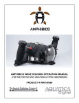
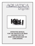
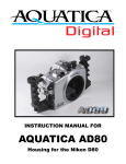
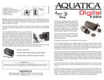
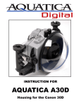
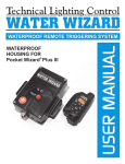
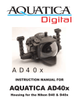
OPERATING MANUAL
FOR THE AQUATICA DIGITAL
HOUSING FOR THE SONY NEX-5
PRODUCT # 30001
FOREWORD
Thank you for having selected the AQUATICA Digital Camera Housing System for your Sony NEX-5 camera.
The AQUATICA AN-5 Digital Housing is the result of a long and continuing relationship with the most demanding underwater photographers in the world.
Each housings is machined from solid aluminum on the best 5 axis computerized machine for the utmost precision, then hand finished, quality checked
and pressure tested to a 90 meters/300 feet equivalent by a small group of specially trained individuals, each of whom takes the utmost pride and satisfaction in offering the best underwater camera housing in the world.
This Aquatica Digital Housing is designed for delivering optimum technical and optical performance from your camera while providing easy and efficient
access to all essentials functions and controls of the Sony NEX-5 Camera.
This manual assumes that the user is already familiar with the Sony NEX-5 camera. If not, please take the opportunity to read the Sony instruction
Manual and get acquainted with your camera features before attempting to use the housing.
With basic care and maintenance, your AQUATICA housing will give you a lifetime of enjoyment and satisfaction in producing underwater images.
Please read this manual carefully before using your housing for the first time and note that: when cited, the right and left position on the housing refer to
the position of your hand when using the housing
SAFETY PRECAUTIONS:
While the Aquatica AN-5 is a rugged piece of equipment. Improper transportation, handling or use of this housing might cause a flood or operating malfunction. Please, take a minute to read and follow the following precautions:
• Store and transport the housing in a sturdy, shock proof container and avoid travelling with the camera mounted inside the housing as impact forces
especially on the external push buttons will be transferred directly to the camera.
• When travelling by air, either remove the port or open the housing, internal pressure built up can push port or O-ring out of their sealing surface.
• Never change a port or open the housing in a location where sand or similar foreign material might come in contact with an O-ring.
• Use of accessories, modifications or alterations unauthorized by the manufacturer may result in flooding or poor functioning of the controls.
• Be careful when opening the housing as the pressure buildup inside the housing will exaggerate the force of the latch spring. Keep fingers clears from
the path of the latches.
• Whenever changing ports or O-rings, perform a simple seal test without the camera inside.
• Avoid scratching the acrylic, glass ports and windows, handle theses with the same care as you would your camera lenses.
• Make sure that all ports remain properly attached before rinsing the housing,
• The main O-ring seal should be maintained and cleaned on a regular basis. Read and follow the Care and Maintenance section on this manual.
• Ensure that the spring loaded secondary lock on the latch is properly engaged to prevent its accidental opening.
page 1
1-
2-
3-
4-
5-
6-
7-
8-
9-
10-
11-
12-
13-
14-
15-
16-
17-
18-
19-
20-
21-
22-
23-
24-
25-
26-
27-
28-
29-
30-
31-
On/Off lever
Shutter release button
Video on/off button
Playback button
Internal flash actuating lever
Optical bulkhead (shown with Sea & Sea type adapter)
Optical bulkhead (shown with INON type adapter)
Front flash port window
Internal flash blocking mask
Zoom/Focus control knob
Zoom/Focus internal pinion gear
Latch
Safety catch tab
Bayonet flange
Quick release tray
¼-20 camera mounting screw
Port lock lever
Hand strap lugs
Hand strap
Menu button
Four way controller dial
Enter button
Shooting tips button
LCD window port
Moisture alarm LED receptacle
¼”-20 mounting shoe for accessory
¼” -20 Tripod mounting hole.
Rubber anti skid pad
Sacrificial anode
Accessory tray mounting screw holes
Moisture Alarm (optional)
page 2
CONTROLS IN DETAIL
01. ON/OFF KNOB: Rotate to switch camera on or off
02. SHUTTER RELEASE LEVER: Press the shutter release part way to activate the camera auto focus. To release camera shutter, press all the way.
03. VIDEO ON/OFF BUTTON: Press to activate or to stop video recording.
04. PLAYBACK BUTTON: Press to activate the monitor and review images.
05.
INTERNAL FLASH ACTUATING LEVER: rotate down to turn internal flash on, or to engage the internal flash mask when using external strobe
triggered by optical fiber.
06. OPTICAL TYPE BULKHEAD CONNECTOR: (Show with a Sea & Sea type of sync cord adapter). To connect Sea & Sea type optical fiber cord.
07. OPTICAL TYPE BULKHEAD CONNECTOR: (Show with an INON type of sync cord adapter).To connect INON and other type of straight type
optical fiber cord.
08. MOUNTING HOLE FOR ACCESSORY: a 1/4”-20 TPI hole is supplied to accept a TLC accessory or TLC base ball for mounting a strobe arm or
a modeling light.
09.
FLASH BLOCKING MASK: This mask is used when external strobe are used, it blocks off stray light from the internal flash to prevent lighting up
suspended particles in front of the camera.
10. FOCUS/ZOOM KNOB: Turning allows manual focus of a single focus lens or rotation of the zoom mechanism of a zoom lens.
11. FOCUS/ZOOM PINION GEAR: Engages and operates the focus or zoom gear attached to the lens. A release lever (key # 18) is provided to
disengage the knob when removing the camera from the housing with the lens attached.
12. LATCH: This heavy duty latch is equipped with a safety lock to protect against accidental opening.
13. SAFETY CATCH TAB: This tab secures the main latch against accidental opening.
14. BAYONNET MOUNTING FLANGE: allows the mounting of different ports and extension rings on the housing.
15.
REMOVABLE CAMERA TRAY: Used to attach camera and slide in housing.
16. CAMERA MOUNTING SCREWS: this 1/4-20 screw is for attaching the camera to the removable tray.
17.
PORT RELEASE LEVER: Rotate clockwise to disengage the port lock, Press down and rotate counter clockwise to reengage the locking
mechanism when installing or removing a port or extension.
18. HAND STRAP LUGS: Two lugs are provided for the hand strap.
19. HAND STRAP LUGS: An adjustable hand strap is provided for securely handling the housing underwater.
20. MENU BUTTON: Press to activate menu display, scroll using control wheel (key #18) and select using enter button (key # 19).
21.
CONTROL WHEEL: Rotate to scroll through the camera functions and menus, press the enter button (key 19) to confirm choice.
22.
ENTER BUTTON: Press to acknowledge selected function or for accessing the shooting mode.
23. SHOOTING TIPS BUTTON: Press to display shooting tips function
24. MONITOR DISPLAY WINDOW: allow viewing of menus, information and images
25. MOISTURE ALARM LED RECEPTACLE: To accept the warning flashing LED of the optional moisture alarm.
26. ACCESSORY GRIP MOUNTING HOLES: Four threaded holes are ready to accept accessory grips.
27. TOP MOUNTING HOLES: a 1/4” X 20 hole is provided for mounting a strobes arm, focus light or accessories.
28. BOTTOM MOUNTING HOLES: a 1/4” X 20 hole is provided for mounting strobes trays or accessories.
29.
RUBBER ANTI SKID PADS: three rubber pads are provided to protect the housing and preventing it from sliding on wet decks.
30. SACRIFICIAL ANODES: A zinc anode is provided to protect your housing against salt water corrosion; it is designed to deteriorate faster than
the other strategic metal of your housing, hence the name sacrificial anodes. This anodes need to be replaced periodically by the user as needed.
31.
MOUTING HOLES FOR OPTIONAL GRIPS: Two mounting points are incorporated in the housing design; grips can be mounted on each side
of the housing.
32.
OPTIONAL MOISTURE ALARM: Two mounting holes are provided for mounting an optional moisture alarm in the housing.
page 3
FEATURES
This Aquatica Digital housing is issued from the world’s most technologically advanced underwater housing lineage, ergonomically designed to reproduce
and place all the essential camera controls under your finger tips and features the following:
A.
A newly designed lock for the port or extension mounted on the housing and to disengage the pinion gear of the housing
to facilitate removal of the camera with lens mounted.
B. A quick release tray, allowing fast and easy removal of camera.
C. Large ergonomic and easy to operate controls that replicates the camera functions.
D.
Two optical strobes connector are supplied as standard and ready to accept S-TTL strobe for easy and precise TTL exposure easily.
E.
A handy quick access lever for raising and lowering the internal flash of the camera, when using optical fiber triggering. This lever allows for
quick and simple flash to ambient light photography
F. The following controls can be easily manipulated underwater:
- Soft and predictable mechanical shutter release.
- Control wheel; it can rotate and be press down exactly replicating the one on the camera
- Quick access video button
- Focus / Zoom knob
- Quick review access
G. A comprehensive line of ports that cover the most popular lenses for underwater photography that will preserve the image quality of your
Sony E Mount lenses. Adapters will be made available in the future for mounting the larger DSLR lines of port from Aquatica.
PREPARATION OF THE HOUSING
1. Attaching the optional grips to the housing:
Optional Grips are available from Aquatica, these grips can accept accessory strobes arms should you want to mount some on them. Mounting holes are
supplied underneath the housing for attaching the grips with the supplied fasteners and Allen key. Occasionally remove the grip and lubricate the screws
to prevent them from locking on (see Care and Maintenance: of the housing).
On the bottom of the housing you will additionally find a ¼” – 20 threaded hole that can be used for mounting a tripod, accessory brackets or additional
lighting.
On the top of the housing is another ¼”-20 threaded hole for adding a focus light fixture, strobe arm or buoyancy compensating float.
2. Lubricate the Main O-ring Seal:
Before using the housing underwater always carefully inspect the Main O-ring seal in its groove on the rear half of the housing. Confirm that it is free
from scratches or foreign material. Lubricate the O-ring with a light coat of Aquatica O-ring lubricant.
When replacing the O-ring place the entire O-ring over the O-ring groove and start by pushing the O-ring in the corners. Work your way around the
O-ring making sure the O-ring is snugly sitting in the groove.
For proper handling and maintenance of O-rings be sure to read the section titled “Care and Maintenance: of the O-rings.”
PREPARATION OF THE PORTS
1. Select the correct port:
The type of photography you plan will require you to select either a flat port for macro or dome port for wide angle photography, these come in different
size and type and the lens selected will dictate the proper ports that can used. See lens chart for the suggested port and accessories.
Dome Port Extension Rings: When using a wide angle or zoom lens, the Dome Port may require the uses of an extension ring to closely match the optical
center of the dome to the entrance pupil of the lens.
2. Cleaning the port:
Dirt, grease or fingerprints on the port especially on the inside, can adversely affect the quality of the image. Acrylic ports should be cleaned with plastic
cleaner and the glass ports should be cleaned with lens cleaner. For more details, be sure to read the section titled “Care and Maintenance: of the
Ports.”
3. Lubricate the port O-ring seal:
Before using the port, remove the O-ring on the rear of the port and lightly coat it with Aquatica O-ring lubricant. For more details, be sure to read the
section titled “Care and Maintenance: of the O-rings.”
Gear installation:
Mount the focus gear over the focus ring of the lens by sliding it over the lens until it stops.
page 4
CAMERA PREPARATION AND INSTALLATION
1. Prior to installing the camera in the housing, remove the camera strap, or any object that might obstruct installation, third party camera strap
hookup should be removed from the camera prior to setting up.
2. Remove the saddle from the housing lift the rear LCD panel of the camera up and carefully place the camera on the tray.
3.
Ensure the camera is properly installed by aligning the tripod socket of the camera with the tray mounting screw. Tighten the tray mounting
screw securely while ensuring that the camera position and the LCD is not altered,
4.
Once secured in place, lower the LCD panel, it will fall back to a 15 degree angle. Lift the flash in the full up position and slide the
quick release tray back into place as per drawing at right.
An optional internal moisture alarm is available for your AQUATICA Digital housing (Product # 20023). This moisture alarm is powered by an easily replaced CR 2032 battery. Please read the instruction sheet provided for your moisture alarm prior to installing the battery.
CLOSING OF THE HOUSING: Once the camera is secure on the saddle inside the front half of the housing:
A. activate the on/off lever switch (key # 01) to confirm the camera is properly installed.
B.
Activate the flash lever to see that the flash actually shuts down and that the flash blocking mask goes all the way up
C. Inspect the main O-ring on the rear half of the housing to confirm it is clean, lubricated and properly seated for a positive seal.
D. The sealing surface on the front half of the housing is clean and free from any scratches or physical damage.
E. Close the door gently and secure the latch, verify that the locking tab is engaged. To open reverse the process, push on the locking tab and
lift the latch.
CAUTION: if you feel any resistance as you attempt to close the latch, do not force the closure. Check for any obstructions and try again.
F. To avoid any accidental opening. Always verify that the safety locking mechanisms of the latch is properly engaged prior to entering water.
MOUNTING THE PORT
Before mounting the Port on the Housing always ensure that the port O-ring is clean, lubricated and properly seated in its groove and that he sealing surface on the Housing is clean and free of physical damage.
The AQUATICA Digital AN-5 Housing features a locking bayonet mount. To mount the port or extension ring simply:
1. Place the housing on its back on a soft and steady surface.
2.
Rotate the port lock lever (Key #17) clockwise until it stops. Place the port or extension ring inside the port opening
of the housing. Align one of the four alignment notches with the opening of the housing.
3. Place your hands on opposite sides of the port or extension ring and push the port or extension ring in with even
force on both sides until you feel it snap into place. Make sure the bayonet is completely inside the housing and
rotate the Port clockwise until it stops. Do not force it, if there is too much resistance, take the port off, check the
O-ring for damage and retry
4.
Push the port lock lever (key # 17) in and rotate it counterclockwise until it stops to engage the port lock
5. Check to ensure for the proper seating and sealing of the port or extension and that it is safely locked on the housing.
Note: It is recommended that you familiarize yourself with this mount by trying it without a camera in the
housings, this will allows you to see the inside view of the bayonet mount and of the ports or extension
rings in the housing.
UNLOCK
17
17
UNLOCK
PUSH
LENS INSTALLATION
With the camera inside the housing, install the lens prepared with its gears (if needed) through the port opening in the front of the housing. When using a
gear always confirm that it is properly installed and aligned on the lens. Rotate the focus / zoom control knob to ensure that the gears are properly meshed,
that their rotation is smooth and that it does not do not grind or bind.
CHANGING A LENS (REMOVING A LENS)
Rotating lever (Key # 17) clockwise until it stops will disengage the port lock and move the
pinion gear (# Key 11) out of the way so you can remove the camera with the lens attached or
simply exchange port on the housing. Replace lens and and port if necessary, then reinstall
by reversing this procedure, finally push the port lock lever (key # 17) in and rotate it counter
clockwise until it stops to engage the port lock
11
UNLOCK
17
page 5
OPTICAL CONNECTORS
The Aquatica AN-5 housing is equipped with two optical port connectors, as well the housing is supplied
with adapter for typical straight cord used by INON and various strobe manufacturers with adapters for
angled Sea & Sea type cords, select the desired adapter and install it on the optical port base, tighten the
set screw into place with the supplied hexagonal wrench.
In order to use Optical triggering, the built-in flash of the camera need to be in the up position, this can be
done at time of installation or later by using the lever (key # 5). Select the proper sync mode you wish to
use in the camera flash menu (rear, slow, etc.).
Note: it is advisable to turn the camera and external strobe off when travelling to your dive site in order to
avoid useless drain of the camera and strobes the batteries. Also field testing as shown that mixing brand
of strobes give unreliable result and should be avoided if possible.
INON Type Straight cord
Sea & Sea Type angle
TAKING A PICTURE
Following are some basic techniques used in underwater photography. For more information and advanced photography please study the Sony
AN-5 instruction manual.
1. Rotate the control wheel to select the desired exposure mode; the chosen exposure mode will appears on the rear LCD window. Exposure Mode
options in sequence are: Programmed Auto (P), Shutter Priority Auto (S), Aperture Priority, Auto (A) or Manual Exposure (M). Scene mode and
Intelligent Auto are not recommended for use underwater, typically the manual (M) and Aperture priority (A) are the most adapted for underwater
photography
2. Control of Auto Exposure compensation is accessed via the control wheel (key # 21), by pushing the lower part of the wheel in (same as would
be done on the camera itself) this control is vital for video shooting, rotate the control wheel to select the proper exposure parameter and press the
enter button (key # 22) to accept.
Note: When shooting with strobes it is recommended that the camera be used only in Single Frame Motor Drive or there is the possibility
that the camera will fire before the flash can fully recycle.
USING THE HOUSING
Whenever changing ports or O-rings, it is highly advisable to perform a simple seal test without the camera inside. Strapping a weight to the housing and
lowering it to a depth of 30 to 50 feet of water for at least 10 minutes will assure you that the seating of the new port or o-ring is proper. This test, though
time consuming and often considered unnecessary, may save your camera equipment from irreparable water damage. Once this test is performed the
housing is now ready for the dive.
CAUTION: Never jump into the water with the housing. It is best to have the system handed to you after you have made your entry, or have it lowered gently
to you on a line. Make certain that lanyards of other equipment stay clear of the system when rinsing.
When photographing, be sure to respect the environment. Avoid damaging marine life or manipulating sea creatures to obtain a pleasing photo. The housing
is slightly negatively buoyant so that you can lay it down on the bottom, but avoid laying it on live coral or other delicate marine life.
Changing the memory card and battery
Always take care to thoroughly dry the housing before opening it to replace a memory card or
battery. Wipe the housing off with a dry towel. If possible it is suggested that the housing be blown
dried by directing an air nozzle around the main o-ring before opening.
Lift the port release lever up (key #17), to disengage internal pinion gear, then rest the housing on
its front with the lens facing down, be careful to protect the port surface, release the latch, open the
rear door and pull out the quick release tray with the camera and lens, be careful of any residual
water falling into the housing and on to the camera when the housing is opened. before reclosing
the housing, inspect the O-ring thoroughly to confirm it is clean.
11
UNLOCK
17
TRANSPORTING THE AQUATICA DIGITAL HOUSING
Store the AQUATICA Digital housing in a sturdy, shock proof container. When travelling by air, remove or loosen the port. This allows for equalization of
the air pressure inside the housing to the external air pressure. Failure to do so may cause serious damage to the acrylic ports. Avoid travelling with the
camera mounted in the housing.
page 6
CARE AND MAINTENANCE
Of the housing:
After each and every salt water dive, your housing system should be soaked or rinsed in fresh water for at least 30 minutes. During this soaking period
reach into the water and operate all the controls several times, on the return of a dive trip, given your housing a prolonged soaking in fresh water will
prevent left over salt from settling in. Be sure to inspect the housing’s main o-ring and clean it after every use. Refer to Maintenance: Of the O-rings.
To ensure that the accessory hand grips won’t fuse on to the housing due to the exposure to salt water, it is also a good practice to occasionally remove
them. Clean and lubricate the bolts with a small amount of WD-40 or add a touch of grease.
WARNING: Use WD-40 carefully, sparingly and only on metal to metal surfaces. WD-40 can damage the acrylic on the ports, the optical surfaces on lens as well as the O-rings.
Of the Ports:
Care should be taken with the Dome Port and Macro Port to avoid scratches on the lens surface. The acrylic port is softer than glass so minor exterior
scratches are often unavoidable. However, since the indices of refraction for acrylic and water are almost equal to each other, the scratches, if they are
minors, are unlikely to show up and will not seriously impair image quality. Internal scratches (air side) on the other hand must absolutely be avoided as
they do not fill in with water and will affect the quality of the image.
Clean the Acrylic dome using only products recommended for cleaning acrylic and a soft lint free cloth and glass dome with approved lens cleaning
products. Dust on the interior surfaces of the port can be removed with a soft camel hair brush or a blower brush. Caution must be taken when using
aerosol devices as not to spray the lens material with the liquid propellant as this may seriously affect the optical properties of the port. Use of pressurize
air directly from a dive tank is not recommended, the high pressure force of the air stream may easily dislodge the port lens or its O-ring, It is advisable
that ports should be removed, inspected and serviced after every dive.
Of the Latch:
The latch on the AQUATICA an-5 housing is equipped with secondary safety lock to prevent accidental opening. Always ensure that this locking
mechanism is secure. Watch for the build-up of corrosion or salt residue around the latch. This will appear as a white material. Lubricate the latch occasionally with a small amount of WD-40 to remove the corrosion or salt residue build-up.
Of the O-Rings:
The O-rings that need to be maintained on a regular basis are the main housing O-ring and the O-ring on the lens port The main O-ring should be
cleaned and inspected on a regular basis and the port O-ring should be cleaned every time a port or extension is changed or removed.
Of the sacrificial anodes:
The anode attached to the bottom parts of the housing is there to prevent corrosion due to electrolysis, as time goes, it will deteriorates and need replacement, contact your dealer for a replacement set (parts # 19220).
TO SERVICE O-RINGS ON THE HOUSING MAIN O-RING, PORTS AND EXTENSION RINGS
1.
Removing the O-ring. It is important never to use a sharp instrument when removing an O-ring as this may damage the O-ring groove
or the O-ring itself. A dull pointed object or the edge of a credit card usually works well.
NOTE: the main O-ring is inserted in an inverted V groove to prevent it from popping out, to remove, use a dull pointed object and insert in
the side of the small circular opening provided on the lower side of the rear part of the housing. Do not use sharp objects or excessive force
as this could result in damage to the sealing surface.
2. Once the O-ring is removed, it should be examined for damage. Check that it is free of nicks and cuts and that it retains its original round profile.
O-rings that appear to be damaged should be discarded immediately and replaced with new ones. Rinse the O-ring with fresh water and dry it
with a clean lint free cloth.
3. Clean the O-ring groove (where the O-ring sits) with a cotton swab. Be sure to remove any lint the cotton swab may leave behind. Inspect the
groove for any signs of damage. Wipe the sealing surface part of the housing that the O-ring seals against with a clean lint-free cloth.
4. Re-grease the O-ring with a thin layer of Aquatica O-ring lubricant until it appears to be smooth and shiny. Do not over grease it. Use just
enough grease so the O-ring will pull smoothly through your fingers. Excessive amounts of grease will only serve to attract dirt to the o-ring.
Make sure that the O-ring is properly and evenly seated in the O-ring groove.
5. To reinstall the clean and lubricated main O-ring, place the entire O-ring over the groove and start by pushing the O-ring in at each corners
then, push the O-ring at each side and finally, work in the rest of the O-ring. Never start at one end and work your way around the O-ring.
This places uneven tension on the O-ring which may cause the O-ring to stretch resulting in excess O-ring, which will have no place to go.
WARNING: Use only petroleum free O-ring lubricant such as our # 19213 Aquatica O-ring Lubricant. Petroleum based lubricant used by some
other manufacturer for their Silicone based O-rings can and will swell the material of our O-rings, this will make the O-ring more difficult to
install and can result in the O-ring being damaged or pinched resulting in dire consequences.
Internal O-rings on the housing controls are not user accessible, while these O-rings are not as susceptible to damage as they are not exposed, rinsing
properly with fresh water to flush out salt crystals and sand residues will be the proper way to assure trouble free operation, it is recommended by the
manufacturer to have the housing in for yearly maintenance. Aquatica has authorized service center in both the continental USA and Europe, prior to
sending the housing check for the closest service center to you on our website www.aquatica.ca.
page 7
A selection of ports are already available for the An-5
housing, additional ports will be introduced as newer lenses
become available for this camera system. The latest version
of the lens chart for this housing can be downloaded from our
website www.aquatica.ca , just select your housing from the
product section and click on “LENS CHART”.
Shown with the accessory grip # 30400
Aquatica AN-5 Housing
for the Sony NEX 5
# 30001-kit01
BALL HEAD ADAPTER
NOT INCLUDED*
PRODUCT # 17888
TLC to Inon ball head adapter
PRODUCT # 17692
TLC to Ikelite DS ball head adapter
* Other adapters availables
PRODUCT # 17691
TLC to Sea & Sea ball head adapter
The Aquatica AN-5 housing is available
in a kit which includes the following:
1X 30001 AN-5 housing
1X 30400 Accessory tray and grip
1X 17514 TLC 3 section arm
MADE IN CANADA
www.aquatica.ca
Technical Lighting Control
Shown with two accessory grips # 30400
www.aquatica.ca
WARRANTY
PLEASE READ CAREFULLY
One year Limited Warranty.
Thank you for purchasing an AQUATICA manufactured product! Your AQUATICA housing is handcrafted by a
small group of specially trained individuals - each of whom takes the most pride and satisfaction in offering you
the best underwater camera housings in the world. All AQUATICA products are guaranteed against defects in
material or workmanship for (1) one full year from the date of purchase for consumer use. these same products
when used commercially will carry a 90-day warranty. No statutory warranty applies. Camera housed in AQUATICA
housings are not covered under this warranty and ANY WATER DAMAGE SUSTAINED DUE TO INSTALLATION
ERROR OR ANY OTHER REASON IS NOT THE RESPONSABILLITY OF AQUATICA. Therefore the appropriate
insurance should be maintained by the user.
Warranty does not apply to replaceable seals or damages to impacts or abrasive surfaces. Warranty applies
only to products purchased from authorized AQUATICA dealers and does not extend beyond the original retail
purchaser. Unauthorized modifications or repairs will automatically void this warranty. this applies to removal of
serial numbers and AQUATICA identification labels.
To obtain service during or after the warranty period you must notify AQUATICA at 514-737-9481 for the shipping procedure and ship BY REGISTERED MAIL (INSURED) ONLY, enclosing your proof of purchase to:
AQUATICA
3025 De Baene
Montreal (Quebec)
H4S 1K8
Mark clearly on your package and shipping document “Canadian goods returned for repair”
Do not ship by any other means unless authorized by Aquatica.
Unauthorized packages will be refused.
YOUR SERIAL NUMBER_______________________________
page 12