1
NL
Gebruiksaanwijzing
GB
Manual
D
Betriebsanleitung
F
Mode d'emploi
CONTENT
PREFACE .......................................................................................................................................... 50
Purpose of use .................................................................................................................................. 52
Safety instructions and danger warnings........................................................................................... 53
Safety provisions ............................................................................................................................... 54
Devices and the environment ............................................................................................................ 54
1. GENERAL ..................................................................................................................................... 55
2. TECHNICAL DATA ....................................................................................................................... 56
3. INSTALLATION ............................................................................................................................. 58
3.1 Unpacking ............................................................................................................................ 58
3.2 Placement preparation ......................................................................................................... 58
3.3 Water connection ................................................................................................................. 59
3.3.1 Water treatment......................................................................................................... 59
3.3.2 Stand alone pump set ............................................................................................... 59
3.3.3 Base cabinets............................................................................................................ 59
3.4 Electrical connection ............................................................................................................ 60
3.5 Drip tray discharge ............................................................................................................... 61
3.5.1 Applying info sticker .................................................................................................. 61
3.6 Applying recipe strips ........................................................................................................... 61
3.7 Removing the transit safety ................................................................................................. 61
3.8 Standard recipe settings ...................................................................................................... 62
3.9 Filling the canisters .............................................................................................................. 63
3.10 Positioning ......................................................................................................................... 64
3.10.1 Positioning on the work top ..................................................................................... 64
3.10.2 Base cabinet ........................................................................................................... 64
3.10.3 Base cabinet with coffee residue outlet ................................................................... 64
4. FIRST USE .................................................................................................................................... 65
4.1 First use / rinsing the hot water system ............................................................................... 65
4.2 Operator / service menu settings ......................................................................................... 65
5. OPERATING PANEL..................................................................................................................... 66
5.1 Operating panel (front) ......................................................................................................... 66
5.2 Service panel (inside the door) ............................................................................................ 67
6. MENU STRUCTURE ..................................................................................................................... 68
6.1 The operator menu .............................................................................................................. 68
6.2 Quick recipe ......................................................................................................................... 70
7. DAILY USE .................................................................................................................................... 71
7.1 Filling (up) the canisters ....................................................................................................... 71
7.2 Preparations ........................................................................................................................ 71
7.3 Dispensing cups/goblets ...................................................................................................... 72
7.3.1 Strength adjustment .................................................................................................. 72
7.4 Dispensing jugs ................................................................................................................... 73
7.4.1 Jug volume ................................................................................................................ 73
7.5 Payment systems (optional) ................................................................................................ 74
7.5.1 Coin system .............................................................................................................. 74
7.5.2 Coin changer ............................................................................................................. 75
48
12/2009 Rev. 0.2
7.6 Automatic disabling functions .............................................................................................. 76
7.7 Display messages during use .............................................................................................. 76
8. MAINTENANCE ............................................................................................................................ 77
8.1 Door switch .......................................................................................................................... 77
8.2 Rinsing programmes ............................................................................................................ 77
8.3 Cleaning daily ...................................................................................................................... 78
8.3.1 Cleaning the brewer unit .......................................................................................... 78
8.3.2 Emptying and cleaning the waste bin........................................................................ 78
8.3.3 Cleaning the mixer unit ............................................................................................. 79
8.4 Weekly cleaning ................................................................................................................... 80
8.4.1 Cleaning the brewer lter / brewer chamber ............................................................. 80
8.4.2 Brewer lter cleaning................................................................................................. 81
8.4.3 Replacing the brewer lter ........................................................................................ 81
8.4.4 Cleaning the coffee grinder ....................................................................................... 82
8.4.5 Removing the entire brewer ...................................................................................... 82
8.4.6 Cleaning the mixer unit ............................................................................................. 83
8.5 Monthly cleaning .................................................................................................................. 84
8.5.1 Cleaning the brewer unit ........................................................................................... 84
8.5.2 Cleaning the mixer extraction lter ............................................................................ 85
8.6 Cleaning the canister(s) ....................................................................................................... 86
8.6.1 Instant canister(s)...................................................................................................... 86
8.6.2 Bean canister ............................................................................................................ 86
8.7 Other maintenance .............................................................................................................. 87
9. SETTING THE SERVICE MOMENT ............................................................................................. 88
10. TEMPERATURE SAFETY DEVICE ............................................................................................ 89
11. TRANSPORT / STORAGE.......................................................................................................... 89
12. TROUBLESHOOTING ................................................................................................................ 90
13. ORDERING CONSUMABLES AND ACCESSORIES ................................................................ 90
DIMENSIONS
OptiFresh 1,2 and 3 bean ................................................................................................................ 186
OptiFresh 4 bean ............................................................................................................................. 187
OptiFresh 1, 2, 3 bean Coin mechanism ......................................................................................... 188
OptiFresh 4 bean Coin mechanism ................................................................................................. 188
OptiFresh 1, 2, 3 bean Coin changer .............................................................................................. 189
OptiFresh 4 bean Coin changer ...................................................................................................... 189
Base cabinet standard ..................................................................................................................... 190
Base cabinet with litter bin ............................................................................................................... 190
12/2009 Rev. 0.2
49
© 2009 Animo®
Introduction
First we would like to congratulate you with your purchase of one of our products. We hope you will
enjoy using it.
All rights reserved.
No part of this document may be reproduced and/or made public in print, microlm, electronic media
or any other form without the manufacturer's prior consent. This also applies to the corresponding
diagrams and/or charts.
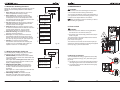
Models
These instructions for use are for the following devices:
Animo retains the right to alter parts at any given time without prior or immediate announcement to the
consumer. The content of this manual can also be changed without any prior warning. This manual is
valid for the standard model of the device. Animo can therefore not be held liable for possible damage
resulting from specications deviating from the standard model for the device supplied to you.
OptiFresh 1 bean
OptiFresh 4 bean
OptiFresh 2 bean
OptiFresh 3 bean
This manual does not provide information on settings, maintenance work or repair. If you would like
any information regarding this, please contact the technical department of your supplier.
This manual was created with the utmost care, but the manufacturer cannot be held responsible for
any mistakes in this document or their consequences.
Please carefully read the instructions in this document: they provide important
instructions on safety during installation, use and maintenance. Keep this
document in a safe place so that you can consult it at all times.
Coin mechanism (option)
PREFACE
OptiFresh 1 bean
Objective of this document
This document provides directions for use for authorised staff to safely use and maintain this device.
OptiFresh 4 bean
OptiFresh 2 bean
OptiFresh 3 bean
- Authorised staff is considered to be those who operate and maintain the device and can solve small
malfunctions.
All chapters and paragraphs are numbered. The various gures referred to in the text can be found in
the gures section at the beginning of the manual or with the corresponding subjects.
Pictograms and symbols.
CAUTION
General indication for: IMPORTANT, CAUTION or REMARK.
WARNING
Warning for possible severe damage to the device or injury.
50
12/2009 Rev. 0.2
12/2009 Rev. 0.2
51
Purpose of use
Safety instructions and danger warnings
This device can only be used for preparing hot drinks.
Use for any other purpose is inadmissible and can be dangerous.
The manufacturer cannot be held liable for any damages caused by use for any other purpose than
what is described here or by incorrect operation.
This device meets the prescribed safety provisions.
Individuals can be injured and material damage can be caused by inappropriate use.
Before the device can be used safely, the following warnings and safety instructions must be
oserved:
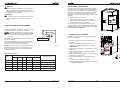
Service and technical support
For information regarding specic settings, maintenance and repair work, which is not included
in this document, please contact your dealer. Write down in advance the following data for your
device indicated with a #. The below information can be found on the type plate on your
device.
Instructions for use
Please carefully read these instructions before using the device. It is safer for you and
will prevent damage to the device.
Please adhere to the order of the following actions. Always store these instructions for
use close to the device.
A - Model indication #
B - Article number #
C - Machine number #
D - Electrical connection
E - Frequency
F - Power
A
B
Animo
Coffee- and teamakingsystems
........................
C
........................ / ...........................
........................ V 50-60Hz ....................W
D
MADE
IN
E
HOLLAND
F
Guarantee provisions
The guarantee provisions that apply to this device are part of the general terms of delivery.
Directives
This device meets the following EEC directives:
EMC 92/31/EEG &
93/68/EEG
LVD 73/23/EEG.
RoHs 2002/95/EEG
WEEE 2002/96/EEG
Installation
• Place the device at work top height on a rm, at surface so that it can be connected to the mains.
• Plug the device into a safety-grounded power outlet.
• Position the device so that it cannot cause any damage in case of any leakage.
• Never tilt the device. Always position and transport the device upright.
• Some water will always remain in the heating system, so never place the device in a room where
the temperature can fall below freezing.
• Always observe local regulations and use approved materials and parts.
• When reinstalling the device, please follow the 'Installation' chapter.
Use
• Inspect the device before use and check whether it is in any way damaged.
• The device must not be submerged or hosed down.
• Never operate the buttons with a sharp object.
• Keep the operating controls free of dirt and grease.
• If the device is not used for a long time, it is advisable to unplug the device and shut down the
water supply.
FOOD1935/2004/EEG
Conditions of the environment
Some water will always remain in the heating system. Therefore never place the device in an area
where the temperature can drop below freezing. The operation of this device is guaranteed up to an
ambient temperature of 40°C.
Recommended maintenance products
Descaler : Animo scale remover
Detergent : Animo coffee fur remover
See Chapter 13 for ordering these maintenance products.
Maintenance and solving malfunctions
• Overdue maintenance of the heating system can lead to high repair costs and can render the
guarantees invalid.
• Do not leave the device during maintenance work.
• Have all repairs done by trained, authorised service engineers.
• If the device must be opened up because of faults or (cleaning) work, make sure that it is
unplugged.
• If the safety instructions are not followed, the manufacturer cannot be held responsible for any
resulting damage.
Recommended ingredients
Brewer only use coffee beans
Mixers
only use instant products
52
12/2009 Rev. 0.2
12/2009 Rev. 0.2
53
Safety provisions
1. GENERAL
This device has the following safety provisions:
Door switch (1-16)
The machine has a door switch that automatically switches off the machine when the door is opened.
[ Out of order Door open ] The machine can be switched on whilst the door is open (for example for
cleaning) by inserting the supplied service pin in the door switch.
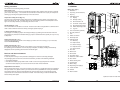
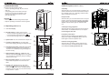
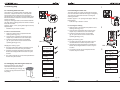
Major parts (g.1)
1. Illustration
4.1
2. Cups tray (can be folded in)
3. Drip tray
Temperature safety device (g. 1-6)
The device has a temperature safety device that is accessible from the outside. It is located at the
back of the device (g. 1-6). The safety device turns off the heating element if the temperature is too
high. This is usually caused by not descaling the device in time.
On/off switch (g. 1-18)
The on/off switch turns the device on and off. The device can still be charged after it is switched off! In
order to ensure that the machine is entirely uncharged, please unplug it.
1
4.1
Display
4.2
Strength setting
4.3
Drink selection 12x
4.4
Correction / Stop button
4.5
Drink dispensing button
4.6
Water dispensing button
4.7
Jug lock
4.3
5
4.4
4
2
5. Coin mechanism (optional)
C switch (Cancel) (g. 1-4.4)
The dosages of a coffee jug recipe can be stopped simply by pressing the Cancel button. After the
Cancel button is pressed, the selected coffee jug recipe is cancelled and the quantity for only one cup
is dispensed.
4.7
4.2
4. Operating panel
4.5
6. Dry-boil protection
7. Fan
4.6
3
8. Water connection
9. Electricity lead
Display warnings (g. 1-4.1)
Technical malfunctions are shown on the display by means of an error code (e.g. E1). In that case,
read 12. Troubleshooting.
Display warnings (g. 1-4.1)
If the drip tray is too full, this is shown on the display [ Out of order Drip tray full] and
the operating panel is disabled. Once the drip tray is emptied, the display message automatically
disappears and the operating panel becomes functional again.
10. Operator panel
10.1 Stand-by
23
22
10.2 Open brewer
10.3 Clean mixer(s)
6
10.4 Operator menu
10.5 Clean brewer
7
21
11. Door lock
12. Brewer unit
20
Devices and the environment
13. Drink outlet
19
Packaging materials
14. Hot water outlet
In order to prevent that your new purchase is damaged, the machine is carefully packaged.
The packaging does not harm the environment and mainly consists of the following materials:
15. Waste bin coffee residue
• Corrugated cardboard
17. Boiler draining tube
• Filler elements made of polyurethane foam >PUR< covered in a polyethylene lm >PE-HD<.
Contact the waste depot of your local council for the removal of these materials.
18. On/off switch
18
8
16. Door switch
Not one device lasts forever. If you wish to replace your device, it is usually taken back in consultation
with your dealer. If not, please contact your local council for the possibilities of re-using the materials.
All synthetic parts are coded in a standardised way. Device parts such as circuit boards and their
components come under electric and electronic waste. The metal casing is made of stainless steel
and be entirely taken apart.
17
10
11
16
10.1
10.5
19. Mixer unit(s)
10.4
20. Dispensing bent pipe(s)
Replacement of the device
9
21. Instant canister
22. Grinder
12
10.2
13
14
15
10.3
23. Bean canister
Fig. 1
OptiFresh 4 bean is model shown
54
12/2009 Rev. 0.2
12/2009 Rev. 0.2
55
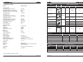
2. TECHNICAL DATA
TABLE 1
Model
OptiFresh bean
OptiFresh Hot & Cold
Capacity Coffee
Hour capacity per cup of 120 ml
Preparation time per cup of 120 ml
Preparation time jug (12 x 120ml cups)
Preparation time jug (7 x 200ml cups)
Canister capacity
125 cups
abt. 29 sec.
5’.50”
3’.23”
see table 1
125 cups
abt. 29 sec.
5’.50”
3’.23”
see table 1
Capacity Cocoa
Hour capacity per cup of 120 ml
Preparation time per cup of 120 ml
300 cups
abt. 12 sec.
300 cups
abt.12 sec.
Canister / waste bin capacity
Ingredient
Dimensions
Volume
Product
6,4 ltr.
2500 gr.
Coffee beans
300 cups
(à 8 gr)
OptiFresh model
1-2-3-4
2200 gr.
-
2
Cocoa
3400 gr.
170 cups
2
Milk/ Topping
1000 gr.
-
3-4
1600 gr.
80 cups
3-4
Sugar
2000 gr.
-
4
Coffee [ instant ]
500 gr.
325 cups
2-3-4
240 cups
1-2-3-4
Milk/ Topping
5,1 ltr.
Capacity hot water
Hour capacity per cup of 120 ml
Preparation time per cup of 120 ml
Preparation time jug (12 cups)
Hour capacity hot water
Boiler volume
Boiler heating time
300 cups
abt. 6 sec.
abt. 75 sec.
abt. 36 liter
3 liter
5 min.
300 cups
abt. 6 sec.
abt. 75 sec.
abt. 36 liter
3 liter
5 min.
Electrical system
Voltage
Frequency
Total power
Heating element power
Fuse
Safety class
Internal circuit
Power consumption
1N~ 220-240V
50-60Cy
3275W
3200W
16 A
I
24VDC
see table 3
1N~ 220-240V
50Cy
3500W (incl. cooling unit)
3200W
16A
I
24VDC
Cocoa
2,3 ltr
7,7 ltr.
Waste bin
TABLE 2
Water system
Water hardness
Water conductivity
Water connection
Adjustable water temperature
Min.-max water pressure
Flow pressure
Cups/120 ml
Weights (kg)
Model
min. 5°dH
70 Siemens/cm
3/4" external pipe thread
70 - 97 °C
0,2 MPa (2 bar) - 1 MPa (10 bar)
6 l. / min.
empty
lled*
OptiFresh 1 bean
35
40
OptiFresh 2 bean
35
44
OptiFresh 3 bean
35
43
OptiFresh 4 bean
39
47
in packaging
* = full ingredient canisters and boiler
Materials
Casing / door
Boiler
Drip tray
stainless steel
stainless steel 18/10 (1.4404) (AISI 316L)
plastic <PS> black
Dimensions
Weight
see last pages of this document
see table 2
TABLE 3
Power consumption [Wh]
Model
OptiFresh 1, 2, 3 & 4
1
without dispensing /
2
To reach
operating
temperature
Operating
mode 1
Operating
mode 2
For each hour
stand by 3
286
67
100
30
dispensing of 200ml coffee each 30 minutes /
All technical details are subject to change
56
12/2009 Rev. 0.2
12/2009 Rev. 0.2
57
3
boiler kept warm on 60°C
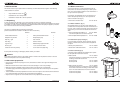
3. INSTALLATION
3.3 Water connection
This device should only be placed and connected by an authorised service engineer. The following
must be taken into account:
•
•
•
Only suitable for indoor use
Unsuitable for use in damp areas
Unsuitable in areas with a risk of explosion
Connect the device to a well accessible tap with air
valve, which can be turned off quickly in case of problems. The minimal water pressure must not fall below 1
bar (at 5 l/min ow pressure).
60°C
If necessary, the OptiFresh can be connected to hot
water. We explicitly advise you to use a special hot
water connection tube (g. 2).
3.1 Unpacking
Hot water connection tube
In order to prevent any damage to your new purchase, the device is carefully packaged.
You should carefully remove the packaging without using any sharp objects. Check whether the device
is complete. In order to protect the device, the stainless steel sections are partly wrapped in protective
foil. This foil should be removed during installation.
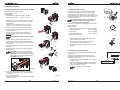
3.3.1 Water treatment (g. 3)
The device is supplied with the following accessories:
(Some accessories are located in the litter bin next to the brewer.)
Number
Number
Art. No. 08175.
We explicitly advise you to use a water softener and/
or water lter if the tap water has been chlorinated or is
too hard. This increases the quality of the drink and will
ensure that you do not have to descale the device too
often.
Filter system Brita AquaQuell 1.5
Art. No. 99681
incl. lter template and connection tube set
Coffee residue litter bin
1
Extra permanentlter brewer
1
Reception tray brewer
1
Recipe strips (set)
1
Drip tray + grid
1
User manual
1
3.3.2 Stand-alone pump set (g. 4)
Door keys
2
Service manual
1
Filter template Brita AquaQuell 1.5
Art. No. 07996
Fig. 3
Jug lock keys
2
Disassembly equipment lter
1
If no xed water connection point is present near the
machine, a stand-alone pump set can be supplied as
an option.
Service pen
1
1.5 m Connection hose
1
Water pump stand-alone
Art. No. 93500
1
Water tank 18 litre stand-alone
Art. No. 01013
Coffee fur remover (sachet)
1
0.5 m Drain hose (Drip tray)
Fig. 2
3.3.3 Base cabinets (g. 5)
If some parts are missing or damaged, please contact your dealer.
WARNING
Some water will always remain in the heating system. Therefore never place the device in an area
where the temperature can drop below freezing.
3.2 Placement preparation
• Place the device at work top height on a rm, at surface so that it can support the weight of the
(lled) device.
• Make sure that the device is level and cannot cause damage in case of any leakage.
• Make sure that the ventilation openings at the back of the device are not obstructed.
• The water supply and electricity plug should be no further than half a meter away from the position
of the device.
• These installation technical preparations must be out sourced by the user and should be carried out
by an authorised tter according to the general and local regulations.
• Only the service engineer can connect the device to the prepared connection points.
A number of base cabinets are available as an option
for the OptiFresh fresh brew machine.
Fig. 4
Base cabinet
Art. No. 65070
Prepared for building in a stand-alone pump set and
for fitting a water filter at the back.
Work top large
Work top small
Art. No. 03390
Art. No. 03357
Base cabinet with transit
Art. No. 65060
Prepared for building in a collection unit for collecting
more coffee residue and for fitting a water filter at the
back. This base cabinet does not have a drawer!
Transit work top large
Transit work top small
Art. No. 65031
Art. No. 65032
Fig. 5
58
12/2009 Rev. 0.2
12/2009 Rev. 0.2
59
3.4 Electrical connection
3.5 Drip tray discharge
WARNING
Supply voltage and frequencies can differ per country.
Check if the appliance is suitable for connection
to the local power mains.
Check if the details on the type plate (g. 6) correspond.
Connect the appliance to an earthed wall socket.
Premium coffee makers &
beverage equipment
OptiFresh bean [ type ]
[ Art. No. ] /
[ Mach. No. ]
_______ V 50-60Hz ______ W
MADE
The earthed wall socket and the fused group with a
main switch belong to the electrical installation.
No heavy machines that could cause variations in
power when being switched on, can be connected to
this group.
A machine with power current (two or three phase) is
supplied from the factory without plug. At delivery, the
machine must be provided with an electrically suitable
plug as advised and provided by the installer.
Depending on the appliance's electrical set-up, it must
be connected as below.
(g. 7)
(g. 8)
(g. 9)
(g. 10)
1
2
3
3
N~
N~
N~
~
230V
400V
400V
230V
IN
3.5.1 Applying info sticker
Apply (if desired) the information sticker (Figure 11)
next to the control panel so a user easily can see which
buttons to push.
HOLLAND
2
KOFFIE
KAFFEE
CAFÉ
4
Fig. 6
Gr/Ye - Earth
3
Blue
(PE)
- Neutral (N)
Brown - Live
(L)
Fig. 7
Gr/Ye - Earth
Blue
4
Brown - Live 1 (L1)
3.6 Applying recipe strips
Black - Live 2 (L2)
The factory does not yet apply the recipe strips next to
the buttons. The device is always delivered together
with a sheet of various recipe strips.
Please slide the recipe strip that is applicable to your
situation in the window next to the corresponding button
(g. 12).
Section 3.8 Standard recipe settings will show you
which recipes (drinks) correspond to the factory setting.
The service appendix (chapter 3) describes how every
individual recipe (drink) can be set. After you set a
modied recipe, make sure you slide the appropriate
slide-in strip into the window next to the corresponding
button.
If your dealer took the service attachment away after
installing the device, then please contact your dealer.
Gr/Ye - Earth
Blue
5
(PE)
- Neutral (N)
Brown - Live 1 (L1)
Black - Live 2 (L2)
Gray - Live 3 (L3)
Fig. 9
Gr/Ye - Earth
(PE)
Brown - Live 1 (L1)
4
Fig. 11
(PE)
- Neutral (N)
Fig. 8
1. The GREEN/YELLOW colored wire [ EARTH ] should
be connected to the terminal which is either marked
with the letter [ PE ], the "earth" symbol ( ), or
colored green/yellow.
2. The BLUE colored wire [ NEUTRAL ] should be
connected to the terminal which is either marked with
the letter [ N ] or colored black.
3. The BROWN, BLACK and GRAY colored wire
[PHASE ] should be connected to the terminal which
is either marked with the letter [ L1, L2 and L3 ].
COFFEE
3
(3 core cable)
(4 core cable)
(5 core cable)
(4 core cable)
The following points should be observed when wiring
a new plug:
1
It is possible to t a waste hose to the drip tray.
In order to do so, please remove the synthetic plug from
the connection at the back (g. 11) and apply the waste
hose.
Black - Live 2 (L2)
Fig. 12
Gray - Live 3 (L3)
Fig. 10
3.7 Removing the transit safety
The brewer has been secured at the factory for safe
transportation.
The transit safety must be removed before you start using the device (g. 13) so that the brewer can be taken
out of the machine for cleaning.
Attention: tighten the screw that xed the transport
safety again.
If the installation instructions are not met,
the supplier cannot be held liable for any
consequences.
Fig. 13
60
12/2009 Rev. 0.2
12/2009 Rev. 0.2
61
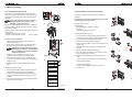
Canisters
Table 1
3.9 Filling the canisters
OptiFresh BEAN 1
OptiFresh BEAN 2
OptiFresh BEAN 3
OptiFresh BEAN 4
1
Coffee beans
Coffee beans
Coffee beans
Coffee beans
3
-
Chocolate
Chocolate
Chocolate
4
-
-
Topping
Topping
5
-
-
-
Instant Coffee
Fill the ingredient canisters with the relevant instant
product according to table 1 (left).
CO
BE FFEE
AN
S
3.8 Standard recipe settings
Coffee bean canister
1. Open the bean canister (g. 14) with the key.
2. Fill the canister (g.15) with coffee beans.
3. Close the canister again.
Fill the transparent canister only with
coffee beans!
1
1
1
1
3
3
4
3
4
5
Fig. 14
Optional recipes #
Coffee black
Coffee black
Coffee black
2
-
Hot chocolate
Coffee Milk
Coffee Milk
3
-
Coffee chocolate
Hot chocolate
Hot chocolate
4
-
-
Coffee chocolate
Coffee chocolate
5
-
-
Cappuccino
Latte Macchiato
6
-
-
Wiener Melange
-
7
-
-
Latte Macchiato
Coffee Latte inst.
8
-
-
-
Chocolate Milk
9
-
-
Espresso inst.
10
-
-
-
Wiener Melange inst.
11
-
-
-
Cappuccino inst.
12
Hot Water
Hot Water
Hot Water
Hot Water
Espresso
Espresso
Espresso
Espresso
Double Espresso
Double Espresso
Double Espresso
Espresso Choc
Jug Coffee
Espresso Chocolate
Espresso Chocolate
Coffee Latte
Jug Coffee
Chocolate Milk
Coffee inst. Milk
Jug Hot Water
Hot Milk
Hot Milk
Coffee Latte
Coffee Cremé inst.
Jug Coffee
Wiener Melange
Jug Hot Water
Latte Macchiato inst.
Jug Hot Water
JUG key switch
JUG direct choice
Fig. 15
Instant canisters
1. Open the device lid (g. 16).
2. Turn the dispensing outlet(s) into a horizontal position.
3. Move the canister(s) forward and take them out of
the device.
4. Fill the canister(s) with the appropriate products
(g. 17). See table 1 on the left.
5. Place the canister(s) back in the right order.
Fig. 16
T
Coffee black
TAN
1
Make sure that the drive mechanism of the
canister falls over the cog in the back wall and
that the fastening ridge goes into the hole of
the plate (g. 18).
6. Turn the dispensing outlet(s) back to their correct
position (g. 19).
INS
Standard recipes
Button
Fig. 17
Fig. 18
Cappuccino
Water dispensing button (right)
Jug Coffee
Jug Coffee inst.
inst. = Recipe made with instant coffee
Jug Hot Water
Fig. 19
# = can be programmed by dealer only
62
12/2009 Rev. 0.2
12/2009 Rev. 0.2
63
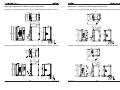
3.10 Positioning
4. FIRST USE
3.10.1 Positioning on the work top
1. Position the device on an appropriate at work area.
2. Allow an area of at least 11 cm to the left of the
device so that the door can be opened.
3. Allow an area of at least 22 cm above the device so
that the lid can be opened all the way.
4. Check whether the specications of the type plate
correspond to the mains voltage.
5. Connect the device to the water mains with the
supplied connection tube.
6. Close the door and place the drip tray under the
machine. It is possible to t a waste hose on to the
drip tray (chapter 3.5). Remove the synthetic plug
and slide the hose on.
7. The device is now ready for rst use.
Before using the device for the rst time,
chapter 3. INSTALLATION must be completed.
• During its rst use, the device works according to its standard factory settings.
• The various settings can be modied later by trained, authorised service staff.
Please see the separate service appendix, chapter 2.2. THE SERVICE MENU.
• This chapter is about rinsing the hot water system if the device is about to be used for the rst time
or if the device has been out of operation for more than 1 week, for example after the holidays.
4.1 First use / rinsing the hot water system
1. Turn the water tap open and check whether the swivel connections do not leak.
2. Plug the device into an earthed socket.
3. Turn the device on by switching the ON/OFF switch (g. 1-18) on. The display lights up and
there is a beeping sound.
4. The display rst shows the following words [Out of order, Boiler Filling] and then
[Out of order, Boiler Heating]. During the heating phase, the settings of the device
can be adjusted as described in the next chapter 4.2.
5. After approx. 5 minutes the device has heated up and the following words appear
[Make your choice].
6. Place an empty cup of at least 120 ml under the relevant outlet and select your drink.
7. The drink in question is prepared. Please discard the rst 2 cups of every choice of drink.
8. Again make a choice of drink and check whether the taste and quantity is appropriate. Repeat this
for every drink. If taste and quantity are ne, then the device is ready for use.
9. If the taste and/or quantity do not meet your wishes, please read chapter 6.2 Quick recipe.
3.10.2 Base cabinet (g. 20)
Follow the instructions provided with the base cabinet.
4.2 Operator / service menu settings
Fig. 20
3.10.3 Base cabinet with coffee residue outlet (g. 21)
This base cabinet is designed to collect large quantities
of coffee residue. The residue is led into the base
cabinet through a (prepared) opening in the bottom
section of the machine and is collected in a 37 litre
collection bucket.
Follow the instructions provided with the base cabinet.
Fig. 21
64
12/2009 Rev. 0.2
The following data must be set in the operator and service menus immediately after the machine's
rst use. The language factory setting is English.
Operator menu: press
on the service panel at the inside of the door.
1.1 Clock
1.1.0 Time
(present time)
1.1.1 Date
(present date)
1.7 PIN-code
(see chapter 2.1 of the service appendix)
2.4 Settings
(Settings)
2.4.0 Language
(Language )
2.6 Descaling / lter
2.6.0 Time for service (descaling / lter counter)
again on the service panel.
Leave the menu by pressing
Study the rest of the setting options of the service menu later.
The device is now ready for use.
12/2009 Rev. 0.2
65
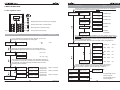
5. OPERATING PANEL
5.2 Service panel (inside the door)
The device has two operating panels.
• The front operating panel (g. 22) is for normal
daily use.
• The operating panel at the inside of the door
(g. 23) can be used by the operator to gain
access to the operator and service menus
(only with PIN code).
A. Standby
With this button you can set the device on standby. The
selection buttons are turned off and the boiler is kept at
60°C. Display: [Not in use – Standby]. Push this button
again to reactivate the machine.
B. Open brewer
CAUTION
• Never operate the buttons using a sharp object.
• Keep the operating controls free of dirt and grease.
With this button you can set the brewer unit in the 'open'
position, so that the upper brewer section can be taken
out for cleaning. See chapter 8.5 Cleaning the brewer
section. Push this button again to close the brewer
unit.
5.1 Operating panel (front)
C. Mixer(s) rinsing programme
With this button the rinsing programme for the mixer(s)
will be started. For detailed instructions, see chapter
8.4 Cleaning the mixer unit.
A. Illuminated Display
B. Strength setting for coffee, milk and sugar.
You can choose the ingredient for which you wish
.
to set the strength with the Set button
You can set the strength with the +/- button.
A
H
A
C. Option button 12x, set as mentioned in chapter 3.8
B
D. Correction / Stop button for correcting made
choices and stopping (aborting) the dosage of a jug.
C
E. Drink dispensing button + LED. Blue LED ashes
to indicate dispensing position of the goblet/cup.
The LED is on consistently during the dosage until
the drink is ready.
+ LED. Blue LED
F. Water dispensing button
ashes to indicate dispensing position of the goblet/
cup. The LED is on consistently during the dosage
until the drink is ready.
G. Menu navigation buttons 7 to 10 have a second
function after the operator menu has been activated.
H. Jug lock, After activating the key, all recipes
pictogram can be used as a jug
showing the
button. After the choice of drink, the display shows
how many cups are made. You can set the number
of cups with the +/- button.
66
With this button the Operator menu appears on the
display. See chapter 6.1 Operator menu. Press this
button again to leave the Operator menu.
D
E. Brewer rinsing programme
G
1
7
2
8
3
9
4
10
With this button you start the rinsing programme for
cleaning the brewer. For detailed instructions, please
see chapter 8.3 Cleaning the brewer unit.
B
C
Fig. 23
5
11
6
12
D
E
E
D. Operator menu button
F
Fig. 22
12/2009 Rev. 0.2
12/2009 Rev. 0.2
67
Operator menu structure
6. MENU STRUCTURE
Range
Use this menu to maintain the counter. The reset function is only available if
it has been activated by the service engineer.
6.1 The operator menu
.
'("$
.
'(
.
'(
.
'(
Escape (back without conrming any changes)
Previous (menu item / increase value)
..
'$"$
Next (menu item / decrease value)
Enter (conrm menu choice)
Fig. 24
0-99999 cups
t
0-99999 cups
2
0-99999 cups
"%
0-99999 cups
14
0-99999
9,$
.&
'$"$
Operator menu structure
Range
> Yes
No
s$
> Yes
&
u"(
&'(
)(
hour : min
! dd - mm - yyyy
The machine can be set automatically. The main switch must be on.
If the machine is turned off by the timer, the machine is automatically
set to standby. The boiler then keeps the water at 60°C and the
operating panel is disabled.
4%$
To be continued
on the next page
9t
++ ++ "
++ 68
if available!
The quick recipe menu is only available if it has been activated by the service
engineer. It allows you to easily set the volume and strength of coffee, milk and
sugar per recipe (drink button) yourself. Only the ingredients that apply to the
recipe in question are visible.
For more information about the use of the quick recipe, see chapter 6.2.
Please set the present date and time. The machine does not
automatically adjust from winter to summer time and vice versa.
0-99999
Factory setting
If your machine has a payment system (optional), you can now
change the machine's setting from free to paid.
t$($%
Factory settings
&'(
)(
00:00-23:59
00:00-23:59
00:00 = not active
00:00-23:59
00:00-23:59
00:00 = not active
00:00-23:59
00:00-23:59
00:00 = not active
12/2009 Rev. 0.2
/"("
50-200 ml
120 ml
/++,-
-20% +20%
0%
,
-
-20% +20%
0%
.
/,.-
-20% +20%
0%
&
((%,&-
-20% +20%
0%
0
"%,0-
-20% +20%
0%
Once the permanent lter of the brewer unit reaches the maximum
number of brews, this lter must be replaced. After replacing the
permanent lter, reset the 'replace brewer lter' indication.
0
2+
'$"
3
+4
78888
5
26
26
12/2009 Rev. 0.2
'$"8
Only applicable for the
service engineer.
Only applicable for the
service engineer.
69
7. DAILY USE
7.1 Filling (up) the canisters
1
The quick recipe menu is only available if it has been
activated by the service engineer.
If the volume is increased, the coffee strength
is automatically proportionately adjusted.
Ingredients such as topping and sugar are
also adjusted automatically.
If after you set the volume, you are not satised
with the strength of the coffee, you can adjust
the quantity of ground coffee. Of course, other
ingredients like topping and sugar can also be
adjusted separately.
Coffee bean canister
1. Open the bean canister (g. 26) with the key.
2. Fill the canister with coffee beans.
3. Close the canister again.
Fill the transparent canister only with
coffee beans!
2
:;<
wKAO> FBOAIB
3
:;<;<
v?@@BB XD> MRF
:;<;<;G
vKI J?DKCB
4
vKI J?DKCB
:LGCD
:TGCD
:;<;<;:
v?@@BB
:;<;<;<
Q?IIANR
5
Q?IIANR
:;<;<;T
MKRVF
GS
WTS
1. Open the operator menu (g. 25)
2. Go to 1.4 Quick recipe and press enter.
3. Go to the recipe you wish to change Recipe: Coffee
Mlk Sgr and press enter twice.
6
4. The display shows the set volume. Change the
volume to 150 ml and press enter to accept the new
setting.
5. Go to Strength: Topping and press enter. Increase
the dosage of milk by 5% and press enter to accept
the new setting.
6. TESTING: after the volume and/or strength
ingredient has been adjusted, a blue LED starts
ashing next to one of the dispensing buttons.
Place a cup under the outlet in question and
press the relevant dispensing button. Your drink is
now prepared according to the changed settings.
Fig. 25
12/2009 Rev. 0.2
Fig. 26
Fig. 27
7.2 Preparations
1. Turn on the device by using the main switch.
The display lights up.
2. Close the door and lock it.
3. The device is lled [Boiler lling] and then starts
heating the water [Boiler Heating].
4. If necessary, ll up the canister(s) when the boiler is
heating up.
5. Once the device has warmed up, the display shows
[Make your choice].
6. Place an empty collection tray under the outlet and
carry out the brewer and mixer rinsing programme.
7. The device is now ready for use.
7. Assess the drink's volume and taste. Repeat these
actions for this drink or other drinks if necessary.
70
Instant canisters
Always ensure that the transport auger is covered in
approx. 3 cm of ingredient. Shake canister(s) containing
plenty of product to prevent the contents from 'caving in'.
To ll up the canisters, you must remove them from the
device.
1. Take the canister(s) from the device by pulling it/
them towards you (g. 27).
2. Fill the canister(s) with the appropriate product.
Fill the canisters with instant products such as
topping, cocoa (see table 1 on page 62).
3. Place the canister(s) back into the machine in the
right order. Make sure that the drive mechanism of
the canister falls over the cog in the back wall and
that the fastening ridge goes into the hole of the
plate (g. 28).
4. Turn the dispensing outlet(s) back to their correct
position (g. 29).
Make sure that the correct canister is placed in its
rightful place (see numbers on the canister and the
device).
Rinse off any product that was spilt in the mixer(s) by
using the cleaning programme.
T
The example below shows how you can increase the
volume and quantity of milk in the recipe for coffee
Milk & Sugar.
UIBFVP?F CBNK
TAN
Only the ingredients that are relevant for the recipe
in question are shown.
Never ll the ingredient canisters with more than what is
required for one day in order to ensure that the products
remain fresh at all times!
INS
With the quick recipe (g. 25) you can easily adjust the
volume and the strength of the used ingredients such
as coffee, milk (topping), cocoa and/or sugar for each
drink (recipe).
CO
BE FFEE
AN
S
6.2 Quick recipe
12/2009 Rev. 0.2
71
Fig. 28
Fig. 29
7.3 Dispensing cups/goblets
7.4 Dispensing jugs
The machine has separate dispensing points for hot
drinks and water (g. 30).
The machine can ll small thermos jugs. To do this, turn
up the cup tray.
Only persons who have the key of the jug lock can us
the jug function. See g. 33.
1. Turn the jug lock to the right.
2. Select your drink.
3. The blue LED above the dispensing point starts
ashing.
4. Place a thermos jug under the dispensing point and
press the dispensing button.
5. Your drink is prepared.
Attention: coffee preparation progress is indicated on
the display. The coffee is made and poured into the
jug per cup.
6. When you are nished, turn back the jug lock and
retrieve the key.
1
COFFEE
2
3
Hot
drinks
Fig. 30
Hot water
Cold water (option)
See g. 31:
1. Select your drink.
2. The blue LED above the dispensing point starts
ashing.
3. Place your cup and press the dispensing button.
4. Your drink is prepared.
Fig. 31
COFFEE MILK & SUGAR
v?@@BB XD> MRF
MBP
7.3.1 Strength adjustment
The machine has strength adjustment.
See g. 32:
1. Select your drink.
2. The blue LED above the dispensing point starts
ashing.
3. Coffee strength adjustment?
and set the strength
Press the 'Set' button
using the +/- buttons.
4. Place your cup and press the dispensing button.
5. Your drink is prepared.
MPFBNRPn
MKRVF
XAD>
Fig. 32
1
2
COFFEE
3
4
Fig. 33
pictogram are
Attention: Only buttons with this
pre-programmed for jugs. Drink buttons without this
pictogram cannot be used for jugs. Please consult your
dealer for any deviating button settings.
Emergency stop jug: The dosing of a jug can be
stopped by simply pushing the correction/ stop
button C. After pushing this button, the chosen jug
recipe is cancelled and only one cup is dispensed.
7.4.1 Jug volume
The machine can adjust the jug volume. See g. 34.
1. Turn the jug lock to the right.
2. Select your drink.
3. The blue LED above the dispensing point starts
ashing.
4. The display indicates the number of cups to be
made. Volume adjustment? Use the +/- buttons to
increase or decrease the number of cups.
Attention: if the number of cups is set too high, the
jug will overow! Coffee strength adjustment?
and use the +/- buttons
Press the 'Set' button
to set the desired strength.
5. Place a thermos jug under the dispensing point and
press the dispensing button.
6. Your drink is prepared.
7. When you are nished, turn back the jug lock and
retrieve the key.
Attention: the jug volume adjustment function will not
work if the machine is set to paid dispensing.
COFFEE
vUYY[[
\ ] vx^
MPFBNRPn
Fig. 34
72
12/2009 Rev. 0.2
12/2009 Rev. 0.2
73
7.5 Payment systems (optional)
7.5.2 Coin changer
The OptiFresh is available with an optional coin changer
suitable for euros (€0.05 - €2.00). Other currencies are
available on request.
The coin changer has 6 coin tubes (€ 0.05 / 2x 0.10 /
0.20 / 0.50 / 1,00).
7.5.1 Coin system
Major parts (g. 35):
1.
2.
3.
4.
5.
2
Coin acceptor slot
Returns button
Money return slot
Money tray
Door lock is also money tray lock
Major parts (g. 37):
1.
2.
3.
4.
1
2
Set to free
1.
2.
3.
4.
Open the operator menu (see chapter 6).
Go to 1.0 Free vend.
Change No into Yes and conrm your choice.
The machine is now set to free dispensing.
[Make your choice]
3
4
1.
2.
3.
4.
5
Set to paid
Fig. 35
1
See g. 36
1. Select your drink. The display shows the price of
your drink on the left and the inserted amount on the
5.
6.
right (Cr.).
Insert the exact amount.
If sufcient money is inserted (Cr.), the blue LED
above the dispensing point starts ashing.
If desired, use the strength adjustment (see chapter
7.3.1).
Place your cup on the tray and press the dispensing
button.
Your drink is prepared.
For setting / changing product prices, see chapter 2.3
Service menu in the service appendix or contact your
dealer.
74
Open the operator menu (see chapter 6).
Go to 1.0 Free vend.
Change No into Yes and conrm your choice.
The machine is now set to free dispensing.
[ Make your choice ]
4
1.
2.
3.
4.
1
Open the operator menu (see chapter 6).
Go to 1.0 Free vend.
Change Yes into No and conrm your choice.
The machine is now set to paid dispensing.
[ Make your choice and insert money ]
If the coin changer does not have enough
money available, the display shows the
following message: [ Make your choice and
insert exact money ]
COFFEE
2
COFFEE
Using paid vending
2
See g. 38
1. Place a cup (select the desired drink if price is
unknown). The display shows the price of your drink
on the left and the inserted amount on the right (Cr.).
/++$%
_0/_
4.
3
Fig. 37
Open the operator menu (see chapter 6).
Go to 1.0 Free vend.
Change Yes into No and conrm your choice.
The machine is now set to paid dispensing.
[Make your choice and insert money]
Use payment system
2.
3.
Return button
Coin insert
Lock
Change
Set to free
Set to paid
1.
2.
3.
4.
1
/++$%
_0/_
4
2. Insert the money.
3. If sufcient money is inserted (Cr.), the blue LED
above the dispensing point starts ashing.
If desired, use the strength adjustment
(see chapter 7.3.1).
4. Place your cup on the tray and press the dispensing
button.
5. Your drink is prepared and change will return.
3
4
Fig. 36
12/2009 Rev. 0.2
For setting / changing product prices, see chapter
2.3 Service menu in the service book or contact your
dealer.
12/2009 Rev. 0.2
3
5
Fig. 38
75
7.6 Automatic disabling functions
8. MAINTENANCE
During use, the following display messages (g. 39) can
appear and automatically disable the drink selection
buttons:
1 Boiler lling up; Water pressure is gone or the
water tank (stand-alone setup) is empty.
2. Boiler heating up; The boiler temperature is
(temporarily) too low because of too much water
consumption. As soon as the temperature is ne,
the message automatically disappears and the drink
selection buttons will work again.
3. Drip tray is full; Once the drip tray is emptied, the
message automatically disappears and the drink
selection buttons will work again.
4. Waste bin is full; The maximum amount of cups
of coffee to be made that ts the waste bin has been
reached. Empty waste bin. The cup counter
automatically resets as you replace the tray.
5. Waste bin missing; The waste bin cannot be
detected. Check the waste bin.
6. Door open; For safety reasons the machine is
automatically switched off as soon as the door is
opened. The machine can be switched on with the
door open by using the door pen (see chapter 8.1).
7. Standby; The machine is set to standby.
This function could have been set manually (see
chapter 5.2-A) or automatically (see chapter 6.1
Operator menu item 1.2 Timer settings).
WARNING
The device must not be submerged or hosed down.
Do not leave the device during maintenance.
1
UKP ?@ ?FfBF
`?ADBF @ADDANR
2
UKP ?@ ?FfBF
`?ADBF yBVPANR
3
UKP ?@ ?FfBF
eFAI PFVh @KDD
4
UKP ?@ ?FfBF
zVEPB aAN @KDD
5
UKP ?@ ?FfBF
zVEPB aAN AE CAEEANR
6
UKP ?@ ?FfBF
e??F ?IBN
7
UKP ?@ ?FfBF
MPVNfgah
You can follow the HACCP hygiene code instructions of
your organisation for the use of cleaning products. Look
or search under object: Machine of hot drinks.
Don't give bacteria a chance: maintain your device
according to regulations!
8.1 Door switch
WARNING
Take into account the brewer's moving parts when
the machine is in use with the service pin.
The brewer motor is extremely powerful and can jam
hands or fingers!
The machine has a door switch that turns the machine
off when the door is opened.
[Out of order. Door open]
Fig. 39
The machine can be turned on with the door open (for
example for cleaning activities) by inserting the supplied
service pin (g. 41) into the door switch.
7.7 Display messages during use
The following display messages (g. 40) can appear
immediately after the machine is switched on:
1 Rinse brewer; The brewer unit must be cleaned.
Text message when: brewer NOT cleaned after 300
coffee's or 5 day's.
See chapter 8.3.1 Cleaning the brewer unit. Once
the cleaning programme has been carried out, this
display message disappears.
2. Replace brewer lter; The brewer lter
(or permanent lter) has reached the maximum
number of brews and should be replaced as a
precaution.
See chapter 8.7.1 How to replace the brew lter and
how to erase the display message.
3. Descaling / lter; The machine must be
descaled or the water lter must be replaced.
Contact your dealer for technical maintenance.
Fig. 41
8.2 Rinsing programmes
1
oANEB aFBbBF
XV>B h?KF On?AOB
The machine has two rinsing programmes for the daily
rinsing of the brewer unit (g. 42-1) and mixer system
(g. 42-2).
2
oBNBb aFBbBF @ADPBF
XV>B h?KF On?AOB
We advise you to run the rinsing programme both at
the beginning and at the end of normal ofce hours.
3
eBEOVDB l @ADPBF
XV>B h?KF On?AOB
The rinsing water must be collected in a rinsing tray
below the machine.
1
Fig. 40
2
Fig. 42
76
12/2009 Rev. 0.2
12/2009 Rev. 0.2
77
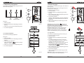
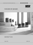
8.3 Cleaning daily
1
1
8.3.1 Cleaning the brewer unit
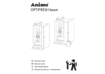
8.3.3 Cleaning the mixer unit
The brewer is in constant contact with coffee. After
some time, a deposit of coffee oils, coffee particles
and minerals from the water forms on the brewer's
permanent lter. This will reduce the permeability of the
lter and therefore increase the chances of the brewer
section overowing.
The mixer casing is in regular contact with the product
and must therefore be cleaned thoroughly and regularly.
During the cleaning procedure, the brewer is lled with
hot water. After a soaking period, the brewer is rinsed 3
times with hot water.
Requirements:
- Collection tray of at least 1.5 litres.
The mixers are rinsed with hot water 3 x during the
cleaning procedure.
Duration: approx. 1 min. (rinsing water approx. 800 ml).
2
For cleaning the mixer(s);
Duration: approx. 3 min. (rinsing water approx. 800 ml).
Requirements:
- Collection tray of at least 1.5 litres.
2
1. Open the door of the machine and press the mixer
cleaning button (g. 45-1).
2. Close the door and position the service pin (see
chapter 8.1) so that the door can remain open.
In order to clean the brewer:
1. Open the machine door and press the brewer
cleaning button (g. 43-1).
3. Follow the instructions shown on the display
(g. 45-3) and use the X and V buttons on the
operating panel (g. 45-2).
2. Close the door or position the service pin (see
chapter 8.1) so that the door can remain open.
3. Follow the instructions shown by the display
(g. 43-3) and use the X and V buttons on the
operating panel (g. 43-2).
Stopping the cleaning cycle?
3
Stopping the cleaning cycle?
The start of the brewer cleaning procedure can be
cancelled with the X button or by the C button.
Increasing the boiler temperature and soaking the
brewer can be skipped with the X button or by the
C button.
The rinsing progress (3x) can be interrupted with the
X button or by the C button.
The start of the mixer cleaning procedure can be
cancelled with the X button or by the C button.
Min 1,5 L
Increasing the boiler temperature and soaking the
brewer can be skipped with the X button or by the
C button.
oANEB aFBbBF
^FBEE BNPBF
The rinsing process can be interrupted with the
X button or by the C button.
^DVOB O?NPVANBF
^FBEE BNPBF
`?ADBF PBCI
ANOFBVEBE
Min 1,5 L
3
^DVOB O?NPVANBF
^FBEE BNPBF
TgmG
`?ADBF PBCI
ANOFBVEBE
oANEB aFBbBF
M?V>ANR pGG EBO;
8.3.2 Emptying and cleaning the waste bin
Empty the waste bin every time you
have lled the fresh brew canister.
Tip: use a well-tting bin liner (g. 44)
in order to empty and clean the waste
bin quickly!
oANEB CAqBF
^FBEE BNPBF
oANEB aFBbBF
oANEB CAqBF
pq oANEB
oANEB aFBbBF
pq oANEB
oANEB CAqBF
oBVfhr
TgmG
oANEB aFBbBF
oBVfhr
Fig. 44
78
Fig. 43
12/2009 Rev. 0.2
Fig. 45
12/2009 Rev. 0.2
79
8.4 Weekly cleaning
1
1
8.4.1 Cleaning the brewer lter / brewer chamber
8.4.2 Brewer lter cleaning
2
Carry out before the daily cleaning.
Duration: approx. 5 min.
Requirements:
- Permanent lter (cleaned) (Art. No. 03488)
- Filter disassembly tool
(Art. No. 03343)
1. Open the door of the machine and press the open/
close brewer button. The brewer will turn into the
'open' position.
Close the door or position the service pin (see
chapter 8.1) so that the door can remain open.
2. Remove the brewer chamber and coffee outlet.
3. Point the lter disassembly tool up all the way via
the brewer outlet.
4. Push the far end of the tool rmly against the
backside of the permanent lter until it clicks out
of the cylinder.
Clean permanent lter; see next chapter!
4
Remove dirty
filter
‘cl
i
ck
’
5
6
8 -12 hour
3
1. Make a solution with 1 part brewer lter cleaner
and 4 parts lukewarm water.
2. Soak the brewer lter for approx. 8-12 hours
(overnight) in the brewer lter cleaner.
3. Rinse the brewer lter thoroughly over the entire
surface.
Fig. 47
ck
’
7
The machine can indicate that the brewer lter needs
replacement.
If the display shows Renew brewer lter (g. 48),
both lters made 20.000 cups of coffee and must be
replaced as a precaution.
1. Follow the instructions of chapter 8.4.1 for replacing
the lter screen.
2. Reset the display after placing the new permanent
lter. Go to 1.5 Permanent lter of the operator
menu and reset the counter.
Art. No. permanent lter 03488
oBNBb `FBbBF @ADPBF
XV>B h?KF On?AOB
Fig. 48
Fig. 46a
80
2
8.4.3 Replacing the brewer lter
Clean!
8
8. Press the brewer open/close button. The brewer
returns to its initial position. The machine is ready
for use again.
* Use a normal detergent.
In case of persistent stains, use our tried and tested
coffee fur remover!
1: 4
Position cleaned
or new filter
‘cl
i
5. Place a clean (or new) permanent lter into the
brewer cylinder. Ensure that the protruding section
points backwards. Press the lter until it clicks into
the cylinder.
6. Clean*/rinse the brewer chamber and coffee outlet
thoroughly.
7. Place the brewer chamber and coffee outlet back
on the brewer.
CAUTION: the brewer can be severely
damaged if the brewer section is not well
SECURED when returning it to the machine.
Make sure that the wiper is always placed
BETWEEN both arms!
3
The brewer is in constant contact with coffee. After
some time, a deposit of coffee oils, coffee particles
and minerals from the water forms on the brewer's
permanent lter. This will reduce the permeability of the
lter and therefore increase the chances of the brewer
chamber overowing.
The brewer lter must be kept in the best
possible condition by carrying out the
following cleaning procedure.
First carry out Chapter 8.4.1 Cleaning the brewer lter /
brewer chamber!
Requirements:
- Collection tray with the size of the permanent lter
- Brewer lter cleaner
(Art. No. 00002)
- Brewer lter *
(Art. No. 03488)
- Filter disassembly tool
(Art. No. 03343)
* supplied with the machine
Fig. 46
12/2009 Rev. 0.2
12/2009 Rev. 0.2
81
8.4.6 Cleaning the mixer unit
8.4.4 Cleaning the coffee grinder
Weekly clean the coffee outlet by removing it from the
grinder.
1
The mixer casing is in regular contact with the product
and must therefore be cleaned thoroughly and regularly.
The grinder can only be cleaned by your dealer. This is
combined with half yearly maintenance.
If the machine is used very frequently, carry out this
cleaning procedure up to a few times a week!
Duration: approx. 5 min.
Requirements:
- Normal detergent / coffee deposit remover
- Rinsing facility
- Tea towel
- Hygiene set (for quick cleaning)
Cleaning mixer(s) (g. 50):
1. Remove the tubes between the mixer(s) and the
outlet. Remove the ingredient canisters from the
device (turn the dispensing elements up so that no
ingredients fall out).
8.4.5 Removing the entire brewer
The brewer can be entirely removed for thorough
cleaning.
1
Removing the brewer (g. 49):
2. Turn the green mounting ring to the right and
remove the mixer casing by pulling it towards you.
1. Open the door of the machine and press the open/
close brewer button. The brewer will turn into the
'open' position.
3. Pull the mixer fan towards you to remove it from the
mixer axis and remove the green mounting ring.
Close the door or position the service pin (see
chapter 8.1) so that the door can remain open.
Then remove the service pin so that the brewer can
be safely removed.
3
4. Clean the removed parts in warm water with a
normal detergent.
2
4
5. Fit the parts in the opposite order.
3
CAUTION: ensure that the arrow on the
mixer fan points towards the at side of the
axis and push the mixer fan over the axis
until you hear a clear 'click' (don't push it too
far down!).
2. Flip up the hot water machine arm.
3. Remove the coffee outlet from the brewer.
2
4
4. Remove the waste bin.
5
Clean
& dry !
6
5. Remove the water connection.
6. First pull the bottom section of the brewer towards
you to release it from the drive mechanism.
7. Lift the brewer from the suspension bracket.
8. The brewer can now be thoroughly cleaned.
9. Position the parts back into the machine in
reverse order. Caution: rst secure the brewer into
the suspension bracket and then press the bottom
section back into the drive mechanism. Do not
forget to reconnect the water supply (5)!
10. Press the open/close brewer button. The brewer will
return to its initial position. The machine is ready for
use again.
Fig. 50a
5
7
6. Place the mixer case back onto the mixer. Turn the
green mounting ring to the left.
7. Secure the tubes between the mixer(s) and the
outlet. Place the canisters back and turn the
dispensing elements back into the correct position.
6
Switch the device back on and try a few test drinks
to check the correct operation.
7
*
Fig. 49
82
12/2009 Rev. 0.2
Use a normal detergent.
In case of persistent stains, use our tried and tested
coffee fur remover!
12/2009 Rev. 0.2
83
Fig. 50
8.5 Monthly cleaning
1
8.5.1. Cleaning the brewer unit
8.5.2 Cleaning the mixer extraction lter
The brewer is in constant contact with coffee. After
some time, a deposit of coffee oils, coffee particles and
minerals from the water forms on the brewer's permanent lter.
First carry out chapter 8.4.5 Cleaning the mixer unit
(weekly)!
The brewer lter must be kept in the best
possible condition by carrying out the
following cleaning procedure.
If the machine is used very frequently, carry out this
cleaning procedure every week!
2
During the cleaning procedure, the brewer is lled with
hot water. After a soaking period, the brewer is rinsed 3
times with hot water.
10
.
gr
Duration: approx. 2 min.
Requirements:
- Normal detergent / coffee fur remover
- Tea towel
- Hygiene set (for quick cleaning)
Duration: approx. 8 min. (rinsing water approx. 800 ml).
Requirements:
- Collection tray of at least 1.5 litres.
- Sachet of coffee deposit remover
1. Turn the green mounting ring right and remove the
mixer case from the mixer by pulling it towards you.
3
3. Remove the top plate and the blue lter.
5. Place the lter back in its position and reapply the
top plate.
Attention: if the brewer has been cleaned
with detergent, make sure you immediately
carry out chapter 8.4.1 Cleaning the brewer
chamber / brewer lter.
5. Take two coffees to lubricate the brewer cylinder
again.
6. Put the extraction lter(s) back in place.
The start of the brewer cleaning procedure can be
cancelled with the X button or by the C button.
Increasing the boiler temperature and soaking the
brewer can be skipped with the X button or by the
C button.
The rinsing progress (3x) can be interrupted with the
X button or by the C button.
Min 1,5 L
4
8. Secure the tubes between the mixer(s) and the
outlet.
6
Turn the device back on and try a few test drinks to
check correct operation.
oANEB aFBbBF
^FBEE BNPBF
^DVOB O?NPVANBF
^FBEE BNPBF
*
TgmG
Use a normal detergent.
In case of very persistent stains use our coffee
fur remover!
7
oANEB aFBbBF
M?V>ANR pGG EBO;
oANEB aFBbBF
Fig. 52
oANEB aFBbBF
pq oANEB
oANEB aFBbBF
oBVfhr
84
5
Clean
& dry !
7. Place the mixer case back on to the mixer. Turn the
green mounting ring to the left.
`?ADBF PBCI
ANOFBVEBE
Stopping the cleaning cycle?
4
4. Clean* and dry the lter or use a clean lter from the
hygiene set.
2. Fill the brewer section (g. 51-2) in advance with 1
sachet /1 tea spoon of coffee deposit remover.
4. Follow the instructions shown by the display (g.
51-3) and use the X and V buttons on the operating
panel (g. 51-2).
3
2. Pull the extraction lter(s) from the machine.
1. Open the machine door and press the brewer
cleaning button (g. 51-1).
3. Close the door or position the service pin (see
chapter 8.1) so that the door can remain open.
2
Cleaning brewer lter (g. 52):
(Art.No. 49009)
In order to clean the brewer:
1
Fig. 51
12/2009 Rev. 0.2
12/2009 Rev. 0.2
85
8.6 Cleaning the canister(s)
8.7 Other maintenance
8.6.1 Instant canister(s)
Casing
Daily: Clean the dispensing opening (g. 53-1) and the
dispensing element (g. 53-2) with a dry dusting brush.
Weekly: Empty and clean the ingredient canister(s) with
a dry dusting brush. Remove any caked residue.
Clean and dry the stainless steel exterior with a clean
damp cloth every day.
1
2
Do not use any abrasives as the can cause scratches
or dull areas.
Instant
Fig. 53
Do not use chlorine or chlorinated detergent as
this will damage the stainless steel.
Monthly: Empty and wash the ingredient canister(s) with
a mild detergent.
The canisters are dishwasher-safe.
Instant
If necessary the transport auger (g. 54-2) can be
removed by unscrewing the front (g. 54-3) and back
swivel (g. 54-1). The entire auger can then be
removed.
Pay attention when tting the dispensing
opening of the instant canister (g. 54-4). The
opening must be pointed upwards.
Drip tray and cup tray
1
2
3
4
Make sure you keep every transport augers with its
own canister during reassembly.
The drip tray and grid should be emptied, cleaned with
a clean damp cloth and dried every day.
Clean the drip tray and grid in hot water every week.
The drip tray has a safety feature with an electronic sensor that switches the device off when
the maximum level is exceeded.
Fig. 54
Ensure the canisters are COMPLETELY dry before
relling them.
Interior
8.6.2 Bean canister
The inside of the door and the bottom plate must be
cleaned with a damp cloth and dried every day.
Monthly bean canister empty and wash with a mild
detergent.
Empty and rinse the waste bin every day.
The beans canister must not be washed in the
dishwasher.
1
2
Use a well-tting bin liner to
make emptying and cleaning of
the waste bin easier!
1. Slide down the bean stopper (g 55-1).
2. Lift the canister from the coffee grinder and empty it.
(Fig. 55-2).
3. Clean the canister and lid with a mild detergent.
Fig. 56a
4. Before placing the canister back dry it VERY well!
5. Place the canister back on the coffee grinder (Fig.
55-3)
Canister compartment
6. Slide up the bean stopper so the canister will be
xated again (Fig. 55-4).
The canister compartment should be cleaned with a
clean damp cloth and dried every week.
7. Fill the canister with fresh coffee beans.
3
4
Fig. 55
Fig. 56
86
12/2009 Rev. 0.2
12/2009 Rev. 0.2
87
10. DRY BOIL PROTECTION
WARNING
The device has a dry boil protection that is accessible
from the outside. It is located at the back of the device
(g. 58). The dry boil protection turns off the heating
element if the temperature is too high. This is usually
caused by not descaling the device in time. If the
appliance is no longer heating the water, please do the
following:
1. Allow the device to cool down.
2. Remove the black protective knob (g. 58-2).
3. Now press the visible button (g. 58-1) and push
the protective knob back into place.
If the safety device turned off the machine and the
message [Descale / lter] is visible when restarting the
machine, then have the machine descaled. See chapter
9. Setting the service moment.
In order to descale the water reservoir, the device
must be opened. This will expose live parts of the
machine, which can be touched easily. This can lead
to highly dangerous situations!
WARNING
The device must not be submerged or hosed down.
Always stay with the device during maintenance
work.
9. SETTING THE SERVICE MOMENT
During the installation of the device, your service engineer set a time for the device to be serviced.
Please do the following before transporting or putting
the device in storage.
eBEOVDB l @ADPBF
XV>B h?KF On?AOB
The message indicates that the device must be descaled. If a water lter was tted (advised), this is also
an indication that the lter must be replaced.
Fig. 57
For safety reasons, users are not advised to descale
the machine and/or replace the lter. We advise you
to have an authorised service engineer descale and
maintain the device.
Water hardness table
Hardness
°F
°C
mmol/l
mgCaCo3/l
Limescale
Indicator ...cups
Very hard
18-30
32-55
11-18
3,2-5,3
321- 536
5000
Hard
12-18
22-32
7-18
2,2-3,2
214-321
8500
Average
8-12
15-22
5-7
1,4-2,2
268-214
12.500*
Soft
4-8
7-15
2-5
0,7-1,4
72-268
20.500
Very soft
0-4
0-7
0-2
0- 0,7
0-72
0 = off
1. Carry out the brewer and mixer unit cleaning pro
gramme.
2. Clean the ingredient canister(s), mixer system,
leaking tray and casing as described in chapter
8. Maintenance.
3. Switch off the device and remove the plug from the
wall socket.
4. Close the water supply tap and disconnect the
water connection tube.
5. Drain the water reservoir (approx. 3 litres) by using
the draining tube (Fig. 59-1).
6. Put the parts mentioned in point 5 back in their
place.
7. The device is now ready for transport.
8. Before reinstalling the device, please ensure chapter
3. Installation is followed.
Table 3
88
2
11. TRANSPORT / STORAGE
When this message appears, you can continue to use
the device as usual.
°D
1
Fig. 58
The dispensed drinks are counted during use.
If the set time for service is reached, the display
shows the following message: Descale / lter
(g. 57).
Water
Quality
Reset
12/2009 Rev. 0.2
12/2009 Rev. 0.2
89
1
~
Volt
Fig. 59
12. TROUBLESHOOTING
Display
messages
and errors
Out of order
Boiler lling
Display
messages
and errors
Possible cause
Action
When used for the rst time: boiler
is still empty and is being lled.
No action required. When boiler achieves
the appropriate level, the display will show
'Boiler is heating up'.
Possible cause
Action
E7 BM/MM1 error
Brewer overload.
The brewer is stuck or tted incorrectly.
Remove the brewer from the machine. See
chapter 8.7.2 Remove the entire brewer.
Switch the device off and on again.
E8 Mixer 2 error
Mixer 2 overload.
Mixer 2 is unclean or incorrectly tted.
Clean and/or check whether the rotor can
run freely.
Switch the device off and on again.
During use: boiler is not lling up
or is lling up too slowly. After 60 sec.
the display will show 'E3 Level error'.
Check the water pressure, turn the water
supply tap completely open, check the
connection tube for any kinks.
Out of order
Boiler heating
The boiler temperature is (temporarily) too low because too much
water has been used.
Once the temperature is ne, the message
automatically disappears and the drink
selection buttons are enabled again.
E9 Mixer 3 error
Mixer 3 overload.
Mixer 3 is unclean or incorrectly tted.
Clean and/or check whether the rotor can
run freely.
Switch the device off and on again.
Out of order
Drip tray full
Drip tray full.
Once the drip tray is emptied, the message
automatically disappears and the drink
selection buttons are enabled again.
E10 Valve error
Valve overload.
Call your dealer or service engineer.
Out of order
Waste bin full
The maximum number of cups of
coffee tting into the waste bin has
been reached.
Empty waste bin. The cup counter is automatically reset as the waste bin is put back
in its place.
E11 Ingr. m. error
Ingredient prime mover overload.
Out of order
Waste bin is missing
Waste bin is not being detected.
Check the waste bin.
The prime mover of one of the canisters is
not running smoothly.
Empty and thoroughly clean the canister(s).
See chapter 8.9 Cleaning the canisters.
Switch the device off and on again.
Out of order
Door open
For safety reasons, the machine
is switched off when the door is
opened.
The machine can be switched on with
the door open by using the door pin (see
chapter 8).
E12 Fan error
Fan overload.
Call your dealer or service engineer.
E13 Mixer error
Mixer group overload.
The machine is on stand-by.
This function can be set manually (see
chapter 5.2-A) or automatically (see chapter 6.1 menu item 1.2 Timer settings).
Clean and/or check whether the rotor can
run freely.
Switch the device off and on again.
Ingredient prime mover group
overload.
The prime mover of one of the canisters is
not running smoothly.
Empty and thoroughly clean the canister(s).
See chapter 8.9 Cleaning the canisters.
Switch the device off and on again.
Valve group or fan overload.
Call your dealer or service engineer.
Out of order
E16 Level error
Boiler level suddenly much to low.
Call your dealer or service engineer.
Out of order
E17 MDB error
There is no communication
between machine and payment
system
Switch the device off and on again.
Call your dealer or service engineer.
Out of order
Stand-by
E1 Level error
Sensor level problem.
Call your dealer or service engineer.
Boiler is lling up to slowly.
There is no water pressure or the
water tank (standalone setup) is
empty.
Check the water pressure, turn the water
supply tap completely open, check the
connection tube for any kinks. Turn the
device off and on again.
E3 Level error
Boiler is not lling up.
Check the water pressure, turn the water
supply tap completely open, check the
connection tube for any kinks. Turn the
device off and on again.
E4 Brewer error.
Brewer was not started from its
initial position.
Check whether the brewer was correctly
placed into its bracket. Turn the device off
and on again.
E5 Brewer error
Brewer was not returned to its
initial position.
Check the brewer.
E6 Boiler temp
Temperature sensor problem.
Call your dealer or service engineer.
E2 Level error
90
12/2009 Rev. 0.2
E14 Exit error
12/2009 Rev. 0.2
91
13. ORDERING CONSUMABLES AND ACCESSORIES
Malfunction
Possible cause
Action
Fuses (distribution board).
Check fuses.
Main switch (distribution
board).
Check main switch.
The plug and lead.
Check main cable.
The device is in standby.
Switch off stand-by modus.
Fresh brew
The device does not
work.
The device does not
respond.
Instant
Decafé
Canister (almost) empty.
(Re)ll ingredient canister.
Incorrectly canister position.
Check position.
Canister outlet blocked.
Clean outlet.
Canister auger is loose or
damp.
Check or clean auger.
Canister distributor does not
work.
Check distributor.
Wrong ingredient
Check if the right ingredient is used.
Ingredient is solidied (caked)
Replace ingredient
Mixer(s) not cleaned/rinsed
Run rinsing programme
07975
03258
03284
03259
03260
Brewer lter
03343
03488
03257
03255
07974
08419
03254
03253
There are complaints
about the products taste.
Ingredient expired
Replace ingredient
Boiler temperature too low
Please warn your supplier
03326
03256
1 KG 100x10gr.
Brewer cleaner
07976
0,92 L.
Brewer lter cleaner
OptiFresh 2-3
OptiFresh 4
00008 49009
00002
11831
11832
Check the ventilation system and
replace the ingredient
Damp ingredient
92
12/2009 Rev. 0.2
12/2009 Rev. 0.2
93
Afmetingen / Dimensions / Abmessungen / Dimensions
Afmetingen / Dimensions / Abmessungen / Dimensions
OptiFresh 1, 2 & 3 bean
OptiFresh 4 bean
589
483
483
589
527
483
527
483
160
920
390
36
390
36
589
272
98
89
839
123
214
123
214
880
821
800
880
821
800
160
60 ~
131
187
Volt
60 ~
131
187
Volt
(OptiFresh 3)
186
12/2009 Rev. 0.2
12/2009 Rev. 0.2
187
Afmetingen / Dimensions / Abmessungen / Dimensions
Afmetingen / Dimensions / Abmessungen / Dimensions
OptiFresh 1, 2, 3 bean Muntmechannisme / Coin system / Münzprüfer System / Système monnayeur
OptiFresh 1, 2, 3 bean Muntwisselaar / Coin changer / Münzwechsler / Monnayeurs-rendeurs
484
749
402
589
402
472
589
527
483
160
527
483
160
123
800
880
60
91
187
~
Volt
36
36
214
214
821
213
123
800
821
880
201
OptiFresh 4 bean Muntmechannisme / Coin system / Münzprüfer System / Système monnayeur
Volt
OptiFresh 4 bean Muntwisselaar / Coin changer / Münzwechsler / Monnayeurs-rendeurs
589
483
830
483
565
589
553
60 ~
91
187
527
483
527
160
483
160
36
188
60
131
187
36
214
123
800
880
123
214
821
213
800
821
880
201
~
Volt
12/2009 Rev. 0.2
60 ~
131
187
Volt
12/2009 Rev. 0.2
189
Afmetingen / Dimensions / Abmessungen / Dimensions
Onderkast / Base cabinet / Unterschrank / Table support
art.nr. 65070
925
670
962
521
485
625
505
Met afvalbak / With waste bin / Mit Abfallbehälter / Avec trappe
art.nr. 65060
925
670
962
521
485
625
505
Animo B.V. Headofce
Dr. A.F. Philipsweg 47
P.O. Box 71
9400 AB Assen
The Netherlands
Tel. no. +31 (0)592 376376
Fax no. +31 (0)592 341751
E-mail: [email protected]
Internet: http://www.animo.eu
190
12/2009 Rev. 0.2
Rev. 0.2 12/2009 Art.nr 09751