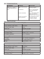
1
Models: PSI-1500, and PSI-2000
owner’s manual
The recommended source of power is a 12-volt deep-cycle
battery due to their high reserve capacity. Automotive batteries are recommended for only a short period of time of
an hour or less
00-99-000902/0908
IMPORTANT: READ AND SAVE THIS SAFETY AND INSTRUCTION MANUAL
1.
IMPORTANT SAFETY INSTRUCTIONS
1.1
Place the power inverter on a flat surface.
1.2
Keep the inverter well ventilated. Make sure there are several inches
of clearance around the top and sides and do not block the slots of the
inverter.
1.3
Make sure the inverter is not close to any potential source of flammable
fumes, gases or clothing.
1.4
Do not place the inverter in areas such as battery compartments or engine
compartments where fumes or gases may accumulate.
1.5
Keep the inverter dry.
1.6
DO NOT allow the inverter to come into contact with rain or snow.
1.7
DO NOT operate the inverter if you, the inverter, the device being operated or any other surfaces that may come into contact with any power
source are wet. Water and many other liquids can conduct electricity,
which may lead to serious injury or death.
1.8
Do not place the inverter on or near heating vents, radiators or other
sources of heat or flammable materials.
1.9
Do not place the inverter in direct sunlight. The ideal air temperature for
operation is between 50° and 80°F.
1.10 Only connect the power inverter to a 12-volt battery or power supply. Do
not attempt to connect the inverter to any other power source, including
an AC power source. Connecting to a 6-volt or 16-volt battery will cause
damage to the inverter.
1.11 Make sure the AC plug connection is tight.
1.12 Do not modify the AC receptacle in any way.
1.13 Do not try extending or modifying the 12-volt power cord supplied with
your inverter. Make sure the cord connections are tight.
1.14 Incorrect operation of your inverter may result in damage and personal
injury.
WARNING: The inverter output is 110V AC and can shock or electrocute
the same as any ordinary household AC wall outlet.
1.15 Do not open – No user serviceable parts inside.
WARNING: Pursuant to California Proposition 65, this product contains
chemicals known to the State of California to cause cancer and birth defects or other reproductive harm.
•3•
2.
INVERTER FEATURES
2.1
ON/OFF Rocker Switch – Turns the inverter ON and OFF.
2.2
LED Indicator Light – (Green = power ON, Red = Overload/Interruption
in power.)
2.3
12-Volt Power Cord – One pair.
2.4
110V AC Outlet – Two GFCI.
2.5
High-Speed Cooling Fan(s) – Keeps the inverter cool. The speed of the
fan is faster as the load increases. The fan does not run when the inverter
is turned OFF.
2.6
Analog Output Power Display – Shows 110V AC continuous power
consumed. Five lights indicate half of the continuous output power and
10 lights indicate full continuous power consumption. When the inverter is
OFF, the lights do not illuminate.
2.7
Positive Battery Cable Terminal (Red) – Accepts Positive connector
cable.
2.8
Negative Battery Cable Terminal (Black) – Accepts Negative connector
cable.
2.9
Ground Terminal – Grounds inverter to reduce electrical shock.
2.10 Thermal Protection – When the inverter case becomes hot (exceeds
145° F) the inverter shuts down until it cools off and then automatically
restarts.
2.11 Surge Protection – When the power input from the vehicle’s battery
exceeds 15-volts, the inverter shuts down. Once the voltage drops down
to less than 14, it automatically restarts.
2.12 Low-Battery Protection – When the power input from the vehicle’s battery drops to approximately 10-volts, the inverter shuts down.
3.
FASTENING THE INVERTER TO A FLAT SURFACE
For your convenience, the inverter can be fastened to a flat surface, horizontally or vertically. The area where the inverter is to be fastened must be
dry, well ventilated and away from any combustible material or fumes.
3.1
Turn off and disconnect the inverter.
3.2
Place the back of the inverter with the mounting bracket against a secure,
flat surface.
3.3
Attach the inverter to the flat surface using corrosion resistant screws.
4.
GROUNDING THE INVERTER
To avoid electrical shock, it is necessary to ground the inverter as well as
the device powering it. The inverter should be grounded using a #8 AWG
copper wire (not included).
NOTE: Do not turn on the inverter or the power source until the inverter
•1•
and the power source are grounded.
To ground the inverter:
4.1
Turn off and disconnect the inverter.
4.2
Locate the chassis ground screw below the negative terminal on the left
side of the inverter.
4.3
Remove the outer hex nut and loosen the second hex nut.
4.4
Strip the insulation of the #8 AWG copper wire back 1.5” and wrap the
bare end of the wire around the ground screw between the two washers.
4.5
While holding the wire in place, tighten the hex nut securely. Then, replace
the other hex nut and tighten it securely.
4.6
Attach the other end of the wire to a properly grounded location:
VEHICLE: Connect to the chassis, unpainted frame part, or engine block
of the vehicle.
BOAT: Connect to the boat grounding system.
FIXED LOCATION: Connect to a ground rod or other appropriately rated
ground.
5.
BEFORE USING YOUR POWER INVERTER
IMPORTANT: Install and use this inverter in NEGATIVE GROUND applications only.
When you turn on a device or a tool that runs on a motor, the device goes
through two stages:
1. Start Up – Requiring an initial surge of power (commonly known as the
“starting or peak load”).
2. Continuous Operation – Power consumption drops (commonly known
as the “continuous load”).
The wattage (WATTS) or amperes (AMPS) are normally found stamped or
printed on most devices and equipment, or in the owner’s manual. Otherwise, contact the manufacturer to find out whether the device you want to
use is compatible with a modified sine wave.
To calculate the wattage: Wattage = AMPS x 110 (AC Voltage).
To calculate the starting load: Starting Load = 2 x WATTS. In general,
the start up load of the device or power tool determines whether your
inverter has the capability to power it.
To calculate the continuous load: Continuous Load = AMPS x 110 (AC
Voltage).
Attention: Always run a test to establish whether the inverter will operate a particular piece of equipment or device. In the event of a power
overload, the inverter is designed to automatically shut down. This safety
feature prevents damaging the inverter while testing devices and equip•2•
ment within the wattage range of the inverter.
If a device does not operate properly when first connected to the inverter,
turn the inverter rocker switch ON (I), OFF (O), and ON (I) again in quick
succession. If this procedure is not successful, it is likely that the inverter
does not have the required capacity to operate the device in question.
6.
CONNECTING INVERTER CABLES
The inverter and power source must be in the OFF mode.
IMPORTANT: Make sure you connect the inverter to a 12-volt power supply only.
6.1
INVERTER CONNECTION
1. Locate the Positive and Negative plastic terminals located on the left
side of the inverter. Using a standard (flathead) screwdriver, unscrew
the positive (red) and negative (black) terminal screws just enough to
be able to insert the bare end of the connector cables.
2. Insert the bare end of the positive (red) cable into the positive (red)
terminal. Insert the bare end of the negative (black) cable into the
negative (black) terminal. Tighten each terminal screw so that the cable
cannot come loose.
6.2
CONNECTING INVERTER CABLES TO 12V BATTERY OR 12V POWER
SOURCE:
1. Keep hands, hair, clothing and jewelry clear of battery terminals.
2. Wear eye protection and clothing protection.
3. Connect the negative (black) inverter terminal cable to the power
source negative (-) or battery terminal. Make sure the connection is
secure.
4. Connect the positive (red) inverter terminal cable to the power source
positive (+) or battery terminal. Make sure the connection is secure.
5. To disconnect the inverter, reverse the above steps.
NOTE: The internal speaker may beep when the inverter is being connected to or disconnected from the 12-volt power source.
ATTENTION: Failure to make the correct connections will result in blown
fuses and permanent damage to the inverter.
7.
USING THE GFCI OUTLET
The inverter includes two GFCI (Ground Fault Circuit Interrupter) outlets
located on the right side of the inverter. The purpose of a GFCI outlet is
to quickly stop the flow of electricity in the event a ground fault occurs on
the device plugged into the inverter’s GFCI outlet. Use only a 3-prong
grounded plug when using the GFCI outlets.
The GFCI outlets provide auxiliary power to 110V AC devices that require
less than 15-amps; and auxiliary power to 120V AC devices that require
•3•
less than 15 amp. If using both GFCI outlets at the same time, the amperage cannot exceed a total of 15 amps for both devices combined.
The GFCI must be tested before each use. To test:
1. Connect the inverter (see CONNECTING INVERTER CABLES section).
2. Turn the inverter on.
3. Push the “Reset” button located on the GFCI receptacle first to assure
normal GFCI operation.
4. Plug a nightlight (with an ON/OFF switch) or other device (such as a
lamp) into the GFCI receptacle and turn the device ON.
5. Push the “Test” button located on the GFCI receptacle. The nightlight
(or other device) should turn OFF.
6. Push the “Reset” button and the light (or other device) should turn ON
again.
NOTE: If the light (or other device) remains ON when the “Test” button is
pushed, the GFCI is not working properly and should not be used. Call
Customer Service (1-800-621-5485).
8.
OPERATING INSTRUCTIONS
8.1
Connect the inverter (see the CONNECTING INVERTER CABLES section.
8.2
Switch the inverter switch to the ON (I) position.
8.3
The LED indicator light should glow GREEN verifying the inverter is receiving power.
8.4
Turn the inverter rocker switch to the OFF (O) position. (The GREEN LED
power indicator light may flash briefly and/or the internal speaker may
beep. This is normal.)
8.5
Make sure that the device to be operated is turned OFF.
8.6
Plug the device into the inverter AC outlet.
8.7
Turn the inverter on.
8.8
Turn the device on.
8.9
To disconnect, reverse the above procedure.
NOTE: Only power one device at a time to avoid a power surge and overloading the inverter. The surge load of each device should not exceed the
inverter’s Continuous Operation wattage rate.
IMPORTANT: If you are using the power inverter to operate a battery
charger, monitor the temperature of the battery charger for about 10 minutes. If the battery charger becomes abnormally warm, disconnect it from
the inverter immediately.
•4•
NOTE: You can use an extension cord from the inverter to the device
without significantly decreasing the power being generated by the inverter.
For best operating results, the extension cord should be no longer than 50
feet.
9.
Using the Inverter to Operate a TV or Audio Device:
The inverter is shielded and filtered to minimize signal interference.
Despite this, some interference may occur with your television picture,
especially with weak signals. The following are suggestions to improve
reception.
9.1
Make sure that the television antenna produces a clear signal under
normal operating conditions (i.e. at home plugged into a standard 110-volt
AC wall outlet). Also, ensure that the antenna cable is adequately shielded
and of good quality.
9.2
Try altering the position of the inverter, antenna cables, and television
power cord. Plug in an extension cord from the inverter to the TV to isolate
its power cord and antenna cables from the 12-volt power source.
9.3
Try coiling the television power cord and the input cables running from the
12-volt power source to the inverter.
9.4
Affix one or several “Ferrite Data Line Filters” to the television power
cord. Ferrite Data Line Filters can be purchased at most electronic supply
stores.
9.5
Try grounding the inverter with an 18 AWG (minimum) wire.
NOTE: You may hear a “buzzing” sound being emitted from your sound
systems when operated with the inverter. This is due to ineffective filters in
the sound system’s power supply. Unfortunately, this problem can only be
resolved by purchasing a sound system with a higher quality power supply
or higher quality filter.
10. POWER SOURCE
Your average automobile or marine battery at full charge will provide an
ample power supply to the inverter for approximately 30 to 60 minutes
when the engine is off. The actual length of time the inverter will function
depends on the age and condition of the battery and the power demand
being placed by the device being operated with the inverter.
If you decide to use the inverter while the engine is off, turn OFF the
device plugged into the inverter before starting the engine. To maintain
battery power, start the engine every 30 to 60 minutes and let it run for approximately 10 minutes to recharge the battery.
Although it is not necessary to disconnect the inverter when turning over
the engine, it may briefly cease to operate as the battery voltage decreases. While the inverter draws very low amperage when not in use, it should
be unplugged to avoid battery drain.
•5•
11.
HOW DO POWER INVERTERS WORK?
There are two stages involved in transforming 12-volt DC (battery) power
into 110-volt AC (household voltage):
STAGE 1: The power inverter uses a DC to DC transformer to increase
the 12-volt DC input voltage from the power source to 145-volt DC.
STAGE 2: The inverter then converts the 145-volt DC into 110-volts AC
(household voltage) using advanced MOSFET transistors in a full bridge
configuration. A “modified sine wave” waveform is generated by this conversion.
12. LED INDICATORS AND SHUTDOWN PROTECTION
The GREEN LED lights automatically when plugged into a 12-volt DC
source and turned on. The RED LED lights, the alarm sounds, and the
inverter automatically turns itself off under the following conditions:
• When the power input from the vehicle’s battery drops to approximately
10-volts, low battery shutdown occurs. (When the power input drops to
10.5-volts, an alarm will sound for an extended period.) Solution: Recharge or Replace the battery.
• When the power input from the vehicle’s battery exceeds 15-volts, high
voltage overload protection occurs. Solution: Reduce the voltage range to
between 12-volts and 14-volts.
• The continuous load demand from the equipment or device being operated exceeds the continuous load rating of the inverter being used. Solution: Use a higher capacity inverter or lower rated device.
• The case temperature becomes hot (exceeds 145°F). Your inverter is
fitted with a cooling fan that runs as needed while the inverter is operating. If the cooling fan is unable to maintain a cool enough temperature for
safe operation, the inverter will automatically shutdown. Solution: Allow
the inverter to cool. Do not block the cooling fan, cooling slots or air flow
over and through the inverter. Reduce the load on the inverter to the
continuous rated output.
RESET: To reset after shutdown occurs, turn the inverter rocker switch to
the OFF (O) position. Check the source of the problem and correct. Turn
the inverter switch to the ON (I) position.
13. IF THE INVERTER FUSE BLOWS
Your power inverter is fitted with a fuse, which should not have to be replaced under normal operating conditions. A blown fuse is usually caused
by reverse polarity or a short circuit within the device or equipment being
operated.
If the fuse does blow, take the inverter to a qualified technician for repair.
•6•
14. troubleshooting
PROBLEM
REASON
SOLUTION
Red LED is on, audible
alarm is on, and/or
inverter does not function.
Poor contact at terminals.
Check the connections
at power supply.
Fuse Blown.
See “IF THE INVERTER FUSE BLOWS”
section.
Inverter shutdown.
See “LED INDICATOR
AND SHUTDOWN
PROTECTION” section.
Inverter may not be
working properly.
See Warranty and call
Customer Service
(1-800-621-5485)
15. SPECIFICATIONS
Model: PSI-1500
Maximum Continuous Power
1500 Watts
Surge Capability (Peak Power)
3000 Watts
No Load Current Draw
<0.6A
Wave Form
Modified Sine Wave
Input Voltage Range
10.5V – 15.5V DC
Output Voltage Range
110V – 125V AC
Low Battery Alarm
Audible, 10.3V – 10.6V DC
Low Battery Shutdown
9.7V – 10.3V DC
High Battery Shutdown
15.0V – 16.0V DC
Optimum Efficiency
>85%
AC Outlet
Two, 110V AC 3-Prong GFCI
Dimensions
11” L x 9.5” W x 3.75” H
Weight
Approximately 7.9 lbs.
Model: PI-2000
Maximum Continuous Power
2000 Watts
Surge Capability (Peak Power)
4000 Watts
No Load Current Draw
<0.8A
Wave Form
Modified Sine Wave
Input Voltage Range
10.5V – 15.5V DC
Output Voltage Range
110V – 125V AC
Low Battery Alarm
Audible, 10.3V – 10.6V DC
•7•
Model: PI-2000
Low Battery Shutdown
9.7V – 10.3V DC
High Battery Shutdown
15.0V – 16.0V DC
Optimum Efficiency
>85%
AC Outlet
Two, 110V AC 3-Prong GFCI
Dimensions
15.5” L x 9” W x 3.75” H
Weight
Approximately 12.25 lbs.
16. replacement parts
16.1 Fuses: Replacement fuses can be purchased at most electronic component retailers.
16.2 Battery Clamp Adapter with Cables
Part Numbers: 3899002012 (RED) 3899002013 (Black)
17.
limited warranty
SCHUMACHER ELECTRIC CORPORATION, 801 BUSINESS CENTER DRIVE, MOUNT
PROSPECT, IL 60056-2179, MAKES THIS LIMITED WARRANTY TO THE ORIGINAL RETAIL PURCHASER OF THIS PRODUCT. THIS LIMITED WARRANTY IS NOT
TRANSFERABLE OR ASSIGNABLE.
Schumacher Electric Corporation (the “Manufacturer”) warrants this Power Inverter for
two years] from the date of purchase at retail against defective material or workmanship
that may occur under normal use and care. If your unit is not free from defective material or workmanship, Manufacturers obligation under this warranty is solely to repair or
replace your product, with a new or reconditioned unit, at the option of the Manufacturer.
It is the obligation of the purchaser to forward the unit, along with mailing charges prepaid
to the Manufacturer or its authorized representatives in order for repair or replacement to
occur.
Manufacturer does not provide any warranty for any accessories used with this product
that are not manufactured by Schumacher Electric Corporation and approved for use with
this product. This Limited Warranty is void if the product is misused, subjected to careless
handling, repaired, or modified by anyone other than Manufacturer or if this unit is resold
through an unauthorized retailer.
Manufacturer makes no other warranties, including, but not limited to, express, implied or
statutory warranties, including without limitation, any implied warranty of merchantability
or implied warranty of fitness for a particular purpose. Further, Manufacturer shall not be
liable for any incidental, special or consequential damage claims incurred by purchasers, users or others associated with this product, including, but not limited to, lost profits,
revenues, anticipated sales, business opportunities, goodwill, business interruption and
any other injury or damage. Any and all such warranties, other than the limited warranty
included herein, are hereby expressly disclaimed and excluded. Some states do not allow the exclusion or limitation of incidental or consequential damages or length of implied
warranty, so the above limitations or exclusions may not apply to you. This warranty gives
you specific legal rights and it is possible you may have other rights which vary from this
warranty.
THIS LIMITED WARRANTY IS THE ONLY EXPRESS LIMITED WARRANTY AND THE
MANUFACTURER NEITHER ASSUMES OR AUTHORIZES ANYONE TO ASSUME OR
MAKE ANY OTHER OBLIGATION TOWARDS THE PRODUCT OTHER THAN THIS
WARRANTY.
WARRANTY VALIDATION: To activate this limited warranty, within 30 days of product
purchase you must either complete and return the enclosed “Warranty Card” along with
the product receipt to the Manufacturer or go online to www.batterychargers.com and fill
out the online warranty card.
Call Customer Service at: 800-621-5485 Monday - Friday, 7 a.m. to 5 p.m.
•8•
•9•