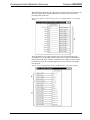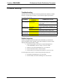
1
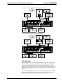
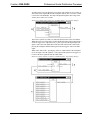
Crestron CNX-PAD8 Professional Audio Distribution Processor Contents Professional Audio Distribution Processor: CNX-PAD8 1 Description .......................................................................................................................... 1 Functional Description............................................................................................ 1 Physical Description ............................................................................................... 1 Leading Specifications ......................................................................................................... 4 Setup.................................................................................................................................... 5 Network Wiring...................................................................................................... 5 Rack Mounting....................................................................................................... 6 Hookup .................................................................................................................. 7 Identity Code.......................................................................................................... 8 SIMPL™ Windows Programming ................................................................................... 10 CNX-PAD8 Example Programs............................................................................ 10 The CNX-PAD8 Basic Program............................................................................ 11 Problem Solving................................................................................................................. 15 Troubleshooting ................................................................................................... 15 Further Inquiries ................................................................................................... 15 Return and Warranty Policies ............................................................................................. 16 Merchandise Returns / Repair Service................................................................... 16 CRESTRON Limited Warranty............................................................................. 16 Operations Guide - DOC. 8137 Contents • i Crestron CNX-PAD8 Professional Audio Distribution Processor Professional Audio Distribution Processor: CNX-PAD8 Description Functional Description The Crestron Professional Audio Distribution Processor, CNX-PAD8, controls the selection of, volume and distribution of up to eight audio sources. It can select any available audio source, preamplifies then distributes the audio to up to eight room amplifiers (not supplied). It can be used with the SmarTouch STS (ST-CP) or as part of a Cresnet system. When used with the SmarTouch STS (ST-CP), power is supplied by an optional external power pack. When used as part of a Cresnet system, the system supplies operating. Optional Source and Numeric Keypads may be added to the individual rooms to control the CNX-PAD8. Refer to the CN-WP12 Operations & Installation Guide (latest revision of Doc. 5788) for further information. Additionally, the outputs may be expanded to 32 rooms by using the optional Audio Switcher Bussing Kit to daisy-chain up to three additional CNX-PAD8s. Refer to the CNX-ASBK Operations & Installation Guide (latest revision of Doc. 8143) for further information. Physical Description The CNX-PAD8 is housed in a black enclosure with silk-screened labels on the front and rear panels. On the front of the unit there are 10 LEDs for indicating the unit’s current status. All connections are made to the back of the unit. Refer to the physical view shown after these paragraphs. Two mounting ears are provided for rack mounting and, for table-top mounting or stacking, four square rubber feet are provided. These feet are to be attached on the base of the unit for stability and to prevent slippage. Operations Guide - DOC. 8137 Professional Audio Distribution Processor: CNX-PAD8 • 1 Professional Audio Distribution Processor Crestron CNX-PAD8 CNX-PAD8 Physical Views CRESNET G 24 Y 1 - 2 3 - 4 5 - 6 24VDC 1A Z G 7 - 8 SOURCES ROOMS 1 2 3 4 5 6 7 1 8 LEFT LEFT RIGHT RIGHT 2 3 4 5 6 7 8 CRESTRON E L E C T R O N I C S I N C . R O C K L E I G H , N . J . 0 7 6 4 7 16.91 in (42.94 cm) 8.43 in (21.41 cm) 17.03 in (43.24 cm) 19.00 in (48.26 cm) WITH MOUNTING EARS PP RR OO FF EE SS SS II OO NN AA LL AA UU DD II OO DD II SS TT RR II B B UU TT II OO NN PP RR OO C C EE SS SS OO RR ROOMS PWR 3.47 in (8.81 cm) NET 1 2 3 4 5 6 7 8 CNX-PAD8 CNX-PAD8 CRESTRON CNX-PAD8 Ports A number of ports are provided on the back of the CNX-PAD8. Each has a silkscreened label. Refer to the illustration and descriptions below. CNX-PAD8 Ports CRESNET G 24 Y 1 - 2 3 - 4 5 - 6 24VDC 1A Z G 7 - 8 SOURCES ROOMS 1 2 3 4 5 6 7 8 1 LEFT LEFT RIGHT RIGHT 2 3 4 5 6 7 8 C R E S T R O N ELECTRONICS INC. ROCKLEIGH, N.J. 07647 24 VDC 1A NOTE: If the CNX-PAD8 is part of the Cresnet system, use of this port is optional. This DC power socket connector is used to supply power via an external AC power pack. Crestron recommends specific power packs for its network devices. The recommended power pack for the CNX-PAD8 is Crestron part number PW-2410RU and is sold separately. If an external power pack other than this Crestron model is obtained, verify that it meets the required specifications and polarity as shown after this paragraph. 2 • Professional Audio Distribution Processor: CNX-PAD8 Operations Guide - DOC. 8137 Crestron CNX-PAD8 Professional Audio Distribution Processor AC Power Pack Specifications CRESTRON POWER PACK INPUT SPECS OUTPUT SPECS PW-2410RU 100-240VAC, 47-63Hz, 1A 24VDC 1000mA, Regulated AC Power Pack Polarity CRESNET The 4-pin network connector is used to connect the CNX-PAD8 to the Cresnet system. When the unit is connected to the system, power can be provided via the connection and the external power pack is not required. Review the Network Interconnection Diagram (latest revision of Doc. 5411). The two 6-position RJ11 modular jacks are pass-through connectors that are also used to connect the unit to either the SmarTouch STS (ST-CP) or Cresnet system. The two modular jacks are available so that network units can be daisy-chained together. Review Network Modular Cable Requirements (latest revision of Doc. 5682). NOTE: Most 4-conductor phone cables are wired in a crisscross fashion and are not compatible with Crestron equipment. If an external power pack is attached when the CNX-PAD8 is part of the Cresnet system, power is drawn from the power pack. The unit does not load the network power, but the network power remains chained for additional network devices that are connected. G (Chassis Ground) Use this chassis screw to connect the audio source(s) common ground(s) to the CNX-PAD8. SOURCE 1 - 8 Each of the eight sets of four RCA connectors is used to connect the independent audio sources to the CNX-PAD8. Of each set, two of the connectors are used for the left and right audio channels and the remaining two connectors are parallel stereo loop-throughs. The eight rectangular blanks (labeled 1-2, 3-4, 5-6, and 7-8) are used with the optional Audio Switcher Bussing Kit. The kit contains a printed circuit board with eight connectors that when installed, is used to daisy-chain three additional CNX-PAD8s to provide up to a total of 32 room outputs. Refer to the latest revision of the CNX-ASBK Operations & Installation Guide (Doc. 8143) for further information. ROOMS 1 – 8 These eight pair of RCA jacks output the pre-amplified audio to the corresponding room(s) amplifier(s). Each room output contains left and right audio channels. Operations Guide - DOC. 8137 Professional Audio Distribution Processor: CNX-PAD8 • 3 Professional Audio Distribution Processor Crestron CNX-PAD8 CNX-PAD8 Indicators There are 10 LED indicators located on the front panel of the CNX-PAD8. Each has a silk-screened label. Refer to the illustration and descriptions below. CNX-PAD8 Indicators PP RR OO FF EE SS SS II OO NN AA LL AA UU DD II OO DD II SS TT RR II B B UU TT II OO NN PP RR OO C C EE SS SS OO RR ROOMS PWR NET 1 2 3 4 5 6 7 8 CNX-PAD8 CNX-PAD8 CRESTRON PWR (Power) This green LED illuminates when 24 volts DC (from the external power pack or network) is supplied to the CNX-PAD8. NET This yellow LED illuminates when communication between the SmarTouch STS (ST-CP) or Cresnet system and the CNX-PAD8 is established. Illumination indicates that the SIMPL™ Windows program currently loaded has a network device defined at the same NET ID as the CNX-PAD8. ROOMS 1 – 8 These eight red LEDs illuminate when the corresponding room is enabled to receive audio from the CNX-PAD8. Leading Specifications The three tables below provide a summary of leading specifications for the CNX-PAD8. Dimensions and weight are rounded to the nearest hundredth unit. Leading Specifications of the CNX-PAD8 SPECIFICATION DETAILS Power Requirements 24 VDC, Load Factor of 16 Watts Default Network ID 44 Version 1.30.01 or later* SIMPL Windows CNX Operating System CNX Monitor CNMS, CNRACK, CNLCOMP Operating System ST-CP Operating System ST-CP Monitor VisionTools pro (VT Pro) CNHome.zip Dimensions & Weight Version 5.01.09x or later Version 2.00 or later Version 3.16.08 or later Version 4.00.29 or later Version 1.29 or later Version 1.2.0 or later* Version 1.0.0 or later* Height: 3.47 in (8.81 cm) Width: 16.91 in (42.94 cm) Depth: 8.43 in (21.41 cm) Weight: 5.28 lb (2.40 kg) * The latest software versions can be obtained from the Software Downloads page (Simplwin, Touchpnl, and Macros Libraries) of Crestron’s website (www.crestron.com). New users are required to register in order to obtain access to the FTP site. 4 • Professional Audio Distribution Processor: CNX-PAD8 Operations Guide - DOC. 8137 Crestron CNX-PAD8 Professional Audio Distribution Processor NOTE: When using the VT-3500 touchpanel with the CNX-PAD8, Crestron recommends updating the firmware to version 5.15.0 or later. The latest software version can be obtained from the Software Downloads page (Touchpnl Library) of Crestron’s website (www.crestron.com). As of the date of manufacture, the CNX-PAD8 has been tested and found to comply with specifications for CE marking. NOTE: This device complies with part 15 of the FCC rules. Operation is subject to the following two conditions: (1) these devices may not cause harmful interference, and (2) these devices must accept any interference received, including interference that may cause undesired operation. Preamp Specifications of the CNX-PAD8 (Per Channel) SPECIFICATION DETAILS Input Impedance 10K Ohms Total Harmonic Distortion (THD) < 0.004% Maximum Input Level (Flat Mode) Maximum Output Level 2.5 Vrms 4.5 Vrms Channel Separation Gain Range (Excluding Mute) > 90 dB -73 dB to +3dB Mute -83 dB NOTE: A chassis ground screw is provided in the back of the unit to connect the CNX-PAD8 to the audio source common ground(s). Tone Specifications of the CNX-PAD8 (Per Channel) SPECIFICATION DETAILS Flatness (8 to 60 KHz flat mode) +/- 0.2 dB Bass Gain Range (100 Hz) Bass Step Size (100 Hz) +/- 12 dB 2 dB Treble Gain Range (10 KHz) Treble Step Size (10 KHz) +/- 12 dB 2 dB Setup Network Wiring NOTE: This section only applies to those applications using 4-wire Cresnet wiring. When calculating the wire gauge for a particular network run, the length of the run and the power factor of each network unit to be connected must be taken into consideration. If network units are to be daisy-chained on the run, the power factor of each network unit to be daisy-chained must be added together to determine the power factor of the entire chain. If the network unit is a home-run from a Crestron system power supply network port, the power factor of that network unit is the power Operations Guide - DOC. 8137 Professional Audio Distribution Processor: CNX-PAD8 • 5 Professional Audio Distribution Processor Crestron CNX-PAD8 factor of the entire run. The length of the run in feet and the power factor of the run should be used in the following resistance equation to calculate the value on the right side of the equation. Resistance Equation R < 40,000 L x PF Where: R = Resistance (refer to table below) L = Length of run (or chain) in feet PF = Power factor of entire run (or chain) The required wire gauge should be chosen such that the resistance value is less than the value calculated in the resistance equation. Refer to the table below. Wire Gauge Values RESISTANCE (R) WIRE GAUGE 4 16 6 18 10 20 15 22 NOTE: All network wiring must consist of two twisted-pairs. One twisted pair is the +24V conductor and the ground (G) conductor and the other twisted pair is the Y conductor and the Z conductor. NOTE: When daisy chaining network units, always twist the ends of the incoming wire and outgoing wire which share a pin on the network connector. After twisting the ends, tin the twisted connection with solder. Apply solder only to the ends of the twisted wires. Avoid tinning too far up or the tinned end becomes brittle and breaks. After tinning the twisted ends, insert the tinned connection into the network connector and tighten the retaining screw. Repeat the procedure for the other three network conductors. Rack Mounting WARNING: To prevent bodily injury when mounting or servicing this unit in a rack, you must take special precautions to ensure that the system remains stable. The following guidelines are provided to ensure your safety: 4 The unit should be mounted at the bottom of the rack if it is the only unit in the rack. 4 When mounting this unit in a partially filled rack, load the rack from the bottom to the top with the heaviest component at the bottom of the rack. 4 If the rack is provided with stabilizing devices, install the stabilizers before mounting or servicing the unit in the rack. 6 • Professional Audio Distribution Processor: CNX-PAD8 Operations Guide - DOC. 8137 Crestron CNX-PAD8 Professional Audio Distribution Processor NOTE: If rack mounting is not required, rubber feet are provided for table-top mounting or stacking. Apply the feet near the corner edges on the underside of the unit. NOTE: Reliable grounding of rack mounted equipment should be maintained. Particular attention should be given to supply connections other than direct connections to the branch circuit. (e.g., use of power strips). Two “ears” are provided with the CNX-PAD8 so that the unit can be rack mounted. These ears must be installed prior to mounting. Complete the procedure below to attach ears to CNX-PAD8. 1. There are 16 screws (#6-32 x 0.375" LG) that secure the CNX-PAD8 top cover. Remove the three screws closest to the front panel from one side of the unit. 2. Position a rack ear so that its drilled holes align with the holes vacated by the screws in step 1. 3. Secure the ear to the CNX-PAD8 with three screws from step 1, as shown below. Ear Attachment for Rack Mounting FASTEN WITH (3) TOP COVER SCREWS 4. Repeat procedure (steps 1 through 3) to attach ear to other (right) side. 5. If the rear panel of the CNX-PAD8 is accessible when mounted in the rack, install the CNX-PAD8. If the rear panel is NOT accessible, perform the hookup procedure before rack installation. Hookup Refer to the two hookup diagrams after this paragraph. The first diagram illustrates the connections to a SmarTouch STS (ST-CP). The second diagram shows connections to the Cresnet system. Other than making the power connection last, complete the connections in any order, regardless of whether the CNX-PAD8 is part of a SmarTouch STS (ST-CP) or a Cresnet system. RCA cables are not supplied. NOTE: Review Network Modular Cable Requirements (latest revision of Doc. 5682) when making connections to the Cresnet RJ11 modular jacks. NOTE: Review the Network Interconnection Diagram (latest revision of Doc. 5411) when making 4-wire connections. Operations Guide - DOC. 8137 Professional Audio Distribution Processor: CNX-PAD8 • 7 Professional Audio Distribution Processor Crestron CNX-PAD8 SmarTouch STS (ST-CP) Hookup Connections for the CNX-PAD8 NOTE: USE CA1517 (SOLD SEPARATELY) TO CONNECT SMARTOUCH STS TO CNX-PAD8. DAISY CHAIN TO ADDITIONAL STS MODULES SMARTOUCH STS (ST-CP) EXTERNAL POWER PACK TO AUDIO SOURCE(S) GND(S) (SOLD SEPARATELY 1000mA) CRESNET G 24VDC 1A 24 Y Z G 1 - 2 3 - 4 5 - 6 7 - 8 SOURCES ROOMS 1 2 3 4 5 6 7 1 8 LEFT LEFT RIGHT RIGHT 2 3 4 5 6 7 8 C R E S T R O N EELLEEC CT TR RO ON N II C CS S II N NC C .. R RO OC CK K LL E E II G GH H ,, N N .. JJ .. 0 07 76 64 47 7 FROM AUDIO SOURCE AUDIO SOURCE LOOP-THROUGH AUDIO TO ROOM / ZONE AMPLIFIER Cresnet System Hookup Connections for the CNX-PAD8 NOTE: USE ST-CNB OR CNRJ11 (SOLD SEPARATELY) TO CONNECT CNX-PAD8 TO 4-WIRE NETWORK CONNECTOR. TO ADDITIONAL NETWORK DEVICES CRESNET SYSTEM (CNMSX) CRESNET TO AUDIO SOURCE(S) GND(S) 24 Y Z OPTIONAL EXTERNAL POWER PACK G OR (SOLD SEPARATELY 1000mA) CRESNET G 24VDC 1A 24 Y Z G 1 - 2 3 - 4 5 - 6 7 - 8 SOURCES ROOMS 1 2 3 4 5 6 7 1 8 LEFT LEFT RIGHT RIGHT 2 3 4 5 6 7 8 C R E S T R O N EELLEEC CT TR RO ON N II C CS S II N NC C .. R RO OC CK K LL E E II G GH H ,, N N .. JJ .. 0 07 76 64 47 7 FROM AUDIO SOURCE AUDIO SOURCE LOOP-THROUGH AUDIO TO ROOM / ZONE AMPLIFIER Identity Code Every equipment and user interface within the network requires a unique identity code (NET ID). These codes are recognized by a two-digit hexadecimal number from 03 to FE. The NET ID of the unit must match an ID code specified in the SIMPL Windows program. The NET ID of each CNX-PAD8 has been factory set to 44, but may be changed from the PC via VisionTools™ Pro (VT Pro) or SIMPL Windows. The method for changing the unit’s NET ID is identical regardless of the software chosen. Attach the CNX-PAD8 to the control system (verify that the software is running) and complete the following steps to change the NET ID. 8 • Professional Audio Distribution Processor: CNX-PAD8 Operations Guide - DOC. 8137 Crestron CNX-PAD8 Professional Audio Distribution Processor 1. Disconnect all network devices from the control system, except for the one CNX-PAD8 that needs to have its NET ID changed. 2. Select Functions | Viewport to open the “Crestron Viewport” dialog box. 3. Select Options | Set Network ID. The software checks the baud rate and then opens the “Set Network ID” dialog box. “Set Network ID” Dialog Box Operations Guide - DOC. 8137 4. Notice the list of current network devices in the dialog box. Highlight the CNX-PAD8. 5. The NET ID of the CNX-PAD8 (default is 44) appears in the box below the list. Use the scroll arrow to assign another NET ID. 6. When the newly assigned NET ID appears, select the Set ID button to initiate the change. 7. The software responds with a successful message to confirm the new NET ID. 8. To verify this procedure, select Diagnostics | Report Network Devices. Confirm that the CNX-PAD8 has a new NET ID code. 9. Reconnect other network devices that were disconnected in step 1. Professional Audio Distribution Processor: CNX-PAD8 • 9 Professional Audio Distribution Processor Crestron CNX-PAD8 SIMPL™ Windows Programming SIMPL (Symbol Intensive Master Programming Language) is an easy-to-use programming language that is completely integrated and compatible with all Crestron system hardware. The objects that are used in SIMPL are called symbols. SIMPL Windows offers drag and drop functionality in a familiar Windows® environment. SIMPL Windows is Crestron Electronics' software for programming Crestron control systems. It provides a well-designed graphical environment with a number of workspaces (i.e., windows) in which a programmer can select, configure, program, test, and monitor a Crestron control system. The next two subsections describe the basic SIMPL Windows program of the CNX-PAD8. The subsections detail the contents of the program package and how the program works by using diagrams and textual descriptions. NOTE: The following descriptions assume that the reader has knowledge of SIMPL Windows. If not, please refer to the extensive help information provided with the software. CNX-PAD8 Example Programs The CNX-PAD8 can be programmed to fit any customized installation. SIMPL Windows programs are available to provide basic functions, extended functions, and individual room control with optional keypanels (CN-WP12FI, etc.). The available CNX-PAD8.SMW program described in the subsequent subsections provides basic control of the CNX-PAD8. By using a touchpanel, one of eight audio sources may be selected, distributed to room amplifiers, and the volume may be adjusted. A more complete sample program is available in file CNX-PAD8.ZIP. This package includes the basic program with additional control of the tone, balance, and maximum/minimum volume for each room output, as well as input compensation for each source. The software includes a SIMPL Windows program and VisionTools Pro files to customize touchpanel displays. NOTE: There is no need to recreate these sample SIMPL Windows programs. Both programs are available from Crestron’s ControlCD (version 5.2 and later) or the Software Downloads page (Examples Library) of the Crestron website (www.crestron.com). Search for CNX-PAD8.SMW or the CNX-PAD8.ZIP. These files contain the necessary files to recreate the following programming sample. NOTE: VisionTools Pro (VT Pro) is a Windows compatible software package for creating Crestron touchpanel screen designs. Also available is CrestronHome program package, CNHOME.ZIP. The .ZIP file contains the necessary software to program and operate the CNX-PAD8 with the optional Source and Numeric Keypads. These keypads may be added to the physical rooms to control CNX-PAD8 and the audio source device. The software is the CNX-PAD8 CrestronHome Module Package that contains the SIMPL Windows program, the operational instruction .PDF file, and VT Pro files to customize touchpanel displays. 10 • Professional Audio Distribution Processor: CNX-PAD8 Operations Guide - DOC. 8137 Crestron CNX-PAD8 Professional Audio Distribution Processor The CNX-PAD8 Basic Program The CNX-PAD8 basic SIMPL Windows program is described below in block diagrams. The diagrams show the symbols that are required to perform the audio distribution functions. There may be up to 32 room outputs of a daisy-chained CNX-PAD8 system but, for clarity, only one is described. The touchpanel or other user interface must be programmed with eight source select signals and a room off signal (A), volume up and volume down signals (B), and a mute signal (C). The signals are sent to the basic symbols that are discussed in this section. The touchpanel also has to be programmed to receive and utilize button indicator illuminate signals (D). Detail View of Digital Signals for a Touchpanel (ID-03) in SIMPL Windows’ Programming Manager The interlock symbol S-3 receives the source selection signals (A) from the touchpanel. The selected signal is retained and the interlock sends the appropriate feedback signal (D) to the touchpanel to illuminate the corresponding button indicator. Detail View of Interlock Symbol (S-3) in SIMPL Windows’ Programming Manager Operations Guide - DOC. 8137 Professional Audio Distribution Processor: CNX-PAD8 • 11 Professional Audio Distribution Processor Crestron CNX-PAD8 Analog initialize symbol S-2 receives the source select signal from the touchpanel (A) and outputs analog signal room_1_source. This signal is routed to the CNX-PAD8 (E) and the symbols that are used to illuminate the front panel LED (F). A room_1_off signal from the touchpanel turns the source selection signal off. Detail View of Source Select Module (S-2) in SIMPL Windows’ Programming Manager Symbols S-6 and S-7 illuminate the CNX-PAD8 front panel LED for the corresponding room that is enabled to receive audio. The room audio source selection signal (F), from the S-2, causes S-6 to signal S-7 that a source is selected by room 1. NOT symbol S-7 sends the signal to illuminate the front panel LED (E). Detail View of Illuminate Room LED Symbols (S-6 and S-7) in SIMPL Windows’ Programming Manager 12 • Professional Audio Distribution Processor: CNX-PAD8 Operations Guide - DOC. 8137 Crestron CNX-PAD8 Professional Audio Distribution Processor An analog ramp is used to adjust the room volume. The symbol receives volume_up and volume_down signals (B) from the touchpanel buttons. The level of the volume is sent to the CNX-PAD8 (E). The ramp will adjust through the entire range of the volume (0% to 100%) in 5-seconds. Detail View of Volume Adjust Symbol (S-1) in SIMPL Windows’ Programming Manager The next two symbols (S-4 and S-5) control the mute function of the CNX-PAD8. While the room is receiving audio, pressing the MUTE button of the touchpanel (C) clocks the toggle S-4 to output the room_1_mute signal from the high output. This signal is sent to the CNX-PAD8 (E) to mute the audio. When in the “mute mode”, pressing the touchpanel MUTE button again clocks the toggle to remove the mute signal. While in the “mute mode”, pressing any source or volume button of the touchpanel (A) is also input to the OR symbol S-5. The output of this symbol resets toggle S-4 to remove the mute signal (E) from the CNX-PAD8. Detail View of Mute Symbols (S-4 and S-5) in SIMPL Windows’ Programming Manager Operations Guide - DOC. 8137 Professional Audio Distribution Processor: CNX-PAD8 • 13 Professional Audio Distribution Processor Crestron CNX-PAD8 With additional programming, the CNX-PAD8 can adjust settings for each room. In the basic program, these extended capabilities are factory set to values that are provided by this symbol (G). Detail View of Values for Unused Settings Symbol (S-8) in SIMPL Windows’ Programming Manager The CNX-PAD8 receives signals from the previously discussed symbols. The CNX-PAD8 receives (E) audio from the selected source, signals to illuminate the front panel LED for Room 1 when it is enabled to receive audio, the audio volume level and mute signal. The remaining inputs (G) are not used in the CNX-PAD8 basic program. Detail View of CNX-PAD8 Symbol (ID-44) in SIMPL Windows’ Programming Manager 14 • Professional Audio Distribution Processor: CNX-PAD8 Operations Guide - DOC. 8137 Crestron CNX-PAD8 Professional Audio Distribution Processor Problem Solving Troubleshooting The table below provides corrective action for possible trouble situations. If further assistance is required, please contact a Crestron technical support representative. CNX-PAD8 Troubleshooting TROUBLE POSSIBLE CAUSE(S) Green PWR LED CNX-PAD8 is not does not illuminate. receiving power. Yellow NET LED Loose network does not illuminate. connection. Improper NET ID. ROOM 1-8 red LED Improper programming. does not illuminate. Hum on audio. Grounding problem. CORRECTIVE ACTION Confirm that power pack securely plugged into outlet and that the connector is properly attached to the CNX-PAD8. Verify that cable plugged into CRESNET port is secure (for Cresnet system configuration only). Verify that cables plugged into CRESNET ports are secure. Verify that CNX-PAD8 NET ID matches NET ID software program. Refer to "Identity Code". Confirm signal names and programming logic so that LEDs respond when functions are activated. Either connect or remove chassis ground wire. Further Inquiries If after reviewing this Operations Guide for the CNX-PAD8, you cannot locate specific information or have questions, please take advantage of Crestron's award winning technical support team by calling: • In the US and Canada, call Crestron’s corporate headquarters at 1-888-CRESTRON [1-888-273-7876] or 1-201-767-3400. • In Europe, call Crestron International at +32-15-50-99-50. • In Asia, call Crestron Asia at +852-2341-2016. • In Latin America, call Crestron Latin America at +525-574-15-90. For local support from exclusive Crestron factory-trained personnel call: Operations Guide - DOC. 8137 • In Australia, call Soundcorp at +613-941-61066. • In New Zealand, call Amber Technologies at +649-410-8382. Professional Audio Distribution Processor: CNX-PAD8 • 15 Professional Audio Distribution Processor Crestron CNX-PAD8 Return and Warranty Policies Merchandise Returns / Repair Service 1. No merchandise may be returned for credit, exchange, or service without prior authorization from CRESTRON. To obtain warranty service for CRESTRON products, contact the factory and request an RMA (Return Merchandise Authorization) number. Enclose a note specifying the nature of the problem, name and phone number of contact person, RMA number, and return address. 2. Products may be returned for credit, exchange, or service with a CRESTRON Return Merchandise Authorization (RMA) number. Authorized returns must be shipped freight prepaid to CRESTRON, Cresskill, N.J., or its authorized subsidiaries, with RMA number clearly marked on the outside of all cartons. Shipments arriving freight collect or without an RMA number shall be subject to refusal. CRESTRON reserves the right in its sole and absolute discretion to charge a 15% restocking fee, plus shipping costs, on any products returned with an RMA. 3. Return freight charges following repair of items under warranty shall be paid by CRESTRON, shipping by standard ground carrier. In the event repairs are found to be non-warranty, return freight costs shall be paid by the purchaser. CRESTRON Limited Warranty CRESTRON ELECTRONICS, Inc. warrants its Cresnet products, denoted by a "CN" prefix model number, to be free from manufacturing defects in materials and workmanship for a period of three (3) years from the date of shipment to purchaser. Disk drives and any other moving or rotating mechanical parts are covered for a period of one (1) year. CRESTRON warrants all its other products for a period of one year from the defects mentioned above, excluding touchscreen display components which are covered for 90 days. Incandescent lamps are completely excluded from Crestron's Limited Warranty. CRESTRON shall, at its option, repair or replace any product found defective without charge for parts or labor. Repaired or replaced equipment and parts supplied under this warranty shall be covered only by the unexpired portion of the warranty. CRESTRON shall not be liable to honor warranty terms if the product has been used in any application other than that for which it was intended, or if it has been subjected to misuse, accidental damage, modification, or improper installation procedures. Furthermore, this warranty does not cover any product that has had the serial number altered, defaced, or removed. This warranty shall be the sole and exclusive remedy to the purchaser. In no event shall CRESTRON be liable for incidental or consequential damages of any kind (property or economic damages inclusive) arising from the sale or use of this equipment. CRESTRON makes no other warranties nor authorizes any other party to offer any warranty, expressed or implied, including warranties of merchantability for this product. This warranty statement supersedes all previous warranties. Trademark Information All brand names, product names, and trademarks are the sole property of their respective owners. Windows is a registered trademark of Microsoft Corporation. Windows95, Windows98 and WindowsNT are trademarks of Microsoft Corporation. 16 • Professional Audio Distribution Processor: CNX-PAD8 Operations Guide - DOC. 8137