1
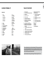
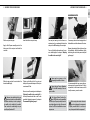
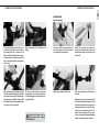
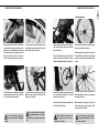
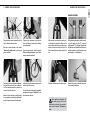
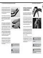
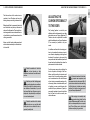
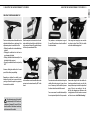
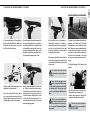
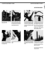
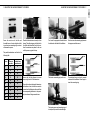
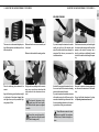
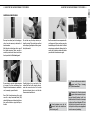
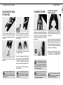
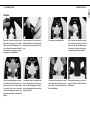
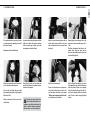
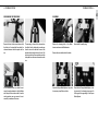
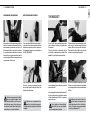
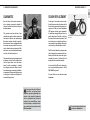
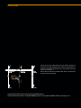
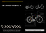
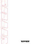
PURE CYCLING BICYCLE MANUAL Speedmax CF 1 13 14 2 3 4 a c b e 5 6 7 8 d 9 10 11 12 These are additional instructions for the Canyon Speedmax CF. Always refer to the Canyon bicycle manual road bike as well. Important: Assembly instructions page 6. Read pages 2-5 before riding for the first time. Your bicycle and this bicycle manual comply with the safety requirements of the European standard EN 14781 for road racing bicycles. 15 16 17 18 19 20 21 22 23 24 25 26 27 28 1 Canyon Speedmax CF Table of contents COMPONENTS 1 4 5 5 5 5 6 21 21 23 25 26 1Frame: a Top tube bDown tube c Seat tube dChainstay e Rear stay 2Saddle 3 Seat post 4 Seat post clamping bolt 5 Front derailleur 6 Cassette sprockets 7 Rear derailleur 8 Rear brake 9Chain 10Chainring 11 Crank set 12Pedal 13Stem 14Handlebars 15 Armrest 16 Extensions 17 Shift levers 18 Brake levers 19Headset 20 Front brake 21Fork 22Drop-out Wheel: 23Quick-release 24Rim 25Spoke 26Tyre 27Hub 28Valve 28 31 35 39 40 Table of contents Notes on these operating instructions Intended use Before your first ride Before every ride After an accident Assembly from the BikeGuard Special features of triathlon and time trial machines Time trial bar end shifters Special features of carbon wheels Adjusting the Canyon Speedmax CF to the rider Adjusting the saddle to the correct height Fore-to-aft-position and saddle tilt Adjusting the height of the handlebars Adjusting extensions and armrests Replacing extensions Shortening L-bend extensions EN D 42 Adjusting the trail of the fork 43 The brake system 43 Checking and readjusting the integrated aero brakes 44 Front brake 48 Synchronising the front brake 49 Rear brake 52 Synchronising the rear brake 52 Notes on replacing the wheels 53 The headset 54Warranty 56Guarantee 57 Crash Replacement These are additional instructions for the Canyon Speedmax CF. The chapters printed in black are for your Canyon Speedmax CF and do not have supplementary information in the Canyon bicycle manual road bike. The chapters printed in grey in these instructions require that you refer as well to the Canyon bicycle manual road bike. Important: Assembly instructions page 6. Read pages 2-5 before riding for the first time. Welcome 3 Dear Canyon Customer, Please note: These additional instructions cannot teach you all the mechanical skills of a bicycle mechanic. Even a manual as big as an encyclopaedia could not describe every possible combination of available bicycles and components. We have summarised for you in these additional instructions for the bicycle manual road bike a large number of tips concerning the use and handling of your Canyon Speedmax CF and which take into account the differences between this and a conventional bike. The chapters here supplement or even replace the relevant section in the bicycle manual road bike. Thoroughly read through these additional instructions and the bicycle manual road bike and then carry out exactly the assembly instructions given in the chapter “Assembly from the BikeGuard“. note and follow the information given in the chapter “Before your first ride” in your bicycle manual road bike. read the chapter “Intended use“ to find out on how to use your new Speedmax CF and what the permitted overall weight is (rider, clothing and baggage). carry out the minimum functional check before every ride. For more details on how to proceed, read the chapter “Before every ride“ in your bicycle manual road bike. Do not ride your Canyon Speedmax CF unless it has passed the functional check one hundred per cent! On the digital data medium enclosed with these additional instructions you will find a number of maintenance and repair routines in detail. EN 2 Welcome When carrying out these routines, be aware that the instructions and information provided in your manual only refer to this Canyon Speedmax CF and that they do not necessarily apply to other bikes. Due to numerous designs and model changes, it may be that some of the routines are not described in every detail. For that reason it is essential to follow the additional instructions of our component suppliers on the data medium and, if applicable, in the BikeGuard. For this reason this manual focuses on your newly purchased bicycle and standard components by drawing your attention to the most important notes and warnings. It is not, however, suitable to help you assemble a complete bicycle from the Canyon frameset. This manual cannot teach you how to ride a bicycle. For this reason this manual focuses on your newly purchased bicycle by drawing your attention to the most important notes and warnings. This manual cannot teach you to ride a bicycle or make you familiar with the traffic rules. Note that the instructions and tips may require further explanation depending on various factors, such as the experience and skills of the person doing the work or the tools being used, and some jobs may require additional (special) tools or measures not described in the manual. Please be aware that cycling is a hazardous activity that requires that the rider stays in control of his or her bike at all times. Furthermore, you will find numerous service movies on our website www.canyon.com that will help you carry out small repair and maintenance jobs. For your own safety, never do work on your bicycle unless you feel absolutely sure about it. Always bear in mind that on a bicycle you have no protection technology around you that could prevent injuries, such as the bodywork or the airbag of a car. Like any sport, cycling involves a risk of injury and damage. By choosing to ride a bike, you assume the responsibility for the risk. Therefore, always ride carefully and respect the other road users. Never ride under the influence of drugs, medication, alcohol or when you are tired. Do not ride with a second person on your bike and never ride without having your hands on the handlebars. Last of all, a few notes from us. Always ride carefully so as not to endanger yourself or others. Make it a habit to only ride with appropriate equipment. At the very least you should wear a properly adjusted bike helmet, sturdy shoes and suitable, brightly coloured clothing. Your Canyon team wishes you lots of fun and enjoyment with your bike! Note that the distance you need to stop your bicycle increases if you are riding with your hands on aerobars. The brake levers are not within easy reach. For your own safety, never do any assembly or adjustment work on your bike, unless you feel absolutely sure about it. If you are unsure about anything, please call our service hotline +44 (0) 208 5496001. E-mail: [email protected] Intended use 5 Notes on these operating instructions Intended use Time trial and triathlon bikes are only intended for use on roads and lanes with a smooth surface, e.g. asphalted or paved. Any usage on field tracks and off-road can cause a failure of the bicycle. PAY PARTICULAR ATTENTION TO THE FOLLOWING SYMBOLS: Please note that the aforementioned consequences will not be repeated each time the symbols appear in the manual. This symbol indicates an imminent risk to your life or health unless you comply with the instructions given or take preventive measures. This symbol warns you about actions that could lead to damage to property or the environment. This symbol signifies information about how to handle the product or refers to a passage in the operating instructions that deserves your special attention. i Concept, text, photos and graphic design: Zedler – Institut für Fahrradtechnik und -Sicherheit GmbH www.zedler.de Revised in March 2013, edition 1 These instructions do not help you to assemble a bicycle from individual parts or to repair it! The technical details in the text and illustrations of this manual are subject to change. This manual conforms with the requirements of the CE-standard EN 14781. This manual is subject to European legislation. Is an instruction manual missing? Please visit www.canyon.com for supplementary manuals. Please visit our website at www. canyon.com. There you will find the latest news and useful tips together with the addresses of our distribution partners. i © No part of this brochure may be published, reprinted, translated or reproduced, nor even in excerpted form or on electronic media or used for any other business purposes without the prior written permission of the author. All time trial and triathlon bikes as well as framesets are designed for a permissible overall weight (rider, clothing and baggage, e.g. rucksack) of 100 kg. Mavic recommends that you do not exceed an overall weight of 100 kg for triathlon bikes fitted with Mavic wheels. Canyon agrees with this. Before your first ride Before riding your new Canyon Speedmax CF for the first time, read as a minimum the chapter “Before your first ride” in your bicycle manual road bike or on the included CD. Before every ride Before your first ride, read also the chapter “Before every ride” in your bicycle manual road bike on the included CD and carefully carry out the checks described there before every ride. After an accident Canyon bikes are not approved in general for mounting child carriers. Canyon bikes are not approved in general for towing child trailers. Keep yourself informed by visiting our constantly updated website at www.canyon.com. There you will find an illustration showing in graphic form the intended use of all Canyon bikes. Mounting a pannier rack is not permitted. The only way of riding with baggage is by using a special bicycle backpack. After an accident, read also the chapter “After an accident” in your bicycle manual road bike on the included CD. After an accident on your new Speedmax CF, carry out the checks described in the chapter “After an accident”. EN 4 Notes on these operating instructions Assembly from the BikeGuard Assembly from the bikeguard 7 EN 6 Assembly from the bikeguard CHECK THE CONTENTS OF THE BIKEGUARD UNPACKING The BikeGuard contains the assembled frame with all add-on parts as well as the wheels that are sometimes packed in wheel bags, the saddle and a box with small parts, e.g. quickreleases, reflectors and pedals, as the case may be. Remove the padding (cardboard boxes), if there is any, and take out of the BikeGuard the wheels that are sometimes packed in wheel bags. Carefully lift the frame together with the rear cardboard support out of the BikeGuard. Pull the saddle with the Di2 rechargeable battery, which is mounted on the lower end of the seat post, out of the BikeGuard. If necessary, first remove the protective film from the seat post. Carefully place the frame on the cardboard support. Take the box with small parts that is at the bottom or to one side out of the Bike Guard. Assembling the bike from the BikeGuard is no witchcraft, but you should proceed with care and deliberation. Unprofessional assembly can render the bike unsafe. We would first like to make you familiar with the components of your Canyon Speedmax CF. Unfold the front cover of this manual. Here you will find the illustration of a Canyon Speedmax CF showing all the essential components. Keep this page folded out while you are reading. This means that you can quickly find in the text the component that is being referred to. When using a box cutter make sure you do not damage the component or injure yourself. Make it a rule to cut away from yourself and the component! First, open the BikeGuard. To do this, only use a box cutter or a similar knife with a very short blade. Never use any kind of knife on the bicycle itself. Hold the handlebars tightly while lifting the frame out so that they cannot drop and get damaged. Share the pleasure that your new i Speedmax brings and ask a helper to assist you in unpacking it from the BikeGuard and in assembling it. The easiest and safest way to assemble the bike is when you use a workstand or ask someone to help you. i Keep the entire packaging material as well as the BikeGuard in a dry place. If you intend to ship your Canyon or to take it with you on a trip, you will have everything at hand. i i You will not find the wheels packed in wheel bags for every Speedmax. ASSEMBLY OF THE SPEEDMAX CF Assembly from the bikeguard 9 MOUNTING THE SADDLE USING A TORQUE WRENCH Your Canyon Speedmax CF had been fully assembled at the factory and given a test run. The bicycle should be fully functional without any further adjustments being made once the assembly steps explained below have been completed. The following section gives you a concise description of the assembly. In the event that you are neither skilled nor experienced in that kind of work, please read the more detailed chapters in your bicycle manual road bike or read up on this matter on the enclosed CD. We regard the use of a torque wrench as essential so as to ensure the two parts can be fixed together securely and safely. Put the matching bit into the holder. Exceeding the maximum torque at the clamping bolts (e.g. at the stem, steerer tube or handlebars) leads to an excessively high clamping force. This can cause the component to fail and hence there is a high associated risk of accidents. In addition, the product guarantee would be null and void in such a case. Slowly turn the handle of the Canyon torque wrench. Once the bolt is getting tight, the pointer moves over the scale. Stop the turning movement as soon as the pointer reaches the number for the specified torque. Insert the Allen key fully into the screw head. Before your first ride, carry out the checks described in the chapter “Before every ride”. Do not clamp a frame tube or a carbon seat post of your Canyon in the holding jaws of the workstand! It is best to use a workstand that holds the frame from inside at three points or else ask someone to help while you assemble your bike. Screws or bolts that are too loose or are done up too tightly can cause a failure and hence lead to an accident. Always follow exactly the tightening torque details from Canyon. Before mounting the seat post on the frame, make sure that the seat tube is absolutely free of sharp edges and burrs. If necessary, open the Allen bolt at the seat post clamp on the upper side of the top tube by two or three turns. Take out the clamping mechanism. Connect the cable to the Di2 rechargeable battery that is mounted at the bottom end of the seat post. You should be able to insert the seat post easily into the frame without pressing. If you cannot, loosen the clamp a little more. The Speedmax CF has a seat post with a special aero profile. Mounting anything than the standard seat post is therefore impossible. EN 8 Assembly from the bikeguard Assembly from the bikeguard 11 HANDLEBAR MOUNTING Pull the seat post out again. Insert the built-in seat post clamp. Apply a little Canyon assembly paste to the bottom part of the seat post and inside the seat tube. Slide the seat post into the seat tube to the desired saddle height. Measure the saddle height of your previous bicycle from the middle of the bottom bracket up to the top edge of the saddle in the middle of the saddle. Then transfer the saddle height to your new Canyon Speedmax CF. i Your seat post must go into the frame as a minimum to as far as underneath the top tube and up to the MAX marking of the seat post. You can find further information on the correct saddle height in the chapter “Adjusting the saddle to the correct height”. Tighten up the Allen bolt of the seat post clamp to the prescribed torque of 4 Nm up to a maximum of 6 Nm. Be sure to read the notes given in the chapter “Adjusting the saddle to the correct height” in the bicycle manual road bike as well as the permitted tightening torques in the chapter “Recommended tightening torques”. Never apply any grease or oil to clamping areas made of carbon. If necessary, undo the four clamping bolts of the handlebars and take them out of the stem. Remove the protective film and sleeves from the handlebars. Hold the handlebars tightly while doing this so that they cannot drop and get damaged. Never ride your Canyon Speedmax CF if the MAX marking of the seat post is visible. It is recommended that you remove the protective material in general by hand. If that is not possible, it is best to use scissors, and if it is really necessary, use a box cutter. The Canyon Perfect Position System (PPS) offers you the possibility to select your Canyon perfectly tuned to your body without a test ride. For more details on the PPS visit our Website at www. canyon.com When using a box cutter make sure you do not damage the component or injure yourself. Make it a rule to cut away from yourself and the component! i EN 10 Assembly from the bikeguard Assembly from the bikeguard 13 EN 12 Assembly from the bikeguard WHEEL MOUNTING Rear wheel mounting Position the handlebars so that they are centred on the stem and that the four holes for the clamping bolts line up. Ensure that the Bowden cables and shifter cables do not get twisted or kinked, that they have smooth radii and are not pinched between the handlebars and the stem. Bring the cables into the stem without any kinking. Take the rear wheel and remove the two protective caps on the rear axle and the protective cardboard from the sprockets. Release the counternut and remove the springs from the quick-release. Remove the wooden board and pull the quick-release out of the board. Apply a little locking paste (medium strength) to the threads of the clamping bolts and tighten them up alternately to the specified tightening torques (front M4 bolts: 4 Nm; rear M8 bolts: 5 Nm). Ensure that the conical washers are in place for the two front bolts. Fit the stem cover and tighten up the two clamping bolts a few turns by hand. Then do up the clamping bolts to the specified tightening torque of 2 Nm. Open the quick-release at the rear axle. Insert the quick-release into the hollow rear wheel axle. Assemble your Canyon using the Canyon torque wrench enclosed with the BikeGuard. i Make sure there is one spring on either side of the hub. When mounting the springs on either side of the quick-release, make sure that their small-diameter ends face the hub. The quickrelease lever is mounted to the left side, i.e. opposite the chain drive. Read up on quickreleases in the chapter “How to use the quickrelease” in your bicycle manual road bike. Assembly from the bikeguard 15 Front wheel mounting Remove the protective film from both chainstays as well as the tape at the drop-out, if applicable. It is recommended that you remove the protective material in general by hand. If that is not possible, it is best to use scissors, and if it is really necessary, use a box cutter. If a tyre cannot be pushed through the brake pads without using considerable force, then let most of the air out of the tyre. The brakes have been optimised aerodynamically and therefore do not have a release lever. The brakes cannot be opened. Lay the chain on the smallest sprocket and guide the rear wheel from behind into the drop-outs of the frame. For more information on road bike i brakes read the chapter “The brake system“. You can find more on the topic of tyres and inner tubes in the chapter “The wheels” in your bicycle manual road bike. i Tighten up the counternut of the quick-release until the quick-release lever builds up force when closed. Take the front wheel and take off both protective caps from the front wheel axle. Close the quick-release and verify that the wheel is securely fixed. Read the chapter “How to use the quick-release” beforehand. Take the quick-release for the front wheel out of the small parts box. Release the counternut and remove one of the springs from the quickrelease. Ensure that the wheel is centred between the rear stays and the chainstays and is seated correctly in the drop-outs. Insert the quick-release into the hollow front wheel axle. Make sure there is one spring on either side of the hub. Inflate the tyre to the maximum pressure indicated on the side of the tyre. When mounting the springs on either side of the quick-release, make sure their smalldiameter ends face the hub. Check whether the brake pads hit the braking surfaces of the rims with their entire surface. You can find more on installation in the chapter “The wheels” in your bicycle manual road bike. i EN 14 Assembly from the bikeguard Assembly from the bikeguard 17 MOUNTING THE PEDALS The quick-release lever is mounted to the left side, i.e. opposite the chain drive. Read up on quick-releases in the chapter “How to use the quick-release” in your bicycle manual road bike. The brakes have been optimised aerodynamically and therefore do not have a release lever. They cannot be opened. Let most of the air out of the tyre if necessary. Mount the front wheel by carefully pressing the tyre together and pushing the hub together with the quick-release into the drop-outs. Tighten up the counternut of the quick-release until the quick-release lever builds up force when closed. Close the quick-release. Read the chapter “How to use the quick-release” in your bicycle manual road bike beforehand. Inflate the tyre to the maximum pressure indicated on the side of the tyre. Make sure the front wheel is accurately centred between the fork blades. Make sure the quick-release and the drop-out safety-tab are properly closed and seated. Verify that the brake is accurately centred with regard to the rim. Before mounting the pedals, check the marking on the pedal axles first. “R” stands for right pedal and “L” for left pedal. Note that the left pedal has a left-handed thread that has to be tightened contrary to the direction you are accustomed to, i.e. anticlockwise. Spin both wheels to make sure they run true. Apply a little grease on the pedal threads before screwing in the pedals. You can find more on the topic of tyres and inner tubes in the chapter “The wheels” in your bicycle manual road bike. Check whether the brake pads hit the braking surfaces of the rims with their entire surface. For more information read the chapter “The brake system”. EN 16 Assembly from the bikeguard Screw each pedal manually into the thread of its crank by two to three full turns. Continue by using a pedal spanner to tighten the pedals firmly. Assembly from the bikeguard 19 Fix the white reflector to the handlebars and the red reflector to the seat post as well as the spoke reflectors to the spokes. Some types of pedal have to be tightened with an Allen key. Check the reliable fit of the pedals after about 100 km (60 miles). The pedals can come loose, and this can destroy the thread and throw the rider off his bike. Also check the reliable fit of the other bolts according to the prescribed tightening torques. Di2 RECHARGEABLE BATTERY AND CHARGER CHECKING AND ADJUSTING The Di2 rechargeable battery of the Canyon Speedmax CF is located at the lower end of the seat post. Check the proper functioning of the gears. Shift through all the gears. Make sure that the rear derailleur does not collide with the spokes when the chain runs on the largest sprocket. The seat post rechargeable battery is charged by means of a USB connection at the handlebar distributor. Read up on how to adjust the gears in the chapter “The gears“ in your bicycle manual road bike. Only charge the rechargeable battery with the battery charger that is supplied. Do not use any other battery charger from any other maker, even if the plugs of the battery charger fit into your rechargeable battery. Read up on the road traffic regulations in the country where you use the road bike. You can find further information i in the chapter “Shimano Di2” in your bicycle manual road bike or at www. shimano.com After the wheel mounting do a brake test when stationary. Actuating the brake lever should generate a clear-cut braking response before the lever touches the handlebars. EN 18 Assembly from the bikeguard Special features of triathlon and time trial machines 21 EN 20 Assembly from the bikeguard Special features of triathlon and time trial machines Your Speedmax CF is equipped with special aerobars for triathlons and time trials, where an especially aerodynamic seating position is required. Adjust the position of the saddle and handlebars and check that the handlebars, grips and seat post are securely fastened, as described in the chapter “Adjusting the Canyon Speedmax CF to the rider”. As a rule, the seating position is set to be somewhat more upright on a triathlon bike than for a time trial machine. You can find further information on the seating position in the chapter “Adjusting the Canyon Speedmax CF to the rider”. Time trial bar end shifters With these aerobar models the shift levers are positioned at the extensions’ ends, and the brake levers at the ends of the basic (bull-horn) handlebars. When you ride with your back in a horizontal position, the brake levers are out of reach and the reaction time is longer, which makes your stopping distance longer. For this reason it is very important to anticipate problems when riding. Never ride your Canyon if the MAX marking of the seat post is visible. After completing the assembly and checks it is essential to give your Canyon a test ride in a level, unfrequented area (e.g. in a parking lot)! Wrong assembly or improper adjustments that become apparent in road traffic can make you lose control of your Canyon with unforeseeable consequences! The position of the basic handlebars and also the extensions under the armrests can be set to suit your personal requirements. Make sure your forearms are always comfortably rested, i.e., your elbows should project beyond the armrests a little towards the rear. Triathlon bikes and time trial machines have specific riding characteristics. Make yourself gradually familiar with your new bike in an unfrequented area and approach the riding characteristics step by step. Therefore, when you start riding a triathlon or time trial bike, practice under the guidance of an experienced trainer. i Special features of carbon wheels You only need to gently push control buttons with the shift levers with Di2 at the ends of the extensions in triathlons and time trials. Shift to the bigger sprockets with the upper control button. Press the lower control button to shift to the smaller sprockets. As carbon wheels are made of carbon fibrereinforced plastic they come with particular aerodynamic properties and a low weight. There is the option to have the control button function changed by your bicycle dealer if desired. To do this a special test device from Shimano is required that is also used for troubleshooting. As the braking surfaces are made of carbon, there are some things to bear in mind. Only use brake pads that are suitable for carbon wheels. Our recommendation is to always use those from the wheel manufacturer, the same as those that Canyon supplied as original brake pads with the specific wheel. The control buttons transmit the shifting to the rear derailleur via the cable (Di2). Then the rear derailleur swivels, causing the chain to climb onto the next sprocket. It is therefore important when changing gears to continue pedalling smoothly without force as long as the chain is moving between sprockets or chainrings! There are, however, special guides in the chainrings of today’s bikes which allow for switching gears under load. Changing gears under load shortens, however, the service life of your chain considerably. Furthermore, this may cause the chain to jam between the chainstay and the chainrings (also referred to as “chain-suck”). Therefore, avoid changing gears while pedalling hard, and in particular when changing gears with the front derailleur. Special features of carbon wheels 23 EN 22 Special features of triathlon and time trial machines In addition, only use pad holders from Canyon! Carbon brake pads usually wear down faster than conventional brake pads. For that reason, check their adjustment regularly and replace the pads before long journeys or competitions as a precautionary measure. In particular, if it will be wet. Keep in mind that the braking response of the rims needs getting used to, and in particular in wet conditions. Therefore, test your brakes in a place free of traffic until you have full control of your bicycle. Please note as well the particulars given in the chapter “Special characteristics of carbon” in your bicycle manual road bike. i Be sure to read the enclosed operating instructions of the gear manufacturer. Fundamentally speaking, use the original pads of your Canyon Speedmax CF with standard wheels. Note that the distance you need to stop your bicycle increases if you are riding with your hands on aerobars. The brake levers are not within easy reach. Shimano and Campagnolo offer carbon brake pads, as well. These are, however, designed to match Shimano and Campagnolo rims. i i i Adjusting the Canyon Speedmax CF to the rider 25 EN 24 Special features of carbon wheels Adjusting the Canyon Speedmax CF to the rider The brake surfaces of the carbon rims are sensitive to heat. Therefore avoid any drag braking when you are riding in the mountains. Riding downhill with a permanently activated rear wheel brake may heat up the material and result in deformation. The rim could sustain damage and the inner tube could burst or a glued tubular tyre could come undone, thus causing an accident. The (seating) position is crucial for your wellbeing and the development of your riding performance on your Canyon Speedmax CF. Therefore, be sure to adjust both the saddle and the handlebars of your Canyon Speedmax CF as accurately as possible to suit your needs. Always use both brakes simultaneously and release them intermittently to allow the material to cool off. In triathlons and time trials the seating position is set to produce the minimum air resistance. However, depending on the length and duration of the sections to be covered, this aero position with low handlebars placed well forward can lead to problems that reduce the performance that can be achieved. Check the condition of the brake pads at short intervals, as they might wear down faster than with aluminium rims. Note that your bike’s braking power is greatly reduced in wet conditions. Do not go for a ride if it is about to rain or in wet conditions. Nevertheless, if you will find yourself with your Canyon on a wet or damp road, ride particularly carefully and at a much reduced speed. Check the condition of the brakes and make sure you only ride with brake pads that are suitable for the respective (carbon) rims! i For that reason ensure when adjusting the fore-to-aft position, the height of the handlebars and the position of extensions and armrests that the resulting seating position can be maintained over the entire distance of your training or competition sections without causing tension, restricted mobility and/ or breathing or even a painful posture that would affect your performance. Typically a more upright position is chosen for triathlons than for time trials, which are mostly over shorter distances. All the tasks described in the following require some experience, and the appropriate tools and manual skills. If you are unsure about how to do something, it will be better just to check your seating position. If in doubt, ask an expert to adjust your Canyon Speedmax CF. After carrying out assembly work, always make a short check (see the chapter “Before every ride”) and do a test ride in an unfrequented place or on a quiet road. This will allow you to safely check whether everything is in good order. Align the handlebars such that you still have your Canyon Speedmax CF fully under control even in critical riding situations and can operate the steering and the brakes at all times without any restrictions. Check this by carrying out an exhaustive test ride in a place free of traffic or on a quiet road. Sit on the saddle and put one heel on the pedal at its lowest point. Your leg must be fully stretched in this position. Ensure that your hips remain straight when doing this. In order to adjust the saddle height, undo the Allen bolt at the seat post clamp on the upper side of the top tube. Bear in mind that any changes to the position of the saddle, handlebars, extensions and armrests also affect the other parameters of the seating position as a result. Correct them as required so that the final result is a seating position on your triathlon or time trial bike that is safe, comfortable enough and nonetheless aerodynamically optimal. Once it has been released, you can adjust the height of the seat post. Do not use brute force if the seat post does not move easily inside the seat tube. If necessary, contact our service hotline at +44 (0) 208 5496001. Do not pull the seat post out so far as to let the marking on the shaft come into view. Adjusting the saddle to the correct height The correct saddle height is all a matter of how it allows you to pedal. Important: When pedalling, the ball of your big toe should be positioned above the centre of the pedal axle. With your feet in this position you should not be able to stretch your legs completely at the lowest point. If the saddle is too high, you will have trouble passing through the lowest point and your pedalling will become awkward. If the saddle is too low, you may soon find your knees aching. You can check the height of your saddle in the following simple way. This is best done wearing flatsoled shoes. Adjusting the Canyon Speedmax CF to the rider 27 EN 26 Adjusting the Canyon Speedmax CF to the rider If you are adjusting and checking it can be helpful if you clamp your Speedmax CF into a roller-type home trainer and set the front wheel to the same height. In this way you can try out the seating position with no risk. A mirror makes it easier to check this. i If you are taking part in time trial competitions you should bear in mind that the international sport cycling association UCI has set stipulations regarding the horizontal position of the saddle. Ensure when adjusting the seating position that these stipulations are complied with, otherwise, in the worst case, you could be disqualified from the competition. i Clamp the seat post tightly again. Do this by tightening up the Allen bolt at the seat post clamp on the upper side of the top tube to the prescribed torque of 4 Nm up to a maximum of 6 Nm. Does the leg stretch test now produce the right result? Check by moving your foot and pedal to the lowest point. If the ball of your big toe is exactly above the pedal centre (ideal pedalling position) your knee should be slightly bent. If this is the case, the saddle height has been adjusted to the correct height. Check whether you can balance safely on your bike while sitting on the saddle by stretching your feet to the ground. If that is not the case, you must lower the saddle a little, initially at least. Do not ride if the seat post has been pulled out beyond the line with the MAX marking! The seat post might break or cause severe damage to the frame. Under no circumstances grease the seat tube of a carbon frame. Once they have been greased, carbon fibre components may never again ensure reliable clamping! Tighten carefully by approaching the prescribed maximum torque in small steps (0.5 Nm increments) whilst constantly checking the proper fit of the component. Never exceed the maximum tightening torque prescribed by Canyon! Do not overtighten the seat post clamping bolt. Otherwise the seat post or the frame can be damaged. Risk of an accident! Adjusting the Canyon Speedmax CF to the rider 29 EN 28 Adjusting the Canyon Speedmax CF to the rider Fore-to-aft-position and saddle tilt The fore-and-aft position of the saddle can be adjusted individually over a wide range. Four adjustment options are available for this: Shifting the saddle rails in the saddle clamping head Clamping the saddle rails via the front or rear clamping slide holes Shifting the saddle slide horizontally in the slotted hole of the seat post. Turning the saddle slide on the seat post by 180° Slide the seat post in the seat tube to the desired saddle height and tighten the Allen bolt at the seat post clamp to the specified torque of 4 Nm up to a maximum of 6 Nm. This produces a wide adjustment range of 0 mm to 85 mm distance from the middle of the bottom bracket. If the range is not enough, you can undo the two almost vertical bolts. Shift the saddle rails in the saddle clamping head. In the triathlon version the saddle slide on the seat post can be turned around by 180° in the frame. First undo the two Allen bolts which clamp the saddle slide to the seat post by two or three turns. If necessary, hold the bolts in place on the other side with another Allen wrench. Ensure when doing this that the saddle rails have been positioned in such a way that the clamp of the seat post is within the prescribed range. If there is no marking at the saddle rails, the clamping must be done on the straight portion of the rails and on no account on the front or rear bend. Risk of breakage! However, shifting the saddle rails in the seat post will also affect your pedalling. Depending on whether the saddle is positioned more to the front or more to the rear, your legs will reach the pedals to a greater or lesser extent from behind. You can now move the saddle horizontally in the seat post and adjust the tilt to your needs. The adjustment range of the saddle is determined by the UCI and is over a distance of between 50 mm and 110 mm from the middle of the bottom bracket up to the front end of the saddle. i Adjusting the Canyon Speedmax CF to the rider 31 Adjusting the height of the handlebars If the adjustment range is still not sufficient, then fully undo all the Allen bolts. Remove the saddle slide from the seat post, turn it round by 180° and put it back in again. As a further option, the saddle clamping bolts can optionally be tightened up in the front or rear clamping slide holes at the saddle clamping head. When fixing the saddle, make sure the saddle clamping head lies close around the saddle rails and do up both Allen bolts to the prescribed tightening torque of 4 Nm. Set the saddle so that it is horizontal or inclined slightly forward. If the saddle is inclined too far forward you cannot pedal without stress. You will constantly have to lean against the handlebars to prevent yourself from slipping off the saddle. After fastening the saddle, check whether it resists tilting by bringing your weight to bear on it once with your hands on the tip and once at the rear end. The height of the handlebars determines the inclination of the upper body. The deeper the handlebars, the more inclined the upper body. This means a more streamlined position for the rider and more weight to bear on the front wheel, but the extremely inclined position proves less comfortable, as the strain on wrists, arms, upper body and neck will increase. The Canyon Speedmax CF is offered in two versions: Use a torque wrench with bits and never exceed the maximum tightening torque! Install the saddle, saddle clamping head and saddle slide in the new positions. Ensure when fitting the Allen bolts that the nuts, spacers and bolts are put on in the right order and tighten them up only so far that the saddle clamping head can still be moved. Now set the desired amount of tilt of the saddle. Tighten the lower Allen bolts evenly so the saddle remains at the desired angle. Use a torque wrench. In the event your seat post is not firmly clamped at 8 Nm, tighten it further in small steps (0.5 Nm increments) up to a maximum torque of 10 Nm. Do not exceed the maximum tightening torque! Never ride if the seat post has been pulled out beyond the MAX marking or if the saddle has been clamped outside the clamping area! The seat post might break or sustain damage. Risk of an accident! Check the screwed and bolted connections once a month with a torque wrench in accordance with the values given in the chapter “Recommended tightening torques.” Time Trial: with a flat stem, low “drop” handlebars and S-bend extensions (III) Triathlon: with a higher stem, straight “flat” handlebars and L-bend extensions (I) The stem may only be replaced by Canyon. Contact our service hotline at +44 (0) 208 5496001. EN 30 Adjusting the Canyon Speedmax CF to the rider Adjusting the Canyon Speedmax CF to the rider 33 EN 32 Adjusting the Canyon Speedmax CF to the rider (I) L-Bend (II) Straight (III) S-Bend Straight extensions (II) are offered as an accessory. These components can also be combined in other ways to achieve an optimal seating position. Contact our service hotline at +44 (0) 208 5496001. The triathlon stem can be set higher by up to 4 cm by installing additional spacers (compared to the stem without spacers). One spacer is mounted as standard. A second spacer is part of the standard scope of supply of the Speedmax CF. Two additional spacers can be ordered as the TRI Spacer Kit (accessory). We most strongly recommend that the mounting of a total of three or four spacers should be done in our workshop, since all the cables need to be laid again. Remove the handlebars. Undo the three clamping bolts of the stem and lift the stem up a little. Ensure that all the spacers are mounted with the collar upwards and, where applicable, inserted inside one another, so that the final result is positive locking to the stem, which is inserted last of all. In order to mount or remove spacers, undo the side clamping bolts of the stem cover and remove the cover. Install a maximum of two spacers to achieve the desired height for the handlebars. You can have two more spacers mounted in our workshop. Then insert the relevant M5 clamping bolts: Contact our service hotline at +44 (0) 208 5496001. 2 to 3 spacers: in the middle the 40 mm bolt and outside a 70 mm bolt in each case Then undo the four handlebar clamping bolts and remove them together with the conical inserts for the front clamping bolts. 0 to 1 spacers: in the middle the 20 mm bolt and outside a 50 mm bolt in each case 4 spacers: in the middle the 50 mm bolt and outside an 80 mm bolt in each case Adjusting the Canyon Speedmax CF to the rider 35 Adjusting extensions and armrests Do the clamping bolts up to the prescribed tightening torque of 5 Nm. Ensure that the Bowden cables and shifter cables do not get twisted or kinked, that they have smooth radii and are not pinched between the handlebars and the stem. Apply a little locking paste (medium strength) to the threads of the clamping bolts and tighten them up alternately to the specified tightening torques (front M4 bolts: 4 Nm; rear M8 bolts: 5 Nm). The handlebars and extensions offer a wide variety of adjustment options. You can choose between handlebars without drop and handlebars with 42 mm drop. The height of the armrests can also be changed by using additional 5 mm spacers. In both versions the width of the handlebars is 420 mm. Position the handlebars so that they are centred on the stem and that the four holes for the clamping bolts line up. Insert the conical inserts of the front clamping bolts. Put the cover of the stem in place and tighten up its clamping bolts to the prescribed torque of 2 Nm. The height of the extensions and the armrests can be adjusted by various arrangements of the clamps for the extensions and the supplied spacers in 5 mm steps. A maximum of three spacers on top of one another may be used here. EN 34 Adjusting the Canyon Speedmax CF to the rider Adjusting the Canyon Speedmax CF to the rider 37 EN 36 Adjusting the Canyon Speedmax CF to the rider Ensure the correct use of the bolts and threaded sleeves of various lengths and that in each case two connecting rings are inserted between the spacers. Check that the extensions sit correctly in their clamps. The rubber stoppers with the hole for the shifter cable should be flush at the rear, then the extensions are pushed to the rear until they come up against the stop. First insert the appropriate threaded sleeve from below into the hole of the handlebars. Use the narrow red terminating rings between the top spacer and the armrest. Ensure also that the alignment is correct when using L-bend or S-bend extensions. Then insert a connecting ring in each case. The extension clamp can also be mounted underneath the handlebars. Do not forget to insert the connecting rings. The possible combinations are listed in the following table. Spacers M5 screws from above Threaded sleeve from underneath 0 40 35 5 40 35 10 40 55 15 40 55 20 60 55 25 60 55 30 60 55 35 60 55 40 60 55 45 60 55 If you wish to replace the standard extensions with another version, the shift levers must be removed and installed again afterwards. Note the corresponding information in the operating instructions of the gear manufacturer. Then insert spacers and connecting rings alternately until you reach the desired height. Adjusting the Canyon Speedmax CF to the rider 39 EN 38 Adjusting the Canyon Speedmax CF to the rider Replacing extensions The armrests can be mounted lengthways in four different positions and sideways in three different positions. Make sure that the armrests are correctly and firmly fixed. Make a test ride to check the seating position. Place the reinforcing plate underneath the armrest. Apply a little locking paste (medium strength) to the threads of the relevant clamping bolts and tighten them up to the prescribed tightening torque of 5 Nm. Only glue the foam padding onto the armrests once you are sure that you have found the right position for the extensions and armrests. The shape of the spacers is designed around the basic handlebars. Ensure that the spacers are aligned correctly. i Ensure that you only clamp the Lbend extensions within the marked area (“End of clamping area”). If you wish to swap the extensions for another model, you must first of all undo the cable plug of the shifter cable that runs through the extensions. Only then can you unscrew the installed extensions. Take the new extension in your hand and guide the cable into the extension and through the opening to the outside. If necessary, use a loop (e.g. made from a cable binder) to make it easier to thread the cable through the opening. Now hold the unscrewed extensions firmly at the rear and pull off the extension clamping piece in the direction of the cable. If you wish to replace the standard extensions with another version, the shift levers must be removed and installed again afterwards. Note the corresponding information in the operating instructions of the gear manufacturer. Now push the extension clamping piece back on and mount the extensions on the handlebars. Three different versions of extensions are available. You can choose between L-bend, S-bend and straight versions. i You can find further information in the chapter “Adjusting extensions and armrests”. Adjusting the Canyon Speedmax CF to the rider 41 EN 40 Adjusting the Canyon Speedmax CF to the rider Shortening L-bend extensions Once you have found your final seating position, it may be necessary to shorten the Lbend extensions. Mark the place at which you wish to saw off the L-bend extensions. Orient yourself towards the printed scale. Never saw off more than beyond the line “End of cutting area”. Do not blow away the chips and dust produced by sawing. Pick up the chips and dust with a damp rag and dispose of the rag immediately afterwards! Do not clamp in a vice the L-bend extensions to be sawn off, as that could destroy them. Clamp the L-bend extensions in a suitable device, for example, a special bracket. Carefully deburr the cut end with a finetoothed file. Run the file along the tube towards the sawn end and not in the other direction, otherwise there is a risk that the fibrous material could fan out. Saw off the L-bend extensions with a metal saw with a sharp fine-toothed blade (24t) and with light pressure at the marking. Ensure that you do not inhale or ingest the chips or the dust. Seal the cut end with a two-component adhesive (epoxy resin), clear varnish or superglue. Immediately wipe off to the side of the L-bend extensions any residues of adhesive after the sealing. Let the adhesive harden fully before you mount the L-bend extensions again. Do not saw off extensions without a printed scale (“End of clamping area”). Risk of an accident! L-bend extensions may only be sawn off within the marked area (“End of cutting area”). Shortening the L-bend extensions requires a certain amount of experience and should, therefore, be left to a skilled mechanic. If in doubt, ask an expert to adjust your Canyon Speedmax CF. If you still wish to do this yourself, restrict yourself to jobs for which you are equipped and have the necessary knowledge. The brake system 43 Adjusting the trail of the fork Due to the innovative Rake Shift inserts in the forks the trail and hence also the riding behaviour can be modified to suit the wishes of the rider. In total, three positions are available to choose from (front and rear) by replacing and turning around the asymmetric drop-outs from left to right. The brake system Checking and readjusting the integrated aero brakes Canyon has developed for the Speedmax CF a special aero braking system that is integrated into the fork and the frame. Its special design requires that you carefully note the following information regarding operation, adjustment and checking. Due to its special construction, the Speedmax brake has two systems to adjust. One for the cable length and another to take up wear in the brake pads. Before you use any wheels other than the ones supplied as standard, please contact our service hotline at +44 (0) 208 5496001. The middle position is obtained by installing the symmetrical inserts. Open the bolt of the Rake Shift with a TX 10 Lwrench (Torx). Now you can remove the Rake Shift insert. Ensure that the Rake Shift is aligned at both ends of the drop-outs so that the drop-out safety tabs (projections) point outwards. The trail is thus changed by 2.5 mm in each case. A long trail (= axle position further back) makes for somewhat steadier running, a short trail (= axle position further forward) makes for a somewhat more agile geometry. Then insert the bolts and do them up to a torque of 0.9 Nm. Note that different bolts and spacers are required at the brake pads for the various rim widths. The brake could be inoperative without the correct components. Risk of an accident. The symmetrical inserts can be obtained from Canyon as accessories. Contact our service hotline at +44 (0) 208 5496001. Always use the original brake pad holders. The brake may be inoperative with holders or pads from other manufacturers. Risk of an accident! i Check as a minimum after riding every 500 kilometres and after a long ride in the rain the adjustment of the front and rear brakes with the aid of the supplied Canyon Brake Adjuster. This must fit without fail the wheels that are mounted – see the marking. Do not use any rims whose width does not match the Canyon Brake Adjusters. Risk of an accident! EN 42 Adjusting the trail of the fork The brake system 45 EN 44 The brake system Front brake Remove the front wheel to check the brake. Release the clamping bolts of the Brakebooster and remove the Brakebooster. Caution: the front brake is now only held loosely in the brake bosses. Then tighten up again the clamping bolts of the Brakebooster. Correct the position of the cable carrier as required with the aid of the associated cable adjuster that is located underneath the stem cover. The triangle must be adjusted like this. If that is not the case, adjust the two brake arms accordingly by screwing the relevant setscrew in or out with a 1.5 mm Allen wrench. The setscrews for the front brake are accessible from the inside over the brake holder. Place the Canyon Brake Adjuster that matches the width of the rim onto the bolts on the brake bosses and first of all check whether the triangular cable carrier is positioned correctly: the clamping piece must lie flush against the upper edge of the Canyon Brake Adjuster. If its adjustment range is not sufficient, undo the two clamping bolts at the cable carrier and correct the cable adjustment. Then tighten up the two clamping bolts to the prescribed torque of 2.5 to 3 Nm. If the position of the cable carrier is correct, check whether the brake pads have an air gap of around 1 to 1.5 mm on each side of the Canyon Brake Adjuster. Check whether the pads have an air gap of around 1 to 1.5 mm on each side of the Canyon Brake Adjuster. The brake system 47 EN 46 The brake system If the pads cannot be set correctly, then they are worn and must be replaced by new brake pads (from Canyon!). In order to replace the pads together with the holders or to install other spacers, including bolts, for another type of wheel, remove the two stoppers from the fork blades. Mount the new brake pad together with the holder and the spacer and bolt in the same order and alignment that you removed them previously. Always tighten up the retaining bolts of the brake pads to the prescribed torque of 5 to 7 Nm. Check the adjustment of the brakes as described above. After that, adjust the two brake arms with an Allen wrench with the aid of the the Brake Adjuster. Firmly hold the brake pad and holder and undo the bolt. Remove it completely and pay attention to its alignment. Mount the front wheel again. Take the Canyon Brake Adjuster off, remove the clamping bolts and put the Brakebooster back into position. Tighten up its clamping bolts to the prescribed torque of 2.5 Nm. Ensure that the clamping bolts have a locking paste (“Loctite”, medium strength) applied to them. Completely undo the small Allen bolt. Pull the worn brake pads out of the pad holders. Pay attention to their alignment. Push into the pad holder the new original brake pads that match the rim. Tighten up the Allen bolt to 2 Nm. Check the adjustment of the brakes as described above. The brake system may only be fitted with the original brake pads that are supplied or else with those that match the wheel if a different wheel has been fitted. Otherwise there is a risk of brake failure! Ensure that the brake pads are aligned correctly to the braking surface of the rim. You can find further information in the chapter “Checking and readjusting road bike brakes” in your bicycle manual road bike. The brake system 49 Synchronising the front brake Operate the front brake several times while the bike is in the stand and then check the clearance between the brake pads and the rim. If the clearance differs, turn back the setscrews for synchronisation in the fork blades until they are flush on the outside. From this starting position you may screw in the setscrews by a maximum of five turns. EN 48 The brake system Rear brake The screwing in of one of the setscrews has the effect that the brake pad is moved away from the rim on this side and the one of the opposite side is brought closer to the rim. The correct position has been reached once both brake pads have the same clearance from the rim. Release the clamping bolts of the Brakebooster and remove the Brakebooster. Now take off the small spring. Remove the rear wheel to check the brake. Insert the Canyon Brake Adjuster; it may also be necessary to pull the rear brake. Check that the Canyon Brake Adjuster is sitting correctly: the clamping piece must lie flush against the upper edge of the Canyon Brake Adjuster. The brake system 51 EN 50 The brake system Correct the position of the cable carrier as required with the aid of the associated cable adjuster that is located underneath the stem cover. Once the position of the cable carrier is correct, the spring can be put back. Check whether the pads have an air gap of around 1 to 1.5 mm on each side of the Canyon Brake Adjuster. If the pads cannot be set correctly, then they are worn and must be replaced by new brake pads (from Canyon!). Read the description above of the work steps for the front brake and follow them for the rear brake. Press the two brake arms together, put the Brakebooster back into position and tighten up its clamping bolts to the prescribed torque of 2 Nm. Ensure that the clamping bolts have a locking paste (“Loctite”, medium strength) applied to them. If its adjustment range is not sufficient, undo the two clamping bolts at the cable carrier and correct the cable adjustment. If that is not the case, adjust the two brake arms accordingly by screwing the relevant setscrew in or out with a 1.5 mm Allen wrench. The setscrews for the rear brake are accessible from the outside. Ensure that the brake pad holders are closed in the direction of rotation of the rim. With the rear brake the holder is then closed underneath. Now the rear wheel can be mounted again. Then tighten up the two clamping bolts to the prescribed torque of 2.5 to 3 Nm. Always tighten up the retaining bolts of the brake pads to the prescribed torque of 5 to 7 Nm. Remove the Canyon Brake Adjuster. Ensure that the brake pads are aligned correctly to the braking surface of the rim. You can find further information in the chapter “Checking and readjusting road bike brakes” in your bicycle manual road bike. The headset 53 EN 52 The brake system Synchronising the rear brake Notes on replacing the wheels The headset Operate the rear brake several times while the bike is in the stand and then check the clearance between the brake pads and the rim. If the clearance differs, turn back the setscrew for synchronisation in the brake arm whose brake pad has the greater clearance from the rim far enough until both brake pads have the same clearance from the rim. If you use wheels with different rim widths, it is essential to use the various relevant Brake Adjusters in connection with the spacers of the brake pads. Contact our service hotline at +44 (0) 208 5496001. If your bicycle makes knocking noises when you are riding or braking, you should check the headset. Carry out the check in the headset that is out of sight as described in the chapter “The headset” in your bicycle manual road bike. Tighten up these three threaded pins clockwise, using a 2 mm Allen wrench with great delicacy. Start in each case with half a turn. Check again for play. Tighten up by another half turn as required and check again. 1 2 3 If you change from aluminium to carbon or vice versa, you must also change the pads and use the original brake pads. Adjust the brake as described above. The brake system may only be fitted with the supplied original brake pads and brake holders, plus the associated bolts and spacers. Also, always use the relevant Canyon Brake Adjuster. Otherwise there is a risk of brake failure! Pads that are not matched to the wheel or are adjusted incorrectly can make the brake inoperative. Risk of an accident! If you can feel any play in the bearings, undo the side clamping bolts of the stem cover and remove the cover. In the integrated headset of the Speedmax CF the play of the bearings is adjusted by means of three threaded pins (1-3) at the pressure plate in the stem. Do not tighten up these adjusting bolts fully, they are only intended for a fine adjustment of the play! Be sure not to tighten the bearing too much. Put the cover of the stem in place and tighten up its clamping bolts to the prescribed torque of 2 Nm. Adjusting the headset requires a certain amount of experience and should, therefore, be left to a skilled mechanic. If in doubt, ask an expert to adjust your Canyon Speedmax CF. WARRANTY AND GUARANTEE 55 Warranty Your bike was manufactured with care and delivered to you largely preassembled. We are obliged by law to guarantee that your bike is free of any defects which considerably reduce its value or fitness for use or make it worthless or useless. You have full warranty rights within the first two years after purchase. We are your contact in the event of defects and you can get in touch with us at the stated address. In order for your claims to be processed smoothly it is necessary that you present your receipt. Therefore, please keep your receipt in a safe place. To ensure a long service life and good durability of your bike only use it for its intended purpose (see chapter “Intended use”). Also observe the permissible load specifications and the instructions on transporting baggage and children (see chapter “Intended use”). The manufacturers’ assembly instructions (above all the torque settings for bolts) and the prescribed maintenance intervals must be strictly followed, as well. Please observe the tests and routines listed in this manual or in any other manual enclosed with this delivery (see chapter “Service and maintenance schedule”) as well as any instructions as to the replacement of safety-relevant components, such as handlebars, brakes etc. EN 54 WARRANTY AND GUARANTEE A Note on Wear Always use your bike for its intended use We wish you safe and happy cycling wherever your bike takes you. If you have any questions, please call our service hotline at +44 (0) 208 5496001. Enclosed with the delivery you will i find the operating instructions of the component manufacturers. Here you will find all details about use, maintenance and care. This manual contains multiple references to these specific and detailed operating instructions. Please make sure the individual operating instructions for clipless pedals and gear and brake components are in your possession and keep them in a safe place together with this leaflet and the manual. Carbon is a composite material which is used for weight-optimised designs. Surface irregularities on carbon components (small boils and pores) are unavoidable for reasons inherent in the manufacturing process. This does not constitute a defect. i Some components of your bike are subject to wear due to their function. The rate of wear depends on care and maintenance as well as on the way you use your bike (kilometres travelled, rides in the rain, dirt, salt etc.). Bikes that are often left standing in the open may also be subject to increased wear through weathering. Brake pads with worn down wear indicators, i.e. grooves, (bottom brake pad) must be replaced by original spare parts These components require regular care and maintenance. Nevertheless, sooner or later they will reach the end of their service life, depending on conditions and intensity of use. Parts that have reached their limit of wear must be replaced. This applies to the following parts: chain, cables, grip coverings or bar tape, chainrings, sprockets, pulleys, gears cables, tyres, saddle covering (leather) and brake pads. The brake pads of rim brakes are subject to wear due to their function. If you use your bike for competitive cycling or in hilly terrain, they may have to be replaced quite frequently. Regularly check the condition of the pads and have them replaced by a dealer. Have the thickness of your rims checked at the latest when you are through your second set of brake pads Rims with rim brakes Braking causes wear not only to the brake pads but also to the rims. Therefore, check your rims regularly, e.g. when pumping up the tyres. Rims with wear indicators have rings or a gap that come into view when the rim reaches its limit of wear. Take note of the specifications given on the rim. Ask an expert to examine the remaining thickness of the rims at the latest when you are through your second set of brake pads. Signs of deformation or fine cracks that appear in the sides of a rim when you increase the tyre pressure are an indication that the rim has reached the end of its service life. In this case the rim must be replaced. Crash Replacement 57 Guarantee Crash Replacement Over and above the statutory warranty we give a voluntary guarantee of altogether 6 years on the frames and forks of racing and triathlon machines. In the event of an accident or severe crash, the high forces exerted on the frame and the fork can lead to structural failure during subsequent use. With our Crash Replacement (CR) program we offer you the opportunity to replace your damaged Canyon frame at a greatly reduced cost. This offer is valid up to three years after the date of purchase. You’ll receive the same or a similar frame from our current product range (without add-on parts such as seat post, front derailleur or stem). This guarantee runs from the date of purchase and only applies to claims made by the initial buyer. It does not cover paint damage. We reserve ourselves the right to repair defective frames or forks or to replace them with the relevant successor model. These issues can be claimed under guarantee only. Additional costs, such as assembly and transport costs etc., shall not be borne by us. Six-year guarantee EN 56 WARRANTY AND GUARANTEE Crash Replacement – Damaged Canyon frames are replaced at reduced prices The CR-service is limited to the original owner and to damages that compromise the functionality of the bike. We reserve the right to suspend this service if we detect that the damage has been caused unreasonably. The guarantee does not cover damage caused by improper or other than the intended use, such as neglect (poor care and maintenance), crashes, overloading or resulting from changes made to the frame or fork or from the mounting or remounting of additional components. Damage resulting from jumps or other types of overstress are likewise not covered by the guarantee. In order to claim the CR-service, please contact our service hotline by phone at +44 (0) 208 5496001 or by email. For more details visit our website at www. canyon.com Canyon road, time trial, triathlon or track bikes are high-end sports equipment, representing lightweight construction as the pinnacle of engineering. Also be a professional when it comes to handling of the material. Misuse, unprofessional assembly or insufficient servicing can render the racing machine unsafe. Risk of an accident! i For more information about the use, read chapter “Intended use”. PURE CYCLING You will find us easily at Karl-Tesche-Strasse 12, Koblenz. Coming from motorway junction A48, exit Koblenz Nord, follow the road B9 in direction of Koblenz. On the Mosel Bridge filter to the second lane from the right into the city roundabout. Take the first exit in direction of Cochem. After approx. 1 km (0.6 miles) turn right at the first traffic light. Canyon Bicycles GmbH / Karl-Tesche-Straße 12/ D-56073 Koblenz Order and information hotline: +44 (0)208 5496001 / Order-fax: +49 (0)261 4040050 / E-Mail: [email protected]