1
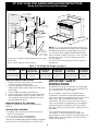
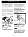
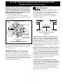
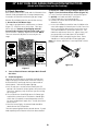
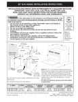
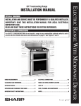
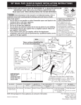
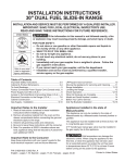
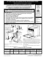
30" & 36" DUAL FUEL RANGE INSTALLATION INSTRUCTIONS
(Model with Electric Oven and Gas Cooktop)
INSTALLATION AND SERVICE MUST BE PERFORMED BY A QUALIFIED INSTALLER.
IMPORTANT: SAVE FOR LOCAL ELECTRICAL INSPECTOR'S USE.
READ AND SAVE THESE INSTRUCTIONS FOR FUTURE REFERENCE.
OBSERVE ALL GOVERNING CODES AND ORDINANCES.
If the information in this manual is not followed exactly, a fire
or explosion may result causing property damage, personal injury or death.
FOR YOUR SAFETY:
— Do not store or use gasoline or other flammable vapors and liquids in
the vicinity of this or any other appliance.
— WHAT TO DO IF YOU SMELL GAS:
• Do not try to light any appliance.
• Do not touch any electrical switch; do not use any phone in your building.
• Immediately call your gas supplier from a neighbor's phone. Follow the
gas supplier's instructions.
• If you cannot reach your gas supplier, call the fire department.
— Installation and service must be performed by a qualified installer, service
agency or the gas supplier.
29 7/8" Min.
(75.9 cm Min.)
C
Note: For
appliances
installed in the
state of
Massachusetts
see page 3.
B
WALL
W A LL
Refer to your
serial plate for
applicable agency
certification
See
note
If there is a wall:
7" Min.
(17.78 cm Min cm Min.)
Left side
18" Min.
(45.7 cm Min.)
13" Max.
(33 cm Max.)
A
D
G
If there is a wall:
7" Min.
(17.78 cm Min.)
Right side
F
E
24" Min.
(61 cm Min.)
24 1/2" Max.
(62.2 cm Max.)
Grounded
Wall Outlet or
junction box
location
Do not pinch the power supply cord between the range
and the wall.
Do not seal the range to the side cabinets.
NOTE: 24" (61 cm) minimum clearance between the
cooktop and the bottom of the cabinet when the bottom
of wood or metal cabinet is protected by not less than
1/4" (0.64 cm) flame retardant millboard covered with
not less than No. 28 MSG sheet metal, 0.015" (0.4 mm)
stainless steel, 0.024" (0.6 mm) aluminum, or 0.020"
(0.5 mm) copper.
30" (76.2 cm) minimum clearance when the cabinet is
unprotected.
Figure 1 - 30" Range (36" Range, see next page)
C. DEPTH TO
D. HEIGHT OF
FRONT OF RANGE
COOKTOP
29 7/8"
27 1/2"
41 5/8" (105.7 cm) Min.
35 3/4" (90.8 cm) Min.
(69.9 cm)
42 5/8" (108.3 cm) Max. ( 75.9 cm)
36 3/4" (93.3 cm) Max.
A. HEIGHT
B. WIDTH
E. DEPTH WITH
DOOR OPEN
45 1/2"
(115.6 cm)
Note: Wiring diagram for this model is enclosed in this booklet (see page 36).
Printed in United States
1
F. HEIGHT OF
G. MINIMUM
COUNTERTOP
CUTOUT WIDTH
36" (91.4 cm) Standard
30 1/16"
35 3/4" (90.8 cm) Min.
(76.4 cm)
P/N 318201773 (0706) Rev. A
English - pages 1-12; Español - páginas 13-24
Français - pages 25-36 ; Wiring Diagram - page 36
30" & 36" DUAL FUEL RANGE INSTALLATION INSTRUCTIONS
(Model with Electric Oven and Gas Cooktop)
35 7/8" Min.
(91.1 cm Min.)
C
B
WALL
W A LL
See
note
If there is a wall:
9" Min.
(22.9 cm Min)
Left side
18" Min.
(45.7 cm Min.)
13" Max.
(33 cm Max.)
A
D
G
If there is a wall:
9" Min.
(22.9 cm Min.)
Right side
F
E
Grounded
Wall Outlet or
junction box
location
24" Min.
(61 cm Min.)
24 1/2" Max.
(62.2 cm Max.)
Do not pinch the power supply cord between the range
and the wall.
Do not seal the range to the side cabinets.
NOTE: 28" (71.1 cm) minimum clearance between the
cooktop and the bottom of the cabinet when the bottom
of wood or metal cabinet is protected by not less than
1/4" (0.64 cm) flame retardant millboard covered with
not less than No. 28 MSG sheet metal, 0.015" (0.4 mm)
stainless steel, 0.024" (0.6 mm) aluminum, or 0.020"
(0.5 mm) copper.
34" (86.4 cm) minimum clearance when the cabinet is
unprotected.
Figure 2 - 36" Range (30" Range, see page 1)
A. HEIGHT
B. WIDTH
41 5/8" (105.7 cm) Min. 35 7/8"
42 5/8" (108.3 cm) Max. (91.1 cm)
C. DEPTH TO
D. HEIGHT OF
FRONT OF RANGE
COOKTOP
27 ½"
35 3/4" (90.8 cm) Min.
(69.9 cm)
36 3/4" (93.3 cm) Max.
Important Notes to the Installer
E. DEPTH WITH
DOOR OPEN
47 3/8"
(120.3 cm)
F. HEIGHT OF
G. MINIMUM
COUNTERTOP
CUTOUT WIDTH
36" (91.4 cm) Standard
36 1/16"
35 3/4" (90.8 cm) Min.
(91.6 cm)
IMPORTANT SAFETY
INSTRUCTIONS
1. Read all instructions contained in these installation
instructions before installing range.
2. Remove all packing material from the oven
compartments before connecting the electrical supply
to the range.
3. Observe all governing codes and ordinances.
4. Be sure to leave these instructions with the consumer.
5. Note: For operation at 2000 ft. elevations above see
level, appliance rating shall be reduced by 4 percent
for each additional 1000 ft.
Installation of this range must conform with local codes
or, in the absence of local codes, with the National Fuel
Gas Code ANSI Z223.1—latest edition.
When installing in a manufactured (mobile) home,
installation must conform with Manufactured Home
Construction and Safety Standard, title 24CFR, part 3280
[Formerly the Federal Standard for Mobile Home
Construction and Safety, title 24, HUD (part 280)] or,
when such standard is not applicable, the Standard for
Manufactured Home Installation, ANSI Z225.1/NFPA
501A-latest edition, or with CAN/CSA-Z240 MH, or with
local codes .
Important Note to the Consumer
Keep these instructions with your owner's guide for future
reference.
Optional Items Available:
This range has been design certified by CSA
international. As with any appliance using gas and
generating heat, there are certain safety precautions you
should follow. You will find them in the Use and Care
Guide, read it carefully.
• A Cooktop Trim, if you want to remove the actual 6"
Stainless Steel Backsplash.
• A 9" (22.9 cm) Stainless Steel Backsplash
• A 12" (30.5 cm) Stainless Steel Backsplash
Those kits can be ordered for purchase through an Electrolux
Service Center at 1-877-4ELECTROLUX (1-877-435-3287).
2
30" & 36" DUAL FUEL RANGE INSTALLATION INSTRUCTIONS
(Model with Electric Oven and Gas Cooktop)
• Be sure your range is installed and grounded
properly by a qualified installer or service
technician.
• This range must be electrically grounded in
accordance with local codes or, in their absence,
with the National Electrical Code ANSI/NFPA No.
70—latest edition in the United States or with CSA
standard C22.1, Canadian Electrical Code, Part 1 in
Canada.
• Make sure the wall coverings around the range
can withstand the heat generated by the range.
• All ranges can
tip.
• Injury to
persons could
result.
• Install anti-tip
device packed
with range.
• Do not store or use gasoline or other flammable
vapors and liquids near this or any other
appliance. Explosions or fires could result.
• In the event of an electrical power outage, the surface
burners can be lit manually. To light a surface burner,
hold a lit match to the burner head and rapidly turn the
Surface Control knob to Med. Use caution when
lighting surface burners manually.
• Remove broiler pan, food and other utensils
before self-cleaning the oven. Wipe up excess
spillage. Follow the cleaning instructions in the Use &
Care Guide.
• Unlike the standard gas range, THIS COOKTOP IS
NOT REMOVABLE. Do not attempt to remove the
cooktop.
To reduce
the risk of tipping of the range,
the range must be secured by
properly installed anti-tip
bracket(s) provided with the
range. To check if the bracket is
installed properly, grasp the top
rear edge of the range and
carefully tilt it forward to make
sure the range is anchored.
Special Instructions for appliances installed in the State of
Massachusetts: This appliance can only be installed in the
State of Massachusetts by a Massachusetts licensed
plumber or gas fitter. When using a flexible gas
connector, it must not exceed 3 feet (36 inches) in
length. A "T" handle type manual gas valve must be
installed in the gas supply line to this appliance.
• Before installing the range in an area covered
with linoleum or any other synthetic floor
covering, make sure the floor covering can
withstand heat at least 90°F/32°C above room
temperature without shrinking, warping or
discoloring. Do not install the range over carpeting
unless you place an insulating pad or sheet of 1/4" (6.4
mm) thick plywood between the range and carpeting.
• Do not obstruct the flow of combustion air at the
oven vent nor around the base or beneath the
lower front panel of the range. Avoid touching the
vent openings or nearby surfaces as they may become
hot while the oven is in operation. This range requires
fresh air for proper burner combustion.
1. Model and Serial Number Location
The serial plate is located at back of the appliance.
When ordering parts for or making inquires about your
oven, always be sure to include the model and serial
numbers and a lot number or letter from the serial plate
on your oven.
Never leave children alone or
unattended in the area where an appliance is in use.
As children grow, teach them the proper, safe use of all
appliances. Never leave the oven door open when the
range is unattended.
30” Range
Stepping, leaning or sitting on the
door of this range can result in serious injuries and
can also cause damage to the range.
• Do not store items of interest to children in the
cabinets above the range. Children could be seriously
burned climbing on the range to reach items.
• To eliminate the need to reach over the surface
units, cabinet storage space above the units
should be avoided.
• Adjust surface burner flame size so it does not
extend beyond the edge of the cooking utensil.
Excessive flame is hazardous.
• Do not use the oven as a storage space. This
creates a potentially hazardous situation.
• Never use your range for warming or heating the
room. Prolonged use of the range without adequate
ventilation can be dangerous.
3
36” Range
30" & 36" DUAL FUEL RANGE INSTALLATION INSTRUCTIONS
(Model with Electric Oven and Gas Cooktop)
2.A Power Supply Cord Kit (U.S.A.)
Center
Line of
Range
The user is responsible for connecting the power supply
cord to the connection block located behind the back
panel access cover.
10"
(25.4 cm)
This appliance may be connected by means of
permanent "hard wiring" (flexible armored or
nonmetallic shielded copper cable), or by means of a
power supply cord kit. Use only a power supply cord kit
rated at 125/250 volts minimum and marked for use
with ranges. Cord must have either 3 or 4 conductors.
WALL
7" Max.
(17.8 cm Max.)
FLOO
R
Center
Line of
Range
Locate Electrical Hook-up
Inside Shaded Area
30" Range Junction Box or Wall Receptacle Location
Figure 4
Terminals on end of wires must either be closed loop or
open-end spade lugs with upturned ends. Cord must
have strain relief clamp.
Center
Line of
Range
A 3-wire* or 4-wire single phase 120/240 or 120/208
Volt, 60 Hz AC only electrical supply is required on a
separate circuit fused on both sides of the line (timedelay fuse or circuit breaker is recommended). DO NOT
fuse neutral. The fuse size must not exceed the circuit
rating of the appliance specified on the nameplate.30"
Range: Use a circuit breaker of 20 Amp; 36" Range:
Use a circuit breaker of 30 Amp.
* For mobile homes, new installations, recreational
vehicles, or areas where local codes do not permit
grounding through neutral, a 4 conductor power
supply cord kit rated at 125/250 volts and marked
for use with ranges should be used (see Figure 10).
10"
(25.4 cm)
5" Max.
(12.7 cm Max.)
WALL
R
FLOO
Locate Electrical Hook-up
Inside Shaded Area
Center
Line of
Range
36" Range Junction Box or Wall Receptacle Location
Figure 5
2.B Factory Connected Power
Supply Cord (Canada only)
8”
(20.3 cm)
Your range is equipped with a factory-connected power
cord (see Figure 3). Cord must be connected to a
grounded 120/240 volt or 120/208 volt range outlet. If
not outlet is available, have one installed by a qualified
electrician.
12”
(30.5 cm)
Figure 6
Electrical Shock Hazard
• Electrical ground is required on this appliance.
• Do not connect to the electrical supply until
appliance is permanently grounded.
• Disconnect power to the circuit breaker or fuse
box before making the electrical connection.
• This appliance must be connected to a
grounded, metallic, permanent wiring system,
or a grounding connector should be connected
to the grounding terminal or wire lead on the
appliance.
• Do not use the gas supply line for grounding
the appliance.
Failure to do any of the above could result in a
fire, personal injury or electrical shock.
Figure 3
3. Junction Box or Wall
Receptacle Location
Suggested location of the junction box or wall
receptacle is showed in Figure 4 for 30" Range and
on figure 5 for 36" Range. It can also be located in
the lower left corner of the adjacent right cabinet
(see Figure 6). If a service cord is used, the wall
receptacle should be located in accordance with the
dimensions below.
4
30" & 36" DUAL FUEL RANGE INSTALLATION INSTRUCTIONS
(Model with Electric Oven and Gas Cooktop)
4. Electrical Connection to the Range
Risk of fire or electrical shock exists if
an incorrect size range cord kit is used, if the
Installation Instructions are not followed, or if the
strain relief bracket is discarded.
This appliance is manufactured with the neutral terminal
connected to the range.
While connecting range, do not
loosen the nuts which secure the terminal block to
the range. Electrical failure or loss of electrical
connection may occur.
Note: Refer to the wiring diagram at the end of this
manual.
2. Remove the 3 loose nuts on the terminal block using
3/8" nut driver or socket.
3. Connect the neutral white wire of the power supply
cord to the center silver-colored terminal of the
terminal block, and connect the other wires to the
outer terminals. Match terminal and power supply
wires by color.
4. Replace the 3 nuts on the terminal block (Figure 9).
5. Replace the rear access cover or panel using the
screws removed on step 1.
Three Conductor Wire Connection to Range
(The 3-conductor cord or cable must be replaced with a
4-conductor cord or cable where grounding through the
neutral conductor is prohibited in new installations,
mobile homes, recreational vehicles or in other areas
where local codes do not permit neutral grounding)
If local codes permit connection of the frame
grounding conductor to the neutral wire of the
power supply cord (Figure 9):
1. Remove the screws
at the lower end of
the rear wire access
panel or cover, then
remove the access
cover or lift the
lower part of the
access panel to
expose range
terminal connection
block (Fig. 7 or 8).
Rear wire
Pressure regulator access cover
location
Figure 7 - 30" Range
Figure 9
Three Conductor or Wire Connection to Range
Pressure
regulator
location
Figure 8 - 36" Range
Rear wire
access panel
5
30" & 36" DUAL FUEL RANGE INSTALLATION INSTRUCTIONS
(Model with Electric Oven and Gas Cooktop)
Four Conductor Wire Connection to Range
(mobile homes)
Direct Electrical Connection to the Circuit
Breaker, Fuse Box or Junction Box
1. Remove the screws at the lower end of the rear wire
access cover or panel, then remove the access cover
or lift the lower part of the access panel to expose
range terminal connection block (Fig. 7 or 8).
2. Remove the three loose nuts (after you removed the
rubber band) on the terminal block using a 3/8" nut
driver or socket.
3. Remove the grounding strap from the terminal block
and from the appliance frame.
4. Connect the ground wire (green) of the power supply
cord to the frame of the appliance with the ground
screw, using the hole in the frame where the ground
strap was removed (see Figure 10).
5. Connect the neutral wire of the power supply cord to
the center silver-colored terminal of the terminal
block, and connect the other wires to the outer
terminals. Match terminal and power supply wires by
color.
6. Replace the 3 nuts on the terminal block (see Figure 10).
7. Replace the rear access panel using the screws
removed on step 1.
If the appliance is connected directly to the circuit breaker,
fuse box or junction box, use flexible, armored or non
metallic sheathed copper cable (with grounding wire).
Supply a U.L. listed strain-relief at each end of the cable.
At the appliance end, the cable goes through the Direct
Connection Hole (see Figure 10) on the Cord Mounting
Plate. Wire sizes (copper wire only) and connections must
conform to the rating of the appliance.
Where local codes permit connecting the appliance
cable ground wire to the power supply cable
neutral (white) wire (see Figure 11).
1. Disconnect the power supply.
2. In the circuit breaker, fuse box or junction box:
Connect appliance and power supply cable wires as
shown in figure 11.
Cable from Power Supply
White Wire
(Neutral)
Black
Wires
Red Wires
Junction
Box
White Wire
(Neutral)
U.L.-Listed
Conduit Connector
(or CSA listed)
Cable from appliance
Ground Wire
(Bare or Green Wire)
Figure 11
3-WIRE GROUNDED JUNCTION BOX
Improper connection of aluminum
house wiring to copper leads can result in a short
circuit or fire. Use only connectors designed for
joining copper to aluminum, and follow the
manufacturer's recommended procedure closely.
You may not ground the oven
through the neutral (white) wire if oven is used in
a new branch circuit installation (1996 NEC), mobile
home, recreational vehicle, or where local codes do
not permit grounding through the neutral (white)
wire. When grounding through the neutral (white)
wire is prohibited, you must use a 4-wire power
supply cable. See Figure 12. Failure to heed this
warning may result in electrocution or other
serious personal injury.
Figure 10
Four Conductor or Wire Connection to Range
6
30" & 36" DUAL FUEL RANGE INSTALLATION INSTRUCTIONS
(Model with Electric Oven and Gas Cooktop)
If oven is used in a new branch circuit installation
(1996 NEC), mobile home, recreational vehicle, or
where local codes DO NOT permit connecting the
appliance cable ground wire to the power supply
cable neutral (white) wire you must use a 4 wire
power supply cable (see figure 12):
1. Disconnect the power supply.
2. In the circuit breaker, fuse box or junction box:
Connect appliance and power supply cable wires as
shown in figure 12.
Ground
Wire
5. Range Placement
To eliminate the risk of burns or fire from
reaching over heated surface units, cabinet storage
space located above the range should be avoided. If
cabinet storage space is to be provided, the risk can be
reduced by installing a range hood that projects
horizontally a minimum of 5" (12.7 cm) beyond the
bottom of the cabinet.
Cable from Power Supply
Center
Line of
Range
White Wire
Red
Wires
Ground Wire
(Bare or
Green Wire)
Black
Wires
Follow instructions for
the type of installation you have
Figure 13
White Wire
U.L.-Listed
Conduit Connector
(or CSA listed)
Cable from appliance
Figure 12
4-WIRE GROUNDED JUNCTION BOX
Junction Box
If range will be installed with a cabinet on both
sides, draw a center line on the floor between the
cabinets (see figure 13). If back of range will not be
flush with the wall (the location of the outlet may not
allow the range to be positioned against the wall), draw
a line on the floor where the back edge of the range will
be. Now install anti-tip bracket (see "Anti-Tip Bracket
Installation", page 12).
DO NOT ground to a gas supply pipe. DO NOT connect
to electrical power supply until appliance is permanently
grounded. Connect the ground wire before turning on
the power (Figure 12).
If range will be installed with a cabinet on one side
only, move the range into final position. Draw a line on
the floor along the side of the range that is not against
the cabinet. If back of range will not be flush with
the wall (the location of the outlet may not allow the
range to be positioned against the wall), draw a line on
the floor where the back edge of the range will be. Now
install anti-tip bracket (see "Anti-Tip Bracket
Installation", page 12).
NOTE TO ELECTRICIAN: The armored cable leads
supplied with the appliance are UL-recognized for
connection to larger gauge household wiring. The
insulation of the leads is rated at temperatures much
higher than temperature rating of household wiring. The
current carrying capacity of the conductor is governed by
the temperature rating of the insulation around the wire,
rather than the wire gauge alone.
If range will not be installed against a cabinet,
move range into final position. Draw a line on the floor
along both sides of the range. If back of range will not
be flush with the wall (the location of the outlet may
not allow the range to be positioned against the wall),
draw a line on the floor where the back edge of the
range will be. Now install anti-tip bracket (see "Anti-Tip
Bracket Installation", page 12).
7
30" & 36" DUAL FUEL RANGE INSTALLATION INSTRUCTIONS
(Model with Electric Oven and Gas Cooktop)
6. Gas Supply Installation
Assemble the flexible connector from the gas supply pipe
to the pressure regulator in the following order:
1. Manual shutoff valve (not supplied)
2. 1/2" nipple (not supplied)
3. 1/2" flare union adapter (not supplied)
4. Flexible connector (not supplied)
5. 1/2" flare union adapter (not supplied)
6. 1/2" nipple (not supplied)
7. Pressure regulator (supplied)
When shipped from the factory, this unit is designed to
operate on 4"(10,16 cm) water column (1.0 kPa) Natural
gas manifold pressure. A convertible pressure regulator is
connected to the range manifold and MUST be connected
in series with the gas supply line. The regulator is located
as shown on figure 2 and it is accessible from front of the
range.
For proper operation, the maximum inlet pressure to
the regulator should be no more than 14"(35,56 cm) of
water column pressure (3.5 kPa).
The gas supply line to the shutoff valve should be
1/2"(1,27 cm) or 3/4"(1.9 cm) solid pipe.
The inlet pressure to the regulator must be at least 1" (.25
kPa) greater than the regulator manifold pressure setting.
The regulator is set for 4"(10,16 cm) water column (1.0
kPa) Natural gas manifold pressure; the inlet pressure must
be at least 5"(12.60 cm) water column (1.25 kPa) Natural
gas. For LP/Propane gas, the regulator must be set for
10"(25,4 cm) water column (2.5 kPa) manifold pressure;
the inlet pressure must be at least 11"(27,9 cm) water
column (2.75 kPa).
The user must know the location of the main shutoff
valve and have easy access to it.
When using flexible gas conduit on the range, allow
sufficient slack to pull the range outside the cutout for
cleaning or servicing.
NOTE: Do not allow the flexible conduit to get pinched
between the wall and the range.
Use pipe-joint compound made for use with Natural and
LP/Propane gas to seal all gas connections. If flexible
connectors are used, be certain connectors are not kinked.
The supply line should be equipped with an approved
shutoff valve (see Figure 15). This valve should be located
in the same room as the range and should be in a location
that allows ease of opening and closing. Do not block
access to the shutoff valve. The valve is for turning on or
shutting off gas to the appliance. Open the shutoff valve in
the gas supply line. Wait a few minutes for gas to move
through the gas line.
to
ap
pli
an
ce
The gas supply between the shutoff valve and the regulator
may be connected by rigid piping or by A.G.A./C.G.A.approved flexible metallic union-connected piping where
local codes permit use.
to
ss
up
The gas supply piping can be through the side wall of the
right cabinet. The right side cabinet is an ideal location for
the main shutoff valve, if the range is installed within
cabinet storage space
Shutoff Valve Open position
Do not make the connection too tight.
The regulator is die cast. Overtightening may crack the
regulator resulting in a gas leak and possible fire or
explosion.
GAS FLOW
Flare
Union
Nipple
Flexible
Connector
e
Once regulator is in place, open the shutoff valve in the
gas supply line. Wait a few minutes for gas to move
through the gas line.
Pressure
Regulator
Check for leaks. After connecting the range to the gas
supply, check the system for leaks with a manometer. If
a manometer is not available, turn on the gas supply and
use a liquid leak detector (or soap and water) at all
joints and connections to check for leaks. Leaks will be
indicated by bubbles appearing at the connections or
joints.
On
Nipple
Access
Cap
All connections must be wrench-tightened
Figure 14
Off
lin
The supply line must be equipped with an approved
manual shutoff valve. This valve should be located in the
same room as the range and should be in a location that
allows ease of opening and closing. Do not block access
to the shutoff valve. The valve is for turning on or
shutting off gas to the appliance.
The regulator is already installed on the appliance.
Flare
Union
ply
Figure 15
Connection to Pressure Regulator
Manual
Shutoff
Valve
ga
8
30" & 36" DUAL FUEL RANGE INSTALLATION INSTRUCTIONS
(Model with Electric Oven and Gas Cooktop)
Do not use a flame to check for leaks
from gas connections. Checking for leaks with a flame
may result in a fire or explosion.
9. Range Installation
1. The back of the range may be installed directly
against the wall.
2. To reduce possible scorching of vertical walls and to
minimize potential fire hazards under abnormal
surface unit use conditions such as high heat or no
pans and to conform to Agency requirements:
- For 30" Range, a minimum of 7" (17.8 cm) spacing
should be provided on both sides of the cooktop.
- For 36" Range, a minimum of 9" (22.9 cm) spacing
should be provided on both sides of the cooktop.
All openings in the wall or floor where the range is to be
installed must be sealed.
Tighten all connections if necessary to prevent gas
leakage in the cooktop or supply line.
Disconnect this range and its individual shutoff
valve from the gas supply piping system during any
pressure testing of the system at test pressures greater
than 1/2 psig (3.5 kPa or 14"(35,56 cm) water column).
Isolate the range from the gas supply piping system
by closing its individual manual shutoff valve during any
pressure testing of the gas supply piping system at test
pressures equal to or less than 1/2 psig (3.5 kPa or
14"(35,56 cm) water column).
Excessive Weight Hazard
• Use 2 or more people to move and install
range.
• Failure to follow this instruction can result in
back or other injury.
7. LP/Propane Gas Conversion
This appliance can be used with Natural gas or LP/Propane
gas. It is shipped from the factory for use with natural gas.
9.1 Leveling the Range
If you wish to convert your range for use with LP/Propane
gas, use the supplied fixed orifices located in a bag
containing the literature marked "FOR LP/PROPANE GAS
CONVERSION." Follow the instructions packaged with
the orifices.
1. Install an oven rack in the center of the oven.
2. Place a level on the rack (see Figure 16). Take 2
readings with the level placed diagonally in one
direction and then the other. Level the range, if
necessary, by adjusting the 4 leveling legs with a
wrench (see Figure 21).
3. Slide the range to its final position and double check
for levelness. If the range is not level, pull unit out
and readjust leveling legs, or make sure floor is
level.
The conversion must be performed by a qualified service
technician in accordance with the manufacturer's
instructions and all local codes and requirements. Failure
to follow these instructions could result in serious injury
or property damage. The qualified agency performing
this work assumes responsibility for the conversion.
Failure to make the appropriate
conversion can result in personal injury and property
damage.
8. Moving the Appliance for
Servicing and Cleaning
Turn off the range line fuse or circuit breakers at the main
power source, and turn off the manual gas shut-off valve.
Make sure the range is cold. Open the oven door. Lift the
range at the front and slide it out of the cut-out opening
without creating undue strain on the flexible gas conduit.
Make sure not to pinch the flexible gas conduit at the back
of the range when replacing the unit into the cut-out
opening. Close the door and switch on the electrical power
and gas to the range.
Figure 16
9
30" & 36" DUAL FUEL RANGE INSTALLATION INSTRUCTIONS
(Model with Electric Oven and Gas Cooktop)
4. Adjust the "LOW" Setting of Regular Burner (see
figure 17) on the Surface Burner Valves (Figure 18):
a. Push in and turn control to LITE until burner ignites.
b. Quickly turn knob to LOWEST POSITION.
c. If burner goes out, reset control to OFF.
d. Remove the surface burner control knob and
decorative ring.
e. Insert a thin-bladed screwdriver into the hollow valve
stem and engage the slotted screw inside. Flame size
can be increased or decreased by turning the screw.
Turn counterclockwise to increase flame size. Turn
clockwise to decrease flame size. Adjust flame until
you can quickly turn knob from LITE to LOWEST
POSITION without extinguishing the flame. Flame
should be as small as possible without going out.
Note: Air mixture adjustment is not required on surface
burners.
9.2 Check Operation
Refer to the Use and Care Guide and the Electronic Oven
Control Guide packaged with the range for operating
instructions and for care and cleaning of your range.
Remove all packaging from the oven before testing.
1. Burner Bases and Burner Caps
This range is equipped with sealed burners as shown
(Figure 17). All pieces are at their place. Take note
where they are. Remove all packaging material
located under the Dual Surface burner head. Make
sure the burner is properly aligned and leveled. NOTE:
There are no burner adjustments necessary on this
range.
30” Range
Burner Cap
Burner Cap
Burner Base
36” Range
Fixed Burner Ring
and Burner Base
Fixed Burner Ring
Dual Surface
Burner
Regular Burner
Figure 18
Figure 17
2. Turn on Electrical Power and Open Main Shutoff
Gas Valve
3. Check the Igniters
Operation of electric igniters should be checked after
range and supply line connectors have been carefully
checked for leaks and range has been connected to
electric power. To check for proper lighting:
a.Push in and turn a surface burner knob to the LITE
position. All electronic surface ignitors will spark at the
same time. However, only the burner you are turning
on will ignite.
b.The surface burner should light once the flow of gas
reached the surface burner. Each burner should light
within four (4) seconds in normal operation after air
has been purged from supply lines. Visually check that
burner has lit.
c. Once the burner lights, the control knob should be
rotated out of the LITE position.
There are separate ignition devices for each burner. Try each
knob separately until all burner valves have been checked.
10
30" & 36" DUAL FUEL RANGE INSTALLATION INSTRUCTIONS
(Model with Electric Oven and Gas Cooktop)
6. Operation of Oven Elements
The oven is equipped with an electronic oven control. Each
of the functions has been factory checked before shipping.
However, it is suggested that you verify the operation of
the electronic oven controls once more. Refer to the Use
and Care Guide for operation. Follow the instructions for
the Clock, Timer, Bake, Broil, Convection (some models)
and Clean (some models) functions.
5. Adjust the "LOW" Setting of the Dual Burner (see
Figure 17) on the Surface Burner Valve (Figure 19):
Note: On the dual valve the low setting of each portion
(rear portion of bridge burner and the center portion of
bridge burner) should be adjusted individually.
a. Push in and turn control to LITE until the rear portion
of the bridge burner ignites only.
b. Quickly turn knob to LOWEST POSITION.
c. If burner goes out, reset control to OFF.
d. Remove the surface burner control knob.
e. The inner portion of the dual burner flame size can be
increased or decreased by turning screw A (see Figure
19). Use screw B to adjust the flame size of the outer
portion of the dual burner. Turn counterclockwise the
screw to increase flame size. Turn clockwise the
screw to decrease flame size. Adjust flame until you
can quickly turn knob from LITE to LOWEST POSITION
without extinguishing the flame. Flame should be as
small as possible without going out.
Note: Air mixture adjustment is not required on surface
burners.
When checking oven element operation,
do not touch the elements. They will be hot enough to
cause serious burns.
Bake–Verify that this function makes the oven hot. 20
seconds after turning oven on, open the door and you
should feel heat coming from the oven.
Broil–When the oven is set to BROIL, the upper element
in the oven should become red.
Convection– When the oven is set for convection
baking or roasting the convection fan will run. The
convection fan will stop running when the oven door is
opened.
When All Hookups are Complete
Make sure all controls are left in the OFF position.
Before You Call for Service
Read the Before You Call for Service Checklist and
operating instructions in your Use and Care Guide. It
may save you time and expense. The list includes
common occurrences that are not the result of defective
workmanship or materials in this appliance.
B
A
Figure 19
Refer to your Use and Care Guide for Electrolux Service
phone numbers, or call 1-877-4ELECTROLUX (1-877435-3287).
11
30" & 36" DUAL FUEL RANGE INSTALLATION INSTRUCTIONS
(Model with Electric Oven and Gas Cooktop)
Important Safety Warning
To reduce the risk of tipping of the range, the range
must be secured to the floor by the properly installed
anti-tip bracket and screws packed with the range.
These parts are located in a plastic bag in the oven. 30"
Range has one bracket and the 36" two. Failure to
install the bracket will allow the range to tip over if
excessive weight is placed on an open door or if a child
climbs upon it. Serious injury might result from spilled
hot liquids or from the range itself.
4.
5.
Follow the instructions below to install the anti-tip
bracket.
6.
If range is ever moved to a different location, the antitip bracket must also be moved and installed with the
range.
Tools Required:
5/16" (8 mm) Nut driver or Flat Head Screwdriver
Adjustable Wrench
Electric Drill
3/16" (4.8 mm) Diameter Drill Bit
3/16" (4.8 mm) Diameter Masonry Drill Bit (if installing
in concrete)
7.
8.
Anti-Tip Bracket Installation
1. The anti-tip bracket must be install on the right or the
left side at back of the 30" range and on the right
and left side at back of the 36" range.
2. The anti-tip bracket supports are attached to the floor
at the back. When fastening to the floor, be sure that
screws do not penetrate electrical wiring or plumbing.
The screws provided will work in either wood or
concrete.
3. Unfold paper template and place it flat on the floor
with the back and side edges positioned exactly
where the back and sides of range will be located
ll
Wa
when installed. (Use the diagram in figure 20 to locate
bracket if template is not available.)
Mark on the floor the location of the mounting holes
shown on the template (right and left position). For
easier installation, 3/16" (4.8 mm) diameter pilot
holes 1/2" (1.3 cm) deep can be drilled into the floor.
Remove template and place bracket on floor (see
figure 20). Line up holes in bracket with marks on
floor and attach the bracket using the screws
provided. Brackets must be secured to solid floor. If
attaching to concrete floor, first drill 3/16" (4.8 mm)
dia. pilot holes using a masonry drill bit.
Level range if necessary, by adjusting the 4 leveling
legs with an adjustable wrench. Loosen the screw
which fixes the decorative leg and lift it to reach the
leveling leg. Turn the leveling leg counterclockwise to
raise the range or clockwise to lower the range (see
Figure 21). Replace the decorative legs at your
convenience.
Before sliding the range to its final position; take note
of the serial and model numbers for future reference.
Slide range into place making sure rear leg is trapped
by the bracket. Range may need to be shifted slightly
to one side as it is being pushed back to allow rear
leg to align with bracket.
After installation, visually verify
that the anti-tip brackets are
engaged.
Range
Base of
B
Leveling
Leg
A
Decorative
Leg Screw
Raise
Lower
B
A
ll
Wa
Cen
ter
Lign
e
Figure 21
Figure 20
30" range: Install the anti-tip bracket on the right or left side
36" range: Install the anti-tip bracket on the right and left side
12
A
B
30" Range
11 5/16 (28.7 cm)
2 1/2 (6.4 cm)
36" Range
14 5/16 (36.4 cm)
1 5/8 (4.1 cm)