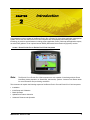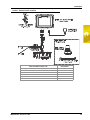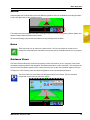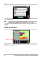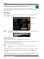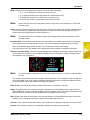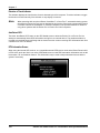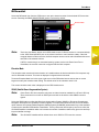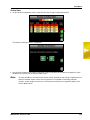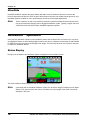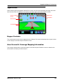
1
Installation & Operation Manual
Envizio Pro™ & Envizio
Pro II™
(Software Version 3.2)
Disclaimer
While every effort has been made to ensure the accuracy of this document,
Raven Industries assumes no responsibility for omissions and errors. Nor is any
liability assumed for damages resulting from the use of information contained
herein.
Raven Industries shall not be responsible or liable for incidental or consequential
damages or a loss of anticipated benefits or profits, work stoppage or loss, or
impairment of data arising out of the use, or inability to use, this system or any of
its components. Raven Industries shall not be held responsible for any
modifications or repairs made outside our facilities, nor damages resulting from
inadequate maintenance of this system.
As with all wireless and satellite signals, several factors may affect the availability
and accuracy of wireless and satellite navigation and correction services (e.g.
GPS, GNSS, SBAS, etc.). Therefore, Raven Industries cannot guarantee the
accuracy, integrity, continuity, or availability of these services and cannot
guarantee the ability to use Raven systems, or products used as components of
systems, which rely upon the reception of these signals or availability of these
services. Raven Industries accepts no responsibility for the use of any of these
signals or services for other than the stated purpose.
Table of Contents
Calibration Reference Sheet .................................................................................................... ix
Unit Definitions and Conversions .............................................................................................. x
Unit of Measure Definitions ................................................................................................. x
Unit of Measure Conversions .............................................................................................. x
Chapter 1
Important Safety Information................................................. 1
Safety Information ..................................................................................................................... 1
Hydraulic Safety .................................................................................................................. 2
Electrical Safety ................................................................................................................... 2
Chapter 2
Introduction............................................................................. 3
Envizio Pro and Envizio Pro II Features .................................................................................... 4
Speed Compensated Product Control and Datalogging ...................................................... 4
On-Screen Guidance ........................................................................................................... 4
Internal DGPS Receiver ...................................................................................................... 5
Optional Features ................................................................................................................ 6
Front Panel ................................................................................................................................ 6
Resistive Touch Screen Technology .................................................................................... 7
Icon Based Operation .......................................................................................................... 7
Rear Panel ................................................................................................................................ 8
Care and Use ............................................................................................................................ 9
Technical Specifications ...................................................................................................... 9
Chapter 3
Installation............................................................................. 11
Overview of the Installation Process ....................................................................................... 11
Kit Contents ....................................................................................................................... 12
Mounting the Field Computer .................................................................................................. 16
Cable Platforms and Connections ........................................................................................... 17
Generation 1 Cable Connections ...................................................................................... 17
Generation 2 Cable Connections ...................................................................................... 19
DGPS Antenna ........................................................................................................................ 20
Installing Optional Equipment .................................................................................................. 22
Boom Sense Wire (Interface Cable Only) ......................................................................... 22
AccuBoom™ ..................................................................................................................... 23
Lightbar ............................................................................................................................. 23
TM-1 Tilt Module ................................................................................................................ 23
SmarTrax™ and SmartSteer™ .......................................................................................... 24
Serial Console ................................................................................................................... 24
AutoBoom™ ...................................................................................................................... 25
CANbus Network Connection ................................................................................................. 25
Manual No. 016-0171-148
i
Table of Contents
Chapter 4
CAN Networking and Diagnostics ...................................... 27
CAN Diagnostics ..................................................................................................................... 30
Node Version Information .................................................................................................. 31
Readdressing the Nodes ................................................................................................... 31
Reset CANbus Defaults ..................................................................................................... 32
Restart CAN Communication ............................................................................................ 32
Additional Node Options .................................................................................................... 32
Programming CANbus Nodes ................................................................................................. 33
CAN Troubleshooting .............................................................................................................. 34
CAN Node Off-line Errors .................................................................................................. 34
Chapter 5
Startup, Initial Setup and Setup Wizards............................ 35
Overview ................................................................................................................................. 35
Initial Setup ........................................................................................................................ 35
Startup ..................................................................................................................................... 36
Touch Screen Calibration .................................................................................................. 37
Initial Setup Wizard ................................................................................................................. 38
Region ............................................................................................................................... 38
Guidance Width ................................................................................................................. 38
Offsets ............................................................................................................................... 39
Control Interface ................................................................................................................ 41
Serial Port Configuration ................................................................................................... 44
Setup Wizards ......................................................................................................................... 44
Setup Wizard Menu ........................................................................................................... 44
Section Setup Wizard .............................................................................................................. 46
Using the Section Setup Wizard ........................................................................................ 46
Product Control Setup Wizard ................................................................................................. 49
Using the Product Control Setup Wizard ........................................................................... 49
AutoBoom™ Setup Wizard ..................................................................................................... 52
Using the AutoBoom™ Setup Wizard ............................................................................... 52
Chapter 6
Basic Operation .................................................................... 53
Overview ................................................................................................................................. 53
Home Screen .......................................................................................................................... 53
GPS Status ........................................................................................................................ 54
Wireless Communications Status ...................................................................................... 55
Information ......................................................................................................................... 55
Closing Jobs and Power Down .......................................................................................... 55
Job Files .................................................................................................................................. 57
Overview ............................................................................................................................ 57
Starting a Job .......................................................................................................................... 57
Setting up a Job ................................................................................................................. 58
ii
Envizio Pro & Envizio Pro II Installation & Operation Manual
Table of Contents
Guidance Screen .................................................................................................................... 64
Guidance Features ............................................................................................................ 64
Using Guidance Patterns .................................................................................................. 65
Product Control Features .................................................................................................. 70
Menu ....................................................................................................................................... 75
Home ................................................................................................................................. 75
Guidance Views ................................................................................................................ 75
A-B Path Tools ................................................................................................................... 76
Field Review Mode ............................................................................................................ 78
Field Review Mode Tools .................................................................................................. 79
Field Boundaries ............................................................................................................... 81
Field Boundary Tools ......................................................................................................... 82
Prescription Maps and Variable Rates .................................................................................... 84
Loading Rx Maps .............................................................................................................. 84
Applying Rx Maps ............................................................................................................. 85
Using Prescription Maps ................................................................................................... 86
System Alarms ........................................................................................................................ 87
Alarms Area ....................................................................................................................... 87
Audible Alarms .................................................................................................................. 88
Chapter 7
Tools Menu ............................................................................ 89
Accessing and Navigating the Tools Menu ............................................................................. 89
Wizard Menu ..................................................................................................................... 90
System Menu .................................................................................................................... 90
GPS Menu ......................................................................................................................... 90
Computer Menu ................................................................................................................. 90
Vehicle Menu ..................................................................................................................... 91
Show All ............................................................................................................................ 91
Navigation ......................................................................................................................... 91
On-Screen Keyboard ......................................................................................................... 92
System Menu .......................................................................................................................... 93
Control Interface ...................................................................................................................... 93
Product Control Options .................................................................................................... 94
Boom Master Options ........................................................................................................ 96
Serial Port Configuration ................................................................................................... 97
CAN Diagnostics ............................................................................................................... 98
Product Control ....................................................................................................................... 98
Application Type ................................................................................................................ 99
Speed ................................................................................................................................ 99
Valve ................................................................................................................................ 101
Calibration Settings ......................................................................................................... 105
Volume and Area Settings ............................................................................................... 109
Feature Settings .............................................................................................................. 110
Alarm Settings ................................................................................................................. 112
Manual No. 016-0171-148
iii
Table of Contents
Section Assignments ....................................................................................................... 114
AccuBoom™ ......................................................................................................................... 114
AutoBoom™ .......................................................................................................................... 114
Steering ................................................................................................................................. 115
GPS Menu ............................................................................................................................. 115
Reverse Sensing ............................................................................................................. 115
GPS Health ...................................................................................................................... 116
Differential ....................................................................................................................... 119
Output .............................................................................................................................. 121
Source ............................................................................................................................. 122
Tilt Sensor ....................................................................................................................... 123
Computer Menu ..................................................................................................................... 124
Display ............................................................................................................................. 124
Region ............................................................................................................................. 126
Updates ........................................................................................................................... 127
File Maintenance ............................................................................................................. 128
Web ................................................................................................................................. 128
Vehicle Menu ......................................................................................................................... 129
Guidance Width ............................................................................................................... 129
Offsets ............................................................................................................................. 130
Boom Sections ................................................................................................................ 132
Profiles ............................................................................................................................. 136
Show All ................................................................................................................................ 137
Chapter 8
Software Updates and File Maintenance.......................... 139
Overview ............................................................................................................................... 139
File Maintenance ................................................................................................................... 140
File Outputs ..................................................................................................................... 140
Performing File Maintenance ........................................................................................... 141
File Structure ......................................................................................................................... 143
ePro Directory .................................................................................................................. 143
Updates ................................................................................................................................. 145
Applying Software Updates ............................................................................................. 146
Chapter 9
Using AccuBoom™ ............................................................ 149
Introduction ............................................................................................................................ 149
CAN Switch Box .............................................................................................................. 149
AccuBoom™ Setup ............................................................................................................... 150
On Override ..................................................................................................................... 150
Section Selection ............................................................................................................. 151
Aggressiveness Factor .................................................................................................... 151
Master Pressure .............................................................................................................. 152
Turn Off Percent .............................................................................................................. 153
iv
Envizio Pro & Envizio Pro II Installation & Operation Manual
Table of Contents
Look Ahead ..................................................................................................................... 153
Enable Zero Speed Override Popup ............................................................................... 153
Enabling AccuBoom™ .......................................................................................................... 154
AccuBoom™ Modes ........................................................................................................ 156
Using Spray Zone Maps ........................................................................................................ 157
Loading a Field Boundary ............................................................................................... 157
AccuBoom™ Mapping Tools ........................................................................................... 158
On-Screen Tools .............................................................................................................. 158
Creating an AccuBoom™ Spray Zone Map .................................................................... 159
AccuBoom™ Spray Zone Map Examples ....................................................................... 162
Chapter 10
Using AutoBoom™............................................................. 165
Introduction ........................................................................................................................... 165
PowerGlide Plus .............................................................................................................. 165
UltraGlide ........................................................................................................................ 166
AutoBoom™ Operation ......................................................................................................... 166
Status Display .................................................................................................................. 166
AutoBoom™ Indicators ................................................................................................... 167
Chapter 11
Troubleshooting ................................................................. 169
Troubleshooting Information .................................................................................................. 169
General Issues ................................................................................................................ 169
Setup Issues .................................................................................................................... 170
Job Issues ....................................................................................................................... 170
Coverage Map Issues ..................................................................................................... 171
Error Messages ..................................................................................................................... 171
Job Error Messages ........................................................................................................ 171
GPS Error Messages ...................................................................................................... 172
CAN Troubleshooting ............................................................................................................ 173
Manual No. 016-0171-148
v
Table of Contents
Appendices
Appendix A Calculating the Calibration Values.................................... 175
Appendix B Testing Cables .................................................................... 187
Appendix C Bogballe Calibrator Zurf Interface .................................... 189
Appendix D Wireless Communications & Remote Service ................. 195
Appendix E Updating CAN Nodes via the Envizio Pro or Envizio Pro II ...
201
Appendix F Reference of Icons ............................................................. 203
vi
Envizio Pro & Envizio Pro II Installation & Operation Manual
Calibration Reference Sheet
Record the settings and calibration values used when programming the field computer and keep this sheet for
future reference or when contacting a service technician.
Circle the setting selected on the field computer for the following options:
UNITS
SPEED
SENSOR
US (Acres)
SI (Hectares)
Turf (1000 Square Feet)
SP1 (Wheel Speed)
CONTROL
TYPE
Liquid Sprayer
VALVE
TYPE
Standard Valve
SP2 (Radar)
Gran 1
(Single belt bed)
Fast Valve
single encoder)
Gran 3
(Split belt bed,
dual encoders)
Spinner RPM
Control
Fast Close Valve
PWM Valve
PWM Close Valve
Gran 2
(Split belt bed,
Write down the calculated calibration values in the spaces provided.
Speed Cal
1.
Boom Widths
(Boom Cal)
Meter Cal
Rate Cal
Volume in
Tank/Bin
Valve Cal
1.
1.
1.
1.
1.
2.
2.
2.
2.
2.
3.
3.
3.
3.
3.
4.
4.
4.
4.
4.
5.
6.
7.
8.
9.
10.
Manual No. 016-0171-148
vii
Calibration Reference Sheet
Unit Definitions and Conversions
Unit of Measure Definitions
Abbreviation
Definition
Abbreviation
Definition
GPM
Gallons per Minute
cm
Centimeters
lit/min
Liters per Minute
dm
Decimeters
dl/min
Deciliters per Minute
m
Meter
PSI
Pounds per Square Inch
MPH
Miles per Hour
kPa
Kilopascal
km
Kilometers
GPA
Gallons per Acre
km/h
Kilometers per Hour
lit/ha
Liters per Hectare
US
Volume per Acre
ml/ha
Milliliters per Hectare
SI
Volume per Hectare
GPK
Gallons per 1,000 Square Feet
TU
Volume per 1,000 Square Feet
mm
Millimeters
[]
Metric Numbers
Unit of Measure Conversions
To convert the METER CAL value into the selected unit of measure, divide the original number printed on the
Flow Meter label by the desired conversion value.
Fluid Ounces Conversion Formula
Liters Conversion Formula
Pounds Conversion Formula
Original METER CAL Number
Original METER CAL Number
Original METER CAL Number
128
3.785
Weight of One Gallon of Product
Liquid
Area
• 1 U.S gallon = 128 fluid ounces
• 1 square meter = 10.764 square feet
• 1 U.S. gallon = 3.785 liters
• 1 hectare = 2.471 acres or 10,000 square meters
• 1 U.S. gallon = 0.83267 imperial gallons
• 1 acre = 0.405 hectares or 43,560 square feet
• 1 U.S. gallon = 8.34 pounds (water)
• 1 square mile = 640 acres or 258.9 hectares
Length
Pressure
• 1 millimeter (mm) = 0.039 inches
• 1 psi = 6.89 kPa
• 1 centimeter (cm) = 0.393 inches
• 1 kPa = 0.145 psi
• 1 meter (m) = 3.281 feet
• 1 kilometer (km) = 0.621 miles
• 1 inch = 25.4 mm or 2.54 cm
• 1 mile = 1.609 km
viii
Envizio Pro and Envizio Pro II Installation and Operation Manual
CHAPTER
1
Important Safety
Information
Chapter1
Safety Information
NOTICE
Read this manual and the operation and safety instructions included with the implement and/or controller
carefully before installing the Envizio Pro or Envizio Pro II field computer.
• Follow all safety information presented within this manual.
• If you require assistance with any portion of the installation or service of Raven equipment, contact a local
Raven dealer for support.
• Follow all safety labels affixed to the system components. Be sure to keep safety labels in good condition
and replace any missing or damaged labels. To obtain replacements for missing or damaged safety labels,
contact a local Raven dealer.
When operating the machine after installing the Envizio Pro or Envizio Pro II field computer, observe the
following safety measures:
•
•
•
•
Be alert and aware of surroundings.
Do not operate the field computer while under the influence of alcohol or an illegal substance.
Remain in the operator’s position in the machine at all times when the field computer is engaged.
Determine and remain a safe working distance from other individuals. The operator is responsible for
disabling the field computer when the safe working distance has been diminished.
• Ensure the field computer is disabled prior to starting any maintenance work on the machine or parts of the
field computer.
• Follow all label instructions for proper chemical mixing, handling and container disposal methods.
DANGER
Thoroughly bleed the nurse tank hose and all other system lines prior to disassembling the flow meter, fittings
and hoses, especially in the case of anhydrous ammonia.
Manual No. 016-0171-148
1
Chapter 1
CAUTION
Hydraulic Safety
• Raven Industries recommends that appropriate protective equipment be worn at all times when working on
any hydraulic system.
• Never attempt to open or work on a hydraulic system with the equipment running. Care should always be
taken when opening a system that has been previously pressurized.
• When disconnecting the hydraulic hoses or purging is required, be aware that the hydraulic fluid may be
extremely hot and under high pressure. Caution must be exercised.
• Any work performed on a hydraulic system must be done in accordance with the machine manufacturer’s
approved maintenance instructions.
• When installing hydraulics or performing diagnostics, maintenance or routine service, ensure that
precautions are taken to prevent any foreign material or contaminants from being introduced into the
machine’s hydraulic system. Objects or materials that are able to bypass the machine’s hydraulic filtration
system will reduce performance and possibly damage the hydraulic valves.
Electrical Safety
• Always verify that the power leads are connected to the correct polarity as marked. Reversing the power
leads could cause severe damage to the equipment.
• Ensure that the power cable is the last cable to be connected.
• Disconnect the Envizio Pro or Envizio Pro II field computer before jump-starting the vehicle.
• Disconnect the Envizio Pro or Envizio Pro II field computer before welding any component of the machine.
2
Envizio Pro and Envizio Pro II Installation and Operation Manual
CHAPTER
2
Introduction
Chapter2
Congratulations on the purchase of the Raven Envizio Pro or Envizio Pro II precision application management
system! The Envizio Pro and Envizio Pro II field computers are multi-purpose tools offering the latest
technology in precision ag with features including product application control, field map and application reports,
as well as field guidance via an optional internal DGPS (Differential Global Positioning System) receiver.
FIGURE 1.
Note:
Raven Envizio Pro or Envizio Pro II Field Computers
The Envizio Pro or Envizio Pro II field computers are also capable of interfacing with the Raven
OmniRow, planter population, or SmartYield, yield monitor, systems. Contact a local Raven dealer
for more information and purchasing assistance.
This document will explain the following aspects of the Raven Envizio Pro and Envizio Pro II field computers:
•
•
•
•
•
Installation
Initial Setup and Calibration
Basic Operation
Updates and Feature Activation
Advanced Features and Operation
Manual No. 016-0171-148
3
Chapter 2
Envizio Pro and Envizio Pro II Features
The following descriptions offer a brief introduction to the capabilities of the Envizio Pro and Envizio Pro II field
computers and some of the optional features available for use with each of these systems.
Speed Compensated Product Control and Datalogging
The Envizio Pro and Envizio Pro II field computers are capable of controlling two products through product
control nodes connected to a CANbus system. The field computer automatically adjusts the application rate of
each product according to the speed of the vehicle, width and status of programmed sections and a
programmed target rate.
With an optional multiple product key, the field computer may control up to four product nodes or control
channels. With the optional variable rate application (VRA) feature, the field computer is also capable of
controlling a single product according to a prescription map. To variable rate multiple products according to
prescription maps, a multiproduct VRA key is also available.
Note:
A single product VRA key is required to successfully authorize the multiple product VRA key.
The Envizio Pro and Envizio Pro II are also capable of monitoring and mapping applications controlled by
another Raven serial console, such as the Raven SCS 440 or 460 consoles, via a serial connection. Variable
rate capabilities of the field computer may also be used with a Raven serial console.
Note:
With the Raven SwitchPro™, the Envizio Pro or Envizio Pro II can replace an existing serial rate
controller to add CANbus product control features using existing control hardware and cabling.
A real-time, as-applied map is displayed on-screen while application information is logged and saved by the
field computer. This job information can then be transferred to a USB flash drive, copied to a home or office PC
and used to create printed reports and coverage maps.
On-Screen Guidance
The Envizio Pro and Envizio Pro II field computers provide on-screen guidance in the form of a Course
Direction Indicator (CDI) and on-screen lightbar. The on-screen navigation features Last Pass, Pivot, Fixed
Contour and Straight Line guidance patterns. In addition, the field computer can output GPS information and
simulated radar speed to an external Raven lightbar. See Chapter 5, Startup, Initial Setup and Setup Wizards,
for more information regarding guidance patterns and the Guidance screen.
4
Envizio Pro and Envizio Pro II Installation and Operation Manual
Introduction
Both the Envizio Pro and Envizio Pro II offer an internal Differential GPS (DGPS) receiver to reduce cab clutter
and simplify transfer of the control system between vehicles for use during various operations such as planting,
spraying and harvesting. A range of receiver options is available to fit into almost any existing system or to
expand DGPS capabilities as field operations grow and change.
Note:
The internal receiver in either the Envizio Pro or Envizio Pro II may be disabled to allow an
optional external receiver, such as a Raven Invicta or Phoenix series or virtually any new or
existing DGPS receiver, to be connected to the system. Refer to Chapter 7, Tools Menu for details
on configuring the field computer to operate with external DGPS receivers and lightbars.
Contact a local Raven dealer for more information about additional options or features available
with the Envizio Pro or Envizio Pro II internal receiver.
Envizio Pro II
The Envizio Pro II features a dual frequency DGPS receiver which includes Satellite Based Augmentation
System (SBAS) correction for use with the Wide Area Augmentation System (WAAS) or European
Geostationary Navigation Overlay Service (EGNOS) as standard options. The NovAtel Gl1de® feature can be
used either in conjunction with a SBAS correction signal as a position smoothing feature or as an independent
correction source for areas with limited SBAS coverage. Both options are available as a standard feature of the
internal dual frequency receiver.
Note:
An optional Global Navigation Satellite System (GLONASS) activation code is available to
enhance the standard GPS satellite constellation.
The Envizio Pro II internal receiver may be upgraded to receive Real-Time Kinematic (RTK) or a Continuously
Operating Reference Station (CORS) network correction services to improve accuracy and repeatability for
precision operations such as planting and strip tilling, or side dressing.
Envizio Pro
The Envizio Pro features an internal DGPS receiver which includes Satellite Based Augmentation System
(SBAS) correction for use with the Wide Area Augmentation System (WAAS) and European Geostationary
Navigation Overlay Service (EGNOS) as standard options. In addition, an Extended Differential (e-Dif)
activation key is also available.
Note:
Envizio Pro consoles without the internal DGPS receiver require an external DGPS receiver for
operation.
Manual No. 016-0171-148
5
2
Internal DGPS Receiver
Chapter 2
Optional Features
Flexibility of the Raven Envizio Pro and Envizio Pro II means that each field computer can be integrated into
many existing Raven product control systems. The field computer can be used to control chemical injection
and anhydrous ammonia applications, planting and harvesting operations or be integrated into an existing
serial control system for mapping and guidance features. The following list is an example of the various Raven
systems or features may be added to the field computer to enhance or modify the control system for a specific
operation:
• AccuBoom™ or AccuRow™ automatic boom or planter section control systems.
• OmniRow™ automatic planter population, singulation and section control system for complete crop input
control.
•
•
•
•
Glide Series AutoBoom™ automatic boom height management systems.
SmarTrax™ or SmartSteer™ for automatic assisted steering systems.
TM-1 Tilt Module offers tilt corrected DGPS guidance over rough and hilly terrain.
Slingshot Field Hub™ for wireless communication and internet access and RTK or CORS GPS corrections
via a cellular wireless service provider.
• SmartYield™ yield monitoring systems.
• SCS Sidekick™ or Sidekick Pro™ direct injection systems for automatic rate control of injected chemicals.
• AccuFlow and AccuFlow HP™ systems for application of anhydrous ammonia (NH3) products.
Contact a local Raven dealer for more information about these and other optional features and components
available for use with the Envizio Pro or Envizio Pro II.
Front Panel
The front panel of the Envizio Pro and Envizio Pro II features a touch screen for operator input, the power
button and also provides convenient access to a USB port for file transfer and software updates.
FIGURE 2.
Envizio Pro and Envizio Pro II User Interface
Power
Touch Screen
USB Port
NOTICE
Failure to close a job before turning the
console’s power off may result in a loss of
information for that job. Make sure to properly
close any open jobs before powering down the
field computer.
6
Envizio Pro and Envizio Pro II Installation and Operation Manual
Introduction
Resistive touch screen technology offers clear visibility across a range of lighting conditions and even in direct
sunlight while the touch screen functionality places menus and options literally at the operator’s finger tips.
CAUTION
Do not use sharp objects, such as ball point
pens, pocket knives, screwdrivers, etc. on the
Envizio Pro or Envizio Pro II display.
Icon Based Operation
Operation of the field computer can be done at a glance due to the icon based interface. Easily recognizable
icons allow the operator to quickly select features or use functions without diverting attention from other
important operations.
File Transfer
Memory within the field computer (512 MB) is used to store current job and application information. Application
information for past jobs should be periodically transferred to a USB flash drive and copied to a home or office
PC to view and more permanently store this information. Use a USB flash drive or “thumb drive,” with at least
512 MB of memory for transferring these files. Storage devices can be purchased at many retail locations or a
local Raven dealer.
FIGURE 3.
Note:
1 GB USB Flash Drive (P/N 524-0002-065)
Install the USB flash drive only when transferring files. Do not start the field computer with a flash
drive connected or leave the “thumb drive” inserted during normal operation.
Manual No. 016-0171-148
7
2
Resistive Touch Screen Technology
Chapter 2
Rear Panel
The following is a brief overview of the connections and ports available on the back of the Envizio Pro and
Envizio Pro II field computers.
The Rear Panel offers an additional USB Port as well as a port for connecting an optional wireless router for
wireless communication. Signal is fed into the internal DGPS receiver through the antenna port located above
the mounting posts.
The main and auxiliary interface connections are also located on the rear panel. These connections will be
used to connect the field computer with the various components and hardware for the specific control system.
FIGURE 4.
Envizio Pro and Envizio Pro II Rear Panel Features and Connectors
USB Port
Ethernet Port
Auxiliary Interface
Connector
Antenna Port
Mounting Posts
Main Interface
Connector
Note:
Envizio Pro field computers without the internal DGPS receiver will not feature an antenna port.
The part number, serial number and revision letter, of the field computer are located on the tags located on the
back of the console. Please have this information available when contacting customer support.
8
Envizio Pro and Envizio Pro II Installation and Operation Manual
Introduction
Care and Use
Refer to the following guidelines for proper care and use of the Envizio Pro and Envizio Pro II field computer.
CAUTION
• Do not apply any type of liquid or glass cleaner directly to the surface of the touch screen. Harsh chemicals
may damage the touch screen. Clean the touch screen and console exterior as needed with a soft cloth
dampened with glass cleaner. Apply the cleaner to the cloth and then wipe the screen gently.
• Do not use any type of pointed or sharp instrument on the touch screen. Only a fingertip or an approved
stylus should be used.
• Do not expose the field computer to precipitation, condensation or other liquids. Store the computer in a dry
environment when not in use.
• Mount the field computer securely and route cables to prevent tripping hazards and to keep the wires from
pinching or breaking.
• When temperatures are expected to be 10° F [-12° C] or lower, remove the field computer from the vehicle
and store it in a climate controlled environment.
• Always remove the field computer from power before jump starting or welding on any component of the
vehicle. Jump starting or welding on the equipment will damage the field computer.
Technical Specifications
Dimensions
Height
Width
Depth
Diagonal
(screen)
Weight
Environmental
Power
Ports
Operating
Temperature
Storage
Temperature
Operating
Voltage
USB
Ethernet
Amp
Plate/Arm
Mounting
Manual No. 016-0171-148
Screws
(Provided)
U.S.
6.26 in.
8.43 in.
3.46 in.
Metric
15.9 cm
21.41 cm
8.79 cm
6.5 in.
16.51 cm
3.68 lbs.
1.67 kg
32° F to 158° F
0° C to 70° C
-4° F to 185° F
-20° C to 85° C
9 VDC to 28 VDC
Reverse Polarity Protected
2 (1 on front, 1 on back)
1 (Back)
2 (Back)
Vesa Plate with
RAM Mounting Arm
10-32 x 1/2” Long
9
Chapter 2
Amp Connector Pin Definitions
Main Amp
Connection
Auxiliary Amp
Connection
1.
Main Amp Connector
Battery Negative
Auxiliary Amp Connector
1.
DGPS Transmit
(Corrections In)
2.
Ext. Switch
3.
CAN Hi
2.
Ext. Switch
4.
CAN Lo
3.
CAN Hi
5.
DGPS Receive
4.
CAN Lo
6.
DGPS Transmit
5.
7.
DGPS CTS
DGPS Receive
(To External Devices)
8.
DGPS RTS
6.
9.
Console Transmit
DGPS Transmit
(To External Devices)
10.
Console Receive
7.
Auxiliary Receive
11.
RS232 Ground
8.
Auxiliary Transmit
12.
Console CTS
9.
Auxiliary CTS
13.
Console RTS
10. DGPS Receive
14.
+ 12 V Ignition
15.
+ 12 V Switched
11. Auxiliary RTS
16.
Battery Positive
12. RS232 Ground
(Corrections In)
13. Not Used
14. Radar Out
10
Envizio Pro and Envizio Pro II Installation and Operation Manual
CHAPTER
3
Installation
Chapter3
Overview of the Installation Process
The following is intended as an overview of the installation process. These instructions cover the basic
installation of the Raven Envizio Pro or Envizio Pro II and necessary hardware. For additional instructions on
installing optional hardware with the field computer, refer to the instructions provided with the optional
component(s). Instructions for building a CAN (Controller Area Network) system can be found in Chapter 4,
CAN Networking and Diagnostics.
Basic installation of the Envizio Pro or Envizio Pro II field computer is as follows:
1.
Review kit contents
2.
Mount the field computer
3.
Mount the DGPS antenna
Manual No. 016-0171-148
11
Chapter 3
Kit Contents
Before proceeding with installation of the Envizio Pro or Envizio Pro II system, review the following contents of
the field computer kit.
Envizio Pro II
TABLE 1. Envizio
Pro II Kit Contents
Envizio Pro II Kits
Envizio Pro II
with SBAS
Components
Envizio Pro II Field
Computer
MBA-6 (Helix) Antenna
Antenna Cable (20’)
Aerial Antenna Mounting
Plate (Optional)
Mounting Kit (includes
Hardware)
Envizio Pro and Envizio
Pro II Installation and
Operation Manual
Envizio Pro and Envizio
Pro II Quick Reference
Guide
Part Number
Envizio Pro II
with RTK
Envizio Pro II
with RTK and
GLONASS
Envizio Pro II
without Antenna
117-5010-001Wa 117-5010-001Ka 117-5010-001KGa 117-5010-001L
063-0173-258
1
1
1
1
063-0172-651
115-0171-787
1
1
1
1
1
1
063-0172-971
1
1
1
117-0171-132
1
1
1
016-0171-148
1
1
1
1
016-0171-149
1
1
1
1
a. The kit letter indicates the included options for internal receiver correction source(s). ‘W’ kits are enabled for SBAS
only; ‘K’ for RTK and ‘KG’ for RTK and GLONASS. ‘L’ kits include an SBAS only enabled receiver.
12
Envizio Pro and Envizio Pro II Installation and Operation Manual
Installation
Envizio Pro II Kit Contents
3
FIGURE 1.
Other Available Components
CAN Switch Box to Envizio Pro Kit
Product Controller Node
RTK GPS/Speed Adapter Cable
(for use with Slingshot RTK subscription)
RTK Authorization Code (OEMV2)
GLONASS Authorization Code (OEMV-1GR)
Population Rate Control Activation Key
Single Product Variable Rate Authorization Key
Manual No. 016-0171-148
Part Number
117-5020-001
063-0173-236
115-0171-972
077-0180-062
077-0180-061
077-0180-058
077-0180-031
13
Chapter 3
Envizio Pro
TABLE 2. Envizio
Pro Kit Contents
Envizio Pro Kits
Envizio Pro with Envizio Pro with
Patch Antenna MBA-3 Antenna
Components
Envizio Pro Field
Computer
Main Interface Cable
Patch Antenna
MBA-3 (Helix) Antenna
Antenna Cable (20’)
Aerial Antenna
Mounting Plate
(Optional)
Mounting Kit (includes
Hardware)
Envizio Pro and Envizio
Pro II Installation and
Operation Manual
Envizio Pro and Envizio
Pro II Quick Reference
Guide
Part Number
063-0172-865
or -939
115-0171-746
063-0172-101
063-0172-480
115-0171-787
Envizio Pro
without GPS
Envizio Pro
without GPS and
Cablinga
117-0171-126
117-0171-137
117-0171-128
117-5010-002
1
1
1
1
1
1
1
1
1
1
063-0172-971
1
117-0171-132
1
1
1
1
016-0171-148
1
1
1
1
016-0171-149
1
1
1
1
a. Interface or Chassis cable platforms sold separately. Refer to the Cable Platforms and Connections section on
page 17 or contact a local Raven dealer for more information.
14
Envizio Pro and Envizio Pro II Installation and Operation Manual
Installation
Envizio Pro Kit Contents
3
FIGURE 2.
Other Available Components
Auxiliary Interface Cable
Helix Antenna Kit
Viper to Viper/Envizio Pro Adaptor Cable
Boom/Speed Node
Single Product Control Node
Combo Interface Cable
Manual No. 016-0171-148
Part Number
115-0171-745
117-0171-141
115-0171-742
063-0172-272
063-0172-373
115-0171-744
15
Chapter 3
Mounting the Field Computer
Refer to the following requirements when selecting a mounting location for the Envizio Pro or Envizio Pro II
field computer:
• The field computer is not weatherproof. Mount the field computer inside of the machine’s cab or driver’s
compartment within easy reach of the driver or operator.
• Securely fasten the RAM mounting arm to a suitable, flat surface. Once mounted, the RAM mounting arm
must provide a stable base for the console and should not impede normal machine operation.
• The field computer should be mounted in a location where it will not be jarred during normal equipment
operation. Keep the computer clear of moving elements within the machine’s cab.
• Route all cables to avoid tripping hazards and protect the cable from kinking or breaking during operation.
To mount the field computer:
Note:
If the CAN Switch Box will be installed with the Envizio Pro or Envizio Pro II field computers, use
the mounting hardware provided with the CAN Switch Box. Refer to the CAN Switch Box
Installation and Operation Guide for mounting instructions.
1.
Mount the circular base of the RAM socket arm (P/N 117-0171-132) securely within the cab of the vehicle.
2.
Using the four mounting posts and supplied hardware, secure the field computer to the square plate of the
RAM mounting arm.
FIGURE 3.
Field Computer Rear Panel
Auxiliary Interface
Connector
Mounting Posts
Main Interface
Connector
16
Envizio Pro and Envizio Pro II Installation and Operation Manual
Installation
Cable Platforms and Connections
Two cable platform options are available for use with the Envizio Pro or Envizio Pro II field computers. Each
platform offers a range of optional features which can be added to the control system at any time.
NOTICE
3
Please review the Raven CANbus Network
Installation Manual for installation instructions
for the specific cable platform being installed
with the field computer prior to beginning
installation. Contact a local Raven dealer for
assistance or to purchase additional
components necessary to set up the CANbus
system.
Generation 1 Cable Connections
Important:Ensure that the Envizio Pro or Envizio Pro II field computer has been properly mounted and all
component cabling is connected properly before connecting the Envizio Pro or Envizio Pro II to power.
FIGURE 4.
Generation 1 Main Interface Cable Connection Diagram
To Field Computer
Main Interface Port
+12V DC
GND
Auxiliary
Power Output
3 Amps Max.
CANbus
Ext. Switch
Console
DGPS
+12V Switched
Manual No. 016-0171-148
17
Chapter 3
1.
Route the conduit with red and white leads to a clean, controlled power source such as a clean power bus
bar or junction box.
2.
Connect the red lead wire to a clean +12V DC power source.
CAUTION
Even when the field computer is powered off,
the computer will draw a small current from the
battery. Connect the red wire to a controlled
power source or, if the machine will not be in
use for an extended period of time, remove
power from the field computer.
To prevent accidental data loss, the red wire
should be connected to a clean power source.
3.
Connect the white wire to ground.
Note:
FIGURE 5.
Do not connect the orange wire to external power. The orange wire is switched power out of the
field computer. When the field computer is powered, +12V DC is applied to the orange wire to
power an external device. If more than 1 amp is required to power a device connected to the
orange wire, install a relay to switch the higher currents.
Relay (P/N 415-1001-009) Terminals
Batt +
Batt -
12V Switched
to Node Power
To 12V Switched Orange
Wire Key Switch
18
Envizio Pro and Envizio Pro II Installation and Operation Manual
Installation
Generation 2 Cable Connections
The chassis cable platform requires the following components:
• Machine specific chassis cable
• Envizio Pro or Envizio Pro II chassis interface cable (P/N 115-0171-926)
• CAN Switch Box kit (P/N 117-5020-001)
FIGURE 6.
Note:
Refer to the Raven CANbus Network Installation Manual for additional cabling information for the
generation 2 cable platform.
Generation 2 Cable Connection Diagram
3
Note:
The CAN Switch Box is not used with the OmniRow system.
Manual No. 016-0171-148
19
Chapter 3
Chassis Interface Cable and CAN Switch Box Connection
Note:
The CAN Switch Box and switch box mounting bracket should be mounted to the Envizio Pro or
Envizio Pro II field computer prior to beginning the following procedure. Refer to the CAN Switch
Box Installation and Operation Guide for detailed instructions.
1.
Locate the single round connector labeled ‘To Chassis or SmarTrax Tee Cable’ on the Envizio Pro/Viper Pro
chassis interface cable (P/N 115-0171-926).
2.
Insert this connector into the ‘To Cab Cable’ on the chassis cable installed on the vehicle. Thread the
connectors together to secure the connection.
3.
Route the end of the cable with two round connectors to the back of the Envizio Pro or Envizio Pro II and
connect to the main and auxiliary ports.
4.
Connect the 2-pin Deutsch connector labeled ‘Switched Power Output’ to the back of the CAN Switch Box.
5.
Connect the 4-pin Deutsch connector labeled ‘CANbus’ to the back of the CAN Switch Box.
6.
Connect the 3-pin round connector labeled ‘GPS Speed Out’ to the back of the CAN Switch Box.
Note:
If the chassis interface cable (P/N 115-0171-926) is installed and the internal DGPS receiver will
be used for DGPS reception, the ‘Internal GPS Receiver Ouput’ and ‘GPS Receiver/DGPS’ port
connectors must be connected together.
DGPS Antenna
Note:
To enable the guidance capabilities of the field computer, DGPS signal must be supplied by one of
the following:
• The internal DGPS receiver
• An optional external receiver capable of outputting messages at a minimum of 10 Hz.
For more information on configuring the Envizio Pro or Envizio Pro II field computers for one of the
above options, see Chapter 7, Tools Menu.
With the internal receiver, the Envizio Pro or Envizio Pro II only requires a connection to a DGPS antenna in
order to create application maps. To ensure the best possible signal reception, the following recommendations
should be considered when selecting the DGPS antenna mounting position.
• Mount the DGPS antenna to the tallest point of the vehicle (usually the vehicle’s cab) using the standard
magnet mount.
• Make sure that the DGPS antenna has a clear 360° view of the sky.
• Mount the DGPS antenna at least of 36” [92 cm] from other antennas (e.g. radio, cellular, etc.) to avoid
signal interference.
• The simplest setup is achieved by mounting the antenna on the center-line of the vehicle.
Aerial Antenna Mounting Plate (Optional)
An optional aerial antenna mounting plate (P/N 063-0172-971) is included with field computers featuring a helix
style antenna. If no suitable magnetic mounting location exists on the vehicle, this mounting plate may be
affixed to the tallest point of the vehicle to provide a magnetic surface for mounting the GPS antenna.
20
Envizio Pro and Envizio Pro II Installation and Operation Manual
Installation
Connecting the Antenna to the Internal DGPS Receiver
1.
(Helix antennas only) Connect the antenna cable (P/N 115-0171-787) to the antenna.
2.
Route the cable into the cab and connect to the antenna port on the back of the field computer.
FIGURE 7.
Antenna Port for Internal DGPS Receiver
3
Antenna Port
Note:
3.
Envizio Pro consoles without the internal DGPS receiver will not feature the antenna port.
If the chassis interface cable (P/N 115-0171-926) is installed and the internal DGPS receiver will be used for
DGPS reception, the ‘Internal GPS Receiver Output’ and ‘GPS Receiver/DGPS’ port connectors must be
connected together.
FIGURE 8.
Envizio Pro and Envizio Pro II Antenna Options for Internal DGPS Receivers
MBA-3 Antenna Kit
117-0171-141
Patch Antenna
063-0172-101
MBA-3
Helix Antenna
063-0172-480
20’ TNC (M) - BNC (M) Cable
115-0171-787
Note:
MBA-6
Helix Antenna
063-0172-651
20’ TNC (M) - BNC (M) Cable
1063-0173-317
The Envizio Pro II requires a MBA-6 helix antenna (P/N 063-0172-651) for use of RTK or CORS
corrections with the internal GPS receiver.
Connecting External DGPS Receiver Systems
1.
Follow installation instructions included with any optional or additional external DGPS components before
connecting to the field computer or related cabling.
2.
Signal from an external DGPS receiver must be routed into the field computer via the connector labeled
‘GPS Receiver’ or ‘DGPS’ on the main interface cable (P/N 115-0171-746) or chassis interface cable (P/N
115-0171-926).
3.
For help with setting up the field computer to use the signal from an external receiver, refer to Chapter 7,
Tools Menu.
Manual No. 016-0171-148
21
Chapter 3
Installing Optional Equipment
The following sections offer descriptions of optional hardware or configurations in which the Envizio Pro or
Envizio Pro II is capable of operating.
Boom Sense Wire (Interface Cable Only)
The boom sense wire can be connected to the master switch functions of the machine to allow seamless
operation of vehicle master on/off and the field computer mapping feature.
If the boom sense wire is properly connected, the vehicle master on/off switch also toggles the product
coverage mapping based on a +12V signal detected on this wire. Connect the spade connector on the main
interface cable (P/N 115-0171-746) labeled “Ext. Switch” (external switch) to the machine master switch.
Contact the machine manufacturer for more information on connecting the boom sense wire on the specific
machine.
FIGURE 9.
Main Interface Cable (P/N 115-0171-746) Boom Sense Wire Connection
Boom Sense Wire
22
Envizio Pro and Envizio Pro II Installation and Operation Manual
Installation
AccuBoom™
Refer to the machine specific installation materials for instructions on installing AccuBoom on the machine.
Note:
When used with a CAN product control system, AccuBoom requires a boom/speed node with
program D or newer for proper AccuBoom functionality.
AccuBoom™ Master Switch
To enable the AccuBoom master switch, connect the orange wire with white stripe on the AccuBoom node
harness to the machine master switch. Contact a local Raven dealer for more information on part numbers and
availability of the AccuBoom feature for the specific sprayer model.
Contact the machine’s manufacturer for more information on connecting this feature.
Lightbar
Envizio Pro and Envizio Pro II field computers are capable of interfacing with an external Raven lightbar
through the auxiliary interface cable (P/N 115-0171-745) or the chassis interface cable (P/N 115-0171-926).
If an external lightbar is desired, follow the installation instructions provided with the lightbar before connecting
the lightbar to the field computer. Once installation of the lightbar is complete, connect the lightbar cable to the
serial connector labeled ‘COM 3’ on the appropriate interface cable. See Chapter 7, Tools Menu, for
information on configuring the field computer to send messages to the external lightbar.
TM-1 Tilt Module
GPS receivers output position information relative to the position of the DGPS antenna. Most often, the
antenna is mounted on the top of the machine which means the GPS location is only accurate when the
machine is on level ground. On uneven terrain, such as side hills, the actual ground position may differ from
the location of the GPS antenna.
FIGURE 10.
Reported GPS Position Error Due to Side Hill
Tilt
Angle
Error
ST ARLI
NK
Antenn
a
Height
Error
The Raven TM-1 Tilt Module compensates for any tilt of the vehicle from a level field condition. To supply tilt
compensated GPS signal, the Raven TM-1 Tilt Sensor receives a raw DGPS signal from the DGPS receiver
and outputs a tilt corrected signal to guidance devices or controllers.
Manual No. 016-0171-148
23
3
The AccuBoom master switch option will allow AccuBoom to toggle coverage mapping and section information
as reported by the AccuBoom node.
Chapter 3
If connected directly to the ‘DGPS’ connector on the main interface cable (P/N 115-0171-746) or chassis
interface cable (P/N 115-0171-926), the field computer may be used to configure the TM-1. Refer to the TM-1
Tilt Module Installation and Operation manual for details and installation diagrams for installing the Tilt Module
with the Envizio Pro or Envizio Pro II field computer.
Note:
See the System Menu section on page 93 for information on setting up the TM-1 using the field
computer.
When routing tilt corrected signal through a SmarTrax controller and back into the Envizio Pro or
Envizio Pro II, the TM-1 will need to be calibrated through the SmarTrax controller rather than the
field computer. See the SmarTrax Quick Start Guide or Operator’s Manual for more details on
setting up and operating the TM-1 with a SmarTrax controller.
SmarTrax™ and SmartSteer™
Envizio Pro and Envizio Pro II field computers are also capable of operating with the optional SmarTrax or
SmartSteer automated steering systems.
GPS signal is routed into the SmarTrax controller and then fed into the field computer via the ‘DGPS’ connector
on the Envizio Pro main interface cable (P/N 115-0171-746) or chassis interface cable (P/N 115-0171-926).
When the SmarTrax or SmartSteer system is engaged, the automated steering system controls the vehicle
steering system, either hydraulically or by mechanically turning the steering wheel, to guide the vehicle along a
guidance path displayed on the field computer Guidance screen. See the Source section on page 122 to
configure the Envizio Pro or Envizio Pro II to use an optional SmarTrax or SmartSteer system.
Serial Console
FIGURE 11.
24
Envizio Pro Interface Cable Platform with Serial Control Console
Envizio Pro and Envizio Pro II Installation and Operation Manual
Installation
The Envizio Pro or Envizio Pro II may be connected to a Raven serial control console via a serial port
connection. In this configuration, the field computer is primarily used for the datalogging, mapping and
guidance capabilities.
Note:
If connected to a serial control console, the field computer does not require a separate boom/
speed or product control node. An AccuBoom, AutoBoom or SmarTrax node still may be
connected to the field computer.
Use one of the following Raven RS-232 cables to connect the serial port on the back of the serial control
console to the connector labeled ‘Console’ on the Envizio Pro main interface cable (P/N 115-0171-746).
Description
RS-232 cable - 3 ft.
RS-232 cable - 10 ft.
Note:
Part Number
115-0171-040
115-0159-822
Use only a Raven RS-232 communication cable between the field computer and the serial control
console. Contact a local Raven dealer for purchasing and more information.
See Chapter 7, Tools Menu, to setup the field computer for the serial console connection.
AutoBoom™
Follow the machine or implement specific installation manual to install the AutoBoom hydraulic valve and
hoses.
NOTICE
Read all safety requirements and precautions in
the machine specific installation manual prior to
operating a machine equipped with the
AutoBoom feature. Failure to follow safety
precautions may lead to damage to equipment,
injury or death.
CANbus Network Connection
Envizio Pro and Envizio Pro II field computers are capable of controlling up to four product nodes or control
channels (with required activation keys) on a CANbus system. The field computer will automatically scan for
CAN product control, planter control, AccuBoom, AutoBoom, SmarTrax, boom sense and speed nodes
connected through the CAN connection.
See Chapter 4, CAN Networking and Diagnostics, for additional information.
Manual No. 016-0171-148
25
Chapter 3
26
Envizio Pro and Envizio Pro II Installation and Operation Manual
CHAPTER
4
CAN Networking and
Diagnostics
Chapter4
A Controller Area Network, or CAN, system is a high-integrity serial data communications bus that operates at
a data rate of 250 kilobits per second for real-time control applications and uses special cables and terminators
for operation. The CAN protocol has excellent error detection and confinement capabilities, making it very
suitable and reliable for agricultural applications.
CAN systems allow products to be added to a control system at any time. Up to four product control nodes or
control channels can be connected to the Envizio Pro or Envizio Pro II control system for any combination of
liquid, granular, chemical injection or spinner control applications.
The diagrams in this chapter show different hardware configurations for use with the Envizio Pro or Envizio Pro
II field computers. Some diagrams show optional features which may not apply to each system. These features
and components are not required for CAN operation and optional features and cables may be ignored during a
basic installation.
The following diagrams are provided as examples of an Envizio Pro or Envizio Pro II field computer control
network.
NOTICE
Refer to the Raven CANbus Network
Installation Manual for installation information
for individual CANbus control components. Be
sure each component is properly mounted and
cables are connected prior to powering the field
computer.
Manual No. 016-0171-148
27
Chapter 4
FIGURE 1.
28
Envizio Pro Single Product CAN Control System
Envizio Pro and Envizio Pro II Installation and Operation Manual
CAN Networking and Diagnostics
Envizio Pro Dual Product (Liquid/Granular) CAN Control System
4
FIGURE 2.
Manual No. 016-0171-148
29
Chapter 4
CAN Diagnostics
The field computer must be able to communicate with the CANbus system when monitoring or controlling
product application. If configured as a CAN control console, the Envizio Pro or Envizio Pro II should
automatically establish communication with the boom/speed node, the AccuBoom, AutoBoom or SmarTrax
Terrain Compensation nodes (if installed) and up to four product control nodes via the CANbus.
Note:
Product nodes may need to be readdressed prior to detecting each node on the CANbus. See the
Readdressing the Nodes section on page 31 for detailed instructions on readdressing the product
nodes.
Contact a local Raven dealer for more information on required activation keys for controlling up to
four products using the Envizio Pro and Envizio Pro II field computers.
To view a list of nodes currently detected on the CANbus network:
1.
Select the Information icon in the upper, right corner of the Home screen.
2.
Touch the
icon on the About Envizio Pro screen to display the CAN Diagnostics screen.
Readdress Nodes
Reset Defaults
Retry CAN
Communication
Update Nodes
Note:
30
Node Hardware
Information
Select Channels
If a product is not found, troubleshoot the node to determine why the field computer cannot
communicate with the node. See the CAN Troubleshooting section on page 34 for more
information about CAN communication failures.
Envizio Pro and Envizio Pro II Installation and Operation Manual
CAN Networking and Diagnostics
Node Version Information
The CAN Diagnostics screen displays the software version, software revision and program number of each
node detected on the CANbus.
1.20 (143)
Software
Version
Software
Revision
Program
Number
Readdressing the Nodes
If the field computer is unable to detect a CANbus node on startup, troubleshoot the CANbus and the node
(see the CAN Troubleshooting section on page 34) and then readdress the CANbus:
Note:
Only product nodes need to be addressed (single product, dual product, motor control, etc.).
Select the Information icon in the upper, right corner of the Home screen.
2.
Touch the
icon on the About Envizio Pro screen to display the CAN Diagnostics screen.
3.
Touch the
button to begin readdressing the product control nodes.
4.
When prompted to cycle power on the first product node, disconnect the logic power from the product node
to be controlled as Product 1. After approximately 3 seconds, reconnect the node’s logic power. The field
computer should have recognized the node as ‘Product 1.’
5.
If additional product nodes are installed in the CANbus, repeat step 4 to readdress the remaining product
nodes as necessary
6.
Touch the Accept icon to finish readdressing the product nodes.
4
1.
Manual No. 016-0171-148
31
Chapter 4
Reset CANbus Defaults
NOTICE
Resetting system defaults will clear all
calibration information from any product control
nodes. Before resetting system defaults, it is
recommended to write down any necessary
calibration information that may help to
recalibrate the system.
To reset all product control nodes on the system:
1.
From the Home screen, touch the Tools Menu icon and access the Control Interface screen from the
System menu.
2.
Touch the
icon along the right side of the screen to access the CAN Diagnostics screen.
3.
Touch the
button to clear all product node or control channel settings. Use the Calibration Reference
Sheet section on page ix if necessary to record the required calibration values for system operation. To help
record additional settings for each node, step through or review the Product Control Setup Wizard section
on page 49.
4.
Touch the Accept icon to proceed with the system reset or select the Cancel icon to return to the CAN
Diagnostics screen without resetting the CANbus system.
Note:
Refer to the Product Control Setup Wizard section on page 49 for assistance recalibrating the
product control nodes.
Restart CAN Communication
If a node currently connected to the CANbus system is not displayed on the CAN Diagnostics screen, touch the
button to start the CAN system. If the node still does not appear on the CAN Diagnostics screen, the
CANbus system may need to be readdressed. Review the Readdressing the Nodes section on page 31 for
instructions on readdressing the product nodes.
Additional Node Options
The following features or options may also be available via the CAN Diagnostics screen:
Select Control Channels
The Raven product controller node is capable of providing up to four product control channels on
an Envizio Pro or Envizio Pro II control system. By default, the product controller will make two
control channels available to the field computer for controlling product application.
Select one of the product controller node channels and select the Select Channels icon (shown to
the left) to set the number of control channels available via the node.
Note:
32
The Select Channels icon will display the current number of channels which the node is providing
to the field computer. Each control channel must be configured separately via the Tools Menu.
Envizio Pro and Envizio Pro II Installation and Operation Manual
CAN Networking and Diagnostics
Hardware Summary
Select a node from the list displayed on the CAN Diagnostics screen and touch this icon to view
detailed node hardware information if available. The hardware summary screen provides node
operating information that may be helpful when contacting technical support or while
troubleshooting CAN communication issues.
Note:
If the node is not capable of providing hardware information, the Hardware Summary screen will
display “N/A” for the unavailable diagnostic values.
Update CAN Nodes
Programming CANbus Nodes
Regardless of cabling platform or field computer, the CAN nodes are programmed using the Tools Menu. The
boom/speed (or combo node) is programmed via the Vehicle and System menus. Product, AccuBoom,
AutoBoom and SmarTrax nodes, if installed, are programmed through the System menu.
See Chapter 7, Tools Menu, for information on programming CAN product nodes. See Chapter 9, Using
AccuBoom™, for information on programming AccuBoom and Chapter 10, Using AutoBoom™, for an
overview of the AutoBoom system on the Envizio Pro or Envizio Pro II field computers.
Manual No. 016-0171-148
33
4
Select a node from the list displayed on the CAN Diagnostics screen and touch this icon to update
the node firmware via the CANbus network using the field computer. Refer to Appendix E,
Updating CAN Nodes via the Envizio Pro or Envizio Pro II, for additional assistance performing a
node update using the field computer.
Chapter 4
CAN Troubleshooting
Although the control algorithm is located within the CAN node, all of the same troubleshooting techniques that
are used in a traditional hard-wired or serial control systems still apply to a CAN system and the behavior of the
system remains the same. Flow and speed sensors, as well as the control valve and boom valves, are used in
the same fashion.
CAN Node Off-line Errors
Occasional reports have been received on Raven consoles sporadically losing communication with one or
more CAN nodes. The most likely causes for this problem are:
1.
Corroded and/or open connections in the circuit.
2.
Computer and/or CAN node logic power and grounds connected to a “dirty” power source (dirty power is
defined as any circuit with a variable load that exceeds 1 ampere). This is especially true of circuits loaded
by electrical coils.
3.
Computer and/or nodes connected to different power and/or ground sources. This can result in components
operating at different voltage planes.
Below are some common causes for communication failures:
Issue
Possible Cause
Solution
• The node is not connected to • Connect the node and re-initialize the field computer to read
the CANbus
the product node.
• Connect the clean power - 16 gauge red wire and high current
power - 12 gauge red wire from the product node to a 12V DC
• Node is not properly powered
power source that is capable of supplying power to all nodes
connected to the CANbus system
• Node is not properly
grounded
• Connect the clean ground - 16 gauge white wire and the high
current ground - 12 gauge white wire to a good, quality ground
source. Raven recommends grounding the wires to the
negative terminal of the battery.
• The boom/speed node share
• Make sure that each node has a separate power and ground
power and ground
connection.
connections
CANbus cannot
read the product
node
• Make sure that both ends of the CANbus system are properly
terminated. Refer to the Raven CANbus Network Installation
• CANbus ends not terminated
Manual for information on properly terminating the CANbus
network.
• Corroded pins in CANbus
connections
• Check CANbus cable connectors for any highly corroded pins.
• Ensure dielectric grease has been applied to all cable
connections exposed to weather and field conditions.
• Check CANbus cable connectors for any corroded pins.
• Moisture in connection
• Connectors not seated
properly
34
• Ensure dielectric grease has been applied to all cable
connections exposed to weather and field conditions.
• Check that all CANbus cable connectors are inserted fully
(until the locking tab is engaged).
• Be sure to remove any moisture in connections which were
not properly seated. Check for corroded pins and apply
dielectric grease when reconnecting CANbus cables.
Envizio Pro and Envizio Pro II Installation and Operation Manual
CHAPTER
5
Startup, Initial Setup
and Setup Wizards
Chapter5
Overview
The first time the Envizio Pro or Envizio Pro II field computer is powered up, the field computer will require
some information about the machine and the type of applications, products and additional features connected
to the system. The field computer gathers this information through a setup wizard which will prompt the user to
input the required information to setup the computer for the first time.
Initial Setup
The initial setup wizard will automatically begin when the console is powered up for the first time. This process
should only take a few minutes to complete and is only required during the initial power up sequence.
Note:
If the field computer displays an alert regarding an authorization code after starting the console,
contact a local Raven dealer or the Raven Technical Support Center for assistance. Refer to the
Special Features Registration section on page 127 for instructions on entering the authorization
code.
The initial setup wizard will require the following vehicle information:
•
•
•
•
Desired language and display units for operation.
Guidance width (width of boom or implement without fence row nozzles, foam markers, etc.).
Antenna offsets (left/right, fore/aft) and height.
Whether the field computer will be interfacing with a CAN system, another Raven serial console or none of
these systems.
• How the boom master switch operation should be monitored by the field computer.
Other Required Wizards
Additional wizards may be required during the initial startup depending upon the settings and selections
entered during this process. Detailed descriptions of those wizards are also available in this chapter.
Manual No. 016-0171-148
35
Chapter 5
Launching Wizards
To start the setup wizards after the initial power up has been completed, select the wizard icon in the upper left
corner of the Tools menu.
See the Setup Wizards section on page 44 for a detailed description of the other available wizards.
Startup
The Envizio Pro or Envizio Pro II field computer will take several seconds to power up and initialize the user
interface, DGPS reception and the other features of the system.
During startup, the field computer will display the following prompt.
Ignore this prompt to allow the field computer to startup normally.
Note:
36
To launch the touch screen calibration wizard, touch the screen while this prompt is displayed.
Envizio Pro and Envizio Pro II Installation and Operation Manual
Startup, Initial Setup and Setup Wizards
Touch Screen Calibration
The touch screen displays an arrow in the location last selected. If the arrow does not appear in the location
previously touched, the touch screen may need to be recalibrated.
Note:
The Envizio Pro or Envizio Pro II does not require re-calibration of the touch screen every time the
console is powered on. Use this procedure only if you are having difficulty with the user interface
or the cursor appears in a different location than selected on the touch screen.
To Re-calibrate the Touch Screen
When prompted, touch the screen to begin re-calibration of the touch screen.
Note:
The operator has approximately 7 seconds to touch the screen to begin the calibration process.
2.
The first calibration target will appear. Touch the center of the target.
3.
Each of the four following targets will require the operator to touch and hold the center of the target for
approximately two seconds. When prompted, release to display the next calibration target.
4.
After all of the calibration targets have been completed, test the touch screen calibration by touching in
various areas of the screen.
5.
Two options will appear in the lower left corner of the screen:
5
1.
• Touch ‘Accept’ to apply the screen re-calibration and start the field computer.
• Touch ‘Cancel’ to reject the screen calibration. The field computer will re-apply the previous
touch screen calibration before starting the computer.
Manual No. 016-0171-148
37
Chapter 5
Initial Setup Wizard
The initial setup wizard will automatically begin when the Envizio Pro or Envizio Pro II is powered up for the first
time. This wizard will step through the initial settings and calibration values required for operation of the field
computer and control system. This process should only take a few minutes to complete and is only required
during the initial power up sequence.
Any values or settings programmed during the initial setup wizard can be modified or refined later through the
Tools Menu.
Note:
Many of the values entered in the initial setup wizard are required for guidance and/or product
control features of the control system. Therefore, the more accurate these values can be
measured, the more accurate the control system will be.
The following sections may help complete the initial setup wizard. To confirm the settings displayed on a
screen and proceed with the initial setup wizard, touch the ‘Next’ or ‘Accept’ icons. If available, the ‘Previous’
icon will step back to the previous Setup screen.
Previous
Next
Accept
Region
The first screen displayed during the initial setup wizard is the Region screen. Select the preferred language
and units for display on the field computer.
• Metric - centimeters, liters, hectares, kilometers per hour
• English - inches, gallons, acres, miles per hour
• Turf Units - inches, gallons per 1000 square feet, miles per hour
Select the desired units of pressure to be used with an optional Glide Series AutoBoom system.
• kilo Pascals
• pounds per square inch
Time Zone Settings
Touch the Time Zone icon in the upper right corner to view and modify time zone settings. The default
selections will allow the field computer to automatically configure the time zone and daylight savings for the
region of operation. To manually change the time zone, select the ‘Manual Time Zone’ option and enter the
UTC (Coordinated Universal Time) offset hours for the local time zone.
Guidance Width
The guidance width should be entered as the width of the boom, implement or header which actually
completes an operation while the vehicle drives a swath. For example, the measured guidance width for a
sprayer boom should not include fence row nozzles or foam markers and the guidance width of a combine
header should be the cutting surface, not the overall header width.
Use the on-screen keypad to enter the guidance width in inches (English) or centimeters (Metric) for the boom,
implement or header.
38
Envizio Pro and Envizio Pro II Installation and Operation Manual
Startup, Initial Setup and Setup Wizards
Offsets
The antenna offset is used to calibrate the field
computer for the relative location of the center of the
boom or implement with respect to the GPS antenna.
Note:
The field computer will not recognize a
negative value for any of the antenna offset
values. Be sure to enter positive values for
each offset setting. All negative values
entered will be reset to ‘0’.
The Raven Offsets Setup screen displays the currently
calibrated values for the following antenna offsets:
• Fore/Aft
• Left/Right
• Height
Fore or Aft Offset
The fore/aft offset is the distance of the boom or implement in front or behind the GPS antenna.
Note:
The fore/aft offset must be measured perpendicular to the boom or implement width. See Figure 1
below.
1.
Touch the current fore/aft value displayed on the Raven Offsets Setup screen.
2.
Use the keypad to enter the measured fore/aft value in inches (U.S.) or centimeters (Metric).
3.
If the boom or implement is in front of the GPS antenna, select the ‘Implement in Front’ option.
FIGURE 1.
5
To set the fore/aft value:
Example of the Fore/Aft Measurement
DGPS Antenna
Center of Boom/
Implement
Manual No. 016-0171-148
Fore/Aft
Measurement
39
Chapter 5
Left or Right Offset
The left/right offset is the distance from the GPS antenna to the center line of the boom or implement.
Note:
The left/right offset must be measured parallel to the boom or implement width. See Figure 2
below.
To set the left/right value:
1.
Touch the current left/right value displayed on the Raven Offsets Setup screen.
2.
Use the keypad to enter the measured left/right value in inches (U.S.) or centimeters (Metric).
3.
If the center line of the boom or implement is to the left of the GPS antenna, select the ‘Left of Center’
option.
FIGURE 2.
Example of Left/Right Measurement
DGPS Antenna
Left/Right
Measurement
Center of Boom/
Implement
Height
The height value is the measurement from the ground to the bottom of the GPS antenna.
To set the Height value:
1.
Touch the current height value displayed on the Raven Offsets Setup screen.
2.
Use the keypad to enter the measured height of the antenna in inches (U.S.) or centimeters (Metric).
40
Envizio Pro and Envizio Pro II Installation and Operation Manual
Startup, Initial Setup and Setup Wizards
Control Interface
The multi-functional capabilities of the Envizio Pro and Envizio Pro II mean that the field computers are
capable of interfacing with several different product application systems. To function properly in any one of the
possible systems, the field computer must be setup to receive application information from the correct source.
The following sections describe the options displayed on the Control Interface screen and will help with
selecting the appropriate product control and boom master options for the system.
Note:
Once initial startup and calibration is completed, the Control Interface screen is available within the
Tools menu. See Chapter 7, Tools Menu, for more information about the Tools menu.
When the control interface options are set correctly for the system, touch the ‘Next’ icon to display
the Setup Wizard Menu. One or more additional wizards may be required before the initial setup of
the field computer is complete.
Product Control Options
5
The product control options configure the Envizio Pro or Envizio Pro II to monitor or control product application,
coverage or harvest operations. The following options are available for use on the field computer:
• None - Select ‘None’ if the field computer will not be controlling product application or interfacing with a
Raven console through a serial connection.
• Raven Serial Console - This option is used when the field computer is connected to another Raven product
control console, such as a Raven SCS 440/460, via a serial connection.
In this configuration, the field computer will monitor and display application information sent from the Raven
console.
• Raven CAN Console - This option is used when another control console will be used to control product
nodes on the CANbus.
In this configuration, the Envizio Pro or Envizio Pro II will only monitor and display application information
sent over the CANbus.
Note:
Control inputs must be made via the CAN control console. The Envizio Pro or Envizio Pro II
product control features will not be available during application.
Manual No. 016-0171-148
41
Chapter 5
• CAN Sprayer/Spreader Control - Select ‘CAN Sprayer/Spreader Control’ if the field computer will be used to
control two products, or up to four products if the required activation key is entered, via a CANbus system.
Note:
If more than one product node has been installed with the field computer, touch the
CAN Diagnostics icon (shown right) and review the CAN Diagnostics section on
page 30 to re-address the product nodes.
Select the “AccuBoom Combo Node” option if an AccuBoom system is installed and an
AccuBoom combo node is present on the CANbus. The ’Use as Boom/Speed AccuBoom Combo Node’
option will only appear if the ‘AccuBoom Combo Node’ option is selected. Select this option to use the
AccuBoom combo node as the boom/speed node. If this option is selected, a separate boom/speed node is
not required for the CANbus system.
• CAN AccuRow Only - Select ‘CAN AccuRow Only’ if the field computer will be used to provide automatic
section control for a multi-section planter implement. Refer to the AccuRow Calibration & Operation Manual
for more information.
• CAN Planter Control - Select the ‘CAN Planter Control’ option if the field computer will be used with a Raven
OmniRow system to provide seed population rate control and AccuRow automatic row or section shut off.
Refer to the OmniRow Calibration & Operation Manual for more information.
• Yield Monitor - Select ‘Yield Monitor’ if the field computer will be used with the Raven SmartYield system to
monitor and log harvest data. Refer to the SmartYield Calibration & Operation Manual for more information.
• Bogballe Calibrator Zurf - Select the ‘Bogballe Calibrator Zurf’ option if the field computer will be used in
conjunction with the Bogballe Calibrator Zurf console for guidance and monitoring of product applications
using Bogballe weight systems. Refer to Appendix C, Bogballe Calibrator Zurf Interface, for additional
information.
Boom Master Options
The boom master options allow the operator to setup the preferred method to toggle recording of the coverage
map. Depending upon the control system, the following options may be available to configure the input of the
boom master switch used with the field computer.
42
Envizio Pro and Envizio Pro II Installation and Operation Manual
Startup, Initial Setup and Setup Wizards
None/Raven Serial Console
The following options are available if the product control option is set to either ‘None’ or ‘Raven Serial
Console’:
• Envizio Pro Boom Sense Wire - Select this option if the boom sense wire has been connected as instructed
in the Boom Sense Wire (Interface Cable Only) section on page 22.
• On-Screen Vehicle Arrow - This option allows the operator to touch the Vehicle Arrow
(shown to the right) displayed on the Guidance screen to toggle the coverage history on or
off.
• AccuBoom Master Switch - If an optional AccuBoom system has been installed with the
control system, select the AccuBoom master switch option to create the coverage map based upon the
section information reported by the AccuBoom node.
CAN Options
If CAN Sprayer/Spreader Control is selected as the product control option, the list of boom master options is
replaced by CAN AccuBoom options.
• Do not select the ‘AccuBoom Combo Node’ option if an optional AccuBoom system has not been installed
on the CANbus.
• AccuBoom Combo Node - If an AccuBoom system is installed and an AccuBoom combo node is present on
the CANbus, select this option. The following option will appear in the AccuBoom Options list.
• Use as Boom/Speed AccuBoom Combo Node - This option will only appear if the ‘AccuBoom Combo Node’
option is selected. Select this option to use the AccuBoom combo node as the boom/speed node. If this
option is selected, a separate boom/speed node is not required for the CANbus system.
• Reverse Sensing - Select this option to configure the field computer to detect when the vehicle direction is
reversed.
• On-Screen Vehicle Arrow - This option allows the operator to touch the Vehicle Arrow
(shown to the right) displayed on the Guidance screen to toggle the coverage history on or
off.
• AccuRow Master Switch - If an optional AccuRow system has been installed with the field computer, select
the AccuRow master switch option to create the coverage map based upon the section information reported
by the AccuRow node.
Manual No. 016-0171-148
43
5
If the ‘CAN AccuRow Only’ or ‘CAN Planter Control’ options are selected, the boom master options displays
the available options for CAN planter control.
Chapter 5
Serial Port Configuration
Touch the Serial Port icon in the upper right corner of the Control Interface screen to set up a serial device.
• None - Select this option if no serial device is connected to the field computer.
• Lightbar Interface - Select this option to allow the field computer to control an external lightbar connected to
the connector labeled ‘COM3/Lightbar’ on the auxiliary interface cable (P/N 115-0171-745) or chassis
interface cable (P/N 115-0171-926).
Setup Wizards
The setup wizards simplify the task of setting up the Envizio Pro or Envizio Pro II control system for different
products, implements or vehicles. Each setup wizard will display a series of prompts for which settings and
calibration values will be required.
Setup Wizard Menu
After the initial setup is complete, a menu of the available setup wizards can be displayed by selecting the
wizard icon in the upper left corner of the Tools menu.
See Chapter 7, Tools Menu, for detailed descriptions of the other features accessible through the Tools menu.
44
Envizio Pro and Envizio Pro II Installation and Operation Manual
Startup, Initial Setup and Setup Wizards
The Setup Wizard Menu will display the available setup wizards which may be used to complete the initial
setup of the field computer.
Note:
Depending upon previous options selected during the initial setup wizard, completion of some
wizards may be required before the field computer is ready for operation.
Only setup wizards which apply to the system will appear in the Setup Wizard Menu. For example,
if a Glide Series AutoBoom system is not present on the CANbus, the AutoBoom setup wizard will
not be displayed on this screen.
To launch a wizard, touch the icon next to the desired setup wizard to begin. Touch the Accept icon to exit the
Setup Wizard Menu.
During the initial setup wizard, the Accept icon will only appear once all required wizards have
been completed.
5
Note:
Refer to the following sections for detailed instructions on completing the setup wizards.
Manual No. 016-0171-148
45
Chapter 5
Section Setup Wizard
The Section setup wizard will guide the operator through configuring section widths and will require the
following information:
•
•
•
•
Number of sections
Section widths
Section configuration
Desired section labels
Using the Section Setup Wizard
1.
Touch the Section setup wizard icon. The Number of Sections screen will display.
2.
Use the Up and Down arrow buttons to setup the number of sections for the vehicle or implement. Touch
the Next icon to proceed to the Section Width screen.
Note:
3.
To utilize individual section control or the AccuBoom automatic boom section control, plumbing on
the vehicle or implement must allow for individual section control. If the machine is not capable of
controlling individual sections, set the number of sections to 1 and enter the overall boom or
implement width on the Section Width screen.
Configure the width of each section starting with the far left section. Use the on-screen keypad to enter the
section width.
Touch the Next icon to accept the entered value and advance to the next section to the right. To skip a
section, enter a value of zero as the section width.
4.
46
Repeat step 3 until widths have been entered for all sections. Touch the Next icon on the last Section Width
screen to advance to the Configure Sections screen.
Envizio Pro and Envizio Pro II Installation and Operation Manual
Startup, Initial Setup and Setup Wizards
5.
The Manual and Auto Configure buttons on the Configure Sections screen allow the operator to select the
preferred method for configuring boom or implement sections.
Configure Section Labels
5
To customize the section labels displayed on the field computer, touch the ‘Configure Section Labels’ button.
The Section Labeling screen will be displayed.
The currently configured section labels are displayed in boxes along the top of the screen. To begin configuring
section labels:
1.
Touch the box of the first section to relabel. A red box will appear around the selected section.
2.
Use the displayed keypad to enter the new section label. The asterisk (*) label can be used for “skipped”
sections or sections with a zero width value.
3.
Repeat steps 1 and 2 until all sections have been configured with the desired label.
4.
Touch the green check mark to return to the Configure Sections screen.
Automatically Configure Sections
If sections of the boom or implement are aligned end-to-end along the swath midpoint, select ‘Auto Configure.’
The field computer will automatically configure section locations.
Note:
After the field computer has auto configured sections, section locations may be modified by
touching the Manually Configure button.
Manual No. 016-0171-148
47
Chapter 5
Manually Configure Sections
If the boom or implement is not aligned end-to-end on the swath midpoint, sections will need to manually
configured. Select Manually Configure to begin locating boom or implement sections.
1.
The Section Location screen will display.
The current offset (if any) are displayed the Left/Right and Fore/Aft buttons.
Note:
The offset distances represent the offset from the DGPS antenna to the center of the selected
section.
2.
Touch the Left/Right button to enter a left or right offset for the first section. Enter a negative value if the
center of the section is located to the left of the of the DGPS antenna.
3.
Touch the Fore/Aft button to enter a fore or aft offset for the first section. Enter a negative value if the center
of the section is located behind the DGPS antenna.
4.
Touch the Next icon and repeat step 2 and step 3 to continue programming individual section locations.
When finished, touch the Next icon to return to the Configure Sections screen.
5.
Touch the Accept icon to return to the Setup Wizard Menu.
48
Envizio Pro and Envizio Pro II Installation and Operation Manual
Startup, Initial Setup and Setup Wizards
Product Control Setup Wizard
The product control setup wizard will require the following information for each product connected to the
Envizio Pro or Envizio Pro II CANbus control system:
•
•
•
•
•
•
Note:
Speed cal and sensor type
Application type
Valve cal and valve type
Meter cal
Rate cal
Section assignments
By default, the product controller node is set to provide two control channels for the field computer.
The initial configuration wizard will need to be completed before the number of control channels
may be modified.
Using the Product Control Setup Wizard
Touch the product control setup wizard icon. The Speed Cal screen will display.
2.
Select the type of speed sensor which will be used with the control system.
3.
Touch the button labeled Speed Cal and use the on-screen keypad to enter the calibration value for the
speed sensor installed on the vehicle.
5
1.
Raven Industries recommends the following speed calibration values for initial system setup.
Sensor Type
Setting
Radar/GPS
Wheel
Used with
External Raven GPS
Receiver
Internal DGPS Receiver
GPS Speed over CANbus
Raven Radar
Wheel Magnets
Speedometer Drive Speed
Sensor
English
Metric
785
199
812
1000
598
1000
206
254
152
254
612
155
These values are good starting points and generally yield adequate results, however, the speed cal should
Manual No. 016-0171-148
49
Chapter 5
be refined for each specific vehicle and speed sense system. See Appendix A, Calculating the Calibration
Values, for instructions on refining the speed cal value.
Note:
The GPS speed over CANbus feature is only available with specific Raven speed sense nodes.
4.
The test speed and distance values are not required to complete initial setup of the field computer. Refer to
the System Menu section on page 93 for detailed information about these settings. Touch the Next icon to
continue.
5.
The Application Type screen will display for the first product.
Note:
A spinner or injection option will be displayed if the node is equipped with firmware supporting
either of these features.
6.
Select the type of product which the field computer will be controlling as Product 1.
7.
Touch the Next icon to continue. The Valve Calibration screen will display.
Standard/Fast/Fast Close
8.
PWM/PWM Close
Select the type of control valve which will be used to control Product 1. Touch the ‘Reset Valve Cal’ button to
insert the recommended calibration value.
Note:
The Advance button is only displayed if the assigned product node has software version 1.50 or
higher. Refer to the Valve Advance (Standard, Fast or Fast Close Valve) section on page 102 for
information about the Valve Advance feature.
The Modify PWM Settings button will only be displayed if PWM or PWM Close is selected as the
valve type. Refer to the Modify PWM Settings (PWM or PWM Close Valve) section on page 102
for information on these settings.
50
Envizio Pro and Envizio Pro II Installation and Operation Manual
Startup, Initial Setup and Setup Wizards
Raven Industries recommends the following valve calibration values for initial system setup.
Control Valve Type
Standard
Fast and Fast Close
PWM and PWM Close
Valve Cal
2123
743
43
These values are good starting points and will generally yield adequate results, however, the valve cal
should be refined for the individual control valves installed on each specific machine. See Appendix A,
Calculating the Calibration Values, for instructions on refining the valve cal value.
9.
Touch the Next icon. The field computer will display a prompt for one of the following:
• Meter cal for the flow meter used to measure product 1 (liquid products)
• Density of product 1 (granular products)
• Spinner cal (spinner control nodes)
The flow meter calibration number can be found on the tag attached to the flow meter.
Copy the information from the tag for future reference as the tags may fade or be lost during
operation.
10.
Use the on-screen keypad to enter the correct value.
11.
Touch the Next icon. The field computer will display a prompt for one of the following:
5
Note:
• Rate cal (liquid and granular products)
• RPM cal (spinner control nodes)
12.
Use the on-screen keypad to enter the target rate or spinner RPM for product 1.
Manual No. 016-0171-148
51
Chapter 5
13.
Touch the Next icon. The Section Assignments screen will be displayed.
The sections from which Product 1 will be applied display a green check. To turn product application off
from sections, touch the check corresponding to sections to turn off until a red x is displayed.
14.
Touch the Next icon.
• If only one product node has been installed, the display will return to the Setup Wizard Menu.
• Repeat step 5 through step 13 to setup additional product nodes or control channels as
necessary.
AutoBoom™ Setup Wizard
If an optional Glide Series AutoBoom system has been installed, the AutoBoom setup wizard is available to
calibrate and verify system settings during the initial setup.
The AutoBoom setup wizard may require the following information:
•
•
•
•
•
•
Pressure Set (PowerGlide Plus)
Sensor Height and Sensor Height Offsets (UltraGlide)
PWM Frequency and Minimum Pressure Percent
Speed
Sensitivity
Stability Factor
Using the AutoBoom™ Setup Wizard
Refer to the CAN AutoBoom Calibration & Operation Manual for more information regarding setup and use of
the Glide Series AutoBoom system.
52
Envizio Pro and Envizio Pro II Installation and Operation Manual
CHAPTER
6
Basic Operation
Chapter6
Overview
This chapter contains information regarding the basic operation of the Envizio Pro or Envizio Pro II control
system, including:
•
•
•
•
•
Home screen
Shutting down
Starting jobs
Guidance patterns
Using the guidance screen
Home Screen
After the initial startup, the field computer will automatically startup to the Home screen.
Manual No. 016-0171-148
53
Chapter 6
The Home screen offers access to the following features of the Envizio Pro or Envizio Pro II field computer:
Start or
Resume Job
Note:
Access the
Tools Menu
Shutdown
The Envizio Pro or Envizio Pro II should be properly shutdown before turning the power off on the
field computer.
GPS Status
The current source and status of DGPS signal is displayed in the upper, left corner of the Home screen.
RTK or
CORS
Note:
OmniSTAR HP
OmniSTAR XP
SBAS
(WAAS/EGNOS)
NovAtel Gl1de®
or e-Dif
Standard
The standard GPS shield will be displayed if the Envizio Pro or Envizio Pro II field computer cannot
determine the type of corrections being sent from the DGPS receiver.
The status icon on the Home screen will display:
• Green if the status of GPS is okay.
• Yellow if an error or cautionary condition has been encountered.
• Red if GPS is non-functional. Make sure the DGPS antenna cable connections are secure and the antenna
has a clear, 360° view of the sky.
RTK Fixed and Float Modes
When using an RTK correction source with the internal dual frequency GPS receiver, the GPS status indicator
may be used to determine whether the receiver is operating in RTK fixed or float modes. The RTK shield will
display:
• Green to indicate a fixed RTK position. This mode indicates that the receiver has a full RTK position fix and
is providing sub-inch corrections.
The GPS Health screen will display a value of 4 for the differential mode when operating in RTK fixed mode.
• Yellow to indicate that the receiver is operating in RTK float mode. This mode indicates that the receiver is
not able to provide a full RTK position lock due to the distance from the base station, visibility of the sky,
time of day or interference around the base station location. In the float mode, the receiver is still providing
a coarse RTK correction signal, but accuracy of the receiver may not be at a sub-inch level.
The GPS Health screen will display a value of 5 for the differential mode when operating in RTK float mode.
Touch the shield icon to display the GPS Status screen. Refer to the GPS Menu section on page 115 for more
information on the GPS Status screen.
54
Envizio Pro and Envizio Pro II Installation and Operation Manual
Basic Operation
Wireless Communications Status
The current status of wireless communication is displayed along the top of the Home screen
display.
This icon will appear:
Gray if no wireless communications device is connected to the field computer.
Green if communication is okay.
Yellow if an error condition has been encountered.
Red if wireless communication is not available.
6
•
•
•
•
Touch the shield icon to display the Wireless Status screen. Refer to the Appendix D, Wireless
Communications & Remote Service for more information.
Information
Touch the information icon in the upper, right corner of the home screen to display the software and image
versions currently installed on the field computer.
Closing Jobs and Power Down
Be sure to close any open job files before turning the field computer power off. The Envizio Pro or Envizio Pro
II should be powered down using the Shutdown icon on the Home screen.
NOTICE
Failure to properly close a job before turning off
the field computer may result in a loss of
application data or other information for that job.
Make sure to properly close any open jobs
before shutting down the computer.
Manual No. 016-0171-148
55
Chapter 6
To end jobs on the Envizio Pro or Envizio Pro II:
1.
Open the menu on the Guidance screen and touch the green home icon to return to the Home screen.
2.
The Home screen will be displayed. The Home screen displays ‘Job in progress’ during an active job and
the Shutdown icon is replaced by the Stop icon.
Stop
3.
Touch the Stop icon to close the currently active job.
Note:
Touching the Start icon with a job in progress will return to the Guidance screen of the active job.
To begin a new job, first touch the Stop icon to close the job in progress before selecting the Start
icon.
4.
Confirm closing the open job file by touching the green check mark. To keep the current job open, touch the
red ‘x.’ Closed jobs can be re-opened later by selecting an existing job file during the Start Job procedure.
See the Setting up a Job section on page 58 for more information.
5.
The Stop icon will be replaced with the Shutdown icon. Touch the Shutdown icon to power down the field
computer.
56
Envizio Pro and Envizio Pro II Installation and Operation Manual
Basic Operation
Job Files
Overview
The Envizio Pro and Envizio Pro II stores field and product information in job files. In general, job files are
created for each field and contain the following information:
Target rate (min and max)
Coverage area and area within a field boundary
Volume of product applied
6
•
•
•
•
Prescription map information (if applicable)
These files are automatically created for each job started on the Envizio Pro or Envizio Pro II.
Note:
To ensure console memory resources are available, Raven recommends performing file
maintenance periodically to remove unused job files from the memory on the console. Refer to
Chapter 8, Software Updates and File Maintenance for more information.
A job file allows the operator to:
• Create and save new field boundary and coverage maps and other information for each application without
erasing or modifying previous jobs stored on the field computer.
• Load previously created job files and coverage maps to resume a job at a later date. Saved field
boundaries, AccuBoom maps, guidance paths or other information stored on the field computer for the job
may be recalled to continue the application right where the operator left off.
• Save and load job files at any time during a field application. This allows the field computer to work in
multiple fields or on different applications without losing application information for any other existing or
unfinished job file.
Starting a Job
Before starting a job and creating a job file, the Envizio Pro and Envizio Pro II field computers require the
operator to check and verify job information. During this process, the operator can choose to create a new job
or to resume an existing job as well as enable features and options to be used during the job being created.
Note:
If the field computer will be controlling products via a Raven CAN system, make sure all nodes
connected to the CANbus are recognized and programmed correctly. Refer to Chapter 4, CAN
Networking and Diagnostics if nodes do not appear to be recognized by the field computer.
During the job setup process, the field computer may require the following information:
• Type and name of the job to be created
• Guidance pattern
• Product control and rate information
At this time, the field computer may also require the operator to enable the optional AutoBoom and AccuBoom
systems.
Manual No. 016-0171-148
57
Chapter 6
Setting up a Job
This section contains detailed instructions for setting up a job. Depending upon the application and other
features of the product control system, some of the following steps may not be required to begin all jobs.
1.
Touch the Start icon on the Home screen. The Start Job - Verify Settings screen will be displayed.
Note:
Settings and features displayed on this screen may not be accessible while a job is in progress.
Verify that all settings are correct and all nodes connected to the CANbus are detected by the
control system before beginning the job.
If the status of any nodes connected to the CANbus display ‘Node Offline,’ refer to Chapter 4, CAN
Networking and Diagnostics, before starting the job.
2.
Touch the Job button and refer to the Job File Setup section on page 59 to name a new job file or resume
an existing job saved on the field computer.
3.
Touch the Pattern button and refer to the Guidance Pattern Setup section on page 60 for more information
on the available guidance patterns.
4.
Touch the AccuBoom button to enable or disable the AccuBoom feature or select a spray zone map. Refer
to AccuBoom™ Setup section on page 62 for details on configuring the AccuBoom feature.
5.
Select the Product buttons to configure product nodes or control channels to control product application
during the active job. See the Product Setup section on page 62 for more information on setting up the
nodes or control channels.
6.
Touch the green check mark icon to begin the job. See the Guidance Screen section on page 64 for more
information. Touch the Cancel icon to end job setup without starting the job.
Note:
7.
58
Cancelling the job will discard any settings or selections made on the setup screens. Any
configured settings or selections will be lost.
If an optional AutoBoom system is detected on the CANbus, the AutoBoom Setup screen will be displayed.
Refer to the AutoBoom™ Setup section on page 64 to enable or disable the AutoBoom feature.
Envizio Pro and Envizio Pro II Installation and Operation Manual
Basic Operation
Direction of Travel
If the direction of travel indicator displays incorrectly, touch the indicator to manually toggle the last detected
GPS direction.
Note:
The direction of travel indicator is also displayed on the GPS Health screen and may be toggled
during a job if necessary.
Refer to the Reverse Sensing section on page 115 for more information or to enable the direction
of travel indicator.
The direction of travel indicator will not be displayed if a SmarTrax 3D node is detected on the
CANbus and the terrain compensation feature is active.
Job File Setup
Select the Job button to select an existing job file or rename the new job.
Note:
Renaming new job files is highly recommended if a specific job will be referenced at a later date.
The operator should enter field location, product or any other information which may help identify
specific job files. Names of job files entered on the field computer cannot begin or end with a
space.
Manual No. 016-0171-148
59
6
The last direction of travel detected by the field computer is displayed on the Start Job - Verify Settings screen.
Chapter 6
The Select Job screen will be displayed.
To Resume an Existing Job: Select the existing job file from the list and touch the Accept icon to return to the
Verify Settings screen.
When the Guidance screen is displayed, coverage maps from the existing job will be displayed on the
Guidance screen.
To Start a New Job: On the Select Job screen, touch the Create New icon. The New Job: Enter
Name screen is displayed.
Use the on-screen keypad to enter the name of the new job file. Touch the Accept icon to
confirm the entered name and return to the Start Job - Verify Settings screen. Touch the Cancel
icon to return to the Start Job - Verify Settings screen without accepting the job name.
Note:
Job names stored on the field computer cannot begin or end with a space.
Guidance Pattern Setup
Touch the Pattern button to select the guidance pattern best suited to the field and type of application.
The following icons represent the available guidance patterns.
Enhanced
Last Pass
Straight (A-B) Line
Pivot
Fixed Contour
The following descriptions may be helpful when selecting the type of guidance pattern for use during the
actual field application. See the Using Guidance Patterns section on page 65 for more information on using
guidance paths during the job.
Enhanced Last Pass. The Last Pass pattern uses the last, or nearest, applied or covered area and the
guidance width to display the next guidance path. While this pattern does not require the operator to set ‘A’
or ‘B’ points, a previously applied or covered area is required in the active job to use this pattern.
The Last Pass guidance pattern has been enhanced to provide accurate steering along the displayed
guidance path with systems such as the Raven SmarTrax or SmartSteer assisted steering systems. Contact
a local Raven dealer for more information about these Raven assisted steering systems.
60
Envizio Pro and Envizio Pro II Installation and Operation Manual
Basic Operation
The Enhanced Last Pass is well suited to provide guidance for irregular swaths due to irregular field
boundaries, well heads or waterways, etc.
Note:
If the Enhanced Last Pass guidance pattern will be used with headlands, select the ‘Enable Last
Pass Headlands Mode’ option. This will allow the field computer to ignore the headlands passes
when working the field in alternating 180° swaths.
Straight (A-B) Line. The Straight (A-B) Line pattern is based upon two user input points to create a straight
line guidance path. The field computer then uses the programmed guidance width to create parallel
guidance paths based off of the original guidance path.
As long as the Straight Line pattern is active, the field computer will display the nearest straight line
guidance path. See the Using Guidance Patterns section on page 65 for help using the A-B guidance line
tools and features.
The Straight (A-B) Line pattern is useful for applications in fields with row crops.
Pivot. The Pivot pattern is designed for use in fields with a center pivot, or circle, irrigation system. The pivot
pattern is created using two points set by the operator on the circumference of the field or on the swath
furthest from the irrigation hub.
Using the two operator defined points and the vehicle guidance width, the field computer calculates circular
paths stepping toward the center of the field area.
As long as the Pivot pattern is active, field computer will display the nearest guidance path. The same tools
used with the Straight (A-B) Line pattern are used with the Pivot pattern. See the Using Guidance Patterns
section on page 65 for help using the A-B guidance line tools and features.
The Pivot pattern is useful for applications in fields irrigated by a center pivot or circle irrigation system.
Fixed Contour. The Fixed Contour guidance pattern allows the operator to use the same tools available for
other A-B paths with irregular swaths. A contoured path is recorded between two points set by the operator.
The Envizio Pro or Envizio Pro II field computer records points along the path to follow field features. Once
the pattern is completed, the field computer connects the recorded points and displays the Fixed Contour
path. Once the first contour is set, the field computer is able to use the programmed guidance width and the
original path to project additional contour paths for the rest of the field.
See the A-B Path Tools section on page 76 for help using the A-B guidance line tools and features with the
Fixed Contour pattern.
The Fixed Contour pattern is ideal for creating and saving swaths which follow irregular field boundaries,
waterways, well heads, etc., or where the ability to skip swaths in an irregular pattern is necessary.
Note:
Curvature of the Fixed Contour guidance path should not be too aggressive. Overly aggressive
curves may produce undesirable results.
Manual No. 016-0171-148
61
6
If the Last Pass guidance pattern will be used to cover the field in a rectangular pattern (outside to
inside), leave the ‘Enable Last Pass Headlands Mode’ option disabled (empty).
Chapter 6
AccuBoom™ Setup
If the optional AccuBoom system has been installed, touch the AccuBoom button to enable the AccuBoom
feature and select a spray zone map.
Note:
Refer to Chapter 9, Using AccuBoom™, for more information about using AccuBoom.
The Status for the optional AccuBoom node may be displayed as follows:
• Disabled - Node is connected and communicating but optional features are not enabled for this
system.
• Enabled - Node is connected and communicating and optional system features are enabled.
• Node Offline - The node is currently not detected by the field computer.
If selected, the name of the selected spray zone map will be displayed in the zones field.
Product Setup
To setup product nodes or control channels, select the corresponding Product button to setup the product
control for the selected node.
Note:
If the status of any nodes connected to the CANbus display ‘Node Offline,’ refer to Chapter 4, CAN
Networking and Diagnostics, before starting the job.
If the optional multiproduct activation key is entered, up to four product nodes or control channels
will be displayed on the Verify Settings screen.
62
Envizio Pro and Envizio Pro II Installation and Operation Manual
Basic Operation
6
The selected Product Setup screen will be displayed.
Enable Product. Select the “Enable Product” option to enable control for the selected product. If the product is
not enabled during job setup, the job must be closed and a new job file started to allow the node or channel to
control product application.
Rate Control Mode. Choose the preferred rate control mode for the product. Select between Off, Manual or
Automatic.
Note:
If a CAN Switch Box is installed with the field computer, the rate control mode must be set using
the product control switches on the switch box. The field computer will display the selected mode
for each product.
Product Name. The currently selected product name is displayed on the Product Name button. Touch the
Product Name button to display the Start Job - Select Product screen.
Select a product name from the displayed list or create a new name by touching the Create New
icon. Use the displayed keypad to enter the name of the new product.
Note:
Product names entered on the field computer cannot begin or end with a space.
Touch the Delete Product icon to remove a product name from the list.
Target Rate. The currently entered target rate is displayed on the Rate button. Touch the Rate button and use
the displayed keypad to set a new target rate.
Manual No. 016-0171-148
63
Chapter 6
AutoBoom™ Setup
If an optional AutoBoom system is detected on the CANbus, the field computer will display the AutoBoom
setup screen before accessing the Guidance display and features. Review the AutoBoom Calibration and
Operation Manual for detailed operation of this feature with the Envizio Pro or Envizio Pro II field computers.
Guidance Screen
Guidance Features
During a field operation, or job, on the Envizio Pro or Envizio Pro II field computers, the Guidance screen
provides the application or coverage information and will likely be the most viewed screen during a job. Using
DGPS coordinates, the field computer offers several field guidance tools to help reduce operator fatigue and
minimize skips and overlaps during product application.
The following features are available during a job on the Envizio Pro or Envizio Pro II field computer:
1
2
3
4
5
Guidance Path
Vehicle Indicator
Previously
Applied Area
6
Note:
7
8
9
10
With the reverse sensing feature enabled, it may be necessary to manually override
the course of the vehicle indicator. The direction of travel icon (shown to the right) will
be displayed on the Guidance screen any time the field computer detects that the
vehicle is travelling in reverse. Touch the reverse direction icon to manually toggle the
direction of travel displayed on the Guidance screen.
If the reverse direction icon is not displayed on the Guidance screen, touch the GPS Status
Indicator and touch the direction of travel icon along the right side of the screen to manually toggle
the displayed vehicle course.
1.
On-Screen lightbar - The On-Screen lightbar illuminates to represent the vehicle’s location with respect to
the displayed guidance path.
The center square displays green when the vehicle is “on line.” As the vehicle moves away from the line,
the center square will turn yellow and the surrounding ovals will begin illuminating to represent distance
64
Envizio Pro and Envizio Pro II Installation and Operation Manual
Basic Operation
2.
Day/Night Mode - Touch this icon to toggle the Guidance display for day or night operations.
3.
GPS Status Indicator - Displays the current GPS correction source and signal status. Review the GPS
Status section on page 54 for details.
4.
Speed or COG Display - Vehicle speed or Course Over Ground is displayed in this area. Touch this area to
toggle between the Speed or COG display.
5.
Distance from Path - This display shows the distance and the direction to the guidance path. The value
displayed is in feet (English) or meters (Metric) and the arrow points in the direction to the displayed
guidance path.
6.
Swath Number - During straight line, pivot and fixed contour guidance patterns, the number of the current
swath is displayed in this area. When in Last Pass mode, this area displays LAST.
7.
Nudge Feature - Touch this icon to display the In Job Nudge Settings screen. See the Nudge Feature
section on page 68 for more information on using the nudge feature.
8.
Zoom - Touch the Zoom icon to cycle through the zoom levels on the displayed guidance screen. Pressing
the zoom icon at the maximum zoom level (Level 5) will return to the minimum zoom. Continue pressing the
zoom icon to cycle through the zoom levels as desired.
9.
Alternate Guidance Pattern - Touch the icon displayed in this area to toggle between the available guidance
patterns. Review the Guidance Pattern Setup section on page 60 for information about the guidance
patterns. See the Using Guidance Patterns section on page 65 for more information on using specific
patterns.
10.
Menu - Guidance screen views, path tools and options, and AccuBoom mapping features are all accessible
through the Menu. See the Menu section later in this chapter for more information on using tools and
features found within the Menu.
SmarTrax™ Status Display
If the optional SmarTrax or SmartSteer system has been installed, the status of the system will appear on the
Guidance screen.
Using Guidance Patterns
The following Guidance Patterns are available on the Envizio Pro and Envizio Pro II:
•
•
•
•
Enhanced Last Pass
Straight (A-B) Line
Fixed Contour
Pivot
These Guidance Patterns, combined with one of the Guidance Views (discussed previously), provide the
operator with tools for field navigation and can help reduce skips and overlaps as well as minimize operator
fatigue.
Refer to the following descriptions for more information on the available Guidance Patterns as well as using
selected patterns during a job.
Manual No. 016-0171-148
65
6
from the guidance path. See the System menu section in Chapter 7, Tools Menu, to setup the lightbar
display.
Chapter 6
Enhanced Last Pass
The Last Pass pattern uses the last, or nearest, applied
or covered area and the guidance width to create the
following guidance path.
While this pattern does not require the operator to set
‘A’ or ‘B’ points, a previously applied or covered area
must be present in the active job before this pattern will
display the next guidance path. The Last Pass must
follow the previous applied area and will not project
subsequent paths beyond the next guidance path.
The Last Pass guidance pattern has been enhanced to
provide accurate steering along the displayed
guidance path with systems such as the Raven
SmarTrax or SmartSteer assisted steering systems.
Contact a local Raven dealer for more information
about these Raven assisted steering systems.
The Enhanced Last Pass is well suited to provide guidance for irregular swaths due to irregular field
boundaries, well heads or waterways, etc.
Note:
The Last Pass guidance pattern is designed to function in areas with a single, well defined,
continuous coverage or as-applied map. If the coverage map displays multiple coverage areas or
breaks in coverage, one of the other guidance patterns may provide better results and is
recommended.
Headlands Mode. If the Last Pass pattern attempts to lock onto headlands swaths incorrectly, be sure to
select the ‘Enable Last Pass Headlands Mode’ option on the Select Pattern screen while setting up the job.
This will allow the field computer to ignore the headlands passes when working the field in alternating 180°
swaths.
If the Last Pass guidance pattern will be used to cover the field in a rectangular pattern (outside to inside) leave
the ‘Enable Last Pass Headlands Mode’ option disabled (empty).
66
Envizio Pro and Envizio Pro II Installation and Operation Manual
Basic Operation
Straight (A-B) Line
The Straight Line, or parallel, guidance pattern is
created by drawing a straight line through two user
defined points (points A and B). After the A and B
points are set, the field computer is able to use the
programmed guidance width and the original path to
project parallel guidance paths for the rest of the field.
6
As long as the Straight (A-B) Line pattern is active and
the original path is available, the field computer will
display the nearest path regardless of previous
application history or coverage mapping.
See the A-B Path Tools section on page 76 for help
using the A-B guidance line tools and features with the
Straight Line pattern.
The Straight (A-B) Line pattern is useful for
applications within rectangular fields and with row crops.
Fixed Contour
The Fixed Contour guidance pattern allows the
operator to use the same tools available for other A-B
paths with irregular swaths. Similar to the Straight Line
pattern, the operator sets the first, or A, point of the
swath and begins driving the swath. The field
computer records points along the driven path until the
operator sets the B point. The field computer then
connects the recorded points and displays the Fixed
Contour path. After the A and B points are set, the field
computer is able to use the programmed guidance
width and the original path to project additional contour
paths for the rest of the field.
As long as the Fixed Contour pattern is active and the
original path is available, the field computer will display
the nearest path regardless of previous application
history or coverage mapping.
See the A-B Path Tools section on page 76 for help using the A-B guidance line tools and features with the
Fixed Contour pattern.
The Fixed Contour pattern is ideal for creating and saving swaths which follow irregular field boundaries,
waterways, well heads, etc., or where the ability to skip swaths in an irregular pattern is necessary.
Note:
Curvature of the Fixed Contour guidance path should not be too aggressive. Overly aggressive
curves may produce undesirable results.
Always be aware of sharp turns when using the Fixed Contour pattern if an assisted steering
system such as Raven SmarTrax or SmartSteer system is engaged. Contact a local Raven dealer
for more information about these Raven assisted steering systems.
Manual No. 016-0171-148
67
Chapter 6
Pivot
To begin guidance using the pivot pattern, the operator
must set two points along the circumference of the field
or the swath furthest from the irrigation hub.
Set the first, or ‘A,’ point at the start of the swath
furthest from the irrigation hub and drive along the field
circumference and set the second, or ‘B,’ point at the
end of the swath. Using these two operator defined
points and the vehicle guidance width, the field
computer calculates circular paths stepping toward the
center of the field area.
As long as the Pivot pattern is active and the original
path is available, the field computer will display the
nearest circular path regardless of previous application
history or coverage mapping. Currently, this pattern
does not require that the entire circumference of the
field is driven before beginning guidance; however, better results are achieved by driving further along the
guidance line.
See the A-B Path Tools section on page 76 for additional assistance when using the A-B guidance line tools
and features with the Pivot pattern.
Nudge Feature
The Nudge Feature allows the operator to adjust a displayed guidance path for actual field position by
“nudging” the line to the left or right. The amount of nudge to apply to a line is user defined.
Note:
The Nudge Feature may only be used with guidance paths using user set A and B points (Straight
Line, Pivot, Fixed Contour).
To Nudge a displayed guidance path:
1.
Begin a job with an A-B guidance path (Straight Line, Fixed Contour or Pivot).
2.
Touch the Edit Nudge icon at the bottom of the screen.
68
Envizio Pro and Envizio Pro II Installation and Operation Manual
Basic Operation
The In Job Nudge Settings screen will be displayed.
4.
The Nudge Settings screen displays the following options:
6
3.
a.
To apply nudge values to a guidance path, the ‘On-Screen Nudge Controls’ option must be Enabled.
b.
Select the ‘Nudge 1’ or ‘Nudge 2’ radio buttons to select the user defined nudge to apply when the onscreen nudge buttons are used.
c.
Touch the Nudge 1 or Nudge 2 button and use the on-screen keypad to enter the desired values for
each nudge setting.
d.
Touch the Reset Nudge button to remove any nudge values from the displayed guidance path.
e.
Touch the green check mark to return to the Guidance screen. The On-Screen Nudge buttons will be
displayed next to the vehicle indicator.
Nudge
Left/Right
Active Nudge
Value
Total Nudge
applied to
displayed path
Manual No. 016-0171-148
69
Chapter 6
Product Control Features
In addition to guidance features of the Envizio Pro and Envizio Pro II, the Guidance screen displays product
control information, coverage maps, as well as vehicle and GPS information.
1
2
3
Previously
Applied Area
Guidance Path
Vehicle Indicator
4
1.
5
6
Product Rate Display - This area displays the target and actual rates for each product enabled for the
current job. Touch the names area of the product rate display to toggle the selected product.
The Guidance screen displays area covered and volume indicators corresponding to the selected product.
Touch the target and actual rates area to access additional features and configuration settings while in a
job. See the Product Rate Display section on page 72 for more information on using this display.
2.
Tank or Bin Indicator - Displays the volume of product remaining in the tank or bin. Touch this area to
display the Volume Configuration screen. See the Tank or Bin Indicator section on page 71 for more
information.
3.
Area Covered - This indicator displays the area covered during the current job.
4.
Sections - The label for each section configured on the field computer appears in this area. Active sections
appear green while sections currently disabled (or toggled off) appear in white.
Note:
With the optional AccuBoom feature installed, section labels displayed in amber signify that
AccuBoom control of the section is enabled, but AccuBoom has toggled the section off.
5.
Swath Number - During straight line, pivot and fixed contour guidance patterns, the number of the current
swath is displayed in this area. When in Last Pass mode, this area displays LAST.
6.
Menu - Guidance screen views, path tools and options, and AccuBoom mapping features are all accessible
through the Menu. See the Menu section on page 75 for more information on using tools and features found
within the Menu.
70
Envizio Pro and Envizio Pro II Installation and Operation Manual
Basic Operation
Tank or Bin Indicator
The tank or bin level indicator displays an estimate of product remaining in the tank or bin for the selected
product.
6
Touch this indicator to view the Tank or Bin Volume Configuration screen. The Volume Configuration screen
will display the current level remaining in the tank or bin.
Current Level
To adjust the tank or bin level for the selected product:
1.
Use the keypad to enter the volume of product remaining.
2.
Touch the Accept icon to enter the new tank or bin level and return to the Guidance screen. The tank or bin
level indicator will display the entered level.
Note:
Touch the Cancel icon to exit the Volume Configuration screen without keeping any changes made
on this screen.
Reset Tank or Bin Button. Touch the Reset button to quickly reset the tank or bin level to the preprogrammed bin or tank size.
Tank or Bin Size Button. Touch the tank or bin size button to configure the volume of product in the tank or
bin. Each product control node may have a separate volume and tank or bin level.
Note:
If the Reset button will be used to recalibrate the bin or tank level, the bin or tank size should be
set at the volume of product in the tank after refilling; not necessarily the capacity of the bin or
tank.
Manual No. 016-0171-148
71
Chapter 6
Product Rate Display
The field computer displays rate information for each enabled product in the upper, right corner of the
Guidance screen.
The following information appears in the Product Rate Display:
•
•
•
•
Name of each enabled product
Target rate of each product
Actual rate of each product
Selected product
Note:
While monitoring product application from a separate rate control console via a serial connection,
the field computer will display the number of products currently enabled on the rate controller.
Selected Product. During a single product application, the product enabled during the job setup process will
always be selected during the job.
If additional products are enabled, the name and rates of the selected product are highlighted. To toggle the
currently selected product, touch the product names within the Product Rate Display. Tank or bin volumes,
area applied and coverage maps are displayed according to the product selected in the Product Rate Display.
In Job Product Configuration
Several product control settings and display options are available during a job by touching the rates area of the
Product Rate Display. The following screen is displayed:
1
2
3
4
5
72
Envizio Pro and Envizio Pro II Installation and Operation Manual
Basic Operation
The following information is displayed on this screen:
1.
Application information
2.
Selected product
3.
Control mode
4.
Target rate
5.
Display options
To view and setup additional settings for each product, touch the green arrow to display the Product Control
Configuration screen. Refer to the Product Control section on page 98 for more information on product control
configuration.
Application Information. The Application Information displays the following information for the selected
product:
• Area per hour
• Pressure or fan speed - if an optional pressure transducer (P/N 422-0000-059) or fan speed sensor
(P/N 063-0171-277) has been installed
• Volume per minute
• Control status
• If a PWM or PWM Close valve is setup to control the selected product, the duty cycle of the PWM valve
appears in this area.
Selected Product. The selected product icon displays the current node or control channel for which the in job
product settings are displayed. If multiple products are enabled during the job setup, the selected product icon
may also be used to cycle through enabled nodes or control channels to configure other nodes or control
channels without returning to the Guidance screen.
If only one product is enabled for the current job, the selected product icon will display
similar to icons shown to the left. The displayed product node or control channel is
always selected during the active job.
Product 1
Only
Product 2
Only
If additional products are enabled for the current job, the selected product allows the
operator to cycle through the enabled nodes or control channels.
Before modifying any settings displayed on the screen, check that the correct product
node or control channel is selected.
Cycle to
Product 2
Cycle to
Product 1
Control Mode. Use the control mode to set the mode of operation for the product control valve. Select:
• Off to turn off product control for the selected product.
• Manual to control the actual application rate manually.
• Automatic to allow the field computer to control product application rates automatically.
Note:
If a CAN Switch Box is installed with the field computer, the field computer will display the control
mode set using the Product Control switches on the switch box. Refer to the CAN Switch Box
Installation and Operation Guide for additional operation of the CAN Switch Box.
Target Rate. The name and target rate of the selected product are displayed on a button on the In Job Product
Configuration screen. Touch this button and use the displayed keypad to adjust the target rate.
Manual No. 016-0171-148
73
6
Touch the green check mark to return to the Guidance screen.
Chapter 6
Display Options. Additional displays may be enabled or disabled with the options at the lower portion of the
screen.
The following screen features are available on this screen:
•
On-Screen Rate Bump buttons - While in CAN product control mode, Rate Bump buttons can be used to
increase or decrease the application rate of the selected product. Select the ‘Enable On-Screen Rate Bump
Buttons’ option to show these buttons on the Guidance screen.
When the product is in automatic mode, the Rate Bump buttons will increase or decrease the target rates
for the selected product. When in Manual mode, the Rate Bump buttons increase or decrease the actual
application rate.
Note:
The ‘INC/DEC’ switch on the CAN Switch Box offers the same functionality as the on-screen rate
bump buttons in both the manual and automatic control modes.
• On-Screen Pressure or Fan Speed display - If an optional pressure transducer or fan speed sensor have
been installed and configured, the field computer can display the monitored values on the Guidance screen.
Select the ‘Enable On-Screen Pressure or Fan Spd’ option to display the Pressure for liquid products or the
Fan Speed for granular products.
• Enable On-Screen Option - Select the ‘Enable On-Screen Option’ to select an optional second information
display on the Guidance screen.
Select the ‘Pressure #2’ option to display pressure from a second optional transducer. The ‘Pump RPM’
option may be enabled to display the RPM of the corresponding injection pump.
74
Envizio Pro and Envizio Pro II Installation and Operation Manual
Basic Operation
Menu
The features and tools available in the Menu will depend upon the selected view, active guidance pattern and
features enabled when the Menu was accessed.
Review the following icons and their descriptions for help working within the Menu.
Home
Touch the Home icon to return to the Home screen. The job in progress will continue in the
background. Note that some Tools Menu screens may not be accessible while a job is in progress.
Guidance Views
The Down Field and Bird’s Eye views are the primary screens used while a job is in progress. These views
seamlessly integrate guidance and navigation information with product control information. This minimizes the
amount of time the operator spends on the console and more time on the other important aspects of the job.
Touching one of the following icons will switch the guidance view to the indicated perspective.
The Down Field view is the initial view displayed when a job is started. This is a simulated
perspective as seen from the cab of the vehicle.
Manual No. 016-0171-148
75
6
Guidance path tools, field boundary tools and additional guidance views are available by accessing the Menu
in the lower right corner of the Guidance screen.
Chapter 6
Switch to the Bird’s Eye view to change to a view from above. This view will display all of the same
guidance features and tools as the Down Field view.
A-B Path Tools
The following tools and features may be found in the Menu when the Straight Line, Fixed Contour or Pivot
guidance patterns are active.
Note:
The following icons may not appear in the Menu at the same time. Tools may only be available
before or after a guidance line has been set.
Loading an A-B Line
If an A-B Line has been saved on the field computer, touch the Load A-B Line icon to load the
saved line into the current job. This icon will not appear if an A-B Line has already been set. Reset
the line to access the Load A-B Line tool.
Note:
The A-B Line must be stored on the field computer internal memory to be able to access and load
the guidance path. Be sure to transfer all necessary files to the field computer before beginning a
job.
Names or descriptions of A-B Lines stored on the field computer cannot begin with a space.
Setting A-B Points
To create a New A-B Line, the operator must set A and B points. The following icons and tools may be used to
set a New A-B Line.
Touching the Set A icon will place the first, or A, point of the path at the vehicle’s current location.
Regardless of where the vehicle moves from this point, the field computer will use the selected
pattern to connect this point with the next set point. After the Set A icon is selected, the Set B icon
will appear.
Touch the Set B icon to place the second, or B, point of the guidance path. Once the B point has
been set, the field computer will use the selected Pattern to create the Guidance Path displayed
on the Guidance screen.
76
Envizio Pro and Envizio Pro II Installation and Operation Manual
Basic Operation
Set B by Heading
The Set B by Heading feature is only available with the Straight Line Guidance Pattern. This feature allows the
operator to set an A-B Line before completing the first swath.
Use the Set B by Heading feature to create a guidance path along a heading. Touch this icon and
use the displayed keypad to enter a heading between 0° and 359° (with 0° being due North).
If Set B by Heading is selected before an A point has been set, the field computer will place the A
point at the vehicle location when Set B by Heading was selected.
6
Note:
A-B Path Configuration
The following tools are available in the Menu when a compatible A-B Line is displayed on the Guidance
screen.
Select the A-B Tools icon to access additional tools for use with the current A-B Line.
Select the Reset A-B Line icon to clear the displayed path. If the displayed path will need to be
recalled in the future, be sure to save the current path before selecting reset.
Touch the Save A-B Line icon to save the displayed path. Once saved, an A-B Line can be
recalled at any time or loaded into other jobs. In addition, saved paths can be transferred from the
field computer via the File Maintenance feature. See Chapter 8, Software Updates and File
Maintenance for details on the File Maintenance feature and transferring saved paths.
Note:
Names or descriptions of saved A-B Lines cannot begin with a space.
Use the Re-calibrate A-B Line tool to re-calibrate the displayed path to the machine’s current
position. Due to DGPS drift over time, this feature allows the operator to re-calibrate the A-B Line
to a known position in a field.
Nudge Feature
The Nudge Feature allows the operator to fine tune the displayed path for actual field conditions. For example,
if the displayed path guides the vehicle too close to crop rows, nudge the line to the left or right to adjust the
path and guide the vehicle away from rows.
The Nudge Feature works especially well with the Raven SmarTrax or SmartSteer assisted steering systems.
Contact a local Raven dealer for more information about these systems.
During an active job, touch the Edit Nudge icon at the bottom of the Guidance screen to display
the In Job Nudge Settings screen. This screen allows the operator to enable the on-screen nudge
controls, adjust the nudge values and select the active nudge applied when the nudge icons are
selected. See the Nudge Feature section on page 68 for more information on setting up and using
the Nudge Feature.
Manual No. 016-0171-148
77
Chapter 6
On-Screen Nudge Enabled
The following icons will be displayed on the Guidance screen if the on-screen nudge controls option is set to
Enabled.
Touch the Nudge Right icon to move the displayed guidance path to the right. The distance which
the path will be nudged is determined by the user defined value for the Active Nudge.
Touch the Nudge Right icon to move the displayed guidance path to the left. The distance which
the path will be nudged is determined by the user defined value for the Active Nudge.
A-B Tools Menu Nudge
The following nudge icons appear in the Menu on the Guidance screen. Touch Menu then the A-B Tools icon to
access the following nudge tools.
Touch the Nudge Right icon to move the guidance path to the right in 1 inch [2 cm] increments.
Touch the Nudge Left icon to move the guidance path to the left in 1 inch [2 cm] increments.
Field Review Mode
Unlike the guidance views, the field review mode allows the operator to pan and zoom the display
to any area of the field.
2
1
3
5
The field review mode displays the following information:
1.
Coverage map
2.
Area within a completed field boundary
3.
Coverage area tally
4.
Selected product
78
Envizio Pro and Envizio Pro II Installation and Operation Manual
Basic Operation
Field Review Mode Tools
In field review mode, the following icons appear along the bottom of the Guidance screen:
• Pan lock
• Show overlaps
• Switch product
Pan Lock
When the pan lock is disabled, the display will automatically scroll to the vehicle indicator as the
indicator moves out of the current view. Disable the pan lock to always display the vehicle
indicator while in field review mode.
When the pan lock is enabled, the display is locked to the current view regardless of the vehicle
indicator position. The operator can manually pan and zoom with the pan lock enabled to view
specific portions of a field while in field review mode.
To pan the display manually, touch the Field Review screen. The point touched will become the
center of the field review display.
Show Overlaps
In addition to coverage, the field review mode can display application overlaps. The show overlaps feature
displays areas where active sections entered a previously applied area and allows the operator to quickly
review skips and overlaps on the same screen.
With the show overlaps feature disabled, the field review mode displays the covered areas
(including overlaps) in a solid green color. Touch this icon to toggle the show overlaps feature.
When the show overlaps feature is enabled, application overlaps are displayed in red. Overlaps
appear where application (i.e. active boom sections) cover previously applied areas. Note that the
area covered will not display as an overlap unless product application has overlapped.
Manual No. 016-0171-148
79
6
The pan lock feature locks the current view in field review mode.
Chapter 6
Select Product
The field review mode displays coverage information based upon the selected product. If only one product has
been enabled, the product is always selected and the Select Product icon will not appear on the Field Review
screen.
If additional products are enabled for the current job, touch the Select Product icon to cycle through the
enabled products.
For Example:
Product 1 is currently selected. Touch this icon to cycle the Field Review screen to Product 2.
Product 2 is currently selected. Touch this icon to cycle the Field Review screen back to Product 1.
Toggle Maps on the Guidance Screen
During a job with an active prescription or spray zone map, the field computer will display either map on the
Guidance and Field Review screens. If both a prescription map and a spray zone map will be used, the
operator may toggle which map to display on the guidance and field review screens by selecting the toggle
maps icon.
To toggle the displayed map, touch:
The view spray zone map icon to view the loaded spray zone map.
The view prescription map icon to display the loaded prescription map on all guidance displays.
80
Envizio Pro and Envizio Pro II Installation and Operation Manual
Basic Operation
Field Boundaries
A field boundary and spray zone map can be created for each job on the Envizio Pro or Envizio Pro II field
computer.
Field Boundary
6
A field boundary provides a visual reference of the outline of the current field on the display.
Field
Boundary
Once a field boundary has been completed, the Envizio Pro or Envizio Pro II can calculate and display the area
within the field boundary in acres (English) or hectares (Metric) in field review mode. Only one field boundary
may be recorded per job.
If the optional AccuBoom, automatic section control, system is enabled, a field boundary will also create a
basic spray zone map of the current field. Refer to Chapter 9, Using AccuBoom™, for more information on field
boundaries with the AccuBoom system or contact a local Raven dealer for more information about the Raven
AccuBoom system.
Spray Zone Maps
If the optional AccuBoom, automatic section control, system is enabled, a map of spray and/or no-spray zones
can be created and saved with the job. Refer to Chapter 9, Using AccuBoom™, for more information on field
boundaries with the AccuBoom system or contact a local Raven dealer for more information about the Raven
AccuBoom system.
Manual No. 016-0171-148
81
Chapter 6
Field Boundary Tools
The following Menu tools and features are available while creating a field boundary.
Note:
Spray/no-spray zones and maps are only available if the Raven AccuBoom, automatic boom
section control, system is enabled. Refer to Chapter 9, Using AccuBoom™, for more information
using the AccuBoom feature or contact a local Raven dealer for more information about the Raven
AccuBoom system.
Loading a Field Boundary
A previously recorded boundary can be loaded into the current job file by selecting the Load Field
Boundary icon in the Menu. A list of job files stored on the field computer is displayed. Select the
job name to load the boundary recorded during that job into the current job.
Recording a New Field Boundary
Touch the Record Field Boundary icon to begin recording a new field boundary. While a field
boundary is being recorded, the Pause and End Field Boundary icons (see the following icon
descriptions) are displayed on the Guidance screen.
Recorded
Boundary Path
Pause/End
Boundary
82
Envizio Pro and Envizio Pro II Installation and Operation Manual
Basic Operation
Pause, Resume and End Boundaries
The following icons will appear on the Guidance screen while a field boundary is being recorded.
6
Pause/End
Boundary
Touch the Pause Boundary icon to pause recording of the field boundary. Use this feature when
the vehicle’s path will not reflect the boundary such as when re-filling tanks, etc. To resume
recording, touch the Resume icon.
While paused, the Resume Boundary icon replaces the Pause and End Boundary icons on the
Guidance screen. Touch this icon to resume recording of the current boundary.
To finish recording a boundary, touch the End Field Boundary icon. Note that the field computer
draws a straight line from the boundary starting point to the vehicle’s current location when closing
a boundary.
Boundary Tools
Once a field boundary has been completed, the following tools will be available through the Menu on the
Guidance screen.
Touch the Boundary Tools icon to display additional boundary tools available for the current job.
Touch the Delete Boundary icon to reset the current field boundary. A field boundary must be
present in the current job or this icon will not appear in the Menu.
AccuBoom™ Tools
Additional tools and features may be available in the Menu if the optional AccuBoom system is enabled for the
current job. Refer to Chapter 9, Using AccuBoom™, for more information using the AccuBoom feature or
contact a local Raven dealer for more information about the Raven AccuBoom system.
Manual No. 016-0171-148
83
Chapter 6
Prescription Maps and Variable Rates
With the optional VRA feature enabled, the Envizio Pro or Envizio Pro II is capable of using a prescription map
to variable rate product application for a single product.
Envizio Pro or Envizio Pro II field computer uses the shapefile format for prescription maps used to provide
variable rate product control. If the variable rate feature is activated, a prescription map, created using GIS
(Geographic Information Systems) software capable of creating shapefiles, may be transferred to the field
computer. These shapefiles must be in a polygon shape format that complies with the ESRI (Environmental
Systems Research Institute) shapefile specifications and must also be in the WGS (World Geodetic System)
84 datum.
Shapefiles for prescription maps must be saved to the rxMaps folder to allow the field computer to locate and
save the required .shp, .shx and .dbf files to internal memory. Each of these files should be saved to the
rxMaps folder on the USB drive used to upload files to the field computer. Refer to the File Structure section on
page 143 for more information.
To ensure peak performance of the field computer during variable rate applications, create maps with the
minimum number of zones. Maps with too many zones may yield undesired results or limit performance of the
field computer. To help limit the number of zones within a map, use the equipment, or Guidance, width as a
guide. The smallest zones on the map should be no smaller than the width of the equipment applying the
product. For example, if the boom on a sprayer is 90 feet wide for each swath, zones within the prescription
map should not be less than 90 feet square.
If the prescription map contains zero rate zones, the system must have either a PWM or Fast valve controlling
product. The valve type and valve cal programmed on the field computer must be set to PWM Close or Fast
Close mode, depending upon which valve is installed in the system. See the Prescription (Rx) Settings section
on page 108 for additional prescription map set up information.
Note:
If the optional AccuBoom system is enabled, AccuBoom will turn off sections valves in zero rate
zones.
Loading Rx Maps
Prescription maps are loaded onto the field computer using the File Maintenance features described in the File
Maintenance section on page 128.
Prescription maps must have one .shp, .shx and .dbf file for each map. If any of these files are missing from the
rxMaps folder, the field computer will not be able to load the prescription map.
Note:
84
Names of prescription map files loaded on the field computer cannot begin with a space.
Envizio Pro and Envizio Pro II Installation and Operation Manual
Basic Operation
Applying Rx Maps
6
A prescription map may be applied to either product during the Start Job sequence. With the variable rate
feature enabled, the Start Job - Verify Settings screen displays the name of the prescription map along with the
product to which the prescription map will be applied.
To Apply a Prescription Map
1.
Touch the Rx symbol in the corresponding Product button.
For example, touch the Rx symbol in the Product 1 button to apply a prescription map to the product
controlled by the first product node.
Note:
To remove a prescription map, touch the ‘Prod1’ area of the button to display the Product Setup
screen. Touch the Rate button and enter a value.
Manual No. 016-0171-148
85
Chapter 6
2.
A list of available prescription maps is displayed on the Start Job - Select Rx Map screen.
Select the name of the prescription map to apply to the selected product and then touch the accept icon to
apply the prescription map.
Note:
3.
To modify the rates within the selected prescription map, select the Rate Conversion button. Use
the on-screen keypad to enter the multiplier of the prescription map for the current job.
Verify other job settings before beginning the job. Refer to the Starting a Job section on page 57 for more
information.
Using Prescription Maps
The field computer will display the prescription map used during product application on the guidance screens.
Prescription Rate of
Selected Zone
To display the prescription rate for any zone displayed in the prescription map while in the field review mode,
touch the desired zone on the screen. The display will center the location touched on the screen and display
the prescription rate in the lower, left corner.
86
Envizio Pro and Envizio Pro II Installation and Operation Manual
Basic Operation
System Alarms
6
Important warning and alert information is immediately displayed on the screen in the Alarms area.
The Alarms area displays icons representing the portion of the system which requires the operator’s attention.
In addition to visual alarms, the operator may wish to enable the audible alarms feature of the Envizio Pro and
Envizio Pro II field computers.
Alarms Area
Depending upon the alert or warning condition, the field computer may display one or more of the following
icons:
Product Control
AutoBoom
Show All
Touch any of the displayed icons to display information regarding the corresponding alarm.
• The Product Control Alarm icon is displayed if an alarm condition such as a low bin or tank, or when
product control cannot reach the target rate.
• The AutoBoom Alarm icon is displayed if an alarm condition such as sensors too low or high, the pressure
is higher than the set point, or if a sensor has gone off line. Refer to Chapter 10, Using AutoBoom™, for
more information about the optional Glide Series AutoBoom system and troubleshooting AutoBoom alarms.
• Touch the Show All Alarms icon to view all current alarm conditions.
Manual No. 016-0171-148
87
Chapter 6
Hiding the Alarms Area
Once the operator has reviewed any alert information, the Alarms area can be hidden to resume operation.
1.
To hide the Alarms area, touch the green check mark icon.
2.
If the alarm condition still exists, an Alarm icon appears on the screen until the alarm condition has been
cleared.
Touch this icon to re-display the Alarms area.
3.
For help clearing alarm conditions, refer to Chapter 11, Troubleshooting, for product control troubleshooting
information. Refer to the CAN AutoBoom Calibration and Operation Manual for information about using and
troubleshooting the optional Glide Series AutoBoom system.
Audible Alarms
Audible alarms are enabled by default. To disable the notification tone or change available alarm settings, see
the Alarm Settings section on page 112 to setup the Audible Alarms.
88
Envizio Pro and Envizio Pro II Installation and Operation Manual
CHAPTER
7
Tools Menu
Chapter7
Accessing and Navigating the Tools Menu
After the initial setup wizards are complete, all settings and configurations are accessible by selecting the Tools
icon on the Home screen.
The Tools menu contains the following submenus:
•
•
•
•
•
Wizard
System
GPS
Computer
Vehicle
Note:
Verify that the field computer is setup correctly for the job, vehicle and application prior to starting
an actual job application. See the Product Control section on page 98 to enter a test speed and
check settings while the vehicle remains stationary.
Manual No. 016-0171-148
89
Chapter 7
The Quick Access Bar appears along the top of the Main Tools menu screen.
Touch any of the icons to display a detailed view of the selected submenu.
Wizard Menu
The Setup Wizard Menu is available in the Tools menu. Review the Setup Wizards section on
page 44 for more details on using the setup wizards.
System Menu
Access the System menu to setup the product control system, or configure the optional
AccuBoom or AutoBoom systems.
GPS Menu
Use the GPS menu to adjust the internal GPS receiver or to enable the field computer to receive
DGPS from an external receiver. The GPS menu also contains screens to review the status of
GPS reception, set message outputs (for the internal DGPS receiver only) or select the PRN.
Computer Menu
The Computer menu sets display and feature settings of the field computer. Access the Computer
menu to change the display brightness, language and units, as well as activate features or update
the Envizio Pro or Envizio Pro II software.
If Lightbar Interface option is enabled, the Computer menu will also contain options for adjusting
the brightness of the external lightbar. See the Serial Port Configuration section on page 97, for more
information on setting the lightbar interface.
90
Envizio Pro and Envizio Pro II Installation and Operation Manual
Tools Menu
Vehicle Menu
Access the Vehicle menu to setup or modify vehicle profiles for each machine or implement with
which the field computer will be used. Profiles allow the operator to setup GPS antenna heights
and offsets as well as the swath width and section setup for each implement once and quickly
reload a vehicle’s profile when transferring the Envizio Pro or Envizio Pro II between vehicles.
Show All
Select the Show All icon to show an overview of the Tools menu. The Show All screen is displayed
each time the Tools menu is accessed.
Navigation
The following icons will be used to navigate within the menu screens and to edit and save settings:
7
Touch the Home icon to return to the Home screen.
Touch the Accept icon to confirm any changes to a screen. Touching the Accept icon will save
those settings and proceed to the next screen.
Touch the Cancel icon to exit the current screen without saving any changes made on a screen. If
the Cancel icon is displayed in grey, the cancel feature is currently unavailable.
Like the Accept icon, the Next icon accepts changes and proceeds to the next screen in a setup
procedure. Touch this icon where it appears to access more settings or to continue a setup
procedure. The last screen in a setup procedure should display the Accept icon.
Touch the Previous icon to return to the last screen displayed during a setup procedure or wizard.
The Up icon, where it appears, increases displayed values in preset increments. Touch this icon to
increase a value until the desired value is displayed.
The Down icon, where it appears, decreases displayed values in preset increments. Touch this
icon to decrease a value until the desired value is displayed.
Manual No. 016-0171-148
91
Chapter 7
On-Screen Keyboard
Data entry on the Envizio Pro and Envizio Pro II is quick and easy using the full, on-screen keyboard.
Clear
Character
Entry Field
Character
Selected
Backspace
Shift
Cancel/
Accept
Alphabet
/Symbols
This keyboard is displayed when entering or modifying profile, product or job names or while browsing the web
with a wireless modem. The following features may be used with the keyboard:
Character Entry
When the keyboard is touched, the character selected will be displayed above the key. If the character
displayed is not the character intended for entry, continue touching the screen while dragging to the correct
character to enter. The character will not be entered in the character entry field until the touch is released.
Shift/Caps Lock
The keyboard displays the character set that will be entered in the character field when any of the keys are
selected. To shift the character set to lowercase, touch the
key.
Note:
The keyboard automatically capitalizes the first character entered into the character entry field. To
cancel this feature, touch the
key before entering characters using the keyboard.
Touch the
key to enter the next character using the uppercase character set. Double tapping the
or
keys will enable caps lock and display the
key. Touch the
key again to disable caps lock
Symbols
When browsing the web using the field computer, the
key to display the symbols keyboard. Touch the
key will be displayed on the keyboard. Touch the
key to return to the alphabetic keyboard.
Backspace and Clear
Touch the
key to delete the previously entered character or the
characters within the character entry field.
icon above the keyboard to clear all
Accept/Cancel
Touch the
key on the keyboard to accept the text or characters displayed in the character entry field. The
displayed text or characters will be entered in the selected text field on the previous screen.
Touch the
92
key to return to the previous screen without entering the keyed text or characters.
Envizio Pro and Envizio Pro II Installation and Operation Manual
Tools Menu
System Menu
7
The System menu contains the options for setting up how the Envizio Pro or Envizio Pro II will interface with
the machine product control hardware and product control options. The System menu also contains setup
screens for the optional AccuBoom, AutoBoom systems. Touch the System icon in the quick Access Bar to
display a detailed System menu screen.
Control Interface
The multi-functional capabilities of the Envizio Pro and Envizio Pro II means that the field computer is capable
of interfacing with several different product application systems. To function properly in any one of the possible
systems, the field computer must be set up to receive application information from the correct source.
The following sections describe the options displayed on the Control Interface screen and will help with
selecting the appropriate product control, boom master and AccuBoom options for the system.
Manual No. 016-0171-148
93
Chapter 7
Product Control Options
The following settings will configure the field computer to monitor or control product application, coverage or
harvest information:
Note:
If the Envizio Pro or Envizio Pro II will be connected to a CANbus with another CAN controller
(such as a Raven SCS 4400/4600) with AccuBoom, be sure the control interface option is set to
‘None.’ This option allows the field computer to monitor CANbus nodes without trying to control
product nodes. In this configuration, the boom master options will not be displayed.
None
Select ‘None’ if the Envizio Pro or Envizio Pro II will not be controlling product application or interfacing with a
Raven console through a serial connection.
Raven Serial Console
This option is used when the field computer is connected to another Raven product control console, such as a
Raven SCS 440/460, connected to the ‘Console” port on the main interface cable (P/N 115-0171-746). In this
configuration, the field computer will monitor and display application information sent from the Raven console.
The Envizio Pro or Envizio Pro II receives application information such as rate and boom status to create an
as-applied or coverage map. This information is also used by the field computer when providing guidance. The
field computer can still be connected to an optional CAN AccuBoom node for automatic section control. In this
configuration, the field computer and AccuBoom will automatically control boom sections according to saved
field boundaries. The optional AutoBoom system can also be controlled by the field computer in this mode to
provide automatic boom height control.
Raven CAN Console
This option is used when another control console will be used to control product nodes on the CANbus. In this
configuration, the field computer will monitor and display application information sent over the CANbus.
94
Envizio Pro and Envizio Pro II Installation and Operation Manual
Tools Menu
CAN Sprayer/Spreader Control
Select ‘CAN Sprayer/Spreader Control’ if the Envizio Pro or Envizio Pro II will be used to control up to four
products via a CANbus system.
If more than one product node has been installed with the field computer, be sure to
check that all product control nodes are addressed correctly before proceeding.
Touch the CAN Information icon (shown right) and review the CAN Diagnostics
section on page 30 to re-address the product nodes.
7
Note:
The Boom Master Options list is replaced by AccuBoom Options if ‘CAN Product Control’ is
selected. See the CAN Options section on page 96 for details.
CAN AccuRow Only
Select ‘CAN AccuRow Only’ if the Envizio Pro or Envizio Pro II will be used to control an optional AccuRow
system. Refer to the AccuRow Calibration & Operation Manual for additional set up and operation information.
CAN Planter Control
Select ‘CAN Planter Control’ if the Envizio Pro or Envizio Pro II will be used to control an optional OmniRow
system. Refer to the OmniRow Calibration & Operation Manual for additional set up and operation information.
Bogballe Calibrator Zurf
The Envizio Pro or Envizio Pro II field computers may be used in conjunction with the Bogballe Calibrator Zurf
console for guidance and monitoring of product applications using Bogballe weight systems. Refer to Appendix
C, Bogballe Calibrator Zurf Interface, for additional information.
Yield Monitor
Select ‘Yield Monitor’ if the Envizio Pro or Envizio Pro II will be used to control an optional SmartYield system.
Refer to the SmartYield Calibration & Operation Manual for additional set up and operation information.
Manual No. 016-0171-148
95
Chapter 7
Boom Master Options
The boom master options allow the operator to setup the preferred method to toggle recording of the coverage
map. Depending upon the product control system, the following options are available to configure the input of
the master switch used with the field computer:
None/Raven Serial Console
The following options are available if the product control options is set to either ‘None’ or ‘Raven Serial
Console’:
Note:
If the Envizio Pro or Envizio Pro II is connected to a CANbus with another CAN controller (such as
a Raven SCS 4400/4600) with AccuBoom, be sure the control interface option is set to ‘None.’
This option allows the field computer to monitor CANbus nodes without trying to control product
nodes. In this configuration, the boom master options will not be displayed.
Envizio Pro Boom Sense Wire. Select this option if the boom sense wire has been connected as instructed in
the Boom Sense Wire (Interface Cable Only) section on page 22.
On-Screen Vehicle Arrow. This option allows the operator to touch the Vehicle Arrow
(shown to the right) displayed on the Guidance screen to toggle the coverage history on or
off.
AccuBoom™ Master Switch. If the orange/white wire on the optional AccuBoom node
harness has been connected, select the ‘AccuBoom master switch’ option to create the coverage map based
upon the section information reported by the AccuBoom node.
CAN Options
If CAN Sprayer/Spreader Control is selected as the product control option, the list of available boom master
options is replaced by the following CAN AccuBoom options.
• Do not select the ‘AccuBoom Combo Node’ option if an optional AccuBoom system has not been installed
on the CANbus.
• AccuBoom Combo Node - If an AccuBoom system is installed and an AccuBoom combo node is present on
the CANbus, select this option. The following option will appear in the AccuBoom Options list.
• Use as Boom/Speed AccuBoom Combo Node - This option will only appear if the ‘AccuBoom Combo Node’
option is selected. Select this option to use the AccuBoom combo node as the boom/speed node. If this
option is selected, a separate boom/speed node is not required for the CANbus system.
If ‘CAN AccuRow Only’ or ‘CAN Planter Control’ is selected, the boom master options displays the available
options for CAN Planter Control.
• Reverse Sensing - Select this option to configure the field computer to detect when the vehicle direction is
reversed.
• On-Screen Vehicle Arrow - This option allows the operator to touch the Vehicle Arrow
(shown to the right) displayed on the Guidance screen to toggle the coverage history on
or off.
• AccuRow Master Switch - If an optional AccuRow system has been installed with the field
computer, select the AccuRow master switch option to create the coverage map based
upon the section information reported by the AccuRow node.
96
Envizio Pro and Envizio Pro II Installation and Operation Manual
Tools Menu
Serial Port Configuration
The Envizio Pro and Envizio Pro II can control an optional external lightbar connected to the port labeled
‘COM3/Lightbar’ on the auxiliary interface cable (P/N 115-0171-745) or chassis interface cable (P/N 115-0171926). To enable this feature:
Select Control Interface from the System menu.
2.
On the Control Interface screen, touch the Serial Port icon in the upper right corner.
7
1.
The following screen displays.
3.
Select the ‘Lightbar Interface’ option to allow the field computer to control the external lightbar.
Note:
4.
Refer to the Display section on page 124 to adjust the brightness of the external lightbar via the
field computer interface.
Touch the Accept icon and restart the field computer to complete the lightbar setup.
Manual No. 016-0171-148
97
Chapter 7
CAN Diagnostics
The CAN Diagnostics screen displays the software version, software revision and program number for each
node detected on the CANbus.
1.20 (143)
Software
Version
Software
Revision
Program
Number
To view node version information and the CAN Diagnostics screen:
1.
Select Control Interface from the System menu.
2.
On the Control Interface screen, touch the CAN Information icon in the upper right corner.
3.
The CAN Diagnostics screen will display the node version information for each node currently detected on
the CANbus. Nodes not detected will display as ‘Not Present.’ Refer to Chapter 4, CAN Networking and
Diagnostics, for more information on the CAN Diagnostics screen.
Product Control
The Product Control menu displays the current settings and calibration values for the selected product. If
additional product control nodes have been detected by the control system, touch the Select Product icon in
the upper, right corner of the screen to cycle through detected product nodes or control channels.
Select
Product
98
Envizio Pro and Envizio Pro II Installation and Operation Manual
Tools Menu
The Product Control Configuration screen contains several of the calibration numbers which the field computer
requires to provide product control.
Access the product control configuration to adjust the following settings for the product control system:
•
•
•
•
•
•
•
•
Application type
Speed sensor type and cal
Valve type and cal
Product control node cal values
Volume and area settings
Feature settings
Alarm settings
Section assignments
The Application button displays the current application type. Touch the application area to select Liquid, Gran1
(single bed, single encoder), Gran2 (dual bed, single encoder) or Gran3 (dual bed, dual encoder) for the
selected product.
Depending on the product node, an option for spinner or injection control may also be available. If the control
system detects an injection node, the application types will be limited to liquid injection or granular injection.
Speed
The Speed button displays the current speed calibration value. Touch the Speed button to display the Speed
Cal screen.
Sensor Type
Select the type of speed sensor to be used with the Envizio Pro or Envizio Pro II control system.
Manual No. 016-0171-148
99
7
Application Type
Chapter 7
Speed Cal
The current speed cal is displayed on the Speed Cal button. Touch the Speed Cal button and use the onscreen keypad to enter a speed cal value.
Raven Industries recommends the following speed calibration values for initial system setup.
Sensor Type
Setting
Radar/GPS
Wheel
Used with
External Raven GPS
Receiver
Internal DGPS Receiver
GPS Speed over CANbus
Raven Radar
Wheel Magnets
Speedometer Drive Speed
Sensor
English
Metric
785
199
812
1000
598
1000
206
254
152
254
612
155
These values are good starting points and generally yield adequate results, however, the speed cal should be
refined for the specific vehicle and speed sense system. See Appendix A, Calculating the Calibration Values,
for instructions on refining the speed cal value.
Note:
The GPS speed over CANbus feature is only available with specific Raven speed sense nodes.
Test Speed
The test speed may be used to simulate speed when testing or troubleshooting the product control system.
Enter a value approximately equal to normal application speeds to allow the field computer to control product
application functions while the vehicle remains stationary. The test speed is useful for troubleshooting the CAN
and product control systems.
Note:
A speed cal must be entered to allow the test speed feature to function.
The test speed area displays the current test speed. Touch this area to enter a test speed.
Note:
The test speed will clear if the field computer receives a pulse from the actual speed sensor. To
keep the test speed from disengaging, disconnect the speed sensor from the system.
Distance
The distance value can be used as an odometer of the distance travelled by a vehicle over a season, or the
distance travelled during one application. Touch the Reset Value button to clear the distance value, or allow the
field computer to keep a running tally of the total distance travelled.
100
Envizio Pro and Envizio Pro II Installation and Operation Manual
Tools Menu
Valve
Touch the Valve button to access the Valve Calibration screen.
Standard/Fast/Fast Close
PWM/PWM Close
7
Valve Type
Select the type of control valve used to control the selected product during a job.
Note:
If ‘PWM’ or ‘PWM Close’ is selected as the valve type, a button labeled ‘Modify PWM Settings’ will
appear on this screen.
Valve Cal
The valve cal value helps the field computer adjust the valve control response for slight differences between
control valves and is required for product control. Raven Industries recommends the following valve calibration
values for initial system setup.
Control Valve Type
Standard (C-SD)
Fast (C-F) or Fast Close (C-FC)
PWM (C-P) or PWM Close (C-PC)
Valve Cal
2123
743
43
These values are good starting points and will generally yield adequate results, however, the valve cal should
be refined for the individual control valves installed on the specific machine. See Appendix A, Calculating the
Calibration Values, for instructions on refining the valve cal value.
Valve Cal 2
This value can fine tune control valve response and help control application rate oscillations when the console
is programmed in PWM mode.
When a fast close valve is selected, valve cal 2 is utilized to enable a high resolution rate control for lower
application rates. Enter a non-zero value for the time, in milliseconds, which the valve will be fully opened
before switching into high resolution control. For example, a value of 200 will give the valve a 200 millisecond
“burst” at a full 12V to open the fast valve from the closed position before resuming product rate control. A zero
value will disable this feature.
Manual No. 016-0171-148
101
Chapter 7
Valve Advance (Standard, Fast or Fast Close Valve)
This feature allows the operator to set the amount of time (in seconds) which the control valve will remain open
after boom sections are toggled off while in automatic rate control mode. A value of 1-9 means an advance of
1-9 seconds respectively. A value of 0 means no advance. This setting may be used in conjunction with the
valve delay for low rate applications to build up pressure when the master switch is toggled on. For best
results, approach the headlands at consistent speeds while turning boom sections off.
Note:
The Advance button is only displayed if a Standard, Fast or Fast Close valve is selected and if the
assigned product control node has software version 1.50 or higher.
Reset Valve Cal
Touch the Reset Valve Cal button to replace the current valve cal with the recommended value from the table
shown above.
Modify PWM Settings (PWM or PWM Close Valve)
If either ‘PWM’ or ‘PWM Close’ is selected as the valve type, a Modify PWM Settings button will display.
Select one of the following methods to configure the PWM control valve associated with the selected node or
control channel.
Manual Calibration. The manual calibration mode allows the operator to manually enter the PWM minimum,
maximum and preset values to known values using an on-screen keypad.
Note:
The PWM valve is not operated in the manual calibration mode. It is recommended to verify that
any changes to these settings have the desired affect before controlling product application.
Refer to the PWM Calibration Screen section on page 104 for more information on the PWM
values configured using the manual calibration mode.
102
Envizio Pro and Envizio Pro II Installation and Operation Manual
Tools Menu
Calibration Assistant. The calibration assistant allows the operator to increase or decrease the PWM output
using on-screen controls and set the PWM minimum, maximum, frequency and preset values based upon
observed operation.
WARNING
The PWM valve output will increase and
decrease as the up and down arrows are
selected. Keep any bystanders away from
areas where product may be expelled and
moving components when performing the
calibration process.
To use the calibration assistant mode, toggle the vehicle master switch and at least one section to the on
position. To stop PWM output at any time during the calibration process, toggle the vehicle master switch to the
off position.
Note:
Refer to the PWM Calibration Screen section on page 104 for more information on the PWM
values configured using the manual calibration mode.
7
Automatic Calibration. The automatic calibration mode will allow the field computer to automatically adjust
the PWM output and attempt to determine the minimum, maximum and preset values.
WARNING
The PWM valve output will increase and
decrease during the calibration procedure.
Keep away from areas where product may be
expelled and moving components and alert
anyone around the equipment when performing
the calibration process.
To use the automatic assistant mode, toggle the vehicle master switch and at least one section to the on
position. Touch the ‘Cancel’ button at any time during the calibration to stop PWM output.
The automatic calibration process may take up to two minutes to complete. Maintain sufficient engine RPM
and set the remote hydraulic flow to allow for at least 1 GPM [3.8 L/m] flow for each motor on the control
system. The field computer will display a prompt when the calibration process is complete. If the system fails to
calibrate properly, touch the ‘Re-calibrate’ to restart the calibration process.
Manual No. 016-0171-148
103
Chapter 7
PWM Calibration Screen
In the manual calibration and calibration assistant modes, the PWM Calibration screen will display with the
following options or settings available.
Information
Accept
Information. Touch the blue Information icon to display a brief explanation of the settings and options
available on the PWM Calibration screen.
Max PWM. Enter a Max PWM value to set the maximum desired RPM or hydraulic output for a Pulse Width
Modulated (PWM) hydraulic control valve. This setting limits how far the PWM valve will open.
With the machine’s master switch in the on position, increase this value until one of the following conditions is
met:
• The maximum desired pressure is reached in a liquid system
• The maximum desired belt speed is achieved in a granular system
Preset PWM or Standby Pressure. When operating with a PWM valve selected, the preset PWM value sets
how far the valve will stay open to maintain pressure in the system. When the machine’s master switch is off,
the PWM pulse width will remain at the existing value or go to the preset PWM value, whichever is lower.
When operating with a PWM close valve selected, the preset PWM setting is the initial target pulse width when
the master switch is turned on. If this value is set to zero, the pulse width will return to the last value when the
master switch is turned on.
When controlling a liquid product with a PWM valve selected (not PWM close), the standby pressure value sets
the pressure which the system will maintain in the product lines when the master or all boom sections are
toggled off.
Note:
104
The standby pressure setting is only accessible when controlling products in liquid control modes
with a boom pressure transducer detected by the field computer. The node must also be capable
of controlling the ‘PWM Smart Control’ features. Refer to the Feature Settings section on page 110
for details.
Envizio Pro and Envizio Pro II Installation and Operation Manual
Tools Menu
Min PWM. Enter a Min PWM value to set the minimum desired RPM or hydraulic output (zero point or shutoff
point) for a Pulse Width Modulated (PWM) hydraulic control valve.
With the machine’s master switch in the on position, decrease this value until one of the following conditions is
met:
• The minimum desired pressure is reached in a liquid system
• The value when the belt stops moving in a granular system
PWM Frequency. This value sets the frequency of the pulses that are sent to the PWM valve. The default
value is 122 Hz for Raven valves, or a value specified by the valve manufacturer.
Calibration Settings
The Calibration Settings screen displays calibration values for the selected product and application type.
Granular Control Mode
7
Liquid Control Mode
Touch the corresponding button to enter or modify a calibration value for the selected product node.
Note:
For recommended methods of calculating various calibration values, refer to Appendix A,
Calculating the Calibration Values.
Meter Cal or Product Density
The flow meter calibration (meter cal) value can be found on the tag attached to the flow meter.
Note:
Copy the information from the tag for future reference as tags may fade or be lost during
operation.
If operating in a granular application mode, the Product Density button replaces the meter cal value. Touch the
Product Density button to enter the measured product density.
Manual No. 016-0171-148
105
Chapter 7
Rate Cal
Enter the target rate for the product controlled by the selected product node. Consult with a dealer to ensure
spray nozzles or gate height of the machine is capable of applying at the target application rate for the product
being applied. See Appendix A, Calculating the Calibration Values, for more information on calculating the rate
cal.
Verifying Flow Rate Limits. The target rate for an application must be within the range of that specified for the
Raven flow meter installed.
Flow Meter Model
RFM 5
RFM 15
RFM 60P
RFM 100
RFM 200/ 200 Poly
RFM 400
Flow Range
0.05 - 5 GPM [0.2 - 18.9 lit/min]
0.3 - 15 GPM [1.1 - 56.8 lit/min]
1 - 60 GPM [3.8 - 210 lit/min]
3 - 100 GPM [11.4 -380 lit/min]
15 - 200 GPM [56.8 - 760 lit/min]
25 - 400 GPM [94.6 - 1515 lit/min]
Average Meter
Cal Value
5500
1750
720
700
164
80
Valve Delay
Use the valve delay option to include a delay in seconds between turning on the control valve (turning on
sections) and when the product control nodes begin to control the flow rate.
Note:
A value of zero must be entered when using a close-type valve, such as a Fast Close or PWM
Close valve. A zero value must also be entered when programming a standard valve with an
injection system.
Pump or Fan Cal
The pump or fan cal is used to calibrate the field computer to the specific fan (granular) or pump (liquid) on the
machine. Enter the number of pulses sensed per one revolution of the fan or pump.
106
Envizio Pro and Envizio Pro II Installation and Operation Manual
Tools Menu
Tiered Boom Settings
Note:
Specialized pluming, cabling and a relay box are required to utilize a tiered boom configuration.
Generally, sprayers are not setup for this feature from the factory.
Refer to the Tiered Boom Settings section on page 181 for more information on calculating the tiered boom
settings.
Spreader Constant (Granular Systems)
The field computer uses the programmed spreader constant to accurately control granular products. To
maintain system accuracy, re-calibrate the spreader constant anytime the gate height of the machine is
adjusted. Refer to Appendix A, Calculating the Calibration Values, for assistance calculating the spreader
constant.
Rate Bump
The rate bump value sets the increment by which the target rate will increase or decrease when using the Rate
Bump buttons on the Guidance screen. Each product node or control channel must be programmed with the
desired rate bump value. If no value, or a value of zero, is entered the rate bump buttons will have no affect on
the selected product application rate on the Guidance screen.
Pressure 1 and 2 Cal
For each product node connected to the CANbus, the field monitor can monitor and display up to two pressure
readings.
Touch the Pressure 1 or Pressure 2 buttons to enter the pressure cal for each pressure transducer. With no
pressure in the machine product lines, enter a pressure cal of ‘0’ to calibrate the pressure display.
Manual No. 016-0171-148
107
7
A tiered boom configuration has two or more booms stacked one directly in front of the other and may or may
not have different sets of nozzles capable of applying different rates.
Chapter 7
Prescription (Rx) Settings
If an optional variable rate application (VRA) key has been activated, the Rx Settings button will be displayed
on the Calibration Settings screen.
Touch the Rx Settings button to display the Rx Settings screen.
Zero Rate Shut Off. Enable the Zero Rate Shut Off option to allow the field computer to close product control
valves based on zones with a target rate of zero on the prescription map. Refer to Chapter 8, Software
Updates and File Maintenance, for more information on transferring prescription maps.
Rx Look Ahead. Set the Rx Look Ahead setting to the number of seconds (determined by speed) the field
computer is allowed to scan in front of the vehicle’s current position. This feature may help to compensate for
the time it takes a valve to adjust to a different rate or to fully open or close.
Rx Default Rate. Set the Rx Default Rate at the Target rate for areas without Prescription information. The
field computer will apply the default rate within any areas of a prescription map without a rate. Product control
in Zero Rate zones will remain at zero. The Default Rate only affects areas where prescription rate information
has not been entered.
108
Envizio Pro and Envizio Pro II Installation and Operation Manual
Tools Menu
Volume and Area Settings
Tank or Bin Volume
The tank or bin indicator on the Guidance screen displays a tally of product remaining based upon this value.
The tank or bin volume is the volume of product in, not the capacity of, the tank or bin. Set this value to the
normal volume of product in a full tank or bin. This setting also determines the value of the ‘Reset Tank or Bin
Volume’ button.
Field Volume and Area
The field volume and field area displays on the Volume/Area screen can be reset independently of the total
volume and total area displays. Reset the field volume and field area to keep a record of the volume of product
applied to a field and the acres applied in that field.
Total Volume and Area
The total volume and total area displays on the Volume/Area screen can be reset independently of the field
volume and field area displays. For example, reset the total volume and total area to keep records of the total
volume of product applied and the total acreage covered.
Manual No. 016-0171-148
109
7
The volume/area Settings screen allows the operator to program the tank or bin volume for the machine, the
field volume, total volume, field area and total area.
Chapter 7
Feature Settings
Touch the Feature Settings icon to configure additional features settings on the field computer. The Feature
Settings screen may display the following options:
Zero Speed
The zero speed feature will automatically turn off product application if the vehicle speed drops below 0.7 mph
[1.1 km/h] while in automatic mode. To restart the system, cycle the master switch ‘Off’ then back ‘On.’ A speed
of 0.7 mph [1.1 km/h] must be maintained for more than 10 seconds or the zero speed feature will reactivate.
Decimal Shift
Use the decimal shift feature to increase the system accuracy for low application rates. In the standard mode,
the field computer displays values to one decimal place. With decimal shift mode active, the field computer
displays values to two decimal places.
Note:
If the decimal shift feature is changed, be sure to verify all calibration settings to ensure accuracy
of the product control system. Change settings as necessary.
Display Smoothing
Toggle the display smoothing feature to allow the field computer to smooth the rate display on the Guidance
screen. With the feature selected, as long as the actual rate is within 10% of the actual application rate, the
target rate will display as the actual rate on the Guidance screen. The actual rate will be displayed if the actual
rate does not reach the target rate dead band (±10%) within 10 seconds.
Ratio Rate
The ratio rate feature configures the selected control channel to apply an injected chemical at a rate
proportional to the carrier product flow rate. The ratio rate application mode must be enabled via the control
console and a ratio rate cal value must be entered for each product controlled in ratio to the carrier.
Note:
110
The carrier product must be programmed on control channel 1. If a carrier product is not set as
product 1, the low pressure alarm will not function. If the off rate alarm is triggered frequently
during injection applications in ratio rate mode, access the volume per minute display on the
control console and verify that the target flow rate is within the application range for the pump.
Envizio Pro and Envizio Pro II Installation and Operation Manual
Tools Menu
The ratio rate calibration value is entered as the ratio of injected chemical to carrier in ounces per gallon
[deciliters per liter].
For Example:
If the desired ratio of injected chemical concentration is 2 ounces per gallon [0.59 deciliters per liter], enter
a value of 2 [0.59] for the ratio rate cal value. Once the operation conditions in the Normal Application Mode
section on page 29 are set, the system will automatically adjust the rate of injected product in proportion
with the carrier product flow rate.
Agitator
If equipped with an injection system featuring an agitator enabled output, this option enables or disables a
chemical agitator.
PWM Smart Control
Dual Loop Control
The dual loop control feature is designed for use with low application rates and requires a pressure transducer
with a liquid application system controlled with a PWM valve. The dual loop feature uses both the flow meter
and pressure transducer to enhance the control response during operation at low application rates. The default
setting for this feature is disabled.
Standby Pressure
Note:
To enable the standby pressure feature, the product control system must have a PWM valve
controlling a liquid application system and a pressure transducer connected to the control node. If
these requirements are not met, the console will automatically disable the standby pressure
enable feature.
When enabled, the standby pressure setting will replace the ‘Preset PWM’ setting on the Valve
Calibration screen. Review the Preset PWM or Standby Pressure section on page 104.
The standby enable setting allows the operator to enable the standby pressure feature and enter a minimum
pressure value. Refer to the Preset PWM or Standby Pressure section on page 104 for information on the
standby pressure value.
Manual No. 016-0171-148
111
7
The PWM smart control feature may be enabled to allow the control system to estimate the required PWM duty
cycle for changes in vehicle speed or target rate, or when the hydraulic valve is toggled on. When this feature
is enabled, control response will be much more aggressive.
Chapter 7
Alarm Settings
The Alarm Settings screen is used to set the values at which the field computer will display visual alarms onscreen. The Alarm Settings screen also allows the operator to enable an audible alarm tone when the visual
alarm notice is displayed.
Note:
Enter a value of zero to disable an alarm feature.
Some alarm settings or features are only available in specific control modes or when the field
computer detects specific components or features on the CANbus.
Bin Alarm
In any of the granular modes, a bin alarm option is displayed on the Alarm Settings screen. Enable the Bin
Alarm if a bin level sensor is connected to the control system. When the sensor detects a low level in the bin,
the field computer displays the alarms window to alert the operator of the condition.
Vacuum Alarm
The vacuum alarm is available when a CAN motor control or injection node is detected on the CANbus. Enable
this alarm to display an alert if the injection system begins running in a vacuum state.
CAN Audible Alarm
Select the CAN Audible Alarm to enable the audible alarm tone for the configured settings on this screen. If
any of the following settings are encountered, the field computer plays an audible tone to warn the operator of
the condition.
Flow Error Cal (CAN Motor Control)
If a CAN motor control node for an injection pump is connected to the CANbus. the Alarm Settings screen will
display the Flow Cal alarm feature. This alarm may be used to indicate that the chemical tank is empty or the
pump is unable to prime or inject product.
Enter a value between 0 and 100 for the percentage of error allowed between the flow switch and pump
encoder before a flow alarm will be displayed. For example, set this value to 100 to disable the flow error cal
112
Envizio Pro and Envizio Pro II Installation and Operation Manual
Tools Menu
alarm or 0 to display an error any time the flow switch and pump encoder do not match. The default value for
the flow error cal alarm is 50.
Note:
The Flow Error Cal is replaced with the FER (Flow to Encoder Ratio) value when operating a
Raven Sidekick Pro™. Refer to the Sidekick Pro Installation and Operation Manual for more
information about operation with the Envizio Pro or Envizio Pro II field computers.
Dual Flow (%) Percent
When controlling a dual bed system in Gran 3 mode, the Dual Flow Percent feature may be set up on the
Alarm Settings screen. Set the dual flow percent alarm for the tolerance between belt encoder readings before
the field computer will display an alarm condition. This alarm may be used to indicate that the belts are
travelling at different rates or one belt is not moving. The out of tolerance condition must be met for at least 5
seconds before the alarm is displayed.
Enter a value of 100 to disable the dual flow percent alarm or 0 to display an error any time the belt encoders
do not match. The default value for the dual flow percent alarm is 50.
The Low Pressure setting is only displayed on the Alarm Settings screen when a pressure transducer is
connected to the system and detected by the field computer and if the ‘PWM Smart Enable’ feature is selected.
Refer to the PWM Smart Control section on page 111 for more information.
Enter the minimum desired pressure in PSI [kPa] for product at the pressure transducer location. If the product
pressure falls below the programmed, the field computer will display an alert.
Note:
The product control valve will stop closing when the Low Pressure setting is reached.
Low Tank or Bin
Enter the tank or bin volume at which alarms area will activate indicating that a product is running low.
Low Limit
The Low Limit value sets the minimum volume per minute which a product will be applied. If the flow meter
drops below this setting, the field computer will display an alert.
Note:
The product control valve will stop closing when the Low Limit setting is reached.
Off Rate Percent
Enter the percentage at which the Off Rate alarm will activate. The Off Rate alarm activates when the actual
rate differs from the target rate by the programmed value for longer than five seconds.
The off rate alarm percent value will also determine the coverage mapping colors during an active job.
Current Alarms
Touch the Current Alarms button to display any current product alarms.
Manual No. 016-0171-148
113
7
Low Pressure
Chapter 7
Section Assignments
The Section Assignment screen allows the operator to assign products to a section. Place a green check mark
below a section to assign the selected product to that section.
Note:
The vehicle or implement’s plumbing must accommodate the selected section assignments.
AccuBoom™
Touch this icon to display the AccuBoom Setup screen. See Chapter 9, Using AccuBoom™, for more
information on setting up and using AccuBoom with the Envizio Pro or Envizio Pro II.
Note:
If no AccuBoom node is detected by the CANbus, a Function Disabled screen will appear. If an
AccuBoom node has been installed, troubleshoot the node and readdress the CANbus. See
Chapter 4, CAN Networking and Diagnostics, for CAN installation and troubleshooting information.
AutoBoom™
Touch this icon to display the AutoBoom Setup screen. See Chapter 10, Using AutoBoom™, for a brief
overview of this feature on the Envizio Pro and Envizio Pro II. Refer to the AutoBoom Calibration & Operation
Manual for calibration and detailed operation instructions.
Note:
114
If no AutoBoom node is detected by the CANbus, a Function Disabled screen will appear.
Troubleshoot the node and readdress the CANbus. See Chapter 4, CAN Networking and
Diagnostics, for CAN installation and troubleshooting information.
Envizio Pro and Envizio Pro II Installation and Operation Manual
Tools Menu
Steering
If an optional automated steering system has been installed, the Steering icon will be displayed in the System
menu. Touch this icon to access the Steering Settings screen. For more detailed installation and calibration
Information, refer to the SmarTrax Calibration and Operation Manual.
GPS Menu
7
The GPS menu displays available options for the DGPS source. The GPS menu contains the DGPS Source
selection options as well as settings for Message Outputs, Differential Sources and a DGPS Status, or Health,
screen.
Enable/Disable
Reverse Sensing
Feature
Note:
The Source and Output screens are only available on consoles featuring the built-in receiver.
These screens are only accessible if the built-in receiver is selected as the source of DGPS signal.
Reverse Sensing
Note:
If this feature is disabled, the guidance display will assume all vehicle motion is in the forward
direction.
Touch the ‘Reverse Sensing’ option at the bottom of the GPS Menu screen to toggle the reverse sensing
feature. This feature should be enabled if the Envizio Pro or Envizio Pro II will be used to spray while reversing
(i.e. backing into corners). With this feature enabled, the field computer detects course direction changes and
will display the course direction indicator and boom sections appropriately for reverse movement and spraying.
Note:
When the reverse sensing feature is enabled, the field computer may occasionally require the
operator to manually override the current direction of travel during field operations. Review the
GPS Health section on page 116 and the Direction of Travel Indicator section on page 118 before
starting a job to ensure that the operator can toggle the direction of travel if necessary.
The reverse sensing feature is not displayed if a SmarTrax terrain compensation node is
connected to the field computer.
Manual No. 016-0171-148
115
Chapter 7
The direction of travel icon (shown to the right) will be displayed on the Guidance screen any time
the field computer detects that the vehicle is travelling in reverse. Touch the reverse direction icon
to manually toggle the direction of travel displayed on the Guidance screen.
If the reverse direction icon is not displayed on the Guidance screen, touch the GPS Status
Indicator and touch the direction of travel icon along the right side of the screen to manually toggle the
displayed vehicle course.
GPS Health
The GPS Health screen displays the status of GPS reception and can be used to troubleshoot the DGPS
receiver and signal.
Direction of
Travel Indicator
RTK Information
Note:
The GPS Health screen is quickly accessible from the Home screen or from the Guidance screens
by touching the GPS Status icon.
GPS Status Display Information
The upper portion of the GPS Health screen displays the following information:
Satellites. •Number of satellites locked onto and used to determine correction. The field computer requires a
minimum of 5 satellites to provide differential correction.
DGPS. •Displays the source of differential correction being used.
Note:
If using the e-Dif correction source with the Envizio Pro internal receiver, the DGPS field will
display AUTO.
Version. •The firmware version of the DGPS receiver. This information may not be available for all receivers.
Serial Number. •The serial number of the DGPS receiver. This information may not be available for all
receivers.
HDOP. •The Horizontal Dilution of Precision must be below 2.0 to maintain differential. If HDOP exceeds 2.0,
the GPS Status shield will change to yellow to alert the operator of the DGPS condition.
116
Envizio Pro and Envizio Pro II Installation and Operation Manual
Tools Menu
Mode. •Displays the current differential fix status. The mode value will display:
•
•
•
•
Note:
‘0’ or ‘1’ if no differential corrections are being received
‘2’ or when the DGPS receiver has locked on to a differential source
‘4’ for RTK fixed mode for fine GPS course correction mode
‘5’ for RTK float mode or coarse GPS course correction mode
Refer to the RTK Fixed and Float Modes section on page 54 for more information on RTK fixed
and float modes.
AOD. •The Age of Data corrections is shown in seconds. This is the time since the last GPS message update
has been received. If the AOD value is greater than 60 seconds, the GPS status indicator will a yellow
caution shield and the differential fix mode will display a 1.
Note:
The Raven SmarTrax or SmartSteer system will disengage after a few seconds without a GPS
message update.
Elevation Mask. •The elevation mask sets the minimum elevation of a satellite above the horizon which the
field computer may use for differential correction. This value is displayed in degrees above horizontal.
The lower portion of the GPS Health screen displays the following satellite constellation information:
Satellite Constellation Map. •The field computer displays the constellation of satellites currently locked and
used to determine differential. Touch a satellite displayed in the constellation to display information about
each satellite in the constellation.
Note:
To view the satellite constellation, be sure to set the GSA message to 1 Hz from an external DGPS
receiver.
The satellites being tracked by the field computer will display green in the constellation map if the signal to
noise ration (SNR) value is 42 or higher. Satellites displayed as blue have an SNR value between 30 and
41 while satellites with an SNR below 30 will display as light blue.
PRN. •Displays the PRN for the satellite currently selected in the constellation map area.
Status. •The signal status of the selected satellite is displayed in this field. Satellites with a Signal to Noise
Ratio (SNR) at 40 or above will display a Healthy status and appear green in the satellite constellation map
while an SNR below 40 will show an Unhealthy status and appear blue in the map.
SNR. •Displays the Signal to Noise Ratio of the selected satellite. To maintain differential signal, at least two
satellites in the constellation must have a Signal to Noise Ratio higher than 50.
Elevation. •This value represents the elevation of the satellite and is displayed as degrees above the horizon.
Azimuth. •The azimuth, or bearing, of the satellite is displayed as degrees from due North.
Manual No. 016-0171-148
117
7
Refer to the Elevation Mask section on page 119 to modify the elevation mask setting.
Chapter 7
Direction of Travel Indicator
This indicator displays the last direction of travel detected by the field computer. Touch the indicator to toggle
the direction of travel manually if the indicator or map display is incorrect.
Note:
When operating with an optional Raven SmartSteer™ or SmarTrax™, automated steering system,
the direction of travel icon may not be displayed in this location if the terrain compensation feature
is enabled. Review the SmartSteer or SmarTrax Calibration and Operation Manual for details on
using these systems with the Envizio Pro or Envizio Pro II field computers.
AutoDetect GPS
Touch the ‘AutoDetect GPS’ button on the GPS Health screen to allow the Envizio Pro or Envizio Pro II to
attempt to automatically detect GPS information coming from an external device. The autodetect feature is
normally only required when interfacing with an external receiver or when receiving GPS information back from
a SmarTrax or TM-1 Tilt Module.
RTK Information Screen
When using the internal GPS receiver, or a compatible external GPS receiver such as the Raven Phoenix 300,
in RTK mode, touch the ‘Next’ icon on the GPS Health screen to view RTK base station information such as the
base station I.D. and baseline distance. This information may be used to help troubleshoot issues with the
system if necessary.
118
Envizio Pro and Envizio Pro II Installation and Operation Manual
Tools Menu
Differential
Select the Differential icon from the GPS menu to set up the internal receiver for the desired GPS correction
source. Generally, the SBAS (WAAS/EGNOS) option is selected by default.
Note:
Touch the ‘Auto Detect’ button on the GPS Health screen if a Raven receiver is connected directly
to the ‘GPS Receiver/DGPS’ port on the chassis interface or main interface cables. If the field
computer detects a Raven receiver, the field computer can be used to select the differential source
and PRN of the external receiver.
If GPS is routed through an automated steering system such as the Raven SmarTrax or
SmartSteer, the receiver cannot be configured with the field computer.
Elevation Mask
The elevation mask sets the minimum elevation of a satellite above the horizon which the field computer may
use for differential correction. This value is displayed in degrees above horizontal.
Touch the Elevation Mask icon in the upper, right corner of the Differential screen and use the on-screen
keypad to modify the elevation mask setting. The default value for the elevation mask is 4.0.
The current elevation mask value is displayed on the GPS Health screen.
SBAS (Satellite Based Augmentation System)
Note:
Some Envizio Pro field computers may have an internal receiver enabled for e-Dif and L-Dif only.
These receivers do not have an SBAS option and will not be able to utilize SBAS correction
signals.
Select the SBAS option to utilize the Wide Area Augmentation System (WAAS) or European Geostationary
Navigation Overlay Service (EGNOS) correction signals. For most internal GPS receivers, this is the default
option selected. An optional Global Navigation Satellite System (GLONASS) authorization key is also available
to enhance the standard GPS satellite constellation. This key allows the dual frequency receiver to utilize the
GLONASS satellite constellation which can increase the number of satellites visible at any given time and help
improve satellite coverage.
Note:
The GLONASS satellites will be utilized when set to SBAS or RTK correction sources.
Manual No. 016-0171-148
119
7
Elevation Mask
Chapter 7
The PRN scroll list allows the operator to manually set the PRN, or pseudo-random number, for the differential
satellite which provides coverage for the operation area if desired. Selecting a PRN from the list locks the
correction signal to the selected satellite. If the ‘auto’ option is selected, the field computer will scan and
automatically set the PRN throughout an operation.
Note:
If the vehicle position jumps on screen during field operations in ‘auto’ mode, try selecting a PRN
manually. The jumps may be a result of the internal receiver switching between differential
satellites.
Toggle the “Gl1de Enabled” option to enable the NovAtel Gl1de® algorithm while using SBAS corrections.
When enabled, the NovAtel Gl1de® feature helps to smooth reported GPS positions and reduce position jumps
during operation and provides for a more stable position input for guidance systems.
Note:
The NovAtel Gl1de® feature is only available on Envizio Pro II field computers with the dual
frequency GPS receiver. Visit the NovAtel website for a full description and additional information
on the NovAtel Gl1de® feature.
www.novatel.com
e-Dif (Envizio Pro Only)
If an optional e-Dif key has been authorized, an option to enable e-Dif will be displayed on this screen.
Select the e-Dif option to display the timer for the last time the e-Dif was reset. Touch the Reset button to reset
the timer.
Note:
The Envizio Pro internal DGPS receiver is e-Dif capable. If connecting an external receiver to the
Envizio Pro console, make sure that it is capable of using e-Dif prior to purchasing or authorizing
an e-Dif code.
Contact a local Raven dealer for more information about the optional e-Dif correction source and
upgrades.
RTK (Envizio Pro II Only)
With an optional RTK authorization key, the Envizio Pro II dual frequency receiver may be used with a
Slingshot Field Hub™ to receive RTK corrections via a wireless or cellular service provider or via a
Continuously Operating Reference Station (CORS) network.
With RTK selected as the differential source, select the type of corrections which will be sent to the receiver as
120
Envizio Pro and Envizio Pro II Installation and Operation Manual
Tools Menu
well as the baud rate for those messages. Contact a local Slingshot dealer for more information on the
Slingshot RTK services.
Note:
The RTK option is only displayed after an RTK authorization key is entered using the procedure in
the Special Features Registration section on page 127. Contact a local Raven dealer to obtain the
authorization code.
Gl1de® Only
For areas with limited SBAS coverage, the Envizio Pro II dual frequency receiver features the NovAtel Gl1de®
as a GPS correction source option. In Gl1de only mode, the Envizio Pro II will use existing GPS or EGNOS
satellites to locate the vehicle position within 20 in [50 cm].
Output
7
To setup the type, frequency and baud rate of message outputs from the built-in receiver, touch the Output
icon.
Radar Output
Information Screen
Note:
The GPS Output screen is only available when using the internal GPS receiver. Message outputs
from an external GPS receiver must be setup through the external hardware.
Message Types and Frequency
Use the sliding bar next to the desired message type to set the frequency of the output message. Messages
may be sent out at 0.2, 1, 5 or 10 Hz, depending upon the message. Set the slider to 0 Hz to turn the
corresponding message off.
Messages sent out of the built-in receiver are sent out of the connector labeled ‘GPS Out’ on the auxiliary
interface cable or chassis interface cable. Contact a local Raven dealer for more information.
Baud
Select the Baud Rate of the message strings sent from the built-in receiver.
Note:
Some GPS or Assisted Steering components may require specific Baud Rate settings.
Manual No. 016-0171-148
121
Chapter 7
Simulated Radar Output
Touch the ‘Next’ icon displayed on the GPS Output screen to view the simulated radar output from the field
computer. These settings may be used to help set up an external device to receive GPS speed signal output
from the internal GPS receiver.
External Lightbar, TM-1 Tilt Module and SmarTrax™
If an optional SmarTrax or SmartSteer system, external lightbar or TM-1 Tilt Module is connected to the field
computer, the GPS Output Baud setting must be set to 19,200 before changing the Source selection. For more
information on the GPS Source settings, see the Source section on page 122.
Source
The GPS Source screen allows the operator to select between the internal GPS receiver or an optional
external receiver such as a Raven Phoenix 200/300.
Note:
The GPS Source screen is only available on field computers with the internal DGPS receiver.
The GPS Source screen also displays an option to automatically setup the output messages from the built-in
receiver to route through an optional TM-1 Tilt Module or the SmarTrax or SmartSteer systems.
122
Envizio Pro and Envizio Pro II Installation and Operation Manual
Tools Menu
Internal GPS Receiver
To use the internal receiver, select the ‘Internal GPS Receiver’ option. Verify settings on the GPS Output
screen to ensure that any required messages are properly configured.
Via TM-1 or SmarTrax™
To output DGPS signal from the built-in receiver to an optional TM-1 Tilt Sensor or SmarTrax controller, select
the Internal GPS Receiver (Via Tilt or SmarTrax) option.
Note:
The GPS Output Baud must be set to 19,200 before selecting the Via TM-1 or SmarTrax option
(see the External Lightbar, TM-1 Tilt Module and SmarTrax™ section on page 122). Do not select
the this option if the optional hardware components are not connected. The field computer may
take several minutes to properly setup these components or may lock up if the
TM-1 or SmarTrax controller are not connected.
External GPS Receiver
If an optional external GPS receiver is connected to the field computer via the connector labeled ‘DGPS’ on the
main interface cable (P/N 115-0171-746) or chassis interface cable (P/N 115-0171-926) select the External
Receiver option. Selecting this option overrides the internal DGPS receiver.
Tilt Sensor
If the TM-1 Tilt Sensor is connected directly to the DGPS connector on the main interface cable (P/N 115-0171746) or chassis interface cable (P/N 115-0171-926), the Envizio Pro or Envizio Pro II may be used to configure
the TM-1. Touch the Tilt icon to access the Tilt Configuration screen.
Note:
When routing tilt corrected signal through a SmarTrax controller and back into the field computer,
the TM-1 must be calibrated through the SmarTrax controller rather than the Envizio Pro or Envizio
Pro II. See the SmarTrax Quick Start Guide or Operator’s Manual for more information.
Information
Touch the blue Information icon to display a brief explanation of the settings and options available on the Tilt
Configuration screen.
Note:
Refer to the TM-1 Tilt Module Installation and Operation Manual for detailed installation and
calibration information.
Manual No. 016-0171-148
123
7
This option requires additional cables to route DGPS signal from the internal receiver out to the
TM-1 or SmarTrax controller and then back into the field computer. Review the installation sections
for these optional system components or contact a local Raven dealer for more information.
Chapter 7
Computer Menu
The Computer menu contains settings and preferences for the Envizio Pro or Envizio Pro II field computer and
display. Settings such as the display mode, brightness, language, lightbar and display units are modified
through the Computer menu. Features available with a USB flash drive, such as software updates and file
maintenance are also accessed via the Computer menu.
Display
The Display settings screen allows the user to change settings for the field computer screen display and the
on-screen lightbar.
124
Envizio Pro and Envizio Pro II Installation and Operation Manual
Tools Menu
Display Mode
Select Day or Night to adjust the guidance screen for day or night operations.
Day Mode
Night Mode
Screen Brightness
The Screen slider adjusts the brightness of the field computer display.
Offset Scale Sensitivity. The lightbar sensitivity can be adjusted to match the type of application with which
the field computer will provide guidance. Select between the coarse, normal and fine adjustments. The
example lightbar displays the units and measurements used for each setting.
External Lightbar
The brightness of an external lightbar, controlled by the field computer, may be adjusted using the External
Lightbar slider on the Display screen.
Note:
The External Lightbar adjustment will only display if the field computer is configured to control an
external lightbar. See the Serial Port Configuration section on page 97 to setup the external
lightbar interface.
Manual No. 016-0171-148
125
7
On-Screen Lightbar
Chapter 7
Region
Select the Region icon to modify display settings for the region in which the field computer will be used. The
Region screen displays settings for the following:
• Language
• Display Units
• Pressure Units
Language
The available languages are displayed in the scroll list. Select the desired language displayed on the field
computer from the list.
Unit System
Select the desired system (English or Metric) used with the control system.
Unit System
Metric
English
Turf Units
Units
centimeters (cm), liters (L), hectares (ha),
kilometers per hour (km/h)
inches (in), gallons (gal), acres (ac), miles
per hour (mph)
inches (in), gallons per 1000 square feet
(gal/1000 ft2), miles per hour (mph)
All measurements will be displayed by the field computer in the selected system. All user inputs must be
entered using the selected system.
AutoBoom™ Pressure
The units used to display pressure of an optional AutoBoom system are also selected on this screen. Select
between pounds per square inch (PSI) or kilo pascals (kPa).
Time Zone Settings
Touch the Time Zone icon in the upper right corner to view and modify time zone settings. The default
selections will allow the field computer to automatically configure the time zone and daylight savings for the
region. To manually change the time zone, select the ‘Manual Time Zone’ option and enter the UTC
(Coordinated Universal Time) offset hours for the local time zone.
126
Envizio Pro and Envizio Pro II Installation and Operation Manual
Tools Menu
Updates
Access the Updates screen to update the field computer software or to register a special feature, such as VRA
or planter population control. The Updates screen also provides access to the demonstration, or demo, mode.
To apply a software update:
1.
Go to the Raven web site:
www.ravenprecision.com
Software updates will be available periodically from this web site.
Sign up for e-Alerts while on the Raven web site to receive e-mail notification when new software
updates are available for the field computer or other Raven products are available. Sign up for
product manual e-Alerts to receive notification when updates for Raven product manuals are
available on the Raven web site.
2.
Locate the newest Envizio Pro or Envizio Pro II software and download the zip file to a home or office
computer.
3.
Download the latest update to a home or office PC and extract or unzip the files to a USB flash drive. See
Chapter 8, Software Updates and File Maintenance, for more update information.
Note:
To apply a software update, the unzipped files must be on the flash drive’s root directory. The field
computer will not search subdirectories or folders to find updates.
4.
Insert the flash drive with the unzipped software update into one of the USB ports on the field computer.
5.
With a USB flash drive inserted in a USB port, touch the Updates icon. Select the desired software update
to apply to the field computer.
Special Features Registration
The Updates screen is also used to enter and validate Special Features of the Envizio Pro or Envizio Pro II
field computers. While on the Updates screen, touch the ‘Special Features Registration’ button to begin
activation of available features for the field computer.
Note:
Contact a local Raven dealer for a complete list of features available for use with the Envizio Pro
or Envizio Pro II. Consoles with software version 3.0 or higher will require an authorization code to
allow operation. If ‘CE 6.0’ is not listed in the enabled features list, contact a local Raven dealer or
the Raven Technical Support Center for assistance.
Manual No. 016-0171-148
127
7
Note:
Chapter 7
The Raven dealer will require the Machine ID and Validation Code information displayed at the bottom of the
Special Features Registration screen.
To activate a Special Feature:
1.
Touch the ‘Enter Activation Key’ button and use the on-screen keyboard to enter the authorization code
from the Raven dealer.
2.
Touch the ’Accept’ icon in the lower, right corner of the on-screen keyboard to enter the authorization code.
3.
If the code has been entered correctly, the activated feature will be displayed on-screen.
If the authorization code does not activate the feature, verify that the code has been entered correctly.
Demo Mode
Touch the Demo icon in the upper-right corner of the Updates screen to toggle the demonstration mode. This
mode enables a GPS simulation. The field computer will create a coverage map based on the simulated GPS
position.
To start the demonstration mode:
Touch the Start Demo icon to toggle the demo mode on. The field computer must be restarted
before the demonstration mode will be activated.
Shutdown and power off the console. Wait a few seconds and turn the console power back on.
To end demo mode, return to the Updates screen and select the Stop Demo icon to toggle demo
mode off.
Be sure to restart the field computer to restore the Envizio Pro or Envizio Pro II to normal
operation.
File Maintenance
To transfer files to or from the field computer, select the File Maintenance icon in the Computer menu. The
following File Maintenance may be conducted directly from the field computer:
•
•
•
•
Setup required file structure for use with the field computer on the USB drive
Copy files to USB drive
Copy files from USB drive
Delete files from internal memory
Raven recommends performing File Maintenance at least once a week and storing or backing up these files on
a home or office PC. See Chapter 8, Software Updates and File Maintenance for details on using the File
Maintenance feature.
Note:
Depending upon the size of the completed job(s), file maintenance may take several minutes to
complete. Large jobs with several sections may take longer. If a large job is
Web
If the required components are connected to the ethernet port on the back of the field computer, pressing the
Web button will allow the operator to access the world wide web via the field computer touch screen. Refer to
the Field Hub Quick Start Guide for set up and wireless navigation instructions.
128
Envizio Pro and Envizio Pro II Installation and Operation Manual
Tools Menu
Vehicle Menu
7
Use the Vehicle menu to configure the field computer for the machine or implement configuration. The field
computer requires calibration for the GPS antenna location on each vehicle as well as the swath width
(guidance width) and the section configuration for the machine or implement. Once configured, vehicle profiles
can be saved for later use, transferred to a USB drive, or loaded onto another Envizio Pro or Envizio Pro II field
computer.
Guidance Width
The guidance width is the width of the boom or implement without fence row nozzles, foam markers, etc. This
is the width of each swath used when calculating and displaying guidance paths.
Use the on-screen keypad to enter the guidance width in inches or centimeters depending upon the units
selected in the Computer menu. To save the entered width, touch the Accept icon or, to discard any changes
made to the Width screen, touch the Cancel icon.
Manual No. 016-0171-148
129
Chapter 7
Offsets
To properly display the vehicle location within a field and create accurate coverage information, the field
computer must be calibrated for the location of the center of the boom or implement relative to the GPS
antenna. This allows the field computer to provide accurate field guidance and create coverage maps based on
the location of the boom or implement.
Touch the Offsets icon to display the Raven Offsets Setup screen.
Current Offset Units
Live Antenna
Position Display
Current Offset
Values
DGPS Antenna
Boom/Implement
Location Selection
Center of Boom/
Implement
The Offsets Setup screen displays the following:
• Antenna Position Display - Displays a visual reference of the location of the boom or implement and DGPS
antenna. After the antenna offsets are programmed, the antenna position display should show a general
representation of the machine configuration.
Note:
The direction of forward travel shown on the antenna position display is toward the top of the
screen.
• List of offsets and currently set values for each setting. To enter or change an value, touch the desired offset
and use the on-screen keypad to enter the new value.
• Current boom or implement location selection.
130
Envizio Pro and Envizio Pro II Installation and Operation Manual
Tools Menu
Fore/Aft
The fore/aft offset is the distance of the boom or implement in front or behind the GPS antenna. The fore/aft
offset must be measured perpendicular to the boom or implement width.
Note:
FIGURE 1.
The fore/aft offset must be measured perpendicular to the boom or implement width.
Example of the Fore/Aft Measurement
DGPS Antenna
Fore/Aft
Measurement
7
Center of Boom/
Implement
To set the fore/aft value:
1.
Touch the current fore/aft value displayed on the Raven Offsets Setup screen.
2.
Use the keypad to enter the measured fore/aft value in inches (U.S.) or centimeters (Metric) (see Figure 1
above).
3.
If the boom or implement is in front of the GPS antenna, select the ‘Implement in Front’ option.
Left/Right
The left/right offset is the distance from the GPS antenna to the center line of the boom or implement.
Note:
FIGURE 2.
The left/right offset must be measured parallel to the boom or implement width.
Example of Left/Right Measurement
DGPS Antenna
Left/Right
Measurement
Center of Boom/
Implement
Manual No. 016-0171-148
131
Chapter 7
To set the left/right value:
1.
Touch the current left/right value displayed on the Raven Offsets Setup screen.
2.
Use the keypad to enter the measured left/right value in inches (U.S.) or centimeters (Metric) (see Figure 2
above).
3.
If the center line of the boom or implement is to the left of the GPS antenna, select the ‘Left of Center’
option.
Height
Touch this icon and use the on-screen keypad to enter the height (in inches or centimeters) of the DGPS
antenna above ground. This value is only required if a tilt corrected DGPS signal is sent to the field computer.
Boom Sections
Touch the Boom Sections icon to display the Section Configuration screen.
The Section Configuration screen shows an overview of the current section configuration including section
widths, left or right offsets and fore or aft offsets. This screen is used only to review the current section
configuration.
132
Envizio Pro and Envizio Pro II Installation and Operation Manual
Tools Menu
Section Setup
1.
On the Section Configuration screen, touch the Next icon to begin configuring sections.
7
The Number of Sections screen is displayed.
2.
Use the Up and Down arrow buttons to setup the number of sections for the vehicle or implement. Touch
the Next icon to proceed to the Section Width screen.
Note:
To utilize AccuBoom, automatic boom section control, plumbing on the vehicle or implement must
allow for individual section control. If the equipment is not capable of controlling individual
sections, set the number of sections to 1 and enter the overall boom or implement width on the
Section Width screen.
Manual No. 016-0171-148
133
Chapter 7
3.
Configure the width of each section starting with the far left section. Use the on-screen keypad to enter the
section width.
Touch the Next icon to accept the entered value and advance to the next section to the right. To skip a
section, enter a value of zero as the section width.
4.
Repeat Step 3 until widths have been entered for all sections. Touch the Next icon on the last Section Width
screen to advance to the Configure Sections screen.
5.
Touch the Configure Section Labels button to edit the section labels displayed on the field computer.
The Manual and Auto Configure buttons on the Configure Sections screen allow the operator to select the
preferred method for configuring boom or implement sections.
134
Envizio Pro and Envizio Pro II Installation and Operation Manual
Tools Menu
Configuring Section Labels
To customize the section labels displayed on the field computer, touch the ‘Configure Section Labels’ button.
The Section Labeling screen will be displayed.
1.
Touch the box of the first section to relabel. A red box will appear around the selected section.
2.
Use the displayed keypad to enter the new section label. The asterisk (*) label can be used for “skipped”
sections or sections with a zero width value.
3.
Repeat steps 1 and 2 until all sections have been configured with the desired label.
4.
Touch the green check mark to return to the Configure Sections screen.
Automatically Configure Sections
If sections of the boom or implement are aligned end-to-end along the swath midpoint, select ‘Auto Configure.’
The field computer will automatically configure section locations.
After the field computer has configured sections, section locations can be modified by touching the Manually
Configure button.
Manual No. 016-0171-148
135
7
The currently configured section labels are displayed in boxes along the top of the screen. To begin configuring
section labels:
Chapter 7
Manually Configure Sections
If the boom or implement is not aligned end-to-end on the swath midpoint, the boom or implement sections will
need to be manually configured.
1.
Select Manually Configure to begin locating boom or implement sections. The Section Location screen will
appear.
The currently entered offsets (if any) are displayed in the Left/Right and Fore/Aft buttons.
Note:
The offset distances represent the offset from the DGPS antenna to the center of the selected
section.
2.
Touch the left/right button to enter a left or right offset for the first section. Enter a negative value if the
center of the section is located to the left of the of the DGPS antenna.
3.
Touch the fore/aft button to enter a fore or aft offset for the first section. Enter a negative value if the center
of the section is located behind the DGPS antenna.
4.
Touch the Next icon and repeat steps 2 and 3 to continue programming individual section locations. When
finished, touch the Next icon to return to the Configure Sections screen.
5.
Touch the Accept icon to return to the Section Configuration screen.
Profiles
Select the Profiles icon within the Vehicle submenu to select a previously created profile, or to save the current
settings as a new profile.
Profiles save the following settings:
• GPS Antenna Height and Offsets
• Swath Width
• Section Widths and Configuration
136
Envizio Pro and Envizio Pro II Installation and Operation Manual
Tools Menu
Show All
7
The Show All icon along the top of the screen displays the Tools Menu overview screen. Touch this icon to
display the System, Vehicle, Computer and GPS menus and the individual pages accessible in each menu on
one screen. Touch the Show All icon to display the Tools Menu overview.
Manual No. 016-0171-148
137
Chapter 7
138
Envizio Pro and Envizio Pro II Installation and Operation Manual
CHAPTER
8
Software Updates and
File Maintenance
Chapter8
Overview
The Envizio Pro and Envizio Pro II File Maintenance feature allows the operator to manage job related files
right in the cab.
Raven recommends performing File Maintenance at least once a week and storing job related files on a home
or office PC. Printable job reports may be created from files stored on a home or office PC.
Note:
The File Maintenance feature requires a specific file structure on the USB drive which the field
computer uses to automatically transfer job files. The field computer will not be able to locate files
if the file structure is modified. Make sure to save the files to the correct folder on the USB drive
before attempting to load files back onto the Envizio Pro or Envizio Pro II field computer.
Depending upon the size of the completed job(s), file maintenance may take several minutes to
complete. A typical job of 200 acres should take approximately 5 minutes. Larger fields and
coverage maps with multiple sections or rate change zones could take significantly longer. Check
the File Maintenance screen available memory display periodically and perform file maintenance
as necessary.
Job related information transferred to a USB drive or stored on a PC may also be transferred back to the field
computer as necessary for new job applications.
This chapter also contains detailed instructions for downloading and applying software updates for the Envizio
Pro or Envizio Pro II field computers.
Manual No. 016-0171-148
139
Chapter 8
File Maintenance
Coverage maps and field boundaries, saved A-B Lines, as well as AccuBoom spray zone maps can be
transferred to a USB drive or deleted from memory using the File Maintenance feature.
File Outputs
When performing file maintenance, the field computer transfers job and file information in both a bitmap and
shapefile formats.
• Bitmap, or .bmp files, can be opened on nearly any computer operating system without special software.
• The shapefile format requires specialized software to view the shapefiles on a home or office PC.
Shapefiles consist of four separate files, each with the same name. The .shp, .shx, .prj and .dbf files created
for each report are essential for the shapefile format to function correctly.
To save memory resources on the field computer, the Envizio Pro and Envizio Pro II only generates the
printable bitmap and shapefile reports when file maintenance is performed. For this reason, actual memory
requirements for the USB drive will be greater than the disk space used on the field computer internal memory.
Available memory resources of the field computer and the connected USB drive are displayed at the bottom of
the File Maintenance screen. Raven recommends using a USB flash drive with at least 512 MB.
140
Envizio Pro and Envizio Pro II Installation and Operation Manual
Software Updates and File Maintenance
Performing File Maintenance
Open the Tools menu and select the File Maintenance icon in the Computer Menu.
2.
If the connected drive has not previously been used to transfer job files from the Envizio Pro or
Envizio Pro II, touch the icon along the right side of the screen to setup the required file structure.
8
1.
For more information regarding the file structure on the USB drive, refer to the File Structure section on
page 143.
3.
Select the type of file on which the file maintenance operation will be performed.
File Types
Transfer from
Field Computer
Transfer to
Field Computer
Manual No. 016-0171-148
141
Chapter 8
4.
To begin working with the selected file type, touch the transfer to or transfer from field computer icon below
the list of file types. For example, if the operator selects “Job Files” and the “from Field Computer,” the Job
Files screen will display similar to the following:
Scroll List of
Available Files
File
Maintenance
Actions
5.
Use the following icons to perform the desired file maintenance actions:
Transfer From Field Computer
Select left icon to transfer a selected file to the connected USB flash drive or the right
icon to transfer all files of the selected type currently saved on the field computer.
Select the left icon to export the Slingshot™ data package for a selected job file to the
connected USB flash drive or the right icon to export data packages for all job files
currently stored on the field computer
Note:
Jobs exported to a USB flash drive may be uploaded to the Slingshot web site using a home or
office computer.
www.ravenslingshot.com
Select the left icon to delete a selected file from the field computer or the right icon to
delete all files of the selected type currently saved on the field computer.
Note:
The Delete button will not affect any files on the flash drive. To remove files from the flash drive,
use the PC’s file browser (i.e. Windows Explorer) to remove, delete or copy files from the flash
drive.
Touch this icon to manually initiate upload of a selected file currently stored on the field computer
via a SlingShot™ Field Hub and available wireless connection.
Note:
142
Refer to Appendix D, Wireless Communications & Remote Service, for more information on
transferring files using the Slingshot service.
Envizio Pro and Envizio Pro II Installation and Operation Manual
Software Updates and File Maintenance
Transfer To Field Computer
Select the left icon to transfer a selected file to the field computer or the right icon to
transfer all files of the selected type currently stored on the USB flash drive.
6.
A confirmation screen will appear. Touch the Accept icon to proceed with the selected action or the Cancel
icon to return to the File Maintenance screen without moving or deleting the selected files.
7.
Once the action has been completed, touch the Accept icon again to return to the previous file type screen.
File Structure
8
When the File Structure is properly setup on the USB drive, the following directories and files are created and
can be found on the flash drive when the flash drive is inserted into a home or office PC. Below is a list of files
and folders that the field computer automatically creates on the USB drive:
ePro Directory
The main directory containing all of the information transferred from the field computer. The ePro directory
keeps all Envizio Pro or Envizio Pro II files separated from other files which may be stored on the flash drive.
ePro
The ePro subfolder contains files used by the field computer.
Global Data
Information not specific to individual job files is stored in the Global Data folder.
Profiles. The .pfl files contained within the Profiles folder contain configuration information for each profile.
The field computer creates one .pfl file for each saved profile.
Profile files are used by the field computer OS and are not viewable.
Manual No. 016-0171-148
143
Chapter 8
Work Orders
Job information for each job transferred to the USB flash drive is stored in subfolders contained within the
folder labeled Work Orders.
Field Boundaries Folder. Not currently used.
Guidance Lines Folder. All transferred Guidance paths are saved in the Guidance Lines folder. Line or path
files have the .ab file extension.
Guidance Line files are used by the field computer OS and are not viewable.
Jobs Folders. Each job transferred to the USB drive is stored in a separate folder within the jobs directory.
Each job folder contains the Coverage, Shapefiles and Reports subfolders. A Slingshot folder may also display
in the job folder if a Slingshot job data package is exported to the USB flash drive. To save memory resources
on the field computer, files saved within the Shapefiles and Reports folders are created only when the job files
are transferred to the USB drive.
• The Coverage folder contains product coverage map files that have a .cov, .ini or .jdf extension. The field
computer saves one coverage file for each product and each job. Coverage files are used by the field
computer OS and are not viewable.
• The Shapefiles folder contains reports which the field computer generates during file maintenance. Each
product applied during each job will have a .shp, .shx., .prj and .dbf file. Specialized software may be
required to view the shapefile reports.
• The Reports folder contains bitmap reports which the field computer generates during file maintenance.
Each product applied during each job will have a .bmp file. Bitmap reports are viewable on any computer.
• A Slingshot folder will be created for any job for which a job data package (*.jdp.zip) is exported to the USB
flash drive. The Slingshot folder contains the files required to upload to a Slingshot viewer or user account
to create reports or archive job information. Review the Performing File Maintenance section on page 141
for more information on exporting a job data package to a connected USB flash drive.
Rx Maps Folder. Prescription maps saved on the USB drive are located in the rxMaps folder. Each map must
have the .shp, .shx. and .dbf files associated with the prescription map saved in this folder.
Special software may be required to view the rxMaps files.
Spray Zones Folder. Any AccuBoom spray zone maps transferred to the USB drive are stored in the spray
zones folder. Files saved in this folder will have the .zone extension. Each spray zone map creates one .zone
file.
Spray zone files are used by the field computer OS and are not viewable.
144
Envizio Pro and Envizio Pro II Installation and Operation Manual
Software Updates and File Maintenance
Updates
Software updates for the field computer will be available periodically from the Raven web site:
www.ravenprecision.com
Locate the latest Envizio Pro or Envizio Pro II update and select it to display the release notes page.
Note:
Verify that the correct product and software version is displayed at the top of the release notes
before proceeding.
2.
The release notes page may have important information about the software update and how updating the
field computer may affect operation. Please read this page and be sure to follow any special instructions.
3.
Select the ‘Download Now’ link at the bottom of the page to begin downloading the software update.
4.
If the following dialog displays, select the ‘Save’ option to save the files to a home or office computer.
Use the computer’s navigation utility to select a location for the download.
Note:
Select an easily accessible location for the download or write down the location to help locate the
downloaded files later.
Manual No. 016-0171-148
145
8
1.
Chapter 8
5.
Once the download has finished, unzip or extract the software update to a USB flash drive.
Note:
Unzip the software update directly to the flash drive’s root directory (i.e. “F:\”, where F is the drive
letter of the USB flash drive). The field computer will not search subdirectories or folders to find
these updates.
Applying Software Updates
Use the following procedure to apply software updates to the field computer.
1.
Before inserting the flash drive into the Envizio Pro or Envizio Pro II, switch the power on and wait for the
field computer to power up.
2.
From the Home screen, select the Tools menu icon and touch the Updates icon located in the Computer
Menu.
146
Envizio Pro and Envizio Pro II Installation and Operation Manual
Software Updates and File Maintenance
3.
Insert the USB flash drive with the extracted software update into and available USB port on the field
computer. A list of the available updates will appear on the screen.
Note:
The ‘EnvizioPro_NoCanDemo’ update is for demonstration purposes only. Do not select this
option for normal operation applications.
Select the software update and touch the Accept icon to begin updating the field computer.
5.
Once the software update is finished, restart the field computer.
8
4.
Manual No. 016-0171-148
147
Chapter 8
148
Envizio Pro and Envizio Pro II Installation and Operation Manual
CHAPTER
9
Using AccuBoom™
Chapter9
Introduction
AccuBoom is an automatic boom or implement section control feature that can be used in conjunction with the
Envizio Pro or Envizio Pro II field computers. The AccuBoom feature allows the field computer to automatically
control boom or implement sections by referencing the as-applied or coverage map. When AccuBoom detects
a section entering an area where a product has previously been applied, AccuBoom will automatically turn that
section Off. When the section leaves the previously applied area, AccuBoom automatically turns the section
back On.
Note:
Prior to using the AccuBoom feature with the Envizio Pro or Envizio Pro II, the supporting
hardware components must be purchased and installed for the specific machine. Contact a local
Raven dealer for more information.
CAN Switch Box
If a Raven CAN Switch Box is installed with the field computer, the section switches must be in the ‘Accu’
position to allow AccuBoom control over the assigned sections. If the section switches are in the ‘On’ or ‘Off’
position, the AccuBoom system will treat the section as overridden and will not automatically turn the section
on or off based on previous application areas or field boundaries.
Note:
The CAN Switch Box must be used as the primary control interface for section, master or product
control status.
Make sure to toggle the master switch to the off position when closing or exiting a job to
avoid unintentional product application once the field computer or control console closes
application management functions. It is also good practice to shut off product and section
switches when the application system is not being used.
Manual No. 016-0171-148
149
Chapter 9
AccuBoom™ Setup
Prior to using the AccuBoom feature of the field computer, the AccuBoom node must be programmed. Touch
the AccuBoom icon located within the System menu of the Tools menu to display the AccuBoom Configuration
screen.
Note:
If the Function Disabled screen appears when the AccuBoom icon is selected, troubleshoot the
AccuBoom node. See the CAN Troubleshooting section in Chapter 4, CAN Networking and
Diagnostics or Chapter 11, Troubleshooting, for help troubleshooting the AccuBoom node.
The following options are available on the AccuBoom Configuration screen.
On Override
If AccuBoom is enabled during a job, the AccuBoom icon is displayed in the lower left corner of the Guidance
screen.
If the CAN Switch Box is installed with the field computer, the AccuBoom On Override feature can be activated
by toggling the ‘Master’ switch to the ‘Override’ position momentarily. The AccuBoom On Override time will
begin when the switch returns to the ‘On’ position.
Note:
150
Holding the ‘Master’ switch in the ‘Override’ position will allow the operator to extend the override
time without modifying the override time.
Envizio Pro and Envizio Pro II Installation and Operation Manual
Using AccuBoom™
To enable the AccuBoom Override:
1.
Touch this icon to display the AccuBoom Popup.
2.
Touch the Override button. AccuBoom section control will toggle all sections on for the number of seconds
displayed.
The On Override feature is useful when backing into corners during boundary spraying, to begin applying
product from a complete stop or to apply additional product to specific area of a field.
Note:
Touch the Next icon to quickly access the AccuBoom Configuration screen while a job is in
progress.
Section Selection
The section selection feature allows the operator to select which sections will be controlled by AccuBoom.
For example, if the machine has fence row nozzles which the operator wants to control manually, deselect the
corresponding sections on the Section Selection screen by removing the green check below the desired
sections. The vehicle’s individual section switches must be used to manually turn the fence row nozzles on or
off.
Note:
With the AccuBoom feature installed, the status of the boom sections may appear as follows:
• Green - The boom section is currently on. AccuBoom will control this section if AccuBoom
control has been enabled and any section switches in the machine are in the on position.
• Amber - The boom section is currently off, but AccuBoom control is enabled for the boom
section. AccuBoom has shut off this section due to coverage or spray-zone mapping.
9
• White - The boom section is currently off and AccuBoom control is disabled for the section.
AccuBoom will not control this section automatically.
Aggressiveness Factor
The look-ahead values set the amount of time ahead of the vehicle (based on vehicle speed) which the field
computer will scan for zone boundaries or unapplied areas when turning boom sections on or off. By default,
AccuBoom overrides any additional zone boundaries detected until the look-ahead time has passed. For
example, if the turn-on look-ahead value is set to 5 seconds and AccuBoom detects an unapplied area 5
seconds ahead of a boom section, AccuBoom toggles that section on and will ignore subsequent commands
to turn that section off until the section has entered the unapplied area.
For sections at the end of larger booms or where sharp turns or aggressive maneuvering is necessary, this
override may cause unexpected skips in coverage. The aggressiveness factor uses the user defined lookahead values to adjust AccuBoom response for these driving styles and/or field areas requiring aggressive
Manual No. 016-0171-148
151
Chapter 9
maneuvering when crossing spray zones. Higher aggressiveness settings will increase the override time for
subsequent AccuBoom section control commands.
To set the AccuBoom aggressiveness from the main screen:
1.
Touch the Tools Menu and select the AccuBoom icon located within the System menu.
2.
Touch the Aggressiveness button.
3.
Select the desired aggressiveness setting to match the operator driving style or requirements.
4.
Touch the accept icon to save the aggressiveness factor setting and return to the AccuBoom Configuration
screen.
Master Pressure
If the product control node is capable of controlling the AccuBoom feature based upon boom pressure, the
Master Pressure button will be displayed on the AccuBoom Configuration screen.
Touch the master pressure button to display the AccuBoom Master Pressure screen and configure the master
pressure feature. This feature allows the field computer to enable or disable AccuBoom control based upon the
liquid pressure at the booms.
Note:
The master pressure feature requires a pressure transducer to monitor the pressure in the main
product line. Contact a local Raven dealer for details or to purchase an optional pressure
transducer. Disable the master pressure feature if a pressure transducer is not installed with the
CANbus system.
On Pressure
Set the pressure at which the field computer will allow the AccuBoom feature to automatically control boom
sections.
Since boom pressure may fluctuate slightly when sections activate, it is recommended to set this value above
the minimum desired boom pressure to ensure adequate pressure to maintain the spray pattern.
152
Envizio Pro and Envizio Pro II Installation and Operation Manual
Using AccuBoom™
Off Pressure
Set the pressure at which the field computer will shut off all AccuBoom controlled sections and disable
automatic section control. All AccuBoom controlled sections will be overridden off until the boom pressure rises
above the set ‘On Pressure’ value. If the boom pressure falls below the off pressure as sections are enabled
when the on pressure setting is reached, reduce the off pressure value to allow the system to being
application.
Note:
The ‘On Override’ feature will not override boom sections on if the boom pressure is below the ‘Off
Pressure’ setting.
Turn Off Percent
This value controls the percentage of the boom that must cross a field or spray boundary, or enter a previously
applied area, before AccuBoom will control that boom section. The default value is 100%.
Using the default setting, when 100% of a boom section crosses into a no-spray zone or previously applied
area, AccuBoom will toggle the boom section off.
Note:
If the value is set to 0%, the booms will not turn off automatically.
Look Ahead
Set the AccuBoom Look Ahead setting to the number of seconds (determined by speed) the field computer is
allowed to scan in front of the vehicle’s current position for spray zone map features. The On and Off Look
Ahead settings may help to compensate for the time it takes to open or close control valves based upon the
spray zone map.
A non-zero “On” Look Ahead value allows AccuBoom to begin opening control valves while a non-zero “Off”
Look Ahead will allow AccuBoom to begin closing valves.
Setting the Look Ahead values too high may cause the control valves to begin opening or closing
too early. This may cause overlaps, skips or undesirable product application in some areas.
Generally, these settings should not exceed 5 seconds and a value between 1 to 2 seconds will
yield the best results.
Use Look Ahead Distance
Enable the Use Look Ahead Distance option on the AccuBoom Configuration screen to set look-ahead values
in units of distance rather than time.
Note:
The vehicle must travel at a constant speed while using the look-ahead distance.
Enable Zero Speed Override Popup
Check the Enable Zero Speed Override Popup option to display the AccuBoom Popup screen during
AccuBoom enabled jobs.
Manual No. 016-0171-148
153
9
Note:
Chapter 9
Enabling AccuBoom™
To use the AccuBoom feature with the product control system, AccuBoom must be enabled. AccuBoom cannot
be enabled while a job is in progress. To Start or Resume a job with the AccuBoom feature enabled:
1.
Select the Start Job icon on the Home screen.
2.
Touch the AccuBoom button on the Verify Settings screen (See Chapter 6, Basic Operation, for details on
other settings and features enable on the Verify Settings screen).
154
Envizio Pro and Envizio Pro II Installation and Operation Manual
Using AccuBoom™
3.
Select the Enable AccuBoom option to allow the AccuBoom feature to automatically control boom or
implement sections. Leaving this option blank will disable AccuBoom. Once the Enable AccuBoom option is
selected, the AccuBoom screen will appear similar to the following:
4.
Leave the ‘Use Spray Zone Map’ option deselected to use Standard AccuBoom section control only. See
the AccuBoom™ Modes section on page 156 for more information on the AccuBoom modes.
Touch the Accept icon and skip to step 7 if Standard AccuBoom is the desired mode of operation for this
job. Proceed to step 6 to setup a spray zone map for this job.
5.
Select the ‘Use Spray Zone Map’ option to enable the spray zone mapping mode.
9
The Start Job - Select Spray Zone Map screen is displayed when the ‘Use Spray Zone Map’ option is
enabled.
a.
Select the name of a previously saved spray zone map to use with this job and touch the accept icon
to return to the Start Job - Verify Settings screen.
b.
To create a new map, touch the Create New icon and enter a name for the spray zone map that will be
created within the job.
Note:
Spray zone maps and map file names cannot begin with a space.
6.
Touch the Accept icon to save the entered name and return to the Verify Settings screen.
7.
Verify the other available settings or features are setup correctly before beginning the job.
Manual No. 016-0171-148
155
Chapter 9
AccuBoom™ Modes
The available modes for operating AccuBoom are:
• Standard AccuBoom Mode
• Spray Zone Mapping Mode
Standard AccuBoom™ Mode
In jobs using Standard AccuBoom mode, spray zone maps cannot be created or loaded. Automatic section
control is based upon the coverage map only. As boom sections enter previously applied areas, AccuBoom will
automatically turn that section Off. When the section leaves the previously applied area, AccuBoom
automatically turns the section back On.
The standard field boundary tools are used while operating in Standard AccuBoom mode. Refer to the Field
Boundary section on page 81 for information on the standard field boundary tools.
Spray zone maps cannot be loaded or created in the Standard AccuBoom mode. To use or create a spray zone
map, be sure to select the ‘Use Spray Zone Map’ option during the Start Job - Verify Settings procedure. See
the Enabling AccuBoom™ section on page 154 for help enabling spray zone maps.
Spray Zone Mapping Mode
Spray zone maps create features within a field which allow AccuBoom and the field computer to automatically
shut off or turn on product application as the machine travels through the field. The field computer may be used
to create and save AccuBoom spray zone maps fore each field in which automatic section control is desired.
Spray Zones. In areas where product application is desired, a spray zone allows AccuBoom to turn on boom
sections and the field computer to control application rates as normal.
No-Spray Zones. No-spray zones may be created and saved around any areas in which product application
should be avoided, such as waterways or around well heads. AccuBoom uses the spray zone map to control
boom sections as the machine travels through the field.
For example, as the boom crosses into a no-spray zone, AccuBoom will automatically shut off any boom
section that enters the no-spray zone while other sections remain enabled. As the sections re-enter unapplied
spray zones, AccuBoom will automatically toggle product application back on.
Field Boundaries. Field boundaries within an AccuBoom enabled job automatically create a spray zone map
based upon the completed boundary. A field boundary recorded without the AccuBoom feature enabled can be
converted to an AccuBoom field boundary later. See the Loading a Field Boundary section on page 157 for
details.
Note:
A job file can be saved with any number of spray or no-spray zones, but a job file may only contain
a single field boundary.
Within the completed boundary, AccuBoom assigns the area as a normal spray zone. No-spray zone’s can be
recorded later to edit the area within the field boundary. AccuBoom assigns a minimum of three boom or
implement widths outside of the completed field boundary as a no-spray zone.
Note:
Do not approach nurse trucks or refilling stations while automatic section control is enabled.
Toggle the vehicle’s master switch to keep AccuBoom from turning on sections unexpectedly.
If the ‘Use Spray Zone Map’ option is not selected during the Start Job - Verify Settings process,
AccuBoom will not assign spray/no-spray zones to completed field boundaries.
156
Envizio Pro and Envizio Pro II Installation and Operation Manual
Using AccuBoom™
Using Spray Zone Maps
An AccuBoom spray zone map may contain numerous spray and no-spray zones for each field. Spray zone
maps may be modified at any time using the available tools and features of the spray zone mapping mode.
The following sections will cover various methods of using spray zone maps and field boundaries stored on the
field computer.
Loading a Field Boundary
A field boundary recorded without the AccuBoom feature enabled can be loaded as an AccuBoom field
boundary within a spray zone mapping enabled job. To load a standard field boundary into an AccuBoom
enabled job:
1.
Touch the Menu icon in the lower right corner of the Guidance screen.
2.
Select the Spray Zone Mapping Tools icon.
3.
Select the Load Field Boundary icon.
A list of available field boundaries currently saved on the field computer will display.
Select the name of the job with the desired field boundary and touch Accept icon. The selected
field boundary is displayed on the Guidance screen.
9
4.
Manual No. 016-0171-148
157
Chapter 9
AccuBoom™ Mapping Tools
The following tools are available via the Menu on the Guidance screen during an AccuBoom enabled job with
spray zone mapping.
Select the spray zone mapping tools to display AccuBoom and spray zone map tools available for
the current job. Tools displayed in this menu may only appear if certain map features are present
within the current job. Read the descriptions of the following tools for more information regarding
when the tool or feature is available.
While editing spray zone maps, the Home button is replaced with the Accept button. To save the
currently displayed map and restore normal Menu tools, select the Accept button.
Touch the Record No-Spray Zone icon to begin recording points along a no-spray zone boundary.
The area inside of the completed boundary will become a no-spray zone.
Touch the Record Spray Zone icon to begin recording points along a spray zone boundary. The
area inside of the completed boundary will become a spray zone.
Touch the Record Field Boundary icon to create a new AccuBoom field boundary. With spray zone
mapping mode enabled, AccuBoom will assign a minimum of three boom widths outside of the
completed boundary as a no-spray zone.
On-Screen Tools
While recording a spray zone map feature, the following icons will be displayed on the Guidance screen.
Pause
Select the Pause button displayed on the Guidance screen to temporarily interrupt recording the current spray
zone map feature.
Pause No-Spray
Zone
Pause
Spray Zone
Pause Field
Boundary
This feature is useful if the vehicle course will move away from the boundary path to refill a tank, etc.
Resume
While Paused, a Resume button will replace the Pause and End buttons on the Guidance screen. Touch this
button to resume recording the paused spray zone feature.
Resume
No-Spray Zone
158
Resume
Spray Zone
Resume Field
Boundary
Envizio Pro and Envizio Pro II Installation and Operation Manual
Using AccuBoom™
Stop
When finished recording a Zone or Boundary, touch the Stop button to close Zone or Boundary.
Stop No-Spray
Zone
Note:
Stop Spray
Zone
Stop Field
Boundary
The field computer will draw a straight line from the starting point of the feature to the machine’s
current location when closing the spray zone map feature.
Creating an AccuBoom™ Spray Zone Map
The following is an example of recording an AccuBoom field boundary in the spray zone mapping mode. Other
spray zone features may be recorded using the same procedure by using the buttons and tools as described in
the AccuBoom™ Mapping Tools section on page 158.
1.
On the Guidance screen, access the Menu and select the AccuBoom Boundary Tools icon.
9
While editing spray zone maps, the Guidance screen will display a notice above the Menu button.
Manual No. 016-0171-148
159
Chapter 9
2.
Select the Record Field Boundary button to begin recording a new AccuBoom field boundary.
Record AccuBoom
Field Boundary
3.
The Select Reference Point screen appears.
The Reference Point is the point on the vehicle where the field computer will record the selected feature’s
boundary.
• Left and Right End of Boom options set the Reference Point at the left or right end of the
guidance width.
• Center of Boom sets the Reference Point at the center of the configured guidance width.
• Antenna Position uses the left/right and fore/aft offset values to determine the DGPS antenna
location.
4.
To set the Reference Point, select the option that corresponds to the orientation of the vehicle with respect
to the feature being recorded and then touch the Accept icon.
160
Envizio Pro and Envizio Pro II Installation and Operation Manual
Using AccuBoom™
5.
The Guidance screen will re-appear and the field computer will begin recording the feature at the selected
Reference Point. On the Guidance screen, a Pause and End icon appear for the feature currently being
recorded.
Recorded Path
6.
Begin driving along the boundary while keeping the Reference Point aligned with the field boundary. A
yellow path will be created on screen to display the path recorded.
7.
Touch the Stop button to finish recording the current feature on the AccuBoom map.
Note:
The field computer will close the feature by drawing a straight line from the machine’s current
location to the point were recording of the feature was started. Area’s inside and outside of the
feature will be treated accordingly.
8.
Repeat step 2 through step 7 for any additional features.
9.
When finished recording features for the AccuBoom map, touch the Accept button to save the currently
displayed AccuBoom map and close the AccuBoom tools menu.
Spray/no-spray zone features created while recording a field boundary will not appear until the
Save and Close icon is selected from the AccuBoom Tools Menu.
9
Note:
Manual No. 016-0171-148
161
Chapter 9
AccuBoom™ Spray Zone Map Examples
The following screens are examples of AccuBoom maps displayed on the Envizio Pro or Envizio Pro II field
computers.
FIGURE 1.
Field Review Mode While Recording a Boundary
Spray Zone
No-Spray Zone
FIGURE 2.
Field Review Mode with Completed AccuBoom™ Field Boundary and No-Spray Zone
Field Boundary
162
Envizio Pro and Envizio Pro II Installation and Operation Manual
Using AccuBoom™
FIGURE 3.
Guidance screen in Down Field View with Completed Field Boundary
No-Spray Zone
Spray Zone
Field Boundary
FIGURE 4.
Field Review Mode with Completed AccuBoom™ Field Boundary and No-Spray Zone
Field
Boundary
No-Spray Zones
Spray Zone
Manual No. 016-0171-148
163
Chapter 9
164
Envizio Pro and Envizio Pro II Installation and Operation Manual
CHAPTER
10
Chapter10
Using AutoBoom™
Introduction
The AutoBoom feature, used in conjunction with an Envizio Pro or Envizio Pro II, adjusts the height of the
booms automatically. Using the machine’s boom hydraulics, the AutoBoom parallel hydraulic system always
keeps the hydraulic valves open, gently balancing the hydraulic cylinders and allowing the booms to raise or
lower effortlessly.
The field computer and AutoBoom system must be calibrated and properly setup prior to using the AutoBoom
feature with the Envizio Pro or Envizio Pro II. See the calibration instructions specific to the Glide Series
AutoBoom system for details on setting up the AutoBoom system.
NOTICE
Read all safety requirements and precautions in
the machine specific installation manual prior to
operating a machine equipped with the
AutoBoom feature. Failure to follow safety
precautions may lead to damage to equipment,
injury or death.
Note:
If the Function Disabled screen appears when the AutoBoom icon is selected, troubleshoot the
AutoBoom node. See Chapter 11, Troubleshooting or the CAN Troubleshooting section in Chapter
4, CAN Networking and Diagnostics, for help troubleshooting the node.
There are two AutoBoom systems that can be controlled by the Envizio Pro or Envizio Pro II:
PowerGlide Plus
PowerGlide Plus AutoBoom utilizes gauge wheels to maintain optimum boom height while state-of-the-art
hydraulics are used to maintain constant hydraulic pressure in the lift cylinders. PowerGlide Plus systems are
typically used in pre-emergent applications.
Manual No. 016-0171-148
165
Chapter 10
UltraGlide
UltraGlide AutoBoom replaces the gauge wheels with state-of-the-art ultrasonic sensors to measure the
boom’s height above the ground. Since no part of the machine must come into contact with the ground or crop,
UltraGlide systems are ideal for use in post-emergent as well as pre-emergent applications.
Note:
Terrain conditions as well as the machine’s hydraulic system will dictate the actual speeds which
may be achieved while applying with an Engaged AutoBoom system. Typically, rougher and more
varied field terrain will require slower AutoBoom application speeds.
AutoBoom™ Operation
Once properly calibrated, operation of the AutoBoom feature with the Envizio Pro or Envizio Pro II is as easy
as toggling the feature on and enabling height control for each boom. AutoBoom must be both On and Enabled
for each boom before the system will manage boom height. The field computer does not require an active job
to enable the AutoBoom feature.
Status Display
During a job, the status of the AutoBoom system is displayed on the Guidance screen.
Touch the AutoBoom Status Display to view the main AutoBoom Settings screen.
Note:
166
If operating with an UltraGlide AutoBoom system, the set Sensor Height is displayed in the Status
Display. If an optional center rack sensor is installed, the actual height of the center rack will be
displayed in this area.
Envizio Pro and Envizio Pro II Installation and Operation Manual
Using AutoBoom™
AutoBoom™ Indicators
The following sections offer examples of the AutoBoom status indicators which may be displayed on the
Guidance screen during a job. The AutoBoom status display will appear differently depending on the
capabilities of the AutoBoom system installed and connected to the field computer.
Standard AutoBoom
The following indicators may be displayed on the Guidance screen for a standard AutoBoom system:
The AutoBoom Off indicator is displayed when the AutoBoom feature is turned off. Boom height
management is not enabled.
The AutoBoom On/Disabled indicator is displayed when the AutoBoom feature is On but boom
height management is not enabled.
The AutoBoom On/Left Enabled indicator displays when AutoBoom is On and boom height
management is only Enabled for the left boom. AutoBoom will not adjust the height of the right
boom.
The AutoBoom On/Right Enabled indicator displays when AutoBoom is On and boom height
management is only Enabled for the right boom. AutoBoom will not adjust the height of the left
boom.
The AutoBoom On/Enabled indicator displays when AutoBoom is On and boom height
management is Enabled for both booms.
AutoBoom Center Rack Control
For AutoBoom systems with the center rack control feature installed, the Guidance screen will also display the
current status of the center rack.
For Example:
Autoboom is on and the system will automatically control the height of the center rack. AutoBoom
height control of the left and right booms is not enabled.
Autoboom is on and the system will automatically control the height of the center rack and booms.
Manual No. 016-0171-148
167
10
Autoboom is on and the system will automatically control the height of the center rack and right
boom. AutoBoom height control of the left boom is not enabled.
Chapter 10
168
Envizio Pro and Envizio Pro II Installation and Operation Manual
CHAPTER
Chapter1
11
Troubleshooting
Troubleshooting Information
This chapter contains information on troubleshooting possible issues with the Envizio Pro or Envizio Pro II
control system. Please read through this chapter before contacting technical support, as many common issues
and solutions are covered here.
General Issues
Issue
Field computer does
not power up.
Possible Cause
Solution
• No power to unit
• Check for +12V DC on pin 16 of the power cable.
• Blown fuse
• Check for continuity in 10 amp fuse in power cable.
• Poor ground
• Make sure that pin 1 is connected to the battery ground.
• Unit is locked up
• Disconnect power for approximately 3 seconds and reconnect.
• No power to CAN node(s)
• Verify that there is 12 volt power and ground to the CAN
node's logic power
• Weak or dirty power to the • Verify that the 12 volt power to the CAN node is coming from
CAN node(s)
the switch relay that is connected to the battery
CAN node(s) not
detected.
Touch screen does
not respond to touch
• Water in CAN node(s)
• Do not direct any pressure or wash stream directly at the CAN
node(s) to prevent water and moisture from building up in the
nodes.
• Corrosion in CAN
connections
• Disconnect and clean the CAN connections.
• Broken cable to node
• Repair or replace cable.
• Low power voltage
• Verify at least +10V DC at node.
• Area touched does not
include a selectable
function
• Touch an area of the screen that contains a selectable
function.
• System is busy processing
• Wait for system to finish processing previous requests.
a previous request
Manual No. 016-0171-148
169
Chapter 11
Issue
Possible Cause
• GPS cable is not
connected
• No power to the GPS
Red DGPS Status
receiver
indicator on the Home
screen
• Incorrect port setting
Product node(s) not
detected.
Solution
• Check the cable between the GPS receiver and the field
computer.
• Check power to the GPS receiver.
• Make sure that the port settings on the field computer and the
GPS receiver are the same.
• Incorrect GPS source
selected
• Verify that the correct GPS Source is selected. (Tools
Menu>GPS menu>Source)
• Wrong control type
selected on the control
interface screen.
• Verify the control type setting is correct for the control system.
(Tools Menu>System menu>Control Interface).
• Node connection issue in
CAN system
• See the CAN Troubleshooting section on page 34 for CAN
troubleshooting information.
Field computer does • The orange wire is
not completely power connected directly to a 12V • Do not connect the orange wire to a source of +12VDC.
power source
down
Vehicle battery
discharges overnight
• CAN nodes are wired
directly to the battery
• Wire the CAN nodes through a relay or switched power
source.
Setup Issues
Issue
Previous settings
have been lost
Possible Cause
Solution
• Settings data deleted from • Review Chapter 7, Tools Menu or Chapter 8, Software
memory
Updates and File Maintenance, for data information.
• Poor CAN connections
• See the CAN Troubleshooting section on page 34 for more
information.
Job Issues
Issue
Possible Cause
Solution
• Boom switches are turned
• Turn section and master switches on.
off
Section numbers do
not turn green
(remain white)
• AccuBoom enabled but
machine not spraying
• Move the machine out of the applied zone.
• CAN is disconnected
• See the CAN Troubleshooting section on page 34 for more
information.
• The section is not set up
properly
• Check the section setup in the Boom Sections screen of the
Vehicle menu.
• Wrong boom master
option selected
• Verify the boom master option setting is correct for the control
system. (Tools Menu>System menu>Control Interface)
• Nodes not completely
programmed
• Check node calibration and ensure all settings have been
completed.
• The section is
disconnected
• Check the connection and wiring to the boom or implement.
AccuBoom with
Raven serial console, • Console section switches
are in the 'On' position
sections will not turn
off
170
• Section switches on Raven serial console must be in the 'Off'
position.
Envizio Pro and Envizio Pro II Installation and Operation Manual
Troubleshooting
Possible Cause
Solution
CAN AccuBoom will
not turn on
• Section switches are in the • Section switches for CAN AccuBoom must be in the 'On'
'Off' position
position.
Date and time are
incorrect (Default job
name on the Verify
Settings screen
shows incorrect date
and time)
• No GPS
• Make sure that the GPS receiver is operating properly and
that the DGPS Status indicator displays as a green icon in the
upper left corner of the Home screen.
• No GPS RMC or ZDA
• Check the GPS receiver to make sure the RMC or ZDA string
is selected.
• Incorrect time zone
selected
• Verify the settings on the Time Zone Settings screen are
correct (Tools Menu>Computer menu>Time Zone).
Coverage Map Issues
Issue
Gaps displayed in
coverage map
Possible Cause
Solution
• Section widths not set
correctly
• Check sections widths and section center values.
• Guidance and section
width not the same
• Set guidance width and section width to the same value.
• Driving too fast for vehicle
• Speed may exceed capabilities of the vehicle to deliver
product. Slow down or configure the vehicle to supply a higher
amount of product.
Cannot achieve target
• Calibration numbers
rate
incorrect
• Check and adjust the calibration settings and values.
• Speed calibration incorrect • Check and adjust the speed calibration setting.
Error Messages
This section contains information regarding possible error messages displayed on the field computer and
troubleshooting procedures.
Job Error Messages
Issue
Possible Cause
Solution
AutoBoom node has
gone offline
Refer to CAN Troubleshooting
AccuBoom node
has gone offline
Refer to CAN Troubleshooting
Boom sense node
has gone offline
Refer to CAN Troubleshooting
No CAN nodes have
been found
Refer to CAN Troubleshooting
Manual No. 016-0171-148
171
11
Issue
Chapter 11
GPS Error Messages
Issue
Possible Cause
Guidance Not
Available
• Displays when starting a
job without a GPS signal
No Differential
• Differential GPS has not
been detected by the
field computer
Solution
• Make sure a GPS receiver is connected to the field
computer and that the receiver is powered up, then select
Auto-Detect.
• Make sure the correct GPS Source is selected (Tools
Menu>GPS menu>Source)
• Check the GPS receiver to make sure that it has the
differential correction function. Contact the manufacturer for
additional information.
• Make sure that the GPS receiver is turned on and receiving
a signal.
No GPS
• Field computer does not
detect a GPS signal
• Make sure that the port setting for the field computer and
the GPS receiver match.
• Make sure that the required NMEA messages are turned on
in the GPS receiver.
High HDOP
172
• Satellite constellation
issue
• There is no issue with the DGPS system or cabling. Wait for
the constellation issue to resolve before continuing job.
Envizio Pro and Envizio Pro II Installation and Operation Manual
Troubleshooting
Although the control algorithm is located within the CAN node, all of the same troubleshooting techniques used
in a traditional hard-wired system still apply to a CAN system. CAN allows for modularization of the control
system, but the behavior of the system remains the same. Flow and speed sensors, as well as the control
valve and boom valves, are used in the same fashion. Below are some common causes for communication
failures:
Issue
CANbus cannot
read the product
node
Possible Cause
Solution
• The node is not
connected to the CANbus
• Connect the node and re-initialize the field computer to read
the product node.
• Node is not properly
powered
• Connect the clean power - 16 gauge red wire and high
current power - 12 gauge red wire from the product node to
a 12V DC power source that is capable of supplying power
to all nodes connected to the CANbus system
• Node is not properly
grounded
• Connect the clean ground - 16 gauge white wire and the
high current ground - 12 gauge white wire to a good, quality
ground source. Raven recommends grounding the wires to
the negative terminal of the battery.
• The nodes share power
and ground connections
• Make sure that each node has a separate power and
ground connection.
• CANbus ends not
terminated
• Make sure that both ends of the CANbus system are
properly terminated. Refer to the Raven CANbus Network
Installation Manual for information on properly terminating
the CANbus network.
• Corroded pins in
CANbus connections
• Check CANbus cable connectors for any highly corroded
pins.
• Ensure dielectric grease has been applied to all cable
connections exposed to weather and field conditions.
• Check CANbus cable connectors for any corroded pins.
• Moisture in connection
• Connectors not seated
properly
Manual No. 016-0171-148
• Ensure dielectric grease has been applied to all cable
connections exposed to weather and field conditions.
• Check that all CANbus cable connectors are inserted fully
(until the locking tab is engaged).
• Be sure to remove any moisture in connections which were
not properly seated. Check for corroded pins and apply
dielectric grease when reconnecting CANbus cables.
173
11
CAN Troubleshooting
Chapter 11
174
Envizio Pro and Envizio Pro II Installation and Operation Manual
APPENDIX
A
Calculating the
Calibration Values
Ap endixA
Speed Cal
Raven industries recommends the following values for the initial speed cal:
Sensor Type
Setting
Radar/GPS
Wheel
Used with
English
Metric
785
199
812
1000
598
1000
206
254
152
254
612
155
External Raven GPS
Receiver
Internal DGPS Receiver
GPS Speed over CANbus
Raven Radar
Wheel Magnets
Speedometer Drive Speed
Sensor
These values are usually a good starting point and will generally yield adequate results; however, the speed cal
should still be refined for each vehicle.
Note:
The GPS speed over CANbus feature is only available with specific Raven speed sense nodes.
1.
Make sure any section switches are turned OFF before powering the console ON.
2.
In the System menu, touch the Product Control icon and touch the Speed button.
3.
Touch the Distance button and then reset the odometer display to “0” using the keypad.
4.
Drive 1 mile [1 kilometer]. The field computer will measure the distance driven using the original (or last
programmed) speed cal.
Note:
5.
Accelerate and decelerate slowly. To achieve the most accurate calibration, do not use the
vehicle odometer or the field computer distance display to measure the actual distance driven. Use
section lines or highway markers to determine the actual distance.
At the end of the driven distance, view the distance display again and record the value.
a.
The field computer distance should read a value of approximately 5280 [1000]. If the display reads
between 5260-5300 [990-1010], the default value of 598 [152] is accurate for the speed cal value.
b.
If the distance displayed is not between 5260-5300 calculate the speed cal with the formula:
OSC × 5280
CSC = -----------------------------D
where CSC = Corrected Speed Cal, OSC = Old Speed Cal (speed cal number used to drive the test
distance) and D = the field computer Distance reading. Round to the nearest whole number.
Manual No. 016-0171-148
175
Appendix A
For Example:
Assume that the field computer odometer reads 5000 [980] after a known 1 mile distance has been driven
using an initial speed cal value of 598 [152].
598 × 5280
CSC = --------------------------- = 631.48
5000
or
[ 152 ] × [ 1000 ]
CSC = ------------------------------------- = [ 155 ]
[ 980 ]
The Corrected Speed Cal value is 631 [155].
6.
Touch the Speed button and use the keypad to enter the new value as the speed cal.
7.
Verify the new speed cal derived in Step 5 by repeating Steps 2 through 4.
Wheel Drive Speed Sensor
1.
Mark the tire on which the speed sensor is installed using chalk or a piece of tape as shown below.
2.
Mark the corresponding spot on the ground.
3.
Count 10 full revolutions of the wheel while traveling in a straight path. The mark must stop with the chalk or
tape in the same orientation that it began at the starting point.
FIGURE 1.
4.
Mark the stopping point and measure the distance between the starting and stopping marks on the ground
in inches [dm]. Round to the nearest whole number.
Note:
5.
Calculating the Speed Cal with a Wheel Magnet Speed Sensor System
This measurement is critical to the performance of the console. Measure Carefully. Be sure tire is
properly inflated before measuring. If possible, measurements should be made in the type of soil in
which the vehicle will be operating. Tire circumference will vary when measured in soft or hard
packed soil. For best results, measure several times and average the results.
Enter this measurement is the new speed cal.
176
Envizio Pro and Envizio Pro II Installation and Operation Manual
Calculating the Calibration Values
Adjusting for Additional Magnets
Typically, four magnets are used with the wheel drive speed sensor. However, to ensure accurate speed
readings for large tires and very low speed applications, additional wheel magnets may be necessary. Any
even number of magnets may be used as long as they are of alternating color and equally spaced. After
calculating the speed cal, this number must be adjusted according to the number of magnets installed using
the following formula:
4
--------- × D = ADJ
NM
where ADJ = Adjusted Speed Cal, NM = Number of Magnets used and D = the Distance Measured.
For Example:
The distance measured between starting and stopping marks is 1200 and six magnets are installed.
4
--- × 1200 = 800
6
The Adjusted Speed Cal is 800.
Speedometer Drive Speed Sensor
1.
In the System menu, touch the Product Control icon and then select Speed. Touch the Distance button and
use the keypad to enter “0” as the distance displayed on the field computer.
2.
Touch the Speed Cal button and use the keypad to enter a speed cal value of 612 [155].
3.
Drive 1 mile [1 km]. The field computer will measure the distance driven using the speed cal value of 612.
Note:
4.
Accelerate and decelerate slowly. To achieve the most accurate calibration, do not use the
vehicle odometer or the field computer distance display to measure the actual distance driven.
Use section lines or highway markers to determine the actual distance.
Touch the Distance button.
a.
The field computer odometer should display a value of approximately 5280 [1000]. If it reads between
5200-5350 [990-1010], the speed cal for the vehicle is 612 [155].
b.
If the field computer odometer displays any other value, perform the following calculation:
OSC × D A
------------------------- = CSC
Do
where OSC = Old Speed Cal, DA = Actual Distance travelled, Do = the field computer odometer
Distance and CSC = the Corrected Speed Cal. Round to the nearest whole number.
For Example:
Speed Cal = 612 [155]
Actual Distance = 5280 [1000]
Field computer odometer reading = 5000 [980]
English Units:
612 × 5280
--------------------------- = 646.3
5000
Metric Units:
[-----------------------------------155 ] × [ 1000 -]
= [ 158.1 ]
[ 980 ]
The Corrected Speed Cal value is 646 [158].
Manual No. 016-0171-148
177
Appendix A
5.
Touch the Speed button and use the keypad to enter the Corrected Speed Cal. To verify the corrected
speed cal calculated above:
a.
Re-zero the distance display as in step 1.
b.
Repeat step 3 and step 4. If the field computer odometer reading still does not match the distance
driven, use the new values and redo the calculation and repeat step 5.
Liquid Applications
Use the following formulas to help calculate the boom or implement section widths for either broadcast or band
applications.
Boom Cal
For liquid sprayers, the boom cal value is the width of the individual boom sections
Calculate the width of each section by measuring the spacing between spray tips in inches [cm] and then
multiplying by the number of tips in each boom section
For Example:
20 tips in a section with spacing of 40 inches would yield:
20 × 40 = 800 = SW
or a Section Width of 800 inches (approximately 67 feet). Enter 800 as the width for this section.
Band Spraying Adjustment
To calculate the adjusted applied rate for band spraying applications, use the following formula:
BR
× BW---------------------= AR
S
Where BR = the Broadcast Rate, BW = the band width, S = the spacing between the tips and
AR = the Adjusted Rate for band spraying.
For Example:
If the Broadcast Rate is 20 GPA [200 L/ha], the band width is 14 inches [40 cm] and the tip spacing is
40 inches [100 cm]:
20
× 14----------------= 7
40
or
[ 200 ] × [ 40 ]
------------------------------- = [ 80 ]
[ 100 ]
Therefore, the adjusted rate is 7 gallons per acre or 80 liters per hectare.
178
Envizio Pro and Envizio Pro II Installation and Operation Manual
Calculating the Calibration Values
Meter Cal
The flow meter calibration number can be found on the tag attached to each flow meter. Copy the information
from the tag for future reference as the tags may fade or be lost during equipment operation.
Valve Cal
To ensure that the proper amount of product is being applied, the valve cal must be programmed for the type of
control valve(s) connected to the control system. The field computer uses the valve calibration number to
adjust the response time of the control valve motor to changes in the vehicle speed.
The following control valve calibration numbers are recommended for the valves listed:
Control Valve Type
Standard (C-SD)
Fast (C-F) or Fast Close (C-FC)
PWM (C-P) or PWM Close (C-PC)
Valve Cal
2123
743
43
Each digit in the calibration number corresponds to a specific function of the valve. The following functions
apply to the digits in the valve calibration number:
Valve Speed Digit
Valve Backlash Digit
Break Point Digit
Dead Band Digit
Valve Backlash Digit
This value controls the time of the first correction pulse after detecting a change in correction direction. The
values range from 1 to 9, where 1 is for a short pulse and 9 is for a long pulse.
Note:
The backlash digit is not used with a fast, fast close, PWM, PWM close or standard motor control
valve.
Valve Speed Digit
This value controls the response time of the control valve motor. If the valve speed setting is too fast, the valve
will over correct and the system can start to oscillate. The following valves have specific values:
• Standard Control Valve: This valve has a range of values from 1 to 9, with 1 being slow and 9 being fast.
• Fast and Fast Close Control Valve: These valves have a range of values from 0 to 9, with 0 for fast and 9 for
slow.
Note:
The speed digit is not used with a PWM or PWM close valve.
Brake Point Digit
The Brake Point digit sets the percent away from the target rate at which the control valve starts to turn at a
slower rate so that it does not overshoot the target rate. The values range from 0 to 9, where 0 is a 5% rate, 1
is a 10% rate and 90 is a 90% rate.
Manual No. 016-0171-148
179
Appendix A
Dead Band Digit
The Dead Band digit is the allowable difference between the target rate and the actual application rate. The
values range from 1 to 9, where 1 equals 1% difference and 9 equals 9% of the difference.
Rate Cal
The following information must be known in order to determine which spray nozzles to use with the sprayer.
•
•
•
•
Nominal Application Pressure_________ PSI [kpa]
Target Application Rate_________ GPA [lit/ha]
Target Speed_________ MPH [km/h]
Nozzle Spacing_________ inches [cm]
From this information, calculate the volume per minute per nozzle as follows:
Rate × Speed × NS
NVPM = ----------------------------------------------5, 940 [ 60, 000 ]
where NVPM = Nozzle Volume per Minute (Gallons/Acre or [lit/ha]), Rate = Target Application Rate, Speed =
Target Speed of Application and NS = Nozzle Spacing.
For Example:
Application Pressure = 30 PSI, Target Application Rate = 20 GPA, Target Speed = 5.2 MPH and Nozzle
Spacing = 20 inches
20 × 5.2 × 20
NVPM = -------------------------------- = 0.35
5, 940
Using the calculated Nozzle Volume per Minute of 0.35 at an Application Pressure of 30, select a tip that is
capable of these application specifications. Contact a local sprayer supply dealer for available nozzles or
spray tips.
Verifying Flow Rate Limits
The target rate for a field application also must be within the specified range of the flow meter measuring flow
rate for the control channel.
Flow Meter Model
180
Flow Range
RFM 5
0.1 - 5 GPM [0.2 - 18.9 L/min]
RFM 15
0.3 - 15 GPM [1.1 - 56.8 L/min]
RFM 60P
1 - 60 GPM [3.8 - 210 L/min]
RFM 100
5 - 100 GPM [11.4 -380 L/min]
RFM 200/ 200 Poly
15 - 200 GPM [56.8 - 760 L/min]
RFM 400
25 - 400 GPM [94.6 - 1515 L/min]
Envizio Pro and Envizio Pro II Installation and Operation Manual
Calculating the Calibration Values
Tiered Boom Settings
A tiered boom configuration has two or more booms stacked one directly in front of the other and may or may
not have different sets of nozzles capable of applying different rates.
Note:
Specialized pluming, cabling and a relay box are required to utilize a tiered boom configuration.
Generally, sprayers are not setup for this feature from the factory.
The boom tiers are connected to shut-off valves, which are controlled by a CAN single product control node
(P/N 063-0172-373). This configuration allows the machine to control a much wider range of application rates
than a standard, single boom configuration.
For example, a low application rate may be applied by turning on the first tier sections only. Higher application
rates may be applied by switching to the second tier booms with larger nozzles. A third and an even higher rate
can be achieved by using both boom tiers in tandem.
Note:
The spray tips used on a tiered boom system must be extended range tips. In addition, the volume
per minute of the second tier tips should not exceed 1.5 times the volume of the first tier’s tips. The
tier switching points should be set to 80% of the full flow volume for the boom tier tips.
To access the Tiered Boom Settings screen:
1.
Touch the Tools Menu icon from the Home screen.
2.
Select the Product Control icon from the System submenu.
3.
Touch the Calibration Settings button and select the Tiered Boom Settings button on the screen.
Note:
The tiered boom feature is not available in a granular control mode. Be sure that the configuration
screen is set to a control channel set to control a liquid product application.
The following settings may be configured on the Tiered Boom Settings screen:
Tier 1 Max. Set the desired maximum rate applied through the first tier boom sections.
Tier 2 Max. Set the desired maximum rate applied through the second tier boom sections.
Percent Tier Disable. The Percent Tier Disable is used to determine the percentage of the maximum tier rate
at which tiers are disabled as the required volume per minute decreases. Using a Percent Tier Disable value
allows the control valves to adjust to the target rate more quickly as the required rate decreases.
For Example:
A machine has a tiered boom configuration with the following capacities:
• Tier 1 Capacity up to 25 GPM [94.6 L/min]
• Tier 2 Capacity up to 38 GPM [143.8 L/min]
Using the given capacities, the following values should be entered as the Tiered Boom Settings:
• Tier 1 Max. = 25 GPM [94.6 L/min] x 0.8 = 20 GPM [94.6 L/min]
• Tier 2 Max. = 38 GPM [143.8 L/min] x 0.8 = 30 GPM [143.8 L/min]
Manual No. 016-0171-148
181
Appendix A
Thus, as the volume per minute increases, the following tier switching should occur:
• 10 GPM [37.8 L/min] increasing to 20 GPM [75.7 L/min] = only tier 1 enabled
• 20 GPM [75.7 L/min] increasing to 30 GPM [113.6 L/min] = only tier 2 enabled
• 30 GPM [113.6 L/min] increasing to maximum flow rate = tier 1 and tier 2 enabled
10 - 20 GPM
37.8 - 75.7 L/min
1
Note:
2
20 - 30 GPM
75.7 - 113.6 L/min
1
30 GPM- Max. Flow
113.6 L/min - Max. Flow
2
1
2
Percent Tier Disable only affects tier switching when the required volume per minute is
decreasing.
As rates begin to decrease from maximum, the Percent Tier Disable value is figured in. Thus, using the Tier 2
Max of 30 GPM [113.6 L/min] previously calculated and with the Percent Tier Disable set to 10%, tier 1 and 2
will switch to only tier 2 when the target rate decreases to 27 GPM [102.2 L/min].
So, for rates in gallons per minute:
30 GPM – (10% of 30 GPM) = 30 GPM – 3 GPM = 27 GPM
or, for rates in liters per minute:
113.6 L/min – (10% of 113.6 L/min) = 113.6 L/min – 11.3 L/min = 102.3 L/min
In operation, as the volume per minute decreases, the following boom tier switching should occur.
• Maximum flow rate decreasing to 27 GPM [102.2 L/min] = tier 1 and tier 2 enabled
• 27 GPM [102.2 L/min] decreasing to 18 GPM [68.1 L/min] = only tier 2 enabled
• 18 GPM [68.1 L/min] decreasing to 10 GPM [37.8 L/min] = only tier 1 enabled
Max. Flow - 27 GPM
Max. Flow - 102.2 L/min
1
182
2
27 - 18 GPM
102.2 - 68.1 L/min
1
2
18 - 10 GPM
68.1 - 37.8 L/min
1
2
Envizio Pro and Envizio Pro II Installation and Operation Manual
Calculating the Calibration Values
Granular Applications
Boom Cal
For Gran 1 (single belt) applications, enter the total width of the spread pattern in inches [cm] as boom 1 cal.
For Gran 2 (split belt) or Gran 3 (dual encoder) applications, enter the left side spread pattern as boom 1 cal
and right side spread pattern as boom 2 cal.
Spreader Constant
Note:
The spreader constant should be verified by performing the procedure in Verification of Spreader
Constant section on page 184.
For Gran 2 or Gran 3 applications, gate width is the total of both openings.
Standard Rate display
For Rates displayed in 1 pound increments, the formula to calculate the spreader constant is:
311, 040
SC = ---------------------------------L × GH × GW
Where SC = the Spreader Constant, L = Length of belt travel in inches per 1 revolution of the encoder, GH =
Gate Height in inches, GW = Gate Width in inches.
For Example:
Given a Length of belt travel of 13 inches, a Gate Height of 7 inches and a Gate Width of 15 inches:
311, 040 -------------------------= 228
13 × 7 × 15
Enter 228 as the Spreader Constant if the field computer is set to display English units.
Metric Rate Display
For Rates displayed in 1 kg increments, the formula to calculate the spreader constant is:
18, 000, 000
SC = ---------------------------------L × GH × GW
Where SC = the Spreader Constant, L = Length of belt travel in centimeters per 1 revolution of the encoder, GH
= Gate Height in centimeters and GW = Gate Width in centimeters.
For Example:
Given a Length of belt travel of 33 cm, a Gate Height of 18 cm and a Gate Width of 38 cm:
18, 000, 000
------------------------------ = 797
33 × 18 × 38
Enter 797 as the Spreader Constant if the field computer is set to display Metric units.
Manual No. 016-0171-148
183
Appendix A
Verification of Spreader Constant
To verify and refine the spreader constant, perform the following procedure:
1.
Weigh loaded truck and record the initial weight.
2.
Enter the product density in lbs/cu. ft. [grams/liter] under the Density button in the Calibration Settings
screen.
3.
Set the total volume to zero for the product node being tested.
4.
With the product node in the Manual mode, unload a portion of the load by toggling the boom switch on.
5.
Determine the actual weight unloaded by re-weighing the truck.
6.
Compare this weight to the total volume displayed on the field computer display. Perform the following
calculation to refine the spreader constant, if desired:
OSC × TV
------------------------- = CSC
AW
Where OSC = the Old Spreader Constant, TV = the Total Volume and AW = the Actual Weight unloaded
and CSC = the Corrected Spreader Constant.
For Example:
Using an Old Spreader Constant = 228 [797], Total Volume = 2000 lbs [4400 kg] and an Actual Weight
Unloaded = 1950 lbs [4290 kg]:
English:
228 × 2000
--------------------------- = 234
1950
The new Spreader Constant is 234.
Metric:
797 × 4400
--------------------------- = 817
4290
Repeat this procedure until the weight of the metered materials equals the total volume value.
Product Density
The density of the current product being applied must be entered in lbs/cu. ft. [grams/liter] when controlling a
granular application.
Note:
To increase the system accuracy when applying at low rates, use the decimal shift feature as
explained in the Decimal Shift section on page 110.
Rate Cal
The target application rate must be entered in lbs/acre [kg/ha] as the rate cal value. Consult the equipment
manual to ensure that the selected gate opening is capable of applying at this application rate.
Note:
184
The spreader constant must be recalculated anytime the gate opening is changed.
Envizio Pro and Envizio Pro II Installation and Operation Manual
Calculating the Calibration Values
Spinner RPM
For spinner box machines, use a product control node capable of controlling spinner speed.
Valve Type
Select the valve type currently used on the machine in which the field computer is installed.
Application
Select ‘Spinner’ as the application type. If spinner does not show up on the application rate, check that a CAN
control node capable of controlling spinner applications is connected to the CANbus. Check the CAN control
node and install a node that is capable of spinner control.
Meter Cal
The machine should be configured with a magnetic pickup coil mounted near the bolt heads on the spinner.
Calculate the meter cal by multiplying the number of pulses (bolt heads) per revolution by 10.
MeterCal = N × 10
For Example:
If the number of pulses per revolution is 4:
4 × 10 = 40
then the value for the meter cal would be 40.
Spreader Constant
The spreader constant should be set to 0.
Rate Cal
The rate cal should be set to the desired RPM of the spinner.
Manual No. 016-0171-148
185
Appendix A
Additional Calibration Data
Although not required operation, the following values may be programmed to enhance feedback for the
operator during field application.
Entering Tank Volume
Press VOLUME/TANK and use the Edit mode to enter an estimated volume of product in the tank or bin. This
setting must be reset each time the tank or bin is refilled.
Low Tank Alarm
The field computer may be set to display or sound or an alarm when the calculated volume of product
remaining in the in the tank falls to a user defined level. To setup the Low Tank Alarm, refer to the Alarm
Settings section on page 112.
Reset Volume/Area Display Information
The current total area, total volume, field area and field volume information is displayed as applied information
that can be reset at any time. Refer to the Volume and Area Settings section on page 109 to reset these
display values.
Reset Display Distance
The current display distance, or odometer, registered by the field computer may be reset at any time. Refer to
the Speed section on page 99 for more information.
186
Envizio Pro and Envizio Pro II Installation and Operation Manual
APPENDIX
B
Testing Cables
Ap endixB
Speed Sensor Extension Cable
Disconnect the extension cable from the speed sensor assembly cable. Hold the extension cable connector so
that the keyway is pointing in the 12 o’clock position as shown below.
FIGURE 1.
Speed Sensor Extension Cable Pin Diagram
Keyway
2 o’clock
Power
10 o’clock
Ground
5 VDC
5 VDC
6 o’clock
Signal
Note:
If a radar type speed sensor is used, the voltage between the 10 o’clock and 2 o’clock positions
may read 12 VDC.
If a +5V DC voltage reading is not present, disconnect the flow meter cable and re-test the speed
sensor cable. If the voltage reads +5V DC when the flow meter cable is disconnected, test the flow
meter cable per Testing the Flow Meter/Encoder Cable section on page 188.
Testing the Speed Sensor Extension Cable
1.
Enter a speed cal of 9999 by touching the Speed button on the Product Control screen.
2.
Zero the odometer by entering a zero value in the Distance button.
3.
With a small jumper wire (or paper clip), short between the 10 o’clock and 6 o’clock sockets with a ‘short-noshort’ motion. Each time contact is made, the distance total should increase by increments of 1 or more.
4.
If the distance total does not increase, remove the section of cable and repeat the test at the connector that
is the next closest to the node. If the distance total now increases with the short-no-short test, replace the
defective cable as required.
5.
If no pulses are registered, perform the above voltage checks.
6.
If all of the cables test ‘good’, replace the speed sensor.
Note:
After testing is complete, re-enter the correct speed cal before starting an application.
Manual No. 016-0171-148
187
Appendix B
Flow Meter/Encoder Extension Cable
Before starting this test, disconnect the flow meter cable from the flow meter. Hold the flow meter cable so that
the keyway is pointing in the 12 o’clock position as shown below.
FIGURE 2.
Flow Meter Extension Cable Pin Diagram
Keyway
2 o’clock
Ground
10 o’clock
Power
5 VDC
5 VDC
6 o’clock
Signal
Testing the Flow Meter/Encoder Cable
1.
Enter a meter cal of 1 in liquid or direct injection modes, or density of 1 and spreader constant of 0 in
granular mode, on the Calibration Settings screen in the Product Control menu.
2.
Touch the Volume/Area Settings button and note the total volume for each product node connected to the
CANbus.
3.
Turn the boom and master switch On.
4.
With a small jumper wire (or paper clip), short between the 2 o’clock and 6 o’clock sockets with a ‘short-noshort’ motion. Each time contact is made, the total volume number should increase by increments of 1 or
more.
5.
If the total volume value does not increase, remove the section of cable and repeat the test at the connector
that is the next closest to the node. Replace the defective cable as required.
6.
Verify the pin connection and voltage from the previous chart.
7.
If all of the cables test good, replace the Rate Sensor.
Note:
188
After testing is complete, re-enter the correct cal values before starting an application.
Envizio Pro and Envizio Pro II Installation and Operation Manual
APPENDIX
C
Bogballe Calibrator
Zurf Interface
Ap endixC
Interface the Envizio Pro or Envizio Pro II with the Bogballe Calibrator Zurf console to add the datalogging,
mapping, 2D/3D guidance and AccuBoom features to current Calibrator Zurf operations. If the single product
variable rate key (P/N 077-0180-031) has been activated on the Envizio Pro or Envizio Pro II, the field
computer may be used to variable rate product application via the Bogballe console.
Note:
An AccuBoom control node is not required to enable the AccuBoom feature on the field computer
in this configuration.
Console Connection
Connect the COM2 connector on the main interface cable (P/N 115-0171-746) or chassis interface cable (P/N
115-0171-926) with the Bogballe Calibrator Zurf serial input via a null terminated serial cable (P/N 115-0171040 or 115-0159-822).
FIGURE 1.
Connecting the Envizio Pro or Envizio Pro II and Bogballe Calibrator Zurf Console
Connect the Bogballe speed interface cable (part number not yet determined) to send GPS speed from the
field computer to the Bogballe Calibrator Zurf console.
Manual No. 016-0171-148
189
Appendix C
Bogballe Setup and Configuration
Note:
When the Envizio Pro or Envizio Pro II is setup to interface with the Bogballe Calibrator Zurf
console, the “Profiles” feature within the field computer will be disabled.
1.
From the field computer Home screen, touch the Tools Menu icon.
2.
Touch the Control Interface icon within the System submenu.
3.
Select the “Bogballe Calibrator Zurf” from the product control options list.
4.
Touch the green check mark icon to return to the main Tools Menu screen.
Section and Guidance Width Configuration
Note:
The field computer automatically configures a section width to the spread width value programmed
into the Calibrator Zurf console. Any changes to the spread width value on the Calibrator Zurf
console will immediately affect the section width on the field computer.
1.
From the field computer Home screen, touch the Tools Menu icon.
2.
Select the Guidance Width icon within the Vehicle submenu.
3.
Use the on-screen keypad to enter the desired swath or spread width in inches (English) or centimeters
(Metric). The field computer uses the programmed guidance width to determine guidance paths.
4.
Touch the green check mark icon to return to the main Tools Menu screen.
Antenna Offsets
To ensure accurate mapping and application control, configure the GPS antenna offsets in the field computer
Tools Menu.
1.
Determine the spread distance using the appropriate Bogballe spread chart.
2.
Measure the distance from the GPS antenna to the Bogballe spinners.
Note:
3.
The Fore/Aft value must be measured parallel with the vehicle’s direction of travel.
Add the measured antenna offset and the spread distance together to determine the total offset value.
190
Envizio Pro and Envizio Pro II Installation and Operation Manual
Bogballe Calibrator Zurf Interface
FIGURE 2.
Bogballe Offset Distance Calculation
GPS Antenna
Bogballe
Spreader
Antenna/Spinner Offset
Distance (measured)
Bogballe Spread
Distance (from Chart)
4.
From the field computer Home screen, touch the Tools Menu icon and select the Offsets icon from the
Vehicle submenu.
5.
Touch the Fore/Aft value on the Offsets Setup screen and use the on-screen keypad to enter the calculated
total offset value.
Note:
The values entered for the fore/aft value must be entered in the same units as shown above the
fore/aft offset value.
Manual No. 016-0171-148
191
Appendix C
AccuBoom™ Configuration
Use the following procedure to calibrate the AccuBoom turn-on and turn-off look-ahead values to the Bogballe
spreader:
Note:
1.
The turn-on/turn-off look-ahead values may be adjusted after this procedure is completed to
customize AccuBoom performance to the specific vehicle and Bogballe spreader.
From the field computer Home screen, touch the Tools Menu icon and touch the AccuBoom icon within the
System submenu.
Option
Enabled
2.
Enable the “Use Look Ahead Distance” option at the bottom of the screen by touching the box until a check
is displayed.
3.
Touch the Off Look Ahead button and use the up or down arrows to set the off look-ahead value to the
spread distance value determined from the appropriate Bogballe spread chart.
4.
Touch the green check mark to return to the AccuBoom Configuration screen.
5.
Touch the On Look Ahead button and use the up or down arrows to set the on look-ahead value to zero.
Note:
The procedure above will configure the AccuBoom system for general operation with the Bogballe
spreader. To fine tune AccuBoom performance for the specific Bogballe system and the specific
vehicle, adjust the look-ahead values in small increments until the desired performance is
achieved.
See Chapter 9, Using AccuBoom™, for more information on setting up and operating the
AccuBoom feature on the field computer.
192
Envizio Pro and Envizio Pro II Installation and Operation Manual
Bogballe Calibrator Zurf Interface
Operation
When interfacing with the Bogballe Calibrator Zurf console, the field computer displays the target and actual
rate information from the Calibrator Zurf console in the upper right corner of the Guidance screen.
Hopper Content
Volume
Actual Rate
Target Rate
Area Covered
Coverage Map
Hopper Contents
The current hopper content volume registered by the Calibrator Zurf console is displayed in the hopper content
volume display on the field computer Guidance screen.
Area Covered & Coverage Mapping Information
The coverage map and area covered information on the field computer Guidance screen are based on the
GPS location recorded by the field computer.
Manual No. 016-0171-148
193
Appendix C
Application Reports
While interfacing with a Bogballe Calibrator Zurf console, the field computer records coverage area based
upon GPS coordinate data. The coverage area in a field may then be output from the field computer on an
application report for use on a home or office PC.
Note:
No field or total volume information is recorded by the field computer while interfacing with the
Bogballe Calibrator Zurf console.
Automatic Variable Rate
If the single product variable rate key (P/N 077-0180-031) is activated, the field computer will send target rate
information to the Calibrator Zurf console for automatic variable rate control and application.
194
Envizio Pro and Envizio Pro II Installation and Operation Manual
APPENDIX
D
Wireless
Communications &
Remote Service
Ap endixD
The Envizio Pro or Envizio Pro II, with a Slingshot Field Hub™, allows the operator to wirelessly transfer
application data back to the home or office and transfer prescription data from the office to the field without the
hassle of driving. This feature also adds the ability to allow service technicians and support specialists to
remotely control the field computer, help is now just a touch away.
Via the Field Hub, the field computer can also be used to keep up-to-date with the latest weather forecasts or
crop prices from internet web sites while still managing product application.
Note:
For instructions on installing and setting up the Slingshot Field Hub, refer to the Field Hub
Installation Guide provided with the wireless device.
Wireless Communication Status
The status of wireless communications is displayed along the top of the Home screen.
Wireless
Communication
Status Icon
Manual No. 016-0171-148
195
Appendix D
The following icons may be displayed in the wireless status area:
No Device Connected - No supported wireless device is connected to the ethernet port on
the field computer. This icon is also displayed if wireless communication is unavailable or has
been lost.
Communication OK - The status of wireless communication is good and no errors or alarms
are present.
Communication Error - An error has occurred with wireless communication or during a file
transfer.
Communication Lost or Unavailable - This icon will be displayed if the registration process
has not been successfully completed.
The wireless status symbols also display the file transfer status for any files to or from the field computer.
Synch In Progress - The arrow symbol is displayed on the wireless status icon while the field
computer and the Slingshot™ site are synchronizing.
Files Received - The envelope symbol is displayed on the wireless status icon when files
have been received by the field computer. When this symbol is displayed, touch the icon to
display the File Manager tab.
Wireless Status Screen
Touch the wireless status symbol displayed on the Home screen to display the Wireless Status screen.
Site Information
Touch the Site information button to view information from the Slingshot™ site.
196
Envizio Pro and Envizio Pro II Installation and Operation Manual
Wireless Communications & Remote Service
Remote Service
The Remote Service feature allows a service technician to view and control a field computer in the field from
his or her service location and assist the machine operator diagnose or troubleshoot the system.
Note:
The service technician will be able to determine whether a remote service session is necessary to
assist with any issues encountered with the field computer. Contact a local Raven dealer or
technical service provider before starting the remote service feature.
To begin a remote service session:
1.
Touch the Wireless Status icon on the Home screen and touch the Remote Service button.
2.
Touch the ”Enable Remote Service” button. Have the code displayed on the screen available when
contacting a local Raven dealer for support.
3.
Read the code to the technician to allow them to view and control the field computer and product control
system.
Note:
If an error code is displayed in place of the remote service code, wait a few seconds for the Field
Hub to receive correct data and the error should be cleared automatically. Do not initiate remote
service while an error code is displayed. If the error message does not clear after several seconds,
contact a local Slingshot or Raven dealer for support.
Connection Status
The connection status screen displays the following information:
• Signal Strength - Displays bars to represent the current strength of wireless signal. Four bars
represent a strong signal.
• Ethernet Status - Displays the status of the connection via the ethernet port on the back of the
field computer.
• Internet Status - View the status of communication with the world wide web in this area.
• Secure Server Connection - The connection status with the secure server is displayed in this
area.
• Suggested Solutions - If any issues or errors are detected, possible solutions will be displayed
in the solutions area.
Note:
If any error conditions are encountered, the Communication Status screen will display possible
solutions.
Manual No. 016-0171-148
197
Appendix D
File Manager
Access the Wireless File Manager to view a history of files recently transferred to or from the field computer.
Use the up or down arrows to scroll through the history of files sent from, or received by, the field computer.
Touch a file from one of the lists to view file information such as the file type and size as well as the date and
time the file was sent or received.
Note:
Completed job data may be exported to a connected USB flash drive if desired or if a wireless
connection is unavailable. Refer to the Performing File Maintenance section on page 141 to export
a Slingshot™ data package using the File Maintenance feature. Jobs exported to a USB flash
drive may then be uploaded to the Slingshot web site using a home or office computer.
Registration
The Registration tab is used to register the Field Hub with the Slingshot™ web site and activate the various
features of wireless communication on the field computer.
Note:
198
If the Field Hub has been registered previously, the Registration button will display as reregistration. Touching the “Re-Register” button will display the Re-Registration Warning prompt
below. To re-register the Field Hub, touch the green check mark and proceed with the registration
instructions to re-register the Field Hub.
Envizio Pro and Envizio Pro II Installation and Operation Manual
Wireless Communications & Remote Service
To register:
1.
Touch the Wireless Status icon on the Home screen and select the Registration button.
2.
Wait while the field computer registers with the Slingshot™ web site and receives the registration code.
3.
Once the registration code is received, login to the Slingshot™ site.
http://slingshot.raveniat.net
4.
Select the “Register a Device” button.
5.
Enter the required device information and the six digit registration code from the field computer.
Note:
6.
Be sure to enable the Remote Service and Web Access features if desired (recommended). These
features may be enabled later by accessing the Slingshot™ site.
Select the “Register” button.
To test wireless access:
1.
Test the Wireless File Transfer feature by either one of the following:
• Wait for the field computer to automatically search for available files for transfer. This process
may take up to five minutes.
• Touch the File Manager tab on the Wireless Status screen and select the “Send/Receive Files”
button at the top of the display.
2.
If the Remote Service feature was enabled during registration, select the Remote Service tab and touch the
“Enable Remote Service” button.
3.
If a remote service session is enabled successfully, touch the button now labeled “Disable Remote Service.”
4.
Exit the Wireless Status screen by pressing the “OK” button in the lower, right corner of the screen.
5.
If the Web Access feature was enabled during registration, touch the Tools Menu icon and select the Web
icon within the Computer submenu to open the field computer internet browser and test the web access
feature.
Manual No. 016-0171-148
199
Appendix D
200
Envizio Pro and Envizio Pro II Installation and Operation Manual
APPENDIX
E
Updating CAN Nodes
via the Envizio Pro or
Envizio Pro II
Ap endixE
Envizio Pro and Envizio Pro II with version 2.2 or higher software are capable of programming nodes on the
CANbus directly through the field computer and connected cabling using a USB flash drive with the CAN
Update program.
Note:
Before trying to update a CAN node, make sure the node is communicating properly over the
CANbus. If the node is not communicating properly, the field computer will be unable to update the
node.
NOTICE
Updating a CAN node erases the current
settings in the node. To retain settings and
calibration data, be sure to write down all
settings stored by the node(s) being updated.
Node updates are available by contacting the Raven customer support center at 1-800-243-5435.
Note:
Create a folder labeled “canupload” on the root of a USB flash drive (i.e. “G:\canupload” and place
the necessary .hex files within this folder.
To Update CAN Nodes
Important:DO NOT remove power or unplug any cabling connections during the node update process. If the update
process fails to complete the update successfully, the node may become unresponsive. Unresponsive
nodes will need to be returned to Raven for repairs.
1.
Start the field computer and touch the Information icon in the upper, right corner of the Home screen.
2.
Touch the
3.
Insert the USB flash drive with the required .hex files into an available USB port on the field computer.
icon on the About Envizio Pro screen to display the CAN Diagnostics screen.
Manual No. 016-0171-148
201
Appendix E
4.
On the CAN Diagnostics screen, select the
to begin the CAN Update Program.
5.
The Updates screen displays a list of available node updates.This screen also displays the firmware version
to which each node will be updated if the update is applied.
Available Node
Updates
Firmware Version
6.
Touch the Accept icon to start the update.
Note:
7.
The field computer begins communicating with the selected node to update. If communication is successful,
the field computer will begin the update by erasing the node’s memory.
Note:
8.
If the field computer cannot communicate with the selected node, the CAN Update Program will
display an error. Troubleshoot the node and retry the update.
The field computer may take several minutes to prepare and apply the software update to the
node. If errors are encountered during the process, re-apply the node update.
To update other nodes via the CANbus repeat step 6 through 7.
202
Envizio Pro and Envizio Pro II Installation and Operation Manual
APPENDIX
F
Reference of Icons
Ap endixF
Navigation
The following icons will be used to navigate within the menu screens and to edit and save settings.
Touch the Home icon when it appears to return to the Home screen. Any active jobs will continue
in the background. Note that some Tools Menus will not be accessible while a job is in progress.
Touch the Accept icon to confirm any changes to a screen. Touching the Accept icon will save
those settings and proceed to the next screen.
Touch the Cancel icon to exit the screen without saving any changes made on a screen. If the
Cancel icon is displayed in grey, the cancel feature is not available.
Like the Accept icon, the Next icon accepts changes and proceeds to the next screen in a setup
procedure. Touch this icon where it appears to access more settings or to continue a setup
procedure. The last screen in a setup procedure should display the Accept icon.
Touch the Previous icon to return to the last screen displayed during a setup procedure or wizard.
The Up icon, where it appears, increases displayed values in preset increments. Touch this icon to
increase a value until the desired value is displayed.
The Down icon, where it appears, decreases displayed values in preset increments. Touch this
icon to decrease a value until the desired value is displayed.
Touch the Create New icon when it appears to create and rename new job related files.
Note:
Names of jobs, vehicle profiles, guidance lines or boundary maps stored on the field computer
cannot begin or end with a space.
Manual No. 016-0171-148
203
Appendix F
Product 1
Selected
Product 2
Selected
The Cycle Product icons are used when more than one product is connected to
the CANbus system. The Cycle Product icons indicate for which product
information is currently being displayed. Touch the icon to cycle the selected
product to access settings or display information for additional product nodes or
control channels connected to the CANbus system.
Home Screen
The Home screen offers access to the following features of the field computer:
Touch the Start Job icon to begin a new job, select a previous job or to return to the Guidance
screen if a job is already in progress.
Touch this icon to access the Tools Menu. The Tools Menu is only available from the Home
screen. Refer to Chapter 7, Tools Menu, for information about settings and using the Tools Menu.
If a job is in progress, the End Guidance icon will appear on the Home screen. Touch this icon to
the end the active Guidance session.
When the console is powered on or when Guidance is not active, the Shutdown icon will be
displayed. Raven recommends using the Shutdown feature before pressing the power button.
Information
Touch the information icon in the upper, right corner of the home screen to display the software and image
versions currently installed on the field computer.
204
Envizio Pro and Envizio Pro II Installation and Operation Manual
Reference of Icons
GPS Status
The current source and status of DGPS signal is displayed in the upper, left corner of the Home screen.
RTK or
CORS
Note:
OmniSTAR HP
OmniSTAR XP
SBAS
(WAAS/EGNOS)
NovAtel Gl1de®
or e-Dif
Standard
The standard GPS shield will be displayed if the Envizio Pro or Envizio Pro II field computer
cannot determine the type of corrections being sent from the DGPS receiver.
The status icon on the Home screen will display:
• Green if the status of GPS is okay.
• Yellow if an error condition has been encountered.
• Red if GPS is non-functional. Make sure the DGPS antenna cable connections are secure and the antenna
has a clear, 360° view of the sky.
RTK Fixed and Float Modes
When using an RTK correction source with the internal dual frequency GPS receiver, the GPS status indicator
may be used to determine whether the receiver is operating in RTK fixed or float modes. The RTK shield will
display:
• Green to indicate a fixed RTK position. This mode indicates that the receiver has a full RTK position fix and
is providing sub-inch corrections.
The GPS Health screen will display a value of 4 for the differential mode when operating in RTK fixed mode.
• Yellow to indicate that the receiver is operating in RTK float mode. This mode indicates that the receiver is
not able to provide a full RTK position lock due to the distance from the base station, visibility of the sky,
time of day or interference around the base station location. In the float mode, the receiver is still providing
a course RTK correction signal, but accuracy of the receiver may not be at a sub-inch level.
The GPS Health screen will display a value of 5 for the differential mode when operating in RTK float mode.
Direction of Travel
The last direction of travel detected by the field computer is displayed on the screen when setting
up a job on the field computer and may also be found on the GPS Health screen by selecting the
GPS Status icon.
If the direction of travel displays incorrectly during a field application, touch the direction of travel
icon to manually toggle the course over ground.
Manual No. 016-0171-148
205
Appendix F
Wireless Communications Status
The current status of wireless communication is displayed along the top of the Home screen display.
This icon will appear:
•
•
•
•
Gray if no wireless communications device is connected to the field computer.
Green if communication is okay.
Yellow if an error condition has been encountered.
Red if wireless communication is not available.
Touch the shield icon to display the Wireless Status screen. Refer to the Appendix D, Wireless
Communications & Remote Service for more information.
Tools Menu
The following icons may be found within the Quick Access Bar at the top of the Tools Menu screen.
The Setup Wizard Menu is available in the Tools menu. Review the Setup Wizards section on
page 44 for more details on using the setup wizards.
Access the System Menu to setup the product control system or configure the optional AccuBoom
or AutoBoom systems.
The GPS Menu contains screens to setup the internal GPS receiver or to enable the field
computer to use signal from an external receiver. The GPS menu also contains screens to review
the status of GPS reception, set message outputs (for the internal DGPS receiver only), setup an
optional TM-1 Tilt Module or select the PRN.
The Computer Menu sets display and feature settings of the field computer. Access the Computer
menu to change the display brightness, language and units, adjust the on-screen or external
lightbar, as well as activate features or update the field computer software.
Access the Vehicle Menu to setup or modify vehicle profiles for each machine or implement with
which the field computer will be used. Profiles allow the operator to setup GPS antenna heights
and offsets as well as the swath width and section setup for each implement once and quickly
reload a vehicle’s profile when transferring the field computer between vehicles.
Select the Show All icon to show an overview of the Tools menu. The Show All screen is displayed
each time the Tools menu is accessed.
206
Envizio Pro and Envizio Pro II Installation and Operation Manual
Reference of Icons
File Maintenance
To begin file maintenance from the Home screen:
1.
Touch Tools Menu icon.
2.
Select the File Maintenance icon within the Computer menu.
Note:
Before performing file maintenance with a new USB flash drive, set up the required file
structure on the connected USB flash drive by selecting the icon shown to the right.
3.
Select the type of files to transfer from the list at the top of the screen.
4.
Touch one of the following icons to select the direction in which to transfer files.
From Field
Computer
To Field
Computer
Transfer From Field Computer
Select left icon to transfer a selected file to the connected USB flash drive or the right
icon to transfer all files of the selected type currently saved on the field computer.
Select the left icon to export the Slingshot™ data package for a selected job file to
the connected USB flash drive or the right icon to export data packages for all job
files currently stored on the field computer
Select the left icon to delete a selected file from the field computer or the right icon to
delete all files of the selected type currently saved on the field computer.
Note:
The Delete button will not affect any files on the flash drive. To remove files from the flash drive,
use the PC’s file browser (i.e. Windows Explorer) to remove, delete or copy files from the flash
drive.
Touch this icon to manually initiate upload of a selected file currently stored on the field computer
via a SlingShot™ Field Hub and available wireless connection.
Note:
Refer to Appendix D, Wireless Communications & Remote Service, for more information on
transferring files using the Slingshot service.
Transfer To Field Computer
Select the left icon to transfer a selected file to the field computer or the right icon to
transfer all files of the selected type currently stored on the USB flash drive.
Manual No. 016-0171-148
207
Appendix F
CAN Diagnostics
Touch this icon to readdress product control nodes connected to the CANbus. Readdressing
product control nodes may be necessary if a node is not detected by the field computer. Verify that
the node is properly powered and connected to the CANbus communication lines before
readdressing the product control nodes. See the Readdressing the Nodes section on page 31 for
more information.
Select this icon to reset all product control nodes to their default values. Use the Calibration
Reference Sheet section on page ix if necessary to record the required calibration values for
system operation. To help record additional settings for each node, step through or review the
Product Control Setup Wizard section on page 49. After resetting nodes, it is recommended to run
the Product Control Setup Wizard to reconfigure each product node or control channel.
Touch this icon to retry CAN communications. If a node is not recognized when starting up the field
computer, restarting CAN communication may allow the system to recognize the node without
further troubleshooting steps. If a node is still not detected, additional troubleshooting or
readdressing the CANbus may be required. Refer to the CAN Troubleshooting section on page 34
or Readdressing the Nodes section on page 31 for additional information.
Touch this icon to update CAN nodes via the field computer. Review Appendix E, Updating CAN
Nodes via the Envizio Pro or Envizio Pro II, for more information on obtaining node update files
and performing an update via the field computer.
Detailed node hardware information is available by selecting a node listed on the CAN Diagnostics
screen and touching this icon. The hardware summary screen provides node operating
information that may be helpful when contacting technical support or while troubleshooting CAN
communication issues.
Note:
If the node is not capable of providing hardware information, the Hardware Summary screen will
display “N/A” for the unavailable diagnostic values.
The Raven product controller node is capable of providing up to four product control channels on
an Envizio Pro or Envizio Pro II control system. By default, the product controller will make two
control channels available to the field computer for controlling product application.
Select one of the product controller node channels and select the Select Channels icon (shown to
the left) to set the number of control channels available via the node.
Note:
208
The Select Channels icon will display the current number of channels which the node is providing
to the field computer. Each control channel must be configured separately via the Tools Menu.
Envizio Pro and Envizio Pro II Installation and Operation Manual
Reference of Icons
Guidance Patterns
The following icons represent the available Guidance patterns available for use with the field computer.
The Enhanced Last Pass is well suited to provide guidance for irregular swaths due to irregular
field boundaries, well heads or waterways, etc.
The Straight (A-B) Line pattern is useful for applications in fields with row crops.
The Pivot pattern is useful for applications in fields irrigated by a center pivot.
The Fixed Contour pattern is ideal for creating and saving swaths which follow irregular field
boundaries, waterways, well heads, etc., or where the ability to skip swaths in an irregular pattern
is necessary.
Refer to the Using Guidance Patterns section on page 65 for more information on using Guidance
patterns.
Guidance Screen
The following icons and tools are displayed on the Guidance screens.
The Vehicle Arrow represents the vehicle’s position in the field. The Vehicle Arrow may also be
used to toggle coverage mapping if the correct master switch option is selected. Refer to the
Product Control section on page 98 for more information about this feature.
Touch the Menu icon in the lower right corner of the Guidance screen to display a menu of
available views and tools.
Within the Menu, touch the Home icon to return to the Home screen. Any active jobs will continue
in the background until the job is ended. Note that some Tools Menus will not be accessible while
a job is in progress.
Manual No. 016-0171-148
209
Appendix F
Guidance Views
The following views may be selected for viewing the Guidance screen. To select the desired view, access the
Menu on the Guidance screen and touch one of the following icons.
Touch this icon to display the Down Field view. The Down Field view is the view displayed when
starting or resuming Guidance from the Home screen.
Touch this icon to switch to a Bird’s Eye view. The Bird’s Eye view is follows the vehicle’s current
position with a view looking down onto the vehicle indicator.
Touch this icon to switch to the field review mode. The field review mode can be used to review the
entire as applied map.
Field Review Mode Tools
The following icons appear in the field review mode.
Pan Lock
When the pan lock is disabled, the display will automatically scroll to the vehicle indicator as the
indicator moves out of the current view. Disable the pan lock to always display the vehicle
indicator while in field review mode.
When the pan lock is enabled, the display is locked to the current view regardless of the vehicle
indicator position. The operator can manually pan and zoom with the pan lock enabled to view
specific portions of a field while in field review mode.
To Pan the display Manually, touch the Field Review screen. Touch the screen to pan the center of
the field review display to the selected location.
Show Overlaps
With the show overlaps feature disabled, the field review mode displays the covered areas
(including overlaps) in a solid green color. Touch this icon to toggle the show overlaps feature.
When the show overlaps feature is enabled, application overlaps are displayed in red. Overlaps
appear where application (i.e. active boom sections) cover previously applied areas. Note that the
area covered will not display as an overlap unless product application has overlapped.
210
Envizio Pro and Envizio Pro II Installation and Operation Manual
Reference of Icons
Toggle Maps on the Guidance Screen
During a job with an active prescription or spray zone map, the field computer will display either map on the
Guidance and Field Review screens. If both a prescription map and a spray zone map will be used, the
operator may toggle which map to display on the guidance and field review screens by selecting the toggle
maps icon.
To toggle the displayed map, touch:
The view spray zone map icon to view the loaded spray zone map.
The view prescription map icon to display the loaded prescription map on all guidance displays.
A-B Path Tools
The following tools and features may be found in the Menu when the Straight Line, Fixed Contour or Pivot
guidance patterns are active.
Loading an A-B Line
If an A-B Line has been saved on the field computer, touch the Load A-B Line icon to load a saved
line into the current job. This icon will not appear if an A-B Line has already been set. Reset the
line to access the Load A-B Line tool.
Note:
The A-B Line must be stored in the field computer internal memory to be able to access and load
the guidance path. Be sure to transfer all necessary files to the field computer before beginning a
job.
A-B Lines stored on the field computer cannot begin with a space.
Setting A-B Points
To create a New A-B Line, the operator must set A and B points. The following icons and tools may be used to
set a New A-B Line.
Touching the Set A icon will place the first, or A, point of the path at the vehicle’s current location.
Regardless of where the vehicle moves from this point, the field computer will use the selected
pattern to connect this point with the next set point. After the Set A icon is selected, the Set B icon
will appear.
Touch the Set B icon to place the second, or B, point of the guidance path. Once the B point has
been set, the field computer will use the selected Pattern to create the Guidance Path displayed
on the Guidance screen.
Manual No. 016-0171-148
211
Appendix F
Set B by Heading
The Set B by Heading feature is only available with the Straight Line Guidance Pattern. This feature allows the
operator to set an A-B Line before completing the first swath.
Use the Set B by Heading feature to create a guidance path along a heading. Touch this icon and
use the displayed keypad to enter a heading between 0° and 359° (with 0° being due North).
A-B Path Configuration
The following tools are available in the Menu when a compatible A-B Line is displayed on the Guidance screen.
Select the A-B Tools icon to access additional tools for use with the current A-B Line.
Select the Reset A-B Line icon to clear the displayed path. If the displayed path will need to be
recalled in the future, be sure to save the current path before selecting reset.
Touch the Save A-B Line icon to save the displayed path. Once saved, an A-B Line can be
recalled at any time or loaded into other jobs. In addition, saved paths can be transferred from the
field computer via the File Maintenance feature. See Chapter 8, Software Updates and File
Maintenance, for details on the File Maintenance feature and transferring saved paths.
Use the Re-calibrate A-B Line tool to re-calibrate the displayed path to the machine’s current
position. Due to DGPS drift over time, this feature allows the operator to re-calibrate the A-B Line
to a known position in a field.
Nudge Feature
The Nudge Feature allows the operator to fine tune the displayed path for actual field conditions. The Nudge
Feature works especially well with the Raven SmarTrax or SmartSteer assisted steering systems. Contact a
local Raven dealer for more information about these systems.
During an active job, touch the Edit Nudge icon at the bottom of the Guidance screen to display
the In Job Nudge Settings screen. This screen allows the operator to enable the on-screen nudge
controls, adjust the nudge values and select the active nudge applied when the nudge icons are
selected. See the Nudge Feature section on page 68 for more information on setting up and using
the Nudge Feature.
212
Envizio Pro and Envizio Pro II Installation and Operation Manual
Reference of Icons
On-Screen Nudge Enabled
The following icons will be displayed on the Guidance screen if the on-screen nudge controls option is set to
Enabled.
Touch the Nudge Right icon to move the displayed guidance path to the right. The distance which
the path will be nudged is determined by the user defined value for the Active Nudge.
Touch the Nudge left icon to move the displayed guidance path to the left. The distance which the
path will be nudged is determined by the user defined value for the active nudge.
A-B Tools Menu Nudge
The following nudge icons appear in the Menu on the Guidance screen. Touch the Menu icon and select the
A-B Tools icon to access the following nudge tools.
Touch the Nudge Right icon in the A-B Tools menu to move the guidance path to the right in 1 inch
[2 cm] increments.
Touch the Nudge Left icon in the A-B Tools menu to move the guidance path to the left in 1 inch [2
cm] increments.
Field Boundary Tools
The following icons will be used while creating a field boundary.
Touch the Boundary Tools icon to display boundary tools available for the current job.
A previously recorded boundary can be loaded into the current job file by selecting the Load Field
Boundary icon in the Menu. A list of job files stored on the field computer is displayed. Select the
job name to load the boundary recorded that field boundary into the current job.
Touch the Delete Boundary icon to reset the current field boundary. A field boundary must be
present in the current job or this icon will not appear in the Menu.
Touch the Record Field Boundary icon to begin recording a new field boundary. While a field
boundary is being recorded, the Pause and End Field Boundary icons are displayed on the
Guidance screen.
Manual No. 016-0171-148
213
Appendix F
Pause, Resume and End Boundaries
The following icons will appear on the Guidance screen while a field boundary is being recorded.
Touch the Pause Boundary icon to pause recording of the field boundary. Use this feature when
the vehicle’s path will not reflect the boundary such as when re-filling tanks, etc. To resume
recording, touch the Resume icon.
While paused, the Resume Boundary icon replaces the Pause and End Boundary icons on the
Guidance screen. Touch this icon to resume recording of the current boundary.
To finish recording a boundary, touch the End Field Boundary icon. Note: The field computer
draws a straight line from the boundary starting point to the vehicle’s current location when closing
a boundary.
Alarms
Depending upon the alert or warning condition, the field computer may display one or more of the following
icons:
The Product Control Alarm icon is displayed if an alarm condition such as a low bin or tank, or
when product control cannot reach the target rate.
The AutoBoom Alarm icon is displayed if an alarm condition such as sensors too low or high, the
pressure is higher than the set point or if a sensor has gone off line. Refer to Chapter 10, Using
AutoBoom™, for more information about the optional Glide Series AutoBoom system and
troubleshooting AutoBoom alarms.
Touch the Show All Alarms icon to view all current alarm conditions.
214
Envizio Pro and Envizio Pro II Installation and Operation Manual
Reference of Icons
AccuBoom™
The following tools and icons will be displayed when working in a job with the AccuBoom feature enabled.
Select the spray zone mapping tools to display AccuBoom and spray zone map tools available for
the current job. Tools displayed in this menu may only appear if certain map features are present
within the current job. Read the descriptions of the following tools for more information regarding
when the tool or feature is available.
While editing spray zone maps, the Home button is replaced with the Accept button. To save the
currently displayed map and restore normal Menu tools, select the Accept button.
Touch the Record No-Spray Zone icon to begin recording points along a no-spray zone boundary.
The area inside of the completed boundary will become a no-spray zone.
Touch the Record Spray Zone icon to begin recording points along a spray zone boundary. The
area inside of the completed boundary will become a spray zone.
Touch the Record Field Boundary icon to create a new AccuBoom field boundary. With spray zone
mapping mode enabled, AccuBoom will assign a minimum of three boom widths outside of the
completed boundary as a no-spray zone.
On-Screen Tools
While recording a spray zone map feature, the following icons may be displayed on the Guidance screen.
Pause
Select the Pause button displayed on the Guidance screen to temporarily interrupt recording the current spray
zone map feature.
Pause No-Spray
Zone
Pause
Spray Zone
Pause Field
Boundary
This feature is useful if the vehicle course will move away from the boundary path to refill a tank, etc.
Resume
While Paused, a Resume button will replace the Pause and End buttons on the Guidance screen. Touch this
button to resume recording the paused spray zone feature.
Resume
No-Spray Zone
Manual No. 016-0171-148
Resume
Spray Zone
Resume Field
Boundary
215
Appendix F
Stop
When finished recording a Zone or Boundary, touch the Stop button to close Zone or Boundary.
Stop No-Spray
Zone
Note:
Stop Spray
Zone
Stop Field
Boundary
The field computer will draw a straight line from the starting point of the feature to the machine’s
current location when closing the spray zone map feature.
AutoBoom™
The AutoBoom Off icon is displayed when the feature is turned off. Touch this icon to toggle
AutoBoom On. Automatic boom height management cannot be Enabled if AutoBoom is Off.
The AutoBoom On icon is displayed when the feature is turned on. Touching this icon will toggle
the feature Off. Important: Each boom must be Enabled before the Glide Series AutoBoom will
automatically control boom height.
AutoBoom™ Status Indicator
The AutoBoom Off indicator is displayed when the AutoBoom feature is turned off. Boom height
management is not enabled.
The AutoBoom On/Disabled indicator is displayed when the AutoBoom feature is On but boom
height management is not enabled.
The AutoBoom On/Left Enabled indicator displays when AutoBoom is On and boom height
management is only Enabled for the left boom. AutoBoom will not adjust the height of the right
boom.
The AutoBoom On/Right Enabled indicator displays when AutoBoom is On and boom height
management is only Enabled for the right boom. AutoBoom will not adjust the height of the left
boom.
The AutoBoom On/Enabled indicator displays when AutoBoom is On and boom height
management is Enabled for both booms.
Note:
216
If operating with an UltraGlide AutoBoom system, the set Sensor Height is displayed in the Status
Display. If an optional center rack sensor is installed, the actual height of the center rack will be
displayed in this area.
Envizio Pro and Envizio Pro II Installation and Operation Manual
Index
A
A-B Path Tools 76
AccuBoom™ 149
Creating a Spray Zone Map 159
Enable Override Popup 153
Enabling 154
Examples of Spray Zone Maps 162
Loading a Field Boundary 157
Look Ahead 153
Mapping Tools 158
Modes of Operation 156
On Override 150
Setup 150
Spray Zone Maps 157
Turn Off Percent 153
Alarm Settings 112
Alarms 87
Applying Software Updates 146
AutoBoom™ 165
Operation 166
PowerGlide Plus 165
Status Display 166
Turning On the AutoBoom™ Feature 166
UltraGlide 166
B
Boom Cal 178, 183
Boom Sections 132
C
Calibration
Additional Data 186
Entering Tank Volume 186
Volume/Area Display Information 186
Granular Applications
Product Density 184
Rate Cal 184
Spreader Constant 183
Calibration Settings 105
Calibration Values
Restart CAN Communication 32
Version Information 31
CANbus Diagnostics 27
Care and Use 9
Computer Menu 124
Applying Software Updates 146
Demo Mode 128
Display 124
File Maintenance 128
Region 126
Updates 127, 145
Configuring Section Labels 135
Connecting External DGPS Receiver
Systems 21
Creating a Spray Zone Map 159
D
Demo Mode 128
Display 124
E
Edit Mode x
Electrical
Safety 2
Enabling AccuBoom™ 154
Enhanced Last Pass 66
Envizio Pro
Dual Product (Liquid/Granular) CAN Control System
Diagram 29
Single Product CAN Control System Diagram 28
Startup 36
Envizio Pro and Envizio Pro II Features
See Features
Error Messages 171
GPS 172
Job 171
F
Features 4
CAN (Controller Area Network)
Front Panel 6
Internal DGPS Receiver 5
On-Screen Guidance 4
Optional Features 6
Rear Panel 8
Speed Compensated Product Control and Datalogging 4
Field Boundaries 81
Field Boundary Tools 82
Field Review Mode Tools 79
File Maintenance 128, 140
File Outputs 140
Performing 141
File Structure 143
Fixed Contour 67
Connections 25
Troubleshooting 34, 173
CAN Diagnostics 30, 98
G
CAN Nodes
GPS Menu 115
Boom Cal 132, 178, 183
Calculating 175
Fan or Pump Cal 106
Granular Applications 183
Liquid Applications 178
Meter Cal 179
Meter Cal or Product Density 105
Pressure 1 and 2 Cal 107
Rate Cal 106, 180
Speed Cal 100, 175
Spinner RPM 185
Spreader Constant 107
Valve Cal 101, 179
Diagnostics 30
Off-line Errors 34
Programming 33
Readdressing 31
Manual No. 016-0171-148
Differential 119
e-Dif 120
GPS Health 116
Output 121
217
Index
Source 122
GPS Status 54
Guidance Patterns
Enhanced Last Pass 60
Fixed Contour 61, 67
Last Pass 66
Pivot 61, 68
Straight (A-B) Line 61, 67
Guidance Screen 64
Features 64
AutoBoom™ Status Display 166
Menu 75
On-Screen Rate Bump buttons 74
Pressure or Fan Speed Display 74
Product Rate Display 72
SmarTrax Status 65
Tank or Bin Level Indicator 71
Guidance Views 75
Field Review Mode 78
Guidance Width 129
H
Electrical 2
Hydraulics 2
In Job Product Configuration 72
Initial Setup 35
Initial Startup
Wizard 38
Installation 11
DGPS Antenna 20
External DGPS Receiver Systems 21
Mounting the Field Computer 16
Optional Equipment 22
AutoBoom™ 25
Light Bar 23
Serial Console 24
SmarTrax™, SmartSteer™, QuickTrax™ 24
TM-1 Tilt Sensor 23
Overview 11
AccuBoom™ Setup 62
AutoBoom™ Setup 64
Guidance Pattern Setup 60
Product Setup 62
218
Master Pressure 152
Menu 75
Meter Cal 105, 179
Mounting the Field Computer 16
N
Node Version Information 31
O
Applying Rx Maps 85
Loading Rx Maps 84
Using Prescription Maps 86
Pressure 1 and 2 Cal 107
Important Safety Information 1
Job Error Messages 171
Job Files 57
Jobs
M
Performing File Maintenance 141
Pivot 68
Prescription (Rx) Settings 108
Prescription Maps 84
I
J
Kit Contents 12
P
Safety 2
Unit Definitions and Conversions x
Unit of Measure Conversions x
Unit of Measure Definitions x
K
Overview of the Installation Process 11
Height 132
Home 75
Home Screen 53
Hydraulic
Introduction
Resume an Existing Job 60
Setting up a Job 58
Start a New Job 60
Starting a Job 57
Product Control Features 70
Product Control Options 94
Product Density 105
Product Rate Display 72
Programming CANbus Nodes 33
Pump or Fan Cal 106
R
Rate Bump 107
Rate Cal 180
Rate Cal 106
Readdressing the Nodes 31
Reference of Icons
A-B Path Tools 211
AccuBoom™ 215
Alarms 214
AutoBoom™ 216
Field Boundary Tools 213
Field Review Mode Tools 210
GPS Status 205
Guidance Patterns 209
Guidance Screen 209
Guidance Views 210
Home Screen 204
Navigation 203
Tools Menu 206
Region 126
Restart CAN Communication 32
Envizio Pro & Envizio Pro II Installation & Operation Manual
Index
Rx Settings
See Prescription (Rx) Settings
S
Screens
Guidance Screen 64
Home Screen 53
Guidance Width 129
Height 132
Offsets 130
Verifying Flow Rate Limits 106
Volume
Tank or Bin 109
Volume and Area Settings 109
Section Assignments 114
Serial Port Configuration 97
Setup Wizard Menu 44
AutoBoom™ Setup Wizard 52
Product Control Setup Wizard 49
Section Setup Wizard 46
Speed Cal 100, 175
Spreader Constant 107
Straight (A-B) Line 67
System Menu 93
AccuBoom™ 114
AutoBoom™ 114
Control Interface 93
Light Bar 125
Product Control 98
T
Tank or Bin Level Indicator 71
Test Speed 100
Testing Cables
Flow Meter 188
Speed Sensor 187
Tiered Boom Settings 107, 181
Time Zone Settings 126
Tools Menu
Computer Menu 124
GPS Menu 115
Navigation 91
Show All 137
System Menu 93
Tilt Sensor 123
Vehicle Menu 129
Touch Screen Calibration 37
Troubleshooting 169
Coverage Map Issues 171
General Issues 169
Job Issues 170
Setup Issues 170
U
Updates 127, 145
Time Zone Settings 126
Updating 201
Using Guidance Patterns 65
Using Spray Zone Maps 157
V
Valve Cal 179
Valve Cal 101
Variable Rates 84
Vehicle Menu 129
Boom Sections 132
Section Setup 133
Manual No. 016-0171-148
219
Index
220
Envizio Pro & Envizio Pro II Installation & Operation Manual
RAVEN INDUSTRIES
Limited Warranty
What Does this Warranty Cover?
This warranty covers all defects in workmanship or materials in your
Raven Applied Technology Division product under normal use,
maintenance, and service.
How Long is the Coverage Period?
Raven Applied Technology Division products are covered by this
warranty for 12 months after the date of purchase. This warranty
coverage applies only to the original owner and is nontransferable.
How Can I Get Service?
Bring the defective part and proof of purchase to your Raven dealer.
If your dealer agrees with the warranty claim, the dealer will send the
part and proof of purchase to their distributor or to Raven Industries
for final approval.
What Will Raven Industries Do?
Upon confirmation of the warranty claim, Raven Industries will, at our
discretion, repair or replace the defective part and pay for return
freight.
What is not Covered by this Warranty?
Raven Industries will not assume any expense or liability for repairs
made outside our facilities without written consent. Raven Industries
is not responsible for damage to any associated equipment or
products and will not be liable for loss of profit or other special
damages. The obligation of this warranty is in lieu of all other
warranties, expressed or implied, and no person or organization is
authorized to assume any liability for Raven Industries.
Damages caused by normal wear and tear, misuse, abuse, neglect,
accident, or improper installation and maintenance are not covered
by this warranty.
Envizio Pro™ & Envizio Pro II™
(Software Version 3.2)
Installation & Operation Manual
(P/N 016-0171-148 Rev H 6/11 E17846)
Raven Industries
Applied Technology Division
P.O. Box 5107
Sioux Falls, SD 57117-5107
Toll Free (U.S. and Canada): (800)-243-5435
or Outside the U.S. :1 605-575-0722
Fax: 605-331-0426
www.ravenprecision.com
Notice: This document and the information provided are the property of Raven Industries, Inc. and may only be used as authorized
by Raven Industries, Inc. All rights reserved under copyright laws.