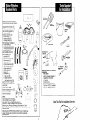
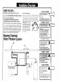
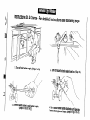
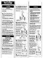
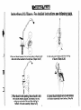
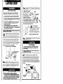
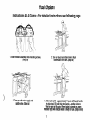
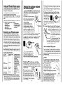
1
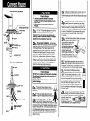
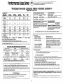
b&
ChIJ
Inst’dfat ion
Instructions
WHIRLPOOL
UNDERCOUNTER
REVERSEOSMOSIS
WATERFILTRATION
SYSTEMIV
I
n
Remove parts from packages.
Check that you have all the parts.
storage tank with base (A)
filtration assembly cover (B)
two mounting screws (C)
g-volt battery (D)
filtration assembly (E)
3/e”blue tubing (F)
l/4” yellow tubing (G)
l/4” orange tubing (H)
RO membrane cartridge (I)
3/B”black tubing (J)
%” red tubing wiih push-in
connector attached (K)
l/4” green tubing (L)
drain saddle elbow (M)
drain saddle valve
assembly (N)
air-gap faucet assembly:
faucet spout (0)
faucet base (P)
chrome base plate (Q)
LED indicator disk (R)
rubber washer (S)
slotted washer (T)
spacer (U)
flat washer (V)
l/4” hex nut (W)
3/s” grey connector
with push-in end (X)
packet of extra o-rings (Y)
saddle valve assembly (Z)
insert (AA)
plastic sleeve (BB)
brass compression nut (CC)
nitrate test kit (DD)
literature package
screwdriver
J
K
L
electric
drill or
drill bits
%s” wrench
or
Materials Needed for Basement
Installation
step ladder
shelf or bracket capable of
supporting 16 pounds
. l/4” drill bit
l
l
- safety glasses
- Basement Installation
Kit,
Part No. 4373517 available
from your Whirlpool dealer.
1 ~, _
NOTE:
Some state and local plumbing
J/ : 3
:odes prohibit the use of saddle1 in
type valves. The use of saddle-type valves is
prohibited In: Alaska, Delaware, Idaho, Kentucky,
Massachusetts, Michigan, Minnesota, New Hampshire, North
Dakota. Ohio. Oregon and South Dakota. Check your local plumb
zodes for details.
Open This Flap For Installation Overview
Massachusetts CMR 248 strictly prohibits the use of saddle-type
valves. The feed-water connection must conform to applicable
plumbing codes.
2
BeforeYouStart ...
IMPORTANT: Read and save these instructions.
It is recommended that this system be installed by a licensed
plumber. It is the responsibility
of the installer to comply
with the installation specifications
provided and with
state and local plumbing codes.
If you decided to install the system yourself, see
“General Information” on page 13 before continuing.
Water FlItration System IV can be installed In the basement if
there is not adequate room for under-sink installation, however. no more than 14 additional feet of tubing should be used.
Order Basement Installation Kit, Part No. 4373517 from your
Whirlpool dealer and follow the kit instructions. DO NOT use
filtration system if water is microbiologically unsafe or water
quality is unknown. Pretreat water that exceeds limits for
hardness, iron, manganese, and hydrogen sulfide.
HOOK UP WATER
If you need assistance
Refer to the Use & Care Information at the end of this
booklet. If you need more help. the WhIrlpool Consumer
Assistance Center WIII answer any questions you may
your RO water
have about operating or malntalnlng
filtration system. The WhIrlpool Consumer Assistance
Center is open 24 hours a dav. 7 days a week. Just dial
l-800-253-1301-the
call is ’
free. When you call, you will
need the RO water filtration
system model number and
senal number. Both numbers can be found labeled
on the top right side of filtratlon assembly.
piercing lance enters pipe and stops.
CONNECT
l
l
l
ReverseOsmosis
WaterFiltrationSystem
l
l
l
l
w
l
l
l
l
1
TUBING
Install RO cartridge into flItration
assembly. Connect one end of
red tubing to bottom of RO
cartridge. Connect other end to green
tubing from faucet.
Connect orange tubing to saddle valve.
Use orange tubing from filtration
assembly to fill storage tank with water.
Connect yellow tubing to storage tank.
CONNECT
l
FAUCET
Connect faucet spout, chrome
base plate, Indicator light disk
and rubber washer to faucef base. Q
Connect green tubing and black tubing
to faucet.
Place faucet in sink opening. Secure
faucet to sink with slotted washer,
spacer, flat washer, hex nut and grey
connector. Connect blue tubing to
bottom of faucet assembly.
Connect faucet indicator wire to wire
harness on filtration assembly
Insert balterv.
CONNECT
P-J
I
DRAIN
I
“../
’
I_^“’ *‘-”
whereTdq@‘sa‘sadd&Al
Decide whereTd@t
‘.: : g
;,. .,;*i’ $.!Jk
be mou
:,&
?‘;
;‘,
(I
on a ho
g& 0I. -1%::
.%..
above (
Connect drain saddle to drain pipe.
Drill hole In draln using openingjn drain
saddle as a guide.
? *,*
Thread elbow into drain saddle.
Connect black tubing to elbow.
FLUSH SYSTEM
. Slide flItratIon assembly onto
mounting screws
. Turn on faucet and drain tank to
flush dlslnfectant from tank
*Turn on cold water supply and
saddle valve.
l Allow tank to fill - approximately
4 hours
Lift faucet handle to drain tank. FIII and
drain tank agaln - another 4 hours. Walt
for tank to fill aoaln. When faucet is
turned on, gree% lndlcator light WIII
lndlcate water IS ready for use.
0
r
c
’
I
L,
Instructions At A Glance For detailed instructions see following page.
l
1. Turnoff cold watersupply.(Stepsla-lb)
2. Turnon faucetto drainwaterfrom line. (Step1b)
-
-
3. Connectsaddlevalveto cold watersupply.
(StepsWe or 1h-lj)
4. Turnsaddlevalvehandleclockwiseuntil piercing
lanceenterspopeandstops.(StepsIf-19 or 1k-l I)
Product Damage
DO NOT connect to a hot water supply line.
Failure to follow this instruction could result in
product damage.
Connect saddle valve to cold water supply
. soft copper pipe. Check that saddle valve
piercing lance does not protrude beyond rubber gasket. If it is protruding, carefully push it in flush with the
rubber gasket, using a hard object like the end of a
screwdriver handle.
Ic
Electrical Shock Hazard
Special care must be taken when drilling into
water pipes. Some water may remain in water
supply pipe.
If an electric drill is used, it must be properly
grounded to prevent severe or lethal shock if
water should enter drill.
l
Use only an electric drill that is double
insulated or properly grounded.
l
Check with qualified electrician if you are in
doubt as to whether your electric drill is
properly grounded.
l
Only drill at top or side of horizontal water
supply pipe. DO NOT drill at bottom of
horizontal plpe where water may remain.
Failure to follow these instructions could result in
personal injury or death.
l
Take note of water requirements listed
. under the Use & Care section of this booklet.
The filtration system’s feed line (orange tubing)
connects to your cold water supply line using the
saddle valve.
Do not use saddle valve if it is prohibited by your
state or local plumbing codes.
The saddle valve is for use with 3/e” to %” outer
diameter (O.D.), soft copper pipe (plain or chrome
plated) or rigid metal or plastic pipe. Important: DO
NOT use the saddle valve on flexible ribbed
tubing. The wall thickness of flexible ribbed tubing is
thin and will not support the saddle valve supplied.
If your cold water supply is connected to the cold
water faucet with flexible ribbed tubing, contact your
local plumbing supply distributor to obtain special
connecting hardware.
Important: If local codes do not permit the use
of saddle valves, special feed valves can be
obtained from your local plumbing supply distributor. Use only I%” polyethylene
tubing for water
line connection.
DO NOT USE COPPER TUBING.
la
Property/Product
Damage
DO NOT install tubing in an area where
temperatures
drop below 32°F.
DO NOT overtighten saddle valve to copper
pipe. This will crush pipe.
Keep a bucket or towel under area where
saddle valve connection is made.
Failure to follow these instructions
may result in
water damage to property or product damage.
l
l
piercing lance
should not protru
Assemble both halves of saddle valve to
cold water pipe. Saddle valve must be on top
side of horizontal pipe or side o
vertical pipe to keep sediment from collecting in its valve.
If you are connecting the saddle
valve to YB” O.D. copper pipe,
assemble bracket with
projections against tubin
to prevent distortion
of tubing. If you are
connecting the saddle
valve to 7/d’ or %” O.D.
-pipe. assemble bracket
with “v” side against
pipe.
Id
n
projections
’
a
“v’eide
Tighten screws evenly and firmly, keeping
. both halves parallel. DO NOT overtighten;
copper pipe could be crushed.
le
Turn off cold water SUDDIV. Turn on cold water
. faucet and allow all water to drain from line.
Turn off faucet. Determine if your cold water supply
line is soft copper pipe or rigid metal or plastic pipe.
If your cold water supply line is soft copper pipe
proceed to step 1c. If your cold water supply line is
rigid metal or plastic pipe, skip ahead to step 1h.
Connect saddle valve to cold water supply
. rigid metal or plastic pipe. Use a grounded
electric drill or hand drill to drill VW” hole in top side of
horizontal pipe or side of vertical pipe. This will keep
sediment from collecting in valve.
Turn saddle valve handle
n
II . clockwise to expose
piercing lance a maximum of 54.5”
beyond the rubber gasket.
n
Align piercing lance
9 . over hole you drilled in
pipe. Then assemble both
halves of saddle valve on
pipe with ‘v” side of bracket
against pipe. Tighten
screws evenly and firmlv.
keeping both-halves pa&llel. .,v,, sLe
Ik
Turn saddle valve handle
. clockwise until piercing lance
enters hole in pipe and then stops.
The saddle valve is now in the
closed position.
l
I
Ih
lb
II
Turn on cold water
supply to check for leaks. In case of leaks, use
an adjustable wrench to tighten nut below valve’s handle. Turn cold water back off and proceed to step 2.
E
n
Have a towel ready in case
. of leaks. Turn on cold water
supply to check for leaks. In case
of leaks, use an adjustable
wrench to tighten nut below
valve. Turn cold water back
off and proceed to step 2.
Instructions At A Glance For detailed nstructions see following page.
l
I. Connectfaucetspout,chromebaseplate,indicatorlight
disk and rubberwasherto faucetbase.(Steps2a-2b)
3. Placefaucetin sink opening.Securefaucetto sink
with slottedwasher,spacer,flat washer,hexnut
and greyconnector.Connectbluetubin to
bottom of faucetassembly.(Steps2e-si)
2. Connectgreentubing and blacktubing
to faucet.(Steps2c-2d)
4. Connectfaucetindicatorwire to wire harness
on filtration assembly.Insertbattery.(Step2k)
f-i
-.
Front view of air gap faucet
l
_ chrome
base elate
l
Property Damage
Contact a qualified installer or licensed
plumber for cutting a faucet opening in your
type of sink.
F!;IIwJ~
do so may result in damage to
2a
A 741”to 1%” diameter opening in the sink is
. required to install the faucet provided.
Important: If you do not have an existing sink
opening, contact a qualified installer or licensed
plumber to cut an opening in your sink.
indicator
light wire
-
Fhex
nut
Is-
%” grey connector
with push-in end
Side view of air gap faucet
k
spout
Property Damage
DO NOT cut or replace red tubing with white label.
The full length is needed for proper operation of
filtration system.
Failure to follow this instruction could result in
product damage.
air gap hole
slnk
%” tubing
black %” tubing
;lor;
downward
blue %”
tubing
Air gap faucet installation - remove base
. of faucet from parts bag. Remove and discard
small clear piece of tubing from opening on the top
of the faucet’s base. Push faucet spout into this
opening on the top of the faucet’s base. Assemble
hardware onto faucet base in this order: chrome
base plate, indicator light disk (lights should face
front of sink), rubber washer (slip cord of indicator
light disk through opening in rubber washer). Note:
Rubber washer may be removed and replaced with
a bead of plumber’s putty for neater appearance.
Determine which way handle should go.
2b
t
;fby;;
must
to
Feed green and black tubing, indicator wire and
threaded nipple through faucet hole in sink.
Position faucet spout over sink and indicator light toward
sink.
2f
Firmly push green tubing as far as
. it will go onto small opening of the air
gap faucet.
2c
2d
2e
Firmly push black tubing as far as it
. will go onto large opening of the faucet.
If your faucet hole is 1“-I%“, you
H can assemble spacer (open end up
toward air gap tubing), flat washer, hex nut and 3/e”grey
connector onto faucet’s threaded nipple before inserting
faucet in the faucet hole. Then secure faucet by inserting slotted washer between spacer and underside of
faucet hole with open side of slotted washer toward air
gap tubing. For smaller faucet hole openings follow
steps 2f and 29.
n
29
Working below sink, assemble slotted washer,
. spacer (open end up toward air gap tubing),
flat washer and hex nut onto faucet’s threaded nipple.
Make sure faucet is in proper position and tighten hex
nut with a %6” wrench or deep socket rachet until faucet
is secure. Thread the Y811
grey connector with push-in
end onto faucet’s threaded nipple. Tighten using
76” wrench.
2h
Recheck faucet position. Make sure indicator
. lights are facing the sink. I
faucet position needs minor
adjusting, wrap the flat
chrome sides of faucet
the crescent portion of
crescent wrench with
masking tape to protect th
chrome from scratches. Use
the wrench on flat sides of faucet to
reposition faucet. Remove masking tape.
21
.
Move filtration assembly near area where it
. will be mounted - either under sink or in the
basement. For best results, locate filtration assembly
so tubing can be cut to shortest length possible.
Blue tubing from filtration assembly
. attaches to bottom of faucet’s threaded
The blue tubino should be cut to the
shortest possible lengih. Use a plastic tubing
cutter or sharp razor knife to cut blue tubing to
shortest possible length. Make sure cut end is
clean and blunt and tubing is round. Firmly
push blue tubing from filtration assembly into
push-in connector on the bottom of the faucet’s
threaded nipple.
2k
5
Remove filtration assembly cover by liftirig it
. straight up. Connect the indicator disks wrre
to the electronic harness on the too of the filtration
assembly. Insert g-volt
battery in battery
receptacle on top of the
filtration assembly. Do not replace cover yet.
Instructions At A Glance For detailed instructions see following page.
l
1. InstallROcartridge
into filtration assembly.
Connectone end of red
tubingto bottomof RO
cartridge.Connectother
endto greentubingfrom
faucet.(Steps3a-3e)
Connectorangetubing
saddlevalve.(Step3f)
4. Connectyellowtubin
to storagetank.(Step3i3
3. Useorangetubingfrom
filtrationassemblyto fill
storagetank with water.
(Steps3g-3h)
The filtration assembly should already be
. placed close to its final location. Move storage
tank near its final location, which should be within four
feet of filtration assembly. The filtration assembly may
be installed under a sink or in the basement (mounted
to wood floor supports or to the basement wall). For
basement installation order Basement Installation Kit,
Part No. 4373517 available from your Whirlpool dealer.
Property/Product
Damage
DO NOT store or o erate the RO water filtration
system below 32 2 .
Remove red cap from
. top of RO cartridge. Allow
preservative from cartridge to drain into
sink. Rinse off the cartridge with tap
water and dry with a paper towel.
Wet O-ring seals with a little
water. Line up the tabs at the
top of the Rd cartridge with the
slots in the filtration assembly’s
t&is
receptacle. Push cartridge up and
turn it % turn to the right to lock it
in place. Cartridge label must face
front. Pull down on RO cartridge to
make sure it’s firmly in place.
Failure to follow above may result in water
damage to property or product damage.
Electrical Shock Hazard
Special care must be taken when drilling into
walls. Electrical wires may be concealed behind
the wall covering.
Use only an electric drill with a 3-wire power
supply cord connected to a grounded receptacle.
Check with qualified electrician if you are in
doubt as to whether your electric drill is
properly grounded.
Failure to follow these instructions could result ir
oersonal iniurv or death.
l
l
If cabinet walls are not solid, place filtration
. assembly on cabinet floor against cabinet wall. If
cabinet walls are solidly constructed, position filtration
assembly on right or left cabinet wall 2 inches (minimum)
above cabinet floor. Mark the location of mounting brackei
holes. Then set water filtration assembly aside. Drill pilot
holes for mounting bracket at locations marked on cabinet
wall. Insert mounting screws in holes and tighten, leaving
a slight gap between screw head and cabinet wall.
3b
grey push-i
Remove RO connector
. membrane cartridg
from plastic bag. Hold the
RO cartridge over the sink.
Push in the grey push-in
connector and hold; then
pull short white plug out of
connector and discard.
3c
&plug
To connect free end of orange tubing to saddle
. valve, place the brass compression nut on the
orange tubing (threaded side out), place the plastic
sleeve onto the tubing (discard brass sleeve), push the
insert into the tubing and thread this assembly onto the
opening of the saddle valve. Tighten brass
compression nut with Yz” wrench.
3f
3d
o-ring
seals
brass
cartridge
Product Damage
DO NOT cut or replace red tubing with white
label. The full length is needed for proper
operation of the filtration system.
Failure to follow this instruction
could result in
product damage.
eq
orange
\
Push the
grey push-in
v s free end
of red tubing into
the grey push-in connector
at the bottom of the RO
cartridge as far as it will go.
Red tubing from RO cartridg
attaches to green tubing from
faucet. Remove and discard short
piece of blue tubing from push-in
ther end of red tubing. The
should be cut to the shortest
le. Do not cut red tubing.
ing into grey push-in
he red tubing as far as it
tubing
3s
The storage tank may sit vertically or horizon. tally within four feet of filtration
assembly. If storage tank is to be mounted
horizontally on the cabinet floor, use tank
base as a cradle. To set tank vertically,
Push in grey push-in connector on top of
. storage tank to remove small piece of
tubing. Discard this tubing. The storage
tank contains a special disinfectant and
ust be filled with water now. To do
is, remove orange tubing from
filtration assembly and push it into
the storage tanks push-in connector
as far as it will go. Turn storage
tank’s blue valve on (up). Turn on cold water
supply. Turn saddle valve handle to the left to open.
Allow tank to fill (approximately 3 minutes). Turn off
cold water supply, saddle valve and tanks valve. Push
in tank’s push-in connector and remove orange tubing.
Allow water from orange tubing to drain into a bucket.
Reattach orange tubing to filtration assembly.
3h
To connect yellow tubing from filtration assembly
. to storage tank, cut yellow tubing to shortest
length possible - no longer than 4 feet. Make sure end
of tubing is clean and blunt and tubing is round. Push
yellow tubing from the filtration assembly as far as it will
go into storage tank’s push-in connector.
31
n
Instructions At A Glance For detailed instructions see following page.
l
1. Decidewheredrainsaddlewill be mounted. ,
Thebest placeis on a horizontaldrain tailpiece wI
above(before)the trap.(Steps4a-4b)
,
3. Drill hole in drain using o eningin
drainsaddleas a guide.(t tep 4d)
2. Connectdrain saddleto drain pipe.(Step4c)
4. Threadelbowinto drain saddle.Connectblack
tubingto elbow.(Steps4e-4f)
in
The drain saddle assembly is designed to fit a
. standard 1l/z” O.D. tailpiece. Smaller or larger
tailpiece piping will require
a special drain saddle
assembly available
@.
from your local
plumbing supply distributor. Position both
halves of the drain sad
on the tailpiece. Insert bolts
in drain saddle and tighten evenly and
firmly. Check that both halves of drain saddle
are parallel and equally spaced.
4c
Electrical Shock Hazard
Special care must be taken when drilling into
water pipes. Some water may remain in pipe.
- If an electric drill is used, it must be properly
grounded to prevent severe or lethal shock if
water should enter drill. Use only an electric
drill with a 3-wire power supply cord connected
to a grounded receptacle.
Check with a qualified electrician if you are in
doubt as to whether your electric drill is
properly grounded.
- Only drill at top or side of horizontal drain
pipe. DO NOT drill at bottom of horizontal pipe
where water may remain.
Failure to follow these instructions could result ir
personal iniurv or death.
l
You will need a
grounded electric drill
or hand drill and a l/4” drill bit
rill a hole in the drain pipe.
nsert drill bit into opening of drain
saddle. Operate drill slowly to drill
through one side of drain pipe.
4d
Make sure sink faucet is turned off and allow
. all water to drain from tailpiece. The drain
saddle valve must be installed above (before) the trap.
It should be mounted with the opening on the top of
horizontal drain pipe to avoid drain gurgling noise. If
this is not possible, it can be installed on a vertical
section of the drain pipe before the trap. For basement
installations, route drain line through an air gap to
laundry sink, floor drain or stand pipe.
4a
4e
n
Thread elbow into drain saddle. Tighten elbow
. as far as it will go.
Product Damage
The black tubing from the faucet must slope
downward without loops or low spots to the
drain saddle.
Failure to follow this instruction could result in
excessive drain noise.
L
Run black tubing to drain saddle. Check
. that tubing slopes continuously downward from
faucet without loops or low spots. Cut black tubing to
shortest length possible, make sure end of tubing is
clean and blunt and tubing is round. Push black tubing
into push-in connector on drain saddle elbow as far as
it will go.
4f
L-d
Inspect the condition of the sink drain pipe.
. Replace any trap or tailpiece that is in poor
condition. Water from the RO system drain line must
flow into a suitable drain. The black tubing from the
faucet must flow downward to the drain.
4b
Property/Product
Damage
DO NOT install drain saddle assembly to:
- a tailpiece used as a garbage disposal outlet.
- the bottom of a horizontal section of tailpiece.
Failure to follow these instructions
could result
in plugging of filtration system drain line.
tubi
gw P
come
FlushSystem
Instructions At A Glance For detailed instructions see following page.
l
I. Slidefiltration assemblyonto mountingscrews.
(Step5a)
3. Turnon cold watersupplyand
saddlevalve.(Step5c)
2. Turnon faucetand draintank to flush
disinfectantfrom tank.(Step5b)
4. Allowtank to fill - ap roximately4 hours.Lift faucethandle
to draintank.Fill anB draintank again- another4 hours.
Waitfor tank to fill again.Whenfaucetis turnedon, green
indicatorlight will indicatewateris readyfor use.(Steps5d-5e)
12
FlushSystem
Slide filtration asse
. mounting holes onto
mounting screws that were
installed in step 3b. DO
NOT kink or bend tubing.
Insulated staples may be
used to secure tubing to
cabinet walls. Tighten mounting screws to secure filtration
assembly to wall. Replace filtration assembly cover.
GeneralInformation
5a
In step 3h you filled the storage tank with
, water to activate the special disinfectant. If
that water has set in the tank for at least 15 minutes,
you can now drain the tank. To do this, turn the storage
tank’s blue valve on (up). Lift the faucet handle and
allow tank to completely drain. Close faucet.
Important: The storage tank must be filled and
drained two more times before the water is suitable
for use.
l
l
Turn on cold water supply and saddle valve.
. Check for leaks. (If the saddle valve leaks, refer
to “General Tips” on page 14 to make necessary corrections.) Lift faucet handle until a short but steady stream
of water flows - this can take about 15-20 minutes.
Water may intermittently spurt out from faucet opening
if air is trapped in the system. This is not a problem.
faucet handle and allow tank to fill.
Since the tank is now connected to the filtra5d . Close
tion system it will take about 4 hours to fill. DO NOT
use this water. Turn on faucet and drain tank. Close
faucet and refill tank, wait at least 4 hours and drain
system again. DO NOT use this water. It may contain
some disinfectant solution. Disregard indicator lights at
this time. When storage tank is emptied for the third
time, the sanitizing agent is completely flushed from
tank. The faucet will steadily drip when faucet is on.
Check that there is a steady drip from faucet.
system should be ready to use as soon
as the tank refills (about hours),
5e . The
4
and the
indicator disk’s light turns green when the faucet is
turned on. If any objectionable taste is present after the
third draining, or if the light is yellow, wait four more
hours and drain the tank again. As soon as the tank
refills, taste the water. If it has a taste you may want to
drain and fill the tank again. If water tastes okay, the
system is ready for use. When the faucet is turned on,
the indicator light should now be green.
5f. Conuratulations!
After installation, completely drain the system twice to remove sanitizing agent used during manufacturing. The green light on the indicator disk will light up when the sanitizing agent has been flushed out of
the system.
l
5b
5C
Water will not flow immediately from the faucet after installation. The Reverse Osmosis process is not
immediate and it may take up to four hours to fill the storage tank.
l
l
The flow rate from this system’s water faucet is dependent
tion and the water pressure in your home.
upon the amount of tubing used in installa-
DO NOT install this water filtration system outside of the home.
Maintenance of this
Replace the Sediment
the TFCM Membrane
water filtration system
water
(S),
(RO)
over
filtration system is very important.
GAC Carbon (GAC) and Carbon Block (CB) cartridges annually. Replace
Cartridge when the indicator disk light turns yellow. Failure to maintain this
an extended period of time could present health risks.
WaterRequirements
The filtration system must be connected to a cold
water supply line providing 40-l 00 psi water pressure.
If psi is less than 40, a booster pump, (Part Number
4373525) will be needed.
Review the water application guideline chart
below to determine if your water meets the standards
necessary to use this water filtration system.
DO NOT use filtration system if water is
microbiologically
unsafe or water quality
is unknown. Pretreat water that exceeds
limits for hardness, iron, manganese, and hydroI gen sulfide.
Failure to follow these instructions could result
in personal injury.
1
Application Guideline Chart
Water Supply Parameters
Water Supplycommunity or
private well
Potable
(suitable for
drinking)
Chemical
Limit
40-l 00 psi
40”.100°F
hardness
iron
manganese
4-11
hydrogen sulfide
< 350 mg/L
< 0.1 mg/L
< 0.05 mg/L
0
Water Pressure
Water Temperature
2000 ppm
turbidity
<I NTU
pH Range
pt;;nurn
TDS
GeneralTips
*For best performance of system, drain tank
completely once a week.
-To correct a leaky saddle valve, turn off cold water
supply and make sure saddle clamp screws are tightened evenly and firmly. DO NOT overtighten, you
could crush the pipe. Then make sure the nut below
the saddle valve’s handle is tight. If not, tighten it with
a ‘/” wrench.
l If the drain saddle
leaks, it may not be tightly
clamped. Tighten the bolts on both sides evenly
and firmly.
l If the drain saddle
elbow leaks, the connection may
be loose. Remove the elbow, wrap Teflon tape
around the threaded portion 2-4 times. Reinsert the
elbow into the drain saddle opening and tighten. DO
NOT overtighten.
*If the threaded portion of the brass compression nut tha
is attached to the saddle valve leaks, turn off saddle
valve and remove the nut, wrap Teflon tape around
the threaded portion 2-4 times. Reconnect the nut.
*If a leak should occur at a push-in connector, the cause
is usually defective tubing. To correct the problem turn
off water supply to the RO system either at the saddle
valve or other existing water valve. Push in the grey
push-in connector and hold; then pull the tubing out of
the connector. Cut at least Vi” from the end of the tubins
using a plastic tubing cutter or a sharp razor knife. Make
sure the cut end is clean and blunt and that tubing is
round. Reinsert tubing as far as it will go. Turn on water
supply at valve.
l If a cartidge
head leaks, it may have a misaligned,
pinched or damaged O-ring. Shut off the saddle valve
and tank valve. Open the faucet until dripping stops (5
minutes minimum). Turn filter cartridge % turn to the left
and remove. Replace the O-ring if it is misaligned,
pinched or damaged.
l If the spout leaks when faucet is closed,
it is either
because of an obstructed or defective valve seat in the
faucet or because the tee-bar under the handle is not
adjusted correctly. To check for obstruction, turn and lift
valve spout to remove. Slide faucet handle forward over
spout hole. Unscrew tee-bar and slotted bushing from
faucet valve. Remove faucet valve and check for
obstruction. Replace valve, Part No. 4373522, if necessary. To adjust the tee-bar, complete steps to check
ubstruction and then raise the tee-bar.
l If there is no steady
drip from the open faucet when
tank is drained, confirm that your cold water valve is
fully open. Confirm that the water saddle valve needle
pierced pipe and is fully open. Correct any leaks. Wait
for any trapped air to leave system. If the system was
connected to a refrigerator ice maker, the ice maker
valve may have been opened before installation was
completed. Turn the ice maker off and wait until faucet
drips.
*There are four things to check if the air gap opening
is leaking:
1. Blocked or improperly drilled drain line - clear drain
line, remove drain saddle and check for hole.
2. Air lock in gap outlet-blow
air into air gap using a
short tube.
3. Excessive drain flow - disconnect red tubing from
faucet air gap inlet tube. Check that drain flow is less
than 175 ml (% cup) per minute. If not, replace red
tubing with tubing of proper length available from
your Whirlpool dealer.
4. Black drain tubing plugged - remove blockage in
black drain tubing. Replace tubing if necessary.
14
*If you experience too little or no drain flow, the red tubing may be plugged or defective - replace red tubing
with tubing of proper length available from your
Whirlpool dealer. Confirm that the water saddle valve is
fully open. Check for obstructions in the faucet air gap
by removing the air gap and inspecting the flow path replace faucet if necessary. The Sediment or GAC cartridges may be clogged - replace if necessary.
l If you detect chlorine
or unpleasant tastes or odors
at startup, there may still be some sanitizing agent in
the tank. Drain and fill tank two to three times.
*If you hear gurgling or dribbling sounds in the drain,
check that 3/g”black drain tubing from faucet slopes
downward to drain saddle. Angle drain piping so drain
water runs down side of pipe. Or, change location
of drain saddle to horizontal drain pipe or alternate
vertical drain pipe farther from trap. Important: Make
sure drain saddle is installed before (above) trap.
If a garbage disposal is present, the water may be
dripping off the edge of the baffle. Rotate the vertical
drain pipe above the baffle so the filtration system drain
hole enters the pipe on the opposite side.
l If the water has a bad taste after filter cartridges
are
changed, the storage tank needs to be sanitized. Order
Tank Sanitizing Kit Part No. 4373527 and follow “How
to sanitize RO system” instructions.
Howyour ROwaterfiltration
systeinworks
Your RO water filtration system uses reverse osmosis
to help purify your water. When you use the system,
water is first filtered through a 5-micron filter to remove
particles 10 times smaller than your eye can see.
The water moves to the next cartridge and is forced
through granular activated carbon to remove chlorine and
taste-or-odor-causing compounds. The third
cartridge filters water through a reverse osmosis
membrane to reduce metals, salts and large organic
molecules when the faucet is turned on. Then the water
flows into the storage tank where it is ready to use. The
last (fourth) cartridge filters water from the tank again
through an activated carbon filter to remove any small
organic molecules and tastes that may still remain
in the water.
RO system production rate is 10.3 gallons per day at
50 PSI, 77°F and 715 mg/L NaCI.
Use this system only with water that has nitrate levels
limited to influent concentration of 30 mg/L or less. Use
the nitrate test kit provided with system to test nitrate
level of your water.
UsingyourROwaterfiltrationsystem
To get purified water from the storage tank - Hold
the faucet handle down for momentary flow, hold the
faucet up for continuous flow.
To stop water flow from the faucet - Return the
faucet to the center or horizontal position.
When faucet flow slows or drips - The storage tank
is empty. Wait 1 hour before dispensing any additional
water.
Ways purified water can be used - Your water filtration system has many uses, including:
Drinking water
Cooking water
Ice cubes
Mixing baby formula
Watering plants
Pet drinking water
Steam irons
Aquarium
Hand washing dishes
l
l
l
l
l
l
l
l
l
Maintainingyour ROwatersystem
How often RO Membrane, Sediment and Carbon
cartridges need to be replaced will depend on local
water conditions including dirt, iron and chlorine levels.
Private wells may require more frequent cartridge
replacement while softened water systems may only
require cartridge replacement once a year. The maximum length of time a filter cartridge should be used is
one year. Special water conditions where contaminants
are known should be regularly monitored by a public
health agency.
The RO membrane filter cartridge should be replaced
when indicator light changes from green to yellow. The
naximum length of time a RO membrane filter cartridge
should be used is three years.
Cartridge
Replace
Sediment
(1st on right)
Once/year
Carbon
(2nd from right)
Once/year
!
RO membrane
[3rd from right)
Carbon Block
:4lh from right)
Once/year
at least
Or replace
if or when...
-Water sup ly is cloudy
has high 2 rrt and rust
content change every
six mont I, s)
-Water amount or
flow from faucet is
noticeably reduced
-Water supply smells
of chlorine or water
has high dirt and rust
content fchanoe every
1 six months)
’
- Indicator light
changes from
green to yellow,,
even after drarnrng
tank twice
- Water has “off” taste
or odor
laintenance
of this water fillration system is very important.
Replace the Sediment 6). GAC Carbon (GAC) and Carbon Block
(C%) cartridges annuaky.‘tieplace
the TFCM iembrane
(RO) cartridge when the indicator disk light turns yellow. Failure to maintain this waler filtration system over an extended period of time
could present health risks
Replacingfilter cartridges-sediment
and Carboncartridges
1. Turn off water supply to RO system either at the
saddle valve or cold water valve. Open faucet to drain
tank. Wait five minutes for filtration assembly to
depressurize.
2. Lift cover off of filtration assembly. Rotate cartridge l/4 turn to the
left to remove connector tabs from
receptacle. Gently pull down to
eptacle
remove cartridge.
3. Check that label on new
cartridge matches label above
cartrldge
cartridge receptacle. Remove
red cap from cartridge. Wet O-ring
seals of new cartridge with a little
water. Line up the tabs at the top of
the new cartridge with the slots in
the filtration assembly’s receptacle. Push cartridge up
and turn it l/4 turn to the right to lock it into place.
Cartridge label must face front. Pull down on cartridge
to make sure it’s firmly in place. Repeat step if cartridge disconnects.
Y
4. Remove RO membrane cartridge from plastic bag.
Hold the RO cartridge over the sink. Push in the grey
push-in connector and hold; then pull short white plug
out of connector and discard.
5. Remove red cap from top of new RO cartridge.
Allow preservative from cartridge to drain into sink.
Rinse off the car0
tridge with tap water
o-ring
seals
and dry with a paper
towel. Wet O-ring
f
tabs
seals with a little
water. Reinsert red tubing into
push-in connector of new
‘B RO
cartridge.
6.
Line up the tabs at the top of the RO cartridge with
the slots in the filtration assembly’s receptacle. Push cartridge up and turn it l/4 turn
to the right to lock it into place. Cartridge
label must face front. Pull down
on cartridge to make sure it’s
firmly in place. Repeat step if filter disconnects.
7. Turn on water supply. Open
faucet and allow water to run
for 2 minutes to check system for leaks. If
water leaks, shut off water and recheck
connections. Replace cover.
Howto sanitizeROsystem
4. Turn on water supply. Open
faucet and allow water to run for
carlridge
2 minutes to check system for
leaks. If water is leaking, shut off
I
I
water and recheck connections. Replace cover.
ReplacingROmembranecartridge
1.
When indicator light changes from green to yellow,
turn off water supply, open faucet to drain tank and turn
off saddle valve. Wait five minutes for filtration assembly
to depressurize.
2. Lift cover off of filtra- connector
tion assembly. Push in the grey
push-in connector near bottom of
RO cartridge and remove tubin
3. Rotate bad RO cartridge l/4
to the left to remove connector
from receptacle. Gently pull dow
remove cartridge.
15
You will need new Sediment and Granular Activated
Carbon cartridges, household bleach and eyedropper.
1. Turn off saddle valve in water line. Open faucet and
drain tank. There will be no water dripping when tank is
completely empty.
2. Remove Sediment and Granular Activated Carbon
cartridges.
3. Remove caps from new cartridges. Insert new
Sediment cartridge into receptacle with symbol that
matches the one on label.
4. Use eyedropper to
inject 1 teaspoon (5ml)
of bleach into hole in top
of new Granular Activated
Carbon cartridge. Insert
cartridge into receptacle
matches the one on label.
5. Turn on saddle valve in water line. Wait
6 hours before using system. Open
faucet and drain tank. There will be
water dripping when tank is empty.
Allow tank to refill. If water has a taste,
drain tank and allow it to refill again.
Call l-800-253-1301 to order.
Replacement Parts & Accessories
r
Replacement Cartridge Kit
Howto sanitizethe storagetank
You will need to order Tank Sanitizing Kit, Part No.
4373527. You will also need household bleach and
a measuring spoon.
1. Turn off saddle valve in water line. Open faucet
and drain storage tank. There will be no water dripping
when tank is empty.
2. Turn off faucet. Push in grey connector to disconnect
yellow tubing from system. Connect yellow tubing to push
in connector on side of sanitizing kit.
UsingROsystemafterlong periods
of non-use
1.
I
Follow instructions for replacing cartridges.
TFCM Membrane Cartridge (RO)
Sediment Cartridge (S)
GAC Carbon Cartridge (GAC)
Carbon Block Cartridge (CB)
SFC Flow Control (Red Tubing)
Filtration Assembly Cover
Storage Tank
Air Gap Faucet
Refrigerator Hook-up Kit
Additional Parts
Needed For Multiple
“T” Connector with
Connections:
% Rejection Monitor
2. Sanitize storage tank.
3.
Sanitize RO System.
4. Follow “Flush System” instructions.
If YouNeedAssistance...
The WhirlpoolConsumerAssistanceCenter will answerany questionsabout
operatingor maintainingyour RO water filtrationsystem not coveredin
the InstallationInstructions/Useand Care Guide.The WhirlpoolConsumer
AssistanceCenter is open 24 hoursa day, 7 days a week. Just dial
l-800-253-1301-the call ib free.
Whenyou call, you will need the RO water filtrationsystem model number
and serial number.Both numberscan be foundlabeled on the top right side
of the filtrationassembly.
3. Disconnect orange tubing from filtration assembly.
Connect orange tubing to tank sanitizing kit’s other
push-in connector.
4. Put M ieaspoon of bleach into tank sanitizing kit.
5. Turn on saddle valve in water line. Allow storage
tank to fill for about 3 minutes. Turn off saddle valve in
water line and the valve at the top of storage tank.
6. Wait 15 minutes. Disconnect tank sanitizing kit
from storage tank. Disconnect the orange tubing from
the tank sanitizing kit.
7. Reconnect orange tubing to filtration assembly.
Reconnect yellow tubing to filtration system.
8. Turn on saddle valve in water line and the valve
at top of storage tank. Open faucet and drain tank.
There will be water dripping when the tank is empty.
9. Allow tank to refill. Wait about 6 hours. Drain tank
again and allow it to refill. If water has a taste, drain
lank and allow it to refill again.
HowTo ArrangeFor Service...
In the event that your Whirlpoolappliance shouldever need service, call the
dealer from whom you purchasedthe appliance or a Whirlpool-authorized
service company.A Whirlpool-authorizedservice companyis listed in the
YellowPages of your telephonedirectory under “Appliances-Major-Service
or Repair.”Youcan also obtain the service company’sname and telephone
numberby dialing, free within the continentalUnitedStates, the Whirlpool
ConsumerAssistanceCenter telephone number,l-800-253-1301.A special
operatorwill tell you the name and numberof your nearestWhirlpoolauthorizedservice company.
Maintainthe quality built into your Whirlpoolappliance-call a Whirlpoolauthorizedservice company.
MODEL
MODEL
4373575
4373501
4373502
4373503
4373504
4373500
4373509
4373511
4373522
4373505
%” Tubing
4319151
Push-in Ends
4319152
4373512
4373513
LED Faucet Base Assembly
Installation Instructions
lme+~llotion
Kit
JLcaIICIL.-..
-.Tubing Kit
4373514
43735008
4373518
4373519
%” Green Tubing 4
Spare “0” Ring Kit
4373516
4374515
4373520
Drain Saddle Assembly
Saddle Valve, Self-tapping
Basement Installation Kit
Booster Pump
Tank Sanitizing Kit
W Connector
with Push-in
4373521
4373517
4373525
4373527
4373546
4373547
4373548
Ends
% “T” Connector with Push-in Ends
%-l/d Male Connector with Push-in Ends
%-l/4 Reducing Connector
with Push-in
l/4 Elbow Connector
with Push-in Ends
IV REVERSE
OSMOSIS
NO. WSR413YW
REPLACEMENT
I
Flow Sensor
W Elbow
CARTRIDGE:
Connector
DRINKING
WHIRLPOOL
WHIRLPOOL
with Push-in
WATER
4373556
4373557
Ends
TREATMENT
RO FSP# 4373501
GAC FSP# 4373503
4373549
Ends
UNIT
WHIRLPOOLS
FSP# 4373502
WHIRLPOOL CB FSP# 437504
SERVICE FLOW RATE - 0.6 gpm (2.26 Ipm)
MAX. OPERATING PRESSURE -100 psig (862 kPa)
MIN. OPERATING PRESSURE - 40 psig (345 kPa)
MAX. OPERATING TEMPERATURE
100°F (36°C)
Preparationfor long periodsof non-use
Follow these instructions if RO system will not be used
for more than 30 days.
1. Turn off saddle valve in water line. Open faucet to
drain tank. There will be no water dripping when
tank is completely empty. Wait five minutes for filtration
assembly to depressurize.
2. Remove all cartridges. Place cartridges upsidedown in sink or bucket to drain water from cartridges.
Place cartridges in a plastic bag and seal tightly. Place
bag with cartridges in refrigerator. DO NOT allow
cartridges to freeze.
Kit includes Sedimenl (S), GAC Carbon (GAC) and
r-*c-~
Block (CBI Carlridaes. Cartridaes can also
be ordered ind’iiid;ally. TFEM Membr&e Cartridge
(RO) needs replacing only once every lwo years,
when indicator disk light turns yellow.
NOTICE: DO NOT USE WHERE WATER IS MICROBIOLOGICALLY
UNSAFE OR WITH WATER OF UNKNOWN
QUALITY.
THIS PRODUCT HAS BEEN TESTED AND LISTED UNDER NSF STANDARD 56 FOR TOTAL DISSOLVED SOLIDS, ARSENIC,
BARIUM, CADMIUM, CHROMIUM, NITRATE. LEAD, MERCURY, RADIUM, AND SELENIUM REDUCTION. SEE PERFORMANCE
DATA SHEET FOR PERMISSIBLE CLAIMS.
NITRATE REDUCTION MODELS (“NITRATE”) ARE ACCEPTABLE FOR TREATMENT OF INFLUENT
TO 30 mg/L; ADDITIONAL TREATMENT SHALL BE REQUIRED FOR HIGHER INFLUENT LEVELS.
THIS SYSTEM IS NOT CERTIFIED
OF LESS THAN 40 PSI.
WHIRLPOOL
16
CORPORATION,
FOR NITRATE REDUCTION
BENTON HARBOR,
IN WATER SUPPLIES
CONCENTRATIONS
WITH A PRESSURE
AND FILTER REPLACEMENT
AS ADVERTISED-*
0
NSF@
MI, USA.
IT IS ESSENTIAL THAT OPERATIONAL, MAINTENANCE
BE CARRIED OUT FOR THE PRODUCT TO PERFORM
UP
REQUIREMENTS
PerformanceDataSheet @
Q
This Reverse Osmosis System has been tested and listed by NSF International
under Standard 58 for the water treatment claims listed below under
“Contaminant Reduction Performance”.
Whirlpool Reverse Osmosis Water Filtration System IV
Model No. WSR413YW
Purification
Assembly Components
Sediment Prefilter: 5 micron Nominal Depth
Cartridge
Carbon Prefilter:
Activated Carbon
Membrane Type:
Thin Film Composite (TFCM)
Carbon Postfilter:
Activated Carbon
General Performance
Testing Laboratory’
System Production: 10.3 gal/day (39 liters/day)
Minimum TDS Reduction: 96%
‘Raed
at 50 psi, 77°F. 750 mg/L N&I,
product
to storage
tank.
Factory Specifications**
Standard Tank Capacity: 2.6 Gallons maximum.
Membrane Production:
14-20 gal/day HighFactory sanitized and ready to install.
Flow Membrane
Reject Water: This drinking water appliance has a
Membrane TDS Reduction: 96% Minimum
self cleaning feature that requires approximately
“Rated at 60 psi, 77°F. 350+ mglL TDS, product lo atmosphere.
3 gallons of rinse water for every gallon of high
Note: Actual produtiion
rate and TDS reduction will depend
quality water used.
upon temperature.
water pressure.
variation and usage pattern.
All Drinking Water Appliances
Test Parameters
TDS = 200500 mg/L2
In addilion to the contamlnanls
listed above. these systems
llke Chlorides, Phosphate, Sodium and Sulfates
APPLICATION
Membrane
TvDe
Temperature
Water Pressure
Water Temperature
TFCM
Chlorinated
Onlv
= 77°F
Pressure = 50 psig
Maximum TDS Level
AND FEATURES
I
1
4-11
I
2000 ppm
I
Iron
Hvdroaen
1 co.1 mg/L
Sulfide
Turbidity
I
co.05 mg/L
I
0
I
cl NTU
I
CAUTION:
Da Not usa where water is microbiologically
unsaie or with water of unknown quality
Waler supplies that exceed limits lor Hardness, Iron, Manganese.
Hydrogen Sulfide require pretreatment.
Important Quality Assurance Requirements
This Reverse Osmosis Drinking Water system contains treatment components that are
critical for effective reduction of Total Dissolved Solids as well as inorganic contaminants.
A water quality monitor (indicator light disk) is build into the system to provide the user with a
means to test the water at any time. Refer to “Use and Care Information” for operation of the
water quality monitor (indicator light disk).
I
for additional
One Year Full Warranty
(from date of purchase)
Replacement parts and repair labor to correct defects
in materials or workmanship for the entire product
except for the filter cartridge(s). Servicing must be
provided by an authorized Whirlpool servicing outlet.
Five Year Limited Warranty
(second through fifth year
from date of purchase)
Replacement parts to correct defects in materials or
workmanship for the entire product except for the
filter cartridge(s).
Whirlpool shall not be liable for Incidental or consequential
damages. Some states do not allow
the exclusion or limitation of incidental or consequential damages, so this limitation or exclusion may
not apply to you.
This warranty gives you specific legal rights, and you may also have other rights which vary from
state to state.
Change as required based on the built-in water quality monitor.
*Refer to “Use and Care Inlormation”
will pay for:
The performance and functioning of your water filtration system is directly related to the quality of
the water being treated and the particular application in which it is used. Please consult “Water
Requirements” and “Use & Care”.
Routine Maintenance
Sediment Prefilter, Carbon Prefilter and Carbon Postfilter: Change once per year’
Membrane:
Whirlpool
Whirlpool will not pay for:
A. Service calls to:
1.) Correct the installation of the product. System must be installed and operated in accordance with Whirlpool procedures and guidelines.
2.) Instruct you how to use the product.
3.) Correct house plumbing.
El. Repairs when product is used in other than normal, single-family household use.
C. Repairs when product is damaged from neglect, misuse, abuse, freezing or hot water, fouling
with sediment or scale, bacterial attack, alterations, improper installation, or installation not in
accordance with local plumbing codes.
D. Any labor costs during the limited warranty.
E. Replacement parts or repair labor costs for units operated outside the U.S.
F. Pickup and delivery. This product is designed to be repaired in the home.
G. Repairs to parts or systems caused by unauthorized modifications made lo the product.
Limit
~350 ma/L
Manganese
Length of Warranty:
chemicals
Chemical
Hardness
1
I
non health-related
Water SUDDIV Parameters
1 40”-100°F
(4.4 - 36°C)
reduce
I
1 40-l 00 psi (3-7 Kg/cm2)
DH Ranoe
I
also have Ihe ability to effectively
GUIDELINES/SPECIFICATIONS
1
Water Supply-Community
or Pnvate Well
I
are factory tested, sanitized and prepared for installation.
WARRANTY
Turbidity = 1 NTU
pH = 7.5
‘USEPA Maximum Contaminanl
Level or Action Level (mg/L).
3arrium.
Cadmium and Chromium were tested at 750 mglL TDS.
3The reduction of Radium was verified by using Barium as a surrogate under NSF prolocol.
‘These conlaminanls
are not necessarily in your water supply. Periormance
may vary based on local water conditions
I
TDS level, membrane
conditions.
17
Part No. 4373500 Rev B
01993 Whirlpool Corporation
Whirlpool Corporation
Benton Harbor, MI 49022
Printed on Recycled Paper in U.S.A.
@