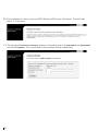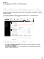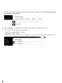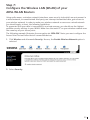
1
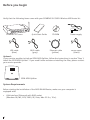
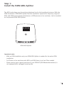
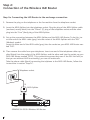
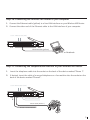
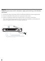
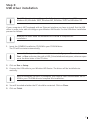
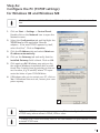
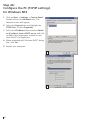
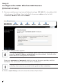
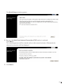
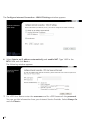
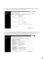
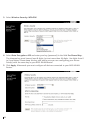
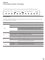
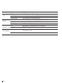
Quick Start Guide
SIEMENS SLI-5300-I
Wireless IAD Router
•
Do never open the housing!
•
Use only the power supply provided with this device.
•
Use only the cables provided with this device and do not
perform any modifications on them.
06-20080428
Before you begin
Verify that the following items came with your SIEMENS SLI-5300-I Wireless IAD Router kit:
SIEMENS SLI-5300-I
Quick Start Guide
ADSL cable
(gray)
USB cable
(blue)
CD-ROM
Power supply
Ethernet cable
(yellow)
Phone cable
(black)
Optional:
If your service provider include an ISDN ADSL-Splitter, follow the instructions in section “Step 1:
Install the ISDN ADSL-Splitter”. If you need further assistance installing the filter, please contact
your service provider.
ISDN ADSL-Splitter
System Requirements
Before starting the installation of the ADSL WLAN Router, make sure your computer is
equipped with:
•
2
LAN interface (Ethernet) with RJ45 socket
(Windows 98, ME, NT4, 2000, XP, Vista, Mac OS 9.x, 10.x).
Step 1:
Install the ISDN ADSL Splitter
The ADSL technology uses the existing telephone line for the broadband entrance. With the
ISDN installation a ISDN ADSL-Splitter must be installed to separate the frequency ranges of
ADSL and ISDN and to prevent disturbances at ISDN phones or fax machines. Use for installation the provided ISDN ADSL-Splitter.
ISDN ADSL-Splitter
Important note:
-
With an ISDN installation only one ISDN ADSL-Splitter is needed for the entire ISDN
installation.
-
For Phones or fax machines with ADSL and ISDN there is no Line-Filter needed.
-
Please contact your support-technician if your ISDN-NT (ISDN Networkterminator) is
not equipped with a plugged incoming line.
3
Step 2:
Connection of the Wireless IAD Router
Step 2a: Connecting the IAD Router to the exchange connection
1. Remove the plug on the telephone or the fax machine from the telephone socket.
2. Insert the ADSL-Splitter into the telephone socket. Plug the plug of the ADSL-Splitter cable
(enclosed, mostly black) into the “Phone” (F) plug of the telephone socket and the other
plug into the “Line” (Amt) plug of the ADSL-Splitter.
3. Set up the connection between the ADSL-Splitter and the ADSL IAD Router. To do this, insert the end of the ADSL cable (gray) into the socket of the ADSL-Splitter with the "DSL"
(Modem) symbol.
Insert the other end of the ADSL cable (gray) into the socket on your ADSL IAD Router marked "DSL".
4. Then remove the cable from your telephone. Insert one end of the telephone cable supplied (black) into the socket of the ADSL-Splitter, and the other end into the socket on your
ADSL IAD Router marked "PSTN". This connection ensures that even if the DSL link fails (so
that you are without VoIP functionality) you can still make calls.
Take the phone cable (black) connecting the telphone to the ADSL IAD Router, follow the
instructions in section “Step 2c”.
Telephone socket
2.
2.
ADSL-Splitter
3.
4.
2
1
Phone
1
PSTN
DSL
2
Ethernet
3
4
USB
Power
SIEMENS SLI-5300-I Wireless IAD Router
4
Step 2b: Connecting the Wireless IAD Router to your computer
1. Connect the Ethernet cable (yellow) to a free LAN interface on your Wireless IAD Router.
2. Connect the other end of the Ethernet cable to the LAN interface of your computer.
to the ADSL-Splitter (DSL)
2
1
Phone
1
PSTN
DSL
2
3
4
Ethernet
USB
Power
Ethernet cable (yellow)
2.
PC or Notebook
Step 2c: Connecting the telephone/fax machine to your Wireless IAD Router
1.
Insert the telephone cable into the socket on the back of the device marked "Phone 1".
2.
If desired, insert the cable of a second telephone or a fax machine into the socket on the
back of the device marked "Phone2".
to the ADSL-Splitter (DSL)
2
1
Phone
2.
1
PSTN
1.
DSL
2
3
Ethernet
4
USB
Power
Ethernet cable (yellow)
Phone cable (Phone 1)
Phone 2 or Fax machine
5
Step 2d:
Connecting the mains unit for the power supply and switching on the Wireless
IAD Router
1. Connect the plug on the power cable to the Wireless IAD Router's power supply socket.
2. Insert the other end of the cable into a convenient mains socket.
3. Switch on the Wireless IAD Router using the switch on the back of the device.
After a brief powering-up period, the device's operational readiness is indicated by the
power LED (green) and the DSL LED (green) lighting up.
to the ADSL-Splitter (DSL)
2
1
Phone
1
PSTN
DSL
2
3
Ethernet
4
USB
3.
Power
1.
2.
Ethernet cable (yellow)
Phone 2 or Fax machine
6
Step 3:
USB driver installation
The USB driver is only working on the following operating system (OS):
Windows 98, Windows 98SE, Windows ME, Windows 2000 and Windows XP.
If your computer is NOT equipped with an Ehternet interface you have to install first the USB
driver in order to be able to configure your Wireless IAD Router. For the USB driver installation
proceed as follows:
Windows 98 users need the Windows 98 CD-ROM to complete the
installation.
1. Insert the SIEMENS installation CD-ROM in your CD-ROM drive.
The CD will be startet automatically.
In case the “setup wizard” does not start automatically, open a Run window via
Start --> Run and enter the path x:\USB_Driver\windows\setup.exe, where x represents the drive letter of the CD drive.
2. Click on Run or Setup.
3. Connect the USB cable to your Wireless IAD Router. The driver will be installed automatically.
Note for Windows 98 users: If prompted, you need to insert the Windows 98 CDROM in your CD-ROM drive to complete the installation.
4. You will be asked whether the PC should be restarted. Click on Close.
5. Click on Finish.
7
Step 4:
Configure the PC (TCP/IP settings)
Introduction
In step 4, you will learn how to configure your computer to communicate with the Wireless IAD
Router.
To do this, you will need to configure your PC’s network settings to obtain an IP address automatically. Computers use IP addresses to communicate with each other across a network or
the Internet.
Find out which operating system your computer is running, such as Windows 98, Windows Me,
Windows NT4, Windows 2000, Windows XP, Windows Vista or Macintosh OS 9.x, 10.x.
You will need to know which operating system your computer is running. You can find out by
clicking on Start -> Settings. (If your Start menu doesn’t have a Settings option, you are running Windows XP or Windows Vista. You can select the Control Panel directly from the Start
menu.) Then, click on Control Panel and double-click on the System icon.
Click the Cancel button when done.
Once you know which operating system you are running, follow the directions in this step for
your computer’s operating system.
8
Step 4a:
Configure the PC (TCP/IP settings)
for Windows 98 and Windows ME
Windows 98 users need the Windows 98 Installation CD to complete the installation.
1. Click on Start -> Settings -> Control Panel.
Double-click on the Network icon to open the
Network screen.
2. Select the Configuration tab and highlight the
TCP/IP line for the applicable Ethernet
adapter1). If the word TCP/IP appears by itself,
select that line2). Click on Properties.
3. Click the IP Address tab and select Obtain an
IP address automatically.
4. Click on the Gateway tab and verify that the
Installed Gateway field is blank. Click on OK.
5. Click again on OK. Windows may ask you for
the original Windows Installation disk or additional files. Supply them by pointing to the correct location, e.g. D:\win98, where “D” represents the letter of your CD-ROM drive.
2
6. If Windows asks you to restart your PC, click on
Yes. If Windows does not ask, restart your computer anyway.
3
1)
Choose a TCP/IP entry whose name contains Ethernet adapter. Do not choose
a TCP/IP entry whose name is PPPoE, VPN or other.
2)
If there is no TCP/IP line listed, refer to the User Manual on your Aethra CD-ROM
to install TCP/IP now.
9
Step 4b:
Configure the PC (TCP/IP settings)
for Windows NT4
1. Click on Start -> Settings -> Control Panel.
Double-click on the Network icon. The
Network screen will appear.
2. Select the Protocol tab and highlight the
TCP/IP line. Click on Properties.
3. Select the IP Address tab and select Obtain
an IP address from a DHCP server and click
on OK on the subsequent screens to complete the PC’s configuration.
4. When prompted with “Activate DHCP” dialog
box, click Yes.
5. Restart your computer.
2
3
10
Step 4c:
Configure the PC (TCP/IP settings)
for Windows 2000
1. Click on Start -> Settings -> Control Panel.
Double-click on the Network and Dial-up
Connections icon. The Network screen will
appear.
2. Select the Local Area Connection icon for
the applicable Ethernet adapter (usually it is
the first Local Area Connection listed).
Double-click on Local Area Connection and
click on Properties.
3. Select Internet Protocol (TCP/IP) and click
on Properties.
2
4. Select Obtain an IP address automatically
and click on OK on the subsequent screens
to complete the PC’s configuration.
5. Restart your computer.
3
4
11
Step 4d:
Configure the PC (TCP/IP settings)
for Windows XP
The following instructions assume you are running Windows XP’s default interface. If you are
using the Classical interface (where the icons and menus look like previous Windows versions), please follow the instructions for Windows 2000 (Step 4c).
1. Click on start -> Control Panel. Click on the
Network and Internet Connections icon.
Click on the Network Connections icon. The
Network screen will appear.
2. Select the Local Area Connection icon for
the applicable Ethernet adapter (usually it is
the first Local Area Connection listed).
Double-click on Local Area Connection and
click on Properties.
3. Select Internet Protocol (TCP/IP) and click
on Properties.
2
4. Select Obtain an IP address automatically
and click on OK on the subsequent screens
to complete the PC’s configuration.
5. Restart your computer.
3
4
12
Step 4e:
Configure the PC (TCP/IP settings)
for Windows Vista
1. Click on start -> Control Panel. Click on
the Network and Sharing Center icon.
Click on Broadband Connections →
Properties.
2. The “Local Area Connection Status”
screen will appear. Click on the
Properties button.
3. Select Internet Protocol Version 4
(TCP/IPv4) and click on Properties.
4. Select Obtain an IP address automatically and click on OK to complete the
PC’s configuration.
2
5. Click on the OK to finish the configuration.
3
4
13
Step 4f:
Configure the PC (TCP/IP settings)
for Mac OS 9.x
1. From the Apple Menu, point to
Control Panels and then click TCP/IP.
2. From the Connect via pull-down
menu select Ethernet built-in. From
the Configure pull-down menuselect
Using DHCP Server.
3. Close the TPC/IP window and click on
[Save].
2
14
Step 4g:
Configure the PC (TCP/IP settings)
for Mac OS X
1. From the Apple Menu, select System
Preferences...
2. Click on the Network icon in the Internet
& Network area.
3. From the Show pull-down select Built-in
Ethernet. On the TCP/IP tab, select Using
DHCP from the Configure pull-down
menu.
4. On the PPPoE tab, make sure that the
Connect using PPPoE check box is NOT
activated. Click Apply Now.
2
5. Close the Network window.
3
4
15
Step 5:
Configure the ADSL Wireless IAD Routers
(Internet Access)
1. Start your web browser (e.g. Internet Explorer) and type 192.168.1.1 in the address field
of the browser. Press Enter. Enter in the field <Username> admin and in the field
<Password> admin as well and click Next>.
2. The Quick Setup window appears:
If the Quick Setup page is not displayed, please check the TCP/IP settings of your
computer (obtain IP address automatically must be enabled). Find more information about the configuration in chapter 4.
Enter your username and password, which you can get from your provider, and click
Connect>. The connection to the Internet will be established.
If the connection to the Internet won’t be established, please proceed with step 3
and follow the instructions provided in this guide for basic installation.
3. Click on Quick Setup on the left side of the window “Quick Start”.
16
The Quick Setup window appears:
4. Be sure, the Auto Scan Internet Connection (PVC) option is selected.
Click Next >.
The scanning process will be started and can take several minutes. Afterwards the
detected connection will be displayed.
5. Click Next >.
17
The Configure Internet Connection - WAN IP Settings window appears:
6. Select Optain an IP address automatically and enable NAT. Type 1492 in the
MTU: field and click Next >.
The following window appears:
7. For <PPP User Name> enter the username and for <PPP Password> the password.
You can get this information from your Internet Service Provider. Select Always On
and click Next >.
18
8. Take over the settings displayed in the Configure LAN side Settings window and
click Next >. The LAN configuration will be started.
9. The window This Internet Connection - Summary shows the WAN and LAN settings
you made. The values must match to those values you get from your ISP. Click
Finish to accept these settings and to terminate the configuration.
19
10. The installation is done and your ADSL Wireless IAD Router will reboot. This will take
about 1- 2 minutes.
11. The window Connect to Internet appears. If needed, enter the username and password
and click Connect>. The connection to the Internet will be established.
20
Step 6:
Configuration of the VoIP interface
VoIP (Voice over IP) is a voice service offered by the internet service provider. Here, the voicesignal is transmitted via the internet. VoIP not only offers a realtime voice service, but also
connects you to any location across the whole world. VoIP offers you new ways of using your
broadband connection. You simply need to connect your telephone via an adapter in order to
receive the service.
You need to perform the following configuration steps in order to make use of VoIP:
1. Select the Voice and then the SIP Basic.
1
1
2
2. Choose a pre-entered SIP provider, or select Others.
Your SIP Provider will give you the necessary details for the configuration:
- SIP Registrar Address: Must always be entered,
- SIP Proxy for outgoing connection: If you receive no details from your SIP provider,
this field can remain empty,
- SIP Proxy Server Address: If this is not specified by the SIP provider, enter the same
address as for the SIP Registrar.
21
3. Using the details supplied by your Internet provider, complete the fields Phone Number,
User Name and Password.
3
4
4. Click on Apply, to complete the configuration and set up the connection.
5. The successful call setup is indicated by
- Status: Your voice service is ready.
- Telephone 1 VOIP mode
- Telephone 2 VOIP mode (only if telephone 2 is present and configured under point 3).
5
22
Step 7:
Configure the Wireless LAN (WLAN) of your
ADSL WLAN Routers
Using radio waves, a wireless network introduces some security risks which are not present in
a wired network; an unauthorized third party can intercept transmitted data, gain access to
your wireless network. In order to make your wireless network as secure as a wired network
you should apply, at least, the following guidelines.
To guarantee that your data is transmitted in a private manner, you should use the highest
possible security settings in your WLAN. Make sure that each PC on your wireless network uses
the same key as your access point.
The following example illustrates the encryption via ‘WPA-PSK’. Note: you must configure the
Access Point first and after that all connected devices.
1. Click Wireless and afterwards Security. Be sure, the Enable Wireless Network option is
selected.
2. Select Security.
23
3. Select Wireless Security: WPA-PSK.
4. Select Data Encryption: AES and enter your key (password) in the field Pre-Shared Key:.
The choosen key must have at least 8 digits, but not more than 64 digits. Use digits from 0
to 9 and letters. Please keep this key safe and be sure you are configuring your Access
Point(s) with the same key as your ADSL WLAN Router.
5. Click Apply. Afterwards you must configure all devices connected to your ADSL WLAN
Router.
24
Step 8:
Front panel system messages
The following illustration shows the front panel of the ADSL IAD Wireless Routers:
Power DSL
PPP
Ethernet
1
2
3
VOIP
Ready
USB WLAN Phone
4
1
2
LED Indicators
The ADSL IAD Wireless Routers is equipped with LEDs on the front panel as described in the
table below (from left to right):
Function
Color
Definition
Off
Power is off
Solid Green
Power is on and the device operates normally
Solid Red
Power on self-test in progress
Power
The device enters the console mode of the boot loader
Power on self-test failure if the led always stays solid red
DSL
PPP
Ethernet
Flash Red
Firmware upgrades in progress
Off
No DSL signal is detected
Slow Flash Green DSL line handshaking in progress
Fast Flash Green
DSL line training in progress
Solid Green
DSL line connection is up
Off
No PPPoA or PPPoE connection
Solid Green
At least one PPPoA or PPPoE connection is up
The users can access the Internet now
Off
No Ethernet signal is detected
Flash Green
User data going through Ethernet port
Solid Green
Ethernet interface is ready to work
25
Function
USB
WLAN
Color
Definition
Off
No USB signal is detected
Flash Green
User data going through USB port
Solid Green
USB interface is ready to work
Off
The device is powered off or WLAN is disabled
Flash Green
User data going through WLAN port
Solid Green
WLAN interface is ready to work
Off
Phone 1 or 2 Solid Green
VOIP phone call is in use
Off
Voice over IP service is not ready. The users only can make
PSTN phone calls
Solid Green
Voice over IP service is ready
VOIP Ready
26
The phone is on-hook or in PSTN mode
Declaration of Conformity
Siemens Switzerland Ltd confirms that this device meets the essential requirements and other
relevant regulations laid down in directives 2004/108/EC and 2006/95/EC.
A copy of the 2004/108/EC and 2006/95/EC Declaration of Conformity is available at this
internet address: http://www.siemens.ch/broadband
27
28