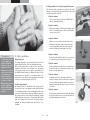
1
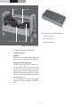
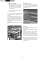
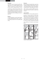
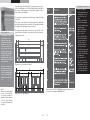
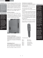
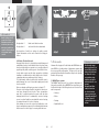
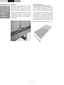
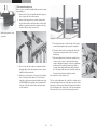
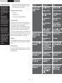
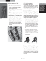
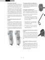
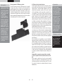
Bock Manual –
centroflex
Tubular Steel Products
Interior Furnishings
Therapy and Rehabilitation Beds
Assembly and
Operating Instructions
Content
Dear Customer,
In deciding to buy a therapy and rehabilitation bed from Bock
you have opted for a care product that has a long service life
and delivers first class functionality at the highest safety level.
Our electrically adjustable care beds guarantee optimum
comfort when lying, and support professional care activities.
The focus is on people who need care, encouragement and
protection. We have created the basic requirements for this
with our care products. We urge you to prevent potential
malfunction and risk of accidents by complying strictly with
the safety and operating instructions and carrying out the
necessary maintenance.
4
1. General information
1.1 Practical – no packaging
1.2 First impression – visual inspection
6
2. Cleaning, care and disinfection
2.1 Cleaning and care
2.2 Disinfection
2.3 Avoiding danger
8
3. General description of function
3.1. Structure and function
3.2 How to assemble fast and easily:
3.3 Caution: Risk of injury
17
4. Electric components
4.1 Drive unit
4.2 Control box for all functions
4.3 Control box for individual functions
4.4 Height adjustment drive unit
4.5 Lockable hand control, single fault safety
4.6 Caution: Electrical drive unit
21
5. Drive units
5.1 OKIMAT drive systems
5.2 Mains isolation
24
6. Accessories
6.1 Special sizes
6.2. Assembling bed extensions
6.3 Assembling accessories
6.4 Mattresses
6.5 Special mattress ripocare
30
7. Setting up and operating – centroflex
7.1 Design and purpose
7.2 Special features
7.3 centroflex in parts
7.4 The centroflex ready for use
7.5 Control
7.6 Disassembly
7.7 Relocation
7.8 Transport and storage conditions
7.9 Functioning advice
7.10 Disposal
7.11 Troubleshooting
38
8. Safety guidelines
8.1 Safety guidelines for electrically operated bed systems
8.2 The “Top-Ten” safety guarantees.
8.3 Technical safety checks with service
Yours sincerely
Klaus Bock
3
> Tip from Bock
1. General information
Please refer to the
assembly instructions
for your specific model
(from chapter 7 on) to
see which parts, and
how many of them, have
to be present for your
visual checks of the care
bed.
The various bed systems that are made by Hermann Bock
GmbH meet the special requirements for use in rehabilitation and therapy establishments as well as for care at home.
Their reliable functioning and long service life mean that all
our beds are of a particularly high quality. Our beds need
little maintenance when used and inspected properly. No
bed leaves the Hermann Bock production plant until it has
passed final quality inspections and has been tested by a
technical inspectorate in Germany named TÜV. Every health
bed thus meets the requirements of directive 93/42/EEC for
medical products. The beds are tested not only on the basis
of the new European standard EN 1970 but also on the basis
of EN 60601-2-38 – the standard for electric medical equipment with special specifications for the safety of electrically
operated hospital beds.
The electric components of our beds conform with safety
standard EN 60601-1 for medical devices.
All care beds are subjected to a careful function check on site
by our trained delivery staff. At the same time authorised
persons are given basic training in the functioning and safe
handling of the beds. Additional information is given in the
Bock security guide, these assembly and operating instructions and in the “Upgrading with Bock” brochure.
* Warning note from Bock
As the user, you should
read these installation
and operating instructions completely in order
to avoid any damage
or malfunction in the
course of assembly and
use.
Note: An evaluation of the bed in accordance with EN
60601-1 is only partly possible, since for beds there is the
product specific standards EN 60601-2-38+A1. Should there
be product specific standards, these should be used in the
first place for testing. EN 60601-1 is used additionally for
electronic testing.
1.1 Practical – no packaging
Bock has developed a special system that enables our care
beds to be transported reliably and stored in a space-saving
way. The intelligent Bock plug-in system is very environmentally-friendly because it comes with minimal any packaging
material. Furthermore, the bed can be assembled easily and
quickly by one person. Bed models that require more extensive assembly work are put together completely on Bock’s
premises and shipped without packaging.
1.2 First impression – visual inspection
Before assembling the bed and putting it into service, look
at it carefully to see that it is complete and has no visible
damage. Only when you are convinced that the bed is in
its proper, fault-free state should you get round to learning
the correct way of using the individual bed elements in the
following function description.
E.g. in this way you have
your centroflex care bed
including its transport and
storage system
Explanation of symbols used on name plate:
Mark of conformity according to guidelines
for medical products
Protection of electrical parts from splashwater
„Medical equipment part, type B“
„Only to be used in dry environment“
Protection class II (duoble Iinsulation, protective insulation)
This product must be disposed to a selected waste disposal
within the european union. This product may not be disposed
together with unsorted domestic waste.
Take note of the accompanying documents
4
5
> Tip from Bock
2. Cleaning, care and disinfection
Scratches that go
through the entire coating should be sealed
with suitable repair
agents to prevent the
penetration of moisture.
The individual bed elements are made of first-class materials, largely from steel, whose surface has been given a
durable polyester powder coating.
The surfaces of all wooden parts have been sealed with a
material that contains no harmful substances. The patented
ripolux support system is made of high-grade plastic. All bed
elements can be easily cleaned and looked after with wipeand-spray disinfectants that meet the hygiene requirements
for the various areas of use. The usefulness and optical condition of your care bed will be retained for a long time if you
heed the following care instructions.
2.1 Cleaning and care
Steel tubing and sprayed metal parts:
To clean and care for these surfaces use a moist cloth with a
mild commercial household cleanser.
Wooden, decorative and plastic parts:
All common furniture care and cleansing agents are suitable.
To clean plastic parts a moist cloth with a mild commercial
household cleaner is suitable. A special product for plastic
material should be used for the care of plastic surfaces.
Hygiene certificate:
ripolux fulfils all requirements that are set out for a product
after suitable cleaning with listed products in accordance
with the currently valid German Society for Hygiene and
Microbiology (DGHM) list and according to the Robert-KochInstitute (RKI-guidelines) “Hygiene Requirements for the
Treatment of Medical Products”, the recommendations for
infection protection, and was therefore certified.
2.2 Disinfection
All disinfectants set out in EN 12720 can be wiped on the
beds to clean them. To maintain the material condition of
plastic elements such as the motor housing, decorative elements, ripolux and ripoplan, only use mild agents. Concentrated acids, aromatic and chlorinated hydrocarbons, high
alcohol, ether, ester and ketone corrode the material and
should therefore not be used.
2.3 Avoiding danger
Before cleaning and disinfecting electric parts of your care
beds it is essential to read the following rules in order to
avoid danger in conjunction with cleaning and disinfecting
them. Failure to comply with these rules can result in personal injury and considerable damage to the electric cabling
and the drive unit.
Motor unit:
The motor housing should only be wiped with a slightly
moist cloth in order to prevent moisture getting into it.
1. Pull the mains plug out and place it where it cannot
come into contact with excess water or cleaning
agents.
The ripolux and ripoplan support system:
To clean the plastic carrier and spring elements as well as
the base use a slightly moistened cloth without adding any
cleaner, or add a product that has been designed specifically
for plastics. If the support system needs particularly intensive cleaning, remove the spring elements from the carrier
elements by turning them 90° to the left and pulling the
carrier elements from the lying surface frame, which takes a
few minutes. The plastic elements that you have removed in
this way can be cleaned or sprayed with hot flowing water.
The plastic elements can be sprayed with a suitable plastic
cleaning agent for disinfection. Most of the moisture can be
removed from the surface of the plastic by a gentle shaking,
the remainder will dry within a short time. After drying thoroughly with no residue, re-assemble the parts.
Alternatively the individual lying surface elements can be
completely removed from the frame and cleaned (see chapter 3.1 and 3.2).
2. Check that all plug-in connections fit properly.
6
3. Check the cabling and electric parts for damage. If
you detect any damage do not clean the parts involved but first make sure that the defect is eliminated
by the operator or by authorised technicians.
4. Before putting the bed back into service check that
the mains plug does not have any residual moisture
on it, and rub or blow it dry if necessary.
5. If you suspect that moisture may have penetrated
any electric components pull out the mains plug
immediately, or do not reconnect it to the mains if
you have already removed it. Take the bed out of
service without delay, label it accordingly, and notify
the operator.
7
* Warning note from Bock
Never use scouring
agents or other abrasive cleansers, cleaning
pads or stainless-steel
care agents to clean
the beds. Nor should
you use organic solutions such as halogenated/aromatic hydrocarbons and ketones,
or acidic and alkaline
cleaners.
The bed must never be
sprayed with a water
hose or high-pressure
cleaner because this
could let moisture penetrate the electric components, thus leading
to malfunctions and
danger.
Back support
Upper leg support
The ripolux support system includes the following:
4
plastic carrier elements
51 plastic spring elements
Fixed seat section
Lower leg support
51 rubber connecting pieces
centroflex bed with ripolux support system
3. General description of function
3.1. Structure and function
Lying surface
All Bock care beds can be equipped with two different lying
surface versions as an option to the a stable slatted frame:
The patented ripolux anti-decubitus system
The patented ripolux support system is available for any
lying surface. ripolux consists of a comprehensive tubular
steel lying surface frame with four lying sections: Back
support, fixed seat section, upper leg support and lower leg
support. On the lying surface frames there are four ripolux
carrier elements made of high-grade plastic with a total of 51
spiroplex spring elements.
The electrical adjustment of ripolux is performed without
limitation in the same manner regardless of the Bock bed
model.
8
9
3.2 How to assemble fast and easily:
1. Place the carrier elements with the pre-assembled
Spiroplex spring elements on the cross-rails of the
lying surface frame in such a way that the Velcro patches lie exactly on top of each other, and press the
elements firmly together.
The ripoplan plastic base system
The four plastic base elements can be easily fitted onto the
same carrier system as ripolux. The ripoplan lying surface
is just as functional as a slatted frame and offers additional
advantages when cleaning.
2. If necessary press the spring elements firmly into the
rubber connection points.
Do the following if you need to remount individual spring
elements after disassembly, for example after cleaning or
replacement:
Place the Spiroplex spring elements individually on the carrier elements one after another. For that simply place every
spring element (A) with its rubber connection piece (B) into
the designated fixing hole and fix it there with a light push.
Make shure that all elements are aligned in exactly the same
way and straight.
To disassemble the spring elements jerk them off of the lying
surface.
The ripoplan support system
Functional areas
The functional areas of all four versions are identical and are
spread over four areas:
Back support, fixed seat section, upper leg support and lower
leg support.
The frame for the lying surface is made of welded steel
tubing that has been covered with a PE powder coating.
The height of the lying surface is continuously adjustable by
means of 24 V direct current motors that are operated via
the easy-to-use hand control. The back support is electrically
adjustable from 0 to 70 degrees. The electrical adjustment of
the ripolux lying surface and ripoplan plastic base system is
performed without limitations in the same manner regardless of the bed model.
10
11
The leg section
The leg section consists of a two-part foot unit. Each individual position can be continuously adjusted by pressing
a button on the hand control. The electronic hand control
can also be used for an automatic tri-function to raise the
occupant‘s legs to a stretched position and to make a bend
in the area between the heart and knees. The lower leg
support automatically moves parallel to the lying surface
in proportion to the upper leg support. The leg section can
be lowered with the aid of a 9-volt battery in the event of a
power failure.
The chassis
The telescopic lifting chassis consists of a basic frame whose height is adjusted by two lifting columns. The surface of
this steel tubing construction has a heat seated PE powder
coating.
The siderails
Every care bed has two integrated siderails on each side at
a height that is designed to guarantee safety. The siderails
can be raised and lowered by a steel bar. The parts that move
are particularly quiet as an impact damper has been built in,
and the ends have an ornamental cap. With an ergonomically formed release button the siderails can easily be raised
or lowered.
Usage of the siderails
If the side lattices are to be lowered, hold them by the designated groove of the upper siderail (fig. 1), lift this siderail
firmly and press the release buttom either on the head or
on the foot section (fig. 2). The siderail is now released on
that side and can be lowered downwards up to the impact.
Now the siderail is in an diagonal position. In order to lower
the other side, you’ll have to perform the steps described
above on that side, too. The side rail is now in the lowered
position.
left: Fig. 1, center: fig. 2, right: fig.3
12
13
If you want the siderails back in the upper position as a protection from falling out of the bed, get the upper siderail in
the center of the grasp-groove and pull it upwards, until it
locks at both ends audibly.
* Warning note from Bock
– Only use original
Bock siderails that are
available as accessories for all our care
beds.
– Only use technically
perfect, undamaged
side rails with the permissible gaps.
– Make sure that the
side rails slot into
place securely.
– Before attaching the
side rails and before
every movement of
the bed, check all
mechanical parts of
the bedstead and
siderails that are used
to fasten the siderails
to make sure they are
not damaged.
– The operation of
the side rail should
always be carried out
with utmost care, since fingers can easily
be squashed between
the longitudinal bars.
The siderails are primarily intended to stop occupants falling
out of bed.
They may not be sufficient for fragile patients so additional
protective measures have to be taken, for example by adding
relocatable siderail bumpers (an accessory).
> Tip from Bock
There must be a minimum height of 22 cm
without compression
when different mattress
thicknesses are in use.
This is measured from
the top edge of the side
rail above the mattress.
When higher mattresses
are used, a side rail
attachment that is available as an accessory has
to be installed.
The bars that make up the side rail must be at most 12 cm
apart. When the siderails are used they must not remain in
a diagonal position.
Dimensions of a continuous siderail
Various care beds from
Bock have special functions that you can find
in the assembly instructions for the individual
models from chapter 7
on.
Note:
When the struts/fixing
points of the siderails
are outside (shown in
light blue), then distance
A to the lying surface
is required beneath the
siderails.
Extract from the TÜV PS 51036 test program, dimensions of
the siderail according to EN 60601-2-38
Dimensions of a split siderail
14
15
> Tip from Bock
In the event of uncertain
malfunction, failure or
damage of the electric
bed or its accessories,
the first thing you
should do is to remove
the mains plug and activate the emergency lowering appliance. Please
inform the operator or
the Bock service team
about the problem.
* Warning note from Bock
The operator has a duty
to decide to undertake
special safety measures
for very agitated individuals in care, in order to
prevent trapping of any
limb or a person completely falling out.
The Bock service team
is happy to advise you
on special solutions for
these care situations.
3.3 Caution: Risk of injury
Proper use of all movable parts is essential to guarantee the
safety of occupants, carers and nursing staff. The correct
assembly and operation of the bed are essential for this. The
physical constitution of the specific individual and the type
and extent of disability must be taken into account when
using the bed.
Use a control box to avoid hazards resulting from unintentional motor adjustments and incorrect handling. When the
user, for example a nurse or caring relative, leaves the room,
the functions of the hand control should be disabled completely by using the hand control key or disabled by using
the separate control box. Then the lying surface has to be
brought to its lowest position and activated the disabler with
an appropriate turn of the key in the keylock located on the
back.. Withdraw the key and as a precaution check that the
hand control functions are actually disabled. Turn the knob
switch when using a control box. These recommendations
apply especially
> When the occupant is unable to use the hand control
properly because of certain disabilities
Motor housing
4. Electric components
> When the occupant could be put in danger as a
result of unwanted adjustments
> When the siderails are in a raised position and there
is risk of trapping or injuring the occupant
> When children are in the room containing the bed
without supervision
When the hand control is not in use, make sure it is hung on
the hook on the bed and cannot fall off.
The bed should only ever be operated by nursing staff or
relatives who have received training, or in the presence of
such persons.
When adjusting the lying surface, make sure that no limbs
protrude into the siderails in the area that is being adjusted.
When the siderails themselves are adjusted, it is essential to
make sure that the occupant is in the right position, too.
Before starting an electrical adjustment always check
whether any limbs are present in the adjustment area
between lower chassis and back or lower leg section or even
any child or person between the floor and raised lying surface. There is a particular high risk of injuring here.
4.1 Drive unit
The drive unit consists of the motor box in which there are
two motors for the individual drives to adjust the electrically
operated parts of the back and leg supports. The integrated
motor box incorporates a transformer and a rectifier in which
the input voltage of 230 V at 50 - 60 Hz at 150 W is converted
to low voltage of 24 V DC. The motors and the hand control
operate with this non-dangerous low voltage. The cables
are doubly insulated, and the mains plug has a primary fuse
in accordance with EN 60601-1. An additional mains isolation appliance is coupled to actuation of the hand control.
Emergency lowering of the bed is driven via a 9 V monobloc
battery. Furthermore, voltage selection ensures the constant speed of functions. Safety features thus conform with
protection class II and, for protection against moisture, IPX4
according to EN 60529.
* Warning note from Bock
The maximum period
of operation of 2
minutes must not be
exceeded. Afterwards
it is essential to leave
it unused for at least 18
minutes.
9-volt battery for emergency
lowering
16
17
> Tip from Bock
When isolated from the
mains, the bed is completely free of electromagnetic radiation. Electricity is only consumed
when adjustments are
carried out.
* Warning note from Bock
Although all Bock care
beds are made to a very
high safety standard
this does not mean that
there are no risks.
Only when the manufacturer’s specifications
are heeded and the beds
are used properly do the
safety measures fulfil
their actual purpose
– acting on a preventive
basis and actively avoiding risk.
If the maximum adjustment time of two minutes is exceeded,
for instance through fiddling with the hand control, and if
the motors overheat, the thermal release will immediately
disconnect the power supply from the bed. Power will automatically be restored after a cooling-down time of about one
hour. Since this drive does not operate at a frequency rate >
9 kHz and is mainly run for short periods, the guideline EN
550014-1 applies according to EN 60601-1-2 36.201.1.4.
4.2 Control box for all functions
The series hand control with six keys is fitted with an integrated disabling function which enables carers to lock the hand
control completely. The easy disabling function in the hand
control can therefore replace the current control box, when it
is necessary to cut off the entire function of the bed.
4.5 Lockable hand control, single fault safety
Basic functions can be controlled by the press of a button on
the ergonomic hand control using the six extra-large, userfriendly operating buttons.
The individual buttons are labelled to indicate their function.
The motors run while a button is held down.
A coiled cable allows the necessary freedom of movement
for operating.
The hook on the back can be turned 90° in both directions.
The radius corresponds exactly to the radius of the side rail
and support so that the handset fits securely. Special attention should be paid that during cleaning, disturbance by the
hand control position be averted by turning it or clipping it
to one of the appropriate places on the bed. The hand control also has an integrated disabler that can be activated or
deactivated by its key.
To disable the entire electrical function, insert the key into
the lock located on the rear and activate or deactivate the
disabling function with a corresponding twist of the key.
Control box
4.3 Control box for individual functions
In conformance to the user regulation or following the hospital standard EN 60601-2-38 the drive is also available with a
disabler, with which the back section and lower leg section in
the down position can be separately cut off (Trendelenburg
position).
4.4 Height adjustment drive unit
The level of the lifting chassis can be adjusted via one or two
built-in low voltage DC motors whose adjustment range is
defined by an integrated limit switch. The height adjustment
drive unit is connected by a coiled cable to the control unit.
18
The new Bock hand control
Button 1
Button 2
Button 3
Button 4
Button 5
Button 6
19
Back section up
Back section down
Lower leg section up
Lower leg section down
Lying surface up
Lying surface down
* Warning note from Bock
Simultaneous use of
electrical equipment
can, particularly in the
immediate environment of the bed when
it is ready to operate,
result in small electromagnetic interactions
between the electrical
devices, similar to the
interfering noise heard
on the radio. In such a
rare cases, increase the
distance between the
devices, do not use the
same wall socket, or
temporarily switch off
either the interfering
device or the one being
interfered with.
If the bed, contrary
to its intended use, is
operated in combination with electrical and
medical devices, the
function of the bed
must first be deactivated by means of the
integrated locking function in the hand switch
for the duration of use.
> Tip from Bock
Switch settings I and II
operate the testing of
individual switches and
should only be used by
authorised qualified personnel in the framework
of the annual safety
controls.
Key for disabler
Knob position 1
Knob position 2
Hand control functions active
and control functions deactivated
Knob positions 3 and 4 are settings for safety controls.
Further information on this can be found in the safety guidelines.
4.6 Caution: Electrical drive unit
Hermann Bock refers to its electrically operated therapy and
rehabilitation beds as health beds because they have many
functions that help their occupants to recover physically and
psychiologically while reducing pain. As medical devices,
electric beds require special safety precautions including
handling in a suitable way for safety, daily checks of electric
equipment and proper maintenance and cleaning.
To avoid damage, cables should be laid outside the area in
which damage can occur. Contact with edged parts should
also be avoided.
Hints on adequate cable laying are given in chapter 7.7.
Excessive touch voltage should be avoided in order to prevent injury through electric shocks. These circumstances
may arise, in particular, when the mains cable has been
damaged, when there is inadmissible, excessive leakage
current, or when liquid has penetrated the motor housing,
for example because of incorrect cleaning.
Such damage can cause the controls to malfunction, resulting in unwanted movements of the individual bed elements
that increase the risk of injury for nursing staff and users.
20
5. Drive units
Hermann Bock equips all health beds with OKIN drive systems. OKIN is a leading maker of adjustment systems with
the necessary skills and expertise. This gives rise to an ideal
partnership for medical devices with a unique level of quality
thanks to this synergy.
5.1 OKIMAT drive systems
The OKIMAT dual drive unit for continuous adjustment of
lying surfaces and the linear OKIDRIVE as a single drive unit
to adjust the height of the lifting chassis each consist of four
main components.
21
–
Housing
–
Motor
–
Gearing
–
Spindle with nut
* Warning note from Bock
No drive unit components are allowed to be
opened! Only specially
authorised technicians
are allowed to carry
out troubleshooting
activities and replace
individual electric components.
Assembly and disassembly instructions
for electrical technicians are given in the
“Upgrading with Bock”
brochure, in part II
– Instructions for electricians.
> Tip from Bock
The 9-volt batteries in
the control should be
tested once a year to
see that they are functioning correctly, and be
replaced if necessary. In
addition visual inspections should be regularly
carried out.
9-volt battery for emergency
lowering
The principle of the housing for the OKIMAT dual drive unit
and linear OKIDRIVE guarantee that all components will continue to function for a long time. The special design principle
is based on two force-absorbing capsules. The patented,
detailed interior design of the housing ensures that the
drive technology will sit accurately. Ready-made, complete
assemblies are not used. OKIMAT housings are characterised by particularly easy assembly/disassembly and convenient space for the battery and electronic parts beneath
the robust cover. The OKIMAT can also be combined with
all OKIN controls as an additional drive unit. The OKIMAT
has an isolation appliance in the mains plug and features
emergency lowering. The noise level of OKIN drive units can
exceed 65 dB(A).
5.2 Mains isolation
The OKIN mains isolation facility that is integrated in the
mains plug provides other practical advantages in addition
to guaranteeing a high level of safety. Activation of mains
isolation prevents magnetic and electric alternating fields
from being generated in the bed. The mains isolation facility
operates independently and does not require an additional
transformer for its standby mode. When the drive unit has
been disconnected from the mains, no electricity is used and
a switching noise in the relay indicates correct operation.
Of course, mains isolation is compatible with higher-level
mains isolation options.
22
The OKIN isolation facility in the mains plug is activated by
pressing a button on the hand control. A capacitor charged
with direct current in the drive unit supplies electricity to
the two-pole relay in the mains isolation facility, and turns
on the transformer in the drive. The capacitor is recharged,
and is ready for the next actuation. Whenever the button on
the hand control is released, the relay in the mains isolation
facility turns off the mains network (two poles). A switching
noise indicates that this function is being executed. The 9volt battery that is installed in the control as standard for
emergency movements will, if necessary, back up the mains
isolation capacitor if the latter has not been used for some
time and has therefore lost its voltage. If the capacitor and
the 9-volt battery have been exhausted, it is sufficient to
press the green button to get the mains isolation facility
working again.
When taking the bed out of service, the contact to the 9 Volt
battery should be released by pulling out the plug.
mains isolation closed and open
23
* Warning note from Bock
For reasons of safety,
only use original accessories from Bock that
have been released for
the bed model in question. A precise overview
of accessories and extras
for your bed is given in
a separate data sheet.
Hermann Bock GmbH
will assume no liability
for any accidents, damage, injury and risks that
come about through the
use of other accessories.
6. Accessories
6.2. Assembling bed extensions
A bed extension includes the following parts:
Hermann Bock GmbH offers practical accessories that promote mobility to ensure that every care bed can be tailored
to the specific requirements of its occupants. The accessories are attached easily and securely to the fixing points on the
bed. Of course, every element of these accessories complies
with Bock’s special quality and safety standards. Beds can be
extended to a length of 220 cm so that tall persons, too, can
lie comfortably in them and enjoy the same level of functionality. Alongside our standard accessories for every bed we
have an extensive range of extra accessories. These extras
vary depending on the bed model, and are adjusted to the
bed’s special functions and place of use. These extra accessories range from technical elements through mattresses
to a companion bed. A wide choice of wooden designs and
colour variants is available so every care bed can be integrated harmoniously in existing surroundings.
2 adapters for the left and right foot sections
–
1 wire brace for the foot section
–
1 set of siderails
–
Screws
Easy assembly with a clip system is as follows:
1. Remove the mattress from the lying surface.
2. Remove the end piece from the foot section.
3. Attach the adapters to the foot end of the lying surface and screw them on.
4. Place the wire brace on the foot unit, drill holes (diameter = 4.2 mm), and screw the parts together.
6.1 Special sizes
At Hermann Bock GmbH, special sizes are standard models
in our production processes.
Occupants with a particular physical build can only lie with
optimum comfort if the beds have been specially made for
them. With our special sizes, Hermann Bock enables every
care bed to be tailored specifically to the occupant’s physical
condition. For persons taller than 190 cm Bock recommends
using a bed extension that lengthens the lying surface up to
220 cm. In this way tall persons can lie in comfort and have
the same level of functionality. Other special sizes and special functions are available in Bock’s range of special beds as
described in the “Bock Works In Special Ways” brochure.
24
–
5. Slide the end piece of the foot section directly in
front of the release button.
6. TAKE NOTE of the markings above and below the
end caps of the siderails as it is essential that theymust not be confused.
7. Insert the siderails in the pre-assembled metal
guides and centre it.
8. Push the release button inwards and slide in the foot
section until it clicks into its borehole provided
25
> Tip from Bock
Of course, the Bock
service team will also
assemble bed extensions if required.
Bock always recommends that mattresses
and bedding should be
made of fire-retardant
material in accordance
with DIN EN 597.
* Warning note from Bock
When using accessories
on the bed or medical
devices such as infusion stands in the direct
vicinity of the bed, make
sure that adjustment of
the back and leg supports does not subject
nursing staff to the risk
of squashing/shearing.
6.3 Assembling accessories
The following standard accessories can be combined with
every Bock bed model:
Urine bottle/bag holder, 1.2 kg (Fig. 5)
Package: 1 C-profile,1 urine bottle/bag holder, screws
–
Hold the C-profile in the middle beneath the longitudinal tube of the lying surface, mark the position of
a hole, drill holes with a dia meter of 4.2 mm, and
fasten with the screws that are in the package.
–
Make sure that one end of the C-profile rail is directly touching the foot section cross-connection.
Attachable siderails, 3.8 kg (Fig. 1)
Package: 2 siderails screws
–
Loosen the screws on the side rail, insert the side
rail, position it in the middle and tighten the screws.
Lifting pole with grab handle, 6.5 kg (Fig. 2)
The safe load limit of the lifting pole is 75 kg max.
Package: 1 lifting pole with mounting ring, 1 grab handle
Goose-neck all-purpose clamp, 0.6 kg (Fig. 6)
Package: 1 clamp, 1 goose-neck, 1 fastening ring
–
Insert the lifting pole in the headboard receptacle
and arrest it, attach the grab handle to the mounting
ring.
–
The height setting of the triangle should be at a distance of no less than 550 mm to >= 700 mm from
the upper edge of the respective mattress (mattress
height of 100 mm and 120 mm) to the lower edge of
the horizontal grip.
Fig. 1
The all-purpose clamp is a special holder that enhances its
manoeuvrability as a basic component and enables the flexible positioning of the modular functional accessory. It is possible to fasten bags, urine bottle holders, infusion systems
or a lamp, individually or at the same time. The goose-neck
all-purpose clamp can also be attached onto the side rail
exactly as required.
–
The goose-neck is clamped onto the upper side rail
and attached to the fastening ring.
Side rail bumpers, 1.4 kg (Fig. 3)
Package: 1 cover, 1 item of bumpers
Fig. 2
–
Open the zipper of the cover, pull the bumpers on to
the side rail from above.
–
Pull the foam bumpers from the inside of the bed
into the cover, and close the zipper.
Tray, 4.0 kg (Fig. 4)
Package: 1 bed tray
–
Place the bed tray on the side rail. The tray is prevented from slipping by two spacers.
Left: Fig. 5, right: Fig. 6
Fig. 3
Fig. 4
26
27
> Tip from Bock
The Bock service hotline will be pleased
to advise you about
the optimum upgrade
option for your bed.
Please phone
+49 (0)180.5262500
An extensive range of
additional furniture is
available to supplement the various Bock
bed models. The products available extend to
the entire furnishing of
rooms, thus combining
care and convenience
of living in a special
way.
> Tip from Bock
The bock service hotline
will be pleased to advise
you about the optimum
mattress for our ripolux
support system.
Please phone
+49 (0)180.5262500
6.4 Mattresses
Basically all foam and latex mattresses that have, at least, a
volume weight of 35 kg per cubic meter and do not exceed
a height of 10 to 12 cm for the dimensions of 90 x 190 cm,
100 x 190 cm, 90 x 200 cm and 100 x 200 cm can be used for
Bock health beds. When higher mattresses are used, a side
rail attachment that is available as an accessory has to be
installed. When foam mattresses are used, we recommend
making nicks in them so that they can be adjusted better to
the lying surface.
28
6.5 Special mattress ripocare
ripolux system-mattress for nearly pressure-free lying
The system-principles of Bock combines the intelligent lyingsurface ripolux with the specially developed care-mattress
ripocare to a lying-system, which perfectly absorbs any pressure. The combination of PU- and cold foam in a sandwich
configuration enables a high point elasticity and body-adaptiveness. With that, the 10 cm high ripocare system-mattress
ideally amplifies the functions of ripolux. Special cut-outs
ensure, next to the essential flexibility of the lying surface,
excellent climatic properties. The special mattress is available in dimension 90 x 200 cm, special sizes on request.
29
Attention: The bed does not have any special connection provision for equipotential bonding. Medical electrical
equipment connected intravascularly or intracardially to
the patient shall not be used. The operator of the medical
products is responsible for ensuring that the combination of
devices satisfies the requirements of DIN EN60601-1-1.
Left: centroflex with wooden siderails, right: centroflex with side rail bumpers
# Bock specifications
> centroflex
Total weight:
85 kg
Lying surface area:
90 x 200 cm
External dimensions:
102,5 x 210,6 cm
Safe capacity:
170 kg
Max. person weight:
135 kg
Height adjustment range:
40 - 81 cm,
Castor:
ø10 cm
Max. angle to horizontal:
Back section 70°,
Lower leg section 20°
Siderail height:
37 cm
Special lengths:
up to 220 cm lenght
Noise level:
< 65 dB(A)
Special widths not possible!
7. Setting up and operating – centroflex
7.1 Design and purpose
The centroflex was especially conceived for the demands of
daily long-term use in home care. It gives the occupants, fragile and disabled people, the possibility of being supported
in their usual environment with optimal care.
> The centroflex is not suitable for deployment in hospitals.
> The centroflex is suitable for transport of patients.
The bed can move whilst occupied by a patient. To
do this first lock the castors, lower the lying area to
its lowest setting, and set horizontally. Unlock the
castors and move the bed.
> The centroflex is suitable for occupants who are at
least 12 years old and 150 cm tall.
> The centroflex can in some circumstances (when
required) be applied for medical purposes together
with other electro-medical devices (e.g. extraction
equipment, ultrasonic atomisers, feeding systems,
anti-bedsore systems, oxygen concentrators etc.). In
such cases, all the bed‘s functions must be deactivated by means of the integrated locking facility for the
duration of use of the other equipment.
30
7.2 Special features
centroflex is particularly characterised by its robust functionality and very easy assembly by means of a clip system. The
centroflex lying surface is available with a lying surface of 3
or 4 sections. The back section of the centroflex is adjusted
electrically by means of the hand switch; the leg section is
to be operated manually. The leg section can be placed in 5
different latched positions simply by operating the handles
on the mattress stays. Electrical adjustment of the back and
leg sections of the centroflex is carried out with an automatic triple function. centroflex is based on the same reliable
technology as the eloflex series, but has been given special
reinforcement. The changed construction makes it possible
for the entry height to be particularly low but for unusually
high lift to be provided, offering the user a comfortable and
very low entry height. centroflex has a lying surface divided
into four segments, with automatic triple adjustment of the
leg section. The care bed is optionally available with extended hand switch functions to assist use of the Trendelenburg
position. In order to make this position possible, the beds
with this special function are fitted with a control box.
> Tip from Bock
Bock supports you
with a maintenance
instruction as a preprepared checklist in
accordance with VDE
0751-1 (in security
guidelines page 22) for
your essential technical
security checks.
It saves time and gives
you the necessary certainty for a thorough
execution. From page
22 you can read which
services Bock still
offers for your checks
and controls.
7.3 centroflex in parts
The Bock centroflex healthcare bed package consists of the
following parts:
Lying surface with motor
1 item
Wooden siderail
4 items
Wooden head/foot section with square piped traverse
2 items
Metal reinforcing bar
1 item
Hoist pole with triangle
1 items
Weights of separable centroflex parts:
Lying surface, separable with box type motor 32 kg/item
Wooden side rail
11 kg/set
Wooden head/foot section with square piped traverse
24.5 kg/item
Metal reinforcing bar
4 kg/item
31
Transport and storage system are to be kept and used
for later storage.
7.4 The centroflex ready for use
Before you proceed with assembly, fully remove the remaining packaging.
1. Remove both of the screws with which the lying surface is fastened to the carrier system.
2. Remove both lying surfaces from the transport holder, fix them together and fasten them on both sides
with the screws removed earlier using the allen key
provided. Slot the motor in and close.
Built in lying surface motor
centroflex
hanging the side rails into the metal guides
5. Then hang the wood or steel side rails in the readymounted metal guides and arrange their position.
6. The mains cable must be screwed to the link of the
lying surface using the strain relief. Connect the
mains plug.
7. After assembling the bed and before putting it into
service use the control to travel the whole lying
surface‘s adjustment range in order to test optimum
positioning of the cabling. It must be possible to
cross the entire adjustment range without obstruction. The mains cable must run outside the bed, and
the hand control must be readily accessible.
3. On one side, slide the end piece completely into the
designated hole of the lying surface frame an fasten
it with the delivered screws.
4. Slide the second end piece only as far as the drilling
hole of the lying surface frame in. Then insert the
side rails to the premounted metal guides and center
it. TAKE NOTE of the markings above and below the
end caps of the side rails as these absolutely must
not be confused.
32
Your centroflex is now ready for use!
The leg section adjustment for centroflex is carried out by
a manual slotting in and out of the lower leg section of the
lying surface. Care must be taken that fingers and hands do
not come between the components of the slot mechanism.
Please leave this to be carried out by trained personnel.
33
7.5 Control
The hand control is used to control the settings. The following functions can be controlled by pressing the appropriate button on the hand control:
Knob position 1 Hand control functions active
Knob position 2 Hand control functions deactivated
Knob positions 3 and 4 are settings for safety controls.
Further information on this can be found in the safety guidelines.
* Warning note from Bock
The new Bock hand control
Key for disabler
Hand control for the centroflex 3
Button 1
Back section up
Button 2
Back section down
Button 5
Lying surface up
Button 6
Lying surface down
Buttons 3 and 4 are not used in centroflex since the lower leg
section adjustment is operated manually.
The hand control also has an integrated disabler that can
be activated or deactivated by its key. To disable the entire
electrical function, insert the key into the lock located on the
rear and activate or deactivate the disabling function with a
corresponding twist of the key.
7.6 Disassembly
Before starting disassembly pull out the mains plug. The centroflex is disassembled in the opposite order to assembly.
Hand control centroflex 4
Button 1
Back section up
Button 2
Back section down
Button 3
Lower leg section up
Button 4
Lower leg section down
Button 5
Lying surface up
Button 6
Lying surface down
7.7 Relocation
Note the following safety instructions if the bed has to be
relocated:
34
35
–
Before relocating the bed, remove the mains plug
and fasten it to the wooden siderail with the suspension device to make sure that the mains cable does
not fall down or cannot be run over. It is important
that the cable does not drag over the floor.
–
Pull plug out of the 9 volt battery. When reconnecting the bed fasten the plug onto the OKIMAT again.
–
Place the lying surface in its lowest position.
–
Before relocating the bed, remove the mains plug
and make sure that the mains cable cannot fall down
and be run over.
The motors comply
with the IPX4 splashwater protection level.
The cables must not
be squashed. Movable parts must only
be adjusted in keeping with the rules for
proper usage. Hermann
Bock GmbH will not
assume any liability for
unapproved technical
modifications.
* Warning note from Bock
Never try to fix problems relating to electric
equipment yourself as
this could endanger your
life in certain circumstances!
Either get the Bock
customer service or
authorised electrical
technicians to solve the
problem; they will comply with all key safety
rules and regulations.
Before reuse, the bed
has to be cleaned and
disinfected. A visual
check must also be carried out to check for any
mechanical damage. For
detail, please consult
the “Guaranteed Bock”
safety guidelines on
pages 26 to 30 in the
checklists.
–
Before reinserting the mains plug, visually check the
mains cable for mechanical damage (bends, pressure
points, abrasions and exposed wires).
7.8 Transport and storage conditions
–
0 °C to 40 °C
–
Humidity 20% -80%
–
air pressure between 700 and 1060 hPa
7.9 Functioning advice
The brakes have to be locked onto the castors in order to fix
the bed in one place. The foot lever on the breaking units on
each castor has to be depressed downwards.
The integrated side rail has to be raised when necessary so
that it slots in at both ends. To lower, raise the side rail slightly and press the release button at the outer edge gently.
There must be a minimum height of 22 cm without compression when different mattress thickness are in use. This
is measured from the top edge of the side rail above the
mattress (a third side rail attachment is to be used).
7.10 Disposal
The individual plastic, metal and wood component materials
are recyclable and can be recycled according to legal regulations.
7.11 Troubleshooting
This overview indicates malfunctions that you can easily test
and eliminate yourself, and what malfunctions have to be
dealt with by experts.
36
37
8.1 Safety guidelines for electrically operated bed systems
The following safety requirements according to the latest
findings on accident and burn prevention have to be met by
electrically operated care beds:
> Top Bock standard
Use of reinforced mains connections (EPR cable or
cable of comparable quality)
> Top Bock standard
Sufficient prevention of buckling and adequate strain
relief on connections between drive units and mains
connectors (see Fig. 1).
Fig. 1
> Top Bock standard
Mains connectors as well as electric cable connectors between the drive system components have
to be arranged within the bed in such a way that
mechanical damage is improbable (see Fig. 2).
> Top Bock standard
> Tip from Bock
8. Safety guidelines
For Bock technical safety
control seminars your
technical staff will be
trained for safety control
qualification for Bock
healthcare beds either at
your location or in-house
on our premises, and
thus be in a position to
carry out technical safety checks according to
BVG A2 and the product
operators regulations
and the relevant regulatory body for medical
products.
General safety test
The safety standards of an electrically driven care bed are
regulated by adhering to the Euro Standards laid down.
Moreover the manufacturer is subject to the strict official
regulations laid down at the German local government
level that are contained in the safety recommendations of
the BfArM (Federal Institute for Medical Products) for the
implementation of legislation on medical products. The
maintenance of the high security standards are ensured by
continuous official safety bodies tests (TÜV).
It must be ensured that the cable does not touch the
floor when the bed is being moved (see Fig. 3).
> Top Bock standard
In the operating information there are instructions to
be noted in order to avoid mechanical stress to the
mains connection during use.
> Top Bock standard
A suitable notice in the operating instruction is
required so that the mains connections are regularly
at least checked visually with regard to mechanical
damage, particularly after each occurrence of mechanical stress.
Top Bock safety standard
At Hermann Bock the identification with safety and the
protection of those in care beds goes beyond the fulfilment
of all statutory guidelines and recommendations. Our own
research and safety division develops additional preventative safety measures from accident investigations, market
studies and practical experience. Thus Hermann Bock health
beds have always been well above the legally required
standard, the highest standard known as the Bock - Top standard.
38
Fig. 2
> Top Bock standard
Protecting drive against moisture. With older beds at
the very least there have to be checks that fluid cannot drip downwards into the drive.
Fig. 3
39
8.2 The “Top-Ten” safety guarantees.
Bock top guarantee 1: Mains isolation
The mains isolation enables current supply only when the
hand control is in use. Otherwise the drive is cut off on all
poles at the plug from the mains. The drive is then in the
same state as if the plug had been pulled out.
Important safety requirements from 1.1.2001
> The complete drive system including hand control has to be protected from water splashing (in
accordance with IPX4, see fig. 4).
> Prevention of buckling, strain relief on bed and high
quality mains cable.
> The distances of the side rail sections must be ≤ 12
cm apart, even after being under strain and pressure.
Fig. 4
> All bed system drives are equipped with total mains
isolation with an inbuilt safety device within the
plug. This safety appliance in the plug responds to
possible damage to the mains cable and cuts off
the current directly in the mains socket. At the same
time the emergency lowering of the lying surface
ensures the safety of the occupant. A highgrade,
resistant helix cable ensures against damage to the
mains cable.
Bock top guarantee 2: Primary fuse
The primary fuse functions as a second safety guarantee,
and with Bock is located directly in the wall plug and not
in the box-type motor. This location offers the great safety
advantage in that the bed will be separated from the mains at
the slightest functional irregularity and thus prevents possible dangers resulting from damage to the mains cable.
> Safety advantage 1: In the event that the helix cable
should nevertheless be damaged, the short-circuiting
will only occur within the briefest moment after actuation of the hand control, and then only when the
phase and neutral wire are connected. The primary
fuse in the mains plug reacts immediately to damage
to the mains cable and causes power to be cut off,
the moment that the current rating has been exceeded.
> Safety advantage 2: Despite mains isolation when
the bed is put into operation there has to be a power supply. Should a control line be damaged in the
mains cable, the motor will be disconnected from the
mains automatically.
Bock top guarantee 3: Secondary fuse/Polyswitch
Should there be a short-circuit in the secondary circuit (24 V)
the secondary fuse reacts immediately. The drive will be cut
off from the mains immediately. Even with a possible shortcircuit or overload in the load circuit, the secondary fuse
ensures that the drives are switched to zero voltage. After
the required cooling-off period, the Polyswitch switches the
drive on again.
40
41
* Warning note from Bock
Before reuse, the bed
has to be cleaned and
disinfected. A visual
check must also be carried out to check for
any mechanical damage.
Bock top guarantee 4: Thermal release
In the event that the electrical resistance with a short-circuit
is not small enough, the mains isolation will not switch on
again automatically. Since the drive would not operate or
operate only very slowly, the adjustment times last correspondingly long. The hand control would be actuated
for doing this for some time, and the drive would be constantly connected to the mains. The transformer would be
under correspondingly great stress as a result. Should the
resultant heat reach 130°C, the thermal release of the transformer would trip and separate the drive from the mains
immediately. In that case the drive should be serviced by the
manufacturer or the operator and a new transformer should
be fitted.
Bock top guarantee 6: Disabler unit for individual functions
For practical protection against injury, all Bock special beds
and models with the special “Trendelenburg“ function are
provided with a disabler unit for individual functions in order
to disable certain functions.
Bock top guarantee 7: Special helix mains cable
This special mains cable, due to the presence of the mains
isolation, has four instead of the usual two wires. The insulation is considerably thicker than that of the usual mains
cable. The round version is also in flex form and increases
the stability of the cable considerably.
> Safety advantage 1: Running over the cable with the
castors of the bed is almost impossible, as it is hard
to run over a flex cable and the castors tend to push
the cable in front of them.
Bock top guarantee 5: Disabler unit for all functions in the
hand control
The lockable hand control which is fitted with an integrated disabler enables the user to disable the hand control
by means of a key. To disable the entire electrical function,
insert the key into the lock located on the rear and activate
or deactivate the disabling function with a corresponding
twist of the key. The central disabler unit in the hand control
is available for all health beds with horizontal adjustment by
motors.
> Safety advantage 2: The coil of the cable enables a
considerable play in the length by which a pulling
out of the cable is prevented.
> Safety advantage 3: The coil or flex form withstands
the constant pulling of the cable and it enables easy
attachment during transport.
Bock top guarantee 8: Strain relief on mains cable and buckle
protection
Pulling out of the cable is prevented by the strain relief of
the mains cable directly on the drive housing. An additional
strain relief on the bed is installed so that the cable leaves
the chassis on its outer edge. Thus, by the correct laying of
the cable from the bed to the plug, the cable does not come
into contact with movable parts of the bed (see also fig. p.
2/3).
Bock top guarantee 9: Lockable hand control, single fault
safety
The disabler in the lockable hand control is activated by two
integrated switches. Should a switch function fail, a second
switch ensures the reliable and secure functioning of the
disabler. For the individual checking of the function of each
switch in the context of safety controls, the disabler is equipped with two checking settings.
42
43
> Tip from Bock
The Bock service hotline
will be pleased to advise
you about the optimum
upgrade option for your
bed. Please phone +49
(0) 1805262500.
Or fill in the upgrade
checklist that you will
find in the separate brochure “Upgrading with
Bock”. Bock will then
automatically put your
upgrade together. The
BfArM and the regional
authorities recommend
the upgrade of electrically driven beds or
disconnecting them
from mains when not
in use. Bock will advise
you which beds cannot
be upgraded because of
cost reasons.
Bock top guarantee 10: Moisture protection
The drive housing meets the IPX4 protection level with
its tongue and groove construction and is protected from
splashing water by silicon sealings. In the improbable event
that somehow some fluid does penetrate, contact is prevented by the adapted interior construction of the electrical
components in the upper areas of the housing. The moisture
flows automatically downwards and leaves the drive without
causing damage to the electrical components.
44
8.3 Technical safety checks with service
Technical safety controls have the aim of keeping to the highest possible level of safety and are therefore an important
safety provision. Technical medical appliances have to be
safety-checked regularly according to the given intervals
of the manufacturer and the generally recognised technical regulations. The technical safety preventive measures
are subject to different requirements and demands in daily
practice, therefore also the possible appearance of wear
and tear. In order to prevent danger safely, it is essential to
abide strictly by the intervals for the technical safety checks
according to government safety organisations. The manufacturer thus has no influence on how far the rules laid down
by the operator of the electric beds are being adhered to.
Bock makes the adherence to the necessary safety provisions
simple with time-saving service benefits.
The technical safety check may only be carried out by persons who, because of their education, knowledge and skills
acquired through experience, have gained the reliability
required for a correct execution of the safety check, is not
bound by any instructions with regard to the inspection
activity and has suitable measuring and testing equipment
at his disposal.
In the event that no-one is suitable or no-one is selected from
among the operator’s staff, Bock Service offers you the possibility of taking over the safety checking and adherence to
the corresponding maintenance intervals, for a charge. The
operator also has a duty to carry out visual and functional
tests according to basic guidelines at regular intervals and
before each new occupancy of the bed. To carry out the test
on their own, there is a checklists for these safety guidelines
for operators, in which all details relevant to safety are contained.
Hermann Bock recommends an annual check as standard
as well as a repeated one before and after each reuse of the
bed.
Please copy the checklist as a form for your test requalifications. The checklist is a valid maintenance protocol and
should be kept after the technical safety control. The checklist can also be obtained as a download from the internet:
www.bock.net
45
> Tip from Bock
For Bock technical
safety control seminars
your technical staff will
be trained for safety
control qualification for
Bock healthcare beds
either at your location
or in-house on our
premises, and thus be
in a position to carry
out technical safety
checks according to
BVG A2 and the product operators regulations and the relevant
regulatory body for
medical products.
* Warning note from Bock
Before reuse, the bed
has to be cleaned and
disinfected. A visual
check must also be carried out to check for
any mechanical damage.
STK - List according VDE 0751-1
Test specimen:
☐
Bed
☐
Insert frame
20. Bed-accessories (lifting pole, triangle grab handle, belts, control box etc.) without damages and
with secure fixing?
☐
Description of defects:
Controller/main drive
21. Safe breaks, arresting and free running of wheels?
Model name:
22. Mains cable, connecting cables and plugs without scratches, dents, kinks, porous parts or bare
wires?
Location:
Person in charge:
23. Strain relief fastened and efficient?
☐Yes ☐No
24. Internal plugs fully inserted and connected with strain relief?
☐Yes ☐No
25. Mains cable and plug without damage?
Manufacturer‘s details such as safety guidelines and assembly or operating instructions present?
☐Yes ☐No
26. Correct and secure cable leading and cable connections?
Mechanical construction defect free with no welds, bent metal frames/lifting poles, wooden
elements?
☐Yes ☐No
27. Housings of motors and hand controls sealed and without damages?
Firm fit and completeness of all mechanical connecting elements (screws etc.)?
28. Leak-prevention of motor for models older than 2001 present?
☐Yes ☐No
Sprung slats, carrier plates and dowels for ripolux/ripoplan without cracks or breakages?
29. Motor lifting poles without damages?
☐Yes ☐No
Tight fit in correct position of all sprung slats and carrier plates?
30. Testing of hand controls: all buttons fully usable?
☐Yes ☐No
Tight fit and straight alignment of all spring elements?
31. Testing of disabler on hand control: everything correct?
☐Yes ☐No
Do spring elements return to their original position after pressure load?
32. Testing of battery: faultless function?
☐Yes ☐No
33. Resistance of protective conductor: not applicable, because no protective conductor present
(security class II)
☐Yes ☐No
☐Yes ☐No
34. Resistance of isolator (initiate proof voltage and measure resistance; measured value must be
more than 7 MΩ ):
☐Yes ☐No
35. Alternative leakage current, maximum value (device over 200 V, security class II, type B, threshold
value = 0,5 mA):
☐Yes ☐No
36. Patient leakage current according IEC 601-1, measured value:
Description of defects:
Description of defects:
12. Safe grid mechanism of lower leg section in every step even under charge?
Description of defects:
13. Side rail bars without cracks, breakages or damages?
Description of defects:
Description of defects:
14. Adequate fastening and respectively secure fit of side rails?
OK Not OK
Description of defects:
☐Yes ☐No
37. Exceeds the patient-, mattress and accessory weight the assigned safe capacity (see technical
data)?
Description of defects:
15. Load test of side rails without distortion?
Yes No
Description of defects:
Description of defects:
11. Adjusting space of lying surface and room for lifting height sufficient without obstructions at
current location?
Yes No
Description of defects:
Description of defects:
10. Tight fit and no cracks or breakages of head and foot end panels?
Yes No
Description of defects:
Description of defects:
9.
Yes No
Description of defects:
Description of defects:
8.
Yes No
Description of defects:
Description of defects:
7.
Yes No
Description of defects:
Description of defects:
6.
Yes No
Description of defects:
Description of defects:
5.
Yes No
Description of defects:
Description of defects:
4.
Yes No
Description of defects:
Description of defects:
3.
Yes No
Description of defects:
Description of defects:
All stickers, EC registrations and type plates present on bed?
Yes No
Description of defects:
Visual, mechanical and elektrical step of examination
2.
Yes No
Description of defects:
Date, examinant:
Is the overall condition of the bed alright?
Yes No
Description of defects:
Series /inventory number:
1.
Yes No
☐Yes ☐No
Yes No
Description of defects:
Description of defects:
16. Easy run of side rail bars within the tracks and easy locking?
☐Yes ☐No
Overall condition of the bed: everything faultless?
☐Yes ☐No
Notices:
Description of defects:
17. Correct functions of side rails?
Description of defects:
18. Distance between side rail bars not more than 12 cm?
☐Yes ☐No
Description of defects:
19. Height of side rails above mattress at least 22 cm?
☐Yes ☐No
Place and date:
Signature of examinant:
Description of defects:
46
47
Next examination:
Yes No
declaration of conformity
Manufacturer:
Hermann Bock GmbH
Nickelstraße 12
D-33415 Verl
Product:
carebed centro.flex
Classifictaion:
Medicine products class I,
Norm 1 and 12
appendix IX of the MDD
Selected conformity appraisal procedure:
Appendix VII of the MDD
Hereby we declare that the products specified above fulfil the precautions of
the guideline 93/42/EWG of the advice over medicine products.
The entire associated documentation is kept in the premise of the manufacturer.
Applied standards:
Harmonized standards,
for which the proof of the
agreement can be supplied:
DIN EN 60601-1
DIN EN 60601-1-2
DIN EN 1970:2000
DIN EN 60601-2-38/A1:2001
(for the interests of the
domestic care)
Verl, 24. February 2004
Klaus Bock
(Management)
Jürgen Berenbrinker
(Management)
48
49
50
51
Hermann Bock GmbH
Nickelstr. 12
33415 Verl
Germany
Phone:
Fax:
Internet:
E-Mail:
+49 (0) 52 46 92 05 - 0
+49 (0) 52 46 92 05 - 25
www.bock.net
[email protected]
® registered trademark
Issued: august 2007
Technical alterations reserved.