1
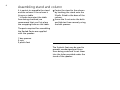
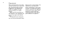
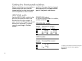
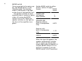
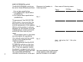
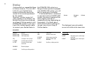
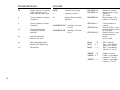
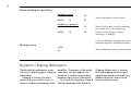
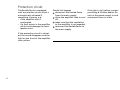
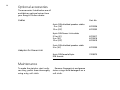
B E O L A B
P E N T A
2
For the UK market only:
IMPORTANT!
The wires in the mains lead supplied with
this apparatus are coloured in accordance
with the following code:
BLUE: NEUTRAL
BROWN: LIVE
As the colours of the wires in the mains
lead of this apparatus may not correspond
with the coloured markings identifying the
terminals in your plug, proceed as follows:
- The wire which is coloured blue must be
connected to the terminal which is
marked with the letter N or coloured
BLACK.
- The wire which is coloured brown must
be connected to the terminal which is
marked with the letter L or coloured
RED.
Ensure that your equipment is connected
correctly. If you are in any doubt, consult a
qualified electrician.
For the US market only:
CAUTION
RISK OF ELECTRIC SHOCK
DO NOT OPEN
CAUTION: To reduce the risk
of electric shock, do not
remove cover (or back).
No user-serviceable parts
inside. Refer servicing to
qualified service personnel.
WARNING: To prevent fire or
electric shock, do not expose
this appliance to rain or
moisture.
This symbol indicates that a
dangerous voltage constituting a risk of electric shock is
present within this unit.
This symbol indicates that
there are important operating and maintenance instructions in the literature accompanying this unit.
This equipment generates and uses radio
frequency energy and if not installed and
used properly, that is, in strict accordance
with the manufacturer’s instructions, may
cause interference to radio and television
reception. It has been type tested and
found to comply with the limits for a Class
B computing device in accordance with
the specifications in Subpart J of Part 15
of FCC Rules, which are designed to provide reasonable protection against such
interference in a residential installation.
However, there is no guarantee that interference will not occur in a particular
installation. If this equipment does cause
interference to radio or television reception, which can be determined by turning
the equipment off and on, the user is
encouraged to try to correct the interference by one or more of the following
measures:
- Reorient the receiving antenna
- Relocate the computer with respect to the
receiver
- Move the computer away from the receiver
- Plug the computer into a different outlet
so that computer and receiver are on
different branch circuits.
If necessary, the user should consult the
dealer or an experienced radio/television
technician for additional suggestions. The
user may find the following booklet prepared by the Federal Communications Commission helpful:
“How to Identify and Resolve Radio-TV
Interference Problems”.
This booklet is available from the U.S.
Government Printing Office, Washington,
DC 20402, Stock No. 004-00345-4.
TABLE OF CONTENTS
6 Assembling stand and column
7 Connections
10 Placement
11 Setting the front panel switches
14 Display
16 Dynamic Clipping Attenuator
17 Protection circuit
18 Optional accessories
18 Maintenance
19 International guarantee
3
Your Beolab Penta is the top of the line in the Bang &
Olufsen range of audio equipment. It consists of the best
Bang & Olufsen loudspeaker and amplifier ever, united in a
slim, pentagonal sound column with stainless steel finish.
Owing to its sculptural design, the Beolab Penta takes up
very little floor space. It adopts the colour of its surroundings
and enhances the beauty of your home while giving you
extraordinary musical experiences. The Beolab Penta
consists of a loudspeaker unit matched by a powerful, fully
automatic one-channel amplifier. The amplifier unit is
equipped with the Dynamic Clipping Attenuator which
reduces any audible distortion. The speaker unit contains a
display which gives you useful information about the current
state of your audio or video system.
This manual describes how to assemble the Beolab Penta,
where to place it and how to connect and adjust it to your
Bang & Olufsen audio or video system.
6
Assembling stand and column
It is easiest to assemble the stand
and the column if the column is
lying on a table.
In order to protect the table
from being scratched, we
recommend that you first place
the wrapping foam on the table.
Fasten the stand to the column
by hooking the stand onto the
5 bolts fitted to the base of the
column.
Screw the 5 nuts onto the bolts
and tighten them securely using
the box spanner.
The parts required for assembling
the Beolab Penta are supplied
with the speaker:
1 box spanner
5 nuts
5 plastic feet
The 5 plastic feet may be used to
prevent wooden/parquet floors
from being scratched. Insert them
into the holes provided under the
stand of the speaker.
Connections
The Beolab Penta can be
connected to either a receiver, a
TV set, a Master Control Link 2 A
or a Master Control Link 2 AV
(MCL 2 A/2 AV).
For lengths and parts numbers
of the cables which can be used,
see the section “Optional accessories”.
NOTE! Before connecting the
Beolab Penta to the receiver, TV
set or MCL 2 A/2 AV, make sure
that the MODE switch on the
front panel is set to OFF. This
precaution applies to both the
initial set-up and to later rearrangements of connections.
Do not switch on your audio or
video system until you have set the
switches on the front panel to their
correct position (see pp 11-13).
Connection to a Bang & Olufsen receiver or TV set or an MCL 2 A/2 AV
When connecting your Beolab
Penta, you may use either the
POWER LINK socket or the
SPEAKER LINK socket.
POWER LINK 1 & POWER LINK 2
sockets
(using an 8-pin DIN Power Link
cable).
The sockets marked POWER
LINK 1 & 2 are identical. This
means that either socket can be
used when you connect your
Beolab Penta by means of a
Power Link cable.
7
POWER LINK 1
Plug one end of the cable into
one of the POWER LINK sockets
on the Beolab Penta.
Plug the other end of the cable
into one of the POWER LINK
sockets on your receiver, TV set
or MCL 2 AV.
Repeat the procedure for the
other speaker.
POWER LINK 2
8
In order to avoid running cables
from both speakers to your receiver, TV set or MCL 2 AV, you may
loop the signal through as illustrated:
Using one Power Link cable,
connect one speaker to your
receiver, TV set or MCL 2 AV.
Using the other Power Link
cable, connect the speakers to
one another.
SPEAKER LINK socket
(using a shielded cable with 2-pin,
3-pin or 4-pin DIN speaker plugs)
Plug one end of the cable into
the SPEAKER LINK socket on the
Beolab Penta.
Plug the other end of the cable
into the appropriate socket on
your receiver, TV set or MCL 2
A/2 AV.
Repeat the procedure for the
other speaker.
AUDIO/VIDEO switch
In order to obtain the correct
status reading from the display,
the AUDIO/VIDEO switch must be
set to the correct position:
AUDIO if the Beolab Penta is
connected to a Beomaster,
Beocenter or MCL 2 A/2 AV.
VIDEO if the Beolab Penta is
connected to a Beovision.
SPEAKER LINK
Connection to other receivers
When connecting your Beolab
Penta, you may use either the
SPEAKER LINK socket or the LINE
IN socket.
9
SPEAKER LINK
SPEAKER LINK socket
(using a shielded cable with 2-pin
DIN speaker plugs)
Plug one end of the cable into
the SPEAKER LINK socket on the
Beolab Penta.
Plug the other end of the cable
into the appropriate
loudspeaker socket on the
receiver.
Repeat the procedure for the
other speaker.
LINE IN socket
(using a shielded cable with
phono plugs)
Plug the appropriate cable end
into the LINE IN socket on the
Beolab Penta.
Plug the other end of the cable
into the appropriate phono
socket (pre-amplifier output) on
your receiver.
Repeat the procedure for the
other speaker.
LINE IN
10
Placement
When the Beolab Penta has been
securely fastened to its stand and
the connecting cable has been
plugged into the appropriate
socket, the speaker must be
placed vertically on a stable
surface.
Make sure that ventilation to
the amplifier is not impeded, and
do not lean against the Beolab
Penta.
The Beolab Penta is designed
for use in dry environments only!
Because of its unique design, the
Beolab Penta can be placed
almost everywhere in your room.
However, the ideal sound performance is achieved if the speakers
are placed 3 metres apart and if
there are 3 metres from the
listening position to the centre
point between the speakers.
Setting the front panel switches
Before switching on your audio or
video system you must set the
three switches on the front panel
of the amplifier to their correct
position. To open the front panel,
press gently on the upper middle
part of the panel and release.
INPUT LEVEL switch
Set the INPUT LEVEL switch to the
position required to match the
Beolab Penta to the output of
your receiver or TV set. If in doubt
about your receiver/TV output,
consult your Bang & Olufsen
dealer.
POWER LINK socket:
If you are using Power Link cables,
set the switch to
.
SPEAKER LINK socket:
Switch Receiver/TV output*
position 4 ohm
8 ohm
40 - 40 W
40 - 80 W
80 - 80 W
40 - 20 W
20 - 40 W
40 - 80 W
LINE IN socket:
Switch Pre-amplifier output
position
1.4 - 1.4 V
1.4 - 1.4 V
1.4 - 1.4 V
11
* 4 ohms and 8 ohms receiver/TV output
specified for 4 and 8 ohms speaker
impedance.
12
MODE switch
Once connected to the mains supply, the Beolab Penta is in the
stand-by mode. The stand-by
mode is indicated by a red light
on the front of the amplifier unit.
The speaker switches on automatically when it receives a signal,
unless, of course, the MODE
switch is set to OFF. When the
speaker switches on, the light on
the front of the amplifier turns
green.
Set the MODE switch to either
AUTO, L (left) or R (right):
MODE
Sockets
switch
POWER LINK
Left speaker
Right speaker
SPEAKER LINK
Receiver without
built-in loudspeaker
relay
Receiver with
built-in loudspeaker
relay
LINE IN
L
R
AUTO
L/R
AUTO
When the signal disappears, the
speaker automatically switches
off, i.e. reverts to the stand-by
mode, after a delay of approx. 10
seconds (MODE switch in L or R
position) or approx. 3 minutes
(MODE switch in AUTO position).
BASS EXTENSION switch
The BASS EXTENSION switch can
be set to three different positions:
Placement of speaker in
listening room:
Floor area of listening room:
<30m2
III for no bass equalization
III for medium bass equalization
(+3dB/40 Hz)
III for maxium bass equalization
(+6dB/40 Hz)
13
The purpose of the BASS EXTENSION switch is to ensure that the
bass level suits the environment
and the placement of the speaker.
Which switch position to choose
depends on the distance from the
loudspeaker to corners and walls
and on the floor area of your
room.
The examples given in the table
are only meant as a guideline.
You may of course set the switch
to any of the three positions
which you prefer.
We recommend that the BASS
EXTENSION switches on the two
speakers be set to the same position. If the two speakers cannot
be placed in comparatively similar
positions related to room boundaries, both BASS EXTENSION
switches should be set to the posi-
30-50m2
Pos. 1
Pos. 2
Pos. 3
(30m2 ∼ 300 sq feet; 50m2 ∼ 500 sq feet
60 cm ∼ 2’)
tion prescribed by the placement
of the speaker with the lowest
position number in the table.
>50m2
14
Display
If connected to a compatible Bang
& Olufsen receiver, TV set or MCL
2 A/2 AV, your Beolab Penta
displays information about the
source of the sound reproduced
by the speaker.
However, in order to give full
status reading in the display, the
Beolab Penta must be connected
to a Bang & Olufsen product with
POWER LINK sockets. If you use a
4-pin DIN shielded speaker cable
to connect your Beolab Penta to
the SPEAKER LINK socket on a
Bang & Olufsen product equipped
with POWER LINK sockets, you still
get full reading in the display.
If the Beolab Penta is connected
Source
Program
Volume
to a product without POWER LINK
Track
sockets, the status reading will be
either slightly reduced or
completely missing, depending on
the product. If in doubt about
which kind of status reading you
can get, consult your Bang &
The displayed cues and symbols
Olufsen dealer.
are not all visible at the same time.
SOURCE
RADIO
RADIO FM
RADIO AM
Radio
FM broadcast
AM broadcast
CD
Compact disc player
A.TAPE
A.TP2
Audio tape recorder
Second audio tape
recorder
PHONO
Record player
A.AUX
Auxiliary audio product
TV
SAT
Television
Satellite television
V.TAPE
V.TP2
Video tape recorder
Second video tape
recorder
V.AUX
Auxiliary video product
Recording:
A-REC
V-REC
Recording on audio tape
recorder
Recording on video tape
recorder
PROGRAM/TRACK
VOLUME
10
Preset radio or TV station;
Track number on CD,
audio tape or video tape
00-98
Volume level range
-- --
Speakers muted
>
Tuning towards a higher
frequency
><
Equal balance in both
speakers
<
Tuning towards a lower
frequency
<>
The highest/lowest
frequency has been
reached
BALANCE ><
BALANCE > 1
BALANCE 1<
CNT-BAL < >
LOUDNESS OFF Loudness function
cut out
LOUDNESS ON
Loudness function
cut in
CNT-BAL <1>
CNT-BAL >1<
>>
Winding forwards
towards the end
<<
Rewinding backwards
towards the beginning
BASS
BASS
0
+ 1
<>
Pause/stop
BASS
– 1
TREBLE
0
TREBLE + 1
TREBLE – 1
15
Balance is neutral
More sound in right
speaker
(>1 to >9)
More sound in left
speaker (1< to 9 <)
Center balance is
neutral
Sound shifted 1 step
outwards from center
(<1> to <9>)
Sound shifted 1 step
inwards towards
center
(>1< to >9<)
Bass is neutral
Bass 1 step above
neutral (+1 to +6)
Bass 1 step below
neutral (–1 to –6)
Treble is neutral
Treble 1 step above
neutral (+1 to +6)
Treble 1 step below
neutral (–1 to –6)
16
Status reading on recording
Recording pause:
A-REC
22
RADIO
22
Shown alternately at short intervals
10
Recording in progress:
A-REC
22
Shown for 5 seconds after the recording
has started and is then followed by
RADIO
22
Remains in the display as long as
recording is in progress
10
If, during a recording, you adjust the sound,
the above sequence is repeated afterwards.
Missing source
LOAD
Shown alternately 3 times at short intervals
CD
Dynamic Clipping Attenuator
The Beolab Penta features a special circuit called Dynamic Clipping
Attenuator.
Clipping is a form of output
signal distortion which occurs in
cases of severe overloading of the
amplifier. The peaks of the audio
waveform will be clipped if an
amplifier is unable to reproduce
extreme input levels (transients).
To resolve this problem, Bang &
Olufsen developed the Dynamic
Clipping Attenuator. It ensures
that the clipping of the output
signal takes place with much less
audible distortion than would
otherwise be the case.
Protection circuit
The Beolab Penta is equipped
with a protection circuit which is
automatically activated if
something is wrong, e.g.
– if the amplifier unit is
overheated,
– if a fault occurs in the amplifier
which could damage the loudspeaker units.
If the protection circuit is activated, the sound disappears and the
light on the front of the amplifier
turns yellow.
17
Should this happen
disconnect the Beolab Penta
from the mains supply,
allow the amplifier time to cool
off,
make sure that the ventilation
to the amplifier is not impeded,
reconnect the Beolab Penta to
the mains supply.
If the light is still yellow, contact
your Bang & Olufsen dealer. Do
not cut the power supply in and
out several times in a row.
18
Optional accessories
The accessories listed below are all
available as optional extras from
your Bang & Olufsen dealer.
Part No
Cables
4-pin DIN shielded speaker cables
5 m (16’)
10 m (33’)
6270336
6270352
8-pin DIN Power Link cables
2.5 m (8’)
5 m (16’)
10 m (33’)
6270417
6270418
6270419
2-pin DIN shielded speaker cable
5 m (16’)
6270350
Adaptor for Power Link
8-pin DIN female/8-pin
DIN female
Maintenance
To make the stainless steel surfaces shiny, polish them thoroughly
using a dry, soft cloth.
Remove fingerprints and grease
stains using a mild detergent on a
soft cloth.
7229075
International guarantee
This Bang & Olufsen product carries a guarantee against defects in
workmanship and materials. The
terms of the guarantee apply to
the country of purchase but will
be met by authorized Bang &
Olufsen dealers in other countries.
The guarantee period applying to
the country of purchase takes
priority over guarantee periods
applying in other countries, even
where differences exist.
In order to obtain service under
this guarantee, a certificate
stating the following information
is required:
– Name of product and type
number
– Serial number
– Date of purchase
– Guarantee period
– Dealer’s or supplier’s signature
19
3506182
0982
Printed in Denmark by Bogtrykkergården a-s, Struer