1
Site Preparation Guide
REFERENCE
86 A1 87EF 08
NOVASCALE
NovaScale
Servers
BLANK
NOVASCALE
NovaScale Servers
Site Preparation Guide
Hardware
December 2006
BULL CEDOC
357 AVENUE PATTON
B.P.20845
49008 ANGERS CEDEX 01
FRANCE
REFERENCE
86 A1 87EF 08
The following copyright notice protects this book under Copyright laws which prohibit such actions as, but not
limited to, copying, distributing, modifying, and making derivative works.
Copyright
Bull SAS 1992, 2006
Printed in France
Suggestions and criticisms concerning the form, content, and presentation of this
book are invited. A form is provided at the end of this book for this purpose.
To order additional copies of this book or other Bull Technical Publications, you
are invited to use the Ordering Form also provided at the end of this book.
Trademarks and Acknowledgements
We acknowledge the right of proprietors of trademarks mentioned in this book.
Intel
and Itanium
Windows
are registered trademarks of Intel Corporation.
and Microsoft software
are registered trademarks of Microsoft Corporation.
UNIX is a registered trademark in the United States of America and other countries licensed exclusively through
the Open Group.
Linux
is a registered trademark of Linus Torvalds.
The information in this document is subject to change without notice. Bull will not be liable for errors contained
herein, or for incidental or consequential damages in connection with the use of this material.
Preface
Table of Contents
Preface . . . . . . . . . . . . . . . . . . . . . . . . . . . . . . . . . . . . . . . . . . . . . . . . . . . . . . . . . . . . . . . . .
Intended Readers . . . . . . . . . . . . . . . . . . . . . . . . . . . . . . . . . . . . . . . . . . . . . . . . . . . . . . . . .
Definition of Safety Notices . . . . . . . . . . . . . . . . . . . . . . . . . . . . . . . . . . . . . . . . . . . . . . . .
General Recommendations . . . . . . . . . . . . . . . . . . . . . . . . . . . . . . . . . . . . . . . . . . . . . . . .
Regulatory Specifications and Disclaimers . . . . . . . . . . . . . . . . . . . . . . . . . . . . . . . . . . .
Declaration of the Manufacturer or Importer . . . . . . . . . . . . . . . . . . . . . . . . . . . . . . .
Safety Compliance Statement . . . . . . . . . . . . . . . . . . . . . . . . . . . . . . . . . . . . . . . . . . . .
European Community (EC) Council Directives . . . . . . . . . . . . . . . . . . . . . . . . . . . . . .
Electromagnetic Compatibility . . . . . . . . . . . . . . . . . . . . . . . . . . . . . . . . . . . . . . .
Low Voltage . . . . . . . . . . . . . . . . . . . . . . . . . . . . . . . . . . . . . . . . . . . . . . . . . . . . . .
EC Conformity . . . . . . . . . . . . . . . . . . . . . . . . . . . . . . . . . . . . . . . . . . . . . . . . . . . .
Telecommunications Terminal Equipment . . . . . . . . . . . . . . . . . . . . . . . . . . . . . .
Federal Communications Commission (FCC) Statement . . . . . . . . . . . . . . . . . . . . . .
FCC Declaration of Conformity . . . . . . . . . . . . . . . . . . . . . . . . . . . . . . . . . . . . . . . . . .
Canadian Compliance Statement (Industry Canada) . . . . . . . . . . . . . . . . . . . . . . . .
Electromagnetic Compatibility . . . . . . . . . . . . . . . . . . . . . . . . . . . . . . . . . . . . . . .
Laser Compliance Notice . . . . . . . . . . . . . . . . . . . . . . . . . . . . . . . . . . . . . . . . . . . . . . .
Environmental Standards . . . . . . . . . . . . . . . . . . . . . . . . . . . . . . . . . . . . . . . . . . . . . . . . . .
Climatic and Atmospheric Specifications . . . . . . . . . . . . . . . . . . . . . . . . . . . . . . . . . .
Electrical Specifications . . . . . . . . . . . . . . . . . . . . . . . . . . . . . . . . . . . . . . . . . . . . . . . . .
Mains Source Power . . . . . . . . . . . . . . . . . . . . . . . . . . . . . . . . . . . . . . . . . . . . . .
Voltage Sag . . . . . . . . . . . . . . . . . . . . . . . . . . . . . . . . . . . . . . . . . . . . . . . . . . . . . .
Electromagnetic Compatibility . . . . . . . . . . . . . . . . . . . . . . . . . . . . . . . . . . . . . . . . . . .
Bull NovaScale Blade servers also comply with standards: . . . . . . . . . . . . . .
Protection against Electrostatic Discharges . . . . . . . . . . . . . . . . . . . . . . . . . . . . . . . . .
Shocks and Vibrations . . . . . . . . . . . . . . . . . . . . . . . . . . . . . . . . . . . . . . . . . . . . . . . . . .
Operating Mode (on levelers) . . . . . . . . . . . . . . . . . . . . . . . . . . . . . . . . . . . . . . .
Non-operating Mode (on castors) . . . . . . . . . . . . . . . . . . . . . . . . . . . . . . . . . . .
Shock Tests: . . . . . . . . . . . . . . . . . . . . . . . . . . . . . . . . . . . . . . . . . . . . . . . . . . . . . .
Pollution Limits . . . . . . . . . . . . . . . . . . . . . . . . . . . . . . . . . . . . . . . . . . . . . . . . . . . . . . . . .
Audio-Noise Limits . . . . . . . . . . . . . . . . . . . . . . . . . . . . . . . . . . . . . . . . . . . . . . . . . . . . .
Operating LwAd Acoustical Power . . . . . . . . . . . . . . . . . . . . . . . . . . . . . . . . . .
Operating Lpa Acoustical Pressure . . . . . . . . . . . . . . . . . . . . . . . . . . . . . . . . . .
Safety Specifications . . . . . . . . . . . . . . . . . . . . . . . . . . . . . . . . . . . . . . . . . . . . . . . . . . .
iii
ix
ix
x
xi
xi
xi
xi
xi
xi
xi
xi
xii
xii
xii
xii
xii
xiii
xiii
xiii
xiii
xiii
xiii
xiii
xiv
xiv
xiv
xiv
xiv
xv
xv
xv
xv
xv
Chapter 1. General Requirements . . . . . . . . . . . . . . . . . . . . . . . . . . . . . . . . . . . . . . . . . . .
Server Cabinets . . . . . . . . . . . . . . . . . . . . . . . . . . . . . . . . . . . . . . . . . . . . . . . . . . . . . . . . . .
Delivery Conditions . . . . . . . . . . . . . . . . . . . . . . . . . . . . . . . . . . . . . . . . . . . . . . . . . . . . . . .
Carry-In Route . . . . . . . . . . . . . . . . . . . . . . . . . . . . . . . . . . . . . . . . . . . . . . . . . . . . . . . . . . .
Unpacking Requirements . . . . . . . . . . . . . . . . . . . . . . . . . . . . . . . . . . . . . . . . . . . . . . . . . .
1-1
1-1
1-2
1-2
1-3
Preface
iii
Chapter 2. Fitting out the Premises . . . . . . . . . . . . . . . . . . . . . . . . . . . . . . . . . . . . . . . . . .
Data Processing Center Layout . . . . . . . . . . . . . . . . . . . . . . . . . . . . . . . . . . . . . . . . . . . . .
Planning Installation . . . . . . . . . . . . . . . . . . . . . . . . . . . . . . . . . . . . . . . . . . . . . . . . . . . . . .
Cable Cut-outs . . . . . . . . . . . . . . . . . . . . . . . . . . . . . . . . . . . . . . . . . . . . . . . . . . . . . . . . .
Power Cables . . . . . . . . . . . . . . . . . . . . . . . . . . . . . . . . . . . . . . . . . . . . . . . . . . . . . . . . .
Network Cables . . . . . . . . . . . . . . . . . . . . . . . . . . . . . . . . . . . . . . . . . . . . . . . . . . . . . . .
Service Clearance . . . . . . . . . . . . . . . . . . . . . . . . . . . . . . . . . . . . . . . . . . . . . . . . . . . . .
Electrical / Electromagnetic Interference . . . . . . . . . . . . . . . . . . . . . . . . . . . . . . . . . . . . .
Fire Protection . . . . . . . . . . . . . . . . . . . . . . . . . . . . . . . . . . . . . . . . . . . . . . . . . . . . . . . . . . .
Fire Detection . . . . . . . . . . . . . . . . . . . . . . . . . . . . . . . . . . . . . . . . . . . . . . . . . . . . . . . . .
Extinguishing Procedure . . . . . . . . . . . . . . . . . . . . . . . . . . . . . . . . . . . . . . . . . . . . . . . .
Extinguishing Agents . . . . . . . . . . . . . . . . . . . . . . . . . . . . . . . . . . . . . . . . . . . . . . . . . . .
Alarms . . . . . . . . . . . . . . . . . . . . . . . . . . . . . . . . . . . . . . . . . . . . . . . . . . . . . . . . . . . . . . .
Water Damage . . . . . . . . . . . . . . . . . . . . . . . . . . . . . . . . . . . . . . . . . . . . . . . . . . . . . . . . . .
Computer Room Floor . . . . . . . . . . . . . . . . . . . . . . . . . . . . . . . . . . . . . . . . . . . . . . . . . . . . .
Primary Floor . . . . . . . . . . . . . . . . . . . . . . . . . . . . . . . . . . . . . . . . . . . . . . . . . . . . . . . . . .
Raised Floor . . . . . . . . . . . . . . . . . . . . . . . . . . . . . . . . . . . . . . . . . . . . . . . . . . . . . . . . . .
Raised Floor Features: . . . . . . . . . . . . . . . . . . . . . . . . . . . . . . . . . . . . . . . . . . . . .
Computer Room Ceiling . . . . . . . . . . . . . . . . . . . . . . . . . . . . . . . . . . . . . . . . . . . . . . . . . . .
Suspended Ceiling . . . . . . . . . . . . . . . . . . . . . . . . . . . . . . . . . . . . . . . . . . . . . . . . . . . . .
Suspended Ceiling Features: . . . . . . . . . . . . . . . . . . . . . . . . . . . . . . . . . . . . . . . .
Sound-Proofing . . . . . . . . . . . . . . . . . . . . . . . . . . . . . . . . . . . . . . . . . . . . . . . . . . . . . . . . . .
Protection from Sunlight . . . . . . . . . . . . . . . . . . . . . . . . . . . . . . . . . . . . . . . . . . . . . . . . . . .
Cleaning . . . . . . . . . . . . . . . . . . . . . . . . . . . . . . . . . . . . . . . . . . . . . . . . . . . . . . . . . . . . . . . .
Media Storage Room . . . . . . . . . . . . . . . . . . . . . . . . . . . . . . . . . . . . . . . . . . . . . . . . . . . . .
Paper Storage Room . . . . . . . . . . . . . . . . . . . . . . . . . . . . . . . . . . . . . . . . . . . . . . . . . . . . . .
Printing Room . . . . . . . . . . . . . . . . . . . . . . . . . . . . . . . . . . . . . . . . . . . . . . . . . . . . . . . . . . . .
Ancillary Equipment Room . . . . . . . . . . . . . . . . . . . . . . . . . . . . . . . . . . . . . . . . . . . . . . . . .
2-1
2-1
2-3
2-3
2-3
2-4
2-5
2-7
2-7
2-7
2-7
2-8
2-8
2-8
2-9
2-9
2-9
2-9
2-10
2-10
2-10
2-11
2-11
2-11
2-12
2-12
2-12
2-12
Chapter 3. Air-Conditioning . . . . . . . . . . . . . . . . . . . . . . . . . . . . . . . . . . . . . . . . . . . . . . . .
Air-Conditioning System Features and Functions . . . . . . . . . . . . . . . . . . . . . . . . . . . . . .
Features . . . . . . . . . . . . . . . . . . . . . . . . . . . . . . . . . . . . . . . . . . . . . . . . . . . . . . . . . . . . . .
Functions . . . . . . . . . . . . . . . . . . . . . . . . . . . . . . . . . . . . . . . . . . . . . . . . . . . . . . . . . . . . .
Temperature Control . . . . . . . . . . . . . . . . . . . . . . . . . . . . . . . . . . . . . . . . . . . . . . .
Hygrometry Control . . . . . . . . . . . . . . . . . . . . . . . . . . . . . . . . . . . . . . . . . . . . . . .
Heat Dissipation . . . . . . . . . . . . . . . . . . . . . . . . . . . . . . . . . . . . . . . . . . . . . . . . . .
Air-Conditioning System Specifications . . . . . . . . . . . . . . . . . . . . . . . . . . . . . . . . . . . . . .
Air Renewal, Distribution, Circulation, Pollution, and Filtering . . . . . . . . . . . . . . . .
Renewal . . . . . . . . . . . . . . . . . . . . . . . . . . . . . . . . . . . . . . . . . . . . . . . . . . . . . . . . .
Distribution . . . . . . . . . . . . . . . . . . . . . . . . . . . . . . . . . . . . . . . . . . . . . . . . . . . . . . .
Circulation . . . . . . . . . . . . . . . . . . . . . . . . . . . . . . . . . . . . . . . . . . . . . . . . . . . . . . .
Pollutants . . . . . . . . . . . . . . . . . . . . . . . . . . . . . . . . . . . . . . . . . . . . . . . . . . . . . . . .
Checks and Alarms . . . . . . . . . . . . . . . . . . . . . . . . . . . . . . . . . . . . . . . . . . . . . . . . . . . . . . .
3-1
3-1
3-1
3-1
3-1
3-1
3-1
3-2
3-2
3-2
3-2
3-3
3-4
3-5
Chapter 4. Power Supply . . . . . . . . . . . . . . . . . . . . . . . . . . . . . . . . . . . . . . . . . . . . . . . . . .
4-1
Power Supply . . . . . . . . . . . . . . . . . . . . . . . . . . . . . . . . . . . . . . . . . . . . . . . . . . . . . . . . . . . .
4-1
Prerequisites: . . . . . . . . . . . . . . . . . . . . . . . . . . . . . . . . . . . . . . . . . . . . . . . . . . . . .
4-1
Cabling Requirements . . . . . . . . . . . . . . . . . . . . . . . . . . . . . . . . . . . . . . . . . . . . . . . . . . . . .
4-2
Mounting Power Supply Cable Sockets . . . . . . . . . . . . . . . . . . . . . . . . . . . . . . . . . . . . . .
4-3
Tools Required . . . . . . . . . . . . . . . . . . . . . . . . . . . . . . . . . . . . . . . . . . . . . . . . . . . .
4-3
Europe, Brazil . . . . . . . . . . . . . . . . . . . . . . . . . . . . . . . . . . . . . . . . . . . . . . . . . . . .
4-3
United States of America . . . . . . . . . . . . . . . . . . . . . . . . . . . . . . . . . . . . . . . . . . .
4-3
Grounding Circuit . . . . . . . . . . . . . . . . . . . . . . . . . . . . . . . . . . . . . . . . . . . . . . . . . . . . . . . .
4-5
Electric protection wire characteristics (in compliance with Standard NFC 15.100): .
4-5
iv
Site Preparation Guide
Grounding the Raised Floor . . . . . . . . . . . . . . . . . . . . . . . . . . . . . . . . . . . . . . . . . . . . .
Neutral Power System . . . . . . . . . . . . . . . . . . . . . . . . . . . . . . . . . . . . . . . . . . . . . . . . . . . .
Constructing a TN-S Neutral Point Connection System . . . . . . . . . . . . . . . . . . . . . . .
Non-Computing Power Supply . . . . . . . . . . . . . . . . . . . . . . . . . . . . . . . . . . . . . . . . . . . . .
Prerequisites . . . . . . . . . . . . . . . . . . . . . . . . . . . . . . . . . . . . . . . . . . . . . . . . . . . . . .
Ambient Lighting . . . . . . . . . . . . . . . . . . . . . . . . . . . . . . . . . . . . . . . . . . . . . . . . . . . . . . .
Emergency Lighting . . . . . . . . . . . . . . . . . . . . . . . . . . . . . . . . . . . . . . . . . . . . . . . . . . . .
4-5
4-6
4-6
4-8
4-8
4-8
4-8
Appendix A. Specifications . . . . . . . . . . . . . . . . . . . . . . . . . . . . . . . . . . . . . . . . . . . . . . . .
NovaScale Blade 2xxx Cabinet Specifications . . . . . . . . . . . . . . . . . . . . . . . . . . . . . . .
NovaScale Blade 20xx Chassis Specifications . . . . . . . . . . . . . . . . . . . . . . . . . . . . . . .
NovaScale Blade 2020 Server Specifications . . . . . . . . . . . . . . . . . . . . . . . . . . . . . . . .
NovaScale Blade 2021 Server Specifications . . . . . . . . . . . . . . . . . . . . . . . . . . . . . . . .
NovaScale Blade 2040 Server Specifications . . . . . . . . . . . . . . . . . . . . . . . . . . . . . . . .
NovaScale Blade 2320 Server Specifications . . . . . . . . . . . . . . . . . . . . . . . . . . . . . . . .
NovaScale 3005 Series Server Cabinet Specifications . . . . . . . . . . . . . . . . . . . . . . . .
Novascale 3025 Server CPU Drawer Specifications . . . . . . . . . . . . . . . . . . . . . . . . . .
NovaScale 3045 Server CPU Drawer Specifications . . . . . . . . . . . . . . . . . . . . . . . . . .
NovaScale 3045 COMPACT Server CPU Drawer Specifications . . . . . . . . . . . . . . . .
NovaScale 4020/4040 Server Cabinet Specifications . . . . . . . . . . . . . . . . . . . . . . . .
........................................................................
NovaScale 4020 Server CPU Drawer Specifications . . . . . . . . . . . . . . . . . . . . . . . . . .
NovaScale 4040 Server CPU Drawer Specifications . . . . . . . . . . . . . . . . . . . . . . . . . .
NovaScale 5080/5160/6080/6160 Specifications . . . . . . . . . . . . . . . . . . . . . . . . .
NovaScale 5320/6320 Server Specifications . . . . . . . . . . . . . . . . . . . . . . . . . . . . . . . .
NovaScale 5085 Server Specifications . . . . . . . . . . . . . . . . . . . . . . . . . . . . . . . . . . . . . .
NovaScale 5165 Server Specifications . . . . . . . . . . . . . . . . . . . . . . . . . . . . . . . . . . . . . .
NovaScale 5245 Server Specifications . . . . . . . . . . . . . . . . . . . . . . . . . . . . . . . . . . . . . .
NovaScale 5325 Server Specifications . . . . . . . . . . . . . . . . . . . . . . . . . . . . . . . . . . . . . .
Smart UPS References . . . . . . . . . . . . . . . . . . . . . . . . . . . . . . . . . . . . . . . . . . . . . . . . . . . . .
A-1
A-2
A-4
A-5
A-5
A-5
A-6
A-7
A-9
A-10
A-11
A-12
A-12
A-14
A-15
A-16
A-18
A-20
A-22
A-24
A-26
A-28
Appendix B. Conversion Tables . . . . . . . . . . . . . . . . . . . . . . . . . . . . . . . . . . . . . . . . . . . . .
Imperial to Metric . . . . . . . . . . . . . . . . . . . . . . . . . . . . . . . . . . . . . . . . . . . . . . . . . . .
Metric to Imperial . . . . . . . . . . . . . . . . . . . . . . . . . . . . . . . . . . . . . . . . . . . . . . . . . . .
Celsius to Fahrenheit Conversion . . . . . . . . . . . . . . . . . . . . . . . . . . . . . . . . . . . . . .
Fahrenheit to Celsius Conversion . . . . . . . . . . . . . . . . . . . . . . . . . . . . . . . . . . . . . .
B-1
B-1
B-1
B-2
B-2
Index . . . . . . . . . . . . . . . . . . . . . . . . . . . . . . . . . . . . . . . . . . . . . . . . . . . . . . . . . . . . . . . . . . .
X-1
Preface
v
vi
Site Preparation Guide
List of Figures
Figure
Figure
Figure
Figure
Figure
Figure
Figure
Figure
Figure
Figure
Figure
Figure
Figure
Figure
Figure
Figure
1.
2.
3.
4.
5.
6.
7.
8.
9.
10.
11.
12.
13.
14.
15.
16.
Bull server cabinets . . . . . . . . . . . . . . . . . . . . . . . . . . . . . . . . . . . . . . . . . . . . . . . . . . . . . . . . . .
Required unpacking area . . . . . . . . . . . . . . . . . . . . . . . . . . . . . . . . . . . . . . . . . . . . . . . . . . . . .
Recommended Data Processing Center layout . . . . . . . . . . . . . . . . . . . . . . . . . . . . . . . . . . . .
Cabinet cable cut-outs . . . . . . . . . . . . . . . . . . . . . . . . . . . . . . . . . . . . . . . . . . . . . . . . . . . . . . . .
Single cabinet service clearance . . . . . . . . . . . . . . . . . . . . . . . . . . . . . . . . . . . . . . . . . . . . . . .
Dual cabinet service clearance . . . . . . . . . . . . . . . . . . . . . . . . . . . . . . . . . . . . . . . . . . . . . . . .
Layout grid . . . . . . . . . . . . . . . . . . . . . . . . . . . . . . . . . . . . . . . . . . . . . . . . . . . . . . . . . . . . . . . . .
Raised floor cross-section . . . . . . . . . . . . . . . . . . . . . . . . . . . . . . . . . . . . . . . . . . . . . . . . . . . . .
Raised floor structure . . . . . . . . . . . . . . . . . . . . . . . . . . . . . . . . . . . . . . . . . . . . . . . . . . . . . . . . .
Example of poor air distribution . . . . . . . . . . . . . . . . . . . . . . . . . . . . . . . . . . . . . . . . . . . . . . .
Example of obstacles that may obstruct air circulation . . . . . . . . . . . . . . . . . . . . . . . . . . . . .
Plug and socket . . . . . . . . . . . . . . . . . . . . . . . . . . . . . . . . . . . . . . . . . . . . . . . . . . . . . . . . . . . . .
US plug characteristics . . . . . . . . . . . . . . . . . . . . . . . . . . . . . . . . . . . . . . . . . . . . . . . . . . . . . . .
PDU/UPS Power socket . . . . . . . . . . . . . . . . . . . . . . . . . . . . . . . . . . . . . . . . . . . . . . . . . . . . . . .
Raised floor equipotentiality method . . . . . . . . . . . . . . . . . . . . . . . . . . . . . . . . . . . . . . . . . . . .
Grounding circuit diagram for a TN-S neutral point connection . . . . . . . . . . . . . . . . . . . . .
Preface
1-1
1-3
2-2
2-3
2-5
2-5
2-6
2-9
2-10
3-3
3-3
4-3
4-3
4-4
4-6
4-7
vii
List of Tables
Table
Table
Table
Table
Table
Table
Table
Table
Table
Table
Table
Table
Table
Table
Table
Table
Table
Table
Table
Table
Table
viii
1.
2.
3.
4.
5.
6.
7.
8.
9.
10.
11.
12.
13.
14.
15.
16.
17.
18.
19.
20.
21.
NovaScale Blade 20xx cabinet specifications . . . . . . . . . . . . . . . . . . . . . . . . . . . . . . . . . . . .
NovaScale Blade 20xx Chassis specifications . . . . . . . . . . . . . . . . . . . . . . . . . . . . . . . . . . .
NovaScale Blade 2020 Server specifications . . . . . . . . . . . . . . . . . . . . . . . . . . . . . . . . . . . .
NovaScale Blade 2021 Server specifications . . . . . . . . . . . . . . . . . . . . . . . . . . . . . . . . . . . .
NovaScale Blade 2040 Server specifications . . . . . . . . . . . . . . . . . . . . . . . . . . . . . . . . . . . .
NovaScale Blade 2320 Server specifications . . . . . . . . . . . . . . . . . . . . . . . . . . . . . . . . . . . .
NovaScale 3005 Series Server Cabinet Specifications . . . . . . . . . . . . . . . . . . . . . . . . . . . .
NovaScale 3025 Server CPU drawer specifications . . . . . . . . . . . . . . . . . . . . . . . . . . . . . .
NovaScale 3045 Server CPU drawer specifications . . . . . . . . . . . . . . . . . . . . . . . . . . . . . .
NovaScale 3045 COMPACT Server CPU drawer specifications . . . . . . . . . . . . . . . . . . . .
NovaScale 4020/4040 Server cabinet specifications . . . . . . . . . . . . . . . . . . . . . . . . . . . .
NovaScale 4020 Server CPU drawer specifications . . . . . . . . . . . . . . . . . . . . . . . . . . . . . .
NovaScale 4040 Server CPU drawer specifications . . . . . . . . . . . . . . . . . . . . . . . . . . . . . .
NovaScale 5080/5160/6080/6160 Server specifications . . . . . . . . . . . . . . . . . . . . . . .
NovaScale 5320/6320 Server specifications . . . . . . . . . . . . . . . . . . . . . . . . . . . . . . . . . . .
NovaScale 5085 Server specifications . . . . . . . . . . . . . . . . . . . . . . . . . . . . . . . . . . . . . . . . . .
NovaScale 5165 Server specifications . . . . . . . . . . . . . . . . . . . . . . . . . . . . . . . . . . . . . . . . . .
NovaScale 5245 Server specifications . . . . . . . . . . . . . . . . . . . . . . . . . . . . . . . . . . . . . . . . . .
NovaScale 5325 Server specifications . . . . . . . . . . . . . . . . . . . . . . . . . . . . . . . . . . . . . . . . . .
Imperial to metric conversion table . . . . . . . . . . . . . . . . . . . . . . . . . . . . . . . . . . . . . . . . . . . . .
Metric to imperial conversion table . . . . . . . . . . . . . . . . . . . . . . . . . . . . . . . . . . . . . . . . . . . . .
Site Preparation Guide
A-3
A-4
A-5
A-5
A-5
A-6
A-8
A-9
A-10
A-11
A-13
A-14
A-15
A-17
A-19
A-21
A-23
A-25
A-27
B-1
B-1
Intended Readers
This Site Preparation Guide explains how to prepare a Data Processing Center for Bull
servers, in compliance with the standards in force. It is to be used by all personnel and trade
representatives involved in the site preparation process.
• General Recommendations
describes delivery requirements
• Chapter 2. Fitting out the Premises
describes general site layout and requirements.
• Chapter 3. Air-Conditioning
describes site air-conditioning requirements.
• Chapter 4. Power Supply
describes site power supply requirements.
• Appendix A. Specifications
• Appendix B. Conversion Tables
Definition of Safety Notices
Special attention is to be paid to the safety notices contained in this guide:
DANGER
A Danger notice indicates the presence of a hazard that could result in death or serious
personal injury.
CAUTION:
A Caution notice indicates the presence of a hazard that could result in moderate or minor
personal injury.
Warning:
A Warning notice indicates an action that could cause damage to a program, device,
system, or data.
Preface
ix
General Recommendations
It is mandatory to comply with the procedures, design requirements and recommendations set
out in this guide. The construction of the Data Processing Center and the installation of
ancillary facilities must comply with:
• the level of safety required by the standards and laws in force in the country where the
server is to be installed,
• the Customer's requirements in terms of continuity of service.
All the standards referred to in this Site Preparation Guide are applicable in France.
Equivalent standards must be applied and complied with in other countries.
Site preparation must take all the following aspects into account:
• safety of personnel,
• primary / raised floor,
• suspended ceiling,
• sound-proofing,
• protection from sunlight,
• access control,
• fire protection,
• water protection,
• air-conditioning,
• power supply.
Warning:
The installation of an "on-line" Uninterruptible Power Supply (UPS) is strongly recommended
to ensure continuity of service and to protect the system in the event of a mains failure.
On request, our local Customer Service Department can supply you with a list of the services
available for your server. These services include Data Processing Center site assessment and
conformity inspections.
Site preparation must be completed by the pre-arranged delivery date. Any delay due to
non-completion of the site by the pre-arranged date will be considered as the Customer's
responsibility.
The Customer shall bear the cost of the works to be carried out to attain stipulated safety and
continuity of operation requirements.
The following web site may be consulted for general site preparation information:
http://www.cs.bull.net/aise
x
Site Preparation Guide
Regulatory Specifications and Disclaimers
Declaration of the Manufacturer or Importer
We hereby certify that this product is in compliance with European Union EMC Directive
89/336/EEC, using standards EN55022 (Class A) and EN55024 and Low Voltage
Directive 73/23/EEC, using standard EN60950. The product has been marked with the CE
Mark to illustrate its compliance.
Safety Compliance Statement
• UL 60950 (USA)
• IEC 60950 (International)
• CSA 60950 (Canada)
European Community (EC) Council Directives
This product is in conformity with the protection requirements of the following EC Council
Directives:
Electromagnetic Compatibility
• 89/336/EEC
Low Voltage
• 73/23/EEC
EC Conformity
• 93/68/EEC
Telecommunications Terminal Equipment
• 1999/5/EC
Neither the provider nor the manufacturer can accept responsibility for any failure to satisfy
the protection requirements resulting from a non-recommended modification of the product.
Compliance with these directives requires:
• an EC declaration of conformity from the manufacturer
• an EC label on the product
• technical documentation
Preface
xi
Federal Communications Commission (FCC) Statement
Note:
This equipment has been tested and found to comply with the limits for a Class A digital
device, pursuant to Part 15 of the FCC Rules. These limits are designed to provide
reasonable protection against harmful interference when the equipment is operated in a
commercial environment. This equipment generates, uses, and can radiate radio frequency
energy and, if not installed and used in accordance with the instruction manual, may cause
harmful interference to radio communications. Operation of this equipment in a residential
area is likely to cause harmful interference in which case the user will be required to correct
the interference at his own expense.
Properly shielded and grounded cables and connectors must be used in order to meet FCC
emission limits. Neither the provider nor the manufacturer are responsible for any radio or
television interference caused by using other than recommended cables and connectors or by
unauthorized changes or modifications to this equipment. Unauthorized changes or
modifications could void the user's authority to operate the equipment.
Any changes or modifications not expressly approved by the grantee of this device could
void the user's authority to operate the equipment. The customer is responsible for ensuring
compliance of the modified product.
FCC Declaration of Conformity
This device complies with Part 15 of the FCC Rules. Operation is subject to the following two
conditions: (1) this device may not cause harmful interference, and (2) this device must
accept any interference received, including interference that may cause undesired operation.
Canadian Compliance Statement (Industry Canada)
This Class A digital apparatus meets all requirements of the Canadian Interference Causing
Equipment Regulations.
Cet appareil numérique de la classe A est conforme à la norme NMB-003 du Canada.
This product is in conformity with the protection requirements of the following standards:
Electromagnetic Compatibility
• ICES-003
• NMB-003
Laser Compliance Notice
This product that uses laser technology complies with Class 1 laser requirements.
A CLASS 1 LASER PRODUCT label is located on the laser device.
Class 1 Laser Product
Luokan 1 Laserlaite
Klasse 1 Laser Apparat
Laser Klasse 1
xii
Site Preparation Guide
Environmental Standards
Climatic and Atmospheric Specifications
The servers comply with standards:
• IEC 60068.2.1
IEC 60068.2.2
IEC 60068.2.78
IEC 60529
IEC 60950
ISO 7779
Electrical Specifications
The servers comply with standards:
• IEC
IEC
IEC
IEC
IEC
60038
60059
60196
60364
61689
Mains Source Power
• 207-244 VAC, 49 - 61 Hz (single phase Ph / N + PE or Ph / Ph + PE),
20/32/64A per PDU (see model specifications)
Voltage Sag
• 20 ms (IEC 1000-4-11)
Electromagnetic Compatibility
The servers comply with standards:
Europe:
North America
EMC Directive, 89/336/EEC
• EN55022, Class A Limit, Radiated & Conducted Emissions
• EN55024, ITE Specific Immunity Standard
• EN61000-4-2, ESD Immunity (Level 2 Contact Discharge, Level 3 Air Discharge)
• EN61000-4-3, Radiated Immunity (Level 2)
• EN61000-4-4, Electrical Fast Transient (Level 2)
• EN61000-4-5, AC Surge
• EN61000-4-6, Conducted RF
• EN61000-4-8, Power Frequency Magnetic Fields
• EN61000-4-11, Voltage Dips and Interrupts
• EN61000-3-2, Limit for Harmonic Current Emissions
• EN61000-3-3, Voltage Flicker
• FCC Part 15 Class A
• ICES-003 Issue 3 Class A
Bull NovaScale Blade servers also comply with standards:
• Japan:
IEC 1000-3-2
• Australia / New Zealand: IEC 60950
• Taiwan:
BSMI Approval
• Korea:
RRL Approval
• Russia:
GOST Approved
• International:
CISPR, Class A Limit
Preface
xiii
Protection against Electrostatic Discharges
CMOS (Complementary Metal Oxide Semiconductor) technology is highly sensitive to
electrostatic discharges. The use of conductive antistatic flooring is strongly recommended.
Maintenance personnel must wear wrist-straps before handling electronic equipment.
A ground socket is provided in each cabinet.
Shocks and Vibrations
The servers comply with standards:
IEC 60068-1
IEC 60068-2-6
IEC 60068-2-27
IEC 60068-2-31
IEC 60068-2-47
IEC 60068-2-64
IEC 60050
ISO 2041
ISO 5348
ISO 5344
ISO 8626
Operating Mode (on levelers)
• Sinusoidal vibrations:
-
Duration: 1 sweep, 1 octave/mn
-
5 - 16 Hz range: 0.25 mm peak
-
16 -200 Hz range: 0.25 g peak
• Random excitation:
-
Duration: 15 mn
-
Frequency: 5 - 200 Hz
-
Spectral density: 1.5x10⁻⁴ g /Hz
-
Root mean square acceleration: 0.17g RMS
Non-operating Mode (on castors)
• Sweep sine:
-
Duration: 1 sweep, 1 octave/mn
-
5 - 16 Hz range: 0.25 mm peak
-
16 - 200 Hz range: 0.25 g peak
• Random excitation:
-
Duration: 15 mn
-
Frequency: 5 - 200 Hz
-
Spectral density: 1.5x10⁻³ g /Hz
-
Root mean square acceleration: 0.54g RMS
Shock Tests:
• Duration: 11 ms
• Form: 1/2 sinusoidal
• Amplitude: 15 g
xiv
Site Preparation Guide
Pollution Limits
The servers comply with standard:
• NFX44-101, Class 4 000 000
Audio-Noise Limits
The servers comply with standards:
• ISO 7779
• ISO 11201
• ISO 7574
• ISO 4871
• ISO 9295
• ISO 9296
• IEC 61260
• IEC 60651 (Bull NovaScale 5xx5 Series & Bull NovaScale 5xx5 Series)
• IEC 61672-1 (Bull NovaScale 4000 Series)
• IEC 61672-2 (Bull NovaScale 4000 Series)
Operating LwAd Acoustical Power
• 7.4 Bel
Operating Lpa Acoustical Pressure
• 60 dBA
Safety Specifications
The servers comply with national and international standards:
• IEC 60950
• EN 60950
• UL 60950
• CAN/CSA C22-2 N° 60950-00
Preface
xv
xvi
Site Preparation Guide
Chapter 1. General Requirements
This chapter explains delivery and unpacking requirements for the servers.
It includes the following topics:
• Server Cabinet, on page 1-1
• Delivery Conditions, on page 1-2
• Carry-In Route, on page 1-2
• Unpacking Requirements, on page 1-3
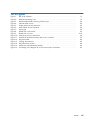
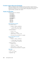
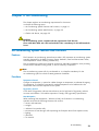
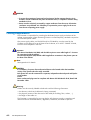
Server Cabinets
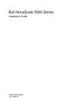
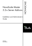
The servers are delivered rack-mounted and pre-cabled in one or two 19U / 40U cabinets,
according to the version chosen.
Figure 1.
Bull server cabinets
General Recommendations
1-1
Delivery Conditions
The server is delivered 24 hours in advance of the scheduled installation date.
On arrival, the server must be placed, in its packing, in the Computer Room so that it
reaches room temperature before powering up (optimum operating temperature = 22° C +
3° C, hygrometry = 50% + 5%).
Warning:
To avoid incorrect handling, the server must be removed from its packing by authorized
Customer Service Engineers only.
Carry-In Route
The route from the unloading bay to the Computer Room must be checked to ensure that the
server can be carried into the premises easily and that floors can support temporary
overloads during delivery. See Appendix A Specifications.
The Sales Department or local Customer Service Department will draw up an Access Sheet to
ensure correct delivery.
CAUTION:
It is mandatory for the server to be transported vertically.
The server is extremely heavy and requires the use of an elevator.
The Data Processing Site manager must allocate enough personnel to ensure safe handling of
the server.
1-2
Site Preparation Guide
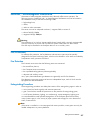
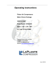
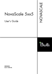
Unpacking Requirements
The cabinet is delivered packed on a pallet with rails for easy unloading.
The Data Processing Site manager must set aside the required working area for unpacking,
as shown in the following figure. See Appendix A. Specifications for packing size.
Figure 2.
Required unpacking area
Important:
Cabinet depth varies according to server model (130 / 110 cm).
See Appendix A. Specifications for details.
General Recommendations
1-3
1-4
Site Preparation Guide
Chapter 2. Fitting out the Premises
This chapter explains how to plan and fit out your premises to receive your server.
It includes the following topics:
• Data Processing Center Layout, on page 2-1
• Planning Installation, on page 2-3
• Power Cables, on page 2-3
• Network Cables, on page 2-4
• Electrical / Electromagnetic Interference, on page 2-7
• Fire Protection, on page 2-7
• Water Damage, on page 2-8
• Computer Room Floor, on page 2-9
• Computer Room Ceiling, on page 2-10
• Sound-proofing, on page 2-11
• Protection from Sunlight, on page 2-11
• Cleaning, on page 2-11
• Media Storage Room, on page 2-12
• Paper Storage Room, on page 2-12
• Printing Room, on page 2-12
• Ancillary Equipment Room, on page 2-12
Data Processing Center Layout
Site layout must provide:
• sufficient clearance around the various units for easy access and addition of extensions,
• protection from direct sunlight.
Selection of the Computer Room must be based on the following criteria:
• resistance of primary floors,
• headroom,
• easy access,
• exposure and location of windows and doors,
• location of electrical and telephone sockets,
• location of pillars and radiators.
Fitting out the Premises
2-1
ÇÇÇÇÇÇÇÇÇÇÇÇÇÇÇÇÇÇÇÇÇÇÇÇÇÇÇ
ÇÇÇÇÇÇÇÇÇÇÇÇÇÇÇÇÇÇÇÇÇÇÇÇÇÇÇ
ÇÇ
ÇÇÇÇÇÇÇÇÇÇÇÇÇÇÇÇÇÇÇÇÇÇÇÇÇÇÇ
ÇÇ
ÇÇÇÇÇÇÇÇÇÇÇÇÇÇÇÇÇÇÇÇÇÇÇÇÇÇÇ
ÇÇ
ÇÇ
ÇÇ
ÇÇ
ÇÇ
ÇÇ
ÇÇ
ÇÇ
ÇÇ
ÇÇ
ÇÇ
ÇÇ
ÇÇ
ÇÇ
ÇÇ
ÇÇ
ÇÇ
ÇÇÇÇÇÇÇÇÇÇÇÇÇÇÇÇÇÇÇÇÇÇÇÇÇÇÇ
ÇÇ
ÇÇÇÇÇÇÇÇÇÇÇÇÇÇÇÇÇÇÇÇÇÇÇÇÇÇÇ
ÇÇ
ÇÇÇÇÇÇÇÇÇÇÇÇÇÇÇÇÇÇÇÇÇÇÇÇÇÇÇ
ÇÇÇÇÇÇÇÇÇÇÇÇÇÇÇÇÇÇÇÇÇÇÇÇÇÇÇ
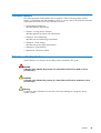
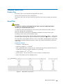
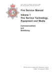
For optimum site safety and security, the following figure shows an example of recommended
Data Processing Center layout.
MEDIA
PRINTING
ROOM
OFFICE
OFFICE
STORAGE
PAPER
STORAGE
COMPUTER
ROOM
ENTRANCE
LOCK
OFFICE
OFFICE
TELECOM
ROOM
Figure 3.
AIR
CONDITIONING
ROOM
POWER
SUPPLY
ROOM
ANCILLARY
EQUIPMENT
ROOM
Recommended Data Processing Center layout
Warning:
Wall and floor carpets must not to be used in the Data Processing Center.
Note:
It is recommended to provide for the removal of packing items in the Computer Room and
ancillary premises.
2-2
Site Preparation Guide
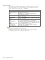
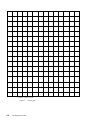
Planning Installation
Installation must be planned so that any changes and / or extensions may be implemented
with minimum service disruption. Use the layout grid shown in Figure 7 to plan installation.
Each square of the grid represents a standard raised floor panel.
CAUTION:
It is mandatory for Data Processing Center layout to take the safety of personnel into
account. Access for stretchers must be provided around the server and peripherals.
The following items must be located on the layout grid shown in Figure 7 Layout grid,
on page 2-6:
• cableways,
• extension cables,
• power and telephone sockets,
• storage cabinets.
ÉÉÉÉÉÉ
ÉÉÉÉÉÉ
ÉÉÉÉÉÉ
ÉÉÉÉÉÉ
ÉÉÉÉÉÉ
ÉÉÉÉÉÉ
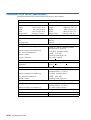
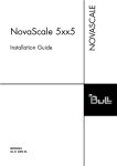
Cable Cut-outs
A cable cut-out must be provided at the front or rear base of each cabinet.
<
35 cm
(14 in)
<
15 cm
(6 in)
<
Cable cut–out
>
Server
Cable cut-out
NovaScale Blade 2xxx Servers
Rear
NovaScale 3xx5 Servers
Rear
NovaScale 40x0 Servers
Rear
NovaScale 5xx0 Servers
Front (main cabinet)
net)
NovaScale 5xx5 SMP Servers
Rear
NovaScale 6xx0 Servers
Front (main cabinet)
net)
NovaScale 5xx5 Partitioned Servers
Rear
Figure 4.
Rear (I/O cabi-
Rear (I/O cabi-
Cabinet cable cut-outs
Power Cables
One power supply cable, per PDU and/or CSS Module, must be routed by the Customer to
the cable cut-out at the base of each cabinet.
Note:
For further details, see Cabling Requirements, on page 4-2
Fitting out the Premises
2-3
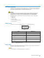
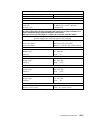
Network Cables
The following table indicates the number of Ethernet and Modem cables to be routed to the
cable cut-out at the base of each cabinet if the server is to be connected to the Customer's
LAN (for remote operation, administration, or maintenance):
Server
Network Cable
Production: 1 to 4 x 10/100/1000 Mb Ethernet cable per
NovaScale Blade 2xxx embedded Ethernet Switch.
Management: 1 x 10/100 Mb Ethernet cable per
Servers
Chassis Management Module.
NovaScale 3xx5 Servers
1 x 10/100 Mb Ethernet cable or1 Gigabit Ethernet cable
per server CPU drawer
NovaScale 40x0
Servers
1 x 10/100 Mb Ethernet cable or1 Gigabit Ethernet cable
per server CPU drawer
NovaScale 5xx0
Servers
NovaScale 6xx0
Servers
NovaScale 5xx5 SMP
Servers
NovaScale 5xx5
Partitioned Servers
1 x 10/100 Mb Ethernet cable for the integrated
Platform Administration & Maintenance computer (PAP unit)
1 x 10/100 Mb Ethernet cable or 1 Gigabit Ethernet cable
per Central Subsystem (CSS) module
1 x Modem cable equipped with an RJ11 connector
(Remote Maintenance Modem)
Note:
Modem cable connectors differ from country to country.
Customers are to provide the RJ11 adapter required to comply with national standards.
For further details, please consult your Bull Sales Representative.
2-4
Site Preparation Guide
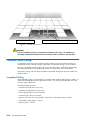
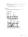
Service Clearance
It is mandatory to comply with the service clearance requirements indicated in the following
figures:
Rear door
100 cm
(39.4 in)
Server
Cabinet
Depth *
Server/ Wall
100 cm
(39.4 in)
Width *
Server/ Wall
100 cm
(39.4 in)
150 cm
(59 in)
Figure 5.
Single cabinet service clearance
Rear doors
100 cm
(39.4 in)
Main
Cabinet
Depth *
Server/ Wall
100 cm
(39.4 in)
Width *
Extension
Cabinet
Width *
Server/ Wall
100 cm
(39.4 in)
150 cm
(59 in)
Figure 6.
Dual cabinet service clearance
* Depth (110 to 130 cm), Width (60 to 65 cm)
Warning:
Full access to the cabinet is mandatory for maintenance.
Customers are advised to plan ahead and to provide space for extensions.
Fitting out the Premises
2-5
1 square = 60 x 60 cm
Figure 7.
2-6
Site Preparation Guide
Layout grid
Electrical / Electromagnetic Interference
Generators of electromagnetic interference may adversely affect server operation. The
following sources of electrical and / or electromagnetic interference must not be located in
the immediate vicinity of the Data Processing Center:
• high-voltage lines,
• radars,
• radios or other transmitters.
The server must not be subjected to electric / magnetic fields in excess of:
• electric field (E): 3 V/m,
• magnetic field (H): 30 A/m.
Warning:
The installation of an "on-line" Uninterruptible Power Supply (UPS) is strongly recommended
to ensure continuity of service and to protect the system in the event of a mains failure.
The UPS may be installed in the Computer Room or in an ancillary room.
Fire Protection
For effective fire protection, the fire detection and extinction system must be specially
designed for the Data Processing Center, which must be located in a fire area surrounded by
fire-protection walls, partitions and doors.
Fire Detection
The Customer must ensure that the following areas are monitored:
• the raised floor plenum,
• the Computer Room environment,
• the suspended ceiling plenum (where applicable),
• adjacent and ancillary rooms.
Ionic, optic, thermovelokinetic type detectors are generally used for fire detection.
The detection circuit must comprise at least two independent loops, each of which must be
equipped with different detectors.
Extinguishing Procedure
The extinguishing procedure must delay the emission of the extinguishing agent in order to:
• warn (visual and audio signals) and evacuate personnel,
• give a visual alarm outside the premises as to the presence of extinguishing gases,
• cut off power (hardware, lighting, air conditioning) - except emergency lighting units.
It is recommended to install portable extinguishers in the Computer Room and ancillary
rooms ("water sprays" in the vicinity of paper systems and storage) for use in the event of
small, contained fires.
Note:
If the server is installed in a room equipped with water sprinklers, water pipes must only be
loaded subsequent to a primary detection.
Fitting out the Premises
2-7
Extinguishing Agents
In compliance with APSAD R13.
Commonly used extinguishing agents are:
• inert gases such as ARGONITE (Argon-based) and INERGEN,
• water in the form of sprinklers or sprays (pending certification).
CAUTION:
It is strongly recommended not to use CO gas (hazard to personnel and to equipment). The
use of HALON 1301 gas is prohibited as from January 1 2003.
Alarms
A round-the-clock alarm transfer system is recommended via:
• a watchroom,
• a dedicated in-house fire department,
• a remote monitoring center.
Water Damage
It is recommended to install detection leads, connected to alarm or remote surveillance
centers, under equipment or in high-risk zones.
Water damage in a data processing site is generally due to:
• extinguishing fires with water sprays,
• leaks in the air-conditioning system,
• leaks in water-pipes passing through the Computer Room,
• water rise following heavy rain.
2-8
Site Preparation Guide
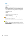
Computer Room Floor
Primary Floor
The primary floor must be sloped and equipped with a drain.
Primary floor resistance must be > 600 daN/m .
The primary floor and wall risers located at raised floor level must be coated with dustproof
paint.
Raised Floor
CAUTION:
A raised floor compliant with Standard NF P67 103-1 and 103-2, dated April 1993 is
mandatory for the Bull NovaScale Servers.
A raised floor allows even distribution of the overall system load and provides a plenum
space for cabling and air-conditioning.
The structure must be reinforced by intermediate crossbeams or T-beam section spars,
according to slab cutouts and the hardware load.
The raised floor structure (at the actuator base) must be meshed with > 20mm section, flat,
tin-plated copper braiding. See Figure 15 Raised floor equipotentiality method, on page 4-6.
The raised floor must be made of 60 cm x 60 cm, removable, interchangeable, square slabs
supported by adjustable flat-head actuators (18 per silo), fitted with electrically conductive
rubber pads.
Raised Floor Features:
• resistance: > 500 daN/m2,
• temporary resistance: > 2.5 kN/m2,
• slabs: galvanized steel or aluminium trays, inside which high density particle boards are
bonded and covered with plastic laminate or vinyl flooring,
• volume resistivity: 104 - 1010 ohms,
• plenum space: > 30 cm to allow the correct circulation of conditioned air,
• slab surface flatness must be checked by laser.
Figure 8.
Raised floor cross-section
Fitting out the Premises
2-9
Actuators alone
Figure 9.
Actuators and T–beam section spars
Raised floor structure
CAUTION:
If the air-conditioning unit(s) is (are) placed on brackets in the room, it is mandatory to
electrically isolate these brackets from the raised floor slabs, crossbeams, and actuators.
Computer Room Ceiling
It is extremely important to have sufficient ceiling height so that the premises may be airconditioned without creating draughts. Optionally, a suspended ceiling may be installed.
Ceiling or suspended ceiling height must be at least 2.50 meters. Insufficient ceiling height
may adversely affect the air-conditioning system and make personnel uncomfortable.
The primary ceiling and wall drops located at suspended ceiling level must be coated with
dustproof paint.
Suspended Ceiling
The suspended ceiling must be made of a non-pulverulent material (metal slabs or plates). To
avoid slab disintegration and the generation of dust, it is strongly recommended not to use
"mineral" type components.
Suspended Ceiling Features:
• reduces the sound level in the room,
• improves the appearance of the room,
• allows light fittings to be flush-mounted,
• conceals pipes, ducts or channels,
• glass or rock wool can only be used if contained in a dust-proof bag or cushion,
• suspended ceiling height: > 2.50 m,
• plenum space: > 20 cm.
2-10
Site Preparation Guide
Sound-Proofing
The sound level in the Computer Room may be relatively high due to room structure,
air-conditioning and hardware ventilation systems.
The most effective means of attenuating noise are to:
• use dedicated rooms (Printing Room, Console Room, etc.),
• install a suspended ceiling,
• sound-proof walls and partitions.
Protection from Sunlight
Large glass surfaces must be protected from sunlight. In no event may the Bull NovaScale
Server be exposed to direct sunlight.
External protections only may be used (coating, canvas curtains or shutter blinds).
Note:
Venetian blinds may not be used inside the Computer Room.
Cleaning
Dust has an adverse effect on the correct operation of data processing systems and their
environment. Floors must be cleaned every day with a damp floor-cloth.
Notes:
It is mandatory not to use polish and wax on floors as they may remove the anti-static
qualities of the floor covering (raised floor slabs). Once a year, specialists must be called in
to clean the raised floor, the suspended ceiling, and their plenums.
The Computer Room must comply with standard NF X44-101, dated May 1999
"Classification of contamination by solid particles", Class 4 000 000.
Fitting out the Premises
2-11
Media Storage Room
Media may be stored in the Computer Room or in an adjacent room, in which case
Computer Room environmental conditions are applicable.
The Media Storage Room floor must be designed to support loads of up to 10 kN/m .
Media is sensitive to high-power electromagnetic fields. Media must not be stored in the
vicinity of electric ducts, lightning rod chutes, transformers, etc.
Paper Storage Room
The Paper Storage Room floor must be designed to support loads of up to 10 kN/m .
Paper must be stored in a dry room with easy access to the Computer Room. It is not
mandatory to air-condition the Paper Storage Room. However, hygrometry must be
maintained at between 40 and 60 %.
Note:
Paper reams must be removed from their pallets prior to transfer to the Computer Room.
Printing Room
It is strongly recommended to install all printers, including non-impact printers (laser,
magnetographic printers, etc.), in a dedicated room with its own air-conditioning system.
A large volume of rapid printing generates more paper dust than a standard printer. Should
it be impossible to install printers in a separate environment, the following conditions must be
complied with in order to maintain maximum configuration availability:
• printers must be placed in the air flow, as far away as possible from disks and magnetic
tapes,
• full account must be taken of the significant heat dissipation of this type of hardware,
• the room must be cleaned frequently:
-
the floor must be cleaned daily.
-
the raised floor plenum must be cleaned approximately every six months.
Ancillary Equipment Room
Machining devices such as decollators and shredders generate dust and must not be installed
in the Computer Room.
These devices must be powered from the same power network as the other ancillary
equipment on the site. They must not be connected to the dedicated "data processing system"
power supply.
2-12
Site Preparation Guide
Chapter 3. Air-Conditioning
This chapter explains air-conditioning requirements for the servers.
It includes the following topics:
• Air-Conditioning System Features and Functions, on page 3-1
• Air-Conditioning System Specifications, on page 3-2
• Checks and Alarms, see page 3-5
CAUTION:
An air-conditioning system, compliant with the requirements of NF X44-101,
Class 4 000 000, dated June 1981 and with ISO 7730, is mandatory for the Bull NovaScale
Server.
Air-Conditioning System Features and Functions
Features
The Customer's air-conditioning specialist must select a fully automatic air-conditioning system
specially designed for the Data Processing Center. Radiators, fitted with thermostatic valves,
are acceptable in certain ancillary premises only.
The air-conditioning system must comprise at least two redundant assemblies, each providing
at least 66% of the total cooling power, to ensure continuity of operation.
Note:
The air-conditioning system will dry conditioned air. It is therefore mandatory for the
air-conditioning system to include a steam generation humidifier.
Functions
Temperature Control
Changes in temperature, in particular sudden changes in temperature, accelerate the ageing
of components. It is therefore important for ambient temperature to be stable and to be
maintained within the limits required for the system.
Hygrometry Control
A low level of hygrometry induces static electricity and a high level of hygrometry induces
corrosion and mildew. It is therefore important to comply with hygrometry specifications.
Heat Dissipation
When assessing heat dissipation / balance (in kW), the Customer's air-conditioning
specialist must take the following elements into account:
• servers and extensions,
• sunlight,
• radiation from outside walls,
• transmission of heat through walls separating the Computer Room from adjacent rooms,
• lighting,
• personnel,
• air renewal.
Air Conditioning
3-1
Air-Conditioning System Specifications
Warning:
If the air-conditioning system is shut down, "operational" conditions must be re-established, in
compliance with temperature and hygrometry gradients, AT LEAST ONE HOUR before
powering up the server.
To optimize the air duct network, air-conditioning cabinet(s) must be installed in the Computer
Room or in an adjacent room. Filters must be easily accessible for regular checks and easy
cleaning.
All materials liable to fragment, disintegrate, or crumble through ageing, handling or when
subjected to conditioned air flows are prohibited. If the use of such materials cannot be
avoided, they must be coated with anti-rust paint. Ventilation ducts must be made of a
non-combustible, non-pulverulent material. Glass or mineral fibers must not be used in the
conditioned air distribution or recycling circuit, unless packed in seal-tight bags.
The effectiveness of air-conditioning unit filters must comply with the "A.S.H.R.A.E" test, >
36% (to be checked with manufacturers).
Air Renewal, Distribution, Circulation, Pollution, and Filtering
Renewal
A fresh air supply is mandatory for the comfort and health of personnel. The fresh air supply
must be directly input at air-conditioning unit level and must be filtered in compliance with
local health authority regulations (D.D.A.S.S. Regulations in France).
The Data Processing Center is over-pressurized via the fresh air supply which must be strictly
limited to 1 - 1.5 times room air per hour. Over-pressurization presents the advantage of
moving air outwards, thereby preventing dust from entering the premises.
Distribution
Bull NovaScale Servers release high levels of heat and require the installation of a high
airflow air-conditioning system.
Delivery of air through the raised floor plenum is the most appropriate solution. The
air-conditioning specialist must define the number and location of the perforated and / or
damper slabs required for correct air distribution.
Advantages:
• absence of constant draughts,
• airflow directed from the bottom up, from cold to hot,
• good air distribution through perforated or damper slabs,
• easy layout changes.
Note:
It is mandatory not to install hardware or furniture on one or more perforated / damper
slabs in the Computer Room.
3-2
Site Preparation Guide
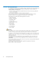
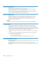
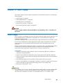
Circulation
The servers are cooled by taking air from inside the room. The following requirements are to
be complied with for correct air circulation of air:
• raised floor height: > 30 cm,
• the raised floor plenum must not be obstructed by oversize pipes or cableways,
• raised floor slabs must be correctly fitted.
Warning:
Do not place perforated / damper slabs in the immediate vicinity of one or more
air-conditioning cabinets, as shown in the following figure.
Air conditioning unit
Air
130 mm
H
Deflector if < 350 mmTubes to draught
ÌÌÌÌÌÌÌÌÌÌÌÌÌÌÌÌÌÌÌ
ÌÌÌÌÌÌÌÌÌÌÌÌÌÌÌÌÌÌÌ
ÌÌÌÌÌÌÌÌÌÌÌÌÌÌÌÌÌÌÌ
ÏÏÏ
ÏÏÏÏÏÏ
ÏÏÏÏÏ
ÏÏÏ
ÌÌÌÌÌÌÌÌÌÌÌÌÌÌÌÌÌÌÌ
ÏÏÏ
ÏÏÏÏÏÏ
ÏÏÏÏÏ
ÏÏÏ
ÎÎ
ÎÎ
ÎÎ
ÌÌÌÌÌÌÌÌÌÌÌÌÌÌÌÌÌÌÌ
ÏÏÏ
ÏÏÏÏÏÏ
ÏÏÏÏÏ
ÏÏÏ
ÎÎ
ÎÎ
ÎÎ
ÌÌÌÌÌÌÌÌÌÌÌÌÌÌÌÌÌÌÌ
ÏÏÏ
ÏÏÏÏÏÏ
ÏÏÏÏÏ
ÏÏÏ
ÎÎ
ÎÎ
ÎÎ
ÏÏ
ÏÏ
ÏÏ
ÌÌÌÌÌÌÌÌÌÌÌÌÌÌÌÌÌÌÌ
ÎÎ
ÎÎ
ÎÎ
ÏÏ
ÏÏ
ÏÏ
ÌÌÌÌÌÌÌÌÌÌÌÌÌÌÌÌÌÌÌ
ÎÎ
ÎÎ
ÎÎ
ÏÏ
ÏÏ
ÏÏ
ÌÌÌÌÌÌÌÌÌÌÌÌÌÌÌÌÌÌÌ
ÎÎ
ÎÎ
ÎÎ
ÏÏ
ÏÏ
ÏÏ
ÌÌÌÌÌÌÌÌÌÌÌÌÌÌÌÌÌÌÌ
ÌÌÌÌÌÌÌÌÌÌÌÌÌÌÌÌÌÌÌ
ÌÌÌÌÌÌÌÌÌÌÌÌÌÌÌÌÌÌÌ
ÌÌÌÌÌÌÌÌÌÌÌÌÌÌÌÌÌÌÌ
Figure 10. Example of poor air distribution
A ir Le aks
C ables
P iping
H
Figure 11. Example of obstacles that may obstruct air circulation
Air Conditioning
3-3
Pollutants
There are three types of pollutants:
• liquids,
• solid particles,
• gases.
Damage varies according to pollutant type and interaction: corrosion, erosion, mildew,
oxidation, etc.
Solid particles are abrasive, electrostatic, and absorbent. They generally originate from:
• surface crumbling of construction materials used to fit out the Data Processing Center,
• the formation of rust inside air conditioning units and on raised floor supports,
• systems (e.g. printers, ...),
• insufficient filtering of fresh air,
• personnel.
Polluted air results in:
• clogged filters and impaired thermal dissipation,
• damaged connections (contact points) = intermittent failures,
• deterioration of magnetic media,
• premature wear and tear of components and moving parts.
Note:
The Computer Room and ancillary premises must be cleaned thoroughly at frequent intervals.
See Cleaning on page 2-11 for further details.
Gas pollution is difficult to control.The known effects of gas pollution on equipment and
hardware are corrosion and oxidation.
CAUTION:
In a standard data processing environment, gas concentration does not exceed an acceptable
level. However, if there are chemical or industrial processing factories in the vicinity, if
chemical odors are present, or if any other symptom or inherent problem is detected, the site
must be analyzed immediately.
3-4
Site Preparation Guide
Checks and Alarms
The air-conditioning system is controlled automatically. Variations outside the specified
temperature and hygrometry ranges must be transmitted to Customer Service Engineers.
Detectors must be installed at the air-conditioning cabinet air inlet and / or in the Computer
Room. Alarms must indicate any variation outside the specified Computer Room climatic
environment conditions.
A weekly thermo-hygrograph recording sheet must be displayed so that any disruptions in the
air-conditioning system can be viewed and recorded. Thermo-hygrograph recording sheets
must be archived for at least three months.
Warning:
Do not install detectors on panels that are subject to climatic variations (e.g. outside walls,
...).
In order to avoid damage to or the destruction of electronic equipment, a dynamic safety
device must automatically cut off the electric power supply to the system if ambient
temperature exceeds 27° / 30° C.
Air Conditioning
3-5
3-6
Site Preparation Guide
Chapter 4. Power Supply
This chapter explains power supply requirements for Bull NovaScale Servers. It includes the
following topics:
• Power Supply, on page 4-1
• Cabling Requirements, on page 4-2
• Grounding Circuit, on page 4-5
• Neutral Power System, on page 4-6
• Non-Computing Power Supply, on page 4-8
DANGER
A power supply compliant with Standard NFC 15.100, dated May 1991, is mandatory for
the servers.
Power Supply
Inrush current on connecting the server to the main AC power supply may be significant. The
Bull NovaScale Server CSS module is equipped with a switch-mode power supply that
absorbs sinusoidal currents.
Each PDU is equipped with a switch-mode power supply that absorbs non-sinusoidal currents.
To ensure that interferences or faults generated by other systems and devices do not affect
server operation, the CSS module and the PDU/UPS must be powered through an AC
protection.
Electric and data cables must be laid in bulk on the primary slab, in the raised floor plenum.
If cableways are required, electricity distribution cables must be separated from data
transmission cables (separation of high and low currents) by at least 30 cm.
Prerequisites:
• Provision of the power supply interface and the corresponding electrical installation in
compliance with specifications.
• Provision and installation of the electric power supply panel (and required protections).
• Provision of power supply cables from the electricity distribution panel up to the hardware
connection point.
• Grounded plug sockets for the connection of the system to the power supply.
• Provision and installation of an emergency shutdown system (lock system) and of a power
supply cut-off device at general Data Processing Center circuit breaker level.
• Power factor requirement: > 90%.
Warning:
The installation of an "on-line" Uninterruptible Power Supply (UPS) is strongly recommended
to ensure continuity of service and to protect the system in the event of a mains failure.
The UPS may be installed in the rack, in the Computer Room or in an ancillary room.
Power Supply
4-1
DANGER
• To ensure the protection of personnel and equipment, bipolar magneto-thermic circuit
breakers must be installed on the phase and neutral wires, in compliance with the safety
standards in force.
• Power must be exclusively conveyed by copper conductors from the source. Aluminium
conductors are prohibited. It is mandatory to separate the power supply for the server
from the non-computing power supply.
Cabling Requirements
The Customer is responsible for providing the dedicated power supply to the base of the
cabinet. As equipment in Data Processing Centers is moved frequently, standards require the
use of flexible power cables.
One power supply cable, per PDU/UPS and/or CSS Module, must be routed by the
Customer to the cable cut-out at the base of each cabinet, or for UPS 7.5 KVA & 10 KVA,
into hard wire receptacle in the side.
Important:
Each Power Distribution Unit (PDU) and the UPS require an extra cable length of 1.5 meters
for connection inside the cabinet.
The Central Subsystem (CSS) Module cable length allows connection in the plenum space at
the base of the cabinet.
Note:
See Appendix A for details.
CAUTION:
It is mandatory for power lines and terminal boxes to be located within the immediate
vicinity of the system and to be easily accessible.
Each power line must be connected to a separate, independent electrical panel and bipolar
circuit breaker.
France:
Power sockets and plugs must be compliant with Decree 88-1056 Article 20-IV, dated 14th
November 1988.
Warning:
Cables must be correctly labeled at both ends with the following information:
• the device to which each cable end is being connected,
• the physical location of the other end of the cable (ID: building, floor, column, ...),
• the length of the cable run.
The Customer is responsible for ensuring that the AC electricity supply is compliant with
national and local recommendations, regulations, standards, and codes of practice.
4-2
Site Preparation Guide
Mounting Power Supply Cable Sockets
CAUTION:
To be performed by a certified electrician only.
Tools Required
• Multimeter
• Phillips screwdriver
• Velcro fasteners
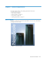
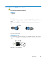
Europe, Brazil
PDU/UPS power cables are equipped with ready-mounted IEC60309 plugs. The Customer is
responsible for supplying and installing appropriate sockets for connection to the site power
supply.
Except for UPS 7.5 & 10 KVA: Power Cables are hard wired directly in the UPS without
plug.
Figure 12. Plug and socket
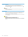
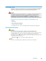
United States of America
Server power cables are equipped with ready-mounted NEMA L6-30P plugs. The Customer is
responsible for supplying and installing appropriate sockets for connection to the site power
supply.
Figure 13. US plug characteristics
Power Supply
4-3
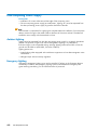
For PDU/UPS equipped with IEC 60309 plugs.
1. Check that the power supply cable is not live with the multimeter.
2. Carefully guide the power supply cable through the cable inlet at the base of the cabinet.
3. Check that the power supply cable is long enough.
4. Unscrew the base of the socket (A), insert the cable through the socket base (B), and wire
to the socket head, as shown in Figure 14.
Figure 14. PDU/UPS Power socket
5. Screw the socket base back to the socket head (C).
6. Check for < 0.1 ohm resistance between the grounding pin on the power cable plug and
the metal frame with the multimeter.
7. Connect the power supply cable socket to the power cable plug.
8. Use velcro fasteners to secure the cable into place along the cabinet frame.
4-4
Site Preparation Guide
Grounding Circuit
The electronic components inside the servers are sensitive to high-frequency electromagnetic
interference. To ensure correct hardware operation, high-frequency interference must be
limited via an equipotential ground circuit and metallic braid shielded cables.
DANGER
For the protection of personnel and hardware, it is mandatory for the grounding network to
be compliant with Data Processing Center requirements and the standards in force.
A single, equipotential grounding circuit dedicated to data processing systems is required. If
the building has several, separate grounding shafts, it is mandatory for them to be
interconnected to eliminate the occurrence different transient potentials within the same unit.
Electric protection wire characteristics (in compliance with Standard NFC 15.100):
• flexible,
• multi-strand,
• black, noise-free grounding wire,
• insulated along its entire length,
• cross-section: 25 mm - 95 mm according to Data Processing Center configuration.
Grounding the Raised Floor
CAUTION:
The raised floor must be grounded in compliance with Standard EN 50174-2.
An equipotentiality mesh must be laid under the raised floor structure. Raised floor actuators
must be grounded with > 10 mm x 2 mm flat, tin-plated braiding connected to the
equipotentiality strap in the dedicated Data Processing Center electricity distribution cabinet.
• Raised floor slab: 60 cm x 60 cm.
• Meshing braid: > 10 mm cross-section tin-plated copper braid.
Note:
At each strut, the meshing braid is attached to the actuator via a metal collar.
Power Supply
4-5
Figure 15. Raised floor equipotentiality method
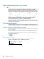
Neutral Power System
A TN-S neutral point connection system is mandatory for the servers.
Constructing a TN-S Neutral Point Connection System
The servers are equipped with a high-leakage current switch-mode power supply.
The protective conductor (PE) is connected to the neutral conductor at the origin of the
installation. As the Neutral and the PE wire are connected to the same output point of the
source, the voltage measured between "Neutral" and "Ground" at any point in the
installation must approach 0 Volt.
At the secondary winding of the power supply interface, the Neutral point is directly
connected to the grounding shaft measurement strip, or to the nearest outlet. This connection
is called the "Neutral reference wire".
DANGER
When defining a neutral point connection, the output Neutral point of a power source or
power supply interface must always be directly connected (referenced) to the nearest
grounding shaft strip and never to a grounding point.
4-6
Site Preparation Guide
Power Supply
Interface
N
N
Electricity
Distribution
Panel
P.E
Data processing equipotential line =
flexible multi-strand wire in compliance
with standard NFC 15.100.
Data processing
equipotential bar
Raised floor actuator
meshing braid
Computer and peripherals
cab.
cab.
P.E
Y/G
Main earth
plate terminal
Measurement bar
Figure 16. Grounding circuit diagram for a TN-S neutral point connection
Power Supply
4-7
Non-Computing Power Supply
Prerequisites
• Installation of current outlets around the edge of the computing room.
• The non-computing power supply (air-conditioners, lighting, etc.) must be separated from
the data processing power supply by specific distribution cabinets.
Note:
The Customer is responsible for supplying the complete electrical installation, from the power
delivery station through to the cable outlets at the base of the server cabinet. The electrical
installation must comply with the standards in force.
Ambient Lighting
Lighting must be separated from the data processing power supply by a specific distribution
cabinet. The position of lights must ensure homogeneous lighting. It is preferable to
flush-mount lights in the suspended ceiling. Average lighting measured at 0.85 m from the
ground must be 500 Lux (ISO 8995, future EN 12464-1).
Lighting options are:
• Instant-lighting tubes equipped with interference suppressors to limit electromagnetic wave
interference.
• Halogen lamps without intensity regulators.
Emergency Lighting
Autonomous emergency lighting units must be installed. If lighting in the Computer Room is
accidentally turned off, the emergency lighting system must indicate the Emergency EXIT
(green marking mandatory), for the safe evacuation of personnel.
4-8
Site Preparation Guide
Appendix A. Specifications
• NovaScale 20xx cabinet specifications, on page A-2
• NovaScale 20xx chassis specifications, on page A-4
• NovaScale 2020 server specifications, on page A-5
• NovaScale 2021 server specifications, on page A-5
• NovaScale 2040 server specifications, on page A-5
• NovaScale 2320 server specifications, on page A-6
• NovaScale 3005 series sever cabinet specifications, on page A-7
• NovaScale 3025 server CPU drawer specifications, on page A-9
• NovaScale 3045 server CPU drawer specifications, on page A-10
• NovaScale 3045 COMPACT server CPU drawer specifications, on page A-11
• NovaScale 4020/4040 server specifications, on page A-12
• NovaScale 5080/5160.6080/6160 server specifications, on page A-16
• NovaScale 5320/6320 server specifications, on page A-18
• NovaScale 5085 server specifications, on page A-20
• NovaScale 5165 server specifications, on page A-22
• NovaScale 5245 Server Specifications, on page A-24
• NovaScale 5325 Server Specifications, on page A-26
• UPS References, on page A-28
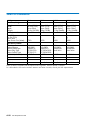
Specifications and Features
A-1
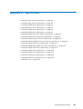
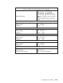
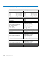
NovaScale Blade 2xxx Cabinet Specifications
NovaScale Blade chassis are delivered rack-mounted in a 19U or 40U cabinet.
Cabinet Dimensions / Weight
Unpacked
Packed
1100H
Height:
Width:
Depth:
Weight (empty):
Weight (max):
1100H
195.5 cm (77.0 in)
60.0 cm (23.6 in)
111.5 cm (43.9 in)
205 kg (452 lbs)
600 kg (1330 lbs)
1100L
Height:
Width:
Depth:
Weight (empty):
Weight (max):
Height:
Width:
Depth:
Weight (empty):
Weight (max):
200.0 cm (78.7 in)
80.0 cm (31.5 in)
122.0 cm (48.0 in)
235 kg (364 lb)
630 kg (2128 lb)
1100L
103.5 cm (40.7 in)
60.0 cm (23.6 in)
111.5 cm (43.9 in)
143Kg (315 lbs)
400Kg (880 lbs)
Height:
Width:
Depth:
Weight (empty):
Weight (max):
108.0 cm (42.5 in)
80.0 cm (31.5 in)
122.0 cm (48.0 in)
173 kg (382 lb)
430 kg (947 lb)
Service Clearance
Front
Rear
Side (left and right)
150 cm (60 in)
100 cm (40 in)
100 cm (40 in)
Power cables
PDU-2-4-M-32A (1100H/L cabinets)
AC (32A)
Cable type
Connector type
1 per PDU
3 x AWG10 ( 3 x 6 mm2 / #10US)
IEC60309-32A
PDU-0-7-M-32A (1100H/L cabinets)
AC (32A)
Cable type
Connector type
1 per PDU
3 x AWG10 ( 3 x 6 mm2 / #10US)
IEC60309-32A
PDU-4-2-M-63A (1100H/L cabinets)
AC (63A)
Cable type
Connector type
1 per PDU
3 x AWG06 ( 3 x 16 mm2 / #06US)
IEC60309-63A
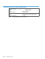
It is mandatory for power lines and terminal boxes to be located within the immediate vicinity of the system and to be easily accessible. Each power line must be connected to a separate, independent electrical panel and bipolar circuit breaker. PDUs require an extra
cable length of 1.5 meters for connection inside the cabinet.
PDU-4-2-M-63A:
Power sockets and plugs must be compliant with Decree 88-1056 Article 20-IV, dated 14th
November 1988.
A-2
Site Preparation Guide
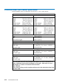
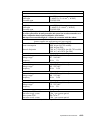
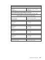
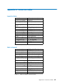
Electrical Specifications
(power supplies are auto-sensing and auto-ranging)
Power consumption
5000 VA (max. per chassis)
Thermal dissipation
4706 W / 16067 BTU (max. per chassis)
Europe
Nominal voltage
Voltage range
Frequency
230 VAC (Phase / Neutral)
207 - 244 VAC
50 Hz
1%
United States of America
Nominal voltage
Voltage range
Frequency
208 VAC (Phase / Neutral)
182 - 229 VAC
60 Hz
0,3%
Japan
Nominal voltage
Voltage range
Frequency
200 VAC (Phase / Neutral)
188 - 212 VAC
60 Hz
0,2%
Brazil
Nominal voltage
Voltage range
Frequency
220 VAC (Phase / Neutral)
212 - 231 VAC
60 Hz
2%
Breaker Protection (Mains Power)
PDU-2-4-M-32A
PDU-0-7-M-32A
PDU-4-2-M-63A
Maximum inrush current
Table 1.
32A Curve C
32A Curve C
63A Curve C
210A / per quarter period
NovaScale Blade 20xx cabinet specifications
Specifications and Features
A-3
NovaScale Blade 20xx Chassis Specifications
Dimensions / Weight
Height
30.42 cm (23.25 in, 7U)
Width
44.4 cm (17.5 in)
Depth
71.1 cm (28.0 in)
Weight
Chassis + modules + Blades: 108.86 kg (240 lbs) maximum
Chassis + modules:
44.91 kg (99 lbs) maximum
Electrical
Voltage range (VAC)
Frequency
200 VAC to 240 VAC
50 to 60 Hz
5% single phase
Thermal output
- Minimum configuration:
- Maximum configuration:
428 Watts (1461 Btu/hr)
4x2000 Watt redundant power supplies
4706 Watts (16067 Btu/hr)
Temperature Requirements
Operating Limit Non-Operating
Dry Bulb Temperature
10 to 35 C
(50 to 95 F)
Humidity Requirements
Operating Limit Non-Operating
-40 to 60 C
(-40 to 140 F)
(noncondensing)
Gradient
Max. Wet Bulb Temperature
Moisture Content
8 to 80%
Not stated
Not stated
Not stated
8 to 80%
Not stated
Not stated
Not stated
Noise Emissions
System Running System Idle
Sound Power
(without acoustics module option)
Sound Power
(with acoustics module option)
7.4 bels maximum
7.4 bels maximum
6.9 bels maximum
6.9 bels maximum
Optimum Operational Reliability
Ambient Temperature
Hygrometry
Table 2.
A-4
22 C+3 C/-3 C (72 F+5 F/-5 F)
50% + 10%/-10%
NovaScale Blade 20xx Chassis specifications
Site Preparation Guide
NovaScale Blade 2020 Server Specifications
Dimensions / Weight
Height
Width
Depth
Maximum Weight
24.5 cm (9.7 in)
2.9 cm (1.14 in)
44.6 cm (17.6 in)
5.4 kg (12 lbs)
Electrical
Power
Voltage range (VDC)
Table 3.
Redundant 12 VDC (220 W max.)
12 VDC
NovaScale Blade 2020 Server specifications
NovaScale Blade 2021 Server Specifications
Dimensions / Weight
Height
Width
Depth
Maximum Weight
24.5 cm (9.7 in)
2.9 cm (1.14 in)
44.6 cm (17.6 in)
5.4 kg (12 lbs)
Electrical
Power
Voltage range (VDC)
Table 4.
Redundant 12 VDC (300W max.)
12 VDC
NovaScale Blade 2021 Server specifications
NovaScale Blade 2040 Server Specifications
Dimensions / Weight
Height
Width
Depth
Maximum Weight
24.5 cm (9.7 in)
5.9 cm (2.32 in)
44.6 cm (17.6 in)
7.5 kg (16.5 lbs)
Electrical
Power
Voltage range (VDC)
Table 5.
Dual redundant 12 VDC (400 W max.)
12 VDC
NovaScale Blade 2040 Server specifications
Specifications and Features
A-5
NovaScale Blade 2320 Server Specifications
Dimensions / Weight
Height
Width
Depth
Maximum Weight
24.5 cm (9.7 in)
2.9 cm (1.14 in)
44.6 cm (17.6 in)
5.4 kg (12 lbs)
Electrical
Power
Voltage range (VDC)
Table 6.
A-6
Dual redundant 12 VDC (400 W max.)
12 VDC
NovaScale Blade 2320 Server specifications
Site Preparation Guide
NovaScale 3005 Series Server Cabinet Specifications
The Novascale 3005 Series are delivered rack-mounted in a 19U or 40U cabinet.
40U Cabinet Dimensions / Weight
Height:
Width:
Depth:
Weight (empty):
Weight (full):
Unpacked
195.0 cm (77.0 in)
65.0 cm (25.6 in)
113.6 cm (44.7 in)
225 kg (496 lb)
680 kg (1280 lb)
Height:
Width:
Depth:
Weight (empty):
Weight (full):
Packed
200.5 (80.7 in)
80.0 cm (31.5 in)
120.0 cm (47.2 in)
255 kg (562 lb)
610 kg (1345 lb)
19U Cabinet Dimensions / Weight
Height:
Width:
Depth:
Weight (empty):
Weight (full):
Unpacked
100.0 cm (39.4 in)
65.0 cm ( 25.6 in)
113.6 cm (44.7 in)
200 kg (440 lb)
390 kg (860 lb)
Front
Rear
Side (left and right)
Height:
Width:
Depth:
Weight (empty):
Weight (full):
Packed
118.0 cm (46.49 in)
80.0 cm ( 31.5 in)
120.0 cm (47.2 in)
230 kg (507 lb)
420 kg (927 lb)
Service Clearance
150 cm
100 cm
100 cm
Power Cables
AC (20A)
1 per PDU
Cable type
3 x 4 mm2 / AWG # 12 (US)
Connector type
C22 Appliance Coupler
It is mandatory for power lines and terminal boxes to be located within the immediate
vicinity of the system and to be easily accessible. Each power line must be connected to
a separate, independent electrical panel and bipolar circuit breaker.
The PDU requires an extra cable length of 1.5 meters for connection inside the cabinet
Specifications and Features
A-7
Electrical specifications
(power supplies are auto-sensing and auto-ranging)
Current draw
24 A max. at 240 VAC input per PDU
Power consumption
8800 VA (max. 40U cabinet)
5500 VA (max. 19U cabinet)
5700 VA (max. per PDU)
Thermal dissipation
1500 VA / 5100 BTU (per Novascale 3045 CPU drawer)
Nominal voltage
Voltage range
Frequency
Nominal voltage
Voltage range
Frequency
Nominal voltage
Voltage range
Frequency
Nominal voltage
Voltage range
Frequency
Mains power PDU
Maximum inrush current
Table 7.
A-8
Europe
230 VAC (Phase / Neutral)
207 - 244 VAC
50 Hz ±1%
United States of America
208 VAC (Phase / Neutral)
182 - 229 VAC
60 Hz ±0.3%
Japan
200 VAC (Phase / Neutral)
188 - 212 VAC
60 Hz ±0.2%
Brazil
220 VAC (Phase / Neutral)
212 - 231 VAC
60 Hz ±2%
Breaker Protection
20A Curve C
210A/per quarter period
NovaScale 3005 Series Server Cabinet Specifications
Site Preparation Guide
Novascale 3025 Server CPU Drawer Specifications
Height:
Width:
Depth:
Weight (base model)
Weight (max)
Power
Voltage range (VAC)
Frequency
Current
Thermal output (typical)
Dimensions/Weight
17.6 cm (6.9 inches, 4U)
44.1 cm (17.3 inches)
76.5 cm (30.1 inches)
21 kg (46.3 lbs)
48 kg (105.8 lbs)
Electrical
1760VA
200 VAC to 240 nominal, autoranging (+6% -10%)
50 to 60 Hz ± 5%
6.4 amps
1090 VA
Temperature Requirements
Dry Bulb Temperature
Gradient
Operating
5 to 35 °C
(41 to 95° F)
Not stated
Non-operating
-10 to +43°C
(14 to 109.4°F)
Not stated
Humidity Requirements
(non condensing)
Gradient
Max. wet Bulb temperature
Moisture Content
Operating
20 to 80%
Not stated
Not stated
Not stated
Non-operating
< 95 % at 25 to 35°C
Not stated
Not stated
Not stated
Noise emissions
Acoustic test at room temperature of 28°C (82°F) without failure condition
Operating
Non-operating
Sound Power (Dome method)
7.0 BA
Not stated
Sound pressure (Bystander, floor60 dBA
N/A
standing)
Table 8.
NovaScale 3025 Server CPU drawer specifications
Specifications and Features
A-9
NovaScale 3045 Server CPU Drawer Specifications
Height:
Width:
Depth:
Weight (base model)
Weight (max)
Power
Voltage range (VAC)
Frequency
Current
Thermal output (typical)
Dimensions/Weight
17.6 cm (6.9 inches, 4U)
44.1 cm (17.3 inches)
76.5 cm (30.1 inches)
21 kg (46.3 lbs)
48 kg (105.8 lbs)
Electrical
1760VA
200 VAC to 240 nominal, autoranging (+6% -10%)
50 to 60 Hz ± 5%
6.4 amps
1760 VA
Temperature Requirements
Dry Bulb Temperature
Gradient
Operating
5 to 35 °C
(41 to 95° F)
Not stated
Non-operating
-10 to +43°C
(14 to 109.4°F)
Not stated
Humidity Requirements
(non condensing)
Gradient
Max. wet Bulb temperature
Moisture Content
Operating
20 to 80%
Not stated
Not stated
Not stated
Non-operating
< 95 % at 25 to 35°C
Not stated
Not stated
Not stated
Noise emissions
Acoustic test at room temperature of 28°C (82°F) without failure condition
Operating
Non-operating
Sound Power (Dome method)
7.0 BA
Not stated
Sound pressure (Bystander, floor60 dBA
N/A
standing)
Table 9.
A-10
NovaScale 3045 Server CPU drawer specifications
Site Preparation Guide
NovaScale 3045 COMPACT Server CPU Drawer Specifications
Height:
Width:
Depth:
Weight (base model)
Weight (max)
Power
Voltage range (VAC)
Frequency
Current
Thermal output (typical)
Dimensions/Weight
8.7 cm (3.4 inches, 2U)
44.1 cm (17.3 inches)
76.5 cm (30.1 inches)
21 kg (46.3 lbs)
33 kg (72.8 lbs)
Electrical
1280VA
200 VAC to 240 nominal, autoranging (+6% -10%)
50 to 60 Hz ± 5%
6.4 amps
1280 VA
Temperature Requirements
Dry Bulb Temperature
Gradient
Operating
5 to 35 °C
(41 to 95° F)
Not stated
Non-operating
-10 to +43°C
(14 to 109.4°F)
Not stated
Humidity Requirements
(non condensing)
Gradient
Max. wet Bulb temperature
Moisture Content
Table 10.
Operating
20 to 80%
Not stated
Not stated
Not stated
Non-operating
< 95 % at 25 to 35°C
Not stated
Not stated
Not stated
NovaScale 3045 COMPACT Server CPU drawer specifications
Specifications and Features
A-11
NovaScale 4020/4040 Server Cabinet Specifications
NovaScale 4020 / 4040 servers are delivered rack-mounted in a 40U or 19U cabinet.
Cabinet Dimensions / Weight
Unpacked
Packed
1100H
Height:
Width:
Depth:
Weight (empty):
Weight (max):
1100H
195.5 cm (77.0 in)
60.0 cm (23.6 in)
111.5 cm (43.9 in)
135 kg (298 lb)
935 kg (2062 lb)
1100L
Height:
Width:
Depth:
Weight (empty):
Weight (max):
Height:
Width:
Depth:
Weight (empty):
Weight (max):
200.0 cm (78.7 in)
80.0 cm (31.5 in)
122.0 cm (48.0 in)
165 kg (364 lb)
965 kg (2128 lb)
1100L
103.5 cm (40.7 in)
60.0 cm (23.6 in)
111.5 cm (43.9 in)
91 kg (201 lb)
471 kg (1038 lb)
Height:
Width:
Depth:
Weight (empty):
Weight (max):
108.0 cm (42.5 in)
80.0 cm (31.5 in)
122.0 cm (48.0 in)
121 kg (267 lb)
501 kg (1120 lb)
Service Clearance
Front
Rear
Side (left and right)
150 cm (60 in)
100 cm (40 in)
100 cm (40 in)
Power cables
PDU-0-7-M-32A
(1100H/L & 1300H/L cabinets)
AC (32A)
Cable type
Connector type
1 per PDU
3 x AWG10 ( 3 x 6 mm2 / #10US)
IEC60309-32A
It is mandatory for power lines and terminal boxes to be located within the immediate vicinity of the system and to be easily accessible. Each power line must be connected to a separate, independent electrical panel and bipolar circuit breaker. PDUs require an extra
cable length of 1.5 meters for connection inside the cabinet.
A-12
Site Preparation Guide
Electrical Specifications
(power supplies are auto-sensing and auto-ranging)
Power consumption
Thermal dissipation
8800 VA (max. 40U cabinet)
5500 VA (max. 19 U cabinet)
5700 VA (max. per PDU-20A)
7300 VA (max. per PDU-0-7-M-32A)
1500 W/5100 BTU (per NovaScale
4040)
650 W/2300 BTU (per NovaScale
4020)
Europe
Nominal voltage
Voltage range
Frequency
230 VAC (Phase / Neutral)
207 - 244 VAC
50 Hz
1%
United States of America
Nominal voltage
Voltage range
Frequency
208 VAC (Phase / Neutral)
182 - 229 VAC
60 Hz
0,3%
Japan
Nominal voltage
Voltage range
Frequency
200 VAC (Phase / Neutral)
188 - 212 VAC
60 Hz
0,2%
Brazil
Nominal voltage
Voltage range
Frequency
220 VAC (Phase / Neutral)
212 - 231 VAC
60 Hz
2%
Breaker Protection (Mains Power)
PDU-20A
PDU-0-7-M-32A
Maximum inrush current
Table 11.
20A Curve C
32A Curve C
210A / per quarter period
NovaScale 4020/4040 Server cabinet specifications
Specifications and Features
A-13
NovaScale 4020 Server CPU Drawer Specifications
Dimensions / Weight
Height
Width
Depth
Weight
8.77 cm (3.5 in, 2U)
44.9 cm (17.7 in)
74.7 cm (29.4 in)
30 kg (65 lb)
Electrical
Power
Voltage range (VAC)
Frequency
Current
Thermal output (typical)
650 VA
200 VAC to 240 VAC nominal,
autoranging +6%, -10%
50 to 60 Hz
5%
3 amps
2300 Btu/hr
Temperature
Operating
Non-Operating
Dry Bulb Temperature
10 to 35 C
(50 to 95 F)
Not stated
-40 to 70 C
(-40 to 158 F)
Not stated
Gradient
Humidity
Operating
(non-condensing)
Not stated
Gradient
Not stated
95% RH, 25 to 30°C
(77 to 86° F)
Not stated
Non-Operating
Max. Wet Bulb Temperature
Not stated
Not stated
Moisture Content
Not stated
Not stated
Noise Emissions (1)
System Running System Idle
Sound Power
(Dome method)
Sound Pressure
6.7 BA
Not stated
55 dBA
N/A
(1) Acoustic tests at room temperature of 28° C (82° F) without failure condition.
Table 12.
A-14
NovaScale 4020 Server CPU drawer specifications
Site Preparation Guide
NovaScale 4040 Server CPU Drawer Specifications
Dimensions / Weight
Height
Width
Depth
Weight
17.53
44.45
71.12
48.08
cm (6.9 in, 4U)
cm (17.5 in)
cm (28.0 in)
kg (106 lb)
Electrical
Power
Voltage range (VAC)
Frequency
Current
Thermal output (typical)
1500 VA
200 VAC to 240 VAC nominal,
autoranging +6%, -10%
50 to 60 Hz
5%
6.4 amps
5100 Btu/hr
Temperature
Operating
Non-Operating
Dry Bulb Temperature
10 to 35 C
(50 to 95 F)
Not stated
-40 to 70 C
(-40 to 158 F)
Not stated
Gradient
Humidity
Operating
(non-condensing)
Not stated
Gradient
Not stated
95% RH, 25 to 30°C
(77 to 86° F)
Not stated
Non-Operating
Max. Wet Bulb Temperature
Not stated
Not stated
Moisture Content
Not stated
Not stated
Noise Emissions (1)
System Running System Idle
Sound Power
(Dome method)
Sound Pressure
7.0 BA
Not stated
60 dBA
N/A
(1) Acoustic tests at room temperature of 28° C (82° F) without failure condition.
Table 13.
NovaScale 4040 Server CPU drawer specifications
Specifications and Features
A-15
NovaScale 5080/5160/6080/6160 Specifications
NovaScale 5080/5160 Servers are delivered rack-mounted in 40U cabinets.
Cabinet Dimensions / Weight
Unpacked
Packed
1300H
1300H
Height:
Width:
Depth:
Weight (max.):
195.5 cm (77.0 in)
60.0 cm (23.6 in)
129.5 cm (51.0 in)
943 kg (2079 lb)
Height:
Width:
Depth:
Weight (max.):
200.0 cm (78.7 in)
80.0 cm (31.5 in)
140.0 cm (55.1 in)
973 kg (2145 lb)
Service Clearance
Front
Rear
Side (left and right)
150 cm
100 cm
100 cm
Operating Limits
Dry bulb temperature range
Relative humidity (non-condensing)
Max. wet bulb temperature
Moisture content
Pressure / Elevation
+15°C to +30°C (+59°F to +86°F)
Gradient 5°C/h (41°F/h)
35 to 60% (Gradient 5%/h)
+24°C (+75.2°F)
0.019 kg water/kg dry air
Sea level < 2500 m
Optimum Operational Reliability
+ 22°C (+ 3°C) (+ 72°F (+ 5°F)
50% (+ 5%)
Temperature
Hygrometry
Non-Operating Limits
Dry bulb temperature range
Relative humidity (non-condensing)
Max. wet bulb temperature
Moisture content
+5°C to +50°C (+41°F to +122°F)
Gradient 25°C/h (77°F/h)
5 to 95% (Gradient 30%)
+28°C (+82.4°F)
0.024 kg water/kg dry air
Shipping Limits
Dry bulb temperature range
Relative humidity (non-condensing)
-35°C to +65°C (-31°F to +149°F)
Gradient 25°C/h (77°F/h)
5 to 95%
Gradient 30%/h
Acoustic Power at Room Temperature +20° C (+68° F)
System Running
Lw(A) 6.3 Bels
A-16
Site Preparation Guide
System Idle
Lw(A) 6.1 Bels
Power Cables
PDU-0-7-M-32A
AC (32A)
Cable type
Connector type
1 per PDU
3 x AWG10 ( 3 x 6 mm2 / #10US)
IEC60309-32A
CSS Module
AC (20A)
Cable type
Connector type
1 per CSS Module
3 x AWG12 (3 x 4mm2 / #12US)
IEC60309-32A
It is mandatory for power lines and terminal boxes to be located within the immediate vicinity of the system and to be easily accessible. Each power line must be connected to a separate, independent electrical panel and bipolar circuit breaker. PDUs require an extra
cable length of 1.5 meters for connection inside the cabinet.
Electrical Specifications
(power supplies are auto-sensing and auto-ranging)
Current draw
15 A max. at 200 VAC input
Power consumption
3000 VA (per full CSS module)
1500 VA (per PDU)
Thermal dissipation
2700 W / 9250 BTU (per full CSS module)
1300 W / 4610 BTU (per PDU
Europe
Nominal voltage
Voltage range
Frequency
230 VAC (Phase / Neutral)
207 - 244 VAC
50 Hz
1%
United States of America
Nominal voltage
Voltage range
Frequency
208 VAC (Phase / Neutral)
182 - 229 VAC
60 Hz
0.3%
Japan
Nominal voltage
Voltage range
Frequency
200 VAC (Phase / Neutral)
188 - 212 VAC
60 Hz
0.2%
Nominal voltage
Voltage range
Frequency
220 VAC (Phase / Neutral)
212 - 231 VAC
60 Hz
2%
Brazil
Breaker Protection (Mains Power)
CSS module
PDU-20A
PDU-0-7-M-32A
Maximum inrush current
Table 14.
20A Curve C
20A Curve C
32A Curve C
210A / per quarter period
NovaScale 5080/5160/6080/6160 Server specifications
Specifications and Features
A-17
NovaScale 5320/6320 Server Specifications
Cabinet Dimensions / Weight
Unpacked
Packed
Height: 177.5 cm (70 in)
Width: 65.0 cm (25.6 in)
Depth: 113 cm (44.5 in)
Weight:
Main cabinet: 590 kg (1300 lb)
I/O cabinet: 300 kg (661 lb)
Height: 202 cm (79.5 in)
Width: 80.0 cm (31.5 in)
Depth: 127.5 cm (50.2 in)
Weight:
Main cabinet: 630 kg (1390 lb)
I/O cabinet: 340 kg (750 lb)
Service Clearance
Front
Rear
Side (free side)
150 cm
100 cm
100 cm
Operating Limits
Dry bulb temperature range
Relative humidity (non-condensing)
Max. wet bulb temperature
Moisture content
Pressure / Elevation
+15°C to +30°C (+59°F to +86°F)
Gradient 5°C/h (41°F/h)
35 to 60% (Gradient 5%/h)
+24°C (+75.2°F)
0.019 kg water/kg dry air
Sea level < 2500 m
Optimum Operational Reliability
+ 22°C (+ 3°C) (+ 72°F (+ 5°F)
50% (+ 5%)
Temperature
Hygrometry
Non-Operating Limits
Dry bulb temperature range
Relative humidity (non-condensing)
Max. wet bulb temperature
Moisture content
+5°C to +50°C (+41°F to +122°F)
Gradient 25°C/h (77°F/h)
5 to 95% (Gradient 30%)
+28°C (+75°F)
0.024 kg water/kg dry air
Shipping Limits
Dry bulb temperature range
Relative humidity (non-condensing)
-35°C to +65°C (-31°F to +149°F)
Gradient 25°C/h (77°F/h)
5 to 95%
Gradient 30%/h
Acoustic Power at Room Temperature +20° C (+68° F)
System Running
Lw(A) 6.3 Bels
A-18
Site Preparation Guide
System Idle
Lw(A) 6.1 Bels
Power Cables
PDU-0-7-M-32A
AC (32A)
Cable type
Connector type
1 per PDU
3 x AWG10 ( 3 x 6 mm2 / #10US)
IEC60309-32A
CSS Module
AC (20A)
Cable type
Connector type
1 per CSS Module
3 x AWG12 (3 x 4mm2 / #12US)
IEC60309-32A
It is mandatory for power lines and terminal boxes to be located within the immediate vicinity of the system and to be easily accessible. Each power line must be connected to a separate, independent electrical panel and bipolar circuit breaker.
PDUs require an extra cable length of 1.5 meters for connection inside the cabinet.
Electrical Specifications
(power supplies are auto-sensing and auto-ranging)
Current draw
Power consumption
Thermal dissipation
29.5 A max. at 200 VAC input
3000 VA per full CSS module)
1500 VA (per PDU)
2700 W / 9250 BTU (per full CSS module)
1300 W / 4610 BTU (per PDU)
Europe
Nominal voltage
Voltage range
Frequency
230 VAC (Phase / Neutral)
207 - 244 VAC
50 Hz
1%
United States of America
Nominal voltage
Voltage range
Frequency
208 VAC (Phase / Neutral)
182 - 229 VAC
60 Hz
0.3%
Japan
Nominal voltage
Voltage range
Frequency
200 VAC (Phase / Neutral)
188 - 212 VAC
60 Hz
0.2%
Brazil
Nominal voltage
Voltage range
Frequency
220 VAC (Phase / Neutral)
212 - 231 VAC
60 Hz
2%
Breaker Protection
Mains power CSS module
Maximum inrush current
Mains power PDU
Maximum inrush current
Table 15.
20A Curve C
210A / per quarter period
20A Curve C
210A / per quarter period
NovaScale 5320/6320 Server specifications
Specifications and Features
A-19
NovaScale 5085 Server Specifications
NovaScale 5085 Servers are delivered rack-mounted in 40U or 19U cabinets.
Cabinet Dimensions / Weight
Unpacked
1300H
Height:
Width:
Depth:
Weight (max):
1300L
Height:
Width:
Depth:
Weight (max.):
Packed
195.5 cm (77.0 in)
60.0 cm (23.6 in)
129.5 cm (51.0 in)
340 kg (725 lb)
1300H
Height:
Width:
Depth:
Weight (max):
200.0 cm (78.7 in)
80.0 cm (31.5 in)
140.0 cm (55.1 in)
370 kg (790 lb)
103.5 cm (40.7 in)
60.0 cm (23.6 in)
129.5 cm (51.0 in)
290 kg (618 lb)
1300L
Height:
Width:
Depth:
Weight (max.):
108.0 cm (42.5in)
80.0 cm (31.5 in)
140.0 cm (55.1 in)
320 kg (682 lb)
Service Clearance
Front
Rear
Side (free side)
150 cm
100 cm
100 cm
Operating Limits
Dry bulb temperature range
Relative humidity (non-condensing)
Max. wet bulb temperature
Moisture content
Pressure / Elevation
+15°C to +30°C (+59°F to +86°F)
Gradient 5°C/h (41°F/h)
35 to 60% (Gradient 5%/h)
+24°C (+75.2°F)
0.019 kg water/kg dry air
Sea level < 2500 m
Optimum Operational Reliability
+ 22°C (+ 3°C) (+ 72°F (+ 5°F)
Temperature
Hygrometry
50% (+ 5%)
Non-Operating Limits
Dry bulb temperature range
+5°C to +50°C (+41°F to +122°F)
Gradient 25°C/h (77°F/h)
Relative humidity (non-condensing)
Max. wet bulb temperature
Moisture content
5 to 95% (Gradient 30%)
+28°C (+82.4°F)
0.024 kg water/kg dry air
Shipping Limits
Dry bulb temperature range
Relative humidity (non-condensing)
-35°C to +65°C (-31°F to +149°F)
Gradient 25°C/h (77°F/h)
5 to 95% Gradient 30%/h
Acoustic Power at Room Temperature +20° C (+68° F)
System Running
Lw(A) 6.3 Bels
A-20
Site Preparation Guide
System Idle
Lw(A) 6.1 Bels
Power Cables
PDU-2-4-M-32A
AC (32A)
Cable type
Connector type
1 per PDU
3 x AWG10 ( 3 x 6 mm2 / #10US)
IEC60309-32A
It is mandatory for power lines and terminal boxes to be located within the immediate vicinity of the system and to be easily accessible. Each power line must be connected to a separate, independent electrical panel and bipolar circuit breaker. PDUs require an extra cable length of 1.5 meters for connection inside the cabinet.
Electrical Specifications
(power supplies are auto-sensing and auto-ranging)
Current draw
Power consumption
Thermal dissipation
11 A max. at 200 VAC input
2400 VA per full CSS module
2400 W / 8190 BTU per full CSS module
Europe
Nominal voltage
Voltage range
Frequency
230 VAC (Phase / Neutral)
207 - 244 VAC
50 Hz
1%
United States of America
Nominal voltage
Voltage range
Frequency
208 VAC (Phase / Neutral)
182 - 229 VAC
60 Hz
0.3%
Japan
Nominal voltage
Voltage range
Frequency
200 VAC (Phase / Neutral)
188 - 212 VAC
60 Hz
0.2%
Brazil
Nominal voltage
Voltage range
Frequency
220 VAC (Phase / Neutral)
212 - 231 VAC
60 Hz
2%
Breaker Protection (Mains Power)
PDU-2-4-M-32A
Maximum inrush current
Table 16.
32A Curve C
210A / per quarter period
NovaScale 5085 Server specifications
Specifications and Features
A-21
NovaScale 5165 Server Specifications
NovaScale 5165 Servers are delivered rack-mounted in 40U or 19U cabinets.
Cabinet Dimensions / Weight
Unpacked
1300H
Height:
Width:
Depth:
Weight (max):
1300L
Height:
Width:
Depth:
Weight (max.):
Packed
195.5 cm (77.0 in)
60.0 cm (23.6 in)
129.5 cm (51.0 in)
450 kg (959 lb)
1300H
Height:
Width:
Depth:
Weight (max):
200.0 cm (78.7 in)
80.0 cm (31.5 in)
140.0 cm (55.1 in)
480 kg (1022 lb)
103.5 cm (40.7 in)
60.0 cm (23.6 in)
129.5 cm (51.0 in)
400 kg (852 lb)
1300L
Height:
Width:
Depth:
Weight (max.):
108.0 cm (42.5in)
80.0 cm (31.5 in)
140.0 cm (55.1 in)
430 kg (915 lb)
Service Clearance
Front
Rear
Side (free side)
150 cm
100 cm
100 cm
Operating Limits
Dry bulb temperature range
Relative humidity (non-condensing)
Max. wet bulb temperature
Moisture content
Pressure / Elevation
+15°C to +30°C (+59°F to +86°F)
Gradient 5°C/h (41°F/h)
35 to 60% (Gradient 5%/h)
+24°C (+75.2°F)
0.019 kg water/kg dry air
Sea level < 2500 m
Optimum Operational Reliability
Temperature
Hygrometry
+ 22°C (+ 3°C) (+ 72°F (+ 5°F)
50% (+ 5%)
Non-Operating Limits
Dry bulb temperature range
+5°C to +50°C (+41°F to +122°F)
Gradient 25°C/h (77°F/h)
Relative humidity (non-condensing)
Max. wet bulb temperature
Moisture content
5 to 95% (Gradient 30%)
+28°C (+82.4°F)
0.024 kg water/kg dry air
Shipping Limits
A-22
Dry bulb temperature range
-35°C to +65°C (-31°F to +149°F)
Gradient 25°C/h (77°F/h)
Relative humidity (non-condensing)
5 to 95% Gradient 30%/h
Site Preparation Guide
Acoustic Power at Room Temperature +20° C (+68° F)
System Running
Lw(A) 6.3 Bels
System Idle
Lw(A) 6.1 Bels
Power Cables
PDU-2-4-M-32A
AC (32A)
Cable type
Connector type
1 per PDU
3 x AWG10 (3 x 6 mm2 / #10US)
IEC60309-32A
It is mandatory for power lines and terminal boxes to be located within the immediate vicinity of the system and to be easily accessible. Each power line must be connected to a separate, independent electrical panel and bipolar circuit breaker.
PDUs require an extra cable length of 1.5 meters for connection inside the cabinet.
Electrical Specifications
(power supplies are auto-sensing and auto-ranging)
Current draw
Power consumption
Thermal dissipation
11 A max. at 200 VAC input
2400 VA per full CSS module
2400 W / 8190 BTU per full CSS module
Europe
Nominal voltage
Voltage range
Frequency
230 VAC (Phase / Neutral)
207 - 244 VAC
50 Hz
1%
United States of America
Nominal voltage
Voltage range
Frequency
208 VAC (Phase / Neutral)
182 - 229 VAC
60 Hz
0.3%
Japan
Nominal voltage
Voltage range
Frequency
200 VAC (Phase / Neutral)
188 - 212 VAC
60 Hz
0.2%
Brazil
Nominal voltage
Voltage range
Frequency
220 VAC (Phase / Neutral)
212 - 231 VAC
60 Hz
2%
Breaker Protection (Mains Power)
PDU-2-4-M-32A
Maximum inrush current
Table 17.
32A Curve C
210A / per quarter period
NovaScale 5165 Server specifications
Specifications and Features
A-23
NovaScale 5245 Server Specifications
NovaScale 5245 Servers are delivered rack-mounted in 40U cabinets.
Cabinet Dimensions / Weight
Unpacked
1300H
Height:
Width:
Depth:
Weight (max):
Packed
195.5 cm (77.0 in)
60.0 cm (23.6 in)
129.5 cm (51.0 in)
560 kg (1193 lb)
1300H
Height:
Width:
Depth:
Weight (max):
200.0 cm (78.7 in)
80.0 cm (31.5 in)
140.0 cm (55.1 in)
590 kg (1257 lb)
Service Clearance
Front
Rear
Side (free side)
150 cm
100 cm
100 cm
Operating Limits
Dry bulb temperature range
Relative humidity (non-condensing)
Max. wet bulb temperature
Moisture content
Pressure / Elevation
+15°C to +30°C (+59°F to +86°F)
Gradient 5°C/h (41°F/h)
35 to 60% (Gradient 5%/h)
+24°C (+75.2°F)
0.019 kg water/kg dry air
Sea level < 2500 m
Optimum Operational Reliability
+ 22°C (+ 3°C) (+ 72°F (+ 5°F)
Temperature
Hygrometry
50% (+ 5%)
Non-Operating Limits
Dry bulb temperature range
+5°C to +50°C (+41°F to +122°F)
Gradient 25°C/h (77°F/h)
Relative humidity (non-condensing)
Max. wet bulb temperature
Moisture content
5 to 95% (Gradient 30%)
+28°C (+82.4°F)
0.024 kg water/kg dry air
Shipping Limits
Dry bulb temperature range
-35°C to +65°C (-31°F to +149°F)
Gradient 25°C/h (77°F/h)
Relative humidity (non-condensing)
5 to 95% Gradient 30%/h
Acoustic Power at Room Temperature +20° C (+68° F)
System Running
Lw(A) 6.3 Bels
A-24
Site Preparation Guide
System Idle
Lw(A) 6.1 Bels
Power Cables
PDU-2-4-M-32A
AC (32A)
Cable type
Connector type
1 per PDU
3 x AWG10 (3 x 6 mm2 / #10US)
IEC60309-32A
It is mandatory for power lines and terminal boxes to be located within the immediate vicinity of the system and to be easily accessible. Each power line must be connected to a separate, independent electrical panel and bipolar circuit breaker.
PDUs require an extra cable length of 1.5 meters for connection inside the cabinet.
Electrical Specifications
(power supplies are auto-sensing and auto-ranging)
Current draw
Power consumption
Thermal dissipation
11 A max. at 200 VAC input
2400 VA per full CSS module
2400 W / 8190 BTU per full CSS module
Europe
Nominal voltage
Voltage range
Frequency
230 VAC (Phase / Neutral)
207 - 244 VAC
50 Hz
1%
United States of America
Nominal voltage
Voltage range
Frequency
208 VAC (Phase / Neutral)
182 - 229 VAC
60 Hz
0.3%
Japan
Nominal voltage
Voltage range
Frequency
200 VAC (Phase / Neutral)
188 - 212 VAC
60 Hz
0.2%
Brazil
Nominal voltage
Voltage range
Frequency
220 VAC (Phase / Neutral)
212 - 231 VAC
60 Hz
2%
Breaker Protection (Mains Power)
PDU-2-4-M-32A
Maximum inrush current
Table 18.
32A Curve C
210A / per quarter period
NovaScale 5245 Server specifications
Specifications and Features
A-25
NovaScale 5325 Server Specifications
NovaScale 5325 Servers are delivered rack-mounted in 40U cabinets.
Cabinet Dimensions / Weight
Unpacked
1300H
Height:
Width:
Depth:
Weight (max):
Packed
195.5 cm (77.0 in)
60.0 cm (23.6 in)
129.5 cm (51.0 in)
670 kg (1427 lb)
1300H
Height:
Width:
Depth:
Weight (max):
200.0 cm (78.7 in)
80.0 cm (31.5 in)
140.0 cm (55.1 in)
700 kg (1491 lb)
Service Clearance
Front
Rear
Side (free side)
150 cm
100 cm
100 cm
Operating Limits
Dry bulb temperature range
Relative humidity (non-condensing)
Max. wet bulb temperature
Moisture content
Pressure / Elevation
+15°C to +30°C (+59°F to +86°F)
Gradient 5°C/h (41°F/h)
35 to 60% (Gradient 5%/h)
+24°C (+75.2°F)
0.019 kg water/kg dry air
Sea level < 2500 m
Optimum Operational Reliability
+ 22°C (+ 3°C) (+ 72°F (+ 5°F)
Temperature
Hygrometry
50% (+ 5%)
Non-Operating Limits
Dry bulb temperature range
+5°C to +50°C (+41°F to +122°F)
Gradient 25°C/h (77°F/h)
Relative humidity (non-condensing)
Max. wet bulb temperature
Moisture content
5 to 95% (Gradient 30%)
+28°C (+82.4°F)
0.024 kg water/kg dry air
Shipping Limits
Dry bulb temperature range
-35°C to +65°C (-31°F to +149°F)
Gradient 25°C/h (77°F/h)
Relative humidity (non-condensing)
5 to 95% Gradient 30%/h
Acoustic Power at Room Temperature +20° C (+68° F)
System Running
Lw(A) 6.3 Bels
A-26
Site Preparation Guide
System Idle
Lw(A) 6.1 Bels
Power Cables
PDU-2-4-M-32A
AC (32A)
Cable type
Connector type
1 per PDU
3 x AWG10 (3 x 6 mm2 / #10US)
IEC60309-32A
It is mandatory for power lines and terminal boxes to be located within the immediate vicinity of the system and to be easily accessible. Each power line must be connected to a separate, independent electrical panel and bipolar circuit breaker.
PDUs require an extra cable length of 1.5 meters for connection inside the cabinet.
Electrical Specifications
(power supplies are auto-sensing and auto-ranging)
Current draw
Power consumption
Thermal dissipation
11 A max. at 200 VAC input
2400 VA per full CSS module
2400 W / 8190 BTU per full CSS module
Europe
Nominal voltage
Voltage range
Frequency
230 VAC (Phase / Neutral)
207 - 244 VAC
50 Hz
1%
United States of America
Nominal voltage
Voltage range
Frequency
208 VAC (Phase / Neutral)
182 - 229 VAC
60 Hz
0.3%
Japan
Nominal voltage
Voltage range
Frequency
200 VAC (Phase / Neutral)
188 - 212 VAC
60 Hz
0.2%
Brazil
Nominal voltage
Voltage range
Frequency
220 VAC (Phase / Neutral)
212 - 231 VAC
60 Hz
2%
Breaker Protection (Mains Power)
PDU-2-4-M-32A
Maximum inrush current
Table 19.
32A Curve C
210A / per quarter period
NovaScale 5325 Server specifications
Specifications and Features
A-27
Smart UPS References
UPS Type
3KVA
5KVA
7.5KVA
10KVA
8.9cm (3.5in)
48.3cm (19in)
66cm (26in)
43.6kg (96.0lb)
13cm (3.5in)
43cm (17in)
66cm (26in)
55kg (120lb)
26cm (10in)
43cm (17in)
66cm (26in)
111kg (244lb)
26cm (10in)
43cm (17in)
66cm (26in)
111kg (244lb)
8
1
2700
8
2
3500
4
4
1
6000
4
4
1
8000
Max Input Current
Voltage Range
Mains Cable Type
Mains Plug Type
Mains Socket Type
16A
160-280V
3xAWG14
IEC320-C20
IEC320-C19
24A
160-280V
3xAWG10
IEC320-60309
IEC320-60309
38A
160-280V
3xAWG08
Hard Wire
-
50A
160-280V
3xAWG06
Hard Wire
-
BATTERIES (HOT PLUG)
1xRBC43
2xRBC44
4xRBC44
4xRBC44
Breaker
16A
32A
50A
64A
Bypass on
No
Yes
Yes
No
Auto & Manual
Auto & Manual
Auto & Manual
Dimensions/Weight
Heigth
Width
Depth
Weight
Outlets/power Out
9A (C13)
14.5A (C20)
Hard Wire
Max Power Out (Watts)
Input Power & Cables
UPS Fail
These 4 UPS are compliant with European Power regulation, 230V/2 phases + Neutral.
For UPS models to be used in Northern America and other countries, consult your Bull representative.
A-28
Site Preparation Guide
Appendix B. Conversion Tables
Imperial to Metric
1 inch (")
2.54 cm (centimeters)
1 foot (') (12 inches)
30.48 cm
1 yards (yd) (3 feet)
0.91 m (meters)
1 mile (mi) (1760
yards)
1.6093 km (kilometers)
1 pound (avdp) (lb)
0.5 kg (kilograms)
1 ounce (avdp) (oz)
28.4 g (grams)
1 square foot (ft2)
0.093 m2 (square meters)
1 square inch (in2)
6.5 cm2 (square centimeters)
1 square yard (yd2)
0.8 m2 (square meters)
1 acre
0.4 ha (hectares)
1 cubic foot
(ft3)
0.03 m3 (cubic meters)
1 horsepower (hp)
0.7 kw (kilowatts)
1 lb/ft2
4.88 kg/m2
1 Btu
0.2929 w hour
Table 20.
Imperial to metric conversion table
Metric to Imperial
1 meter (meter)
3.3' (feet) / 1.09 yd (yards)
1 centimeter (cm)
0.3937" (inches)
1 kilometer (km)
0.62 mi (miles)
1 gram (g)
0.04 oz (ounces (avdp))
1 kilogram (kg)
2.2 lbs (pounds (avdp))
1 sq. centimeter
(cm2)
0.15 in2 (square inches)
1 square meter (m2)
10.76 ft2 (square feet)
1 square meter (m2)
1.2 yd2 (square yards)
1 hectare (ha)
2.5 acres
1 cubic meters
(m3)
1 kilowatts (kW)
1
kg/m2
1.3 hp (horsepower)
0.205 lb/ft2
1 kW hour
Table 21.
35.3 ft3 (cubic feet)
3412 Btu (British thermal unit)
Metric to imperial conversion table
Appendix B - Conversion Tables
B-1
Celsius to Fahrenheit Conversion
Multiply the temperature in Celsius by 9, divide by 5 and add 32:
(C x 9/5) + 32 = F
Fahrenheit to Celsius Conversion
Subtract 32 degrees from the temperature in Fahrenheit, multiply by 5 and divide by 9:
(F - 32) x 5/9 = C
B-2
Site Preparation Guide
Index
A
H
Air
Heat dissipation, 3-1
Hygrometry, control, 3-1
circulation, 3-3
distribution, 3-2
filtering, 3-2
pollution, 3-2
renewal, 3-2
Air conditioning, 3-1
features, 3-1
functions, 3-1
specifications, 3-2
Alarms, temperature, 3-5
C
Cable, cut-outs, 2-3
Cables, network, 2-4
Cabling, 2-3
requirements, 4-2
Carry-in, route, 1-2
Ceiling, 2-10
suspended, 2-10
Cleaning, 2-11
Connection, neutral point, 4-6
Control
hygrometry, 3-1
temperature, 3-1
D
Delivery, 1-2
Dynamic safety, 3-5
E
Electromagnetic compatibility, xiii
Electrostatic discharges, xiv
Emergency, lighting, 4-8
Environmental standards, xiii
Equipment, ancillary, 2-12
F
Features
raised floor, 2-9
suspended ceiling, 2-10
Fire
alarms, 2-8
detection, 2-7
extinguishing agents, 2-8
extinguishing procedure, 2-7
protection, 2-7
Floor
computer room, 2-9
primary, 2-9
raised, 2-9
Floor plan, system, 2-6
G
Grounding, 4-5
raised floor, 4-5
I
Installation, server, 2-3
Interference
electrical, 2-7
electromagnetic, 2-7
L
Layout, data processing center, 2-1
Lighting
ambient, 4-8
emergency, 4-8
Limits
audio-noise, xv
pollution, xv
M
Media storage room, 2-12
N
Network, cables, 2-4
Neutral, power system, 4-6
Neutral point, connection, 4-6
NovaScale Series, A-12
P
Paper storage room, 2-12
Pollutants, 3-4
Pollution, air, 3-2
Power cables, sockets, 4-3
Power supply, 4-1
non-computing, 4-8
system, 4-1
Power system, neutral, 4-6
Primary floor, 2-9
Printing room, 2-12
Protection
fire, 2-7
sunlight, 2-11
R
Raised floor, 2-9
Requirements, cabling, 4-2
S
Safety
dynamic, 3-5
specifications, xv
Server
cabinet, 1-1
installation, 2-3
Server components, power cables, 4-3
Shocks and vibrations, xiv
Index
X-1
Site, layout grid, 2-6
Sound-proofing, 2-11
Specifications
air-conditioning, 3-2
Blade 2020, A-5
Blade 2021, A-5
Blade 2040, A-5
Blade 2320, A-6
chassis, NovaScale Blade, A-4
atmospheric, xiii
electrical, xiii
NovaScale 20xx Cabinets, A-2
NovaScale 3xx5 Cabinets, A-7
NovaScale 4020 Server, A-14
NovaScale 4040 Server, A-15
NovaScale 5080/5160 Servers, A-16
NovaScale 5085 Servers, A-20
NovaScale 5165 Server, A-22
NovaScale 5245 Server, A-24
NovaScale 5320/6320 Servers, A-18
NovaScale 5325 Server, A-26
X-2
Site Preparation Guide
NovaScale Series, A-12
safety, xv
system, A-1
Sunlight, protection, 2-11
Suspended ceiling, 2-10
System
dimensions, A-1
service clearance, 2-5
weight, A-1
T
Temperature
alarms, 3-5
control, 3-1
U
Unpacking, 1-3
W
Water damage, 2-8
Technical publication remarks form
Title :
NOVASCALE NovaScale Servers Site Preparation Guide
Reference:
86 A1 87EF 08
Date:
December 2006
ERRORS IN PUBLICATION
SUGGESTIONS FOR IMPROVEMENT TO PUBLICATION
Your comments will be promptly investigated by qualified technical personnel and action will be taken as required.
If you require a written reply, please include your complete mailing address below.
NAME :
COMPANY :
ADDRESS :
Please give this technical publication remarks form to your BULL representative or mail to:
Bull - Documentation Dept.
1 Rue de Provence
BP 208
38432 ECHIROLLES CEDEX
FRANCE
[email protected]
Date :
Technical publications ordering form
To order additional publications, please fill in a copy of this form and send it via mail to:
BULL CEDOC
357 AVENUE PATTON
B.P.20845
49008 ANGERS CEDEX 01
FRANCE
+33 (0) 2 41 73 72 66
+33 (0) 2 41 73 70 66
[email protected]
Designation
Reference
_ _
_ _
_ _ _ _
_
[ _ _ ]
_ _
_ _
_ _ _ _
_
[ _ _ ]
_ _
_ _
_ _ _ _
_
[ _ _ ]
_ _
_ _
_ _ _ _
_
[ _ _ ]
_ _
_ _
_ _ _ _
_
[ _ _ ]
_ _
_ _
_ _ _ _
_
[ _ _ ]
_ _
_ _
_ _ _ _
_
[ _ _ ]
_ _
_ _
_ _ _ _
_
[ _ _ ]
_ _
_ _
_ _ _ _
_
[ _ _ ]
_ _
_ _
_ _ _ _
_
[ _ _ ]
_ _
_ _
_ _ _ _
_
[ _ _ ]
_ _
_ _
_ _ _ _
_
[ _ _ ]
[ _ _ ]
Phone:
FAX:
E-Mail:
Qty
: The latest revision will be provided if no revision number is given.
NAME:
Date:
COMPANY:
ADDRESS:
PHONE:
E-MAIL:
For Bull Subsidiaries:
Identification:
For Bull Affiliated Customers:
Customer Code:
For Bull Internal Customers:
Budgetary Section:
For Others: Please ask your Bull representative.
FAX:
BLANK
BULL CEDOC
357 AVENUE PATTON
B.P.20845
49008 ANGERS CEDEX 01
FRANCE
REFERENCE
86 A1 87EF 08
Utiliser les marques de découpe pour obtenir les étiquettes.
Use the cut marks to get the labels.
NOVASCALE
NovaScale Servers
Site Preparation
Guide
86 A1 87EF 08
NOVASCALE
NovaScale Servers
Site Preparation
Guide
86 A1 87EF 08
NOVASCALE
NovaScale Servers
Site Preparation
Guide
86 A1 87EF 08