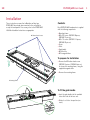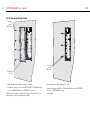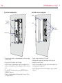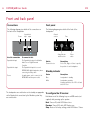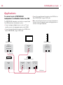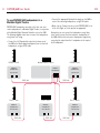
1
DSP520/640
DSP Loudspeaker
User Guide
EN
DSP520/640 User Guide
Important safety instructions
•
•
•
•
•
•
•
•
•
•
•
•
•
Read these instructions.
Keep these instructions.
Heed all warnings.
Follow all instructions.
Do not use this apparatus near water.
Clean only with a dry cloth.
Do not block any ventilation openings. Install in accordance with the
manufacturer’s instructions.
Do not install near any heat sources such as radiators, heat registers,
stoves, or other apparatus (including amplifiers) that produce heat.
Do not defeat the safety purpose of the polarized or grounding-type
plug. A polarized plug has two blades with one wider than the other.
A grounding type plug has two blades and a third grounding prong.
The wide blade or the third prong are provided for your safety. If the
provided plug does not fit into your outlet, consult an electrician for
replacement of the obsolete outlet.
Protect the power cord from being walked on or pinched particularly
at plugs, convenience receptacles, and the point where they exit
from the apparatus.
Only use attachments/accessories specified by the manufacturer.
Unplug this apparatus during lightning storms or when unused for
long periods of time.
Refer all servicing to qualified service personnel. Servicing is required
when the apparatus has been damaged in any way, such as powersupply cord or plug is damaged, liquid has been spilled or objects have
fallen into the apparatus, the apparatus has been exposed to rain or
moisture, does not operate normally, or has been dropped.
WARNING: TO REDUCE THE RISK OF FIRE OR ELECTRIC SHOCK,
DO NOT EXPOSE THIS APPARATUS TO RAIN OR MOISTURE.
The DSP520/640 is designed to be installed using the Meridian
RF500/600 wall box only.
This apparatus has been designed with Class 1 construction and must
be connected to a AC supply socket outlet with a protective earthing
connection (the third grounding pin).
The DSP520/640 must be connected to an earthed AC supply socket
outlet.
An all pole AC supply switch with a contact separation of at least 3mm
in each pole shall be incorporated into the electrical installation on the
building.
Safety warnings
• Do not expose the unit to dripping or splashing.
• Do not place any object filled with liquid, such as a vase, on the unit.
• Do not place naked flame sources, such as lighted candles, on
the unit.
• To avoid overheating leave at least 10cm around the equipment to
ensure sufficient ventilation.
• Do not position the unit in direct sunlight, near heat sources such as
a radiator, or directly on top of heat producing equipment, such as a
power amplifier.
• To avoid interference do not position the unit near strong electrical or
magnetic radiation, such as near a power amplifier.
Radio interference
FCC Warning: This equipment generates and can radiate radio
frequency energy and if not installed and used correctly in accordance
with our instructions may cause interference to radio communications
or radio and television reception. It has been type-tested and complies
with the limits set out in Subpart J, Part 15 of FCC rules for a Class
B computing device. These limits are intended to provide reasonable
protection against such interference in home installations.
EEC: This product has been designed and type-tested to comply
with the limits set out in EN55013 and EN55020.
Copyright
Meridian Audio Ltd
Latham Road
Huntingdon
Cambridgeshire
PE29 6YE
England
Copyright © 2013 Meridian Audio Ltd.
Visit us on the Web:
http://www.meridian-audio.com
Part no: P88411
This guide was produced by: Human-Computer Interface Ltd,
http://www.interface.co.uk/
EN
DSP520/640 User Guide
Installation
These instructions assume that a Meridian wall box type
RF500/600 has already been mounted in the wall ready to
accept the loudspeaker. If necessary, refer to the RF500/600
Wall Box Installation Instructions as appropriate.
M5 button-head screws
Contents
Each DSP520/640 loudspeaker is supplied
with the following components:
• Mounting frame.
• M5 x 25 screws (DSP520 8 pieces,
DSP640 12 pieces).
• M5 x 10 screws (DSP520 14 pieces,
DSP640 20 pieces).
• Scrim.
• Grille.
• Grab handle.
• M3 Allen Key.
• M3 hexagonal driver.
To prepare for installation
• Remove the M5 button-head screws
(DSP520 4 pieces, DSP640 6 pieces)
to release the mounting frame, using the
supplied hexagonal driver.
• Remove the mounting frame.
Mounting frame
To fit the grab handle
• Insert the grab handle into the available
holes either side of the bass unit.
• Rotate it so it locks into position (see
insert).
DSP520/640 User Guide
EN
To fit the mounting frame
Clamping
screws
(M5 x 25)
Mounting
frame
Locking
screws
(M5 x 10)
• Slide the mounting frame into the wall box.
Once the frame is tight against the wall:
• Clamp the frame to the wall with the M5 x 25 button-head
screws (DSP520 8 pieces, DSP640 12 pieces).
• Lock into place with M5 x 10 button-head screws (DSP520
6 pieces, DSP640 8 pieces).
Tighten just enough to clamp the frame to the wall. Do not
overtighten as this may distort the frame.
• Lock tight.
DSP520/640 User Guide
EN
To fit the loudspeaker
To fit the scrim and grille
Scrim
Clamping
screws
(M5 x 10)
Grille
Magnet
positions
Grab handle
• Using the grab handle, sit the loudspeaker on the lower edge
of the wall box.
• Plug in the RJ45 cable(s) and AC supply.
• With the aid of the grab handle, slide the loudspeaker into
position, inserting the top of the loudspeaker into the wall box
first.
• Fix with M5 x 10 button-head screws (DSP520 8 pieces,
DSP640 12 pieces).
• Remove the grab handle to fit the last pair of screws. This is
no longer required.
• Lay the scrim into the back of the grille.
• Carefully hold the grille with your fingers at the top, also
holding the scrim in place.
• Locate the lower edge of the grille at the bottom edge of the
mounting frame for alignment.
• Lay the grille gently down onto the magnets, which will hold it
in place.
DSP520/640 User Guide
EN
Front and back panel
Connections
Front panel
The following diagram gives details of the connections on
the back of the loudspeaker:
The following diagram gives details of the front of the
loudspeaker:
Power
Channel
selector
SpeakerLink
input output
Right
Fuse
Fuse
On
CAUTION:
Disconnect supply before changing fuse.
Replace with same type fuse.
ATTENTION:
Débrancher avant de remplacer le fusible.
Utiliser un fusible de rechange
du même type.
Off
~50-60Hz T5.0AH
250V for 100-230V~
Centre
Input
Output
Left
Use this connection
To connect to this
SpeakerLink input
The SpeakerLink output of a Meridian
Audio Core or Digital Surround
Controller.
SpeakerLink output
Power
The SpeakerLink input of a second
DSP520/640 digital loudspeaker, when
connecting in a daisy-chain.
A captive power cord to connect to the
RF500/600 wall box power outlet.
The loudspeakers are switched on or into standby as appropriate
via the SpeakerLink connections by the Meridian system they
are connected to.
Status indicator
and IR receiver
Power
switch
Switch
Description
Channel selector
Set to Left, Right, or Centre to specify
the position of each loudspeaker.
Standby indicator
Status
Description
Blue
Loudspeaker in standby.
White
Loudspeaker operating.
At power-up flashes once if IR is off and
twice if IR is on.
To configure the IR receiver
Hold down one of the following keys on an MSR remote (not
supplied) while powering up the speaker:
Next: Turns on IR; white LED flashes twice.
Previous: Turns off IR; white LED flashes once.
Stop: Resets all to factory settings; white LED flashes 3 times. DSP520/640 User Guide
EN
Applications
To connect a pair of DSP520/640
loudspeakers to a Meridian Audio Core 200
• Connect the upper SpeakerLink output on the AC200 to the
Slave DSP520/640, using an RJ45 cable.
The DSP520/640 loudspeakers are ideal for a compact Audio
Core 200 based home entertainment system.
• Make sure the Channel selector is set to the Left position on
the front of the left loudspeaker and to the Right position on
the front of the right loudspeaker.
• Connect analogue and digital sources, such as a TV and
satellite receiver, to the appropriate inputs on the AC200.
• Connect the lower SpeakerLink output on the AC200 to the
Master DSP520/640, using an RJ45 cable.
DSP520 – Slave
TV
DSP520 – Master
MERIDIAN
SPEAKERLINK
ANALOGUE
OUT
MERIDIAN
SPEAKERLINK
INPUT OUTPUT
INPUT OUTPUT
RJ45 cable
Satellite Receiver
DIGITAL
OUT
Meridian Audio Core 200
ANALOGUE
IN
DIGITAL
IN
SPEAKERLINK
IN
OUT
RJ45 cable
DSP520/640 User Guide
EN
To use DSP520/640 loudspeakers in a
Meridian Digital Theatre
• Connect the appropriate SpeakerLink outputs on the G68 to
each of the remaining loudspeakers, using RJ45 cables.
DSP520/640 loudspeakers are ideal as the front, rear, and
centre loudspeakers in a Meridian Digital Theatre, in conjunction
with a Meridian Digital Surround Controller such as the G68.
The following diagram shows how to connect the loudspeakers
using “home run” wiring.
• Connect the L+R SpeakerLink output on the lower row of
the G68 to the Master digital loudspeaker (here the front left
loudspeaker), using an RJ45 cable.
• Make sure the Channel selector on each DSP520/640 is set
to the Left, Right, or Centre position as appropriate.
Alternatively you can connect the loudspeakers using “daisy
chain” wiring: connect the front and rear L loudspeakers to
the G68, and then link each pair of loudspeakers together by
connecting the output from the L loudspeaker to the input of
the R loudspeaker.
Meridian Surround Controller
DSP520 – Rear R
MERIDIAN
SPEAKERLINK
DSP520 – Rear L
MERIDIAN
SPEAKERLINK
MERIDIAN
SPEAKERLINK
INPUT OUTPUT
INPUT OUTPUT
RJ45 cable
RJ45 cable
Front R – Slave
Centre – Slave
Front L – Master
MERIDIAN
SPEAKERLINK
MERIDIAN
SPEAKERLINK
MERIDIAN
SPEAKERLINK
INPUT OUTPUT
INPUT OUTPUT
INPUT OUTPUT
RJ45 cable
RJ45 cable
RJ45 cable
DSP520/640 User Guide
EN
To create a Sooloos system
to the rest of your network, or to your Cable/DSL Modem.
The DSP520/640 loudspeakers can be used in conjunction
with an 818 Reference Audio Core to make a superb Sooloos
system.
• Connect the upper SpeakerLink output from the 818
Reference Audio Core to the Master DSP520/640
SpeakerLink input, using an RJ45 cable.
You can control music from the 818 Reference Audio Core, or
browse and control music using the Sooloos application on an
iPad, iPhone, or iPod Touch, or the Control:PC/Control:Mac
application on a computer.
• Connect the lower SpeakerLink output from the 818
Reference Audio Core to the SpeakerLink input of the Slave
DSP520/640, using an RJ45 cable.
• Connect the Network sockets from the Media Core 200 and
the 818 Reference Audio Core to LAN network connections
on your Router, using network cables.
• Make sure the WAN/Internet port on the Router is connected
Router
• Make sure the Channel selector on each DSP520/640 is set
to the Left position on the front of the left loudspeaker and to
the Right position on the front of the right loudspeaker.
For information on configuring your Media Core 200 please
refer to the Media Core 200 User Guide.
Media Core 200
Internet
NETWORK
DSP520 – Slave
Meridian 818 Reference Audio Core
MERIDIAN
SPEAKERLINK
MERIDIAN
SPEAKERLINK
SOOLOOS
NETWORK
DSP520 – Master
SPEAKERLINK
OUT
MERIDIAN
SPEAKERLINK
INPUT OUTPUT
INPUT OUTPUT
RJ45 cable
RJ45 cable
10
DSP520/640 User Guide
EN
EN
DSP520/640 User Guide
11
12
DSP520/640 User Guide
EN