1
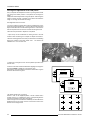
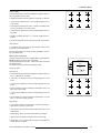
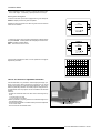
DATA
3300DLC
R9001459
INSTALLATION MANUAL
BARCO PROJECTION SYSTEMS
DATA
3300DLC
R9001459
INSTALLATION MANUAL
Date :
121098
Art. No. :
R5975129A
Federal communication commission (FCC statement)
This equipment has been tested and found to comply with the limits for a class B digital device, pursuant to Part 15 of the FCC Rules. These
limits are designed to provide reasonable protection against harmful interference when the equipment is operated in a commercial environment.
This equipment generates, uses, and can radiate radio frequency energy and, if not installed and used in accordance with the instruction
manual, may cause harmful interference to radio communications. Operation of this equipment in a residential area is likely to cause harmful
interference in which case the user will be required to correct the interference at his own expense.
Instructions to the user :
if this equipment does cause interference to radio or television reception, the user may try to correct the interference by one or more of the
following measures :
-
Re-orientation of the receiving antenna for the radio or television.
Relocate the equipment with respect to the receiver.
Plug the equipment into a different outlet so that the equipment and receiver are on different branch circuits.
Fasten cables connectors to the equipment by mounting screws.
Note :
The use of shielded cables is required to comply within the limits of Part15 of FCC rules and EN55022.
Due to constant research, the information in this manual is subject to change without notice.
Produced by BARCO NV, October 1998.
All rights reserved.
Trademarks are the rights of their respective owners.
BARCO nv/Projection Systems
Noordlaan 5
B-8520 Kuurne
Belgium
Tel : +32/56/368211
Fax : +32/56/351651
E-mail : [email protected]
Visite Barco at the web : http://www.barco.com
Printed in Belgium
Table of Contents
i
TABLE OF CONTENTS
TABLE OF CONTENTS .............................................................................................................................................................................. i-1
INSTALLATION MODE ............................................................................................................................................................................. 1-1
Starting up the Installation Mode ................................................................................................................................................... 1-1
Configuration ................................................................................................................................................................................. 1-1
Internal Patterns ............................................................................................................................................................................ 1-1
How to use the built-in adjustable lensholder .............................................................................................................................. 1-2
HARDWARE SET UP ................................................................................................................................................................................ 2-1
How to activate the password function ...................................................................................................................................... 2-1
5975129A BARCODATA 3300DLC 121098
i-1
Installation Mode
1
INSTALLATION MODE
Starting up the Installation Mode
Push the control disc up or down to highlight Installation and then
press ENTER.
ENTER continues to the Installation mode selection menu.
EXIT returns to operational mode.
ADJUSTMENT MODE
Select a path from below :
RANDOM ACCESS
INSTALLATION
SERVICE
Source 01
The following item can be selected in the Installation mode :
INSTALLATION
INPUT SLOTS
CONVERGENCE
CONFIGURATION
OSD COLOR
INTERNAL PATTERNS
NO SIGNAL [BLACK]
Input slots : to set up the input for a specific source. See
'Connections' for the different source types.
Convergence : to adjust the convergence of the LCD panels. For
more information contact an authorised BARCO service technician.
Configuration : to set up the projector position.
OSD color : to change the color of the highlighted item.
Internal Patterns :
- outline
- color bars
- multiburst
- checker board
- purity
- Page Char
- Alpha-numeric Char
- gray bars
No signal : to display a black or blue screen when no source is
connected to the projector.
Select with
or
then <ENTER>
<EXIT> to return.
Only the items used during the physical installation will be explained
hereafter. The other items are explained in the owners manual.
Configuration
Highlight "Configuration" by pushing the control disc up or down and
press ENTER to select.
INSTALLATION
For more information, see Projector configuration in chapter Installation Set Up.
INPUT SLOTS
CONVERGENCE
CONFIGURATION
OSD COLOR
INTERNAL PATTERNS
NO SIGNAL [BLACK]
Select with
or
then <ENTER>
<EXIT> to return.
Internal Patterns
The projector is equipped with different internal patterns which can be
used for measurment purposes.
Highlight "Internal Patterns" by pushing the control disc up or down
and press ENTER to display the Internal Pattern selection menu.
The following test pattern are available :
- Outline
- Color Bars
- Multiburst
- Checker Board
- Purity
- Page Char
- Alpha-numeric Char
- Gray bars
Each pattern (except Purity) can be inverted by pressing ENTER.
To return to the normal pattern, press EXIT.
5975129A BARCODATA 3300DLC 121098
INSTALLATION
INPUT SLOTS
CONVERGENCE
CONFIGURATION
OSD COLOR
INTERNAL PATTERNS
NO SIGNAL [BLACK]
INTERNAL PATTERNS
OUTLINE
COLOR BARS
MULTIBURST
CHECKER BOARD
PURITY
PAGE CHAR
ALPHA-NUMERIC CHAR
GRAY BARS
Select with
or
then <ENTER>
<EXIT> to return.
2-1
Installation Mode
Convergence adjustment of the LCD panels.
Every LCD panel has 6 adjustment screws. By turning these screws
you change the relative position of the panels and converge the
image.
Always start with the adjustment of the green panel. When the green
image is correctly focused, it will later on be used as the reference
image to converge the red and blue image.
Next alignments have to be done :
You have to adjust the green panel until the indicated lines on the
screen are focused (sharp lines). Continue with the blue panel and
adjust until the blue lines coincide with the green lines. Than continue
with the red panel until the red lines coincide with the green lines.
Follow the next procedure to adjust the LCD panels.
* Open the top cover as described in Gaining access to the DIP
switches under Connecting to a computer in chapter Connections.
The three mounting parts for the LCD's (two are shown on the drawing
below) are located on the black metal cover. The screws are
indicated from 1 to 6 for each color.
33 MM
To adjust the convergence, there are test patterns provided in the
service menu.
Push the control stick forward or backward to hightlight Convergence
and press ENTER to display the Convergence menu.
Start with the Green test pattern and continue with the Blue on green
and finish with the Red on green.
INSTALLATION
INPUT SLOTS
CONVERGENCE
CONFIGURATION
OSD COLOR
INTERNAL PATTERNS
NO SIGNAL [BLACK]
CONVERGENCE
GREEN
BLUE ON GREEN
RED ON GREEN
HATCH
Select with
or
then <ENTER>
<EXIT> to return.
The pattern shows lines of one pixel.
Near six lines on the displayed pattern, a screw is drawn with a
number next to it (e.g. if displayed in green = corresponding with the
screws and numbers on the green LCD panel).
When turning a screw in the direction marked by the arrow above the
displayed screw on the screen, the line on the screen moves in the
direction of the straight arrow.
2-2
5975129A BARCODATA 3300DLC 121098
Installation Mode
Green focusing
a. Insure all convergence screws are adjusted to a length of about 33
mm (1.3") between the two plates.
b. Adjust the projection lens until optimal focus for point 1 is obtained.
c. Turn screw 2 for optimal focus of the corresponding green line 2
on the screen.
d. This alignment influences the other, so repeat if necessary steps
b. and c. until points 1 and 2 are focused.
e. Turn screw 3 for optimal focus of the corresponding green line 3 on
the screen.
f. Repeat if necessary the steps b. to e. until the complet screen is
focused.
g. Secure the projection lens by turning the fastener ring clockwise.
Green position
a. If necessary turn screw 5 until the two horizontal lines 5 on the
screen are on one horizontal line.
When the green pattern is correctly focused, press EXIT to return to
the Test pattern menu.
Blue on green convergence.
Push the control disc up or down to hightlight Blue on green and press
ENTER to display the Blue on green test pattern.
The longest lines are the blue lines. These lines must be converged
with the green lines.
The drawn screws and numbers are displayed in blue.
CONVERGENCE
GREEN
BLUE ON GREEN
RED ON GREEN
HATCH
Follow next steps :
Select with
or
then <ENTER>
<EXIT> to return.
Blue focusing
a. Insure all convergence screws are adjusted to a length of about 33
mm (1.3") between the two plates.
b. Turn screw 1 for optimal focus of the corresponding point 1 on the
screen.
c. Turn screw 2 for optimal focus of the corresponding point 2 on the
screen.
d. Due to interaction, it may be necessary to repeat step b. and c. until
point 1 and 2 are focused.
e. Turn screw 3 for optimal focus of the corresponding point 3 on the
screen.
f. Due to interaction, it may be necessary to repeat steps b. to d. until
point 1, 2 and 3 are correctly focused.
Blue position
g. Turn screw 4 until the red horizontal line coincide with the green
horizontal line in point 4 on the screen.
h. Turn screw 5 until both horizontal lines marked with 5 are on one
horizontal line.
i. Repeat step g. and h. until the horizontal lines are converged.
j. Adjust screw 6 for optimal convergence of the vertical lines.
k. Repeat step i. and j. until a optimal convergence in horizontal and
vertical direction is obtained.
5975129A BARCODATA 3300DLC 121098
2-3
Installation Mode
l. Due to interaction, turning on screw 4, 5 and 6 can influence the
focus of the image. If necessary, repeat procedure from step b. .
Red on green convergence.
Push the control disc up or down to highlight Red on green and press
ENTER to display the Red on green test pattern.
Repeat the same procedure as for Blue on green lines but read red
when blue is indicated.
CONVERGENCE
GREEN
BLUE ON GREEN
RED ON GREEN
HATCH
Select with
or
then <ENTER>
<EXIT> to return.
To check the result of the convergence adjustments, highlight Hatch
and press ENTER. A hatch pattern will be displayed on the screen.
ENTER : displays a hatch pattern.
EXIT : returns to the service menu.
CONVERGENCE
GREEN
BLUE ON GREEN
RED ON GREEN
HATCH
Select with
or
then <ENTER>
<EXIT> to return.
All lines must be displayed in white, if not so repeat the convergence
adjustment procedure.
How to use the built-in adjustable lensholder.
With the lensholder, it is possible to shift the displayed image up or
down on the screen without moving the projector from its normal
positioin and without any geometric picture distortion. This built-in
feature is particularly useful for use in dual projector configurations or
for applications when the projector cannot be installed in its standard
position.
Features :
- Vertical and horizontal shift of the lens without removing the top
cover,
5 mm left and 5 mm right
15 mm up and 15 mm down.
- Makes it possible to project a geometric non-distored image from a
non-standard position.
- The shift of the lensholder is not determined by the lens but depends
on the screen width.
- Can be used with all available lenses.
2-4
Lens shift up/down
Lens shift left/right
5975129A BARCODATA 3300DLC 121098
Installation Mode
How to shift the image :
- First shift the image left or right until the correct horizontal position
hole
indication
line
is obtained. Turn clockwise to shift the image to the right, turn counter
clockwise to shift to the left. Use the hand screw.
- Shift the image up or down until the correct vertical position of the
image is obtained. Turn clockwise to shift the image up, turn counter
clockwise to shift down. Use the hand screw.
Midposition of the adjustable lensholder.
-If the top cover is opened, the lensholder indication line has to match
with the center of the hole in the plate behind the lensholder.
- If the top cover is closed, the 3 indication lines on the lensholder has
to match with indication on the top cover.
0,5 40
80
120
160
240
200
30
Horizontal Screen Shift
Maximum 5 mm right lens shift
2.5 mm
0,25
Horizontal shift is function of the Screen Width for
various lens shifts.
15
no shift
0
0
-2.5 mm
-15
-0,25
Maximum 5 mm left lens shift
-0,5
-30
1
2
3
4
5
6
Screen Width
1,540
160
200
240
90
10 mm
1
Both the vertical and horizontal shift of the displayed picture can be
calculated as follows :
60
5 mm
0,5
Vertical Screen Shift
LCD panel width for 3200 series : 0,06480 m (2.551 inch)
120
Maximum 15 mm upwards lens shift
Vertical shift is function of the Screen Width for various lens shifts.
Screen shift = lens shift x 1 + (Screen width / LCD panel width)
80
30
no shift
0
0
-0,5
-30
-5 mm
-1
-60
-10 mm
Maximum 15 mm downwards lens shift
-1,5
1
2
3
4
-90
5
6
Screen Width
5975129A BARCODATA 3300DLC 121098
2-5
Hardware Set Up
2
HARDWARE SET UP
How to activate the password function?
The password function can be hardware set with a DIP switch on
the CPU module. To change the position of this DIP switch, it is
necessary to open first the top cover.
Gaining access to the DIP switch
Power down the projector and unplug the power cord from the wall
outlet.
Turn both lock screws with a screwdriver or coin counter
clockwise.
Lift up and pivot the top cover. Attention : the cover is not secured
with an incorporated support. When opening, turn it over slowly.
The processor module with the DIP switches is located on the front
side.
Loosen the locking
screws.
Open the top cover
When DIP switch 1 is in the :
- ON position, password is activated.
-OFF position, password not activated, service mode
is free accessible.
1
On
Off
5975119A BARCODATA 3300LC 121098
2-1