1
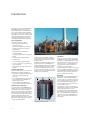
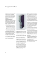
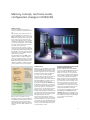
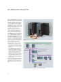
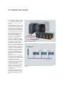
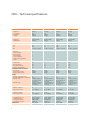
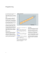
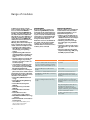
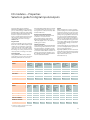
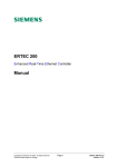
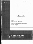
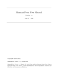
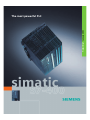
Product Brief · January 2003
The most powerful PLC
Introduction
The S7-400® is the most powerful PLC in
the SIMATIC® Controller family; the
range that enables successful automation solutions with Totally Integrated
Automation. The S7-400 is an automation platform for system solutions in the
manufacturing and process industries,
and is distinguished above all by its
modularity and performance reserves.
Areas of application
Application areas are found in
· the automobile industry (e.g.
production lines)
· mechanical engineering, including
specialist machine construction
· warehousing
· building systems automation
· the steel industry
· energy generation and energy distribution
· the paper and printing industry
· woodworking
· the food and beverages industry
· process engineering, e.g. water supply and disposal
· the chemical and petrochemical industries
Specialist applications
There are other versions of the S7-400
available for specialist applications:
· Applications requiring fault tolerance
can be implemented with the
S7-400H
· For failsafe applications, there is the
S7-400F that is also available in a
fault-tolerant version
· S7-400 CPUs are available as PC
plug-in cards for PC-based solutions
Storage of all project data, including
symbols and comments, on the CPU
makes service and maintenance work
palpably easier.
In addition, powerful integrated system
diagnostics functions guarantee increased availability of the controller and
therefore greater productivity. To this
are added configurable process diagnostics functions for analysis of process
faults in order to reduce downtimes and
further boost productivity.
PS
SM
CPU
Configuration of the S7-400
2
An S7-400 system consists basically of a
backplane, a power supply, and a CPU.
The system is modular and can be set up
easily without the need to observe slot
rules. The S7-400 is characterized by
rugged fan-free operation with hot
swapping of signal modules.
A diverse range of modules can be used
both for centralized expansions and for
easy setup of distributed structures with
the ET 200®; this results in extremely
low-cost spare parts inventory.
Modularity
Engineering and diagnostics
In conjunction with the SIMATIC Engineering Tools, the S7-400 results in extremely efficient configuring and programming, particularly in extensive automation solutions with a high proportion of engineering. Examples include
high-level languages like SCL and
graphical Engineering Tools for sequential controls, state diagrams and technology-oriented diagrams.
Installation
CP
Modularity is an outstanding feature of
the S7-400. The powerful backplane
bus of the S7-400, and the communications interfaces that can be connected
direct to the CPU, allow high-performance operation of a large number of
communications lines.
This makes it possible, for example, to
break up the system into a line for HMI
and programming tasks, one for
high-performance and equidistant motion control components, and one for
the "normal" I/O field bus. Additionally
required connections to MES/ERP systems or to the Internet can also be implemented.
CPU performance
There is a graded range of CPUs available for controller design, from the entry-level CPU right up to the high-performance CPU. All CPUs have large quantity structures, and several CPUs can work
together in multicomputing configurations in order to boost performance.
The CPUs enable short machine cycle
times, thanks to their efficient processing speed and deterministic response
times.
Memory in MB
4.0
3.2
1.6
0.75
Range of CPUs
All the CPUs have a combined programming and PROFIBUS DP interface. This
means they can be accessed at any time
from the OP or programming device/PC
or networked with various controllers.
This interface can also be used for connecting distributed PROFIBUS DP devices. This means that all the CPUs can be
operated directly with distributed I/O.
All the CPUs, except the entry level
CPU 412-1, also incorporate a PROFIBUS
DP interface whose main function is to
act as the interface to distributed I/O,
but which can also be configured to be
used for communications with the OP or
programming device/PC.
The higher-end CPUs also have free
slots for PROFIBUS DP interface modules
in order to connect additional DP lines.
Otherwise, the only difference between
the CPUs is the performance scope, e.g.
RAM, address range, number of modules which can be connected and processing time.
Multi-computing
Multi-computing, i.e. running more
than one CPU in a S7-400 central controller, has a number of benefits to the
user.
· Multi-computing means that the
overall performance of an S7-400 can
be split up. For example, complex
technical functions, such as controlling, computing or communicating,
can be separated and assigned to different CPUs. And each CPU can be assigned its own, local I/O.
· Multi-computing also enables different functions to be separated from
one another, so, for example, one
CPU can process the time- critical processing functions and another CPU
the non-time critical functions.
Binary instruction processing
time in Ns
0.25
Number of
blocks in K
0.1
16
8
3
1
0.2
0.1 0.08
4
8
16
Address range in KB
Range of S7-400 CPUs
In multi-computing mode, all the CPUs
together act as a single CPU, i.e. if one
CPU goes into STOP mode, all the other
CPUs stop at the same time. Synchronization calls enable the actions of multiple CPUs to be coordinated for each individual instruction.
At the same time, data transfer between the CPUs is extremely fast thanks
to the “Global Data” mechanism.
Performance
The S7-400 stands out not only for its
short response times, but also for its
large performance reserves. Very short
response times can be attained, even
when simultaneous communication is
required, or other unforeseeable loads
occur. This, in turn, makes it possible to
obtain specific response times, e.g. the
response of an output signal to a
change in input signal.
Diagnostics
The CPUs’ intelligent diagnostics system
continuously monitors the functionality
of the system and the process, and registers errors and specific system events
(CPU black-box); there is also the option
of adding extra diagnostic messages.
The diagnostics function can determine
whether the signal logging (for digital
modules) or analog processing (analog
modules) functions of the module are in
good working order. In the event of a diagnostics message (e.g. “no supply to
encoder”), the module triggers a diagnostics interrupt
The CPU then interrupts the processing
of the user program and executes the
appropriate diagnostics interrupt block.
Process interrupts mean that process
signals can be monitored and reactions
to signal changes can be triggered.
3
Integrated interfaces
On the other hand, following integration of the DP V1 functions according to
IEC 1158 Parts 3-6, new, standardized
PROFIBUS DP functions are now also
available in the S7-400 for communication with non-Siemens systems.
In automation, there is a trend towards
distributed systems. The SIMATIC
S7-400 supports the required data
exchange between distributed systems.
Interfaces integrated directly into the
CPUs mean you can set up a high-performance communications environment using conventional bus
technology.
Furthermore, the operating parameters
of field devices can be modified during
operation, thus reducing conversion
times. Finally, expanded diagnostics
functions facilitate troubleshooting and
help reduce down times.
The programming interface
All CPUs have a combined programming
and PROFIBUS DP interface which can
be accessed at any time by up to 125
programming devices/PCs or OPs and
can also be networked with other controllers. This interface can also be used
for connecting up to 31 distributed
PROFIBUS DP devices.
· By means of data communication,
this interface enables the transfer of
process data between various different controllers, e.g. one CPU can access the inputs or outputs of another
CPU.
· The programming interface also has
all the functionality of a DP interface.
Communications interface modules
Communications interface modules can
be used optionally in the S7-400 CPUs in
order to adapt them to the requirements of the application in hand.
The CPUs 414-3 and 416-3 have one
free slot, and the CPU 417-4 has two
free slots for this purpose. By connecting such interface modules, additional
DP lines can be established as master or
slave whose functionality corresponds
to that of the integral interface.
Shared functions
CPU 417-4 with integrated interfaces
PROFIBUS DP interface (or “centralized
= distributed”)
In terms of configuration and programming, there is no difference between
centralized and distributed I/O.
To make setting up relatively large distributed structures economically viable,
the SIMATIC S7-400 can be connected
as a master to the PROFIBUS DP open
field bus (in accordance with EN
50170). This allows communications
with a number of partners, from the
SIMATIC controller to field devices from
other manufacturers. Up to 125 stations
can be controlled by one DP interface.
More than 400 PROFIBUS slaves can be
connected to a CPU with 4 interfaces;
this means an S7-400 station can drive
more than 1600 PROFIBUS slaves.
Firmware release V 3.0 and later (from
July 2001) provides the S7-400 with
even more networking functionalities.
On the one hand, the S7-400 can now
also be used as an intelligent slave on
PROFIBUS DP, permitting intelligent,
distributed preprocessing.
4
PG functions, e.g. programming by programming device/PC over long distances, are possible using either interface
type. A programming device (PG) can
also operate more than one CPU, or
more than one programming device
can access a CPU.
There is also a routing function whereby
a programming device connected to
any point in the network can access all
the stations on the network.
HMI functions are already integrated
into the operating system of the S7-400
and transfer data to connected SIMATIC
Operator Panels or Operator Stations
without the need for any programming.
As with the PG functions, the control
and monitoring functions are compatible with either the programming or the
DP interface.
For all panels in the SIMATIC HMI range,
the configuration software used is
SIMATIC ProTool/Pro® - a consistent,
uniform, Windows-based system which
accesses the STEP 7 database and thus
avoids duplicate entries.
More advanced functions, e.g. connection to bus systems, can be achieved using communications modules.
Memory concept, isochrone mode,
configuration changes in RUN (CiR)
Memory concept
All S7-400 CPUs have two types of
memory: load memory and main memory.
This splitting of the main memory improves performance by around 100 %.
While a standard processor accesses its
RAM memory at least twice, the special
S7-400 processor accesses the code
memory and the data memory simultaneously in a single cycle. This is made
possible by the separate code and data
bus. This is direct performance which is
of benefit to the customer!
The size of the main memory is determined by selecting the appropriate CPU
from the finely graded range of CPUs. In
the CPU 417, the main memory can be
expanded to up to 20 MB by slotting in
extra memory modules.
The integrated memory (RAM) is adequate for small to medium-sized programs. For larger programs, the memory can be increased by slotting in extra
RAM. Additional plug-in flash memory
cards are available to enable retentive
memory without the use of a battery.
Isochrone mode: Securely handles fast processes
Isochrone mode
External load
memory
battery-backed
RAM or retentive
Flash Memory
·
Integrated load
memory
battery-backed
RAM
Load memory
for project data
(blocks,
symbols,
comments,
configuration,
parameterization data, etc.)
customer files
·
·
·
Main memory, code
50 % for program
non-backed RAM
·
·
Main memory, data
50 % for data
battery-backed RAM
Main memory
for processrelated modules, process
image, local
data
·
·
·
Memory types for the SIMATIC S7-400
The S7-400, as the most powerful PLC in
the SIMATIC controller family, offers important new system functions when
used with the new operating system 3.1
and in conjunction with other TIA components:
The S7-400 is now capable of providing
distributed I/O solutions with the capability to handle extremely fast processes
with very high precision. Consequently,
production can be enhanced while at
the same time increasing quality.
This was made possible by the new system function denoted „isochrone
mode“. Isochrone mode means that the
distributed I/O devices obtain signal inputs and outputs synchronously
through the equidistant PROFIBUS and
forward these signals for synchronous
processing in the PLC. This way, all input
signals are read, processed synchronously, and in concert with the output
signals. Process response times are
therefore reproducible and defined, and
you can be assured that the distributed
I/O system will process signals synchronously and at the same time.
The precise reproducibility of all processes, even very fast ones, is no longer
a problem. Many components now support isochrone mode, enabling the user
to handle many applications in the area
of motion control, measurement technology and loop control.
Hardware configuration changes in RUN
(Configuration in RUN, CiR)
Another new feature is that SIMATIC
S7-400 now allows hardware reconfigurations without any adverse effects
while in run mode, e.g. to implement
new sensors or actuators. CiR - Configuration in RUN - reduces time needed for
commissioning and retrofit because
these changes can now be undertaken
while the plant is in full operation. Also,
this new system function makes it possible for technicians to respond to process changes and implement process
optimizations very easily since the plant
must not be re-initialized and synchronized when hardware is changed.
It is possible to add and remove distributed I/O stations (PROFIBUS DP and
PROFIBUS PA slaves), to add and remove
individual I/O modules in the I/O system
ET 200M, and to assign new parameters
(e.g. to select other interrupt
thresholds).
5
S7-400H fault tolerant PLC
Based on standard S7-400 modules, the
S7-400H is a fault tolerant (redundant)
PLC which drastically reduces the risk of
production downtime. Its fault tolerant
structure makes the S7-400H ideally
suited to applications in which MTTR
and downtimes need to be reduced or
avoided where possible, e.g. for energy
generation / distribution, the chemical
industry, mining, transport, etc.
The fault tolerance is achieved by
means of two parallel central controllers whose CPUs are connected by
means of fiber optic conductors and
which control the I/O through redundant PROFIBUS DP lines. Redundant I/O
is presently under development. Once
this is available, it will be possible to
compensate failing I/O in addition to
failing CPU and PROFIBUS. In the event
of an error, there is a bumpless transfer
of control, i.e. the intact standby device
takes over execution at the point of interruption, with no loss of information.
When setting up a fault-tolerant
S7-400H controller, the user can concentrate entirely on the job in hand:
· The S7-400H is programmed in the
same way as a non-redundant standard S7-400 system using any STEP 7
language.
All redundancy-specific functions can
be configured using a easy-to-use
STEP 7 option package. A program
written for a standard non-redundant
system can easily be ported to a redundant system (and vice versa).
· The S7-400H consists almost exclusively of standard components from
the SIMATIC S7 range and is an integral part of Totally Integrated Automation® (TIA).
Further information can be found in the
Product Brief “SIMATIC S7-400H and
S7-400F/FH - Top end controllers with
fault tolerant and fail-safe functionalities”.
SIMATIC S7-400H fault tolerant PLC
SIMATIC S7-400H
I/O station with redundant
interface
Y link
PA link
Configuration of SIMATIC S7-400H with in-circuit connection of I/O
6
S7-400F/FH fail-safe PLC
The new SIMATIC S7-400F/FH is an addition to the range of SIMATIC S7 controllers. It is a fail-safe controller based on
the technology of the fault tolerant
S7-400H.
The SIMATIC S7-400F/FH enters a safe
state immediately when an error occurs
or remains in a safe mode, thus guaranteeing a high level of safety for man,
machine, the environment and the process. The S7-400F/FH has a TÜV approval (TÜV = German Technical Inspectorship) and fulfills all relevant standards.
The S7-400F/FH can also be used as a
standard or fault tolerant controller.
This means that the SIMATIC
S7-400F/FH combines standard automation functions and safety-related
technology in a single system.
The CPUs of the SIMATIC S7-400F/FH
are based on the CPUs of the SIMATIC
S7-400H system (CPU 414-4H, 417-4H),
with the addition of what is known as
an F-library. This F-library contains
pre-assembled, TÜV-approved basic
function blocks as well as a parameterization tool for the fail-safe I/O modules.
The CFC Engineering Tool is used to call
blocks from the F-library and interconnect them, i.e. there is no additional familiarization time for the programming.
These ET200®M fail-safe I/O modules
are connected to PROFIBUS and controlled by means of the new PROFISafe
PROFIBUS profile for safety-related
applications.
There is also an additional advantage in
the fact that a S7-400F/FH fail-safe controller largely consists of standard components and is an integral part of Totally
Integrated Automation (TIA).
This means the S7-400F/FH can now be
used for areas of automation which, up
to a few years ago, were the exclusive
domain of conventional electro-mechanical controllers, e.g. automobile shell construction using presses
and robots, burner management systems, transportation of persons on
cableways and, last but not least, process automation.
Further information can be found in the
Product Brief “SIMATIC S7-400H and
S7-400F/FH - Top end controllers with
fault tolerant and fail-safe functionalities”.
SIMATIC S7-400F/FH fail-safe PLC
F-compatible S7-400H
CPU (CPU 417-4H)
Standard SMs
F-SMs (DI, DO, AI)
Standard PROFIBUS DP connection of I/Os with additional fail-safe DP communication
(PROFIsafe)
7
CPUs - Technical specifications
CPU 412-1
CPU 412-2
CPU 414-2
CPU 414-3
Main memory
integrated
in instructions
for program
for data
·
·
·
·
96 Kbyte
32 K
48 Kbyte
48 Kbyte
144 Kbyte
32 K
72 Kbyte
72 Kbyte
256 Kbyte
84 K
128 Kbyte
128 Kbyte
768 Kbyte
84 K
384 Kbyte
384 Kbyte
Load memory
integrated
expandable to
·
·
256 Kbyte RAM
64 Kbyte
256 Kbyte RAM
64 Kbyte
256 Kbyte RAM
64 Kbyte
256 Kbyte RAM
64 Kbyte
Backup
Yes
Yes
Yes
Yes
Number of blocks
FB
FC
DB
·
·
·
256
256
511 (DB 0 reserved)
256
256
511 (DB 0 reserved)
2048
2048
4095 (DB 0 reserved)
2048
2048
4095 (DB 0 reserved)
Program execution
free cycle
timed interrupts
delay interrupts
time interrupts
process interrupts
multi-computing interrupt
startup
·
·
·
·
·
·
·
1
2
2
2
2
1
3
1
2
2
2
2
1
3
1
4
4
4
4
1
3
1
4
4
4
4
1
3
Execution times
bit operations
word operations
fixed point arithmetic
floating point arithmetic
·
·
·
·
2 µs
2 µs
2 µs
3 µs
2 µs
2 µs
2 µs
3 µs
0.1 µs
0.1 µs
0.1 µs
0.6 µs
0.1 µs
0.1 µs
0.1 µs
0.6 µs
Bit memories/timers/counters
Bit memories
S7 timers/S7 counters
IEC timers/IEC counters
4 Kbyte
256/256
SFB/SFB
4 Kbyte
256/256
SFB/SFB
8 Kbyte
256/256
SFB/SFB
8 Kbyte
256/256
SFB/SFB
21
max. 10
limited by number of
slots and number of
connections
limited by number of
slots and number of
connections
21
max. 10
limited by number of
slots and number of
connections
limited by number of
slots and number of
connections
21
max. 10
limited by number of
slots and number of
connections
limited by number of
slots and number of
connections
21
max. 10
limited by number of
slots and number of
connections
limited by number of
slots and number of
connections
Programming interface
Number of stations
Transmission speed
·
·
16
max. 12 Mbit/s
16
max. 12 Mbit/s
32
max. 12 Mbit/s
32
max. 12 Mbit/s
DP interface
Number of stations
Transmission speed
·
·
32
max. 12 Mbit/s
32 + 64
max. 12 Mbit/s
32 + 96
max. 12 Mbit/s
32 + 2 x 96
max. 12 Mbit/s
Address ranges
Total I/O address area
I/O process image
Total digital channels
Total analog channels
·
·
·
·
4 Kbyte /4 Kbyte
4 Kbyte /4 Kbyte
32768/32768
2048/2048
4 Kbyte /4 Kbyte
4 Kbyte /4 Kbyte
32768/32768
2048/2048
8 Kbyte /8 Kbyte
8 Kbyte /8 Kbyte
65536/65536
4096/4096
8 Kbyte /8 Kbyte
8 Kbyte /8 Kbyte
65536/65536
4096/4096
MLFB group
6ES7412-1XF...
6ES7412-2XG...
6ES7414-2XG...
6ES7414-3XJ...
·
·
·
Design
Number of expansion units
Number of DP masters, through CP
Number of FMs
·
·
·
·
8
Number of CPs
CPUs - Technical specifications
CPU 416-2
CPU 416-3
CPU 417-4
Main memory
integrated
in instructions
for program
for data
·
·
·
·
1.6 Mbyte
530 K
0.8 Mbyte
0.8 Mbyte
3.2 Mbyte
1065 K
1.6 Mbyte
1.6 Mbyte
4 Mbyte
1335 K
2 Mbyte
2 Mbyte
Load memory
integrated
expandable to
·
·
256 Kbyte RAM
64 Kbyte
256 Kbyte RAM
64 Kbyte
256 Kbyte RAM
64 Kbyte
Backup
Yes
Yes
Yes
Number of blocks
FB
FC
DB
·
·
·
2048
2048
4095 (DB 0 reserved)
2048
2048
4095 (DB 0 reserved)
6144
6144
8191 (DB 0 reserved)
Program execution
free cycle
timed interrupts
delay interrupts
time interrupts
process interrupts
multi-computing interrupt
startup
·
·
·
·
·
·
·
1
8
4
9
8
1
3
1
8
4
9
8
1
3
1
8
4
9
8
1
3
Execution times
bit operations
word operations
fixed point arithmetic
floating point arithmetic
·
·
·
·
0.08 µs
0.08 µs
0.08 µs
0.48 µs
0.08 µs
0.08 µs
0.08 µs
0.48 µs
0.1 µs
0.1 µs
0.1 µs
0.6 µs
Bit memories/timers/counters
Bit memories
S7 timers/S7 counters
IEC timers/IEC counters
16 Kbyte
512/512
SFB/SFB
16 Kbyte
512/512
SFB/SFB
16 Kbyte
512/512
SFB/SFB
21
max. 10
limited by number of slots and
number of connections
limited by number of slots and
number of connections
21
max. 10
limited by number of slots and
number of connections
limited by number of slots and
number of connections
21
max. 10
limited by number of slots and
number of connections
limited by number of slots and
number of connections
Programming interface
Number of stations
Transmission speed
·
·
64
max. 12 Mbit/s
64
max. 12 Mbit/s
64
max. 12 Mbit/s
DP interface
Number of stations
Transmission speed
·
·
32 + 125
max. 12 Mbit/s
32 2 x 125
max. 12 Mbit/s
32 + 3 x 125
max. 12 Mbit/s
Address ranges
Total I/O address area
I/O process image
Total digital channels
Total analog channels
·
·
·
·
16 Kbyte /16 Kbyte
16 Kbyte /16 Kbyte
131072/131072
8192/8192
16 Kbyte /16 Kbyte
16 Kbyte /16 Kbyte
131072/131072
8192/8192
16 Kbyte /16 Kbyte
16 Kbyte /16 Kbyte
131072/131072
8192/8192
MLFB group
6ES7416-2XK..
6ES7416-3XL...
6ES7417-4XL...
·
·
·
Design
Number of expansion units
Number of DP masters, through CP
Number of FMs
·
·
·
·
Number of CPs
9
Programming
The configuration and programming of
the S7-400 is based on STEP® 7.
STEP 7 offers functions for every phase
of an automation project – from configuration to startup, testing and servicing.
Memory requirement
STEP 7
STEP 7 incorporates the SIMATIC Manager, the central tool for the software-related handling of the project.
This relates not only to a single CPU, but
to the whole plant – irrespective of how
many controllers, drives and HMI devices the solution consists of. Using STEP 7
also ensures that the data is kept consistent throughout the project.
STEP 7 incorporates both the hardware
configuration of the plant and the parameterization of the modules, so there
are no more hardware settings to be
made. STEP 7 also includes the three basic languages: statement list (STL), ladder diagram (LAD) and function block
diagram (FBD). STEP 7 also makes it possible to parameterize high-speed data
communications between networked
CPUs.
Engineering Tools
As the S7-400 is generally used for executing large programs, there are also
higher-level languages and graphical
engineering tools based on STEP 7.
These have the additional functionality
to enable you to program automation
solutions in a function-oriented manner
and using a user-friendly interface.
Productivity
Memory required for engineering tools
The following tools are available for programming:
S7-SCL
(Structured Control Language), PASCAL-based higher-level language for
programming SIMATIC S7/C7 controllers
S7-GRAPH
enables graphical configuration of sequential control systems for SIMATIC
S7/C7
S7-HiGraph®
for graphical description of sequential
or asynchronous process with status diagrams for SIMATIC S7/C7
CFC
(Continuous Function Chart), the technology-oriented diagram which enables
graphical interconnection of complex
functions for SIMATIC S7
10
Data storage
The new STEP 7 Version 5.1 allows any
data to be saved to the CPU, i.e. if you
are servicing or upgrading the system,
the personnel can still access not only
the programs running, but also the
whole project, including any comments
and symbols. If you are using higher-level languages or graphical engineering tools, the program source code
is also immediately available in its original form or in graphical format. Last but
not least, it is also possible to save customer-specific operating instructions,
manuals and machine documentation
directly on the CPU in all standard file
formats.
Communication
Totally Integrated Automation
A single, completely integrated and
consistent system with which you can
execute any automation functions!
An element of central importance within the system is the communications
network:
Industrial Ethernet (IEEE 802-3 and
802.3u) – the international standard for
area and cell networking – with a connection to the IT environment.
S7-400
S7-300®
OS
Data communication
PROFIBUS (IEC 61158/EN 50170) – the
international standard for the cell and
field levels.
PC
OS
AS-Interface (EN 50295) – the interna-
tional standard for communications
with sensors and actuators.
EIB (EN 50090, ANSI EIA 776) – the global standard building installation system and the basis for building services
automation.
S7-400
Scanner
Point to point connection – for commu-
Network access
Process or field communications
Process or field communication are
used to connect actuators/sensors to a
CPU.
Process or field communication with the
S7-400 is supported by PROFIBUS DP. To
make this possible, the S7-400 can be
connected to PROFIBUS DP as a master –
either by means of the interface integrated into each CPU, a special interface
module or a communications processor
(CP). The AS interface and EIB networks
and other bus systems are accessible
from the S7-400 through the PROFIBUS
gateways.
Link
Link
Fire alarm
Data communications
Data communications enable data
transfer between automation systems
or between an automation system and
an intelligent partner (PC, computer,
etc.).
This is achieved either through the programming interface or by means of
PROFIBUS and Industrial Ethernet.
ET 200
Sensor
Process/field communication
nication between two stations with special protocols. The point to point structure represents the simplest form of
communication. Various different special protocols are used (e.g. RK 512,
3694(R) and ASCII).
Communication options for the SIMATIC S7-400
The programming interface enables
simple cyclical data transfer on the one
hand (no acknowledgment) and programmed transfer of relatively large volumes of data on the other (with or without acknowledgment).
Specific communications processors
(CP) are used for the connection to
PROFIBUS and Industrial Ethernet;
which means that the TCP/IP protocol
can be accessed direct from the program.
11
Range of modules
In addition to the range of specific
S7-400 modules, the S7-400 also gives
access to the world of PROFIBUS
through the integrated PROFIBUS DP
interface. This means that a large number of I/O modules are available with
which the S7-400 can be adapted to a
wide range of functions. Users of the
system have access to PROFIBUS DP
modules from Siemens as well as modules from other manufacturers.
Naturally, there is also a wide range of
S7-400 modules which can be used in
central controllers and expansion units:
· intelligent power supplies (redundant, diagnostics-compatible) to secure the supply of all operating
voltages
· digital and analog I/O modules for
nearly all signal types, including some
with interrupt processing and diagnostics
· function modules for counting/ measurement, all types of positioning
functions, cam control, motion control and computing
· communications modules for serial
point to point connection and bus
communications by means of PROFIBUS and Industrial Ethernet
· interface modules for connecting expansion units to the central controller
The following documents contain additional information on the range of modules and on communications:
· Product Brief „SIMATIC based Technology“
· Product Brief “Counting/Measuring
with SIMATIC”
· Product Brief “Positioning with
SIMATIC“
· Product Brief “Loop control with
SIMATIC”
· Product Brief “Cam control with
SIMATIC”
· Product Brief “S7-300/400
point-to-point coupler modules”
· Multi-Media-CD “SIMATIC Technology
... in Action”
· Overview “Industrial communications
for automation”
· Product Brief “Unbeatable performance without limits with
FM 458-1DP in S7-400“
12
Expansion options
Interface to the world of IT
Not only can a S7-400 system be expanded using PROFIBUS DP, but additional racks can also be linked directly to
the central processing unit. Distances of
up to 600 m can be covered without any
performance loss of the backplane bus.
The power supply can also be looped
through for shorter distances.
The S7-400 allows you to integrate the
modern world of IT into automation.
The pluggable CP (CP 443-1 IT®) enables the following functions:
· Creation of your own web pages using any HTML tools, and the process
variables for the S7-400 can simply be
assigned to the HTML objects
· Monitoring of the S7-400 through
these web pages using a standard
browser
· Sending of e-mails from the user program of the S7-400 by means of function calls
· Remote programming through the
telephone network (e.g. ISDN) using
the WAN properties of TCP/IP.
Racks with 18 or 9 slots are available as
the central controller. Using interface
modules, up to 21 expansion units,
each with either 18 or 9 slots for S7-400
modules, can be connected
Communication
Technology
Point to point connection with data rates
of up to 115 Kbit/s and various protocols,
e.g. for connecting modems, printers,
scanners, drives, external devices, etc.
Counting in various modes, up to
500 kHz
Connection to PROFIBUS using either the
DP or the FMS protocol (DP V0 and
DP V1)
Cam control for up to 16 cam lines
per module
Connection to Industrial Ethernet using
the ISO/TCP or TCP/IP data communications protocol
Any type of positioning function:
controlled positioning using the
rapid/creep feed process (3 axes per
module)
Connection to the Internet through Ethernet for loading websites and using
e-mail
Point to point positioning and velocity profiles (position control) with
stepper and servo motors (3 axes per
module)
PID controller with backup functionality and integrated online self-configuration for various types of
controller (continuous controllers,
stepper controllers, pulse controllers)
Freely programmable, highly
dynamic controller for up to 100 axes
per module
I/O modules – Properties
Selection guide for digital inputs/outputs
Signal modules are the interface
between the SIMATIC S7-400 and the
process. A wide range of different digital and analog modules provide exactly
the right inputs/outputs required for the
function in question. However, the
S7-400 signal modules represent only a
subset of the modules which can be
connected to the S7-400 through
PROFIBUS DP.
with individual strands and a completely modular building block system, consisting of front connector module, cable
and terminal block.
High level of packaging density
The large number of channels on the
modules is one reason for the
space-saving design of the S7-400:
Modules are available with 8 to 32
channels (digital) or 8 to 16 channels
(analog) per module.
Easy to install
The sensors/actuators simply connect to
the front connector. When replacing the
module, all you need to do is plug the
connector into the new module of the
same type. You do not need to change
the wiring. The coding of the front connector prevents confusing of modules.
Simple to configure
The modules are configured and parameterized using STEP 7, there are no fiddly switch settings. The data is stored
centrally and automatically transferred
to the new module after a module is replaced, which prevents transfer errors.
No software upgrade is required when
new modules are installed.
Fast connection
Using SIMATIC TOP connect makes it
even easier to connect. You can choose
between prewired front connectors
Alarms
Many modules also monitor signal acquisition (diagnostics interrupt) and the
signals from the process (process interrupt). This means the system can react
quickly to any irregularities and to every
process event. How and whether the
controller reacts can be configured in
STEP 7. For the digital input modules, a
process interrupt can be triggered on a
rising edge, a falling edge or both edges
of a signal status change, or based on
channel groups.
The following pages list criteria to help
you select the appropriate signal module for a given application.
Regularly updated, extensive technical
information can be found in the interactive CA 01 catalog at any time (Internet:
http:// www.siemens.com/
automation/ca01)
Module type
Selection guide for digital inputs
Special features of this
module
Very fast, interrupt-capable
24 V DC
input module
24 V DC standard input module – extremely
high packaging
density
Highest packag- Input module for Interrupting density for
higher, variable capable input
the 120 V market voltages
module for
lower, variable
voltages 1)
Specially for the
US-dominated
AC market channel-oriented
isolation
Type of voltage
DC
DC
UC
UC
UC
AC
Input voltage
24 V
24 V
120 V
120/230 V
24 to 60 V
120 V
Interrupt capability
Yes
No
No
No
Yes
No
Input delay
0.05 to 3 ms 2)
3 ms
< 25 ms
< 25 ms
0.5 to 20 ms 2)
< 25 ms
Number of channels
16
32
32
16
16
16
MLFB group
6ES7 4217BH..-...
6ES7 4211BL..-...
6ES7 4211EL..-...
6ES7 421
1FH..-...
6ES7 4217DH..-...
6ES7 4215EH..-...
Module type
Selection guide for digital outputs
Special features of this
module
DC output
module for
high currents
DC output
module for
variable
voltages
24 V DC
standard
output
module –
high poss.
packaging
density
Very fast,
interruptcapable
24 V DC
input
module
AC output
AC standard
module for output
high
module
currents and
channeloriented
isolation
AC output
Relay output
module for module
variable
voltages
and channel-oriented
isolation
Type of voltage
DC
DC
DC
DC
AC
AC
AC
Relay
Output voltage
24 V
20 - 138 V
24 V
24 V
120/230 V
120/230 V
20-120 V
5-125 VDC
Output current
2A
1.5 A
0.5 A
0.5 A
5A
2A
2A
5A
Interrupt capability
Yes
No
No
Yes
No
No
No
No
Number of channels
16
16
32
32
8
16
16
16
MLFB group
6ES7 4221BH..-...
6ES7 4225EH1.-...
6ES7 4221BL..-...
6ES7 4227BL..-...
6ES7 4221FF..-...
6ES7 4221FH..-...
6ES7 4225EH0.-...
6ES7 4221HH..-...
1)
2)
can also be used as an active low module
can be set with parameters
13
I/O modules – selection guide for analog inputs
Selection guide for analog inputs
Physical
measured variable
Voltage
Special features of this
module
Standard module with
16 inputs
Standard module with
8 inputs
Numerous
voltage ranges
Very rapid analog value
acquisition
Generation of
diagnostics
and process
value interrupts at 16 bit
resolution
Channeloriented isolation and generation of
diagnostic and
process value
interrupts
Measurement range
Encoder
p1 V
1-5V
p1 V
p10 V
p80 mV
p250 mV
p500 mV
p1 V
p2.5 V
p5 V
p10 V
p1 V
1-5V
p10 V
p25 mV
p50 mV
p80 mV
p250 mV
p500 mV
p1 V
p2.5 V
p5 V
p10 V
p25 mV
p50 mV
p80 mV
p250 mV
p500 mV
p1 V
p2.5 V
p5 V
p10 V
1-5V
1-5V
1-5V
1-5V
Interrupt capability
No
No
No
No
Yes
Yes
Isolation
No
Yes
Yes
Yes
Yes
Yes
Number of channels
16
8
8
8
16
8
Resolution
13 bit
13 bit
14 bit
14 bit
16 bit
16 bit
Conversion time per
channel
55/65 ms
23/25 ms
20/23 ms
52 Ns
6/21/23 ms
–
MLFB group
6ES7 4310HH..-....
6ES7 4311KF0.-....
6ES7 4311KF1.-....
6ES7 4311KF2.-....
6ES7 4317QH..-....
6ES7 4317KF0.-....
Selection guide for analog inputs
Physical
measured variable
Current
Special features of this
module
Standard
module with
16 inputs
Standard
module with
8 inputs
Standard
module with
8 inputs
Very rapid
analog value
acquisition
Generation of
diagnostics
and process
value interrupts at 16 bit
resolution
Channel-oriented isolation and
generation of
diagnostic and
process value
interrupts
Measurement range
Encoder
4-20 mA
p20 mA
4 - 20 mA
p20 mA
4 - 20 mA
0 - 20 mA
4 - 20 mA
p20 mA
4 - 20 mA
0 - 20 mA
p5 mA
p10 mA
p20 mA
4 - 20 mA
0 - 20 mA
p5 mA
p10 mA
p20 mA
p3.2 mA
Interrupt capability
No
No
No
No
Yes
Yes
Isolation
No
Yes
Yes
Yes
Yes
Yes
Number of channels
16
8
8
8
16
8
Resolution
13 bit
13 bit
14 bit
14 bit
16 bit
16 bit
Conversion time per
channel
55/65 ms
23/25 ms
20/23 ms
52 Ns
6/21/23 ms
–
MLFB group
6ES7 4310HH.-....
6ES7 4311KF0.-....
6ES7 4311KF1.-....
6ES7 4311KF2.-....
6ES7 4317QH..-....
6ES7 4317KF0.-....
14
I/O modules – selection guide for analog inputs
Selection guide for analog inputs
Physical variable
Resistance
Special features of this
module
Standard module
Numerous
measurement ranges
High-speed analog
value acquisition and
generation of process
interrupts
Many measurement
ranges and generation
of process and diagnostics interrupts
Encoder measurement
range
0 - 600 8
0 - 48 80 - 150 8
0 - 300 80 - 600 8
0 - 6000 8
0 - 600 8
0 - 48 80 - 150 8
0 - 300 80 - 600 8
0 - 6000 8
Interrupt capability
No
No
No
Yes
Isolation
Yes
Yes
Yes
Yes
Number of channels
4
4
4
8
Resolution
13 bit
14 bit
14 bit
16 bit
Conv. time per channel
23/25 ms
20/23 ms
52 Ns
6/21/23 ms
MLFB group
6ES7 431- 1KF0.-....
6ES7 431- 1KF1.-....
6ES7 431- 1KF2.-....
6ES7 431- 7QH..-....
Selection guide for analog inputs
Physical variable
Thermocouples
Special features of this
module
Standard module with
8 channels
16 channels with 16 bit resolution and generation of process
and diagnostics interrupts
Channel-oriented isolation and
generation of process and
diagnostics interrupts
Types
B, E, N, J, K, L, R, S, T, U
B, E, N, J, K, L, R, S, T, U
B, E, N, J, K, L, R, S, T, U
Interrupt capability
No
Yes
Yes
Isolation
Yes
Yes
Yes
Number of channels
8
16
8
Resolution
14 bit
16 bit
16 bit
Conv. time per channel
20/23 ms
6/21/23 ms
–
MLFB group
6ES7 431- 1KF1.-....
6ES7 431- 7QH..-....
6ES7 431- 7KF0.-....
Selection guide for analog inputs
Physical variable
Resistance thermometer
Special features of this
module
Standard module with
4 channels
Generation of process and
diagnostics interrupts
Generation of process and
diagnostics interrupts
Types
Pt 100, Pt 200, Pt 500, Pt 1000,
Ni 100
Pt 100, Pt 200, Pt 500, Pt 1000,
Ni 100, Ni 1000
Pt 100, Pt 200, Pt 500, Pt 1000,
Ni 100, Ni 1000
Interrupt capability
No
Yes
Yes
Isolation
Yes
Yes
Yes
Number of channels
4
8
8
Resolution
14 bit
16 bit
16 bit
Conv. time per channel
20/23 ms
6/21/23 ms
–
MLFB group
6ES7 431- 1KF1.-....
6ES7 431- 7QH..-....
6ES7 431-7KF1.-....
15
I/O modules – selection guide for analog outputs
Standards
I/O modules – selection guide for analog outputs
Selection guide for analog inputs
Physical measured variable
Voltage, current
Encoder measurement range
p10 V, 0 - 10 V, 1 - 5 V,
p20 mA, 0 - 20 mA, 4 - 20 mA
Interrupt capability
No
Isolation
Yes
Number of channels
8
Resolution
13 bit
Conversion time per channel
420 Ns
MLFB group
6ES7 432-1HF..-....
Further information regarding SIMATIC
controllers can be found in the Internet:
www.siemens.com/simatic-controller
To get in touch with your contact person
near you, look in the Internet under:
www.siemens.com/automation/partner
With the A&D Mall you can order electronically using the Internet:
www.siemens.com/automation/mall
Siemens AG
Automation and Drives
Postfach 4848, D-90327 Nürnberg
Federal Republic of Germany
Order No. 6ZB5310-0JD02-0BA7
Printed in the Federal Republic of Germany
26100/301393 MAN 010310.
© Siemens AG 2003
Subject to change without prior notice.
All designations in this Product Brief
marked with a ® are registered trademarks of the Siemens AG.
Standards
The SIMATIC S7-400 fulfills the following national and international standards:
· DIN, EN, IEC
· UL certificate
· CSA certificate
· FM class 1 div. 2; groups A, B, C and D
· Temperature group T4 (b 135 °C)
· Marine approvals from:
- American Bureau of Shipping
- Bureau Veritas
- Det Norske Veritas
- Germanischer Lloyd
- Lloyds Register of Shipping
· Ambient temperature 0 to 60 °C for all
components
· Earthquake-proof