1
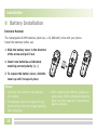
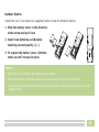
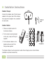
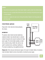
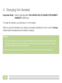
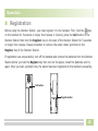
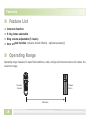
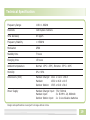
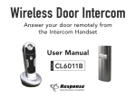
Wireless Door Intercom
Answer your door remotely from
the Intercom Handset
Model:
User Manual
CL6011B
Contents
4
Operation
15
Congratulations
4
Registration
15
Safety Precautions
4
Intercom Communication
16
Unpacking
6
Ringtone Setting
17
Turning the Handset on/off
17
Before you start
Intercom Handset - Layout and
Keys Function
7
Intercom Handset Charger Layout
8
Features
18
Outdoor Station Layout
9
Feature List
18
Operating Range
18
Technical Specifications
19
Installation
10
Battery Installation
10
Installation Instructions
12
Charging the Handset
14
2
Our range of Door Intercom System products include:
CL6011BCS
-
Wireless Door Intercom Charging Dock Station
(accessory to the CL6011 system)
CL3622B
-
Wireless Door Intercom Telephone and Doorbell System
(dual function DECT Telephone and Door Intercom)
CL3622BHSC
-
Wireless Door Intercom Handset and Charger
(accessory to the CL3622 system)
CL3660UM
-
Door Entry System Unlock Module
(compatible with CL3622 and CL6011 systems)
CLOSPSU
-
Unlock Module/Outdoor Station Power Supply Unit
3
Before you start
■ Congratulations
…on purchasing our high quality product. Please read the manual carefully before installing your
system and follow all of the directions to ensure proper installation
■ Safety Precautions
To reduce the risk of electrical shock and injury, please follow these basic safety precautions
before using the phone.
1
Carefully read and observe the instructions in this manual.
2
Follow all warnings marked on the unit.
3
Unplug this product from the wall outlet before cleaning, then use a damp cloth to wipe.
Do not use liquid or aerosol cleaners.
4
Do not place objects on the line cord that may cause damage.
5
Do not use this product in wet surroundings or environments where there is a risk of explosion.
6
Avoid spilling of any liquid on the phone.
4
7
Unplug this product from the wall outlet and refer servicing to qualified service personnel only.
8
Pay attention to the polarity of the batteries, insert the rechargeable batteries in accordance
with polarity symbols (this instruction is found in the installing batteries section).
9
Use only the batteries indicated in the User Manual. Never use other ordinary batteries or
conventional alkaline batteries. Otherwise this may not only cause personal injuries but also
damage to the unit.
10 Do not mix exhausted batteries with full batteries. Exhausted batteries shall not be disposed
of with the usual household waste or in a fire.
11 If the handset will not be used for a long period of time, remove the batteries to prevent
possible leakage.
12 Use only the power supply indicated in the User Manual.
13 Keep the phone out of the reach of children.
14 Use the phone only in the described manner.
15 Stop using the phone if it becomes damaged.
5
■ Unpacking
Once you have unpacked your door Doorbell Intercom System, make sure that all the parts shown
below are available. If any pieces are missing or broken, please promptly call your dealer.
Intercom Handset
Charger
Mains
Adaptor
6
Intercom
Handset
2 x C Cell
Batteries
Outdoor
Station
3 x AAA Ni-MH
Batteries
Nameplate
Labels x 2
User
Manual
Fixing
Kit
■ Intercom Handset - Layout and Keys Function
Visual ringer (orange)
Power indicator (red)
In use indicator (blue)
Earpiece
Carrying clip
Unlock key
Answer key
End key
Down key
Up key
Microphone
Battery
compartment
cover
Charging contacts
7
■ Intercom Handset Charger Layout
Charge pins
Charge
Indicator
Top View
8
Power Jack
Rear View
■ Outdoor Station Layout
Rear View
Speaker
Call button
Registration button
1
2
3
4
Microphone
Front View
Terminal
cover/seal
Battery compartment cover
Terminals
1.
2.
3.
4.
12VDC
12VDC
Unlock
Unlock
Positive input
Negative input
control positive terminal
control negative terminal
Terminals 1 and 2 are used when
connecting optional power supply unit
Terminals 3 and 4 are used when
connecting optional unlock module
9
Installation
■ Battery Installation
Intercom Handset
The rechargeable Ni-MH batteries (AAA size, 1.2V, 800mAh) come with your phone.
Install the batteries before use.
1 Slide the battery cover in the direction
of the arrow and pull it out
2 Insert new batteries as indicated,
matching correct polarity (+, -)
3 To replace the battery cover, slide the
cover up until it snaps in place
Notes:
• Reversing the orientation may damage
the handset.
• The batteries need to be replaced if they
do not recover their full storage capacities
after recharging.
10
• When replacing the batteries, always use
good quality Ni-MH rechargeable batteries.
Never use other batteries or conventional
alkaline batteries.
Outdoor Station
Install the two C size batteries (supplied) before using the Outdoor Station.
1 Slide the battery cover in the direction
of the arrow and pull it out
2 Insert new batteries as indicated,
matching correct polarity (+, -)
3 To replace the battery cover, slide the
cover up until it snaps in place
Notes:
• Reversing the orientation may damage the handset.
• When replacing the batteries, always use good quality C size alkaline batteries.
• If you have installed the batteries, you do not need to connect the DC positive input and
negative input.
11
■ Installation Instructions
Handset Charger
Connect the modular end of the AC power
adapter to the power jack of the charger,
then plug the AC adapter into a standard
AC wall outlet.
To AC wall
outlet
Outdoor Station
1 Choose a suitable location for
the Outdoor Station.
2 Fix the metal mounting bracket
on the wall, using the fixing kit
supplied.
Fixing
Screws
3 Fix the Outdoor Station to the
bracket and secure with the
fixing screws supplied.
The Outdoor Station has the provision to add a Power Supply and an Unlock Module
(available as optional accessories).
12
Fixing Screw
Notes:
• The terminal cover seal on the rear of the Outdoor Station is used to protect the terminal screws.
• Remove the cover to access the terminal screws when connecting the optional power supply
or unlock module.
• Remember to replace the cover prior to fixing the Outdoor Station to the fixing plate with
the fixing screw.
Unlock Module (optional)
Please refer to the instructions that accompany
the module.
IMPORTANT:
The optional unlock module must be installed by a
competent installer. Care should be taken to correctly
connect the polarity when using the optional 12V (max)
power supply. The unlock module operates a contact
with a maximum rating of 240V 10A, which can be
used for automatic locks, switching on lighting etc.
This must be installed by a fully qualified electrician.
Outdoor
Station
Power Supply
Output: +12V
12VDC
GND
Power
PGND
CTRL
SGND
Unlock
Module
Relay
Switch
(10A max)
Please note: When using an external power supply unit to power the Outdoor Station, the batteries
inside the Outdoor Station must be removed before connecting the power supply.
13
■ Charging the Handset
Important Note:
Before initial operation YOU SHOULD FULLY CHARGE THE HANDSET
HANDSET for 15 hours.
To charge the handset, you should place it on the charger.
When you place the handset on the charger, the handset automatically turns on and the Charge
indicator light illuminates while the handset is charging.
Notes:
• The Power indicator (red) on the handset flashes every 30 seconds in the standby mode.
When the voltage is lower than about 3.6V, the Power indicator flashes rapidly, and the
warning tone sounds for every 5 minutes.
• When the voltage is lower than 3.35V, the handset will be turned off automatically.
14
Operation
■ Registration
Before using the Outdoor Station, you must register it to the handset. First, hold the
key
on the handset for 5 seconds or longer then release it. Second, press the Call button of the
Outdoor Station then hold the Register key on the back of the Outdoor Station for 5 seconds
or longer then release. Please remember to remove the small rubber grommet on the
Register key of the Outdoor Station.
If registration was unsuccessfull, turn off the handset and remove the batteries from the Outdoor
Station before you hold the Register key then turn on the power, install the batteries and try
again. Once you hear a prompt tone, the station has been registered to the handset successfully.
Call button
Register button
15
■ Intercom Communication
When a visitor presses the Call Button on the Outdoor Station. A ring tone is heard by the host
and the Visual ringer (orange) flashes. You can lift the handset and press the
key to talk with
the visitor.
Notes:
• The
key can be used to operate the Unlock Module (optional accessory), only after the
conversation starts.
• The conversation can be up to 2 minutes. After 2 minutes, the line will be disconnected
automatically.
• During a conversation if you place the handset on the charger, the line will be disconnected
automatically.
• The ring will continue for one minute if the indoor handset does not respond. Press the
key first, and then press the
key to stop it.
16
■ Ringtone Setting
Ringtone Selection
When the handset is in the standby mode, press the
or
key repeatedly to select the
ringtone (up to 5 types). Press once to play a ring tone, then press again to play the next one,
and so on, until you have selected the ringtone you wish to use. The selected ringtone is stored
automatically.
Ring Volume Adjustment
When the ring is sounding, press the
or
key repeatedly to adjust the ring volume (up to 5
levels). The selected volume is stored automatically.
■ Turning the Handset on/off
After installing the batteries, the handset automatically turns on.
To turn off the handset, press and hold the
key for approximately 5 seconds.
In power off mode, if you want to turn the handset on again, place it on the charger.
17
Features
■ Feature List
• Intercom function
• 5 ring tones selectable
• Ring volume adjustable (5 levels)
• Door unlock function (requires Unlock Module - optional accessory)
■ Operating Range
Operating range measured in open field conditions, walls, ceilings and metal structures will reduce the
maximum range.
Intercom
Handset
Outdoor
Station
150 metres
18
Technical Specification
Frequency Range
1.88 ~ 1.90GHz
Channels
120 Duplex channels
Time Accuracy
0 ± 2ppm
Frequency Stability
< ± 50KHz
Modulation
GFSK
Standby time
7 hours
Charging time
15 hours
Ambient temperature
Normal: 15°C ~ 35°C, Extreme: 35°C ~ 40°C
Humidity
0% ~ 90%
Dimensions (mm)
Handset Charger: 132.1 x 132.1 x 68.5
Handset:
133.0 x 46.0 x 19.5
Outdoor Station: 176.5 x 60.0 x 34.0
Power Supply
Handset Charger input: 7.5V, 300mA
Handset input:
3 x Ni-MH 1.2V, 800mAh
Outdoor Station input: 2 x C size Alkaline batteries
Design and specifications are subject to change without notice.
19
Telephone Helpline:
0845 373 1353
Local Rate Call
Response Electronics Limited, Roman House, Lysons Avenue, Ash Vale, GU12 5QF
www.responseelectronics.com
CL6011B Ed.1