1
35CDi
WALL MOUNTED COMBINATION BOILER FOR CENTRAL HEATING
AND MAINS FED DOMESTIC HOT WATER
INSTALLATION AND
SERVICING INSTRUCTIONS
35CDi
This appliance is for use with Natural Gas or LPG (Cat II 2H3P).
GC NUMBER 47 311 39 (N.G.)
GC NUMBER 47 311 40 (L.P.G.)
CE 97/0086
APPLIANCE OUTPUTS
Minimum
Maximum
Natural Gas
Domestic
Central
Hot Water
Heating
9.0 kW
9.0 kW
35.17 kW
25.0 kW
LPG (Propane)
Domestic
Central
Hot Water
Heating
12.9 kW
12.9 kW
35.17 kW
25.0 kW
IMPORTANT: THESE INSTRUCTIONS APPLY IN THE UK ONLY
AND MUST BE LEFT WITH THE USER OR AT THE GAS METER
Read the instructions before starting work - they have been written to
make the installation easier and prevent hold-ups.
Contents
1.
2.
3.
4.
5.
6.
7.
8.
9.
Installation Regulations .............................................. Page
Introduction.................................................................. Page
Technical Data .............................................................. Page
Siting the Appliance .................................................... Page
Flue Terminal Position ................................................ Page
Air Supply .................................................................... Page
Sealed System .............................................................. Page
Domestic Hot Water .................................................. Page
Gas supply .................................................................... Page
10.
11.
12.
13.
14.
15.
16.
17.
18.
2
2
4
6
6
7
7
8
8
Electrical........................................................................ Page 8
Installation.................................................................... Page 13
Commissioning ............................................................ Page 17
User information.......................................................... Page 19
Inspection and Servicing ............................................ Page 19
Replacement of Parts .................................................. Page 20
Short Parts List ............................................................ Page 26
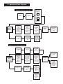
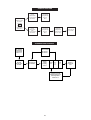
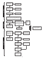
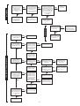
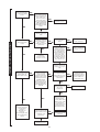
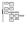
Operational Flow Diagrams........................................ Page 27
Fault Finding ................................................................ Page 29
1. Installation Regulations
2. Introduction
1.1 Gas Safety (Installation & Use) Regulations 1994 (Amended
1996) : It is the law that all gas appliances are installed by a
competent person in accordance with the above regulations. Failure
to install appliances correctly could lead to prosecution. It is in your
interest, and that of safety, to ensure compliance with the law.
1.2 The manufacturers notes must not be taken, in any way, as
overriding statutory obligations.
1.3 The compliance with a British Standard or European Norm
does not, of itself, confer immunity from legal obligations.
1.4 The installation of the appliance must be in accordance with
the relevant requirements of the Gas Safety Regulations, current
IEE Regulations, Building Regulations, Building Standards
(Scotland) and local water bye-laws.
1.5 The installation should follow the recommendations of the
following British Standards unless otherwise indicated:
BS6798 - Specification for the installation of gas fired hot water
boilers of rated input not exceeding 60kW (Gross).
BS5449 - Central heating for domestic premises.
BS5546:1 - Installation of gas hot water supplies for domestic purposes.
BS5440:1 - Flues and ventilation for gas appliances of rated input
not exceeding 60kW (Gross): Flues.
BS5440:2 - Flues and ventilation for gas appliances of rated input
not greater than 60kW (Gross): Air supply.
BS 5482 - Domestic butane and propane gas burning installations permanent dwellings.
BS6891 - Installation of low pressure gas pipework installations
upto 28mm (R1).
BS6700 - Domestic water supply in buildings.
BS7593 - Water treatment in domestic heating systems.
1.6. To ensure that the installation will perform to the highest
standards, the system and components should conform to any
other relevant standards.
1.7. The appliance and/or components conform, where
applicable, with the Essential Requirements of the Gas Appliance
Directive, the Boiler Efficiency Directive, the EMC Directive and the
Low Voltage Directive.
1.8. In accordance with the requirements of COSSH the appliance
does not contain any substances which are harmful to health.
1.9. Product Liability regulations indicate that, in certain
circumstances, the installer can be held responsible, not only for
mistakes on his part but also for damage resulting from the use of
faulty materials. We advise that, to avoid any risk, only quality
approved branded fittings are used.
1.10. LPG Installation. The appliance shall not be installed in a
room or internal space below ground level when it is intended for
use with LPG. This does not preclude the installation into rooms
which are basements with respect to one side of the building but
open to the ground on the opposite side.
1.11. The advice and instructions given in this document covers, as
far as possible, the forseeable situations which may arise. Contact
Worcester Heat Systems Technical Department, Telephone: 0990
266241, for advice on specific installations.
The Benchmark initiative is the new code of practice to
encourage the correct installation, commissioning and servicing
of domestic central heating boilers and system equipment.
The 'Log-book' is a vital document that must be completed
by the installer at the time of installation. It confirms that the
boiler has been installed and commissioned according to the
manufacturers instructions.
Without the completion of the Log-book, manufacturers may
refuse to respond to a call-out from a householder, who will be
advised that he or she must call back the installer, who has not
fulfilled his obligations to record the information required by the
initiative.
It is important that:
The services and the system are properly flushed as specified.
The User is clearly instructed on the correct operation of the
appliance.
The benefits of regular servicing are explained - to maintain the
efficiency and extend the life of the appliance.
2.1. General Information
2.1.1. The appliance is set to give a maximum output of
35.17kW to the domestic hot water and 25kW to the heating
system. The hot water flow rate is limited to a nominal 12.6
l/min at a maximum temperature rise of 40°C.
2.1.2. The sanitary water section of the
3 appliance is suitable for
water mains
pressures of upto 10bar.
3
2.1.3. Conversion kits are available to convert the appliance from
Natural Gas to Propane operation and vice versa. The kits include
conversion instructions.
2.2 Electrical Supply
2.2.1. 230V ~ 50Hz. Load 180 watts. External fuse 3A, Internal
fuses F1 - 2A, F2 - 1.25A (20mm).
2.3 Gas Supply
2.3.1. The appliance requires 4.12m /h of natural gas (G20) or
1.64m /h of propane (G31).
2.3.2. The meter or regulator should deliver 20mbar (G20) or
37mbar (G31) at the appliance, which is equivalent to about
18.5mbar or 35.5mbar at the gas valve inlet pressure test point.
2.4 Installation
2.4.1. The appliance is suitable for indoor installation only.
2.4.2. The appliance is for use with a sealed system only.
2.4.3. The clearances specified for servicing must not be reduced.
2.4.4. Do not place anything on top of the appliance .
2.4.5. It is a room sealed appliance and a separate combustion
air supply is not required in any room or compartment in which
the appliance is fitted.
2.4.6. If the appliance is fitted in a cupboard or a compartment is
built around it after installation, then the structure must conform
with the requirements of BS6798. However, because of the low
casing losses, there is no need for the cooling ventilation
openings in the compartment. The spaces specified for servicing
must be maintained.
2.4.7. There is space for the service pipes to pass at the back of
the appliance.
2
2.5 Flue
2.5.1. The flue can be to the right, left or rear.
2.5.2. The flue terminal, on the outside wall, must not be
obstructed or damaged.
2.5.3. A terminal guard, Type K2 - GC 393 553, is available from
Tower Flue Components, Vale Rise, Tonbridge TN9 1TB
2.5.4. An internal flue fitting kit is available. Fitting instructions
are given in Section 11.9.
2. 6. Controls
2.6.1. Control knob for switching the appliance On or Off.
2.6.2. Control knobs for adjusting the CH or DHW temperatures.
2.6.3. CH control knob switches the CH off and on.
2.6.4. A programmable room thermostat or a facia mounted
programmer or clock is available.
2.6.5. A radio frequency room thermostat is available.
2.6.6. A mains voltage room thermostat and/or an externally mounted
mains voltage programmer may be connected to the appliance.
2.7. System
2.7.1.
All dirt must be flushed from the system before
connecting the appliance.
2.7.2. The connections in the system must withstand a pressure
of upto 3bar.
2.7.3. Radiator valves must conform to BS2767:10:1977.
2.7.4. Table 3 gives the pump head available for the system and
the required temperature differential.
2.7.5. A drain cock must be fitted to the lowest point of the system.
2.7.6. An air vent should be fitted to the highest point of the system.
2.8. Showers, Bidets, Taps and Mixing Valves
2.8.1. All taps and mixing valves must be suitable for the
available mains pressure and temperatures upto 65°C. It may be
necessary to fit a pressure reducing valve.
2.8.2. Hot and cold mains fed water can be supplied to overrim
bidets but is subject to local water company requirements.
2.8.3. The flow of water from individual outlets varies on all
mains fed systems that are not fitted with flow balancing valves.
2.8.4. If a pressure equalising valve is fitted then the domestic
hot water temperature should be set to maximum.
2.8.5. Thermostatically controlled shower valves give extra
comfort and protection.
2.9. Safety
2.9.1. The appliance must not be operated with the inner casing
cover removed.
2.9.2. The gas and electricity supplies must be turned off before
servicing or working on the appliance.
2.9.3. Temperature monitoring controls are fitted to prevent overheating.
2.9.4. Automatic frost protection is provided which will protect
the appliance when no heat demand is present.
2.9.5. Automatic pump seizure protection is provided.
2.9.6. The gas valve solenoids are successively and alternately closed
to check for gas tightness by reference to the flame cut-off time.
2.10. Operation
2.10.1. Central Heating:
A demand for heat will ignite the burner and it will operate at
minimum pressure for 2 minutes before increasing to the maximum
over a period of 1 minute and then automatically match the system
requirements. At the end of the demand the burner will go out and
the pump will continue to run for upto 4 minutes or the fan for 15
seconds. There is an anti-cycle time of 3 minutes.
2.10.2. Domestic Hot Water:
A demand for hot water will light the burner with the pressure
rising to maximum over a period of 4 seconds. At the end of the
demand the fan will continue to run for 15 seconds if neither
pump is operating. There is an anti-cycle time of 10 seconds.
The demand for hot water will override the CH function for the
period of the hot water demand. In winter when the inlet water
temperature is very low it will be necessary to reduce the flow at
the taps to maintain the delivery temperature.
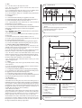
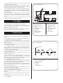
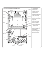
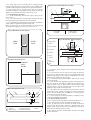
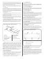
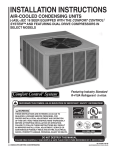
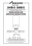
Fig. 1. Facia Controls
0
MAX.
2
1
MIN.
MAX.
4
3
5
1. Mains ON/OFF Control Knob
2. Central Heating Temperature Control Knob and CH ON/OFF
Control
3. Domestic Hot Water Temperature Control Knob
4. Programmer/Clock Position - (Optional)
5. System Pressure Gauge
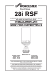
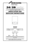
Fig. 2. Water Flow Diagram
10
1
2
3
4
5
6
9
8
7
A
3
B
C
D
1. Primary Heat Exchanger
2. Sealed System Expansion
Vessel
3. Central Heating Pump
4. Domestic Hot Water
Pump
5. Relief Valve
6. Bypass Adjuster
7. Water Flow Regulator
8. Flow Switch
9. Domestic Hot Water Heat
Exchanger
10. Primary Flow Manifold
A. Domestic Hot Water Flow
B. Cold Water In
C. Central Heating Flow
D. Central Heating Return
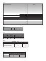
3. Technical Data
Table 1.
kW
9.0
25.0
35.17
Btu/h
30,700
85,300
120,000
NOMINAL BOILER RATINGS (10 Minutes After Lighting)
BOILER ADJUSTED FOR G20 (Natural Gas)
BURNER SETTING
INPUT (Net)
PRESSURE
kW
Btu/h
m bar.
in. wg.
11.42
38,900
1.5
0.6
28.52
97,300
8.3
3.3
39.61
135,100
14.2
5.8
12.9
25.0
35.17
44,000
85,300
120,000
16.5
29.14
40.5
OUTPUT
GAS RATE
3
m /h
1.19
2.97
4.12
ft3/h
41.98
104.8
145.5
BOILER ADJUSTED FOR G31 (Propane)
56,300
6.0
99,400
19.0
138,200
34.7
0.68
1.23
1.64
24.0
43.3
57.9
Natural Gas: Net Input = Gross Input x 0.901
2.4
7.6
13.9
LPG (Propane): Net Input = Gross Input x 0.922
Table 2.
FLUE DETAILS
HORIZONTAL FLUE TYPE C12
WALL HOLE DIAMETER
STANDARD FLUE
EXTENDED FLUE
mm
inches
EXTERNAL FIX
125
5.0
INTERNAL FIX
150
6.0
MINIMUM LENGTH
100
4.0
MAXIMUM LENGTH
1000
39.3
MAXIMUM LENGTH
2000
78.7
110
4.3
FLUE ASSEMBLY DIAMETER
Table 3
PUMP HEAD
BOILER OUTPUT
HEAD
MIN. FLOW RATE
FLOW/ RETURN
DIFFERENTIAL
°C
°F
kW
Btu/h
Metres
Feet
L/min.
Gal/Min.
9.0
30,700
4.2
13.6
11.7
2.57
11°C
20°F
25.0
85,300
2.08
21.57
4.75
16.5°C
30°F
6.67
Table 4
MECHANICAL SPECIFICATIONS
CENTRAL HEATING FLOW - COMPRESSION
22mm
CENTRAL HEATING RETURN - COMPRESSION
22mm
COLD WATER INLET - COMPRESSION
15mm
DOMESTIC HOT WATER FLOW - COMPRESSION
15mm
GAS INLET
Rc 3⁄4
RELIEF VALVE DISCHARGE - COMPRESSION
15mm
CASING HEIGHT
900mm
CASING WIDTH
500mm
CASING DEPTH
310mm
WEIGHT - DRY
52kg
WEIGHT - MAXIMUM INSTALLATION
49kg
WEIGHT - PACKAGED
56kg
4
Table 5
PERFORMANCE SPECIFICATIONS
PRIMARY WATER CAPACITY
3.0 litres
MAXIMUM MAINS INLET PRESSURE
10 bar
MINIMUM MAINS INLET PRESSURE (working) for max. hot water flow
1.3 bar
MINIMUM MAINS INLET PRESSURE (working) to operate appliance
0.8 bar
MAXIMUM CENTRAL HEATING FLOW TEMPERATURE
82°C nom
MAXIMUM CENTRAL HEATING SYSTEM SET PRESSURE
1.5 bar
MINIMUM CENTRAL HEATING SYSTEM PRESSURE
0.45 bar
DOMESTIC HOT WATER TEMPERATURE RANGE
50 - 62°C
OUTPUT TO DOMESTIC HOT WATER
OUTPUT TO CENTRAL HEATING
NATURAL GAS (G20)
9.0 - 35.17 kw
LPG - PROPANE (G31)
12.9 - 35.17 kw
NATURAL GAS (G20)
9.0 - 25.0 kw
LPG - PROPANE (G31)
12.9 - 25.0 kw
DOMESTIC HOT WATER SPECIFIC RATE AT 35° RISE
16.7 l/min
MAXIMUM DOMESTIC HOT WATER FLOW RATE FROM APPLIANCE AT 40° RISE
NOx CLASSIFICATION
Class 3
MAXIMUM FLUE GAS MASS FLOW RATE
129.5 kg/h
SEDBUK NUMBER
78.9%
SEDBUK BAND
D
Table 6
DOMESTIC HOT WATER - TEMPERATURE RISE
DISCHARGE RATE l/min
10
11
12
TEMPERATURE RISE °C
50
45.5
41.5
13
38.5
Table 7
GAS SUPPLY SYSTEM - BASED ON NG (G20)
TOTAL LENGTH OF GAS SUPPLY PIPE meters
3
6
9
GAS DISCHARGE RATE m3/h
PIPE DIAMETER mm
8.7
5.8
4.6
22
18.0
12.0
9.4
28
Table 8
CLEARANCES
(mm)
INSTALLATION
ABOVE APPLIANCE
35
IN FRONT OF APPLIANCE
600
BENEATH APPLIANCE
200
RIGHT AND LEFT HAND SIDE
25
SERVICE
35
600
200
5*
* If a Side Flue Connection is made then this service clearance must be 25mm at that side.
Table 9
INITIAL
PRESSURE bar
1.0
1.5
12.6 l/min ±15%
SYSTEM CAPACITY
TOTAL SYSTEM VOLUME litres
INITIAL CHARGE PRESSURE bar
0.5
1.0
1.5
72
92
39
53
64
5
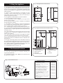
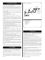
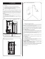
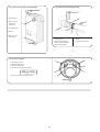
Fig. 3. Casing Dimension and Clearances
4. Siting the Appliance
35
4.1. The appliance may be installed in any room but refer to the
requirements of the current IEE regulations and, in Scotland, the
relevant electrical provisions of the Building Regulations with
respect to the installation of appliances in rooms containing
baths or showers.
4.2. Where a room sealed appliance is installed in a room
containing a bath or shower, any switch or appliance control
using mains electricity must not be able to be touched by a
person using the bath or shower.
4.3. The appliance is NOT suitable for external installation
4.4. No special wall protection is required.
4.5. The wall must be able to support the weight of the
appliance. Refer to Table 4.
4.6. The specified clearances must be available for installation
and servicing. Refer to Table 8.
4.7. The appliance can be installed in a cupboard/compartment
to be used for airing clothes providing that the requirements of
BS6798 and BS5440/2 are followed. Refer to Section 2.4.6.
4.7.1. The airing space must be separated from the boiler space
by a perforated non-combustible partition. Expanded metal or
rigid wire mesh is acceptable provided that the major dimension
is less than 13mm.
4.7.2. The requirements for servicing space must be met when
an appliance is in a cupboard or compartment used for airing
clothes. Refer to Table 8.
4.7.3. The clearance between the front of the appliance and the
cupboard/compartment door should be not less than 75mm.
4.7.4. If the installed boiler is to be enclosed then the
requirements of BS6798 and BS5440:2 must be followed. Refer
to Section 2.4.6.
4.8. The pipe connection positions on the manifold are shown in
Fig. 4 and on wall template allowing the system to be pre-piped
and flushed before the appliance is fitted. Refer to Section 2.4.6.
4.8.1. Always consider the possibility that the pipes may need
to be separated from the appliance after installation.
4.9. LPG Installation. Refer to Section 1.10.
500
310
900
Installation
25
5 or 25
Service
600
200
Fig. 4. Pipework Connections and Flue Position
130
250
160
310
500
A
B
C
D
E
F
G
H
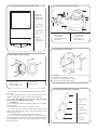
5. Flue Terminal Positions
A.
B.
C.
D.
E.
5.1. The flue system must be installed following the
requirements of BS5440:1.
5.2. Standard flue length is 100 - 1000mm. An extension kit for
flues upto 2m is available.
Fig. 5. Flue Terminal Positions
322
252
235
206
203
144
98
55
Relief Valve Drain
Central Heating Return
Bypass Adjuster
Drain Point
Central Heating Flow
20
F. Cold Water In
G. Domestic Hot Water
Flow
H. Gas Inlet
TERMINAL POSITION
A– Directly below an openable window or
other opening e.g. air brick.
B– Below gutters, soil pipes or drain pipes.
C– Below eaves.
D– Below balconies or car port roof.
E– From vertical drain pipes and soil pipes.
F– From internal or external corners.
G– Above ground, roof or balcony level.
H– From a surface facing a terminal.
I– From a terminal facing a terminal
J– From an opening in a car port (e.g. door
window) into dwelling.
K– Vertically from a terminal on the same
wall.
L– Horizontally from a terminal on the same
wall.
M– From door, window or air vent (achieve
where possible).
6
MIN. DISTANCE
300 mm (12 in.)
75 mm (3 in.)
200 mm (8 in.)
200 mm (8 in.)
75 mm (3 in.)
300 mm (12 in.)
300 mm (12 in.)
600 mm (24 in.)
1200 mm (47 in.)
1200 mm (47 in.)
1500 mm (59 in.)
300 mm (12 in.)
150 mm (6 in.)
5.3. The terminal must not cause an obstruction nor the
combustion products a nuisance.
5.4. Under some climatic conditions the terminal might steam.
Positions where this might be a nuisance should be avoided.
Combustion products must not enter the roof space.
5.5. If the terminal is within 1m of a plastic or painted gutter or
within 500mm of painted eaves then an aluminium shield at
least 750mm long should be fitted to the underside of the gutter
or painted surface.
5.6. If the terminal is less than 2m above a surface to which
people have access then a guard must be fitted. The guard must
be evenly spaced about the terminal and fixed with plated
screws.
5.7. A guard, Type K2, can be obtained from Tower Flue
Components, Vale Rise, Tonbridge, TN9 1TB.
Fig 6 - Sealed system
1
2
13
Static Head
of System
12
11
DHW
Cold Water
7
8
A Drain Cock Should be Fitted at the
Lowest Point of the System
3
4
5
6
10
9
6. Air Supply
1. Make-up Bottle
2. Non-return Valve
3. Domestic Hot Water
Pump
4. Central Heating Pump
6. Relief Valve
7. Drain Tap
8. Bypass Adjuster
9. Water Main
6.1. A separate vent for combustion air is not required.
6.2. If the appliance is in a cupboard or compartment then,
because of the low casing losses, it is not necessary to have
additional ventilation for the boiler.
6.2.1. There must be proper clearance around the appliance to
allow the free movement of the air. Refer to Table 8.
7. Sealed System
7.1. The system must comply with requirements of BS6798 and
BS5449.
7.2. The appliance must not be operated without the system
being full of water and correctly pressurised.
7.3. The pressure relief valve will operate at 3 bar. The discharge
pipe must be directed away from any electrics and from where it
might be a hazard.
7.4. The pressure gauge shows the required system pressure and
the actual system pressure.
7.5. The expansion vessel, to BS4814, has a capacity of 10 litres
charged to 0.5 bar, which is suitable for a static head of 5 metres.
A schraider type valve allows the pressure to be increased if the
static head is greater than 5 metres.
7.5.1. If the expansion vessel fails then it must be replaced with
the designated spare part.
7.6. Refer to BS 7074:1, BS5449 and Table 9 for a guide to the
available system capacity.
7.7. The maximum system design pressure is 1.5 bar. If the
pressure is above 2.6 bar when the appliance is at maximum
temperature then another expansion vessel must be fitted as
near to the appliance as possible in the return pipe.
7.8. The filling point must be at a low level.
7.8.1. Water lost from the system must be replaced. The makeup connection must be close to the appliance in the heating
return pipe through an approved non-return valve.
7.8.2. The system and the appliance must be properly vented.
Repeated venting loses water from the system and usually
indicates that there is a leak.
7.8.3. The connection to the mains water supply must have the
approval of the local water company.
7.9. The integral by-pass should be adjusted to balance the
system when commissioning the appliance.
7.10. The CH pump is set at maximum and must not be
adjusted.
7.11. All connections in the system must withstand a pressure of
up to 3 bar.
7.12. The radiator valves must conform to BS2767:10 and other
valves to BS1010.
Lock
Shield
Valve
Radiator
Valve
10. BS Stop Valve
11. Domestic Hot Water
Flow Regulator and
Switch
12. Domestic Hot Water
Expansion Vessel
(Optional)
13. Auto Air Vent
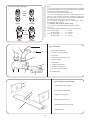
Fig 7 - System Fill
1
4
2
2
3
5
1.Central Heating Return
2.Non-return Valve
3.Test Cock
5.Stop Cock
6.Temporary Hose
7
8. Domestic Hot Water
Fig 8 - System Make Up
8.1. If necessary reference should be made to the local water
company before connecting the appliance.
8.2. Devices which would prevent the flow of expansion water
must not be fitted unless separate arrangements have been
made. A mini-expansion vessel can be fitted within the casing if
necessary. A thread sealant suitable for potable water must be
used.
8.3. The last 600mm of mains water pipe before the appliance
must be in copper.
8.4. The domestic hot water circuit of the appliance is suitable
for a mains pressure of upto 10 bar. A pressure reducing valve
must be fitted if necessary.
8.5. A mains supply isolating valve is fitted.
8.6. The DHW pump is set at maximum and must not be
adjusted.
8.7. The maximum hot water flow rate is set at the factory to
12.6 (±15%) l/min giving a nominal temperature rise of 40°C
with the temperature control at maximum. This rate is
equivalent to a specific rate of 16.7 l/min at a rise of 35°C . Refer
to Table 6.
8.8. The temperature rise, upto the maximum set by the user, is
automatically maintained by the modulation of the heat input.
8.9. In winter, when the mains water temperature is very low, the
water flow, adjusted at the tap or shower, should be reduced to
maintain the required delivery temperature.
8.10. It is suggested that long pipe runs to taps or showers be
insulated to prevent the rapid cooling of the water.
8.11. Hot and cold taps and mixing valves must be suitable for
the available mains pressure. If necessary a pressure reducing
valve should be fitted.
8.12. No anti-syphonage arrangements are necessary for fixed
head showers.
8.13. The hose of a loose head shower must be fixed so that the
shower head cannot get closer than 25mm to the top edge of the
bath to prevent immersion in the water. Alternatively the shower
can be fitted with an anti-syphonage device at the flexible hose
connection.
8.14. Thermostatically controlled shower valves will give extra
comfort and guard against extreme temperatures.
8.15. Hot and cold mains water direct to a bidet is, subject to the
approval of the local water company, permissible provided that
the bidet is of the overrim flushing type. The outlets must be
shrouded and unable to be fitted with a hand-held spray. No antisyphonage arrangements are needed.
8.16. The maximum temperature of the heat exchanger is
limited and there is normally no need for water treatment to
prevent scale formation.
8.17. If the water hardness is very high then an anti-scaling
device can be considered. Further information is available from
WHS Technical Information Department, Telephone 0990
266241.
8.18. The installation of a scale inhibitor must be strictly in
accordance with the requirements of the local water company.
4
2
1
3
6
300mm Above
the Highest Point
of
the System
5
1. Central Heating Return
2. Auto Air Vent
3. Non-return Valve
4. Make-up Vessel
5. Stop Cock
6. Fill Point
10. Electrical
10.1. Mains supply : 230V ~ 50Hz, 180watts. External fuse 3A,
Internal fuses F1 - 2A, F2 - 1.25A (20mm). Spare internal fuses
are supplied with the appliance. Refer to Fig 15.
10.2. The appliance must be earthed.
It must be possible to completely isolate the appliance.
10.3. The mains cable must be 0.75mm2 (24x0.20 mm) to
BS6500-Table 15 or 16.
10.4 The mains cable must be connected to the terminal ST12
marked L (red or brown lead), N (black or blue lead ) and the
Earth stud (green or green/yellow lead) and secured with the
cable clamp. Check that sufficient loose lead has been left to
allow access to the control box. The Earth lead must be still be
slack when the other leads are taut. Refer to Fig 9.
10.5. The connection to the mains must be either: A 3A fused
three-pin plug and unswitched socket outlet, (both complying
with BS1363) or a double pole isolator with a contact separation
of 3mm in all poles and supplying the appliance and controls
only.
10.6. Access to the mains connection on the driver board is
gained by removing the bottom cover from the facia.
Refer to Fig 11.
10.7. A room thermostat or an externally mounted programmer
must be suitable for mains voltage operation and the leads
securely fixed in the clamps provided. The controls must be
earthed at the bracket by the control board. Refer to Fig 10
and 12.
10.8. A programmer, to fit into the facia, is available to control
the CH. Full instructions are sent with the programmer. Refer to
Fig 16.
10.9. A clock, to fit into the facia, is available to control the
operation of the appliance.
9. Gas Supply
9.1. The appliance requires 4.12 m 3/h of natural gas (G20) or
1.64 m 3/h of propane (G31). Check that the supply system can
accommodate this together with any other appliances
connected to it. Refer to Table 7.
9.2. A natural gas appliance must be connected to a governed
meter.
9.3. There must be a pressure of 20mbar (G20) or 37mbar (G31)
at the inlet to the appliance. This is equivalent to a pressure of
18.5 - 19.0mbar (G20) or 35 - 35.5mbar (G31) at the inlet to the
gas valve.
8
10.10. On very rare occasions an external frost thermostat might
be considered where parts of the system are remote from the
appliance. Refer to Worcester Heat Systems Technical
Department for more information - Tel: 0990 266241.
10.11. A radio frequency room thermostat is available for use
with the appliance.
10.12. Safety check: If there is an electrical fault after installation
check for fuse failure, short circuits, incorrect polarity of
connections, earth continuity or resistance to earth.
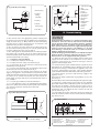
Fig 9 - Mains Electrical Connection
230V L
N
Ns Ls LR
Fig 11 - Facia Connections Cover
ST12
1
Brown
2
Blue
Strain relief clamp
Green/Yellow
3
1. Control Panel Fixing Screws
2. Facia
3. Control Panel Pivot Point
4. Connection Cover
5. Connection Cover Fixing
Screws
Fig 10 - Electrical Connections
5
4
10
9
Ns Ls LR Spare
Motor
Ne
ut
ral
e
Liv
9
ST8
d
he
itc
Sw
9. Fuse-F2
10. Cable Entry Clamp
11. ST13-24volt Controls
(not used)
12. Main Harness and Clamp
13. Control Panel Pivot
Point
e
Liv
230 V room thermostat and
Programmer Connections
1
1. ST12-Mains
2. Fuse-F1
3. Earth Screw
4. ST8-Room Thermostat
and External Control
-Mains Voltage
5. Cable Entry Screw Clamp
6. Earth Tag
7. ST15-Pump
8. ST1-Fan
Ns Ls LR
Spare
Motor
Switched Live
Live
ST8
Neutral
230 V Programmer Connections
Switched Live
12
Swit
ched
Live
4
7
Live
2
6
Remove Link
Neutral
3
11
8
5
Spare
ST8
Live
13
Ns Ls LR
Neutral
230 V Room Thermostat Connections
Fig 12 - Mains Voltage External Controls Connections
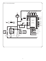
Fig 13 - Pictorial Wiring Diagram
2 Orange
2 Red
14
Black
Red
White
13
1. Spark Generator
12
2. 6 Way In-Line Connector
6 Wires
from
Bottom
of
Boiler
Green
15
Green
3. 2 Way In-Line Connector
4. Gas Valve
5. Flow Switch
6. DHW Sensor
7
7. Spark Electrode
8
8. Sense Electrode
Blue
9. CH Pump
10. DHW Pump
4
11. Pump Relay PCB
Violet
Grey
Yellow
Brown
9
6
10
w
llo
Ye ack
Bl ck
a
Bl
12. CH Sensor
13. Fan
1
14. Overheat Cut-Off Thermostat
5
3
To Flow
Switch
2 Pink
2 Orange
2 Green
2 Red
2
White
11
ST23
ST15
ST1
Pink
ST12
LINK
White
Black
White
Red
Blue
Brown
ST8
Blue
Brown
6 Grouped
Wires
to Top of
Boiler
From
Connection
Black
15. Air Pressure Switch
Brown
Blue
Gr/Yellow
Gray
MAINS
IN
Green/Yellow
Blue
Brown
Fig 16 - Programmer Connection
Fig 15 - Replacement Fuses
1
6
5
2
4
3
3
1
4
2
5
1. Control Panel Pivot
Point
2. Fuses-F1,F2
3. Pressure Gauge
1. Programmer
2. Programmer
Fixing Clip
3. Pressure
Gauge
4. Facia Panel
5. Control Board
Assembly
10
4. Programmer
Connector
5. Facia
6. Control
Board
Fig 14 - Functional Wiring Diagram
CH
Demand
Indicator
Spark
Electrodes
DHW
Demand
Indicator
N
Flame
Detect
Indicator
Mains
Indicator
Red
Red
Red
Green
Electronics
Spark
Indicators
Fuse F2
(1.25A Slow)
Regulator Valve
Inputs
Main Valve
Main Valve
Pump Control
Board
Transformer
Fuse F1
(2A Slow)
Convert AC to low
voltage electrics
LIVE
IN
ST8
(Ns)
Room
Thermostat
On/Off
Switch
ST 12 Pin N
ST8
(Ls)
Flow Switch
CH Sensor
Electronics/
microprocessor
(Safety Low Voltage)
DWH Sensor
Air Pressure
Switch
Flame Sense
Over-Heat
Cut Off
24V Programmer
Outputs
ST 12 Pin L
MAIN CONTROL
BOARD
ST8
(Lr)
Settings
ST 23
Brown
X1
Pin 1
X2
Pin 1
Optional Link
From Main
Control Board
Grey
DHW Control Knob
Relay
REL 1
REL 4
REL 3
CH Control Knob
Electronics
Electronics
ST 15
Pin L
X3
Pin 1
Brown
Brown
CH
Pump
ST1
Centre
Pin
DWH
Pump
PUMP
CONTROL
BOARD
White LOW
HIGH
Electronics
Red
ST 1
Pin L
CH pressure adjust pot
Gas Valve Mode
Switch
Reset Button
Fan
(2 speed)
N
11
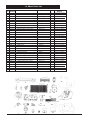
Fig 17- Front View of Appliance (control panel removed)
3
28-Fig 55
1-Fig 22
4-Fig 57
2-Fig 23
27-Fig 55
5-Fig 61
26-Fig 42
6-Fig 42
25-Fig 36
7-Fig 57
8
24-Fig 43
9-Fig 44
10-Fig 45
23-Fig 59
22-Fig 56
21-Fig 46
11-Fig 38
20-Fig 40
12-Fig 38
13-Fig 27
19-Fig 49
18-Fig 49
14-Fig 27
15-Fig 41
17-Fig 27
16-Fig 41,27
12
1. Fan & Flow Sensor
2. Fan Connections
3. Combustion Products
Test Point
4. Overheat Thermostat
5. Air Pressure Switch
6. Flue Hood
7. Overheat Thermostat Phial
8. Combustion Chamber Cover
9. Flame Sense Electrode
10. Burner
11. Central Heating Pump
12. Domestic Hot Water Pump
13. Pressure Gauge Connection
14. Relief Valve
15. Bypass Adjuster
16. Drain Point
17. Flow/Return Manifold
18. Domestic Hot Water
Expansion Vessel
Connection (optional)
19. Domestic Hot water Flow
Control Assembly
20. Gas Valve
21. Modulator Pressure Adjuster
22. Domestic Hot Water Sensor
23. Domestic Hot Water Heat
Exchanger
24. Spark Electrode
25. Primary Flow Manifold
26. Flue Hood Fixing
27. Auto Air Vent
28. Primary (CH) Sensor)
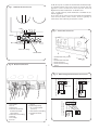
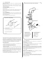
Fig 19- Side Flue Opening Position
11. Installation
160
11.1. General.
11.1.1. The appliance is suitable for sealed systems only.
11.1.2. The flue must be installed in accordance with BS5440:1.
11.2. Unpacking and appliance preparation
11.2.1. Remove the appliance from its packing and lay it on its
back.
11.2.2. Unscrew the connections linking the appliance to the wall
mounting plate/manifold assembly and separate the two
assemblies by lifting the base of the appliance and pulling the
mounting plate/manifold assembly out from beneath the
appliance.
11.3. Site preparation
11.3.1. Check that the wall is sound, flat and will support the
weight of the appliance. Refer to Table 4.
11.3.2 Check that the correct position for the appliance has been
chosen.
SIDE
FLUE
OPENING
CE
IAN ON
L
P
I
AP OSIT
P
Fig 18- Wall Mounting Plate and Manifold Assembly
462
420
210
Fixing Holes (6)
Top of Cabinet
180
11.4. Fixing holes and flue opening
11.4.1. Fix the template or the mounting plate/manifold
assembly to the wall and mark the position of the fixing holes
and the flue duct opening. Refer to Fig 18 and 19.
11.4.2. Check the position and alignment of the marks before
drilling the fixing holes and the flue opening. Note: If a rear flue
is to be used stick the foam gasket, supplied in the installation
pack, onto the wall.
11.5. Wall mounting plate and manifold
11.5.1. If the flue is to be fitted from inside the room then it must
be fitted through the wall before the wall mounting plate
assembly is fitted to the wall. Refer to Section 11.8-9.
11.5.2. Fit the plugs and fix the plate/manifold assembly to the
wall.
11.5.3. Check that the assembly is properly aligned before
tightening the screws.
11.5.4. Notches on the manifold indicate the centrelines of the
pipe connections.
11.6. Gas and water pipes
11.6.1. Remove the gas cock, fix the appropriate fitting to
connect the inlet pipe and replace. Refer to Fig 4.
11.6.2. Pre-plumbing is not advised if no movement in the
pipework is available.
Mounting Plate
114
Wall Hole
125 Internal Fix
150 External Fix
773
322
A
252
B
202
C
144
D 98
E 55
F
683
904
72
A. Relief Valve Discharge
B. Central Heating Return
C. Central Heating Flow
D. Cold Water Inlet
E. Domestic Hot Water Flow
F. Gas Inlet
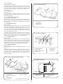
Fig 20- Rear Pipe Work Clearance
462
420
210
Before the appliance is fitted to the wall thoroughly
flush the system and mains water supply.
11.6.3. If it is necessary for any of the pipes to run up the back of
the appliance then they must be arranged to pass either side of
the flue duct outlet when a rear flue system is used.
Refer to Fig 20.
Mounting Plate
114
75
75
Space
for
pipes
Space
for
pipes
175
175
13
Fig 21-Casing and Control Panel Fixing Screws
Fig 22- Fan and Air Flow Sensor Fixing
- Negative
2. Inner Casing
Fixing Screws
(4)
2
5
1
4
8
+
2
+Positive
4
3
3. Control Panel
Fixing Screws
(2)
1. Electrical connections
2. Fan Assembly
Fixing Screw
3. Fan Mounting Plate
4. Fan Casing
4. Controls
Connection
Fixing Screws
(3)
3
1
7
-
1.Transport
Bracket and
Bottom Panel
Fixing Screws
(2)
6
5. Air Flow Sensor
6. Flue Duct Clamp
7. Air Flow Sensor
Fixing Screw
8. Flue Sample Tube
1
Fig 23-Fan Motor Connections
1
Fig 24-Air Duct Clamp Assembly
1
2
2
3
5
4
3
1. Fan Motor
2. Connector - Neutral Black - 6.3mm
3. Connector - Low Speed White - 4.8mm
4. Connector - High Speed Red - 2.8mm
4
1. Air Duct - Inner
2. Cabinet Casing
3. Air Duct Clamp - Outer
4. Seal - Silicone
5. Fixing Screws (3)
Fig 25-Cabinet Blanking Plate Assembly
11.6.4. Pipework can only run horizontally outside the limits of
the casing.
11.6.5. It is important that the pipes are not fixed near the
appliance using clips that put a strain on the connections.
11.6.6. Before the appliance is fitted to the wall thoroughly
flush the system and mains water supply.
11.7. Install Boiler
11.7.1. Remove the cabinet front panel by lifting off the bottom
and pulling away.
11.7.2. Remove the inner casing cover. Refer to Fig 21.
11.7.3. Pull off the tubes from the air flow detector and the flue
sample tube. Carefully pull off the electrical connections at the
fan. Refer to Fig 22,23.
11.7.4. Unscrew and remove the fan from the flue hood.
11.7.5. Fit the air duct clamp assembly to the appropriate exit
from the appliance. Do not, at this stage, tighten the screws. Seal
the unused openings using the cabinet blanking plate assembly.
Refer to Fig 24,25.
1
2
1. Outer Sealing
Plate
2. Boiler Casing
14
3
3. Adhesive
Sealing Gasket
4
4. Inner Sealing
Plate
5
5. Nuts and
Washers
11.7.6. Check that the gas and water valves are closed. Refer to
Fig 26.
11.7.7. Lift the appliance onto the wall mounting plate/manifold
assembly ensuring that the connections fully enter the manifold
fittings after it is supported at the top.
11.7.8. Secure the gas and water connections.
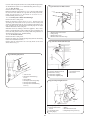
11.7.9. Fit a discharge pipe to the relief valve leading it away
from any electrics or where it might be a hazard. The pipe must
not be less than 15mm in diameter and must run continuously
downward outside the appliance. Refer to Fig 27.
11.7.10. Remove the support brackets and fit the cabinet
bottom panel. Refer to Fig 21.
11.8. Measure and cut the air and flue ducts
11.8.1. Measure the distance from the appliance. Refer to
Fig 29,30.
11.8.2. Add the following distances onto the measurements.
Rear: Air duct length
=
W + 65mm
Flue duct length
=
W + 105mm
Side: Air duct length
=
L + 15mm
Flue duct length
=
L + 142mm
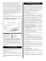
Fig 26-Service Valve Operation
COLD
WATER
INLET
OPEN
CLOSED
CH
FLOW
&
RETURN
OPEN
CLOSED
9
Fig 27-Relief Valve
8
7
1. Flow/Return Manifold
10
2. Discharge Pipe Connection
3. Relief Valve
1
4. Relief Valve Union Connection
5. Bypass Adjuster
6. Drain Point
2
7. Central Heating Flow
8. Central Heating Return
9. Pressure Gauge Capillary
6
5
10. Capillary Clip
4
3
1
Fig 28-Casing Bottom Panel Fixing
2
1. Control Panel Side Support
2. In-line Connector Bracket
3
4
3. Drain Access Opening
4. Bypass Adjuster Access
5. Bottom Panel Fixing Screw (2)
5
6
6. Bottom Panel
15
11.8.3. Mark and cut the air and flue ducts to length. Always
check the dimensions before cutting. Do not cut the drilled or the
expanded ends of the ducts. Make the cuts square and smooth.
11.8.4 Assemble the air and flue ducts and the terminal
assembly as shown in the diagrams. Do not forget to fit the flue
support to an extended duct system. Refer to Fig 31,32.
11.9. Internal fixing of the ducts
11.9.1. Fit the wall sealing collar and fix in place using the clip.
Refer to Fig 33.
11.9.2. Tie a cord around the terminal from inside the flue duct
leaving enough to grip and pull the duct into position.
11.9.3. Push the flue system through the hole in the wall until the
sealing collar has passed through the outside wall.
Note: At this point fit the wall mounting plate/manifold
assembly and the appliance. Refer to Section 11.7.7-10
Fig 32-Flue Terminal and Duct Assembly
10
3
2
4
1
Fig 29-Wall Thickness (Rear Flue) W
1. Flue Duct
2. Air Duct
3. Fixing Screws
4. Flue Terminal
Fig 33-Internal Flue Fixing Assembly
INNER
FACE
OUTER
FACE
W
40
1. Wall Sealing
Gasket
6
2. Flue Terminal
4
1
5
2
3. Flue Duct
4. Air Duct
5. Fixing
Screws
Fig 30-Side Flue Dimension L
6. Flue
Alignment
Ring
CABINET
SIDE
PANEL
Fig 31-Duct Extension Joint
2
3
4
5
{
6
1. Flue Duct
2. Air Duct
3. Fixing Screws
7
4. Flue Duct Support
5. Air Duct Extension
6. Flue Duct Extension
10
11.9.4. Pull the cord to bring the flue sealing collar flush with
outside wall.
11.9.5. Fit and secure the air duct into the clamp as shown in
Fig.34. The air duct fits more easily if it is lubricated with soap
solution. Fully engage the duct into the clamp taking care not to
distort the seal. Tighten the three screws.
11.9.6. Pull the flue duct forward 50mm. Slide the flue clamp
over the fan outlet.
11.9.7. Refit the fan in the appropriate position ensuring that the
flue duct enters the fan outlet by 20mm before tightening the
clamp as shown in Fig 36. Note: Remove the flue hood clamp
wing-nut when a side flue arrangement is used. Replace and
tighten the wing nut after re-fitting the fan.
11.9.8. Re-connect the tubes and electrical connections to the fan
and air flow sensor ensuring that they are correctly positioned
and to the flue sample tube. The RED tube is to the positive
connection. Refer to Fig 22 and 23.
11.9.9. Make good the external brickwork or rendering. Make
good the internal wall as necessary.
11.10. External fixing of the ducts
11.10.1. Prepare the duct assembly as described in Clause 11.8.
11.10.2. From outside ease the assembly through the wall.
11.10.3. Fit and secure the air duct into the clamp as shown in
Fig 35. The air duct fits more easily if it is lubricated with soap
solution. Fully engage the duct into the clamp taking care not to
distort the seal. Tighten the three screws.
11.10.4. Pull the flue duct forward 50mm. Slide the flue clamp
over the fan outlet.
L
1
3
7. Silicone
Sealant
16
1. Auto Air Vent
2. Cap
3. Primary (CH)
Sensor Behind the
Auto Air Vent
4. Flue Hood
5. Flue Hood
Clamp
6. Primary Flow
Manifold
7. Manifold
Fixing
Screw
Fig 35-Auto Air Vent
Fig 34-Air Duct into Clamp
2
1. Boiler Casing
5
1
2. Air Duct
Clamp
Assembly
1
3
2
3. Air Duct
4. Silicone
Rubber Ring
3
5
4
6
4
7
5. Flue Duct
12. Commissioning
11.10.5. Refit the fan in the appropriate position ensuring that
the flue duct enters the fan outlet by 20mm before tightening the
clamp as shown in Fig 36. Note: Remove the flue hood clamp
wing-nut when a side flue arrangement is used. Replace and
tighten the wing nut after re-fitting the fan.
11.10.6. Re-connect the tubes and electrical connections to the
fan and venturi ensuring that they are correctly positioned and
to the flue sample tube. Refer to Fig 22 and 23.
11.10.7. Make good the external brickwork or rendering and the
flue sample tube. The inside edge of the rolled channel on the
terminal assembly will be 10mm from the face of the wall. Make
good the internal wall as necessary.
11.11. Completion of the installation
11.11.1. Remove the automatic air vent cap.
11.11.2. Replace the inner casing cover. Refer to Fig 21.
11.11.3. Check that all the gas and water connections on the
manifold have been tightened.
11.11.4. Fit the facia mounted clock or programmer. Refer to the
instructions sent with the control. Refer to Fig 16.
11.11.5. Remove the facia bottom panel. Connect the mains
supply to the appliance. The lead must be secured with the cable
clamp provided. Check that there is sufficient loose lead to allow
the release of the control box and that the earth lead of the
mains supply is longer than the live and neutral leads. Refer to
Fig 9, 10 and 11.
11.11.6. Test for gas soundness as described in BS6891.
11.11.7. If the appliance is not to be commissioned immediately,
replace the cabinet front and facia bottom panels. Check that the
gas, electricity and water connections are turned off.
Refer to Fig 26.
Benchmark Water Treatment: For optimum performance after
installation, this boiler and its associated central heating
system should be flushed in accordance with the guidelines
given in BS7593:1992 - Treatment of water in domestic hot
water systems. Full instructions are supplied with proprietary
cleansers sold for this purpose. If an inhibitor is to be used
after flushing, it should be used in accordance with the
inhibitor manufacturers instructions.
Suitable flushing agents and inhibitors are available from Betz
Dearborn Tel: 0151 4209563 and Fernox Tel: 01799 550811.
Instructions for use are supplied with these products.
12.1. Domestic hot water circuit: Confirm that the mains water
supply has been flushed out at installation. If not it will be
necessary to disconnect the cold water inlet pipe from the
appliance and thoroughly flush.
12.2. Central heating system: Confirm that the system has been
fully flushed out at installation using a flushing agent. Flush the
system before starting to commission the appliance and, at the
end of the commissioning procedure, add a suitable flushing
agent and drain whilst hot. Immediately refill and re-pressurise.
12.3. Check that the gas service and electricity supply at the
appliance are off.
Check that the mains control knob or programmer is set to off.
Refer to Fig 37.
Check that all the water connections throughout the system are tight.
12.4. Open the central heating system valves on the manifold.
Open all the radiator valves and fill the system. The automatic air
vent will vent the appliance. Remove the inner casing cover to
check that the air vent cap has been removed. Replace the cover
immediately. Vent each radiator in turn to remove air from the
system. Refer to Fig 4, 21, 36.
12.5. Check that the pressure relief valve operates by turning the
knob anti-clockwise until it releases water from the discharge
pipe. Refer to Fig 27.
Fig 36-Flue Duct into Clamp
1
20
2
Fig 37-Facia Panel
3
1
2 3 4 5
6
0
MAX.
MIN.
MAX.
4
10
1. Fan Motor
2. Fan Casing
3. Flue Duct
4. Flue Duct Clamp
9
8
7
1. Mains Supply Light 6. System Pressure
9. CH Temperature
2. CH Demand Light
Gauge
Control Knob and CH
3. Reset Button
7. Programmer/ Clock
On/Off Control
4. DHW Demand Light
Position - (optional) 10. Mains On/Off
5. Burner On Light
8. DHW Temperature
Control Knob
Control Knob
17
12.6. Remove the cap from the front of each pump and turn the
exposed shaft about half a turn using a flat bladed screw driver.
Replace the caps. Refer to Fig 38.
12.7. Set the system pressure by filling the system until a
pressure of 1.5 bar shows on the gauge and check for water
soundness. Release water from the system through the pressure
relief valve until the system design pressure is obtained.
System pressure in bar = Static head + 0.3.
Note 1bar = 10.2 metres of water.
The minimum system pressure should be 1bar.
Set the movable pointer on the gauge to coincide with the
indicating pointer as a permanent record of the set system
pressure.
12.8. The charge pressure of the expansion vessel must not be
less than the static head at the vessel. The initial charge pressure
of the expansion vessel is 0.5 bar (static head of 5 metres). A
schraider type valve is fitted to the vessel for the charge pressure
to be increased if necessary. Refer to Fig 39.
12.9. Refer to BS7074:1, BS5449 and Table 8 for details of the
allowable system capacity.
If the system volume is greater than that which can be
accommodated by the expansion vessel on the appliance then
an extra vessel must be fitted as close to the appliance as
possible in the return pipe.
12.10. Clock/Programmer: The controls fitted to the appliance
should be set at this stage. Detailed instructions are sent with
the control.
12.11. Check that the gas supply is turned off.
12.12. Connect a pressure gauge to the gas valve. Refer to Fig 40.
12.13. Check that the electricity supply is off.
12.14. Set the external controls and the domestic hot water
temperature control knobs on the facia to maximum. The central
heating temperature control must be set at off ( ).
12.15. Turn the gas on at the service cock. Refer to Fig 26.
12.16. Turn on the electricity supply to the appliance. Refer to
Fig 37.
12.17. Open the domestic water inlet valve and fully open a hot
water tap.
12.18. Check Pressure. The boiler should light at minimum
burner pressure of 1.5mbar (G20) or 6.0mbar (G31) and
immediately increase to a maximum of 14.2mbar (G20) or
34.7mbar (G31). The pressures have been set at the factory and
no adjustment of the gas valve should be necessary.
If the maximum pressure is not correct then check that the inlet
pressure to the appliance is 20mbar (G20) or 37mbar (G31). Refer
to Section 9.3.
If the burner does not light then check the overheat thermostat
by pressing the reset button on the facia. Refer to Fig 37. If it still
does not light then turn the hot water tap on and off a few times
to purge the gas line of air. If ignition still does not occur after
several attempts then contact WHS Technical Information
Department, Telephone 0990 266241.
With the boiler alight hot water at a rate of upto 12.6 (±15%)
litres/min will be delivered at full temperature after a short
warm up period.
Slowly close the tap and see the burner pressure drop.
Fully open the tap and the pressure should rise.
Shut the tap and check that the burner goes off, the fan or pump
will continue to run for a short period.
12.19. Set the central heating temperature control to maximum.
12.20. The burner should light at the minimum burner pressure
and remain at this figure for about two minutes and then
increase over a 1 minute period to a pressure equivalent to a
heating load of 25kW. The output will then automatically adjust
to the system load.
Check that all the radiators are heating evenly. Shut down some
of the radiators and see the burner pressure fall and rise again as
they are re-opened.
Fig 38-Pumps
1. Central Heating
Pump
2. Electrical
Connection Cover
Fixing Screw
(not accessable with
the pump in-situ)
3. Expansion Vessel
4. Charging Valve
5. Domestic Hot
Water Pump
6. Pump Cap
7. Impeller
Adjustment
3
4
2
5
7
1
6
Fig 39 Expansion Vessel
4
1
2
3
1. Expansion Vessel
2. Charging Valve
3. Fixing Clip - UP to Release
DOWN to Lock
4. Fixing Screw
Fig 40-Gas Valve
1
9
3
4
5
8
6
2
9
1. Gas Valve
2. Connector
3. Connections
4. Modulator
5. Pressure Adjustment
(shown with cap in place)
18
7
6. Solenoids
7. Inlet Pressure Test Point
8. Burner Pressure Test Point
9. 'O'Rings
Balance the system so that the specified temperature difference
is obtained. Shut the radiators and adjust the bypass until the
same temperature difference is obtained. Refer to Fig 41.
Set the room thermostat to minimum and check that the burner
goes out and comes back on after a period of about three
minutes after the room thermostat is reset to maximum. Switch
the burner off by setting the CH temperature control knob to off.
12.21. Turn off the electricity to the appliance. Drain the heating
system as described in Section 15.3.1. Refill and re-pressurise as
described in Section 12.4-8 adding a suitable proprietary
inhibitor if necessary. Further information is available from WHS
Technical Information Department, Telephone 0990 266241.
12.22. Completion of Commissioning: Disconnect the pressure
gauge and tighten the test point screw. Restart the appliance and
check for gas soundness around the test point screw.
Refer to Fig 40.
12.23. Refit the cabinet front panel.
12.24. If the appliance is to be passed over to the user
immediately then set the controls to the users requirements.
Refer to Section 13.
14. Inspection and Servicing
14.1 SERVICING
To ensure continued efficient operation of the appliance it must
be checked and serviced as necessary at regular intervals. The
frequency of servicing will depend upon the particular
installation conditions and usage, but once per year should
generally be adequate. The extent of the service required by the
appliance is determined by the operating condition of the
appliance when tested by fully qualified engineers.
Any service work must be carried out by competent engineers
such as British Gas or Corgi registered personnel.
14.2. Inspection
14.2.1 Check that the flue terminal and the terminal guard, if
fitted, are clear and undamaged.
14.2.2 If the appliance is in a compartment or cupboard, check
that the service space around the appliance is clear. Refer to Fig 3.
14.2.3 Check all the joints and connections in the system and remake any that show signs of leakage. Refill and re-pressurise as
described in Section 12.4-8 - Commissioning.
14.2.4 Operate the appliance and take note of any irregularities.
Refer to Section 18, Fault Finding for rectification procedures.
Check the combustion performance. Remove the screw at the
sample point, on top of the appliance. Connect the sampling
meter. Refer to Fig 17. With the appliance at maximum rate and
stable in the DHW mode expect readings of 4.5 - 6.5 % CO2 and
0.0025-0.009% CO. Refit and tighten the screw after the test.
These figures cover all the flue lengths.
14.2.5 Disconnect the electrical supply at the mains and turn
off the gas supply at the gas service cock on the appliance
before starting any service procedures.
14.2.6 Always test for gas soundness after the service has been completed.
14.3 Component Access
14.3.1 To service the appliance it may be necessary to remove
some or all of the following parts to gain access to components
which may need to be checked or replaced.
14.3.1.1 Cabinet front panel. Lift and pull away.
14.3.1.2 Facia/Control box. Unscrew the two screws and lower.
Refer to Fig 21.
14.3.1.3 Inner casing cover. Unscrew the four screws and
remove. Refer to Fig 21.
14.3.1.4 Combustion chamber cover. Unscrew the four screws,
slacken the flue hood J-bolts and remove. Refer to Fig 42.
14.3.1.5 Fan. Carefully pull off the electrical connections, pull off
the tubes from the air flow sensor and flue sample tube, unscrew
the assembly fixing screw. Unscrew the flue duct clamp to
release the flue duct and slide the fan assembly out. Refer to Fig
22, 23 and 34.
14.3.1.6 Flue hood. Remove the fan. Unscrew the two J-bolts and
remove. Refer to Fig 42.
14.3.1.7 Burner blade assembly. Remove the spark and sensing
electrodes and the support brackets. Refer to Section 15.4.2/3.
Unscrew the blade assembly fixing screws and loosen the two
locating screws. Lift the blade assembly from the appliance.
Refer to Fig 43, 44, 45.
14.3.1.8 Cabinet bottom panel. Unscrew the two screws and
remove. Refer to Fig 28.
14.4 Component Cleaning
Only use a non-metallic brush to clean components.
14.4.1 Clean the fan, taking care not to block the air flow detector.
14.4.2 Clean the burner blade assembly to ensure that all the
ports are clear.
14.4.3 Clean the electrodes. Replace if there is any deterioration
of an electrode.
14.4.4 Clean the burner manifold. Inspect the burner manifold and
remove any deposits. Do not use any metal probes to clean the injectors.
Fig 41-Bypass Adjuster and Drain Point
9
10
7
8
5
6
Pipework Connections
1. Relief Valve Discharge
2. Central Heating Return
3. Central Heating Flow
4. Cold Water inlet
5. Domestic Hot Water Flow
4
3
2
1
6. Gas Inlet
7. Bypass Adjuster
8. Drain Point
9. Facia Panel
10. Bottom Panel
12.25. If the appliance is to be left inoperative in frosty
conditions then check that the programmer, if fitted, is set to Off.
The appliance will operate under the control of the integral frost
protection facility. Do not switch the electricity supply off.
12.26. If there is any possibility of the appliance and the system
being left totally unused in freezing conditions then switch off
the gas and electricity and drain the appliance and the system.
Refer to Fig 41.
13. User Information
13.1 Tell the user how to operate the appliance and
hand over the Users Instructions leaflet.
13.2 Tell the user what to do if the heating system is not to be
used in frosty weather.
13.3 Tell the user the sealed system set pressure.
13.4 Tell the user of the importance of regular servicing.
Worcester Heat Systems Ltd. offer a comprehensive maintenance
contract.
13.5 Set the system controls to the user’s requirements.
13.6 Complete and hand over to the user the Benchmark
Log-Book.
19
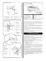
Fig 42-Flue Hood Fixing
Fig 45-Burner Assembly
1
2
2
1
3
4
3
8
6
4
1. Clamp Location
2. Flue Hood Clamp
7
1. Burner Blade Assembly
Fixing Screw (2)
2. Burner Blade Assembly
3. Burner Location Slot
4. Burner Manifold With
Injectors
3. Flue Hood
4. J-Bolt and Wing Nut
5
5. Manifold Support Bracket
6. Burner Blade Locating
Screw
7. Manifold Fixing Screw
8. O-Ring
Fig 43-Spark Electrode
1
2
14.4.5 Clean the primary heat exchanger. Cover the burner
manifold. Remove any deposits from the heat exchanger gaining
access from the top and bottom. Carefully straighten any
distorted fins on the heat exchanger.
14.4.6 Check the combustion chamber insulation. Replace the
insulation if there is any damage or deterioration. Refer to
Section 15.4.4.
14.4.7 Clean the controls in-situ using a non-metallic brush.
14.4.8 Carefully refit any components removed in the reverse
order. Check that all screws are tight and the connections
properly remade.
14.4.9 Recommission the appliance, as necessary, for correct
operation to the users requirements.
1. Spark
Electrode
Assembly
3
5
2. Burner Blade
Assembly
3. Fixing Screws
(2)
4. Burner Support
Bracket
4
5. Electrode Lead
Connection
(Push on)
15. Replacement of Parts
15.1 Important: Turn off the gas and electricity supplies
before replacing any components.
After the replacement of any components always check for gas
soundness where relevant and carry-out functional checks as
described in Section 12 - Commissioning.
Any O-ring or gasket that appears damaged must be replaced.
Complete gasket and O-ring packs are available for the gas and
water connections on the appliance.
15.2. Component Access:
Refer to Section 14.3.1.1-4 for access to components.
15.3 Draining the Appliance
15.3.1 Primary System : Turn off the heating flow and return
valves at the appliance. Refer to Fig 26. Fit a tube to the drain
connection and open about one turn by turning anti-clockwise.
Close the drain tap when the water flow from the appliance has
stopped. Refer to Fig 41.
15.3.2 DHW Circuit : Turn off the mains cold water supply at the
appliance. Refer to Fig 26. Open a hot tap below the level of the
appliance to drain the domestic water circuit in the appliance.
15.3.3. Important: A small quantity of water will remain in
some components even after the appliance has been drained.
Cover any electrical components when removing these items.
15.4 Component Replacement:
Refer to Fig 17 for an indication of the location of the various
components.
Gap
Dimension
5mm ±1
Fig 44-Flame Sense Electrode
4
1. Flame Sense
Electrode
2. Electrode
Mounting and
Burner Support
Bracket
1
3. Fixing Screws (2)
4. Burner Blade
Assembly
2
3
20
Replace any components removed from the appliance in the
reverse order using new gaskets/O-rings/sealant where
necessary. Always check that any electrical connections are
correctly made and that all screws are tight.
Remove casing and cover panels and lower the facia, as
necessary, to gain access to the controls. Refer to Clause
14.3.1.1-7.
15.4.1. Gas valve
Disconnect or unplug the electrical connections at the valve.
Remove the bottom panel. Unscrew the four flange screws at the
top and the union connection at the bottom manifold and
remove the assembly. Use the new O-rings provided when fitting
the new valve. Refer to Fig 40.
Set the gas valve:
1. Connect a pressure gauge to the burner pressure test point on
the gas valve. Refer to Fig. 40.
2. Switch on the gas and electrical supplies. Check for gas
tightness at the gas valve inlet.
3. Carefully pull off a connection from the Modureg adjuster on
the gas valve. Fully open a hot water tap. The burner will light
and operate at the minimum pressure.
4. Remove the cap from the Modulator.
5. Adjust the Modulator with a 3mm hexagonal key to give the
minimum pressure appropriate to the gas, clockwise to increase,
and counter-clockwise to decrease the pressure. 1.5 mbar for
natural gas (G20) or 6 mbar for propane (G31). Refer to Fig. 46.
15.4.2. Spark Electrode
Remove the inner casing cover.
Carefully pull off the leads at the electrode assembly. Unscrew
the two screws and remove the spark electrode assembly from
the burner. Refer to Fig 43.
15.4.3. Flame Sensing Electrode
Remove the inner casing cover.
Separate the electrode lead in-line connector. Release the locknut
on the support bracket and remove the sensing electrode from
the burner. Refer to Fig 44.
15.4.4. Burner and Manifold
Remove the electrodes.
Remove the burner support brackets.
Remove the combustion chamber cover. Unscrew the two blade
assembly fixing screws and loosen the two locating screws. Lift
the blade assembly from the manifold. Remove the two
extended screws and lift out the manifold assembly. Do not omit
the O-ring when fitting the new burner. Refer to Fig 45.
15.4.5. Combustion Chamber Insulation
Remove the combustion chamber cover.
Slide out the side insulation pads and then lift out the rear pad.
Fit new insulation pads in the reverse order. Remove and replace
the pad from the combustion chamber front cover. Refer to
Fig 47. To avoid the risk of fine particles dampen the pads before removal.
15.4 6. Pressure Gauge
Drain the primary system. Refer to 15.3.1. Lower the facia and
unclip the gauge. Pull out the clip from the manifold and remove
the capillary. Refill and pressurise as described in Section 12.4-8 Commissioning. Refer to Fig 27 and 48.
15.4.7. Relief valve
Drain the primary system. Refer to 15.3.1. Lower the facia.
Disconnect the relief valve drain pipe. Undo the union
connection and remove the relief valve. Refill and pressurise as
described in Section 11 - Commissioning. Refer to Fig 27.
Fig 46-Burner Pressure Adjuster (Modulator)
1
2
3
Fig 47-Combustion Chamber Insulation
7
4
1
6
2
5
1. Modulator
2. Connections
3. Min/Max Pressure Adjuster
4. 2mm Hexagonal Key
(Maximum Pressure
Adjustment)
5. 3mm Hexagonal Key
(Minimum Pressure
Adjustment)
6. Modulator Cap
7. Burner Pressure Test Point
3
4
3
1. Flue Hood Clamp Location Slots
2. Combustion Chamber Casing
6. Switch the appliance off. Refit the electrical connector to the
Modulator. With the hot water tap fully open, turn on the
appliance. The burner will light at the minimum pressure, and
then quickly increase to the maximum pressure. Adjust the
Modulator with a 2mm hexagon key to give the maximum
pressure appropriate to the gas, clockwise to increase and
counter-clockwise to decrease the pressure. 14.2 mbar for
natrural gas (G30) or 34.7 mbar for propane (G31).
NOTE: if there is any difficulty in achieving these pressures then
check the inlet pressure at the gas valve. Refer to Section 9.3.
7. Turn off the hot water tap.
8. Replace the Modulator cap.
9. Run the appliance in each mode to check the setting
pressures. Central heating, 8.3mbar for natural gas (G20) or
19.2mbar for propane (G31). Refer to Section 15.4.11 if
necessary, to set the central heating pressure.
10. Switch off the appliance and disconnect the pressure gauge.
11. Relight the appliance and check for gas soundness.
3. Side Insulation Pads
4. Rear Insulation Pad
15.4.8. Flow Regulator
Drain the hot water circuit. Refer to 15.3.2. Lower the facia.
Remove the bottom panel.
Slacken the inlet water pipe at the manifold. Disconnect and
remove the flow switch. The flow regulator and its associated
plastic retaining collar are located in the outlet of the flow switch
body. Note the orientation of the regulator inside the flow switch
body, remove the regulator and collar. Ensure the new regulator
is correctly aligned and then insert the plastic collar. Ensure the
flow switch is refitted with the arrow pointing upwards.
Refer to Fig. 49.
21
15.4.9. Inlet Water Filter
Drain the hot water circuit. Refer to 15.3.2. Remove the bottom
panel. Lower the facia.
Disconnect the inlet water pipe at the manifold and the flow
switch. Remove the filter. Ensure that the new filter is correctly
aligned. Refer to Fig 49.
15.4.10. Flow Switch
Drain the hot water circuit. Refer to 15.3.2.
Lower the facia.
Unscrew and remove the flow switch. Ensure that the new
switch is correctly aligned with the arrow pointing upwards..
Refer to Fig 49.
15.4.11. Control Board
Remove the bottom cover from the facia by releasing the three
screws. Unplug or disconnect all the connections at the board.
Refer to Fig 9,10 and 11.
Unscrew and lower the facia. Refer to Fig 21.
Fig 49-Domestic Hot Water Control Assembly
7
6
4
9
5
Fig 48-Pressure Gauge Fixing
2
3
3
1
4
4
1
8
2
1. Pressure Gauge
2. Pressure Gauge Fixing Clip
3. Pressure Gauge Capillary
1. Domestic Hot Water
Expansion Vessel
Connection (optional)
2. Inlet Union Connecton
3. Flow switch body
4. Sealing Washer (2)
5. Flow Regulator
4. Facia
Unclip and remove the splash guard. Unscrew the four screws
and remove the control board assembly. Remove the control
board from the mounting plate by releasing the four clip fixings.
Pull off the transformer and fit it to the new control board
ensuring that it is properly aligned. Ensure that all connections
are correctly made when re-assembling the control board.
Refer to Fig 51 and 52.
Set the CH pressure:
1. Check the operation of the appliance to determine the
minimum and maximum set burner pressures.
2. Reset, if necesssary. Refer to Section 15.4.1.
3. Operate the appliance in the central heating mode with the
control at maximum.
4. Turn the CH gas pressure adjuster fully clockwise, wait until
the burner pressure has stopped increasing and then slowly turn
the CH gas pressure adjuster anti-clockwise until the burner
pressure is 8.3mbar for natural gas (G20) or 19.0mbar for
propane (G31). Refer to Fig 51.
5. After completing the adjustments, check the pressure settings
in both modes of operation and re-adjust as necessary.
6. Hexagonal Fixing Screw
7. Domestic Hot Water
Heat Exchanger
Connection with
O-Ring
8. Inlet Water Filter
9. Backing Collar
15.4.12. Transformer
Follow the instructions given in Section 15.4.11 to remove the
transformer.
15. 4 .13. Pump Control Board
Remove the bottom cover from the facia. Refer to Fig 11. Unplug
and remove the pump control board. Refer to Fig 53.
15.4.14. Programmer
Remove the programmer assembly from the facia by carefully
pulling it from the facia to free the clips. Unplug the connection
at the control board. Comprehensive setting instructions are sent
with the new programmer. Refer to Fig 16.
15.4.15. Fan
Remove the inner casing cover.
Refer to 14.3.1.1-5. Ensure that all the connections are correctly
made to the new fan. Refer to Fig 22 and 23.
15.4.16. Air Flow Detector
Remove the inner casing cover.
Refer to 14.4.1-5 to remove the fan assembly. Unscrew and
remove the detector. Check that the tubes are correctly fitted.
Refer to Fig 22 and 23.
22
15.4.17. CH Sensor
Remove the inner casing cover.
Carefully pull off the connections and release the clip to remove
the sensor. Apply heat transfer paste to the face of the new
sensor. Refer to Fig 55. Note: If a left-hand flue is fitted then it is
easier to remove the sensor and clip before pulling off the
connections
15.4.18. DHW Sensor
Lower the facia.
Carefully pull off the connections and unscrew the clip to remove
the sensor. Apply heat transfer paste to the face of the new
sensor. Refer to Fig 56.
15.4.19. Boiler Overheat Thermostat
Remove the inner casing cover.
Carefully pull off the connections. Unscrew the thermostat
locknut. Remove the split pin and pull out the phial from the
heat exchanger pocket. Apply heat transfer paste to the phial.
Refer to Fig 57.
15.4.20. CH and DHW Pumps
Lower the facia.
Drain the primary system. Refer to 15.3.1. Pull out the pump
fixing clips and withdraw the pump. Improved access can be
achieved by removing the expansion vessel. Refer to Section
15.4.21. Disconnect the leads at the appropriate pump head.
Refer to Fig 17. Note: There will be a small amount of water still
in the pump body. Refer to Fig 58.
The pump head is a Grundfos 15/60 and may be replaced
leaving the body in place if necessary. Take care not to mark the
mating surfaces if this done. Set to maximum. Refill and
pressurise as described in Section 12.4-8 - Commissioning.
15.4.21. Expansion Vessel
Lower the facia.
Drain the primary system. Refer to 15.3.1. Unscrew the fixing
screw. Release the vessel connection to the system by pushing
the clip upwards and remove the vessel. Note: There will be a
small amount of water in the vessel. Refill and pressurise as
described in Section 12.4-8 - Commissioning. Refer to Fig 54.
15.4.22. DHW Heat Exchanger
Lower the facia.
Drain the primary system and the DHW circuit. Refer to 15.3.1
and 15.3.2.
Carefully unscrew and remove the pipe connections to the heat
exchanger. Release the clips and remove the heat exchanger.
Note: There will be a small amount of water still in the heat
exchanger. Do not strain the pipes when re-connecting them to
the heat exchanger.
Fig 52-Control Panel Fixing
1
2
3
1. Fixing Clips (4)
2. Control Board
3. Mounting Plate
Fig 53-Pump Control Board
1
2
6
7
5
1. Pump Control Board
2. X1 Connection
3. Control Panel Pivot Point
4. X3 Connection
3
4
5. X2 Connection
6. Fixing Clip (1)
7. Cable Clamp
Fig 51-Control Board Mounting Plate Fixing
1
2
Fig 54 Expansion Vessel
4
3
1
6
7
2
5
4
3
1. Fixing Screws (4)
7. Central Heating Mode
2. Mounting Plate
Gas Pressure Adjuster
3. Control Panel Pivot Point
4. Facia
5. Pressure Gauge
6. Transformer
Note: Splash guard not shown.
1. Expansion Vessel
2. Charging Valve
23
3. Fixing Clip - UP to Release
DOWN to Lock
4. Fixing Screw
Use new seals and gaskets where necessary. Refill and pressurise
as described in Section 12.4-8 - Commissioning. Refer to Fig 59.
15.4.23. Auto Air Vent
Remove the inner casing cover.
Drain the primary system. Refer to 15.3.1. Unscrew and remove
the auto air vent. Remove the cap from the newly fitted vent.
Refill and pressurise as described in Section 12.4-8 Commissioning. Refer to Fig 35.
15.4.24. Primary Gas to Water Heat Exchanger
Remove the inner casing cover.
Drain the primary system. Refer to 15.3.1. Remove the fan
assembly, flue hood, CH sensor (at the left hand side) and
overheat thermostat from the heat exchanger. Disconnect the
heat exchanger at the back panel by releasing clips at the right
and left hand sides. Refer to Fig 60.
Withdraw the heat exchanger from the appliance. Note: There
will be a small amount of water still in the heat exchanger. Use
new seals and gaskets where necessary. Refill and pressurise as
described in Section 12.4-8 - Commissioning.
15.4.25. Air Pressure Switch
Remove the inner casing cover.
Remove the switch by carefully prising away from the mounting
tabs of the 'horseshoe' bracket.
Ensure that the connections are correctly made to the new
switch. Refer to Fig. 61.
Fig 56-Domestic Hot Water Sensor
2
4
1
3
1. Domestic Hot Water Sensor
2. Fixing Clamp
3. Clamp Fixing Screw
4. Domestic Hot Water Flow Pipe
Fig 57-Boiler Overheat Thermostat
1
2
3
4
8
Fig 55-Primary (CH) Sensor
1
5
6
2
3
7
4
1. Lock Nut
2. Overheat Thermostat Head
3. Boiler Inner casing
4. Thermostat Capillary
5. Thermostat Capillary Clip
5
6
1. Auto Air Vent
2. Primary (Central Heating)
Sensor
3. Fixing Clamp
4. Primary Heat Exchanger Clip
5. Primary Flow Manifold
6. Primary Flow Manifold Fixing
Screw (1)
6. Thermostat Phial
7. Thermostat Pocket
8. Flue Hood
Fig 58-Pump Fixing-Rear View
2
4
5
3
7
6
7
1
8
1. Pump Body
2. Electric Connections
Covers
3. Non-Return Valve
4. Fixing Clip (2)
24
5. Non-Return Valve Test Button
6. O-Ring
7. Back Panel Connectors
8. Pump Body Fixing Screws (3)
Fig 59-Domestic Hot Water Heat Exchanger
Fig 60-Primary Heat Exchanger Fixing
1
1
2
1. Fixing Clip (2)
2. Domestic Hot
Water Heat
Exchanger
2
3
5
3. Cold Water Inlet
6
5
4. O-Ring
4
5. Domestic Hot
Water Flow
4
1. Fixing Clip (2)
2. Clip Locating Channel
3. Primary Heat Exchanger
4. Clip Locating Groove
3
Fig 61-Air Flow Switch
5
5
1. Air Pressure Switch
2. Electrical Connection
3. Electrical Connection
4. Air Flow Sensing Tube Connections
REAR
FRONT
5. O-Ring
6. Appliance Back Panel
1
+ Positive
Negative
2
3
5. Plastic 'horseshoe' mounting bracket
5
4
25
16. Short Parts List
GC
Key
No. Number
Description
Manufacturer
Qty
WHS
Number
1
1
2
3
4
4
5
6
7
8
9
E02-827
E02-828
E02-825
E02-892
E02-889
E02-891
E02-838
299-506
397-677
395-767
E02-823
Gas Valve - NG
Gas Valve - LPG
Ignition Electrode
Flame Sense Electrode
Burner E19 - NG
Burner E19 - LPG
Insulation Pack
Pressure Gauge 4 Bar Dark Grey
Pressure Relief Valve
Flow Regulator 12 Litres Red
Flow Switch
Dungs
Dungs
Buccleugh
Vernitron
Furigas
Furigas
Worcester
Cewal
Caleffi
Worcester
Altecnic-MG
1
1
1
1
1
1
1
1
1
1
1
8 716 101 971 0
8 716 101 972 0
8 716 142 127 0
8 716 121 207 0
8 716 142 642 0
8 716 142 643 0
8 716 192 224 0
8 716 142 300 0
8 716 142 416 0
8 716 141 061 0
8 716 101 973 0
11
12
13
14
15
16
17
18
19
20
21
22
23
24
25
26
27
28
29
30
31
E02-830
299-516
E02-831
E02-829
299-363
E02-835
E02-835
E02-834
E02-880
E02-881
229-029
299-321
E00-717
371-528
E02-833
E02-836
E02-837
299-357
324-822
E02-832
E02-826
Control Board
Transformer
Pump Control Board
Fan Assembly
Air Flow Detector
CH Sensor
DHW Sensor
Over Heat Thermostat
CH Pump
DHW Pump
Expansion Vessel
Heat Exchanger DHW
Auto Air Vent
Heat Exchanger Primary
Air Pressure Switch
Gasket/O'ring Pack - Water
Gasket/O'ring Pack - Gas
Fuse Pack
Inlet Water Filter
Main Harness
Spark Electrode Lead
Heatronic
ERA
Pactrol
SEL
Worcester
Shibura
Shibura
Ranco
Grundfos
Grundfos
Zilmet
Dong IL
Intermes
Giannoni
Huba
Worcester
Worcester
Worcester
Worcester
Worcester
Worcester
1
1
1
1
1
1
1
1
1
1
1
1
1
1
1
1
8 748 300 297 0
8 747 201 248 0
8 716 146 302 0
8 716 121 063 0
8 716 144 000 0
8 716 142 376 0
8 716 142 376 0
8 716 142 372 0
8 716 143 109 0
8 716 143 111 0
8 716 142 506 0
8 716 101 976 0
8 716 140 500 0
8 716 142 804 0
8 716 156 744 0
8 716 192 225 0
1
1
1
1
1
8 716 192 226 0
8 716 192 206 0
8 716 148 401 0
8 716 121 014 0
8 716 121 196 0
22
4
3
2
9
21
31
19
24
20
12
1
14
13
11
15
30
7
6
25
16
17
18
23
29
8
26
26
28
5
27
17. Operational Flow Diagrams
CENTRAL HEATING FUNCTION
MAIN SWITCH
ON
CENTRAL
HEATING
DEMAND
CH light On.
Pump On.
Fan high
2 second then
Low Speed.
Ignition
Sequence.
Burner Light
on
Three minute
wait
Green Light
On
Two minute
minimum
burner
pressure then
ramp up
pressure over
next one
minute
Room
thermostat
and/or mains
programmer
(or link) On
AND
AND
Electronic
facia
programmer
(if fitted) On
AND
ST13 link In
AND
CH control
knob On
Modulate gas
to maintain
flow
temperature
set by control
knob
DEMAND
END
Pump
continue four
minutes.
Fan continue
fifteen
seconds
Over temperature shutdown if flow
temperature
5°C above set
value
Gas valve Off.
(CH light still
on. Pump still
On)
DOMESTIC HOT WATER FUNCTION
MAIN SWITCH
ON
DOMESTIC
HOT WATER
DEMAND
(Priority over
CH demand)
HW light On.
Pump On.
Fan high
2 Seconds
then Low
Speed.
Ignition
Sequence.
Burner on
Ten second
wait
Flow switch
On
(Tap open)
Green Light
On
Fan continue
fifteen
seconds
Four second
ramp to max.
gas pressure
Fan Speed
Change at
Approx mid
pressure
Modulate gas
to maintain
delivered
water
temperature
at value set by
control knob
Gas valve Off.
(HW light still
on. Pump still
On)
Over
temperature
shut-down if
water
temperature
8°C above set
value
Burner shutdown if
primary
temperature
85°C
(until 74°C)
27
DEMAND
END
Possible
overrun
condition
within next
four minutes
(See next
section)
OVERRUN FUNCTION
Within four
minutes of last
hot water
demand
AND
primary
temperature
above 80°C
If heat
demand has
occured in last
30 minutes
Run pump
until primary
drops to
80°C
If heat
demand has
NOT
occured in last
30 minutes
Run pump
until primary
drops to
80°C
If primary
temperature
still increases
above 90° C
Run pump for
2 seconds
AUTOFROSTSTAT
FUNCTION
AUTOFROSTAT FUNCTION
No demand
and primary
temperature
below 8°C
Internal
“Autofrostat”
demand
Wait in normal
off state for
30 minutes
Run pump for
four minutes
Monitor
central
heating
sensor
Below
5°C
5°C
to
9°C
Above
9°C
Commence normal
central heating mode
until temperature
reaches 30°C
28
Return to
normal off
state
The electronic control system for this appliance uses the four
lights on the facia. These show the normal operating status and,
by flashing, help to provide a fault diagnostic system. With
individual or groups of lights being permanently off, on or
flashing, every normal fault can be identified.
18. Fault Finding
Note: This information is for guidance only. Worcester Heat
Systems cannot be held responsible for costs incurred by persons not deemed to be competent.
Preliminary Checks.
Electrical system checks are the first actions to be
carried-out during a fault finding procedure. On
completion of the Service or a fault finding task which has
necessitated the breaking and remaking of electrical
connections, check (a) Earth Continuity, (b) Short Circuit, (c)
Polarity, (d) Resistance to Earth.
INDICATOR
CH Light Flashes
Slow
CH & DHW Lights Flash
Slow
CH Light Flashes
Fast
DHW Light Flashes
Fast
RESULT
Slow Flash - One per second
Can be cleared by pressing the facia reset button for at least one
second.
Fast Flash - Five per second
Can be cleared by removing the fault and/or switching the
mains off and on.
CAUSE
Burner Lock - Out.
Primary Overheat.
Sensor Fault.
Air Pressure Fault or
Blocked Flue or
Water Pressure Fault
ACTION
Flame Detect Fault.
Internal TestFault.
Overheat Thermostat Operated in
Demand status.
Primary (CH) or DHW Sensor Open
or Short Circuit.
Internal Reference Voltage Error.
APS Permanently Closed.
APS Does not Close.
APS Open While Burner is On.
Press Facia Reset Button For 1 Second.
As Above.
Switch Mains Supply Off /On
or Rectify Fault.
Switch Mains Supply Off/On
or Recify Fault.
Fault Finding Chart
Select the appropriate indicator light situation. Refer to the appropriate section of the chart. This system assumes that the appliance has
been operating correctly upto the point of failure.
LIGHT SITUATION DURING FAULT
FAIL POINT A
No lights at all
FAIL POINT C
No green light
(Red lights work)
No red lights
(Green light working)
FAIL POINT D
No light
(Other lights work)
FAIL POINT F
Light on constant
(CH knob in OFF
position)
FAIL POINT G
FAIL POINT B
No light
(Other lights work)
FAIL POINT E
2 lights flashing slowly
FAIL POINT H
Flashing slow
FAIL POINT I
Flashing fast
POWER ON
(Green)
CH DEMAND
(Red)
FAIL POINT J
Flashing fast
HW DEMAND
(Red)
Other faults not covered by above
29 not covered by above
Other faults
BURNER ON
(Red)
FAIL POINT K
FAIL POINT K
Is the facia on/off
switch turned on?
`(Clockwise)
No
Turn switch on.
FAIL POINT A
Yes
Is there a 230V AC live
supply across
Terminal ST12 pins L
and N
No
Check electrical
supply to boiler.
Yes
Has fuse F1 blown?
No
Replace control board
(Section 15.4.11)
Yes
Replace fuse and investigate cause. Suggestions: Cable
damage, connections to (or faults within) pump, fan,
external 230V controls, transformer or board.
No
Yes
This could be caused
by the board or
internal
wiring/components
Remove control board from facia
(See Section 15.4.12) and separate transformer from board.
Measure resistance across the
two pairs of adjacent pins on the
transformer. Is any pair above
100 ohms?
No
Replace
control
board
(Section
15.4.11).
FAIL POINT C
FAIL POINT B
Has fuse F2 blown?
Yes
Replace transformer.
With CH control knob
fully clockwise, does
the boiler ignite and
appear to run
normally in central
heating mode?
Yes
FAIL POINT D
Red diode is
damaged. Replace
control board.
(Section 15.4.11)
No
Is there 230V AC
across terminal ST8
pins LR and N?
No
There is no heat
demand. Check room
thermostat or mains
programmer (or link).
Yes
Is there a link at
terminal ST13 pins 1
and 2?
No
Insert or tighten link
Yes
Is there an electronic
programmer at
position ST5 at righthand end of board?
No
Yes
Remove programmer
connector from board
edge. Does CH lamp
now light?
No
Yes
Correctly set or
replace electronic
programmer.
30
Replace control board.
(Section 15.4.11).
Green diode is damaged.
Replace control board.
(Section 15.4.11)
No
Yes
Remove multiway
connector from board
position ST16. With
tap still open is there
continuity across
contacts 19 and 20
(2 pink wires)?
No
Separate the 2 way in-line
connector to flowswitch
(fitted to boiler side
panel). With tap still open,
is there continuity across
the two terminals still
fixed to side panel? Take
care not to damage
terminals
Replace
Flow Switch
No
Yes
Yes
Red diode is
damaged. Replace
control board.
(Section 15.4.11)
Is the boiler fully
water pressurised and
is all air vented?
Replace control board.
(Section 15.4.11).
No
Repair or replace
wiring/harness
Is the boiler in a very
cold environment (less
than 5°C)?
FAIL POINT F
FAIL POINT E
With a hot water tap
fully open, does the
boiler ignite and
appear to run
normally in hot water
mode?
Rectify fault.
No
Replace control board
(Section 15.4.11 )
Note: A wet board
could cause this fault
Yes
Boiler is running in
“Autofrost stat” mode.
See Section 17.
Yes
Create a central
heating demand. Does
the CH pump run?
No
Yes
Remove pump
connector ST15 from
control board and
retsart boiler in CH
mode. Is there mains
230V pump output
from board
No
Replace control board
(Section15.4.11 )
Yes
FAIL POINT G “Primary Overheat”
Replace CH pump
(Section 15.4.20)
or replace cable
Create a DHW
demand. Does the
DHW pump run?
No
Yes
Is there mains 230V
across pins 1 & 2 of
terminal X3 of pump
relay PCB?
No
Yes
No
Yes
Separate 6 way in-line
connector and check
continuity across
terminals of orange
wires (which run to
back of boiler). TAKE
CARE NOT TO
DAMAGE TERMINAL.
Is there continuity?
Is there 22-26V dc
across pins 1 & 2 of
terminal X1 of pump
relay PCB?
Yes
Replace pump relay
PCB (Section15.4.13 )
No
Yes
Repair or replace main
harness
Remove inner casing
cover and inspect the
primary sensor (left of
heaty exchanger). Is it
correctly fixed to
pipe?
No
No
Check connections
and wiring back to
connector ST23 on
main board
Yes
Replace DHW pump
(Section 15.4.20 )
or replace cable
Remove multiway
connector from board
position ST16. Is there
continuity across
contacts 5 & 6 (two
orange wires)?
Is there mains 230V
across pins 1 & 2 of
terminal X2 of pump
relay PCB?
Re -fix sensor to pipe
Yes
Replace control board
(Section15.4.11 )
31
Repair or replace
thermostat or orange
wires to thermostat
No
Replace control board.
(Section15.4.11 )
Is the gas supply
connected and at the
correct pressure?
No
Rectify gas supply
problem.
Yes
Remove front panel.
Reset and restart the
boiler. Can a flame be
seen through the spy
glass?
No
Remove inner cover.
Reset and restart the
boiler. Does a spark
occur across the
electrodes?
No
Are the electrodes and
gap and connections
in good order?
No
Repair or replace
electrodes
(Section 15.4.2/3)
or HT leads
Yes
Replace control board.
(Section 15.4.11).
Yes
Remove the 5 way
connector from the
gas valve and
measure the DC
voltage across the
violet and grey wires
and then brown and
yellow wires during
the spark period. Is
there 20-30V DC in
both cases?
FAIL POINT H “Burner Lockout”
Yes
No
Yes
Yes
Replace gas valve.
(Section 15.4.1 ).
Turn off boiler. Remove
inner cover and
combustion chamber
cover. Is the sense
electrode and lead in
good condition and is
gap correct.
No
Replace control board.
(Section 15.4.11 ).
Repair or replace flame
sensor
(Section 15.4.3)
or wiring.
Yes
Remove multiway
connector from board
position ST16.
Is there continuity
from contact 11 (white
wire) to flame sensor?
No
Yes
Does the flashing fault
signal occur at the
start of a demand?
No
Remove multiway
connector from
control board position
ST16. Is there
continuity of violet
and brown wires
between connectors
Flashing occurs at end
of demand. Replace
gas valve.
(Section 15.4.1).
Yes
Replace control board (Section 15.4.12).
Note: It is not possible to reliably Check
the cross-light performance of the burner.
In the unlikely event of such a fault,
investigate flue problems or replace
burner or injector. (Section 15.4.4).
32
No
Repair or replace
harness.
Is the multiway
connector at board
position ST16 pushed
fully home on to the
board?
No
Push fully home.
FAIL POINT I “Sensor Fault”
Yes
Remove multiway
connector from board
position ST16. Test
resistance across
contacts 17 and 18
(yellow & either black
wires). Is it between 1
kohm and 30 kohm?
No
Yes
Replace control board
(Section 15.4.11).
No
Separate 6 way in-line
connector and check
continuity of red wires
to determine a harness
fault. Repair or replace
wiring
No
Repair or replace
harness or main
connector or in-line
connector.
Yes
Check or replace
DHW sensor.
(Section 15.4.18).
Yes
Test resistance across
contacts 12 & 13
(red wires).
Is it between 1 kohm
and 30 kohm?
Is there continuity
from contacts 17 and
18 to DHW sensor?
No
Is there continuity
from contacts 12 and
13 to CH sensor?
Yes
Check or replace
CH sensor.
(Section 15.4.17).
33
Does this fault only
occur in CH or DHW
mode?
Yes
No
Remove fan connector
from board position
ST1 and restart boiler
in the fault mode.
After 5 seconds is
there mains 230V
from the left (N) track
at ST1 and right (L)
track if DHW mode?
Centre (L) track if CH
mode?
No
Replace control board.
(Section 15.4.11).
Yes
FAIL POINT J “Air or Water Pressure Fault”
Repair or replace fan
(Section 15.4.15) or
cable.
Does the fan run at
all before the fault
occurs?
No
Turn off boiler. Remove
multiway connector
from board position
ST16. Is there
continuity across the
green wires?
No
No
Check black wires and
in-line connector.
No
Replace control board
(Section 15.4.11)
Yes
Replace multiway
connector. Remove
the fan connector
from board position
ST1 and restart the
boiler in DHW mode.
After 5 seconds is
there mains 230V
across the centre (L)
and left (N) tracks at
ST1? Note: Take care
not to short L to N
Yes
Yes
Is there continuity
across the black
wires?
Air pressure switch
is shorting.
Replace switch.
(Section 15.4.25)
Yes
Repair or replace fan
(Section 15.4.15) or
cable.
Does the burner ignite
(burner light on)
before fault occurs?
No
Gain access to and
remove electrical
connectors from
pressure switch and
restart boiler. Is there
continuity between C
and NO terminal
(where green wires
were fitted) when the
fan runs? CAUTION:
LIVE TERMINALS AT
THE FAN
No
Pressure switch has
not closed. Are the
silicon tubes in good
condition and free of
condensation.
Pressure switch has
opened during
operation.
Check flue for
blockage.
Also investigate sense
tubes and pressure
switch.
Inspect the flue. Is it
free of any
restrictions?
Replace air pressure
switch (Section
15.4.25). Note: In the
unlikely event of this
not solving the
problem inspect the
pressure pick-up
(Venturi) in the fan.
Yes
Remove multiway
connector from board
position ST16. Is there
continuity of the
green wires?
Replace tubes. If
condensation has
occurred, also replace
pressure switch and
check condition of
Venturi in the fan.
Yes
Yes
Yes
No
No
Yes
Replace control board.
(Section (15.4.11).
34
Repair or replace
wires/harness/in line
connector
No
Rectify flue problem.
FAIL POINT K
Light indication
during fault not
covered by above
details.
Control board is likely
to be wet or damaged
or malfunctioning.
Check for wet board or
connections. Dry and
re-use or replace
control board.
(Section 15.4.11).
Hot water
temperature always
too hot during a
demand (not
regulating).
Hot water sensor
could be off or poorly
fixed to pipe.
Repair or replace
sensor.
(Section 15.4.18).
Water temperature
very low/low gas
pressure (with all
knobs set to
maximum)?
Is the gas set to correct
pressure?
No
Set pressure.
Yes
Remove multiway
connector from board
position ST16. Is the
resistance across
contacts 1 and 2
(blue wires) below
60 ohms.
No
Yes
Remove blue (top)
connector from gas
valve.
Is there continuity
along blue wires to
multiway connector?
Yes
Replace gas valve.
(Section 15.4.1).
Check primary heat
exchanger for scaling
and replace if
necessary. If this is not
the cause, replace
control board.
(Section 15.4.11)
35
No
Repair wires or replace
harness.
This manual is to be used in conjunction
with the variant part number of the bar
code below:
Worcester Heat Systems Limited, Cotswold Way, Warndon, Worcester WR4 9SW.
Telephone: (01905) 754624. Fax: (01905) 754619.
Technical Helpline (0990) 266241.
This booklet is accurate at the date of printing but will be superseded and should be disregarded if specifications and/or appearances are changed in the interests
of continued improvement.
All goods sold are subject to our official Conditions of Sale, a copy of which may be obtained on application.
PUBLICATION 8 716 115 059a (05/08)