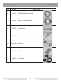
1
www.mkdiamond.com
MK-212 SERIES
OWNERS MANUAL &
OPERATING INSTRUCTIONS
Revision 200
04.2009
Manual Part No. 159862
Caution: Read all safety and operating instructions before
using this equipment. This owners manual MUST accompany
the equipment at all times.
MK Diamond Products, Inc.
MK-212 SAW INTRODUCTION
We at MK Diamond want to congratulate you on selecting the MK-212 saw. We are certain that you will be
pleased with your purchase. MK Diamond takes pride in producing the finest products in the industry.
Operated correctly, your MK-212 saw should provide you with years of quality service. In order to help you,
we have included this manual. This owners manual contains information necessary to operate and maintain
your MK-212 saw safely and correctly. Please take a few minutes to familiarize yourself with the MK-212 Saw
by reading and reviewing this manual.
If you should have questions concerning your MK-212 saw, please feel free to call our friendly customer service
department at: 800 421-5830
Regards,
MK Diamond
NOTE THIS INFORMATION FOR FUTURE USE:
MODEL NUMBER:
SERIAL NUMBER:
PURCHASE PLACE:
PURCHASE DATE:
NOTE: For your (1) one year warranty to be effective, complete the warranty card
(including the Serial Number) and mail it in as soon as possible.
MK-212 SAW TABLE OF CONTENT
SAFETY
Safety Message/Alert Symbols, Warnings
Hazard Symbols
General, Maintenance, Saw Safety
California proposition 65 Message
Electrical Requirements and Grounding Instructions
Lock Out Method
Safety Label Locations
Product Specifications
PRODUCT SPECIFICATIONS
Unpacking
Contents
Transport
SETUP, ADJUSTMENT AND OPERATION
Setup / Assembly
Diamond Blade Installation
90° Cutting Guide Installation
Water Pump Preparation
Pre-start Inspection
External Water Source
Cord Setup
Cutting 90° Straight edge
Angle Cuts
Off-Angle Cuts
MAINTENANCE
Cleanup
Maintenance
Monthly Maintenance
Troubleshooting
EXPLODED VIEW AND PARTS LIST
Exploded View & Part List
THEORY
Theory of Diamond Saws
ACCESSORIES
Accessories
ORDERING AND RETURNING INSTRUCTIONS
Ordering Information
Return Material Policy
Packaging Instructions
Authorized Service Centers
Page
4
5
6-7
8
9-11
11
12
13
14
14
14
15-16
18
19
19
19
20
21-22
22
23
24
25-26
26
27-31
32-34
43
44
45
46
46
46
46
MK-212 SAW SAFETY
Safety precautions should be followed at all times when operating this equipment. Failure to read and
understand the Safety Precaution and Operating Instructions could result in injury to yourself and others.
This Operation and Parts Manual has been developed to provide complete instructions for the safe and
efficient operation of the MK-212 saw.
Before using this machine, ensure that the person operating the machine has read and
understands all instructions in this manual.
SAFETY MESSAGE / ALERT SYMBOLS
A safety message alerts you to potential hazards that could hurt you or others. Each safety message is preceded
by a safety alert symbol (
) and one of three words: DANGER, WARNING, or CAUTION.
DANGER
You WILL be KILLED or SERIOUSLY INJURED if you do not follow directions.
WARNING
You CAN be KILLED or SERIOUSLY INJURED if you do not follow directions.
CAUTION
You CAN be INJURED if you do not follow directions. It may also be used to
alert against unsafe practices.
Each message tells you what the hazard is, what can happen, and what you can do to avoid or reduce injury.
Other important messages are preceded by the word NOTICE.
NOTICE
You can cause PROPERTY DAMAGE to your machine if you don’t follow directions.
The safety labels should be periodically inspected and cleaned by the user to maintain good legibility at a safe
viewing distance. If the label is worn, damaged or illegible, it should be replaced.
MK-212 SAW SAFETY
Potential hazards associated with the MK-212 saw operation will be referenced with Hazard Symbols which
appear throughout this manual, and will be referenced in conjunction with Safety Message/Alert Symbols.
HAZARD SYMBOLS
ALWAYS read this Owner’s Manual before operating the machine.
ALWAYS avoid inhalation of and skin contact with silica dust and/or mist.
ON / OFF
ALWAYS place the power ON/OFF switch in the OFF position when the machine is not in use.
ALWAYS wear approved eye protection.
ALWAYS wear approved respiratory protection.
NEVER operate equipment with covers, or guards removed. Keep fingers, hands, hair and
clothing away from all moving parts to prevent injury.
ALWAYS use caution around gears. Keep fingers, hands, hair and clothing away from all moving
parts to prevent injury.
NEVER touch the power cord with wet hands or while standing in water when it is connected
to a power source.
NEVER operate the machine in an explosive atmosphere or near combustible materials.
MK-212 SAW SAFETY
RULES FOR SAFE OPERATION
DANGER
Failure to follow instructions in this manual may lead to serious injury or even death! This equipment is to
be operated by trained and qualified personnel only! This equipment is for industrial use only.
The following safety guidelines should always be used when operating the MK-212 Saw.
GENERAL SAFETY
• DO NOT operate or service this equipment before reading this entire manual.
• This equipment should not be operated by persons under 18 years of age.
• NEVER operate this equipment without proper protective clothing, shatterproof glasses, steeltoed boots
and other protective devices required by the job.
• NEVER operate this equipment when not feeling well due to fatigue, illness or taking medicine.
• NEVER operate this equipment under the influence of drugs or alcohol.
• Whenever necessary, replace nameplate, operation and safety decals when they become difficult to read.
• ALWAYS check the machine for loose bolts before starting.
• ALWAYS wear proper respiratory (mask) hearing and eye protection equipment when operating this machine.
• ALWAYS store equipment properly when it is not being used. Equipment should be stored in a clean, dry location out of the reach of children.
ON / OFF
• NEVER leave the machine unattended. Turn off electric motor when unattended.
• CAUTION must be observed while servicing the machine. Rotating parts can cause injury if contacted.
• Ensure that any electrical extension cord is protected against damage. Always ensure that the electrical
extension cord is not trapped underneath the machine. When using an extension cord, be sure to use one heavy enough to carry the current your product will draw. An undersized cord will cause a drop in line voltage that will result in a loss of power and overheating. The Table shown on page 9 shows the correct AWG size to use depending on cord length and nameplate ampere rating. If in doubt, use the next heaviest gage. The smaller the gage number, the heavier the cord.
• DO NOT allow extension cord to come into contact with water or fluids.
• DO NOT spray water onto electric motor.
• NEVER operate the machine in an explosive atmosphere.
• Before starting the machine, check that all guards are in position and correctly fitted.
• Keep area around the machine clear of obstructions which could cause persons to fall onto moving parts.
• ALWAYS ensure that the machine is on level ground before using.
• DO NOT overreach. Keep proper footing and balance at all times.
MK-212 SAW SAFETY
• NEVER stand on the tool. Serious injury could occur if a power tool is tipped, or if a cutting tool is
unintentionally contacted.
• Become familiar with the controls of the machine before operating. Know how to stop the machine
quickly in case of emergency.
• ALWAYS secure work. Clamps or a vise should be used to hold work whenever practical. Keeping your
hands free to operate a power tool is safer.
• ALWAYS disconnect AC power plug from power source before moving, cleaning or servicing the
machine.
• NEVER leave a tool running unattended. Do not leave a tool until it comes to a complete stop.
•ALWAYS turn a power tool OFF when leaving the work area, or when a cut is finished.
• Make sure the OFF/ON power switch on the electric motor is always in the OFF position before
inserting the machine’s power plug into an AC receptacle.
• Operate electric motor only at the specified voltage indicated on the nameplate.
• NEVER disconnect any “emergency or safety devices”. These devices are intended for operator safety.
Disconnection of these devices can cause severe injury, bodily harm or even death! Disconnection
of any of these devices will void all warranties.
• Unauthorized equipment modifications will void all warranties. Manufacturer does not assume responsibility
for any accident due to equipment modifications.
• NEVER use accessories or attachments, which are not recommended by MK Diamond for this equipment.
Damage to the equipment and/or injury to user may result.
•Replace damaged cutting blade before operating.
•NEVER try to stop a moving blade with your hand.
•NEVER touch electrical wires or components while the motor is running. Exposed, frayed or worn
electrical motor wiring can be sources of electrical shock that could cause severe injury or burns.
•Keep hands, feet, hair, and clothing away from all moving parts to prevent injury. Never operate a power
tool with covers, shrouds, or guards removed.
WARNING
NEVER use this machine with any cutter designed for wood working.
MAINTENANCE SAFETY
• NEVER lubricate components or attempt service on a running machine.
• Keep the machinery in proper running condition.
• Before using a power tool, check for damaged parts. A guard or any other part that is damaged should be
carefully checked to determine if it would operate properly and perform its intended function. Always
check moving parts for proper alignment or binding. Check for broken parts and mountings and all other
conditions that may affect the operation of the power tool. A guard, or any damaged part, should be
properly repaired or replaced.
SAW SAFETY
WARNING
• Wear eye protection.
• Disconnect saw before servicing, when changing cutting blades and cleaning.
• Use tool only with smooth edge cutting blades free of openings and grooves.
• Replace damaged cutting blade before operation.
• Remove adjusting keys and wrenches.
MK-212 SAW SAFETY
SAFETY WARNINGS
SILICA DUST WARNING
Grinding/cutting/drilling of masonry, concrete, metal and other materials with silica in their composition
may give off dust or mists containing crystalline silica. Silica is a basic component of sand, quartz, brick clay,
granite and numerous other minerals and rocks. Repeated and/or substantial inhalation of airborne crystalline
silica can cause serious or fatal respiratory diseases, including silicosis. In addition, California and some other
authorities have listed respirable crystalline silica as a substance known to cause cancer. When cutting such
materials, always follow respiratory precautions.
CALIFORNIA PROPOSITION 65 MESSAGE
Some dust created by power sanding, sawing, grinding, drilling, and other construction activities contain
chemicals known (to the State of California) to cause cancer, birth defects or other reproductive harm.
Some examples of these chemicals are:
• Lead, from lead-based paints
• Crystalline silica, from bricks and cement and other masonry products
• Arsenic and chromium, from chemically treated lumber
For further information, consult the following sources:
http://www.osha.gov/SLTC/silicacrystalline/index.html
http://www.oehha.org/prop65/out_of_date/6022kLstA.html
Your risk from these exposures varies depending on how often you do this type of work. To reduce your
exposure to these chemicals, work in a well-ventilated area, and work with approved safety equipment,
such as those dust masks that are specially designed to filter out microscopic particles.
MK-212 SAW SAFETY
ELECTRICAL REQUIREMENTS AND GROUNDING INSTRUCTIONS
In order to prevent potential electrical shock and injury, the following electrical safety precautions and symbols should be followed at all times!
WARNING
In case of a malfunction or breakdown, grounding provides a path of least resistance for electric current to
reduce the risk of electric shock. This tool is equipped with an electric cord having an equipment-grounding
conductor and a grounding plug. The plug must be plugged into a matching outlet that is properly installed and
grounded in accordance with all local codes and ordinances.
• Do not modify the plug provided – if it will not fit the outlet; have the proper outlet installed by a
qualified electrician
• Improper connections of the equipment-grounding conductor can result in a risk of electric shock. The equipment-grounding conductor is the insulated conductor that has an outer surface that is green, with or without yellow stripes. If repair or replacement of the electric cord or plug is necessary, do not
connect the equipment-grounding conductor to a live terminal
• Check with a qualified electrician or service personnel if the grounding instructions are not completely understood, or if in doubt as to whether the tool is properly grounded
• Use only 3-wire extension cords that have 3-prong grounding plugs and 3-pole receptacles that accept the tool’s plug
• Repair or replace a damaged or worn cord immediately
WARNING
This tool is intended for use on a circuit that has an outlet that looks like the one shown in Sketch A of
Figure 1. The tool has a grounding plug that looks like the plug illustrated in Sketch A of Figure 1. A temporary adapter, which looks like the adapter illustrated in sketches B and C, may be used to connect this plug to
a 2-pole receptacle as shown in Sketch B, if a properly grounded outlet is not available. The temporary adapter should be used only until a properly grounded outlet can be installed by a qualified electrician. The greencolored rigid ear, lug, and the like, extending from the adapter, must be connected to a permanent ground such
as a properly grounded outlet box.
NOTE: Use of a temporary adapter is not permitted in Canada.
-ETAL3CREW
'ROUNDING
0IN
#OVEROF
'ROUNDED
/UTLET"OX
!
"
!$!04%2
#
'ROUNDING
-EANS
'ROUNDING
0IN
$
Fig. 1 Circuit and Adapter Information
MK-212 SAW SAFETY
WARNING
To reduce the risk of electrocution, keep all connections dry and off the ground.
A Ground Fault Circuit Interrupter (GFCI) should be provided on the circuit(s) or outlet(s) to be used for
this machine. Receptacles are available having built-in GFCI protections and may be used for this measure of
safety.
When using an extension cord, the GFCI should be installed closest to the power source, followed by the
extension cord and lastly, the machine.
WARNING
The pump requires a GFCI. To reduce risk of electric shock when operating the machine with the pump
plugged into the 3-pole receptacle on the motor, connect the saw to a GFCI outlet. See the pump manual and
informational tags enclosed separately for all pump information.
CAUTION
Shock Hazard. For replacement, use only an identical pump, model PE-1 part #151271.
NOTE: Do not run pump dry. Also, be sure to disconnect and remove the pump when cutting dry.
WARNING
To avoid the possibility of the appliance plug or receptacle getting wet, position the machine to one side of
a wall mounted receptacle. This will prevent water from dripping onto the receptacle or plug. A “drip loop,”
shown in Figure 2, should be arranged by the user to properly position the power cord relative to the power source.
The “drip loop” is that part of the cord below the level of the receptacle, or the connector, if an extension
cord is used. This method of positioning the cord prevents the travel of water along the power cord and
coming in contact with the receptacle.
If the plug or receptacle gets wet, DO NOT unplug the cord. Disconnect the fuse or circuit breaker that
supplies power to the tool. Then unplug and examine for presence of water in the receptacle.
Power
Cord
Power
Tool
Supporting
Surface
Receptacle
Drip Loop
Fig. 2 Drip Loop Information
10
MK-212 SAW SAFETY
WARNING
Use only extensions cords that are intended for outdoor use. These extension cords are identified by a
marking “Acceptable for use with outdoor appliances; store indoors while not in use.” Use only extension
cords having an electrical rating not less than the rating of the product. Do not use damaged extension cords.
Examine extension cords before using and replace if damaged. Do not abuse extension cords and do not yank
on any cord to disconnect. Keep cords away from heat and sharp edges. Always disconnect the extension
cord from the receptacle before disconnection the product from the extension cord.
WARNING
To reduce the risk of electrocution, keep all connections dry and off the ground. Do not touch the plug with
wet hands.
WARNING
Use of undersized extension cords result in low voltage to the motor that can result in motor burnout and
premature failure. Barranca Diamond warns that equipment returned to us showing signs of being run in a
low voltage condition, through the use of undersized extension cords will be repaired or replaced totally at
the customers expense. There will be no warranty claim.
To choose the proper extension cord,
•Locate the length of extension cord needed in table provided.
• Once the proper length is found, move down the column to obtain the correct AWG size required for that length of extension cord.
EXTENSION CORD MINIMUM GAGE FOR LENGTH
VOLTS
120v
LOCK OUT METHOD
TOTAL LENGTH OF CORD IN FEET
25 ft.
50 ft.
100 ft.
150 ft.
AWG
AWG
AWG
AWG
18
16
16
14
Table 1
In order to help prevent accidental starting and to help
make your work area “kidproof,” this machine is provided
with a means to deactivate the functioning of the motor
switch. The switch is equipped with a lockout tab that can
be used with a lock to prevent movement of the switch.
With the switch unable to move the motor cannot be
turned on. Removing the lock reactivates the switch.
Fig. 3 Lock Out
11
MK-212 SAW PRODUCT SPECIFICATIONS
SAFETY LABEL LOCATIONS
Safety labels are located according to the table below and the exploded views at the end of this manual. The
labels contain important safety information. Please read the information contained on each safety label. These
labels are considered a permanent part of your saw. If a label comes off or becomes hard to read, contact MK
Diamond or your dealer for a replacement.
Tile Saws
! CAUTION
! WARNING
Receptacle is for
water pump only.
125V, .6 amps max.
Grinding/cutting/drilling of masonry, concrete, metal and other materials with silica in
their composition may give off dust or mists containing crystalline silica. Silica is a basic
component of sand, quartz, brick clay, granite and numerous other minerals and rocks.
Repeated and/or substantial inhalation of airborne crystalline silica can cause serious
or fatal respiratory diseases, including silicosis. In addition,California and some other
authorities have listed respirable crystalline silica as a substance known to cause cancer.
Label A
! CAUTION
This saw is to be used
with a Ground Fault
Circuit Interrupter.
Label B
FOR INFORMATION ON
SERVICE OR
WARRANTY
Label B
Label C
Label F
Label D
! WARNING
For Your Own Safety Read Instruction Manual
Before Operating Saw.
Wear Eye Protection.
Disconnect Saw Before Servicing, when Changing
Cutting Wheels and Cleaning.
Use Tool Only with Smooth Edge Cutting Wheels
Free of Openings and Grooves.
Replace Damaged Cutting Wheel Before Operating.
Do Not Fill Water Bath Above Water Fill Line.
See Manual for Pump Replacement.
Label E
(Not Shown)
Label E
PLEASE CALL
1-800-474-5594
! NOTICE
Label C
Most Motor Problems are caused by improper
voltage and extension cords. Cord should be
one-piece and short as possible. Cord
selection should match the following table.
1-2 H.P.
115v 230v
25’ 100’ Max. Cord Length No. 12 Wire
50’ 150’ Max. Cord Length No. 10 Wire
75’ 250’ Max. Cord Length No. 8 Wire
Label F
Label A
Tile Master Label Sheet Part#166012
Decal/Label
A
B
C
D
E
F
Location
Switch Box
Cutting Head
Cutting Head Arm
Motor - Back
Motor - Back
Motor - Back
Description
Caution - Receptacle is for Water Pump Only
Caution - Use with GFCI only
Service/ Warranty
Warning - Silica Warning
Warning - Read Owners Manual
Notice - Voltage/extension cords
TILE SAW SPECIFIC WARNINGS
WARNING
Wear eye protection.
Use splash guard for every operation for which it can be used.
Disconnect saw before servicing, when changing cutting blades, and cleaning.
Replace damaged cutting blade before operating.
12
Label D
MK-212 SAW PRODUCT SPECIFICATIONS
PRODUCT SPECIFICATIONS
The MK-212 is a versatile Tile and Stone Saw. Operated and used according to this manual, the MK-212 will
provide years of dependable service.
General Description
The MK-212 Tile Saw is engineered as a stand mounted wet tile and stone saw. The saw includes a powerful
115v direct drive AC motor.
Motor Specifications
Motor specifications for the MK-212 are listed in Table 2 below.
MK-212-4
2 hp
120v
14.4
60
3400
226 lbs
Table 2
Horse Power
Voltage
Overall Amperage
Frequency
RPM
Weight
MK-212-6
2 hp
120v
14.4 a / 6.7 a
60
3400
270 lbs
Thermal Overload Protection
The motor is protected by a thermal overload equipped with a manual reset.
Blade Capacity
The MK-212 uses a ten (10) inch (254 mm) diameter wet cutting continuous rim MK Diamond blade.
TILE Types
The MK-212 can cut a variety of tile types including Porcelain, Terra Cotta, Marble, Quarry and Slate, or almost
any other non-ferrous material.
NOTE: The MK-212 is not designed to cut plastic or ferrous (metals) material.
13
MK-212 SAW UNPACKING
UNPACKING
Your MK-212 has been shipped from the factory thoroughly inspected. Only minimal assembly is required.
CAUTION
Use proper lifting techniques when lifting the MK-212.
CONTENTS
In your container, you will find one (1) MK-212 Saw, (4) MK-212 support legs, (1) 10-inch wet cutting continuous rim diamond blade, (1) blade wrench, (1) 90° cutting guide alignment plate, (1) 90° cutting guide, 90° cutting guide hareware, (1) 2-piece protractor (1) drain plug, (1) electric water pump, (1) pump discharge fitting,
(1) cooling transfer tube, (1) flow regulating clamp, (1) 5/16" allen wrench, (1) 5mm allen wrench, (1) owners
manual, (1) pump manual and (1) warranty card.
MK-212 Saw
MK-212
Support Legs
Diamond Blade
Blade Wrench
90° Cutting Guide
Alignment Plate
90° Cutting Guide
90° Cutting Guide
Hardware
2-Piece
Protractor
Drain
Plug
Electric Water
Pump
Pump Discharge
Fitting
Cooling Transfer
Tube
Pump
Manual
Warranty
Card
www.mkdiamond.com
www.mkdiamond.com
MK-212
MK-212 SERIES
SERIES
OWNERS
OWNERS MANUAL
MANUAL &
&
OPERATING
OPERATING INSTRUCTIONS
INSTRUCTIONS
Revision
Revision301
301
04.2009
04.2009
Manual
ManualPart
PartNo.
No.159862
159862
Caution:
Caution:Read
Readallallsafety
safetyand
andoperating
operatinginstructions
instructionsbefore
before
using
usingthis
thisequipment.
equipment.This
Thisowners
ownersmanual
manualMUST
MUSTaccompany
accompany
the
theequipment
equipmentatatallalltimes.
times.
MK
MK Diamond
Diamond Products, Inc.
Flow Regulation
Clamp
5/16" Allen
Wrench
5mm Allen
Wrench
Owner's
Manual
TRANSPORT
1. The MK-212 weighs approximately two hundred and twenty-six (226) pounds and for that reason should not be transported without a minimum of two persons present.
2. Never transport the MK-212 with water in the Water Pan.
Cutting Head
Locked Down
Remove Movable
Cutting Table
Lift Point
NOTE: The Cutting
Head end will be heavier
than the opposite end.
14
MK-212 SAW ASSEMBLY
ASSEMBLY
Follow the assembly instructions to prepare your MK-212 for operation.
Support Leg Installation
(A)
Loosen the Cutting Head
Transverse Knob
(B)
Move the Cutting Head to
one end of the saw
(C)
Tighten the Cutting Head
Transverse Knob
(D)
Obtain the first Leg
(E)
Lift the saw; align the Leg with
the Retaining Slot on the saw
and the install the Leg
(F)
Tighten the Leg Retaining
Wingnut
(G)
Repeat Steps D through F
for the second Leg
(H)
Loosen the Cutting Head
Transverse Knob
(I)
Move the Cutting Head
to the end with the two
installed Legs
15
MK-212 SAW (J)
Tighten the Cutting Head
Transverse Knob
ASSEMBLY
(K)
Install the remaining to Legs
on the opposite side of the
saw using Steps D through G
Diamond Blade Installation
NOTE: When installing the Retaining Screw, do not “cross-thread" and DO NOT over tighten the screw.
(A)
Loosen the Cutting Head
Transverse Knob
(B)
Move the Cutting Head to
one end of the saw
(C)
Tighten the Cutting Head
Transverse Knob
(D)
Loosen the Blade Guard Pivot
Point Retaining Wingnut
(E)
Loosen the Blade Guard
Retaining Knob
(F)
Open the Blade Guard
16
MK-212 SAW (G)
Loosen the Blade Retaining
Nut
(H)
Remove the Blade Retaining
Nut
ASSEMBLY
(I)
Remove the Outer Flange
NOTE:The Diamond Blade will have to be installed onto the MK-212 with the Directional Arrow toward
the motor side of the Cutting Head for the blade to be seated correctly.
(J)
Install Diamond Blade onto
Blade Shaft
(K)
Verify the Directional Arrow
of the Blade matches the
Directional Arrow of the Blade
Guard
(L)
Install the Outer Flange
(M)
Install the Blade Retaining Nut
(N)
Verify the Blade Retaining Nut
is seated in the Outer Flange
(O)
Tighten the Blade Retaining
Nut
17
MK-212 SAW (P)
Close the Blade Guard
(Q)
Tighten the Blade Guard
Retaining Wingnut
ASSEMBLY
(R)
Tighten the Blade Guard
Retaining Knob
90° Cutting Guide Installation
NOTE: Saw comes with A-D installed.
(A)
Using the supplied Hexwrench, loosen and then
remove the two back Cutting
Surface Retaining Screws
(D)
Install two Alignment Plate
Retaining Screws and Flat
Washers through Alignment Plate
and into Support Extensions and
then tighten using the supplied
Hex-wrench
(B)
Install the two 90° Cutting
Guide Support Extension in
place of the Retaining Screws
and tighten using a wrench
(E)
Install the 90° Cutting Guide
onto the Alignment Plate and
tighten the Retaining Knob to
hold the 90° Cutting Guide in
position
18
(C)
Position the 90° Cutting
Guide Alignment Plate over
the Support Extensions
MK-212 SAW SETUP
WATER PUMP PREPARATION
1. To prevent the possibility electrical shock, the MK-212 MUST be de-energized WARNING when preparing the Water Pump for operation.
2. To prevent the possibility of electrical shock, use only MK Diamond qualified
replacement parts
(A)
Install Water Pump Discharge
Fitting
(B)
Press one end of the Cooling
Transfer Tube onto the Water
Pump Discharge Fitting
(C)
Slide Cooling Flow Adjusting
Clamp onto the Cooling
Transfer Tube
PRE-START INSPECTION
Prior to beginning work, a pre-start inspection of the saw should be performed.
(A)
Ensure the ON/OFF Switch is
in the OFF position
(B)
Inspect the Pump Assembly
for damage – ensure the cord
is free of cracks or cuts
(D)
Inspect the MK-212 for
damage – ensure the cord is
free of cracks or cuts
(E)
Verify the Movable Cutting
Head moves freely
19
(C)
Inspect the Diamond Blade for
damage – verify the blade is
correct for the material being
cut
MK-212 SAW SETUP
Water Pump Setup for Operation
The Water Pump can be setup for operation in two ways, External Water Source or Re-circulation.
NOTE: If using a dry blade for operation, DO NOT connect the water pump.
External Water Source
This is the preferred method of cooling.
(A)
Press the free end of the
Cooling Transfer Tube onto
the Blade Guard Cooling Port
(B)
Connect the Water Pump to
the MK-212
(C)
Remove the Drain Plug
(D)
Place the Water Pump in an
external container
(E)
Fill the external container
until water completely covers
the Water Pump suction
(F)
Place an external catch basin
below the Water Basin drain
hole
20
MK-212 SAW SETUP
Re-circulation
NOTE: When using the re-circulation method, the water should be changed often for longer pump life.
(A)
Press the free end of the
Cooling Transfer Tube onto
the Blade Guard Cooling Port
(B)
Connect the Water Pump to
the MK-212
(D)
Place the Water Pump in the
back of the Water Basin
(E)
Fill the Water Basin until
water completely covers the
Water Pump suction
(C)
Ensure the Drain Plug is
installed in the Water Basin
MK-212 Electrical Cord Setup
1. Before connecting the MK-212 to a power supply, be sure the voltage, cycle and CAUTION phase meet the requirements of TABLE 3 below.
VOLTAGE:
CYCLE:
PHASE:
2.
3.
4.
115v
60hz
1-phase Single Phase
Table 3
If using an extension cord, make sure the length and wire gauge correspond to the requirements listed in TABLE 1 on page 11. An extension cord that is too small in wire gauge (diameter), or too long in length, will cause the motor to overheat and could cause premature failure.
Use an approved Ground Fault Circuit Interrupter (GFCI)
Do not cover the motor vents as this could lead to motor overheating.
21
MK-212 SAW OPERATION
NOTE: In order to avoid breaker tripping, a 20 amp circuit breaker should be used.
(A)
Plug MK-212 into the GFCI (A
GFCI should always be used
when operating the MK-212)
(B)
Plug the GFCI into the Power
source
Cutting 90° Straight Edges
CAUTION DO NOT FORCE THE TOOL. It will do the job better and safer at the rate for
which it was designed.
(A)
Position the Adjustable
Cutting Guide to desired cut
length
(B)
Place the tile against the Stop
and Cutting Guide
(C)
Verify the tile is seated against
the Stop and Cutting Guide
(D)
Turn the motor ON
(E)
Verify proper cooling flow on
both sides of the blade
(F)
Perform the cut. Turn the
motor OFF when work is
complete
22
MK-212 SAW OPERATION
Angle Cutting
NOTE: To cut at an angle, the MK-212 has been designed with a pivoting cutting head.
CAUTION DO NOT FORCE THE TOOL. It will do the job better and safer at the rate for
which it was designed.
(A)
Loosen the two Beam Post
Cutting Head Pivot Knobs
located on each end of the saw
(B)
Pivot the Cutting Head and
retighten the two Pivot Knobs
(C)
Position the Adjustable Cutting
Guide to desired cut length
(D)
Place the tile against the Stop
and Cutting Guide
(E)
Verify the tile is seated against
the Stop and Cutting Guide
(F)
Turn the motor ON
(G)
Verify proper cooling flow on
both sides of the blade
(H)
Perform the cut
(I)
Turn the motor OFF when
work is complete
23
MK-212 SAW OPERATION
OFF-Angle Cutting
NOTE: To cut angles other than 90º, a Protractor (MK Diamond Part No. -159572) should be used.
CAUTION DO NOT FORCE THE TOOL. It will do the job better and safer at the rate for
which it was designed.
(A)
Remove the Adjustable
Cutting Guide
(B)
Place the Protractor on the side
of the cutting table. Adjust the
Protractor to fit the tile being cut and
tighten the Retaining Knobs to lock
the Protractor
(C)
Set the desired Cutting Angle
and tighten the Retaining Knob
(D)
Position the tile against the
Protractor and the Stop
(E)
Verify the tile is seated against
the Stop and Protractor
(F)
Turn the motor ON
(G)
Verify proper cooling flow on
both sides of the blade
(H)
Perform the cut
(I)
Turn the motor OFF when
work is complete
24
MK-212 SAW CLEANUP
Cleanup
NOTES: 1. If an external water source was used, steps A through C may be skipped.
2. Dispose of wastewater in accordance with applicable Federal, State and Local laws.
(A)
Clean the Water Pump suction
of all debris
(B)
Place the Water Pump in an
external container
(C)
Run the saw until clear water
is seen at the blade cooling
ports (Approx. 1 minute)
CAUTION Ensure the saw is disconnected before completing the remainder of the cleanup process.
(D)
Ensure the ON/OFF Switch is
in the OFF position
(E)
Unplug the GFCI from the
Power source
(F)
Unplug MK-212 from the
GFCI
(G)
Clean the MK-212 with soap
and clean water
(H)
Drain the Water Basin and
dispose of the water in
accordance with all State,
Local and Federal laws
(I)
Clean the Water Basin
25
MK-212 SAW MAINTENANCE
CAUTION Ensure water is not forced into the motor casing when cleaning.
(J)
Clean the Guide Rail
(K)
Clean the Movable Cutting
Head
(L)
Clean the remainder of the
MK-212
Maintenance Following Use
To extend the life of the MK-212, the following procedure should be performed after each use.
(A)
Ensure the ON/OFF Switch is
in the OFF position
(B)
Unplug MK-212
(D)
Lubricate the Cutting Head
(E)
Lubricate the Cutting Head
springs
26
(C)
Lubricate the Guide Rail
MK-212 SAW MAINTENANCE
Monthly Maintenance
The following maintenance should be performed monthly.
(A)
Remove the Diamond Blade
(B)
Remove the Inner Flange
(C)
Clean the Inner Flange
(D)
Lubricate the Inner Flange
Gasket
(E)
Clean the Blade Shaft
(F)
Lubricate the Blade Shaft
(G)
Reinstall the Inner Flange and
Blade
27
MK-212 SAW MAINTENANCE
Flow Adjustment
NOTE: If flow to the diamond blade requires adjustment, perform the following actions.
(A)
Increase cooling flow by
releasing the Flow Adjusting
Clamp
(B)
Reduce cooling flow by
pressing down on the Flow
Adjusting Clamp
Diamond Blade Change-out
NOTE: When installing the Retaining Nut do not “cross-thread" and DO NOT over tighten the screw.
(A)
Loosen the Cutting Head
Transverse Knob
(B)
Move the Cutting Head to
one end of the saw
(C)
Tighten the Cutting Head
Transverse Knob
(D)
Loosen the Blade Guard Pivot
Point Retaining Wingnut
(E)
Loosen the Blade Guard
Retaining Knob
(F)
Open the Blade Guard
28
MK-212 SAW MAINTENANCE
Diamond Blade Change-out
NOTE: When installing the Retaining Nut do not “cross-thread" and DO NOT over tighten the screw.
(G)
Loosen and remove the Blade
Retaining Nut
(H)
Remove the Outer Flange
(I)
Remove the old Diamond
Blade
NOTE: The Diamond Blade will have to be installed onto the MK-212 with the Directional Arrow toward
the motor side of the Cutting Head for the blade to be seated correctly.
(J)
Install the new Diamond Blade
onto the Blade Shaft
(K)
Verify the Directional Arrow
of the Blade matches the
Directional Arrow of the Blade
Guard
(L)
Install the Outer Flange
(M)
Install the Blade Retaining Nut
(N)
Verify the Blade Retaining Nut
is seated in the Outer Flange
(O)
Tighten the Blade Retaining
Nut
29
MK-212 SAW (P)
Close the Blade Guard
(Q)
Tighten the Blade Guard
Retaining Knob
MAINTENANCE
(R)
Tighten the Blade Guard
Pivot Point Retaining
Wingnut
Table Removal
NOTE: The Rubber topped cutting table may be removed to replace the rubberized surface or to clean the
Water Basin.
(A)
Remove the Adjustable Cutting
Guide
(B)
Remove the 90° Cutting Guide
Alignment Plate
(D)
Remove all Retaining Screws
using the Hex Wrench provided
with the MK-212
(E)
Remove table Cutting
Surface pieces
30
(C)
Locate the six table Retaining
Screws on both sides of the
cutting surface
(F)
Clean the Water Basin
MK-212 SAW MAINTENANCE
(G)
Reinstall all components
removed in steps A through E
Cutting Head Alignment
NOTE: The alignment of the Cutting Head should be checked periodically to ensure the accuracy of the cut.
(A)
Remove the Blade Guard
(B)
Using a combination square,
check the Blade for vertical
alignment
(C)
Loosen the two Beam Post
Cutting Head Pivot Knobs
located on each end of the saw
(D)
Pivot the Beam and retighten
the two Pivot Knobs
(E)
Using a combination square,
check the Blade for 45°
alignment
(F)
Loosen the four Guide Rail
Adjusting Screws using a
1/2-inch socket
31
MK-212 SAW (G)
Adjust the Guide Rail until it
is aligned both vertically and
horizontally
MAINTENANCE
(H)
Tighten the four Guide Rail
Adjusting Screws using a
1/2-inch socket
troubleshooting
Blade will not cut properly
(A)
Check for Smoothness or
“Glazing” (Dress blade if
needed)
(B)
Check for proper rotation
(D)
Verify the blade is correct for
the material being used.
32
(C)
Ensure the Blade Core is not
bent and Arbor is not out of
round
MK-212 SAW MAINTENANCE
Cooling Flow
(A)
Verify the cooling flow
Adjusting Clamp is open
(B)
Remove the Cooling Transfer
Tube from the Blade Guard
inlet
(C)
Place Pump into a bucket of
water and check flow
(D)
Remove the Cooling Transfer
Tube and check for flow
(E)
Remove the Pump Discharge
Fitting and check for flow
(F)
Remove the Pump Intake
Screen and check for debris –
clean the screen if necessary
NOTE:“Rodding” cooling channels is performed by inserting a small wire rod through the cooling inlet on
top of the Blade Guard and directing the rod out through each of the cooling flow tubes located on the
underside of the Blade Guard. The cooling channels should be “rodded” until all ports are free of foreign
debris.
(G)
Rod (clean out) the Cooling
Manifold and then recheck flow.
33
MK-212 SAW MAINTENANCE
Cutting Head Does Not Move Correctly
(A)
Check that Guide Rail and
Cutting Head is clean and
clean if dirty
(B)
Lubricate the Guide Rail and
Cutting Head
(C)
Check the Cutting Head
alignment.
(A)
Check the ON/OFF Switch is
in the ON position
(B)
Verify all plugs are fully
connected
(C)
Check to see if the Ground
Fault Circuit Interrupter
(GFCI) tripped
(D)
Verify the circuit breaker is at
least 20 amps – if not, move
to 20 amp circuit
(E)
Verify circuit breaker not
tripped; if it is tripped, reset it
once only
(F)
Check power source voltage
is 115v – if not 115v, move to
another circuit.
Blade Stops Turning
34
NOTES
35
PART LISTS
Part# 159414
MK-212-4 SAW 36
MK-212-4 SAW PART LISTS
ITEM
NO.
DESCRIPTION
PART OR
IDENTIFYING
NO.
QTY.
REQ.
1
NUT, 3/8-6 HEX
101188
4
2
NUT, HEX, 5/16 - 18
101196
2
3
FITTING, PLASTIC, 1/4 FNPT X 1/4 BARB
128397
1
4
HOSE,VINYL, 3/8 X 1/4
132951
1
5
SCREW, 5/16 - 18 X 1-3/4 HEX HEAD CAP
150919
4
6
WASHER, 3/8 SAE FLAT
150923
15
7
WASHER, 3/8 SPLIT LOCK
150925
12
8
SCREW, PAN HD SELF TPIO-24 X 3/8
151262
1
9
BOLT, HEX HEAD 1/4 20 X 3/4"
151267
4
10
PUMP, WATER 115V/60HZ UL/CSA
151271
1
11
SCREW, 5/16 - 18 X 1 HEX HEAD MACHINE
151743
4
12
KNOB, 5/16-18 NYLOK
151681
1
13
SCREW, 5/16 -18 X 1 HEX HEAD MACHINE
151743
4
14
WINGNUT, 5/16 - 18 NYLOK
151746
1
15
WASHER, LOCK, SPLIT, 5/16
151747
10
16
WASHER, 5/16 SAE FLAT
151754
8
17
SCREW, WING, 1/4 - 20 X 1/2
151888
1
18
WASHER, 1/4 SAE FLAT
151915
13
19
WASHER, 1/4 SPLIT LOCK
152591
4
20
SCREW, 1/4 - 20 X 1/2 HEX HEAD
152608
8
21
CSTUD, 5/16 - 18 X 1-1/2"
153680
1
22
SCREW, PHILP SELF TAP 10 - 24 X 5/8"
153681
1
23
F.H.C.S. 3/8 - 16 X 1"
154019
4
24
LABEL, 1-3/4 X 5 MK LOGO
154335
2
25
CLAMP, HOSE 1/2 - 3/4
154394
1
26
SCREW, 1/4 - 20 X 3/4 FLAT HEAD PHILLIPS MACHINE
154657
4
27
LEG
155397
4
28
SCREW, THUMB 3/8 - 16 X 3/4"
155398
4
29
BLADE, 10" TILE
155619
1
30
LABEL, SAFETY
155806
1
31
SCREW, SHLDR, SOC HD, 1/2 X 3/4
156177
2
32
SCREW, SOCKET HEAD CAP 3/8 - 16 X
156602
1
33
KNOB, TRI
156770-02
2
34
TAG, SERIAL #, BLANK
157500-RW
1
35
DRIVE SCREW, #7 X 5/16 ROUND HEAD
157849
2
37
PART LISTS
Part# 159414
MK-212-4 SAW 38
MK-212 SAW PART LISTS
ITEM
NO.
DESCRIPTION
PART OR
IDENTIFYING
NO.
QTY.
REQ.
36
GUARD, BLADE
159416
1
37
POST, PIVOT (COMP)
159418
2
38
FRAME, PAN WELDMENT
159419
4
39
TABLE ASSEMBLY
159420
2
40
GUARD, INNER BLADE (COMP)
159423
1
41
PROTRACTOR ASSEMBLY
159572
1
42
BLOCK, RAIL
159622
2
43
RAIL, 2 X 2 X 50
159641
1
44
MOUNT, SOGA MOTOR
159642
1
45
CUTTING HEAD
159853
1
46
MANIFOLD, WATER
159854
1
47
STOP, RUBBER BUMPER
159855
2
48
SCREW, SET UP 3/8 - 16 X 1/2"
159856
2
49
PLUG, 2-1/2 DIA RUBBER
159858
1
50
KEY, MOTOR MOUNT
159859
2
51
OWNERS MANUAL
159862
1
52
NUT, 3/8 - 16 HEX
159863
1
53
FOOT, RUBBER
159977
4
54
WRENCH, 30MM OPEN END, 30DEG
159978
1
55
WRENCH, 5MM ALLEN
159979
1
56
STAND OFF, BACK STOP
160117
2
57
ASSEMBLY, RIP GUIDE
160288
1
58
GUARD, SPLASH
160310
1
59
LABEL, MK-212
160669
2
60
SWITCH BOX
160687
1
61
2 H.P. SOGA 115V MOTOR
162078
1
62
STOP, BACK
165685
1
63
MAT, TABLE
166418
4
64
TAPE,VHB 5952 3M
166487
1
65
PRIMER, 3M 23926
166488
1
66
BRACKET, POST MOUNT
167376
1
67
BRACKET, HEAD MOUNT
167377
1
68
CARRIER, CABLE
167430
1
69
WRENCH, 5/16" ALLEN
167679
1
39
PART LISTS
Part# 165652
MK-212-6 SAW 40
MK-212-6 SAW PART LISTS
ITEM
NO.
DESCRIPTION
PART OR
IDENTIFYING
NO.
QTY.
REQ.
1
NUT, 3/8 - 16 HEX
101188
4
2
NUT, HEX, 5/16 - 18
101196
2
3
FITTING, PLASTIC, 1/4 FNPT X 1/4 BARB
128397
1
4
HOSE,VINYL, 3/8 X 1/4
132951
1
5
SCREW, 5/16 - 18 X 1-3/4 HEX HEAD CAP
150919
4
6
WASHER, 3/8 SAE FLAT
150923
15
7
WASHER, 3/8 SPLIT LOCK
150925
12
8
SCREW, PAN HD SELF TP10-24 X 3/8
151262
1
9
BOLT, HEX HEAD 1/4 - 20 X 3/4"
151267
4
10
PUMP, WATER 115V/60HZ UL/CSA
151271
1
11
SCREW, 5/16 -18 X 3/4 HEX HEAD MACHINE
151369
2
12
KNOB, 5/16 -18 X 1
151681
1
13
SCREW, 5/16 -18 X 1 HEX HEAD MACHINE
151743
4
14
WINGNUT, 5/16 -18 NYLOK
151746
1
15
WASHER, LOCK, SPLIT, 5/16
151747
10
16
WASHER, 5/16 SAE FLAT
151754
8
17
SCREW, WING, 1/4 - 20 X 1/2
151888
1
18
WASHER, 1/4 SAE FLAT
151915
14 T
19
WASHER, 1/4 SPLIT LOCK
152591
4
20
SCREW, 1/4 - 20 X 1/2 HEX HEAD
152608
8
21
STUD, 5/16 - 18 X 1-1/2"
152608
1
22
SCREW, PHILP SELF TAP 10 - 24 X 5/8"
153681
1
23
F.H.C.S. 3/8 - 16 X 1"
154019
4
24
LABEL, 1-3/4 X 5 MK LOGO
154335
2
25
CLAMP, HOSE 1/2 - 3/4
154394
1
26
SCREW, 1/4 - 20 X 3/4 FLAT HEAD PHILLIPS MACHINE
154657
4
27
LEG
155397
4
28
SCREW, THUMB 3/8 - 16 X 3/4"
155398
4
29
BLADE, 10" TILE
155619
1
30
LABEL, SAFETY
155806
1
31
SCREW, SHLDR, SOC HD, 1/2 X 3/4
156177
2
32
SCREW, SOCKET HEAD CAP 3/8 - 16 X 1
156602
12
33
KNOB, TRI
156770-02
2
34
TAG, SERIAL #, BLANK
157500-RW
1
35
DRIVE SCREW, #7 X 5/16 ROUND HEAD
157849
2
41
PART LISTS
Part# 165652
MK-212-6 SAW 42
MK-212-6 SAW PART LISTS
ITEM
NO.
DESCRIPTION
PART OR
IDENTIFYING
NO.
QTY.
REQ.
36
GUARD, BLADE
159416
1
37
POST, PIVOT (COMP)
159418
2
38
TABLE ASSEMBLY
159420
3
39
GUARD, INNER BLADE (COMP)
159423
1
40
KNOB, 1/4 - 20 X 1 - 1/4
159428-2
1
41
PROTACTOR ASSEMBLY
159572
1
42
BLOCK, RAIL
159622
2
43
MOUNT, SOGA MOTOR
159642
1
44
CUTTING HEAD
159853
1
45
MANIFOLD, WATER
159854
1
46
STOP, RUBBER BUMPER
159855
2
47
SCREW, SET UP 3/8 - 16 X 1/2"
159856
2
48
PLUG, 2-1/2 DIA RUBBER
159858
1
49
KEY, MOTOR MOUNT
159859
2
50
OWNER MANUAL
159862
1
51
NUT, 3/8 - 16 HEX
159863
1
52
FOOT, RUBBER
159977
4
53
WRENCH, 30MM OPEN END, 30DEG
159978
1
54
WRENCH, 5MM ALLEN
159979
1
55
STAND OFF, BACK STOP
160117
2
56
GUIDE, 15 INCH RIP (COMP)
160286
1
57
PLATE, PRESSURE
160287
1
58
GUARD, SPLASH
160310
1
59
SWITCH BOX
160687
1
60
MOTOR, 115V, 2HP SOGA
162078
1
61
RAIL, 2 X 2 X 50
165651
1
62
STOP, BACK
165685
1
63
LABEL, MK212-6
165928
2
64
MAT, TABLE
166418
4
65
TAPE,VHB 5952 3M
166487
1
66
PRIMER, 3M 23926
166488
1
67
PAN WELDMENT
166547
1
68
BRACKET, POST MOUNT
167376
1
69
BRACKET, HEAD MOUNT
167377
1
70
CARRIER, CABLE
167431
1
71
WRENCH, 5/16" ALLEN
167679
1
43
MK-212 SAW THEORY
THEORY OF DIAMOND BLADES
Diamond blades do not really cut; they grind the material through friction. Diamond crystals, often visible at
the leading edge and sides of the rim/segment, remove material by scratching out particles of hard, dense materials, or by knocking out larger particles of loosely bonded abrasive material. This process eventually cracks
or fractures the diamond particle, breaking it down into smaller pieces. As a result, a diamond blade for cutting
soft, abrasive material must have a hard metal matrix composition to resist this erosion long enough for the
exposed diamonds to be properly utilized. Conversely, a blade for cutting a hard, non-abrasive material must
have a soft bond to ensure that it will erode and expose the diamonds embedded in the matrix. These simple
principles are the foundation of “controlled bond erosion.”
Types of Cutting
There are two basic types of cutting-Dry or Wet. The choice of which type of blade to use depends on:
• The requirements of the job
• The machine/tool utilizing the diamond blade
• The preference of the operator
In the case of DRY cutting, the overwhelming popularity and quantity of hand-held saws and the flexible nature
of MK Diamond blades to professionally handle most ceramic, masonry, stone and concrete materials, make the
DRY cutting blade a very attractive tool. When using a DRY blade, the user must be aware of distinct operating practices to ensure optimum performance. DRY cutting blades require sufficient airflow about the blade to
prevent overheating of the steel core. This is the best accomplished by shallow, intermittent cuts of the material with periods of “free-spinning” (for several seconds) between each cut, to maximize the cooling process.
For WET cutting applications, MK has the exact blade to compliment both the material to be cut and the wet
cutting machine to be used. During cutting operations, liberal amounts of water act as a coolant to support the
cutting effectiveness and longevity of the WET blade. Additionally, using water adds to the overall safety of cutting operations by keeping the dust signature down.
Know All You Can About the Material You Wish to Cut
44
MK-212 SAW ACCESSORIES
ITEM
NUMBER
DESCRIPTION
1.
Various
MK-275, Marble Profile Wheel
2.
155619
MK-415, 10" Diamond Blade
3.
152792
Dressing Stone
4.
152610
Ground Fault Circuit Interrupter
5.
See Catalog
Protractor
6.
165884
Side Table
7.
166271
Foot Switch
45
ORDERING INFORMATION
You may order MK Diamond products through your local MK Diamond distributor or, you may order direct
from MK Diamond.
NOTE: There is a $25.00 minimum order when ordering direct from MK Diamond. All purchases must be
made using VISA, MasterCard or American Express.
When
•
•
•
•
•
ordering direct from MK Diamond, please have the following information ready before calling:
The Model Number of the saw
The Serial Number of the saw
Where the saw was purchased and when
The Part Number for the part(s) being ordered
The Part Description for the part(s) being ordered
All parts may be ordered by calling toll free to – 800 421-5830 or 310 539-5221 and asking for Customer
Service. For technical questions, call – 800 474-5594.
RETURN MATERIALS POLICY
To expedite the service relative to the return of a product purchased through MK Diamond, please
observe the following:
NOTE: When returning all items, they must have been purchased within the previous twelve (12)
months.
• Have the Model Number of the saw
• Have the Serial Number of the saw
• Have the location of where the saw was purchased
• Have the date when the saw was purchased
• Contact Customer Service for approval to return the item(s)
• Obtain a Returned Goods Number (RGA) authorizing the return
• Follow the packaging instructions in the following section
• Ensure your item(s) are prepaid to the destination
For returned items, call toll free to – 800 421-5830 or 310 539-5221 and ask for Customer Service.
For technical questions, call – 800 474-5594 or 310 257-2845.
PACKAGING INSTRUCTIONS
• Remove the Blade guard and Support Angle Assembly
• Dry the saw before shipping
• When packing, include the following: MK-212 saw, Diamond Blade, Blade guard and Support Angle
Assembly and Adjustable Cutting Guide (Other Accessories are not required)
• Package the unit in its original container or one of comparable size (do not ship the unit partially
exposed)
• Ensure all parts are secured in the packaging to prevent moving
AUTHORIZED SERVICE CENTERS
For quicker repair time, you may contact MK Diamond Customer Service, toll free, at 800 421-5830 or 310
539-5221 for the Authorized Service Center closest too you or visit our web site at www.mkdiamond.com.
For technical questions, call – 800 474-5594.
46
MK-212 Series Saw
OWNERS MANUAL & OPERATING INSTRUCTIONS
DOCUMENT NO. 159862
MK Diamond Products, Inc.
1315 Storm Parkway
Torrance, CA 90501
Toll-Free: (800) 845-3729
Phone: (310) 539-2221
Fax: (310) 539-5158
www.mkdiamond.com
47