1
S25P Quick Reference
Version 2.5.2.0
October 2007
101-00244-02
Copyright 2007 Force10 Networks
All rights reserved. Printed in the USA, October 2007.
Force10 Networks reserves the right to change, modify, revise this publication without notice.
Trademarks
Copyright 2007 by Force10 Networks, Inc. All rights reserved. Force10 Networks® and E-Series® are registered trademarks of Force10
Networks, Inc. Force10, the Force10 logo, E1200, E600, E300, EtherScale, FTOS, S-Series, SFTOS, and TeraScale are trademarks of
Force10 Networks, Inc. All other brand and product names are registered trademarks or trademarks of their respective holders.
Statement of Conditions
In the interest of improving internal design, operational function, and/or reliability, Force10 Networks reserves the right to make changes to
products described in this document without notice.
USA Federal Communications Commission (FCC) Statement
This equipment has been tested and found to comply with the limits for a Class A digital device, pursuant to Part 15 of the FCC rules. These
limits are designated to provide reasonable protection against harmful interference when the equipment is operated in a commercial
environment. This equipment generates, uses, and can radiate radio frequency energy. If it is not installed and used in accordance to the
instructions, it may cause harmful interference to radio communications. Operation of this equipment in a residential area is likely to cause
harmful interference, in which case users will be required to take whatever measures necessary to correct the interference at their own expense.
Properly shielded and grounded cables and connectors must be used in order to meet FCC emission limits. Force10 Networks is not
responsible for any radio or television interference caused by using other than recommended cables and connectors or by unauthorized
changes or modifications in the equipment. Unauthorized changes or modification could void the user’s authority to operate the equipment.
This device complies with Part 15 of the FCC Rules. Operation is subject to the following two conditions: (1) this device may not cause
harmful interference, and (2) this device must accept any interference received, including interference that may cause undesired operation.
Canadian Department of Communication Statement
The digital apparatus does not exceed the Class A limits for radio noise emissions from digital apparatus set out in the Radio Interference
Regulations of the Canadian Department of Communications.
Attention: Le present appareil numerique n’ emet pas de perturbations radioelectriques depassant les normes applicables aux appareils
numeriques de la Class A prescrites dans le Reglement sur les interferences radioelectriques etabli par le ministere des Communications du
Canada.
European Union EMC Directive Conformance Statement
This product is in conformity with the protection requirements of EU Council Directive 89/336/EEC on the approximation of the laws of the
Member States relating to electromagnetic compatibility. Force 10 Networks can not accept responsibility for any failure to satisfy the
protection requirements resulting from a non-recommended modification of this product, including the fitting of non-Force10 option cards.
This product has been tested and found to comply with the limits for Class A Information Technology Equipment according to CISPR 22/
European Standard EN 55022. The limits for Class A equipment were derived for commercial and industrial environments to provide
reasonable protection against interference with licensed communication equipment.
Warning: This device is a Class A product. In a domestic environment, this device can cause radio interference, in
which case, the user may be required to take appropriate measures.
VCCI Compliance for Class A Equipment (Japan)
This is Class A product based on the standard of the Voluntary Control Council For Interference by Information Technology Equipment
(VCCI). If this equipment is used in a domestic environment, radio disturbance may arise. When such trouble occurs, the user may be
required to take corrective actions.\
Danger: AC Power cords are for use with Force10 Networks equipment only, do not use Force10 Networks AC Power
cords with any unauthorized hardware.
Contents
Overview . . . . . . . . . . . . . . . . . . . . . . . . . . . . . . . . . . . . . . . . . . . . . . . . . . . . . . . . . . . . . . . . . . . . . . . 4
Contents of the S-Series Documentation CD-ROM . . . . . . . . . . . . . . . . . . . . . . . . . . . . . . . . . . . . . . . 5
Installing the Hardware . . . . . . . . . . . . . . . . . . . . . . . . . . . . . . . . . . . . . . . . . . . . . . . . . . . . . . . . . . . . 6
Component Overview . . . . . . . . . . . . . . . . . . . . . . . . . . . . . . . . . . . . . . . . . . . . . . . . . . . . . . . . . . 6
Inserting 10-Gigabit and Stacking Modules (optional) . . . . . . . . . . . . . . . . . . . . . . . . . . . . . . . . . . 6
Attaching the S25P to the Rack . . . . . . . . . . . . . . . . . . . . . . . . . . . . . . . . . . . . . . . . . . . . . . . . . . 8
Connecting Stacking Ports (optional) . . . . . . . . . . . . . . . . . . . . . . . . . . . . . . . . . . . . . . . . . . . . . . 9
Supplying Power . . . . . . . . . . . . . . . . . . . . . . . . . . . . . . . . . . . . . . . . . . . . . . . . . . . . . . . . . . . . . 10
S25P-DC . . . . . . . . . . . . . . . . . . . . . . . . . . . . . . . . . . . . . . . . . . . . . . . . . . . . . . . . . . . . . . . . . . 10
Installing SFP Transceivers (optional) . . . . . . . . . . . . . . . . . . . . . . . . . . . . . . . . . . . . . . . . . . . . .11
Installing XFP Transceivers (optional) . . . . . . . . . . . . . . . . . . . . . . . . . . . . . . . . . . . . . . . . . . . . . .11
Connecting to the Console Port . . . . . . . . . . . . . . . . . . . . . . . . . . . . . . . . . . . . . . . . . . . . . . . . . 12
Basic Software Configuration . . . . . . . . . . . . . . . . . . . . . . . . . . . . . . . . . . . . . . . . . . . . . . . . . . . . . . 12
Creating a User and Password . . . . . . . . . . . . . . . . . . . . . . . . . . . . . . . . . . . . . . . . . . . . . . . . . . 13
Setting the Enable Password . . . . . . . . . . . . . . . . . . . . . . . . . . . . . . . . . . . . . . . . . . . . . . . . . . . 13
Enabling Ports . . . . . . . . . . . . . . . . . . . . . . . . . . . . . . . . . . . . . . . . . . . . . . . . . . . . . . . . . . . . . . . 13
Setting the Management IP Address . . . . . . . . . . . . . . . . . . . . . . . . . . . . . . . . . . . . . . . . . . . . . 14
Enabling Telnet to the Switch . . . . . . . . . . . . . . . . . . . . . . . . . . . . . . . . . . . . . . . . . . . . . . . . . . . 14
Managing a Stack of S-Series Switches . . . . . . . . . . . . . . . . . . . . . . . . . . . . . . . . . . . . . . . . . . . 14
Installing New Software . . . . . . . . . . . . . . . . . . . . . . . . . . . . . . . . . . . . . . . . . . . . . . . . . . . . . . . . 15
Creating a Simple Configuration using VLANs and STP . . . . . . . . . . . . . . . . . . . . . . . . . . . . . . 15
Enabling Spanning Tree Protocol . . . . . . . . . . . . . . . . . . . . . . . . . . . . . . . . . . . . . . . . . . . . . . . . 16
Notable Differences between FTOS and SFTOS . . . . . . . . . . . . . . . . . . . . . . . . . . . . . . . . . . . . . . . 16
Interface Nomenclature . . . . . . . . . . . . . . . . . . . . . . . . . . . . . . . . . . . . . . . . . . . . . . . . . . . . . . . . 17
The iSupport Website . . . . . . . . . . . . . . . . . . . . . . . . . . . . . . . . . . . . . . . . . . . . . . . . . . . . . . . . . . . . 18
S25P Quick Reference
3
Overview
Thank you for purchasing a Force10 Networks switch!
This S25P Quick Reference document is printed and included in the S25P shipping box to provide you with
a quick way to access basic installation and configuration instructions and to tell you how to get more
information.
In addition to the S25P with its SFTOS operating system loaded in its default configuration, the shipping
box also contains two AC power cords, a DB9-to-RJ45 connector, and a small bag with rack-mounting
screws, plastic feet for table-top mounting, and the S-Series Documentation CD-ROM (hereafter simply
referred to as the “S-Series CD-ROM”). Other purchased components are shipped separately.
The hardware installation section (Installing the Hardware on page 6) in this guide contains a subset of the
information in Installing the S25P System, a book stored as a PDF both on the S-Series CD-ROM and at
the iSupport website.
The software configuration section here (see Basic Software Configuration on page 12) contains a subset
of the configuration information in the SFTOS Configuration Guide, which is also on the S-Series
CD-ROM and at the iSupport website.
In fact, all of the S-Series documentation that is on the S-Series CD-ROM is also available on the iSupport
website.
For more information about the S-Series CD-ROM, see the next section, Contents of the S-Series
Documentation CD-ROM on page 5.
For more information about the iSupport website (login required), see The iSupport Website on page 18.
Note: This S25P Quick Reference is specific to SFTOS Version 2.5.1 for the S25P.
4
Overview
Contents of the S-Series Documentation CD-ROM
The S-Series Documentation CD-ROM launches a Web page from the CD-ROM containing the links
described in the following sections:
Force10 Literature: This is a link to the Force10 Literature folder on the CD-ROM. It contains links to
data sheets for all Force10 products.
Installing S50N and S50V Systems: This book contains details of installation options for the S50N
(including S50N-DC) and S50V models.
S50N and S50V Quick Reference for SFTOS 2.5.2: This is a PDF version of the book in the shipping box.
Installing the S50 System: This book contains details of installation options for the S50 model.
S50 Quick Reference for SFTOS 2.5.1: This is a PDF version of the book that is included in the S50
shipping box.
Installing the S25P System: This book contains details of installation options for the S25P model.
S25P Quick Reference for SFTOS 2.5.1.0: This book is a PDF version of this book, which is included in the
S25P shipping box.
SFTOS Command Reference: This book contains syntax statements for all SFTOS commands in both the
Layer 2 and Layer 3 packages.
SFTOS Configuration Guide: This book is designed to help you perform the most common configuration
tasks, with examples of the most commonly used commands.
MIBs: This is a link to a folder on the CD-ROM containing the S-Series MIBs, updated for SFTOS 2.5.2.
Secure Communications (SSH/SSL/HTTPS): This link opens an HTML page containing a link to the
S-Series Secure Management application note on the CD, describing how to enable secure communications
through SSH, SSL, and HTTP. The page also contains links to folders on the CD-ROM containing example
keys and shell scripts that you can use to generate your own SSH keys and SSL certificates.
The Training Material link on the CD-ROM home page is to a folder on the CD-ROM containing sets of
slides, in PDF format, that are used in the S-Series training, updated for SFTOS 2.5.2.
Note: The SFTOS software and the S-Series Release Notes, which had been on previous
versions of the S-Series CD-ROM, are no longer on the CD-ROM. The iSupport website of
Force10 contains the most recent software and documents. For details, see The iSupport Website
on page 19.
Note: Documentation for the S2410 models is on the S2410 Documentation CD-ROM.
S50N and S50V Quick Reference
5
Installing the Hardware
Danger: To prevent electrical shock, make sure the S25P is grounded properly. If you do not
ground your equipment correctly, excessive emissions may result.
To install the S25P system, Force10 Networks recommends that you complete the installation procedures
in the order presented below, before attaching a power source:
•
•
•
•
•
Insert 10-Gigabit and Stacking Modules (optional). See Inserting 10-Gigabit and Stacking Modules
(optional) on page 6.
Attach the S25P to the Rack. See Attaching the S25P to the Rack on page 8.
Connect Stacking Ports (optional). See Connecting Stacking Ports (optional) on page 9.
Connect to the Console Port. See Connecting to the Console Port on page 12.
Connect Ethernet Ports. See Enabling Ports on page 13. .
Warning: As with all electrical devices of this type, take all the necessary safety precautions to prevent
injury when installing this system. Electrostatic discharge (ESD) damage can occur if components are
mishandled. Always wear an ESD-preventive wrist or heel ground strap when handling the switch and its
components.
Warning: Before starting the installation, be sure that the installation conditions conform to those
specified in Installing the S25P System.
Component Overview
The following sections in this S25P Quick Reference contain basic information on several optional
modules. For more on the components of the S25P, see Installing the S25P System, on the S-Series
CD-ROM.
To manage the switch, you first access the S25P through its console port (see Connecting to the Console
Port on page 12), where you use the SFTOS Command Line Interface (CLI) to enable ports (see Enabling
Ports on page 13.) All ports are in the management VLAN by default, so you can access the CLI through
any active ports (see Basic Software Configuration on page 12.)
Inserting 10-Gigabit and Stacking Modules (optional)
The S25P has two expansion slots in the back of the chassis. There are four types of module available:
•
•
Two types of stacking module: 12 Gbps (two ports) and 24 Gbps (one port)
Two types of 10-Gigabit module: fiber (optical) and copper (10GBase-CX4)
The system supports interoperability of the modules, in any combination of slots, although connecting all
four ports of two 12G stacking modules is not supported, nor is connecting one kind of stack port to
anything other than the same kind of stack port. For the 10-Gigabit modules, the system numbers the ports
25 and 26 in the left-hand slot and 27 through 28 in the right-hand slot as you face the front of the switch.
So, for clarity in the use of the CLI in port assignment, if you are only using one XFP or CX4 module,
insert it in the left-most expansion slot.
6
Installing the Hardware
To install a module, follow the steps below:
Step
1.
Task
If the switch is on, save the running config, if desired (and different from the startup configuration),
with the command write memory. Then power off the switch by pulling its power cable.
Caution: Removing a module from a running switch will crash and lock up the switch, requiring a
power cycle. While you can insert a module into the switch without a problem, the module will not be
usable until after a reboot.
Use a #2 Phillips screwdriver to remove either the module faceplate or an existing module. Note that
these slots, when used for 10G Ethernet ports, assign port-numbering from left to right as you face
the front of the switch. So, for clarity in programming ports, you might favor using the left-most slot for
the first 10G module.
3.
Grasping the module faceplate, remove the module from its packaging and slide it into the slot until
the module faceplate is flush with the switch.
4.
Secure the captive screws on either side of the module.
5.
The optical XFP 10-Gigabit module (Catalog # S50-01-10GE-2P) requires additional XFP transceiver
inserts, which are not included in the module kit (see Installing XFP Transceivers (optional) on
page 11 or the installation instructions that come with the transceiver). The ports in the copper CX4
module (Cat # S50-01-10GE-2C) do not require inserts.
fn00144s25P
2.
If you are installing a CX4 module, and you are connecting the ports with a cable substantially shorter
or longer than 5m, use the cx4-cable-length command to set the signal strength. Use
cx4-cable-length long for a longer cable, cx4-cable-length short for a shorter cable. See the
System Management Commands chapter in the SFTOS Command Reference for details.
Note: Take care not to connect CX4 ports to 12G stack ports in the S50V and S25P. The receptacles
and cables are the same, but they are incompatible. CX4 ports are labeled as such; stack ports are
not labeled. You can order several cable lengths of each type; they are not part of this kit.
For details on enabling ports, see Enabling Ports on page 13 or the SFTOS Configuration Guide.
S25P Quick Reference
7
Attaching the S25P to the Rack
Warning: As with all electrical devices of this type, take all necessary safety precautions to prevent injury
when installing the system. Electrostatic discharge (ESD) damage can occur if components are
mishandled. Always wear an ESD-preventive wrist or heel ground strap when handling the switch and its
components.
Warning: For fan maintenance and proper ventilation, position the switch in an equipment rack (or
cabinet) with a minimum of five inches (12.7 cm) of clearance around the side intake and exhaust vents.
Warning: The site where the switch is placed should be a dry, clean, well-ventilated, and
temperature-controlled room, away from heat sources such as hot air vents or direct sunlight, and have an
environmental temperature between 32° – 122°F (0° – 40°C).
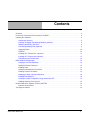
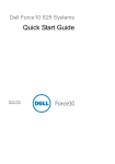
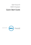
The S25P is shipped with universal front-mounting brackets (rack ears) attached. The screws for attaching
those ears to a standard 19-inch rack are in the bag that also contains the S-Series CD-ROM.
Position the S25P chassis in the rack. Secure the chassis with two screws through each bracket and onto the
rack post.
AC1
Stack
XFP2
ID
Alarm
5
XFP2
AC2
6
27
P28
S25-0
1-GE24P
Figure 1 Front-mounting the S25P
Note: The front-mounting installation above is one of several installation options contained in the
book Installing the S25P System. Other options include rear mounting, four-post mounting, and
table-mounting.
8
Installing the Hardware
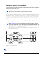
Connecting Stacking Ports (optional)
You can connect up to eight switches (S25P and S50V) together through their stack ports to configure them
to act as a unified system, called a stack.
Note: The original S50 model stacks only with other switches of that model.
The S25P contains two expansion slots in the rear, in either of which you can insert stacking modules. The
S25P system includes two optional types of stacking module — a single-port 24G module and a two-port
12G module. You can put either type of module in either of the two slots in the rear of the S25P, but you
cannot interconnect the two types, and Force10 does not support the use of all four ports of two 24G
modules.
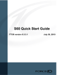
Use the optional stacking cables to connect the switches through the stack ports. One possible
configuration is depicted below.
Note: Figure on page 9 shows a connection between the top and bottom switches, from Stack
Port A on unit 1 to Stack Port B on unit 3. That connection completes a topology called a ring. That
ring is not necessary, because the ports are bi-directional, but a ring provides redundancy in case
of a failure of a stacking cable or port. If you use the single-port 24G modules, you can insert one
in each expansion slot to accomplish the ring topology.
Note: These instructions use “Stack Port A” and “Stack Port B” for clarifying the connections, but
the modules are not labeled.
fn00152s25P
Stack Port A
Stack Port B
Figure 2 Connecting Stack Ports
Note: The connectors in Figure 2 are depicted with captive screws. Instead, the connectors used on S25P
stack ports have latches, the same connectors as used for CX4 connections.
S25P Quick Reference
9
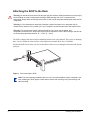
Supplying Power
Supply power to each S25P in a stack only after each switch is mounted and the stack ports are connected.
There is no on/off switch, and the stack members partly determine the stack management unit from the
order in which they come online (see above).
The S25P switch (catalog # S25-01-GE-24P) has two AC receptacles in the rear of the chassis (see
Figure 2 on page 9). The system can use either power source independently or in combination, in active/
backup mode. Connect the supplied AC power cord first to either receptacle of the S25P (on the right as
you face the rear of the chassis) and then to the power source (see AC Power Requirements on page 32).
Ensure that the cord is secure. If you connect both AC power supplies, ideally you would connect them to
separate circuits.
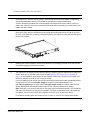
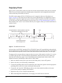
S25P-DC
(
,
,
10-Gigabit Modules or Stacking Modules (optional).
Optical ports numbered from left to right.
,
)
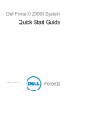
DC2
Ground Connector
-48V
-48V FG
RTN
fn00158s25P-DC
-48V
-48V FG
RTN
Ethernet Port Numbers
25 to 28, Right to Left
,
DC1
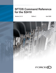
Figure 3 The S25P-DC Rear View
As shown above, the S25P-DC (catalog # S25-01-GE-24P-DC) has two DC terminal blocks on the right side.
You can supply power to either one or both, in active/backup mode (no precedence for either). The terminal
block on the left corresponds to the DC2 status LED on the front left of the switch; DC1 is on the right.
You must provide your own cables to connect to the power source. Cables must be sized for 11.5 A service
at -48VDC input (per NEC in the United States. Internationally, follow local safety codes.) Before you
make the cable connections, apply a coat of antioxidant paste to unplated metal contact surfaces. File
unplated connectors, braided straps, and bus bars to a shiny finish.
1. Make sure that the remote power source (the circuit breaker panel) is in the OFF position.
2. Remove the safety cover from the DC terminal block.
3. Connect the grounding cable to the FG terminal first, then connect the opposite end to the appropriate
grounding point at your site to ensure an adequate chassis ground.
4. Connect the -48 V and -48 V RTN (Return) cables to the switch terminals and then to the remote
power sources, ideally on separate circuit breakers.
5. Replace the safety covers on the DC terminal blocks.
6. When connecting both terminal blocks, do not supply power until both are connected.
10
Installing the Hardware
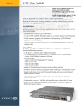
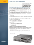
Installing SFP Transceivers (optional)
To install 1Gbps SFPs (Small
Form-factor Pluggable optical
transceivers) into the four
SFP ports at the right front of
the S25P:
1. Position the SFP so that
the bail is closed and on
top of the SFP.
2. Insert the SFP into the
port until it gently snaps
into place.
S25
-01-
GE
-24P
Note: When populated, the
four SFP ports shown in the
graphic automatically
preempt the four copper ports
labeled 21 through 24.
In other words, while you use
a particular optical port, you
cannot use the equivalent
copper port.
Note: For details on SFP and XFP optics supported by Force10, see
http://www.force10networks.com/products/specifications.asp
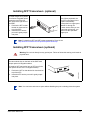
Installing XFP Transceivers (optional)
Warning: Do not look directly into any optical port. Failure to follow this warning could result in
physical harm.
The two module slots on the back of the S25P both
accept optional 10-Gigabit modules.
To install an XFP transceiver into an XFP port (in the
fiber optical version of the 10-Gigabit module):
1.
2. Insert the XFP into the port until it gently snaps
into place.
fn00160s50V
Position the XFP so that the bail is closed and on
top of the XFP.
Note: You can insert and remove optics without disabling the port or shutting down the system.
S25P Quick Reference
11
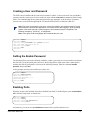
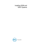
Connecting to the Console Port
Caution: Install a straight-through RJ-45 copper cable (a standard Ethernet cable) into the console
port. This is different from many other implementations that require a crossover cable (or rollover
cable). If connecting to a terminal server and using an Ethernet crossover cable, daisychain another
crossover cable to effectively get a straight-through cable connection. Many console terminal servers
use octopus cables that are crossover cables. As above, connect an additional crossover cable.
Sta
ck
ID
AC
1
XF
P2
5
XF
P2
6
Set your initial console terminal
settings to:
Ala
rm
AC
2
27
Console port pinout:
P2
8
Pin 1 = NC
Pin 2 = NC
Pin 3 = RXD
Pin 4 = GND
Pin 5 = GND
Pin 6 = TXD
Pin 7 = NC
Pin 8 = NC
fn00159s25P
Connect the RJ-45/DB-9
adapter that is shipped
with the S25P system to
the RJ-45 cable.
• 9600 baud rate
• no parity
• 8 data bits
• 1 stop bit
• no flow control
After establishing a connection, you
can modify the settings to match at
each end of the connection.
See the Getting Started chapter of the SFTOS Configuration Guide for other console port details, such as
setting the console timeout and the baud rate.
Basic Software Configuration
This S25P Quick Reference contains a small subset of the information that is provided in the Getting
Started chapter of the SFTOS Configuration Guide. That guide is available PDF format on the S-Series
CD-ROM and on the Documents tab of the iSupport website.
This section discusses the following configuration topics for the S25P:
• Creating a User and Password on page 13
• Setting the Enable Password on page 13
• Enabling Ports on page 13
• Setting the Management IP Address on page 14
• Enabling Telnet to the Switch on page 14
• Managing a Stack of S-Series Switches on page 14
• Installing New Software on page 15
• Creating a Simple Configuration using VLANs and STP on page 15
12
Basic Software Configuration
Creating a User and Password
The S25P comes installed with one read/write user named “admin”, with no password. You can add that
password, and also create up to five more read/write users with the username command in Global Config
mode. The command edits the user name and password in one statement, as shown below. Usernames
provide access to the S25P through both the CLI and the SFTOS Web User Interface (Web UI).
Note: Text boxes surrounded by oval lines, such as the following, are used throughout Force10
documentation to simulate the appearance of a terminal screen after logging in to the operating
system of the switch through a console program. The hostname prompt, exemplified in the
following example by “(Force10)”, is configurable.
Note: In this guide, bold text highlights the commands that you enter.
:
(Force10) >enable
(Force10) #config
(Force10) (Config)#username admin passwd apassword
User login name and password are set.
(Force10) (Config)#exit
(Force10) #exit
(Force10) >
Setting the Enable Password
The Privileged Exec password (commonly called the “enable” password), is not set when the switch starts
the first time. To set the enable password, access the Privileged Exec mode (also called “enable mode”)
and then the Global Config mode, as shown in the following example. Enter the command enable
passwd, then press Enter.
At the prompts, enter the password that you want to use:
:
(Force10) >enable
(Force10) #enable passwd
Enter new password:*******
Confirm new password:*******
Password Changed!
(Force10) #exit
Enabling Ports
When the switch is first installed, all ports are disabled by default. To enable all ports, enter no shutdown
all in Global Config mode, as shown here:
(Force10)
(Force10)
(Force10)
(Force10)
>enable
#config
(Config)#no shutdown all
(Config)#exit
Alternatively, you can use the no shutdown command at the specific interface level.
S25P Quick Reference
13
Setting the Management IP Address
Use the following the procedure to set up a management IP interface to the switch. You will need this to
access the switch through Telnet, SSH, TFTP, or the SFTOS Web User Interface.
Step
Command Syntax
Command Mode
Purpose
1.
show interface
managementethernet
User Exec or
Privileged Exec
Display current management IP
configuration.
2.
interface managementethernet
Global Config
Invoke the (Config-if-ma)# prompt.
3.
ip address ipaddr subnetmask
(Config-if-ma)# prompt
Set the IP address and subnet mask of
the management interface.
4.
management route default
gateway
Global Config
Set the IP gateway of the
management interface.
Note: The management address is reachable from VLAN 1. All physical ports are, by default, members of
VLAN 1, so the management address will be reachable from all enabled physical ports by default.
Enabling Telnet to the Switch
Access to the switch through a Telnet server is disabled by default. If you want to access the switch
through an SSH client, you would leave Telnet disabled and set up the SSH connection. See “Enabling
Secure Management with Secure Shell or Secure Sockets Layer” in the SFTOS Configuration Guide.
To enable Telnet access, first assign the management IP address (see Setting the Management IP Address
on page 14), then execute the ip telnet server enable command in Global Config mode.
Managing a Stack of S-Series Switches
When you connect a set of previously unconfigured S-Series switches, and you follow the instructions in
Connecting Stacking Ports (optional) on page 9, a startup algorithm automatically designates a unit to be
the management unit. You do not need to configure anything else specific to stack management.
If, on the other hand, you are modifying a stack, you will need to follow the directions that are in the
Stacking chapter of the SFTOS Configuration Guide.
If you need to upgrade the software in the stack, see the following section.
14
Basic Software Configuration
Installing New Software
As a convenience to purchasers of the SFTOS Layer 3 Package, the S25P comes with that software already
installed. So, other than checking the iSupport website for upgrades, you do not need to download new
code. The Layer 3 software package includes the Layer 2 package, so if you purchased just the Layer 2
package, your software license proscribes using the Layer 3 functionality. That is easy to do; simply do not
execute the routing command (Global Config mode); the Layer 3 functionality will be unavailable.
If you need to upgrade the SFTOS software, and you want to download the software from a TFTP server,
use the following command syntax:
copy tftp://tftp_server_ip_address/path/filename {image1 | image2}
For example: copy tftp://1.1.1.10/tftp/SFTOSdownload/SFTOS-S50-2.5.1.11.bin image2
In this example:
•
•
•
•
1.1.1.10 is the IP address of your TFTP server.
tftp/SFTOSdownload/ is the path to the software.
SFTOS-S50-2.5.1.6.bin is the software label.
image2 is the name of the storage location on your switch.
The choice of image1 or image2 is based on the fact that SFTOS 2.5.1 introduces support for two
software image locations on the switch. The software shipped on the switch is stored in the image1
location, so if you download new software to the image1 location, the next reload will boot up with that
software. If you save the new software to the image2 location, as shown above, and you want to install that
new software on the next reload, execute the command boot system image2 before executing reload.
You can use variations of the copy command to download or upload files to and from the switch. For
details on the command syntax, see the copy command in the SFTOS Command Reference. For more on
managing software and configuration files, see “Managing Configuration and Software” in the Getting
Started chapter of the SFTOS Configuration Guide. Also see “Upgrading Software in a Stack” in the
Stacking chapter.
Creating a Simple Configuration using VLANs and STP
Note: As noted in Enabling Ports on page 13, all ports are disabled by default. Enable them with
no shutdown all (Global Config mode), or individually with the no shutdown command on
each port (Interface Config mode).
:The following is an example of using the command line interface (CLI) to create VLAN 55, adding both a
tagged interface and an untagged interface to it (ports 5 and 6, respectively, in stack member unit 1): :
(Force10)
(Force10)
(Force10)
(Force10)
(Force10)
(Config)#interface vlan 55
(Conf-if-vl-55)#tagged 1/0/5
(Conf-if-vl-55)#untagged 1/0/6
(Conf-if-vl-55)#exit
(Config)#no shutdown all
S25P Quick Reference
15
For more on using the CLI to create VLANs, see the VLANs chapters in the SFTOS Command Reference
and SFTOS Configuration Guide.
Enabling Spanning Tree Protocol
Spanning Tree Protocol (STP) is off by default. First, you must enable STP globally. Next, enable STP on
the desired ports. Using the CLI to enable STP, it is possible to enable spanning tree globally and on all the
ports with just two commands — spanning-tree and spanning-tree port mode all. The following
example also shows the use of the show spanning-tree summary command to verify the configuration:
(Force10)
(Force10)
(Force10)
(Force10)
(Force10)
#configure
(Config)#spanning-tree
(Config)#spanning-tree port mode enable all
(Config)#exit
#show spanning-tree summary
Spanning Tree Adminmode...........
Spanning Tree Version.............
Configuration Name................
Configuration Revision Level......
Configuration Digest Key..........
0xac36177f50283cd4b83821d8ab26de62
Configuration Format Selector.....
No MST instances to display.
Enabled
IEEE 802.1s
00-01-E8-D5-A0-F7
0
0
Verify the convergence with the show spanning-tree interface interface command:
(Force10) #show spanning-tree interface 1/0/1
Hello Time.....................................
Port Mode......................................
Port Up Time Since Counters Last Cleared.......
STP BPDUs Transmitted..........................
STP BPDUs Received.............................
RSTP BPDUs Transmitted.........................
RSTP BPDUs Received............................
MSTP BPDUs Transmitted.........................
MSTP BPDUs Received............................
0
Enabled
0 day 0 hr 19 min 38 sec
2
593
0
0
4
0
(Force10) #write memory
![Your final step is to execute the write memory command to save the configuration.]!
Notable Differences between FTOS and SFTOS
This section describes the major differences in how SFTOS command usage on the S-Series differs from
FTOS on the E-Series. Users familiar with FTOS will notice enough similarities in the SFTOS CLI
environment on the S-Series that they can quickly learn the variations in syntax and usage.
Of course, there are more commands with more detailed options in FTOS than in SFTOS, because FTOS
runs the E-Series switches, which are more complex than the S-Series line supported by SFTOS.
16
Notable Differences between FTOS and SFTOS
Interface Nomenclature
The major difference between SFTOS and FTOS is that commands that contain a parameter in the form
slot/port in FTOS use a unit/slot/port parameter in SFTOS for both physical and logical interfaces.
For physical identifiers, the unit is the stack member number in an S-Series stack. For example, both FTOS
and SFTOS have the show interface command, but the SFTOS equivalent of show interface
gigabitethernet 2/11 (slot 2, port 11 in FTOS) would be show interface 1/0/11, where 1/0/11
represents unit 1 in the stack, slot 0, port 11. If the port were in unit 2 of the S-Series stack, the command
would be show interface 2/0/11.
Logical interface identifiers are automatically generated by SFTOS. They also use the unit/slot/port
convention, but system unit numbers are always 0, slot numbers are sequential, starting at 1, and the
interface numbers (in the third position) are also sequential, starting at 1 per slot.
Note: Starting with SFTOS 2.5.1, the integer IDs of LAGs (port channels) and VLANs that you assign to
the interfaces when you configure them are the IDs used throughout the configuration; the system no
longer assigns a logical ID in the unit/slot/port form.
Other CLI variations include:
•
•
•
Creating a static route: The SFTOS command ip route supports only IP addresses for setting the
next-hop router, while ip route in the FTOS also supports physical interfaces.
Setting the size of the logging buffer: The FTOS command logging buffered has a parameter
that enables you to set the size of the buffer, while SFTOS does not. Both FTOS and SFTOS invoke
debug logging with the number 7 for the severity level parameter. The SFTOS command is logging
buffered 7.
Displaying the MAC address table: Both FTOS and SFTOS have the show mac-address-table
command, but the SFTOS command show mac-addr-table provides more similar results to that
FTOS command. The SFTOS syntax contains the unit/slot/port form cited above, for example,
show mac-addr-table interface 1/0/4.
•
Displaying system information: The FTOS command show linecard is similar to show
version in SFTOS, which shows basic information, including the running software version and up
time. Other similar commands in SFTOS are show hardware and show sysinfo, and show
tech-support provides the results of a group of those similar commands.
•
service timestamps: This FTOS command is not available in SFTOS. SFTOS sets timestamps
automatically.
•
aaa authentication: This FTOS command is available in SFTOS as authentication.
S25P Quick Reference
17
The iSupport Website
Access to some sections of the iSupport website do not require a password to access. However, if some
section does require a password, you can request one at the iSupport website:
1. Click the Support link on the Force10 Networks home page: http://www.force10networks.com
2. Click the Account Request link.
3. Fill out the User Account Request form and click Send.
4. Click Login, and then enter the userid and password that you received by email.
The i-Support website (http://www.force10networks.com/support/) contains the following five tabs:
•
•
•
•
•
Home: Summary of open cases, RMA management, and field notices (as shown below)
Service Request: Case management
Software Center: Software downloads, bug fixes, and bug tracking tool
Documents: User documentation, FAQs, field notices, technical tips, and white papers
Support Programs: Information on the suite of Force10 support and professional support services.
For more on using the iSupport website and accessing services, see the Force10 Service and Support Guide,
available on the Home tab, as displayed above.
You can also contact the Force10 Technical Assistance Center (TAC) by email or phone. For details, click
the Contact Support link on the Force10 Support page: http://www.force10networks.com
18
The iSupport Website