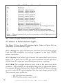
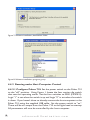
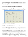
1
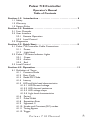
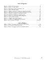
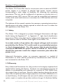
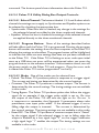
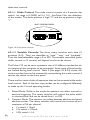
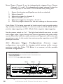
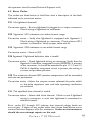
Pulsar 710 Controller
Operator’s Manual
& Installation Guide
Pulsar 710 Manual
1595.050017 REV- Manual, Operation, Pulsar 710
Packing list, Pulsar 710
The shipping container should contain the following items:
Pulsar 710 controller (1)
Installation CD (1)
Pulsar 710 operator’s manual (1)
3 Pin, Trigger input connectors (2)
2 Pin, Power input connector and cable (1)
USB cable (1)
Advanced illumination
24 Peavine Drive
Rochester VT 05767
802.767.3830
2
a d v a n c e d i l l u m i n a t i o n .c o m
Pulsar 710 Controller
Operator’s Manual
Table of Contents
Section: 1.0 Introduction . . . . . . . . . . . . . . . . . . . . . . . . . . . . . . . . . . 6
1.1 Safety
1.2 Warranty
1.3 Return Policy
Section: 2.0 Features . . . . . . . . . . . . . . . . . . . . . . . . . . . . . . . . . . . . . . . 7
2.1 Four Channels
2.2 User Interface
2.2.1 Remote Operation
2.2.2 Local Control
2.3 Diagnostics
Section: 3.0 Quick Start . . . . . . . . . . . . . . . . . . . . . . . . . . . . . . . . . . . . 8 3.1 Pulsar 710 Controller Cable Connections
3.1.1 Power
3.1.2 Light Head
3.2 Pulsar 710 Status Indicator Lights
3.2.1 Green
3.2.2 Amber
3.2.3 Red
3.3 Local Control
Section: 4.0 Operation . . . . . . . . . . . . . . . . . . . . . . . . . . . . . . . . . . . . . . . . . . 11
4.1 Definition of Terms
4.1.1 Constant Mode
4.1.2 Duty Cycle
4.1.3 Gated DC Mode
4.1.4 Latency
4.1.5 LED and light head characteristics
4.1.5.1 LED forward voltage
4.1.5.2 LED thermal resistance
4.1.5.3 LED voltage slope
4.1.5.4 Light head characteristics
4.1.6 Period
4.1.7 Pulse Width
4.1.8 Repetition Rate
4.1.9 Signatech II
4.1.10 Strobe and Constant (DC) modes
4.1.11 Timing Bypass
4.1.12 Trigger
Pulsar 710 Manual
3
4.1.13 Trigger Pass Through
4.1.14 Trigger Delay
4.2 Pulsar 710 Controller Cable Connections
4.2.1 Power
4.2.2 Trigger
4.2.3 RS 232/485
4.2.4 USB
4.2.5 Light Head
4.3 Pulsar 710 Status Indicator Lights
4.3.1 Green
4.3.2 Amber
4.3.3 Red
4.4 Host Computer Control (Remote)
4.4.1 Software Installation
4.4.2 Running Under Host Computer Control
4.4.2.1 Configure Pulsar 710
4.4.2.2 Launch Pulsar 710 Controller Utility
4.4.2.3 Pulsar 710 Utility Dialog Box Status Indicators
4.4.2.4 Pulsar 710 Utility Dialog Box Output Controls
4.5 Local Control
4.5.1 Controls
4.5.1.1 Mode Control
4.5.1.2 Variable Controls
4.6 External Trigger Interface
4.6.1 Alternate Trigger Configurations
4.7 Timing Bypass
Section: 5.0 Custom Programming . . . . . . . . . . . . . . . . . . . . . . . . 28
Section: 6.0 Troubleshooting . . . . . . . . . . . . . . . . . . . . . . . . . . . . . . . 28 6.1 Pulsar 710 Status Indicator Lights
6.2 Error Codes
Section: 7.0 Specifications . . . . . . . . . . . . . . . . . . . . . . . . . . . . . . . . . 30
Section: 8.0 Appendix . . . . . . . . . . . . . . . . . . . . . . . . . . . . . . . . . . . . . 33
A: NPN / PNP - PLC trigger connection
B: Activate differential trigger
C: Activate Trigger pass through
D: Installation Drawing
4
a d v a n c e d i l l u m i n a t i o n .c o m
List of Figures:
Figure 1: Pulsar 710 front panel . . . . . . . . . . . . . . . . . . . . . . . . . . . . . . . . . . . . . . . . . . . . . . 9
Figure 2: Pulsar 710 rear panel . . . . . . . . . . . . . . . . . . . . . . . . . . . . . . . . . . . . . . . . . . . . . . . 9
Figure 3: Attaching a light to the Pulsar 710 . . . . . . . . . . . . . . . . . . . . . . . . . . . . . . . . . . 9
Figure 4: Status indicator lights . . . . . . . . . . . . . . . . . . . . . . . . . . . . . . . . . . . . . . . . . . . . . . 10
Figure 5: Output connector connection diagram example . . . . . . . . . . . . . . . . . . .15
Figure 6: USB type B connector. Pulsar end (cable and jack) . . . . . . . . . . . . . . . . .17
Figure 7: Software installation, destination folder . . . . . . . . . . . . . . . . . . . . . . . . . . . . .18
Figure 8: Software installation, program group . . . . . . . . . . . . . . . . . . . . . . . . . . . . . . . 18
Figure 9: Pulsar 710 controller utility dialog box . . . . . . . . . . . . . . . . . . . . . . . . . . . . . 19
Figure 10: Front panel controls . . . . . . . . . . . . . . . . . . . . . . . . . . . . . . . . . . . . . . . . . . . . . . 22
Figure 11: Trigger connection diagram . . . . . . . . . . . . . . . . . . . . . . . . . . . . . . . . . . . . . . . 26
Figure 12: Pulsar 710 trigger wiring schematic . . . . . . . . . . . . . . . . . . . . . . . . . . . . . . . 34
Figure 13 & 14: Pulsar 710 PCB . . . . . . . . . . . . . . . . . . . . . . . . . . . . . . . . . . . . . . . . 35 & 37
List of Tables:
Table 1: Pulsar 710 output connector, pin description . . . . . . . . . . . . . . . . . . . . . . . 16
Table 2: Local control operating modes . . . . . . . . . . . . . . . . . . . . . . . . . . . . . . . . . . 23-24
Table 3: Pulsar 710 trigger connector, pin description . . . . . . . . . . . . . . . . . . . . . . . 25
Pulsar 710 Manual
5
Section: 1.0 Introduction
The Pulsar 710 Controller, used in conjunction with an external 24VDC
power supply, is a compact, 4 channel, high power current source
incorporating a wide range of flexibility for selecting the operating
parameters. The unit can be configured to operate as a strobe unit or a
constant current (DC) source. The unit may be controlled and operated
locally (with some restrictions) or remotely via a USB interface and host
computer.
The balance of this manual contains the necessary operating instructions,
specifications and other details required to allow the user to utilize the
full capabilities of the Pulsar 710.
1.1 Safety
The Pulsar 710 is designed to protect Advanced illumination (Ai) light
d
d
heads having the Signatech I or
Signatech II light
head identification
parameters. When using light heads configured for Signatech I, an adapter
cable must be used to connect these lights to the Pulsar 710.
In certain modes of operation, the output voltages and currents
provided by the Pulsar 710 could result in a potentially injurious
or fatal electrical shock. For this reason, light heads should be
connected BEFORE the power switch is turned on. At no time
should the operator touch the output connector pins when the
power is on.
Advanced illumination makes no warranty, expressed or implied, if
illumination or other devices produced by manufacturers other than Ai
are connected to the Pulsar 710.
1.2 Warranty
Every Advanced illumination, Inc. (Ai) product is thoroughly inspected and
tested before leaving the factory. Products are warranted to be free of
defects in workmanship and materials for a period of TWO YEARS from
the original date of purchase. Should a defect develop during this period,
return the complete product, freight prepaid, to one of Ai’s distributors or
to the Ai factory. Ai will inspect the unit, and if a defect is found will, at our
option, repair or replace the product without charge. Ai disclaims liability
6
a d v a n c e d i l l u m i n a t i o n .c o m
for any implied warranties, including implied warranties or “merchantability”
and “fitness for a specific purpose.”
Ai cannot be held responsible for the unauthorized or inappropriate use
of our products.
NO LIABILITY FOR CONSEQUENTIAL DAMAGES.
In no event shall Advanced illumination, Inc. be liable for consequential,
special, incidental or indirect damages of any kind arising from the sale or
use of products.
1.3: Return Policy
Standard Products may be returned within 30 days of receipt of the order.
Products must be in resalable condition, in function and appearance, with
shipping charges prepaid. A restocking fee of 15% will be applied to all
items accepted for return to stock. If you need to make a return, please
call our Customer Service Department at 802.767.3830 x237 or x222
for a Return Merchandise Authorization (RMA) number. Clearly mark
the outside of the package with the RMA number.
NO RETURNS CAN BE ACCEPTED FOR STANDARD VARIATION,
CUSTOM VARIATION AND CUSTOM PRODUCTS.
There are currently over 100,000 unique configurations of the Ai product
line. Therefore, we cannot restock a light built to your specifications. We
would be glad to help you order your light if you are unsure of the correct
part number or your exact requirements.
Section: 2.0 Features
The following is a brief overview of the features provided by the Pulsar
710. These features will be covered in greater detail within the Operation
and Specification sections of the manual.
2.1 Four Channels
Four output channels, capable of high output power are provided. Each
will provide up to 2A of constant current drive in the dc mode or up
to 25A of pulsed current drive in the strobe mode. The current of
each channel is independently selectable. Output pulse widths can be
Pulsar 710 Manual
7
set between 1 and 999 microseconds in 1 microsecond increments at
pulse repetition rates up to 200 Hz.
2.2 User Interface
2.2.1 Remote Operation: Remote operation via a host computer
allows the operator to make full use of the flexibility offered by the
Pulsar 710. Communication is accomplished by a USB interface.
Operating parameters are set by user friendly Windows based Pulsar
710 controller software. Supported operating systems are Windows
2000 and Windows XP.
2.2.2 Local Control: Front panel controls permit the operator
to select the operating parameters under local control. Selected
parameters are stored in electrically erasable programmable read-only
memory (EEPROM).
2.3 Diagnostics
A comprehensive set of diagnostic routines and indicators are provided.
Error codes are displayed by the Pulsar 710 via LED indicators on the
front panel. Code definitions are found in section 6.0 “Troubleshooting”
where diagnostics are covered in greater detail.
Section: 3.0 Quick Start
The purpose of this section is to allow the operator to perform a quick
functional test. This will permit an easy checkout of the Pulsar 710 and
attached light head for proper operation.
3.1 Pulsar 710 Controller Cable Connections:
Two physical cable connections will be required to operate the Pulsar
710 and light head in self test mode. Figure 1 shows the front panel of
the Pulsar 710.
3.1.1 Power: The Pulsar 710 requires an external 24 volt supply for
operation. A power cable is provided. Plug the 2 pin connector into the
socket labeled “VDC INPUT”. Observe the polarity markings on the
panel below the VDC INPUT socket. Refer to section 4.2.1 for more
details regarding the 24 volt supply.
8
a d v a n c e d i l l u m i n a t i o n .c o m
EXTERNAL TRIGGER
INTERFACE CONNECTOR
RS232/485 INTERFACE
(FUTURE IMPLEMENTAION)
EXTERNAL TRIGGER
100's 10's
1
2
3
8
7
1
4
0
5
9
2
3
8
7
1
4
0
6
5
9
1's
6
2
3
8
7
MODE
USB
RS232/485
4
0
4
5
6
1
2
3
VDC INPUT
POWER
STATUS
POWER
0
5
9
ERROR
1
6
+ -
MAIN POWER
SWITCH
USB INTERFACE
TO HOST COMPUTER
VARIABLE CONTROL
ROTARY SWITCHES
LED STATUS
INDICATOR
MODE CONTROL
DIP SWITCHES
EXTERNAL DC POWER
INPUT CONNECTOR
Figure 1: Pulsar 710 front panel
3.1.2 Light Head: Figure 2 shows the rear panel of the Pulsar 710 and,
in particular, the location of the 14 pin output connector.
Figure 2: Pulsar 710 rear panel
Figure 3 shows how the output
connector on the rear panel of
the Pulsar 710 mates with the
light head connector. Plug the
connector from the light head into
the 14 pin socket in the rear of the
Pulsar 710 as shown in Figure 3.
Figure 3: Attaching a light to the Pulsar 710
3.2 Pulsar 710 Status Indicator Lights:
The Pulsar 710 has three LED indicator lights as shown in Figure 4:
3.2.1 Green: This light indicates that the Pulsar 710 has power either
from the USB connection to the host computer or the main 24VDC
power connection.
3.2.2 Amber: The amber light indicates the operational status of the
Pulsar710. A blink rate of once per second indicates normal operation.
A blink rate of 5 times per second indicates an error condition.
Pulsar 710 Manual
9
PULSAR 710 STATUS INDICATOR LIGHTS
3.2.3 Red: The red light blinks an error
code in the case of an error condition.
The condition is indicated by three sets
of sequential flashes. For example: 4
flashes followed by 2 flashes followed by
3 flashes indicates an error code of 423
which signifies that the main power switch
is off. Two common error codes are:
POWER
ERROR
STATUS
POWER
0
1
Figure 4: Status indicator Lights
• 351: No light head detected.
• 423: The main power switch is off.
(Refer to section 6.0 “Troubleshooting” for more detailed error code
information.)
3.3 Local Control
For the purposes of this procedure, the Pulsar 710 will be operated in self
test mode utilizing local control.
Using Figure 1, locate the four section dip switch that sets the operating
mode of the Pulsar 710. Set the four switches to 1110, from left to
right. Logic “1” is set when the switch is up and logic “0” when the
switch is down. This is Mode 14 and enables an internal trigger having a
repetition rate of 10 Hz. The pulse width is set by the three 10 position
rotary switches at the far left of the front panel. The rotary switches set
the pulse width in microseconds, up to 999 microseconds. A reasonable
starting pulse width for testing is 20 microseconds. Example: Set the
“10’s” switch to “2”, leaving the “100’s” and “1’s” switches set to “0”.
Set the power switch to “on”. The selected mode is activated by the
Pulsar 710 when the power is applied or when the light head is changed.
Assuming that the connected light head is configured with one of Ai’s
two Signatech options, the Pulsar 710 will set a safe current level for
the light head based on the repetition rate and the pulse width. Older
light head’s without Signatech will cause the Pulsar 710 to shut down
and flash error code 352 (See chapter 6.0 “troubleshooting” for a
complete listing of trouble codes). The pulse width may now be varied
using the three rotary switches. Successful operation in this mode
indicates that the Pulsar 710 and light head are functioning correctly.
10
a d v a n c e d i l l u m i n a t i o n .c o m
Section: 4.0 Operation
The following section details the procedures for operation of the Pulsar
710 Controller and defines its various operating modes.
4.1 Definition of Terms
The following terms are used within this manual and, more generally, in
relation to machine vision illumination.
4.1.1 Constant Mode: The Pulsar 710 produces a constant output.The
current is determined by the control settings. The timing settings are not
available in this mode.
4.1.2 Duty Cycle: The ratio of the time the light head is “on” (pulse
width, Pw) to the time it is “off” (period, Tp). Calculated as (Pw / Tp) x
100. The result is expressed in percent. The Signatech II feature of the
Pulsar 710 allows the Pulsar 710 to limit the maximum duty cycle based
on the characteristics of the driven light head.
4.1.3 Gated DC Mode: The Pulsar 710 produces a constant output
that is “Gated” by the trigger signal. “Gating” refers to the ability of the
Pulsar 710’s output to be turned on and off in constant mode by any one
of the trigger inputs. If the selected trigger is set to falling edge the output
is enabled by a low signal on the trigger, otherwise a high signal enables
the output. The timing settings are not available in this mode.
4.1.4 Latency: The time between the receipt of a trigger signal and
initiation of the output drive pulse. The latency is the sum of the risetimes and propagation delays within the trigger processing circuitry. This
time is purposely kept to a minimum. Latency is not adjustable and should
not be confused with trigger delay described in section 4.1.14. See section
7.0 Specifications for latency specs.
4.1.5 LED and Lighthead Characteristics: Many factors contribute
to the operational parameters of an LED light head. To optimize Pulsar
710/light head operation, these characteristics are stored as part of the
information provided to the Pulsar 710 by the Signatech II circuit within
the light head. Some of the variables that affect how the light head can be
driven are outlined below.
Pulsar 710 Manual
11
4.1.5.1 LED Forward Voltage: The forward voltage drop across an
LED (Vf) depends upon the nature of the semiconductor junction and the
current through the LED. The specified Vf for an LED is usually given at its
recommended operating current. Please note that when driven by high
current pulses, Vf can increase by 10 to 20 times. For this reason voltage
levels at the Pulsar 710 output can be as high as 100 volts.
4.1.5.2 LED Thermal Resistance: A measure of the temperature
difference between the LED junction and the LED connection to an
external heat sink. Overheating of the junction is the primary cause of
failure in LEDs. The value of the LED thermal resistance, combined with
the heat sink thermal resistance and the overall thermal time constant
determine the maximum pulse width, pulse current, and duty cycle of the
light head.
4.1.5.3 LED Voltage Slope: The relationship between Vf and the
forward current If, used by Signatech II to calculate the voltage required
to provide the desired current.
4.1.5.4 Lighthead Characteristics: Also contained within the data
provided by Signatech II to the Pulsar 710 are the number and type of
LEDs in each string and the number of parallel strings connected to each
channel.
4.1.6 Period: The length of time between two successive pulses or the
reciprocal of the pulse frequency.
4.1.7 Pulse Width: The length of time the light head is activated by the
Pulsar 710. This is typically measured between the 50% amplitude points
of the pulse.
4.1.8 Repetition Rate: The rate at which successive pulses are initiated.
Also known as frequency, which is measured in Hertz (cycles per second). Repetition rate is usually multiple times per second.
4.1.9 Signatech II: A proprietary feature of Ai light heads and the Pulsar
710. Signatech identifies the type of light head connected to the Pulsar
710 and maintains safe operating limits for each type. The Pulsar 710 can
be set so that Signatech preferentially limits pulse current, pulse width,
or period to remain within the safe power dissipation range of the light
head.
12
a d v a n c e d i l l u m i n a t i o n .c o m
4.1.10 Strobe and Constant (dc) Modes: The strobe mode is used
to “freeze” a moving item at a particular moment in time. Typically, with
LED illumination sources, the strobe mode involves driving the light head
with a high current, short duration pulse. This provides a very intense light
output pulse. As long as the duty cycle is kept short, no damage to the
LEDs occur as a result of the high current. Where a non-moving object is
to be viewed, the constant mode is used. The light is simply turned on and
left on for as long as desired. In this mode the drive current is a fraction
of that used in the strobe mode. The Pulsar 710 limits this current to a
level where the light head can be operated indefinitely without damage.
4.1.11Timing Bypass: This is a strobing function with high output power
that allows the Pulsar 710 to track the pulse width of the input trigger
pulse. This function is not to be confused with gated DC mode. It is always
important to remember that Signatech II takes precedence to protect the
connected light head. Therefore, during timing bypass the output pulse
width will only track the trigger signal until the maximum allowed pulse
width for the selected current is reached. After this point, increasing the
trigger pulse width will have no effect on light head output.
4.1.12 Trigger: The signal which initiates an output from the Pulsar 710
to the light head. The trigger signal is normally generated by an external
source such as a camera or other sensor. Several modes of trigger
operation are provided for in the Pulsar 710. The trigger may start on
either a rising or falling edge. For test purposes, the Pulsar 710 also has
an internal trigger source.
4.1.13 Trigger Pass Through: Also known as “loop through,” this
feature allows several controllers to be driven simultaneously by the
same trigger source. To minimize latency of the trigger pass through, the
trigger input and output are not buffered. This looped through signal is
then daisy chained to a second controller or device. The purpose is to
minimize any delay between the time the first controller in the chain and
succeeding controllers receive the trigger signal. To enable this feature
refer to Appendix “C”.
4.1.14 Trigger Delay: Certain applications require that a known, fixed
time elapse between the receipt of a trigger signal and the initiation of
an output pulse. This is the trigger delay. For example, if the trigger signal
Pulsar 710 Manual
13
is received from a position sensor, prior to the arrival of the item to be
inspected, a delay to account for that transit time would be introduced.
If the trigger signal originates from the camera at the start of the shutter
opening, a short delay might be introduced to assure the shutter is fully
open or that the illumination pulse occurs elsewhere within the frame
time.
4.2 Pulsar 710 Controller Cable Connections
Four physical connections will be required to operate the Pulsar 710 and
light head. Refer to figure 1 for an illustration of the Pulsar 710’s front
panel.
4.2.1 Power: The input power connector is located near the lower right
hand corner of the Pulsar 710’s front panel. The Pulsar 710 requires an
external 24 volt supply for operation. The power supply needs to have
sufficient amperage rating to drive the light head in the desired mode
of operation. Ai recommends a minimum of 8A for constant current
operation and 5A for pulsed operation. A power cable is provided. Plug
the 2 pin connector into the socket labeled “VDC INPUT”. Observe the
polarity markings on the panel below the VDC INPUT socket.
4.2.2 Trigger: The trigger input connector is located near the center of
the Pulsar 710’s front panel. The single ended trigger levels are CMOS/
TTL compatible but will accept input pulses as great as 30 V. Two input
trigger connectors are provided. Each one can accommodate two trigger
inputs, thus allowing up to four single ended triggers. One differential input
trigger can also be configured. For more detailed triggering information
refer to section 4.6 “External Trigger Interface”.
4.2.3 RS232/485 Connections: The RS232/485 connector is located
just to the left of the trigger connector. Upon future implementation, the
Pulsar 710 will accept a RS232/485 computer connection.
4.2.4 USB: The USB connector is located just to the left of the RS232/485
connector. A host computer will communicate with the Pulsar 710 via
this USB connection. Connect the provided USB cable between the USB
connection on the host computer and the socket labeled USB on the
Pulsar 710. The Pulsar 710 is Microsoft HID USB compliant. Therefore, a
host computer with Windows 2000 or Windows XP will auto-detect the
Pulsar 710.
14
a d v a n c e d i l l u m i n a t i o n .c o m
A
Signatech II DS2431
Cut pin 3 of DS2431
8-Feb-2006
Rev: 1.0
A
CON14
B
C
D
J23
1
2
3
4
5
6
7
8
9
10
11
12
13
14
1
3
2
1
2
Note: Signatech II Chip and Loopback from
pin 11 to 13 must be present for light to
function.
3
SP069-WHIC3-001
Advanced Illumination
4
B
C
D
4
3
2
1
Figure 5: Output connector connection diagram example
4.2.5 Light Head: Power output is supplied through the 14 pin terminal
block / connector on the back panel of the Pulsar 710. Table 1 identifies
the function of each pin within the 14 Pin connector. Figure 5 is an example
of a connection diagram for the output connector that is factory wired
before the light head(s) leave Advanced illumination. Plug the connector
from the light head into the 14 pin socket as shown in Figure 3.
Pulsar 710 Manual
15
Pulsar 710 Output Connector Pinout:
Pin
1
2
3
4
5
6
7
8
9
10
11
12
13
14
Function
Channel 1 supply: Positive
Channel 1 return: Negative
Channel 2 supply: Positive
Channel 2 return: Negative
Channel 3 supply: Positive
Channel 3 return: Negative
Channel 4 supply: Positive
Channel 4 return: Negative
Signatech 1: Identification Resistor 1
Signatech 1: Identification Resistor 2
Light head detection: Connects to Pin 13 Digital Ground
Signatech II: EPROM data read/write
Digital Ground: Grounds EPROM, Light head detect
Power Ground: Chassis Ground, Connect cable shielding
Note: Channel returns shall not be connected to either Digital ground or
Power Ground
Table 1: Pulsar 710 output connector, pin description
4.3 Pulsar 710 Status Indicator Lights:
The Pulsar 710 has three LED indicator lights. Refer to Figure 4 for an
illustration of these indicator lights.
4.3.1 Green: This light indicates that the Pulsar 710 has power either
from the USB connection to the host computer or the main 24VDC
power connection.
4.3.2 Amber: The amber light indicates the operational status of the
Pulsar 710. A blink rate of once per second indicates normal operation.
A blink rate of 5 times per second indicates an error condition.
4.3.3 Red: The red light blinks an error code in the case of an error
condition. The condition is indicated by three sets of sequential flashes.
For example: 4 flashes followed by 2 flashes followed by 3 flashes indicates
an error code of 423 which signifies that the main power switch is off. Two common error codes are:
• 351: No light head detected.
• 423: The main power switch is off.
16
a d v a n c e d i l l u m i n a t i o n .c o m
(Refer to section 6.0 “Troubleshooting” for more detailed error code
information.)
4.4 Host Computer Control (REMOTE)
If it is intended to operate the Pulsar 710 under
Local Control skip to section 4.5 “Local Control”.
To take full advantage of the flexibility of the
Pulsar 710, software is provided which permits
the operating parameters to be set by a host
computer. The host computer will be connected
to the Pulsar 710 via a USB port utilizing a USB
Type B connector. (See Figure 6.) The USB port
is Microsoft HID compliant.
Figure 6: USB type B connector
4.4.1 Software Installation: The Pulsar 710 Controller utility program
is required to set the operational parameters of the Pulsar 710. This
utility program is included on the supplied CD and is installed as follows:
Note: Administrator Access to the system is usually required to install
the software.
Note: Supported operating systems are Windows 2000 and Windows
XP.
1. Insert Installation CD. If “Autoplay” is disabled, double click on “My
Computer” and open the CD drive (Usually “D or E”)
2. Select Pulsar 710 installation from menu on CD.
3. Close all open applications when prompted and press OK.
4. If necessary change the installation folder (using the default is
recommended) and click the large button to begin the installation. (See
figure 7.)
5. Select a Program Group or use the default (Advanced Illumination) and
click Continue. (See figure 8.)
Note: If for some reason the automatic installation program can not be
used, the software can be manually installed as follows: Place the four
support files from the CD, (Pulsar_V00_02_C.exe, MPDH8USB.DLL,
PulsarAPI.dll, and ecodes.ini) in the same folder on the PC. Execute
the file called “Pulsar_V00_02_C” to setup the operation parameters
of the controller.
Pulsar 710 Manual
17
Figure 7: Software installation, destination folder
Figure 8: Software installation, program group
4.4.2 Running under Host Computer Control
4.4.2.1 Configure Pulsar 710: Set the power switch on the Pulsar 710
to the “off” position. Using Figure 1, locate the four section dip switch
that sets the operating mode. Set the four switches to 0000 (MODE 0).
Logic “1” is set when the switch is up and Logic “0” is set when the switch
is down. If you haven’t done so already, connect the host computer to the
Pulsar 710, using the supplied USB cable. Set the power switch to “on”.
There will be no output from the Pulsar 710 to the light head on startup.
All parameters will now be controlled by the host computer.
18
a d v a n c e d i l l u m i n a t i o n .c o m
4.4.2.2 Launch Pulsar 710 Controller Utility: To run the program;
go to Start -> Programs -> Advanced Illumination -> Pulsar Controller.
Upon execution of the Pulsar Controller Utility program, the dialog box
shown in figure 9 will appear.
4.4.2.3 Pulsar 710 Utility Dialog Box Status Indicators:
4.4.2.3.1 Main Power: A green light and “ON” indicate the main power
switch on the Pulsar 710 is turned on. Otherwise there will be a red light
and “Off”. Settings can be transferred from the host computer to the
Figure 9: Pulsar 710 controller utility dialog box
Pulsar 710 with the main power switch off. The main power switch must
be “ON” in order to drive the light head.
4.4.2.3.2 Light head: A green light and “Ok” indicate that there is a
light head connected to the Pulsar 710. The type of light head will also be
displayed when available.
4.4.2.3.3 USB Connection: A green light and “Ok” indicate that a
USB connection has been established between the host computer and the
Pulsar 710. A USB connection is required to set up the Pulsar 710.
4.4.2.3.4 Status Panels: The two panels below the indicators show
connection status details. The top panel shows the results of the last
Pulsar 710 Manual
19
command. The bottom panel shows information about the Pulsar 710.
4.4.2.4 Pulsar 710 Utility Dialog Box Output Controls:
4.4.2.4.1 Select Channel: The buttons labeled 1, 2, 3, and 4 select which
channel the settings are to apply to. Synchronize and Equalize options can
be selected by checking the appropriate box.
• Synchronize: When this box is checked, any change in the settings for
the selected channel are added to the three unselected channels.
• Equalize: When this box is checked the settings of the selected channel
are applied directly to the three unselected channels.
4.4.2.4.2 Program Button: None of the settings described below
will take effect until the Pulsar 710 is programmed. Pressing the program
button will transfer the settings from the host computer to the Pulsar 710
allowing the settings to take effect. The program button will be highlighted
to indicate that there are new settings that have not yet been transferred
to the Pulsar 710. If the Pulsar 710 is flashing an error code upon initial
start up a USB time out error will be experienced when you press the
program button on the software interface. If this situation occurs, turn off
the power switch on the Pulsar 710 and program. Once the error code
is cleared the Pulsar 710 can be programmed “on the fly.”
4.4.2.4.3 Mode: One of five modes can be selected here.
• Pulsed: The Pulsar 710 produces pulses in response to a trigger signal.
The current and timing are determined by the control settings.
• Constant: The Pulsar 710 produces a constant output. The current is
determined by the control settings. The timing settings are not available
in this mode.
• Timing Bypass: The Pulsar 710 produces pulses that follow the trigger
signal. As an example, if the trigger pulse width is set to 10u secs
the output of the Pulsar 710 will turn the light on for 10u sec. It
is important to remember that Signatech II parameters always take
precedence over input pulse width. If the selected trigger is set to
falling edge the output is inverted. The current is determined by
the control settings: The timing settings are not available in this mode.
• Gated DC: The Pulsar 710 produces a constant output that is “Gated”
by the trigger signal. If the selected trigger is set to falling edge the
output is enabled by a low signal, logic “0” on the trigger, otherwise
a high signal, logic “1” enables the output. The timing settings are not
available in this mode.
20
a d v a n c e d i l l u m i n a t i o n .c o m
• Test: The Pulsar 710 outputs pulses at 10 hertz. The current and timing
are determined by the control settings.
4.4.2.4.4 Control Settings: There are three parameters that can be
set to control the output of the Pulsar 710.
• Current: The current setting determines the brightness of the light
output.
• Pulse Width: This is the length of the output pulse in microseconds.
• Delay: This is the time in microseconds, between detection of a trigger
signal and the start of the output pulse. Each parameter can be set by
adjusting its slider control or by entering the value directly in the text
box. Each slider control has a scale adjustment.
All settings are internally checked by the Pulsar 710 for compatibility with
the attached light head. Settings that will overdrive the light head will not
be allowed. If an unsafe setting is attempted, either the current or the
pulse width will automatically be reduced to a safe level and a message will
be displayed in the status box.The protection setting determines whether
pulse width or current is adjusted.
4.4.2.4.5 Protection: This selection determines what setting, timing or
current, is adjusted to produce a safe setting for the light head.
• Adjust Timing: Pulse width is reduced and current setting will be
maintained, so that the light head is not over driven.
• Adjust Current: Current is reduced and pulse width setting will be
maintained, so that the light head is not over driven.
Note: In some cases current may be adjusted when Adjust Timing is
selected. This happens when the current setting exceeds the absolute
maximum current setting for the light head. In this case current would
be reduced to the absolute maximum current and then timing adjusted
as necessary.
4.4.2.4.6 Triggers: This selection determines which trigger input drives
the selected channel in Pulse, Gated DC and Timing Bypass modes. Use
the edge selection to choose the rising or falling edge.
4.5 Local Control
4.5.1 Controls: There are two primary front panel controls on the
Pulsar 710. These are the mode and variable controls. Figure 10 shows
Pulsar 710 Manual
21
these two controls.
4.5.1.1 Mode Control: The mode control consists of a 4 position dip
switch. Its range is 0 (0000) to15 (1111). See Table 2 for the definition
of the modes. The down position is logic “0”, and the up position is logic
“1”.
PULSAR 710 FRONT PANEL CONTROLS
100's
1
2
3
10's
1
4
0
5
9
8
7
6
2
3
1's
1
4
0
5
9
8
7
6
MODE
2
3
8
7
4
0
5
9
6
1
2
3
4
Figure 10: Front panel controls
4.5.1.2 Variable Controls: The three rotary switches each have 10
positions (0-9). They are identified as “ones,” “tens,” and “hundreds.” Thus, the total selectable range is 0 to 999. The variable controlled (pulse
width, current, or % current) will depend on the mode chosen.
The Pulsar 710 can be set to operate in one of 15 different modes that do
not require a host computer to be connected. Some levels of functionality
are limited during local control. Table 2 (See pages 23 & 24) shows the
various modes that can be accessed by manipulating the mode control 4
section dip switch on the front panel.
There are four main modes of operation that can be accessed while under
local control. Each of the four main modes can be configured differently
to make up the 15 total operating modes.
1. Pulsed Mode: While in this mode the operator can select internal or
external triggering. The rotary switches will control the pulse width,
in microseconds, and can be varied from 1 to 999.
2. Constant Mode: The operator can select between absolute and gated
absolute modes. The rotary switches will control the current up to a
maximum of 2A per channel.
a. 1’s switch = 10mA
b. 10’s switch = 100mA
c. 100’s switch = 1A
22
a d v a n c e d i l l u m i n a t i o n .c o m
Table
P u l2:sLocal
a r control
7 1 0 operating
M a n umodes
al
23
0110
0111
1000
1001
1010
1011
Constant Mode with percent of maximum
current adjustment.
Constant Mode with percent of maximum
current adjustment, trigger acts as on/off.
Leading rising edge triggered, width
controlled by trigger falling edge or maximum
allowed pulse width, whichever comes first.
Leading falling edge triggered, width
controlled by trigger rising edge or maximum
allowed pulse width, whichever comes first.
Constant Percentage
Gated DC Percentage
Timing Bypass Rising
Timing Bypass Falling
Reserved
Reserved
Reserved
PC Only
Internal Trigger 10Hz
6
7
8
9
10
11
12
13
14
15
Factory Reset
1101
1110
1111
No output on startup. Operational parameters
configured via PC interface.
Internal 10Hz trigger for testing.
All configuration data in internal storage is
reset to factory defaults.
1100
0101
Constant Mode with direct current
adjustment, trigger acts as on/off.
5
Gated DC Absolute
Constant Absolute
4
0100
None
None
Set by PC
1
1
1
None
1
None
Channel Current, 0.01A /bit, 2A MAX
1 bit per percent of MAX light head
current. 100% MAX setting.
None
None
Set by PC
Falling
Rising
None
Pulse Width, 1 µsec / bit
None
Channel Current, 0.01A / bit, 2A MAX
Channel Current, 0.01A / bit, 2A MAX
1 bit per percent of MAX light head
High for On current. 100% MAX setting.
None
High for On Channel Current, 0.01A /bit, 2A MAX
None
1
0011
Constant Mode with direct current
adjustment.
Pulse mode with falling edge trigger.
Pulse Falling
3
Pulse width, 1 µsec / bit
Pulse width, 1 µsec / bit
Rising
Falling
1
As per stored operating mode
configuration.
None
Rotary Switch Function
0010
Pulse mode with rising edge trigger.
Pulse Rising
2
EE
Trigger
Sensing
EE
0001
All configuration data sourced from internal
storage, rotary switches operational.
EE with Rotary
1
EE
Trigger
Input
Number
EE
0000
DIP Switch
Settings
(1234)
All configuration data sourced from internal
storage, rotary switches not operational.
Description
EE without Rotary
Mode Name
0
Operational
Mode
Notes:
Operational Mode is determined on startup or when a new lighthead is attached, rotary
switches are active during operation
Switch Settings: 0 - Down or Closed, 1 - Up or Open
EE - Internal Electrically Erasable Programmable Read Only Memory (EEPROM) used to store
Pulsar configuration information
PC - Remote computer attached to Pulsar via USB interface
Reserved locations available for future operation modes
Only one of the four possible trigger inputs can be selected.
Table 2 (continued)
3. Percentage Mode: The operator can select between constant and
gated DC modes. The rotary switches will control the current as a
percentage of the maximum current that Signatech II calculates for
the light head. 100% is the maximum setting.
a. 1’s switch = 1%
b. 10’s switch = 10%
c. 100’s switch = 100%
4. Timing Bypass Mode: This is another variation of the pulse mode,
where the operator can select between rising and falling edge trigger
signals. The rotary switches will control the current up to a maximum
of 9.99A per channel.
a. 1’s switch = 10mA
b. 10’s switch = 100mA
c. 100’s switch = 1A
Note: Signatech I and II will protect light heads from being over driven.
Therefore when maximum values of pulse width and/or current are
reached, rotation of the switches beyond these values does not result
in increased output.
4.6 External Trigger Interface
The Pulsar 710 can accept up to 4 single ended TTL/CMOS input triggers,
or 1 differential RS232/485 logic level input trigger. The differential trigger
would typically be used when excessive noise and EMI could be present in
the installation area or when long trigger lines are required. The Pulsar 710
can also be configured to “pass through” trigger signals so that multiple
devices can be triggered from one trigger signal. Ai recommends using
shielded, twisted pair cable for the trigger inputs. Table 3 identifies the
“standard” function of each pin within the two external trigger interface
connectors on the front panel of the Pulsar 710 as shipped from the
factory.
24
a d v a n c e d i l l u m i n a t i o n .c o m
Table 3: Pulsar 710 trigger connector, pin description
The wiring of the trigger input is dependent upon the trigger source.
Sources can be either “Sourcing” or “Sinking” or both. A sourcing output
(Sometimes referred to as “Pull Up”) provides an output voltage and must
be connected to a sinking input. A sinking output (sometimes referred to
as “Open Collector” or “Pull Down”) sinks current and must be connected
to a sourcing input. An output that is both sourcing and sinking can be
connected to any type of input. Sometimes outputs are categorized as
NPN or PNP. Usually sinking outputs are NPN and sourcing outputs are
PNP. It is more important to know whether the output is sourcing or
sinking than whether it is NPN or PNP.
Refer to Appendix “A” for common “sourcing” and “sinking” connection
schematics.
Figure 11 is a connection diagram for the Trigger Input connector. After
setting the power switch to the “OFF” position, connect an external
trigger in accordance with this diagram.
Trigger selection is performed using a host computer and the Pulsar 710
software. By default, trigger channel no. 1 is active when received from
the factory.
In the single-ended trigger configuration, the input will accept TTL/CMOS
compatible signals and is internally clamped so that trigger inputs of up
to 30 V may be applied. If the differential trigger connection is chosen,
the Pulsar 710 will recognize input logic levels that are compliant with
RS232/485 protocol. For all triggered modes, the trigger signal should
have a minimum width of 2 microseconds and a rise and fall time of less
than 200 nanoseconds.
Pulsar 710 Manual
25
Note: Output Channel 4 can be independently triggered from Output
Channels 1, 2, and 3. To independently trigger channel 4 take the
following steps in the Pulsar 710 controller utility dialog box.
1.
2.
3.
4.
5.
6.
Ensure Synchronize and Equalize are both un-checked.
Select channel 4.
Select the trigger for channel 4.
Select channel 1, 2, or 3.
Select the trigger for channels 1, 2, and 3.
Click the program button for the new settings to become active.
If the Pulsar 710 is being operated by local control, use the mode setting
dip switches discussed earlier, to set the mode to 0010 (Mode 2) for
positive edge triggering or 0011 (Mode 3) for negative edge triggering.
Set the power switch to “on”. The light head should now turn on with
each trigger pulse. Again, during local control operation, the pulse width
may be controlled with the rotary switches, and Signatech will set the safe
operating current. In this mode, the maximum pulse repetition rate is 200
pulses per second.
4.6.1 Alternate Trigger Configurations: Alternate trigger
configurations are possible by changing switch settings and/or jumper
positions inside the Pulsar 710. Below is a summary of the possible
alternate configurations.
NOTE:
1. INDIVIDUAL TRIGGER INPUTS (PINS 1, 2, 4 & 5) ARE SINGLE ENDED (NORMAL OPERATION)
2. PINS 3 & 6 ARE COMMON GND
3. INPUTS 1d & 2d (PINS 1 & 2) CAN BE USED TOGETHER TO PROVIDE A SINGLE DIFFERENTIAL INPUT
(TWISTED PAIR) WHEN REQUIRED
4. TRIGGER PASS THROUGH: PIN 1 = TRIG IN 1, PIN 4 = TRIG OUT 1
PIN 2 = TRIG IN 2, PIN 5 = TRIG OUT 2
TRIG IN_3
TRIG IN_4
EXTERNAL TRIGGER
100's
1
2
3
8
7
10's
1
4
0
5
9
6
2
3
8
7
1's
1
4
0
5
9
6
2
3
8
7
USB
MODE
RS232/485
4
5
6
1
2
3
GND
VDC INPUT
0
5
9
6
1
2
3
ERROR
STATUS
POWER
4
0
POWER
4
+ -
TRIG IN_1d
TRIG IN_2d
Figure 11: Trigger connection diagram
26
a d v a n c e d i l l u m i n a t i o n .c o m
1
-
Trigger 1 and Trigger 2 can be configured as one RS232/485 logic
compliant differential trigger.
Trigger 1 and Trigger 2 can be configured to “pass through” to Trigger
3 and/or Trigger 4 respectively.
Trigger 1 can be configured as a sinking input, single ended.
Note: Triggers 2, 3, and 4 can be configured at the factory as a single
ended sourcing input if required. However the configurations of
these trigger inputs cannot be changed by the user in the field.
Note: If the Pulsar 710 will be triggered by a PLC refer to Appendix “A”
for schematics depicting different PLC configurations.
Note: If differential trigger operation is desired, internal dip switch
activation and jumper placement are required. Consult Appendix
“B” for procedures to activate this feature.
Note: If trigger pass through is required or if you want to change trigger
1 to sinking, internal dip switch activation is required. Consult
Appendix “C” for procedures to activate these features.
4.7 Timing Bypass
The Pulsar 710 may be set to track the pulse width of the trigger pulse.
If the selected trigger is set to falling edge the output is inverted. This
feature can be accessed in either remote or local operation. Local control
of the timing bypass feature can be activated by performing the following
steps.
1. Set the Pulsar 710 power switch to “OFF”.
2. Set the mode switch on the front panel to:
a. 1000 – Mode 8, Timing Bypass Positive edge trigger.
b. 1001 – Mode 9, Timing Bypass Negative edge trigger.
3. Set the Pulsar 710 power switch to “ON”.
The output pulse width will now track the pulse width of the
trigger pulse unless the maximum allowed pulse width for the
selected current is reached, at which point increasing the pulse
width of the trigger pulse will have no effect.
In this mode, the rotary switches set the current level. The “1’s” digit is in
10mA steps, the “10’s” digit is in 100mA steps, and the “100’s” digit is in
1A steps. 9.99A is the max selectable current in this mode.
Pulsar 710 Manual
27
Timing bypass can also be activated in remote control via the host
computer. Refer to Figure 6 for the Pulsar 710 controller dialog box.
1. In the mode section, pick Timing Bypass.
2. In the edge section, pick Rising or Falling.
3. Set the desired current level.
4. Click the program button for the new settings to become active.
Section 5.0 Custom Programming
For those needing to develop a custom interface to control the Pulsar
710, please consult Technical Support at Advanced illumination.
Section 6.0 Troubleshooting
6.1 Pulsar 710 Status Indicator Lights
Note: It is common for the Pulsar 710 to indicate error codes upon
initial start up. The user should make sure that the power switch is
“off” and follow the instructions in section 4 to the point where the
Pulsar 710 is programmed throught the controller utility dialog box.
The programming sequence usually clears any error codes that are
present.
There are three LED indicators on the front panel of the Pulsar 710.
During normal operation, the green LED will be illuminated indicating
that power is “on.” Just above the green LED, an amber LED will pulse
at about 1 pulse per second. This “heartbeat” indication occurs when
the operating conditions are normal. If a fault is sensed, the amber LED
will start to flash rapidly, about 5 times per second, and the red LED just
above it will produce a sequence of flashes to form an error code. All
fault codes are a repeating sequence of numbers. A long pause signifies
the start of the code and a short pause is the space between numbers.
( 3 5 1 3 5 1 ) Count the flashes and refer to the error
codes listed below.
Please note that there are several hundred error codes. Most of these are
for factory use in diagnosing problems which occur during initial test and
calibration procedures. Only the codes most commonly encountered in
use are listed here, together with a few which would indicate an internal
fault. If a code is encountered which is not listed here, or if the corrective
action suggested for the listed error code does not resolve the problem,
28
a d v a n c e d i l l u m i n a t i o n .c o m
the operator should contact Technical Support at Ai.
6.2 Error Codes
The codes are listed below in bold face with a description of the fault
indicated and a corrective action.
351 No lighthead detected.
Corrective action – Be sure lighthead is plugged in to output connector.
Check wiring of lighthead to connector.
352 Signatech I ID1 resistance not within known range.
Corrective action – Verify that lighthead is equipped with Signatech I. Check wiring of lighthead to connector. Check values of ID1
resistor in connector. Verify proper value with Ai.
353 Signatech I ID2 resistance is not within known range.
Corrective action – Same as 352.
354 Signatech II lighthead definition data is invalid.
Corrective action – Check lighthead wiring to connector. Verify that the
Signatech II identifier integrated circuit (EEPROM) is present
in the connector. It should be attached to pins 11, 12, and 13.
Call Ai if identifier integrated circuit is present, the wiring is
correct, and problem persists.
355 The maximum allowed LED junction temperature will be exceeded
with the set parameters.
Corrective action - Adjust the output current selected, the pulse width,
or the pulse repetition rate until safe operating conditioins
are achieved.
411 The specified drive channel is invalid.
Corrective action – Select valid drive channel. Check to see if lighthead
wiring in connector is such that lighthead is connected to
selected channel.
Error codes 212 through 219 indicate that internal voltage levels are
not correct. If these, or any codes other than those listed above occur,
contact Technical Support at Ai for assistance. Under no circumstances
should the user attempt repairs on the unit.
Pulsar 710 Manual
29
Section 7.0 Specifications
Weight
3.8LB / 1.7kg
Overall Dimensions
7.60” x 7.38” x 2.04”
193.1mm x 187.3mm x 51.8mm
REQUIREMENTS
PC Application
USB Interface
Pulsar Firmware
Field Reloadable
Refer to drawing number 090009
Drawing, Installation, Pulsar 710
NOTES
Output Power
General
Characteristics
Constant Current Drive - 4
Channels
Common Voltage Source on
all 4 channels
Voltage setting is common to all
channels while each channel can
control current independently
Continuous Mode with Bucking Regulator
Max Output Current: 8A
2A max per channel x 4 channels
Max Output Voltage = Input
Voltage - 2.5V (Nominal)
Constant Current Output in
Continuous Mode
Min Output Voltage: 5V
0.01 A resolution
Max Output Power Limited
Continuous Mode without Bucking Regulator
Max Output Current: 8A
2A max per channel X 4 Channels
Output Voltage = Input Voltage
- 1.5V (Nominal)
Constant Current Output in
Continuous Mode
Pulse Mode, Maximum Average
Power: 34W
4V droop per channel during high
current pulses
Max Output Current: 25 A /
Channel
100 A Max output when 4 channels
are used
Pulsed Mode
Max Output Voltage: 100 VDC
Max Output Voltage = Input
Voltage - 1V
1.0 A Resolution on 25 A Scale, 0.1
A on 10 A Scale and 0.01 A on 1
A Scale
Minimum output voltage in pulse
mode is Vinput - 1V
Pulse Width Range: 1 - 999µS
Max Frequency: 200Hz
Power Limited
Trigger to Pulse Latency: <2 µS
Trigger Delay: 0 - 999 µS
Pulse Width Variation (pulse to
pulse): < 1µS
Pulse Amplitude Variation (pulse
to pulse): < 1%
1 µS resolution
User Interface
Inputs
30
10 Position (0-9, BCD) Edge
Accessible Rotary Switch 3 Places (1’s, 10’s, 100’s)
In Pulse Mode selects pulse width,
In Continuous Mode selects
current, In Percentage Mode
selects % of Max Current
a d v a n c e d i l l u m i n a t i o n .c o m
User Interface (continued)
Power Switch (Rocker on/off)
4 Position Edge Accessible Piano Selects Mode - Pulse, Continuous,
Style DIP Switch
Percentage, TBD
Outputs
3 LEDs (Power, Controller Status,
Error)
Power - Green, Controller Status
- Amber, Error - Red
Single Ended
0-30V (1K Load)
External Interfaces
Trigger
(Electrical)
Differential (Logic levels
compliant with RS232/485
Protocol - AC Termination)
Timing Bypass (Pulse width
controls timing)
Active High or Active Low
(illumination is present while pulse
is present)
Pass Thru
Unbuffered (mechanical pass
through to reduce trigger to pulse
latency on last device in chain)
(Mech)
6 position (2 x 3) Dual Row
Mateable Terminal Block
(3.81mm Phoenix Terminal Block)
- second row for pass through
3 position x 2 rows - each row
having 2 single ended inputs with
1 ground pin. Bottom row has one
differential input
(Protocol)
Trigger Width: > 2 µS
Positive or Negative Edge Selection
(Electrical)
USB
USB Power can be used
to power kernel and any
required peripherals to perform
programming and configuration
(Mech)
USB Type B w/Metal Shield
(Protocol)
Microsoft HID Compliant
USB
Uses native Microsoft USB HID Driver
Async (RS232/RS485) Optional Future Upgrade
(Electrical)
(Mech)
(Protocol)
EIA/TIA232 Compliant
RS485 Optional Future Upgrade
6 Position - 6 Conductor Modular
w/ metal shield
Asynch EIA/TIA232, 4-Wire (RxD,
TxD, GND, DTR) Optional Future
Upgrade
Asynch RS485 (DATA+, DATA-,
GND)
Input Power
(Electrical)
Lower Power Supply may be used
12-28 VDC (24V nominal @ 8A
Continuous) Reduced output with for low output power requirements
input voltages less than 24V
(Mech)
2-pin - Mateable Terminal Block
(5.08mm Phoenix Terminal Block)
Polarity Protected, On-board Fuse
Protected (Replaceable)
Power is switched via a SPST
rocker switch
Pulsar 710 Manual
31
Specifications (continued)
Light Heads
(Electrical)
Signatech II Compatible
(Mech)
14 Position header (5.08mm
Phoenix Terminal Block)
32
Backwards compatible with
Signatech I with an AI supplied
adapter cable
a d v a n c e d i l l u m i n a t i o n .c o m
Section 8.0 Appendix
Appendix A: NPN / PNP PLC trigger connection
The wiring of the trigger input is dependent upon the trigger source.
Sources can be either “Sourcing” or “Sinking” or both. A sourcing output
(Some times referred to as “Pull Up”) provides an output voltage and must
be connected to a sinking input. A sinking output (sometimes referred to
as “Open Collector” or “Pull Down”) sinks current and must be connected
to a sourcing input. An output that is both sourcing and sinking can be
connected to any type of input. Sometimes outputs are categorized as
NPN or PNP. Usually sinking outputs are NPN and sourcing outputs are
PNP. It is more important to know whether the output is sourcing or
sinking than whether it is NPN or PNP.
Figure 12 shows four common wiring diagrams:
Figure 12-a shows a PLC providing a PNP Sinking Output.The PLC output
is connected to Trigger 1. When the PLC output is activated the trigger
signal will be “Pulled Down” activating the trigger.
Figure 12-b shows a PLC providing a PNP Sourcing Output. The PLC
output is connected to Trigger 2. When the PLC output is activated the
trigger signal will be “Pulled Up” activating the trigger.
Figure 12-c shows a PLC providing a NPN Sinking Output.The PLC output
is connected to Trigger 1. When the PLC output is activated the trigger
signal will be “Pulled Down” activating the trigger.
Figure 12-d shows a PLC providing a NPN Sourcing Output. The PLC
output is connected to Trigger 2. When the PLC output is activated the
trigger signal will be “Pulled Up” activating the trigger.
Pulsar 710 Manual
33
D
C
1
PLC
PNP Sinking Output
PNP
PNP Sourcing Output
PLC
Pulsar 710
2
Trigger Connector
Pin 1
Pin 2
Pin 3
Trigger Connector
Pin 1
Pin 2
Pin 3
Pulsar 710
2.2K
V+
Figure 12a: PLC Provides PNP Sinking Output
V+
RSource
PNP
Figure 12b: PLC Provides PNP Sourcing Output
2
10K
Trigger
Trigger
3
PLC
NPN Sinking Output
NPN
PLC
Pulsar 710
Trigger Connector
Pin 1
Pin 2
Pin 3
Trigger Connector
Pin 1
Pin 2
Pin 3
Pulsar 710
12c: PLC Provides NPN Sinking Output
V+
RSource
NPN Sourcing Output
NPN
V+
4
4
2.2K
10-Feb-2006
Figure 12d: PLC Provides NPN Sourcing Output
Advanced Illumination
1.0
Pulsar Trigger Wiring
3
REV
Trigger
Trigger
10K
D
C
B
A
a d v a n c e d i l l u m i n a t i o n .c o m
34
B
A
1
Figure 12: Pulsar trigger wiring schematic
Appendix B: Activate Differential Trigger
1.
2.
Disconnect all input and output cable connections from the Pulsar
710.
Remove the four retaining screws and gently lift the cover from the
housing, taking care to clear the power switch.
Note: ESD procedures should be followed while the cover is removed.
It is recommended to use small tools, not fingers, to make Jumper
or Switch changes.
Figure 13: Pulsar 710 PCB
3.
4.
5.
6.
7.
8.
Switch S1 and Jumper J13 are used for these alternate trigger
configurations. Figure 13 shows the location of S1 and J13.
Place J13 so that pins 1 and 2 are shunted.
Verify that S1 POS 4 is “OFF”. POS 1 and 2 can be either “ON” or
“OFF”.
Additional Filtering can be activated on the differential trigger input
by turning S1 POS 3 to “ON”.
Replace the cover on the housing, taking care to clear the power
switch. Re-install the four retaining screws.
Reconnect all cables to the Pulsar 710
Pulsar 710 Manual
35
9.
Trigger Pins 1 and 2 are now configured to recognize a RS232/485
logic level trigger input signal.
S1 Functions:
POS 1 On:
Off:
POS 2 On:
Off:
POS 3 On:
Off:
POS 4 On:
Off:
Trigger 1 is fed through to Trigger 3
Trigger 1 and Trigger 3 are stand alone
Trigger 2 is fed through to Trigger 4
Trigger 2 and Trigger 4 are stand alone
Additional filtering is provided between Trigger 1 and
Trigger 2
No additional filtering is provided
Trigger 1 is Sourcing Input
Trigger 1 is Sinking Input
J13 Functions:
Pin 2 – Pin 3 Shunted
Trigger 1 and Trigger 2 are stand alone
Note: In this mode S1 POS 3 should be off.
Pin 2 – Pin 1 Shunted
Trigger 1 and Trigger 2 are one differential trigger
Note: In this mode S1 POS 4 should be off.
The factory default settings are as follows:
S1:
36
POS 1
POS 2
POS 3
POS 4
Off
Off
Off
On
J13:
Pin 2 – Pin 3 Shunted
a d v a n c e d i l l u m i n a t i o n .c o m
Appendix C: Activate Trigger Pass Through
1. Disconnect all input and output cable connections from the Pulsar
710.
2. Remove the four retaining screws and gently lift the cover from the
housing, taking care to clear the power switch.
Note: ESD procedures should be followed while the cover is removed.
It is recommended to use small tools, not fingers, to make Jumper
or Switch changes.
3. Switch S1 and Jumper J13 are used for these alternate trigger
configurations. Figure 14 shows the location of S1 and J13.
Figure 14: Pulsar 710 PCB
4. Place J13 so that pins 2 and 3 are shunted. (Factory Default)
5. To pass trigger 1 through and output it on Pin 4 (trigger 3), place POS
1 switch to “ON”.
6. To pass trigger 2 through and output it on Pin 5 (trigger 4), place POS
2 switch to “ON”.
7. POS 3 switch should be “OFF”.
8. POS 4 switch can be either “ON” or “OFF” depending whether you
need trigger 1 to be “sourcing” or “sinking”.
Pulsar 710 Manual
37
9. Replace the cover on the housing, taking care to clear the power
switch. Re-install the four retaining screws.
10. Reconnect all cables to the Pulsar 710
11. Trigger Pins 1 and 2 are now configured to “pass through” the trigger
signals and output them on trigger pins 4 and 5 respectively.
S1 Functions:
POS 1 On:
Off:
POS 2 On:
Off:
POS 3 On:
Off:
POS 4 On:
Off:
Trigger 1 is fed through to Trigger 3
Trigger 1 and Trigger 3 are stand alone
Trigger 2 is fed through to Trigger 4
Trigger 2 and Trigger 4 are stand alone
Additional filtering is provided between Trigger 1 and
Trigger 2
No additional filtering is provided
Trigger 1 is Sourcing Input
Trigger 1 is Sinking Input
J13 Functions:
Pin 2 – Pin 3 Shunted
Trigger 1 and Trigger 2 are stand alone
Note: In this mode S1 POS 3 should be off.
Pin 2 – Pin 1 Shunted
Trigger 1 and Trigger 2 are one differential trigger
Note: In this mode S1 POS 4 should be off.
The factory default settings are as follows:
S1: POS 1
POS 2
POS 3
POS 4
38
Off
Off
Off
On
J13:
Pin 2 – Pin 3 Shunted
a d v a n c e d i l l u m i n a t i o n .c o m
193.1
(7.60)
34.1
(1.34)
119.1
(4.69)
187.3
(7.38)
M6 NUT CHANNEL
114.3
(4.50)
50.8
(2.00)
5
51.8
(2.04)
MOUNTING SURFACE
4
Pulsar 710 Manual
UNIT MUST BE INSTALLED IN SUCH A WAY AS
TO PROVIDE ADEQUATE AIR FLOW TO ENSURE
AGAINST OVERHEATING.
UNIT MAY BE MOUNTED IN ANY POSITION.
UNIT WEIGHT: 3.8LB / 1.7 KG
2.
1.
2 INCHES MINIMUM SPACE REQUIRED FOR POWER /
TRIGGER / COMMUNICATION CABLE INSTALLATION.
ENSURE ADEQUATE SPACE IS AVAILABLE FOR ROTARY
SWITCH / DIP SWITCH ADJUSTMENT IF REQUIRED.
4.5 INCHES MINIMUM SPACE REQUIRED TO INSTALL
LIGHT HEAD INTERFACE CONNECTOR AND ALLOW FOR
CABLE CLEARANCE.
3.
4
5
MOUNTING SURFACE
LIGHT HEAD INTERFACE
MOUNTING SURFACE
POWER / TRIGGER / COMMUNICATION CABLE INTERFACE
Appendix D: Installation Drawing
39
a d v a n c e d i l l u m i n a t i o n .c o m