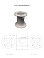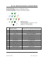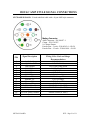
1
Sidewinder High Definition IP Cameras
SW720-H.264-HD
Installation and Operation Manual
Including:
Optional X30 Optical Zoom (HD30)
Optional Electric Brakes (ENG)
Optional Nitrogen Pressurization (P)
Optional Connector Interfaces (HV)(AMP)
120VAC and 24VAC Options
REVISION 04-06-15
TABLE OF CONTENTS
INFORMATION................................................................................................................................. 3
FCC NOTICE .................................................................................................................................. 3
READ THIS MANUAL.................................................................................................................. 3
PRODUCT WARRANTY AND REPAIR ........................................................................................... 4
PRODUCT WARRANTY.............................................................................................................. 4
REPAIR AUTHORIZATION ....................................................................................................... 5
RETURNS ....................................................................................................................................... 5
WARNING ...................................................................................................................................... 6
SAFEGUARDS .................................................................................................................................... 7
GENERAL DESCRIPTION................................................................................................................ 8
MODELS AND FEATURES ............................................................................................................. 9
INSTALLATION.............................................................................................................................. 10
RECOMMENDED TOOLS FOR PROPER INSTALLATION .............................................. 10
INSTALLATION PLANNING ................................................................................................... 10
DIMENSIONS AND MOUNTING................................................................................................... 11
MECHANICAL DIMENSIONS ................................................................................................. 11
MOUNTING ................................................................................................................................. 12
MOUNTING ACCESSORIES ........................................................................................................ 13
120VAC MS SIGNAL CONNECTIONS........................................................................................ 19
24 VAC MS STYLE SIGNAL CONNECTIONS .......................................................................... 20
120VAC AMP STYLE SIGNAL CONNECTIONS ...................................................................... 21
SIGNAL DESCRIPTIONS .............................................................................................................. 22
120VAC LINE CONNECTIONS ................................................................................................ 22
24VAC POWER CONNECTIONS............................................................................................. 22
ETHERNET SIGNAL CONNECTIONS ................................................................................... 22
ANALOG VIDEO CONNECTIONS .......................................................................................... 22
HARD WIRED PTZ SERIAL CONTROL PORT.................................................................... 22
RJ-45 SERIAL DATA BREAKOUT BOX ................................................................................ 23
CAMERA ETHERNET PROTOCOLS AND PORTS ................................................................. 23
CAMERA ETHERNET PROTOCOLS AND PORTS ................................................................. 24
DEFAULT IP ADDRESS............................................................................................................. 24
DEFAULT PORT ADDRESSES................................................................................................. 24
CAMERA PROTOCOL SUPPORT........................................................................................... 25
SURGE PROTECTION AND PRESSURIZATION .................................................................... 26
SEALING AND PRESSURIZATION ............................................................................................ 26
SPECIFICATIONS .......................................................................................................................... 27
X30 ZOOM IMAGE SENSOR AND LENS............................................................................... 27
X20 ZOOM IMAGE SENSOR AND LENS............................................................................... 27
VIDEO ENCODING .................................................................................................................... 28
CAMERA HOUSING MODULE ............................................................................................... 28
PAN AND TILT DRIVE ASSEMBLIES ................................................................................... 29
ELECTRICAL .............................................................................................................................. 30
ENVIRONMENTAL .................................................................................................................... 30
MECHANICAL ............................................................................................................................ 31
REVISION HISTORY ................................................................................................................. 31
SW720-H.264-HD
WTI ~ Page 2 of 31
INFORMATION
FCC NOTICE
This device complies with Part 15 of the FCC
Rules.
TOLL FREE. 866/gotowti (468-6984)
TEL. 805/339-9696
FAX. 805/339-0932
Operation is subject to the following two
conditions:
EMAIL: [email protected]
INTERNET: http://www.gotowti.com
1.) This device may not cause harmful
interference.
2.) This device must accept any interference
that may be received, including interference
that may cause undesired operation.
READ THIS MANUAL
Every effort has been made to insure that this
WTI system is of the highest quality. This
product has been carefully inspected to
comply with rigid quality standards before
shipment to you. In consideration of your
investment and the desire to obtain full
performance capability engineered into your
new WTI product, we recommend that you
read this manual before attempting to operate
your system.
FOR MORE ASSISTANCE OR MORE
INFORMATION
WTI (Wireless Technology, Inc.)
2064 Eastman Avenue, Suite 113
Ventura, CA 93003-7787
SW720-H.264-HD
The software / firmware furnished with the
equipment is confidential to and is
copyrighted by Wireless Technology, Inc.
(WTI) It is not to be copied or disclosed in any
manner without the consent of Wireless
Technology,
Inc.
(WTI).
The
software/firmware is furnished to the
purchaser under a license for use on a single
system.
Information
furnished
by
Wireless
Technology, Inc. (WTI) is believed to be
accurate and reliable. However, no
responsibility is assumed by Wireless
Technology, Inc. (WTI)for its use or for any
infringements of other rights of third parties,
which may result from its use. No license is
granted by implications or otherwise under
any patent or patent rights of Wireless
Technology, Inc. (WTI)
©2011 Wireless Technology, Inc. (WTI)
All rights reserved.
WTI ~ Page 3 of 31
PRODUCT WARRANTY AND REPAIR
PRODUCT WARRANTY
We appreciate your purchase of Wireless Technology, Inc. (WTI) security products. We
take pride in the quality of our products and have manufactured each new WTI product to
exacting quality standards. In normal use, it will provide you with years of satisfactory
performance. However, should you experience difficulty; you are protected under the
provisions of this warranty.
WTI warrants to the original user a product that is free of defects in materials and
workmanship in normal use. WTI warrants to the original user that WTI’s products will
be free of defects in materials and workmanship in normal use for a period of 24 months
from the date of sale. WTI’s obligation under this warranty shall be limited to the repair,
including all necessary parts and the cost of labor connected therewith, or at our option,
the replacement of any product that shows evidence of a manufacturing defect within the
warranty period. This warranty is extended to all WTI products purchased and used
within the United States of America and is valid only when service is rendered by the
authorized WTI (Wireless Technology, Inc.) Warranty Station.
This warranty shall not apply to appearance or accessory items including, but not limited
to, knobs, connectors, cabinets and connecting cables. This warranty shall not, in
addition, apply to repairs or replacements necessitated by any cause beyond the control of
WTI including, but not limited to, acts of nature, improper installation, misuse, lack of
proper maintenance, accident, voltage fluctuations, unauthorized repairs or modifications.
This warranty becomes void in the event serial numbers are altered, defaced or removed,
or an attempt is made to field service or alter performance of any WTI products.
WTI reserves the right to make changes in design, or to make additions to, or
improvements upon, products without incurring any obligation to install the same on
products previously manufactured.
The foregoing is in lieu of all other warranties expressed or implied and WTI neither
assumes nor authorizes any person to assume for it any other obligation or liability in
connection with the sale of our products. In no event shall WTI or its Authorized Dealers
be liable for special or consequential damage arising from the use of this product, or any
delay in the performance of this warranty due to causes beyond its control.
SW720-H.264-HD
WTI ~ Page 4 of 31
PRODUCT WARRANTY AND REPAIR
REPAIR AUTHORIZATION
Please contact Wireless Technology, Inc. (WTI), to obtain a repair authorization number
(RA) and provide the following information:
1.) Product Model & Serial Numbers
2.) Date of shipment, purchase order number, sales order number or WTI invoice
number.
3.) Details of the defect or malfunction. If there is a dispute regarding the warranty or
product, which does not fall under the warranty conditions stated within the
description of the written warranty, please include a written explanation with the
product when returned.
SHIP FREIGHT PRE-PAID TO:
WTI (Wireless Technology, Inc.)
2064 Eastman Avenue, Suite 113
Ventura, CA 93003-7787
TEL 805/339-9696
FAX 805/339-0932
RETURNS
No unauthorized returns will be accepted. All returns must have an authorized (RA)
number issued by the factory (CA number if returned for credit and RA number if
returned for repair). Products returned for repair or credit will be rejected if no
authorization number has been issued or freight has not been pre-paid. All merchandise
returned for credit will be subject to a 20% restocking and refurbishing charge.
SW720-H.264-HD
WTI ~ Page 5 of 31
PRODUCT WARRANTY AND REPAIR
WARNING
The Sidewinder series of IP66/IP67 rated cameras provide a fully sealed, moisture free
environment for the internal electronic and mechanical components. If the camera
housing cover or seals become compromised due to being struck by objects or damaged
during handling, the cameras should be taken out of service IMMIDIATELY, so that the
camera can be returned to WTI for repair. This will help prevent further EXPENSIVE
internal corrosion damage from occurring. Below are some examples of Damage that will
compromise the sealing integrity of the camera.
SW720-H.264-HD
WTI ~ Page 6 of 31
SAFEGUARDS
IMPORTANT SAFEGUARDS
1.) Read Instructions. It is important to read all safety and operating instructions
before installing or using this equipment.
2.) Retain Instructions. Retain this manual and any supplements for future reference.
3.) Follow Instructions. Follow all instructions herein for use of this equipment.
4.) Heed all warnings. Adhere to all warnings on the equipment, and in this manual.
5.) To reduce the risk of electric shock or equipment damage, work on the unit only
when the power is shut off and is unplugged from its power source to prevent
accidental activation. Also take precautions to avoid contact between the
equipment and other electrical wires or power sources that may be present at the
installation site.
SW720-H.264-HD
WTI ~ Page 7 of 31
GENERAL DESCRIPTION
The Sidewinder SW720-H264-HD is a pan-tilt-zoom camera system that provides high
definition color video in a variety of resolutions, up to 1080p30, over an Ethernet
connection, using H.264 or MJPEG video compression. The camera provides 360 degree
continuous rotation in both the pan and tilt axes, and provides an optical zoom
magnification of 20 times or 30 times. A self-cleaning hydrophilic coating is provided on
the front lens window of the camera to ensure clear, crisp video images and to reduce
maintenance. An electrically conductive Indium-Tin-Oxide coating is provided on the
inside of the front lens window to heat it and prevent fogging.
The Sidewinder SW720-H.264-HD camera operates on AC line voltages within a voltage
range of 85VAC to 265VAC and an operating frequency of 47Hz to 63Hz. Optional
24VAC power is also available (Side Egress Only). Ethernet 10/100Base-T
communication is used for transport of the video and control signals. Power and Ethernet
signals are provided via a 36 inch long bottom egress umbilical cable bundle using an
outdoor rated SJOOW #18x3 power cable, an outdoor rated shielded CAT-5e Ethernet
cable and an RG-59 video cable. The camera umbilical cable is terminated with an 18 Pin
MS style male connector or a 16 Pin AMP connector. An optional side egress connector
arrangement is also available.
The Sidewinder SW720-H264-HD camera is capable of supporting an H.264 and a
second H.264 or MJPEG compressed video stream simultaneously. Support is provided
for unicasting and multicasting.
The SW720-H264-HD camera provides Ethernet ports for support of industry standard
PTZ control protocols such as Pelco D, COHU, NTCIP, ONVIF and others. Legacy
support for physical camera control units can be implemented using serial port to
Ethernet converters.
Signals wiring for an RS-485 serial data port and analog NTSC video output are both
provided to support upgrading legacy camera installations or for replacing cameras with
similar signal interfaces from other manufacturers.
SW720-H.264-HD
WTI ~ Page 8 of 31
MODELS AND FEATURES
SW720-H.264-HD
x
x
x
x
x
x
x
x
x
x
x
x
x
x
x
x
x
x
x
x
x
x
x
x
x
x
x
x
x
x
x
x
x
x
x
x
x
x
x
x
x
x
x
x
x
x
ELECTRIC BRAKES
PRESSURIZATION
X30 ZOOM BLOCK CAMERA
X20 ZOOM BLOCK CAMERA
SIDE EGRESS MS
36 INCH AMP UMBILICAL
MODEL
SW720-H.264-HD
SW720-H.264-HD-ENG
SW720-H.264-HD30
SW720-H.264-HD30-ENG
SW720P-H.264-HD
SW720P-H.264-HD-ENG
SW720P-H.264-HD30
SW720P-H.264-HD30-ENG
SW720HV-H.264-HD
SW720HV-H.264-HD-ENG
SW720HV-H.264-HD30
SW720HV-H.264-HD30-ENG
SW720AMP-H.264-HD
SW720AMP-H.264-HD-ENG
SW720AMP-H.264-HD30
SW720AMP-H.264-HD30-ENG
SW720-24-H.264-HD
SW720-24-H.264-HD30
SW720P-24-H.264-HD30
36 INCH MS UMBILICAL
The Sidewinder High Definition IP cameras are available with several signal connector
arrangements, two different block cameras, optional electric brakes and optional
pressurization. The following table provides a quick reference to the major features
available in each camera model.
x
x
x
x
x
WTI ~ Page 9 of 31
INSTALLATION
RECOMMENDED TOOLS FOR PROPER INSTALLATION
1)
2)
3)
4)
Tie wraps to secure cable runs.
Set of open end wrenches including 7/16” for mounting bolts.
Cordless power drill for mounting some brackets.
Safety cable recommended (prevents camera falling during overhead
installations).
5) Self-sealing connector tape to weatherproof all cable connections.
INSTALLATION PLANNING
1) The maximum cable length that should be planned for is 100 meters, based on the
limit for 10/100Base-T Ethernet connections.
2) The Sidewinder SW720-H264-HD camera draws up to 50 Watts maximum,
which translates to about 0.59 Amps at the low line voltage limit of 85VAC.
3) Be sure to verify that there are no physical obstructions that might prevent the
camera from turning freely in all directions.
4) Be sure to verify that there are no physical obstructions in the way of any required
viewing directions.
5) Be sure that there is access to the end of the umbilical cable on the bottom of the
camera to facilitate connecting and disconnecting the camera while it is in place
on the mounting bracket or pole.
UNPACKING
Please examine the equipment carefully when unpacking the shipping container. If any
damage is noted please be sure to file a claim with the carrier. WTI is not responsible for
any damage that occurs during shipping. Please verify that all of the contents are present
and carefully check the packing material for any loose items before recycling it.
EQUIPMENT SUPPLIED WITH UNIT
1.) Camera
2.) 4 each ¼-20 x ¾” mounting screws with washers
3.) Quick Start Manual
EQUIPMENT THAT MAY BE REQUIRED, BUT NOT SUPPLIED WITH UNIT
1.)
2.)
3.)
4.)
5.)
6.)
Mating connector and strain relief for umbilical extension cable
Camera mounting bracket
Interconnect cables
Video monitor
PC or laptop computer
Setup software
SW720-H.264-HD
WTI ~ Page 10 of 31
DIMENSIONS AND MOUNTING
MECHANICAL DIMENSIONS
BOTTOM EGRESS
SIDE EGRESS
SW720-H.264-HD
WTI ~ Page 11 of 31
MOUNTING
The Sidewinder SW720-H264-HD camera should normally be mounted in an upright
orientation, as shown above. The camera may also be mounted upside down if desired,
but a cover of some sort should be placed over the bottom of the camera, extending out to
about 6 inches past the camera all around, to prevent debris, dirt or snow and ice from
accumulating on the bottom of the camera housing, since the conical shaped profile of the
camera will no longer be able to naturally shed material to the sides. The camera may
NOT be mounted with the base facing horizontally.
The base of the Sidewinder SW720-H.264-HD camera has four ¼-20 screw holes that are
equally spaced, 90 degrees apart, on a 4.75” diameter circle, as shown in figure 2 (Note
that 24VAC versions of the Sidewinder camera will have 5/16” mounting screws). If
mounting screws other than those provided with the camera are used, the length of the
mounting screws should be selected so that the screws penetrate no more than 0.75 inches
into the base.
SW720-H.264-HD
WTI ~ Page 12 of 31
MOUNTING ACCESSORIES
WTI manufactures several different mounts for the Sidewinder SW720A that allow the
camera to be attached to pole tops, horizontal poles, vertical poles and walls. The
Sidewinder SW720-H.264-HD camera is supplied with a 36 inch umbilical cable to allow
the cable to be routed through the camera mount before the actual physical installation of
the camera.
SWWM1 – Wall Mount Option
SW720-H.264-HD
WTI ~ Page 13 of 31
SWWM1 + SWVPA – Wall Mount with Vertical Pole Adapter
SW720-H.264-HD
WTI ~ Page 14 of 31
SWPTM1 – Pole Top Mount
SW720-H.264-HD
WTI ~ Page 15 of 31
SWHPM1 – Horizontal Pole Mount
SW720-H.264-HD
WTI ~ Page 16 of 31
15-4-1430 – 6”x6”x3/8” Square Mounting Plate
SW720-H.264-HD
WTI ~ Page 17 of 31
15-4-913 – 6”Round Riser Mounting Base
SW720-H.264-HD
WTI ~ Page 18 of 31
120VAC MS SIGNAL CONNECTIONS
The Sidewinder SW720-H.264-HD is provided with a 36 inch umbilical cable and is
available with an 18 pin MS Style connector at the end. The umbilical cable provides the
power and Ethernet data and control signals for the camera. The umbilical cable exits
through the bottom of the camera housing. These connector pin outs are for all SW720H.264-HD models except for 24VAC and AMP connector models.
Mating Connector
Female MS Connector - Style MIL-DTL-26482
Amphenol P/N MS3116F-14-18S
Shell Size 14 - 18 Contact Pattern
PIN
Signal Description
A
B
C
D
E
F
G
H
J
K
L
M
N
P
R
S
T
U
Wiring Color Code and Wire
Recommendations
Analog Video Shield
RG-59U Shield
Ethernet Tx+
Ethernet TxEthernet Rx+
AC Safety Ground
Ethernet Rx-
Orange/White CAT-5e
Orange CAT-5e
Green/White CAT-5e
SJOOW Green (18 AWG)
Green CAT-5e
Analog Video Output
RS-422 RX +
RS-422 RX RS-422 Data Shield
RS-422 TX RS-422 TX +
AC Line Neutral (low)
85-265 AC Line Input (high/hot)
RG-59U Center
Brown CAT-5e
Brown/White CAT-5e
CAT-5e Shield (Belden 1300A)
Blue/White CAT-5e
Blue CAT-5e
SJOOW White (18 AWG)
SJOOW Black (18 AWG)
SW720-H.264-HD
WTI ~ Page 19 of 31
24 VAC MS STYLE SIGNAL CONNECTIONS
SW720-24-H.264-HD - Side egress 18 Pin MS style connector
SW720-24-H.264-HD30 - Side egress 18 Pin MS style connector
SW720P-24-H.264-HD30 - Side egress 18 Pin MS style connector
Mating Connector
Female MS Connector - Style MIL-DTL-26482
Amphenol P/N MS3116F-14-18S
Shell Size 14 - 18 Contact Pattern
PIN
Signal Description
A
B
C
D
E
F
G
H
J
K
L
M
N
P
R
S
T
U
Wiring Color Code and Wire Recommendations
Chassis Ground
Ethernet TX+
Ethernet TX24 VAC - 1
24 VAC - 1
24 VAC - 2
Overall Shield Drain Wire
CAT-5 Orange/White
CAT-5 Orange
White 20 AWG Minimum
White 20 AWG Minimum
Black 20 AWG Minimum
Analog Video Shield
RS-422/485 RxRS-422/485TxData Ground
RS-422/485 Tx+
Ethernet RXAC Safety Ground
24 VAC - 2
Analog Video Output
RS-422/485 Rx+
Ethernet RX+
RG-59U Shield
CAT-5 Brown/White
CAT-5 Blue/White
Data Cable Shield
CAT-5 Blue
CAT-5 Green
Green 20 AWG Minimum
Black 20 AWG Minimum
RG-59U Center
CAT-5 Brown
CAT-5 Green/White
SW720-H.264-HD
WTI ~ Page 20 of 31
120VAC AMP STYLE SIGNAL CONNECTIONS
SW720AMP-H.264-SD - 36 inch umbilical cable with a 16 pin AMP style connector
Mating Connector
AMP Connector - P/N 206037-1
Clamp – P/N 1310307
16 Contact Pattern
Female Pins – 3 each – P/N 66565-4 - #20-24
Female Pins – 12 each – P/N 66109-4 - #24-26
PIN
Signal Description
Wiring Color Code and Gauge
Recommendations
1
2
3
4
5
6
7
8
9
10
11
12
13
14
15
16
Analog Video Output
Analog Video Shield
Data Ground
RS-485 TxRS-485 Tx+
RS-485 Rx+
RS-485 RxEthernet TX+
Ethernet TXEthernet RX+
Ethernet RX85-265 AC Line Hot
AC Line Neutral
spare
115 VAC Safety Ground
Spare
RG-59U Center
RG-59U Shield
Cat-5e Data Cable Shield
CAT-5e Blue/White
CAT-5e Blue
CAT-5e Brown
SW720-H.264-HD
CAT-5e Brown/White
CAT-5e Orange/White
CAT-5e Orange
CAT-5e Green/White
CAT-5e Green
SJOOW Black (18 AWG)
SJOOW White (18 AWG)
SJOOW Green (18 AWG)
WTI ~ Page 21 of 31
SIGNAL DESCRIPTIONS
120VAC LINE CONNECTIONS
The AC Line connections should be connected to an AC mains source with a voltage of
85VAC to 265V AC, operating at a frequency of 47Hz to 63Hz. The nominal operating
voltage is normally 115VAC or 230VAC. The camera draws 50 Watts maximum, which
translates to about 0.6 Amps at the worst case low line voltage of 85VAC. We
recommend SJOOW cable for these signals.
24VAC POWER CONNECTIONS
The 24VAC power connections require the use of heavier gauge wiring and shorter cable
lengths than the 120VAC power option, as the 24VAC camera model draws
approximately 5 times as much current through the cable wiring, due to the reduced
operating voltage. Four power connection terminals are provided on the MS connector to
allow paralleled power wiring. Cable runs of up to 150 feet require paralleled #20 AWG
wiring (equivalent to #17 AWG) for reliable operation. Longer runs should use
correspondingly larger wire gauges to minimize voltage drop along the cables. Runs of
300 feet can use #14 AWG wiring and runs of 500 feet can use #10 AWG or #12 AWG
wiring.
ETHERNET SIGNAL CONNECTIONS
The Ethernet signals should be connected using a CAT-5e or CAT-6 cable. If the legacy
serial data control port is to be used, the Ethernet cable should be the shielded type and
the Ethernet cable shield should be connected to the data shield signal. We recommend
Belden 1300A cable for these signals.
ANALOG VIDEO CONNECTIONS
An NTSC standard definition video signal output provides a 1Vpp NTSC video signal
with a 75 Ohm drive impedance. We recommend Belden 9259 RG-59/U cable.
HARD WIRED PTZ SERIAL CONTROL PORT
A secondary hard wired RS-485 port is provided on the SW720-H264-SD camera for
PTZ and other camera control functions. These signals can be conveniently accessed at
the cabinet end of the customer installed control cable by using the WTI RJ-45 Serial
Data Breakout Box.
There are internal 120 Ohm termination resistors for both the TX and RX signal pairs.
The factory shipped default state for the 120 Ohm terminations is for both the TX and RX
terminations to be enabled. Applications that involve multiple cameras on the same RS485 communications lines will require that the terminations on all cameras but one be
turned off.
SW720-H.264-HD
WTI ~ Page 22 of 31
RJ-45 SERIAL DATA BREAKOUT BOX
An RJ-45 Serial Data Breakout Box is available to facilitate legacy installations that
utilize the RS-485 signals available on the SW720-H.264-HD series of cameras. The RS485 signals are routed on the two unused pairs in the Ethernet CAT-5e or CAT-6 cable.
Note that shielded Ethernet CAT-5e or CAT-6 cable, like Belden 1300A, should be used
for these types of legacy installations. The breakout box is wired into the system at the
cabinet end of the Ethernet cable on the RJ-45 Ethernet plug. An input RJ-45 and Output
RJ-45 connector are provided on the breakout box for passing through the Ethernet data,
and a 5 Pin Phoenix style connector interface is provided for extracting the RS-485
signals from the Ethernet cable..
SW720-H.264-HD
WTI ~ Page 23 of 31
CAMERA ETHERNET PROTOCOLS AND PORTS
The PTZ camera control functions and video streaming functions to and from the
SW720-H264-SD camera are transmitted over a 100Base-TX Ethernet connection using
specific Ethernet ports are assigned for each of the various functions and protocols.
DEFAULT IP ADDRESS
The SW720-H264-SD camera default IP Address is: 192.168.1.251
DEFAULT PORT ADDRESSES
The following ports are provided for the various services available.
Protocol
Default Port
Default Transport
Notes
WTI
53935
UDP
NTCIP
55000
UDP
Pelco-D
55001
UDP
Sidewinder H.264 series
devices are fixed at multidrop
address 1.
Cohu
55002
UDP
Sidewinder H.264 series
devices are fixed at multidrop
address 1.
ONVIF
55003
TCP
UDP not supported. Server
shared with HTTP by default.
HTTP Server
55003
TCP
UDP not supported. Server
shared with ONVIF by
default.
Disabled by default on
Sidewider SW720 H.264
SD/HD. Enabled by default on
Sidewinder H.264 Video
Encoder.
Pass-Through
55004
UDP
WS-Discovery
3702
UDP Multicast
(group address
239.255.255.250)
RTSP Server
8554
TCP
UDP not supported
Multicast Video
RTP/RTCP
18888/18889
UDP Multicast
(group address
Only if video stream 1 is set
up for Multicast transport. A
SW720-H.264-HD
WTI ~ Page 24 of 31
Default Transport
Notes
(Stream 1)
random SSM)
static group address may also
be configured.
Multicast Video
RTP/RTCP
(Stream 2)
UDP Multicast
(group address
random SSM)
Protocol
Default Port
18890/18891
Only if video stream 2 is set
up for Multicast transport. A
static group address may also
be configured.
CAMERA PROTOCOL SUPPORT
The SW720-H264-SD camera supports COHU, Pelco D, WTI, NTCIP, Web/ONVIF and
other protocols through the RS-485 data connections. The RS-485 serial port can be
configured using the On Screen Menu system or by using the WTI Camera Control GUI
program through the Ethernet connection.
The various protocols can also be accessed through the use of different port numbers
when sending camera control commands to the Sidewinder using an Ethernet connection.
COHU Protocol:
55002
Pelco D Protocol:
55001
WTI Protocol:
53935
NTCIP Protocol:
55000
Web/ONVIF Protocol: 55003
As long as they are not used simultaneously, it is possible to use multiple different
protocols from different control stations when using the Ethernet protocol support. For
example, if COHU protocol is being used locally on the RS-485 serial data port, it is
possible to use NTCIP protocol over the Ethernet from the head end monitoring center to
control the camera on port 55000.
SW720-H.264-HD
WTI ~ Page 25 of 31
SURGE PROTECTION AND PRESSURIZATION
SURGE PROTECTION
The SW720-H264-HD camera provides internal surge protection for all of the power,
data and video signals.
1.) The AC line power connections are provided with 275 volt 135 Joule MOV surge
arrestors rated for 6000 Amp pulses. A 3A SMT fuse is included in the primary
circuit to prevent catastrophic printed circuit board damage in the case of gross
AC line input overloads.
2.) The video signal lines incorporate a two stage protection circuit consisting of a
primary 90V gas discharge tube, followed by a high speed, low capacitance 6.2V
2kW peak power transient voltage suppressor.
3.) The data signal lines incorporate a two stage protection circuit consisting of a
primary 90V gas discharge tube, followed by an 18V, 300W, 40A transient
voltage suppressor.
SEALING AND PRESSURIZATION
The SW720-H264-HD camera provides two levels of sealing and pressurization. The
entire camera, including the base, housing and camera tube are all sealed to IP66/67
levels to prevent any ingress of dust or moisture. An additional option is available, in
which the camera housing tube is pressurized to 5 psi with dry nitrogen gas.
The SW720-H264-HD camera with the pressurization option is provided with a Schrader
valve to allow periodic replenishment of the dry Nitrogen in the camera housing tube.
Since no sealing system will remain 100% airtight indefinitely, it may be necessary to
replenish the dry Nitrogen occasionally. This can be done at the same time that the
regular camera cleaning is performed. A 15psi pressure relief safety valve is provided to
prevent damage to the seals and to prevent blowing out the front or back plates of the
camera housing if an unregulated high pressure dry Nitrogen tank were to be connected
to the Schrader valve.
SW720-H.264-HD
WTI ~ Page 26 of 31
SPECIFICATIONS
X30 ZOOM IMAGE SENSOR AND LENS
Image Sensor Type
Solid State EXMOR CMOS Progressive Scan
Image Sensor Size
1/2.8” inch type
Pixel Resolution
2144 horizontal x 1588 vertical (total) – 2096(H) x
1561(V) viewable
Video Output Format HD: 1080P30 at full resolution
Maximum Lens Aperture
F1.6 at full wide angle – F4.7 at full telephoto
Optical Zoom Range
x1 to x30
Focal Length
4.3mm ~ 129mm
Digital Zoom Range
x1 to x12 with smooth transition from optical to digital
Combined Focal Length
4.3mm ~ 1548mm
Optical Zoom Speed
0.8sec
Horizontal Angle of View
63.7 degrees (wide angle) to 2.3 degrees (tele)
Minimum Focus Distance
0.4 inches (wide angle) to 40 inches (tele)
Electronic Stabilization
10Hz
Auto Focus
Selectable between Auto/Manual
Manual Focus Speed
3.2sec Tracking Off – 4.6sec Tracking On
Shutter Speed
Adjustable from 1 second to 1/10,000 second. Settings
below 1/60 second increase integration time to improve low
light sensitivity with video frame store to provide
continuous video output.
Auto Iris
16 Steps
AGC Range
0dB to 28dB – 1dB steps
Minimum Illumination
0.35lux (1/30sec,50IRE, High SENS.)
Color Balance
AUTO, ATW, Indoor, Outdoor, OnePush WB, Manual
WB, Outdoor Auto, Sodium Vapor Lamp.
Gamma
Normal, Straight
Signal to Noise Ratio
>50dB
Synchronization
Crystal
Features
EIS, De-Fog, Visibility Enhancement, Noise Reduction,
Backlight Compensation, High Sensitivity Mode, Color
Enhancement, Stable Zoom, IR Cut Filter, Wide Dynamic
Range
X20 ZOOM IMAGE SENSOR AND LENS
Image Sensor Type
Solid State EXMOR CMOS Progressive Scan
Image Sensor Size
1/2.8” inch type
Pixel Resolution
2144 horizontal x 1588 vertical (total) – 2096(H) x
1561(V) viewable
Video Output Format HD
1080P30 at full resolution
Maximum Lens Aperture
F1.6 at full wide angle – F3.5 at full telephoto
Optical Zoom Range
x1 to x20
Focal Length
4.7mm ~ 94mm
SW720-H.264-HD
WTI ~ Page 27 of 31
Digital Zoom Range
Combined Focal Length
Optical Zoom Speed
Horizontal Angle of View
Minimum Focus Distance
Electronic Stabilization
Auto Focus
Manual Focus Speed
Shutter Speed
Auto Iris
AGC Range
Minimum Illumination
Color Balance
Gamma
Signal to Noise Ratio
Synchronization
Features
VIDEO ENCODING
Video Encoding
Video Streams
Codec
Image Resolution
Streaming Mode
Image Settings
Frame Rate
Data Rate
Connection Types
Video Latency
Network Protocol Layers
x1 to x12 with smooth transition from optical to digital
4.7mm ~ 1128mm
0.8sec
55.4 degrees (wide angle) to 2.9 degrees (tele)
0.4 inches (wide angle) to 40 inches (tele)
None
Selectable between Auto/Manual
1.6sec Tracking Off – 2.3sec Tracking On
Adjustable from 1 second to 1/10,000 second. Settings
below 1/60 second increase integration time to improve low
light sensitivity with video frame store to provide
continuous video output.
16 Steps
-3dB to 28dB – 16 steps
0.5lux (1/30sec,50IRE, High SENS.
AUTO, ATW, Indoor, Outdoor, OnePush WB, Manual
WB, Outdoor Auto, Sodium Vapor Lamp.
Normal, Straight
>50dB
Crystal
Noise Reduction, Backlight Compensation, High
Sensitivity Mode, Color Enhancement, IR Cut Filter, Wide
Dynamic Range
H.264 (Baseline, Main, High Profiles, up to Level 4),
MJPEG and MPEG-4 standards
Two independently configurable streams; (2) H.264
streams or (1) H.264 and (1) MJPEG or (1) MPEG-4 and
(1) MJPEG
Video Stream 1: H.264 or MPEG-4
Video Stream 2: H.264 or MJPEG
1080p, 720p, D1, VGA, 2CIF, HVGA, QVGA
CBR or VBR
GOP (M, N), Quality Value, Slice Mode
30, 15, 7, 4, 2, 1, (M, N)
Adjustable from 64k to 12 Mbps in VBR mode and 64k to
16 Mbps in CBR mode.
Unicast, multi-unicast or multi-cast
<250ms
RTP, RTSP, UDP, TCP, IP, HTTP, IGMPv2, ICMP, ARP
as a minimum
CAMERA HOUSING MODULE
SW720-H.264-HD
WTI ~ Page 28 of 31
External Window Coating
High temperature vacuum deposited hydrophilic coating to
reduce window cleaning maintenance.
Internal Window Coating
Electrically conductive coating to allow energy saving
direct heating of window glass to prevent fogging.
Window Heat Control
Proportionally controlled closed loop window heater drive
circuit with outside temperature sensor unit to provide fog
free window operation under all environmental conditions.
Block Camera Heating
Temperature sensor and microprocessor controlled image
sensor heater to provide reliable operation of zoom lens
down to -34 degrees Celsius.
PAN AND TILT DRIVE ASSEMBLIES
Drive Range
360 degrees continuous rotation (both axes)
Drive Speed
Variable from 0.0003 Deg/Sec to 100 Deg/Sec
Drive Resolution
0.005625 Degrees
Drive Repeatability
0.05 Degrees typical
Preset to Preset Time
Selectable between 2 seconds and 5 seconds for 180 degree
motion in both axes
Operator Motion Speed
Pan and Tilt speeds are proportional to both operator speed
commands and camera zoom setting.
Brakes
Optional electrically operated pan and tilt motor brakes
with a minimum holding torque of 300 oz./in available to
maintain the camera position when power is removed from
the camera.
Presets
Minimum of 64 presets, each preset to store variable data
for pan position, tilt position, zoom setting, focus setting
and 24 characters of titling text to be displayed when the
preset is recalled. Preset titling to remain on screen until
subsequent preset or camera control commands are
received.
Tours
Eight tours of up to 32 presets each shall be supported.
Presets may be assigned to the tours in any order and may
be used multiple times within one tour.
Panning Tours
Any or all of the eight tours may be used as “panning”
tours by selecting exactly two presets for the tour. The first
preset selected for the tour shall set the counter-clockwise
panning limit and the tilt angle for the tour, and the second
preset selected shall set the clockwise panning limit for the
tour. The positioning system shall pan smoothly from one
preset to the other and back again until a subsequent
camera command is received.
SW720-H.264-HD
WTI ~ Page 29 of 31
Sector Zones
Privacy Zones
Low Pressure Warning
Temperature Warning
Program Memory
ELECTRICAL
AC Line Voltage
Power Consumption
Analog Video Output
Video Transient Protection
Control Data
Data Transient Protection
Control Data Protocol
Power interrupt immunity
Power transient immunity
Interface connector
ENVIRONMENTAL
Ambient Temp. Limit
Humidity
Protection Rating
Air Contaminants
Vibration
Shock
Water Spray Immunity
SW720-H.264-HD
Up to 16 sector zones with user settable right and left pan
limits may be programmed with one line of up to 20
characters of ID titling per zone.
Any Sector Zone may be utilized as a privacy zone by
setting the video mode to “OFF” within that zone.
Provides low pressure warning indicator on video display
for cameras supplied with pressurized camera housing
option.
Provides an internal temperature warning indication on the
video display.
Unit is field upgradable using FLASH non-volatile memory
to store programming.
85-265 VAC 50/60 Hz
<50W with all options operating
75 Ohm, 1Vpp, NTSC, EIA-170A
Gas discharge tube followed by 40A 2kW transient voltage
suppressor.
EIA RS-485 signal levels and drive capabilities.
Gas discharge tubes followed by 40A 300W transient
voltage suppressors.
Cohu, Pelco D, WTI, NTCIP, ONVIF and others
NEMA TS-2 paragraph 2.1.4.
NEMA TS-2 paragraph 2.1.6.
MS style 18 Pin weatherproof and corrosion resistant type
with gold plated contacts or AMP style 16 pin type with
gold plated contacts.
-29° F to +165° F (-34° C to +74° C)
(Conforms to NEMA TS-2 paragraphs 2.1.2, 2.1.3 and
2.1.5.)
100% relative humidity
IP-67/NEMA-4X/ASTM-B117 (entire camera)
Withstands exposure to sand, dust, fungus,
salt atmosphere, per MIL-E-5400T,
paragraph 3.2.24.7, 3.2.24.8, and 3.2.24.9
NEMA TS-2 paragraphs 2.1.9 and 2.2.3 using a 0.5g
amplitude signal from 5Hz to 30Hz applied in each of 3
mutually perpendicular axes for 30 minutes.
NEMA TS-2 paragraphs 2.1.10 and 2.2.4 using a 10g
amplitude, 10ms duration shock pulse in each of three
mutually perpendicular axes.
IPx6 rating - IEC 60529 section 14.2.6 using a 25 gallon
per minute water stream through a 12.5mm nozzle at nine
feet for three minutes.
WTI ~ Page 30 of 31
Water Immersion Immunity IPx7 - IEC 60529 section 14.2.7 using an immersion depth
of 1 meter measured at the bottom of the camera and a
duration of 30 minutes.
Icing Immunity
NEMA 250-2003 section 5.6.
Corrosion Immunity
NEMA 250-2003 section 5.10 and the procedure specified
in ASTM-B117 Marine.
EMI Radiation
Within the limits set by FCC Regulations 47 CFR Part 15
for Class A devices.
MECHANICAL
Dimensions
Weight
Construction
12.6”L x 11.3”H x 9.25”W (32cm x 29cm x 20cm)
14.6 lbs. (6.64 kg.)
White powder coated aluminum and Kydex 550 with all
stainless steel hardware
REVISION HISTORY
01/15 – Update: Video Encoding Section
Added: IP66/IP 67 Broken Seal Warning
12/14 – Changed logo
11/14 – Add: Additional mounting options
6/14 – Added: Specification section at end of document, multiple model numbers to title
page, model feature matrix, AMP connector pin outs, RJ-45 Breakout Box, 24VAC
wiring diagrams, Ethernet address and port data.
11/13 – Analog video and RS-485 signal wiring in MS umbilical connector wiring chart
changed to standard, rather than optional. Mechanical dimensions drawing modified to
show umbilical connector with standard 3 foot length, rather than AC Plug and RJ-45
Connector.
SW720-H.264-HD
WTI ~ Page 31 of 31