1
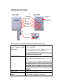
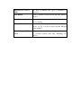
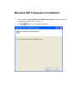
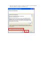
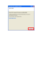
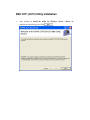
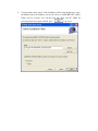
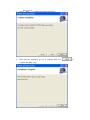
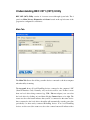
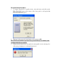
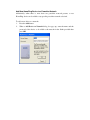
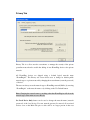
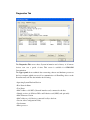
BEC 2071
HomePlug AV 200 Ethernet Adapter
BEC 2072
HomePlug AV 200 Ethernet Bridge
with AC Pass-Through
User Manual
Table of Contents
Product Introduction .....................................................................................3
Features & Specifications .............................................................................3
Getting Started ...............................................................................................5
Features - HomePlug AV 200 Ethernet Bridge .................................................... 5
Hardware Overview ........................................................................................... 6
Sync Button Function:................................................................................. 8
HomePlug AV 200 Application Scenarios:................................................... 8
Application Illustration...............................................................................10
BEC 2071 (2072) Utility Installation Procedures........................................ 11
Microsoft .NET Framework 2.0 Installation ......................................................13
BEC 2071 (2072) Utility Installation .................................................................16
Starting BEC 2071 (2072) Utility..................................................................19
Understanding BEC 2071 (2072) Utility............................................................20
Main Tab....................................................................................................20
Password Setup Procedure:............................................................22
Add New HomePlug Device to a Powerline Network ...................23
Privacy Tab ................................................................................................24
Diagnostics Tab..........................................................................................26
About Tab ..................................................................................................28
Troubleshooting...........................................................................................29
Product Introduction
BEC 2071 / 2072 is a networking device that utilizes the existing wiring system as a
path to transmit data signal through the inter-conversion between digital and analog
signal. With this functionality, BEC 2071 / 2072 can be plugged into an electrical
socket to draw power and at the same time establishing a network connection between
two or more Ethernet devices.
The BEC 2071 / 2072 can be used to bridge any Ethernet device to your Powerline
network in your home or office. With this technology, Ethernet devices in your home
or office can equally share high speed data transmission rate without the need to
spend excessive time and money installing expensive Ethernet cable. It can be
plugged into an Ethernet port on a router to equip a network with Powerline
capabilities and take advantage of the router features. The BEC 2071 / 2072 can also
be plugged directly into a cable or DSL modem that allows instant internet access
over home Powerlines to each computer equipped with a HomePlug AV certified
Powerline network adapter. BEC 2071 / 2072 makes high-speed modem sharing as
fast and simple as plugging the devices in the wall.
Features & Specifications
Protocol
TDMA, CSMA/CA
Standard
Ethernet specification: IEEE 802.3, IEEE 802.3x,
IEEE 802.3u, Auto MDI/MDIX
Transmission speed
200Mbps
Optimal Coverage Range
200M
Modulation
Supports OFDM - 1155 carriers,1024 / 256/64
QAM, QPSK, BPSK and ROBO
Frequency Band
2MHz ~ 30MHz
Security
128-bit AES encryption over household power
supplier grid
Device port
Ethernet RJ-45
Operation System
• Windows 98_SE / Me / 2000 /XP(32 and 64 bit)/
Vista (32 and 64 bit)
RAM
128Mb
Power Supplier
• Input: 100~240V AC, 50~60Hz
Specification
Physical Interface
• Interface: Ethernet 10/100M (MDI/MDIX) switch
• Sync button
• Reset button
• Power AC Plug (for BEC 2071 only)
• Power AC socket (for BEC 2072 only)
• LED display:
- 1.0 DET LED
- POWER LED
- PLC (Powerline Link/Act) LED
- ETH (Ethernet Link/Act) LED
Dimension
BEC 2071: 112.35 X 77.70 X44.50 mm
BEC 2072: 165 X 73 X 38.50 mm
Power Saving
Reduce power consumption by at least 60% during
power saving mode.
Operating Temperature /
Humidity
• Operating temperature: 0 ~ 400C
• Storage temperature: -20 ~ 700C
• Humidity: 5~95% non-condensing
Getting Started
Safety Warnings
1.
Do not use the adapter in high humidity or high temperature environment.
2.
Do not open or repair the case yourself.
3.
Avoid using this product and all its accesories outdoor.
4.
5.
Place the adapter on a stable surface.
Only “HomePlug AV” compliant Powerline Communication (PLC) adapter for
remote access is necessary.
Features - HomePlug AV 200 Ethernet Bridge
1.
2.
3.
4.
5.
6.
7.
8.
9.
Physical layer data rate up to 200Mbps over existing Powerline.
Uses powerline technology that takes advantage of the unused bandwidth of the
electrical wiring in the home.
Ideal for Triple Play applications such as IPTV, VoIP telephony and high-speed
Internet access.
Support 10/100 (MDI/MDIX) Ethernet switching.
Compliant with the HomePlug Powerline Alliance Industry specification
HomePlug AV.
Power supplier design inside.
Ideal for Residential Users.
Power Saving mode: When PC or other Ethenet devices are completely power
off, BEC HomePlug device will automatically enter power saving mode which
will help to reduce power consumption by at least 60%.
Noise Filter (only available in BEC 2072): Allow the filtering of noise which
may be generated by some electrical appliances such as vacumn cleaner and hair
dryer to prevent possible interference with HomePlug AV network.
Hardware Overview
BEC 2071
BEC 2072
1.0 DET LED
Power LED
PLC LED
AC Outlet / AC
Pass-thru
(only available in
BEC 2072 model)
ETH LED
Sync Button
Reset Button
Ethernet Port
Power Plug
The Description of each labeled part is described in the table below.
AC Outlet / AC Pass-thru Enable the plugging in of another Ethernet device for
(only available in BEC direct power supply.
The AC Pass-thru allows the filtering of noise to
2072 model)
prevent HomePlug AV Network interference.
Note: The AC Outlet only support devices that use
6A (maximum) electric current.
1.0 DET LED
Blink when detect the presence of other HomePlug 1.0
devices that have the transmission rate of 14 or 85
Mbps.
Note: Due to the incompatibility of HomePlug AV
200 with HomePlug 1.0 devices, the presence of the
HomePlug 1.0 devices within the powerline network
will thus reduce the performance of your powerline
network.
Power LED
Lit when the device is power on.
PLC (Powerline Link/Act) Lit when a network has been established. Blink when
powerline data is transmitted or received.
LED
ETH (Ethernet Link/Act)
Lit when an Ethernet data signal is transmitted or
LED
received.
Sync Button
Used to establish a LAN network with other Ethernet
devices.
Reset Button
Press this button to restore the device configuration to
factory default.
Ethernet Port
Connect the HomePlug AV device with an Ethernet
device (eg. PC or modem router) with the Ethernet
cable included.
Power Plug / AC Power Plug into an electric socket to draw power and to form
a powerline network with other HomePlug AV
Cord
devices.
Sync Button Function:
There are 3 types of Sync Button trigger states:
1.
Broadcast State: A BEC 2071 / 2072 device can provide information for
another BEC 2071 or 2072 device to join its powerline network group (works
even if it is currently the only device existing within the network group).
2.
3.
Join State: For an ungrouped BEC 2071 or 2072 device to join an existing
powerline network group.
Press the Sync Button on the first BEC 2071 / 2072 device to turn it to Broadcast
State. Then press the Sync Button of an ungrouped BEC 2071 / 2072 device to
turn it to a Join State.
4.
Ungroup State: Press the Sync Button for more than 10 seconds to separate the
device from its current attached network group.
HomePlug AV 200 Application Scenarios:
Scenario 1: A BEC 2071 / 2072 device A wants to form a network group with
another BEC 2071 / 2072 device B.
You can allocate whichever device (A or B) to be the Broadcast State and the Join
State.
Example:
1. Hold down the Sync Button of device A for 1~3 seconds to turn it into Broadcast
2.
3.
State.
Hold down the Sync Button of device B for 1~3 seconds to turn it into Join State.
Wait for the Sync LED of both devices to light up then you will now have both
devices being in the same network group.
Note: Once the device is plugged into the electric socket, connect it with an
Ethernet cable within 60 seconds to prevent the device from Auto Power Off.
Scenario 2: A BEC 2071 / 2072 device wants to join an existing network
group BC
Device A wants to join a network group “BC” currently consisting of device B
and device C. Any devices within the “BC” group can become the “Broadcast
State” and device A will be the “Join State”.
Example:
1.
Hold down the Sync Button of device B or C of the BC network group for 1~3
seconds to turn it into Broadcast State.
2.
3.
Hold down the Sync Button of device A for 1~3 seconds to turn it into Join State.
Wait for the Sync LED of both devices A and (B or C) to light up then you will
now have device A join the BC network group.
Note: Once the device is plugged into the electric socket, connect it with an
Ethernet cable within 60 seconds to prevent the device from Auto Power Off.
Scenario 3: A BEC 2071 / 2072 device A of network group AD wants to join
an existing network group BC.
For a device which already belongs to a network group is to join with a different
network group, that device has to be ungrouped from its current attached group
first.
1.
2.
3.
4.
Example:
Hold down the Sync Button of device A for more than 10 seconds to ungroup it
from network group AD.
Then hold down the Sync Button of device (B or C) of network group BC for
1~3 seconds to turn it to Broadcast State.
Hold down the Sync Button of device A again for 1~3 seconds to turn it to Join
State.
Wait for the Sync LED of both devices A and (B or C) to light up. Now you will
have device A join the network group BC.
Note: Once the device is plugged into the electric socket, connect it with an
Ethernet cable within 60 seconds to prevent the device from Auto Power Off.
Application Illustration
Home / Office Setting
BEC 2071 (2072) Utility
Installation Procedures
1.
Place
the
BEC
2071/BEC
2072
auto-installation
CD
into
CD-ROM/DVD-ROM drive and click on Utility for Easy Installation.
your
2.
If you have not installed Microsoft .NET Framework 2.0, click on Install
Microsoft .NET Framework 2.0 to install this program first before installing
BEC 2071 (2072) Utility.
3.
4.
If you have already had Microsoft .NET Framework 2.0 installed, please click
on Install the utility for Windows (32-bit / 64-bit) and proceed to the section
on BEC 2071 (2072) Installation.
If you are using Windows Vista operating system, do not have to install
Microsoft .NET Framework 2.0. Simply click on Install the utility for
Windows (32-bit / 64-bit) and proceed to the section on BEC 2071 (2072)
Installation.
Microsoft .NET Framework 2.0 Installation
1.
After clicking on Install Microsoft .NET Framework 2.0, the Net Framework
2.0 installation wizard will be displayed.
2.
Click
to proceed with the installation.
3.
Check the Agreement acceptance box then press Install to start the installation.
When the installation is complete, click Finish to exit.
BEC 2071 (2072) Utility Installation
1.
After clicking on Install the utility for Windows (32-bit / 64-bit), the
installation wizard will appear. Click
2.
You may define the location of the installation folder using the Browser or use
the default location. In addition, you can also choose to install BEC 2071 (2072)
Utility only for yourself or for all the users who share your PC. When all
necessary items are properly selected, press
to proceed.
3.
Press
to confirm and start the installation.
4.
Wait until the installation process is complete then press
complete the utility setup.
to
Starting BEC 2071 (2072) Utility
Once the BEC 2071 (2072) Utility Setup Wizard is installed, a shortcut will appear
on the desktop. You can start the BEC 2071 (2072) Utility by double clicking on the
shortcut, or go through “start”→ “All Program”→ “BEC 2071 (2072) Utility”
→“BEC 2071 (2072) Utility”.
Understanding BEC 2071 (2072) Utility
BEC 2071 (2072) Utility consists of 4 screens accessed through 4 panel tabs. The 4
panels are Main, Privacy, Diagnostics and About located on the top left corner of the
program for configuration convenience.
Main Tab
The Main Tab Screen lists all the powerline devices connected to the host computer
when the utility is running.
The top panel shows all local HomePlug devices connected to the computer’s NIC
(Network Interface Card). Normally, only one device will be seen. If there is more
than one local device being connected (eg. USB / Ethernet adapter), user can select
the local device by clicking on it and then click the Connect button to its right. The
status area above the button indicates that your PC is connected to that same device.
Once connected to the local device, the utility will automatically scan the power line
periodically for other newly connected HomePlug devices. If no local HomePlug
devices are discovered, the status area above the connect button will indicate with a
message ‘NO HOMEPLUG ADAPTERS DETECTED’.
The lower panel displays all the HomePlug remote devices, detected on the current
network. The total number of remote devices connected on the same network can be
found on top of the Remote device panel.
The Network type (Public or Private) is also displayed based on the network status of
the local device. The scan status option is displayed on the top right corner above the
Remote devices panel showing whether the Autoscan function is turned ON or OFF.
The following information is displayed for all devices that appear in the lower panel:
Device Name:
Show the default device name. User can change the name by either clicking on the
rename button or by clicking on the name and editing in-place. An icon is usually
shown with the device name.
Password (*required when creating a private network)
This column is left blank by default. The password will be displayed only after it has
been created. For detail information on password setup, please refer to section on
Password Setup Procedure.
Rate (Mbps):
Display the data transmission rate of each device.
MAC Address:
Show the Remote device MAC address.
Quality:
Display the overall quality of the data transmission rate. When the transmission rate is
good, the number of line appear will increase.
Password Setup Procedure:
1. To assign a password to a specific device, select the device and click on the
Enter Password button at the bottom of the lower panel to call up the Set
Device Password dialog box.
2. Then type in the password in the blank provided and press OK.
Note: The Password field accepts the Device password in any case formats, with
or without dashed between them.
3. If the password entered is not recognized or unacceptable, an error message box
will pop up prompting user to change the password.
Add New HomePlug Device to a Powerline Network
Additionally, when there is more than one powerline network present, a new
HomePlug device can be added to any specific powerline network as desired.
To add a new device to a network:
1.
2.
Press the Add button.
When a Add Device to Network dialog box pops up, enter the name and the
password of the device to be added to the network in the blank provided then
press OK.
Privacy Tab
Privacy Tab is to allow user the convenience to manage the security of the private
powerline network and to enable the adding of new HomePlug device to the private
network.
All HomePlug devices are shipped using a default logical network name
“HomePlugAv”. The Privacy tab screen allows user to change its default public
network type to a private network by changing the network name (network password)
of devices.
The user can always reset the network type to HomePlug network (Public) by entering
“HomePlugAv” as the network name or by clicking on the Use Default button.
Note: Changing the network name to anything other than HomePlugAv will show the
network type on the main screen as Private.
Set Local Device Only button can be used to change the network name (network
password) of the local device. If a new network password is entered, all associated
devices seen on the Main Tab prior to this will be no longer present in the new
network, rendering the local device unable to communicate with other devices in its
previous network.
Set All Devices button is used to change the logical network of all devices that appear
on the Main tab screen whose Device Password had been entered for the same logical
network. A dialog window will appear to report the success of this operation. For
devices whose device passwords were not entered, this operation will fail and will
report a failure message.
Diagnostics Tab
The Diagnostics Tab screen shows System information and a history of all remote
devices seen over a period of time. This screen is available for OEM/ODM
Customization.
The Upper panel shows technical data concerning software and hardware present on
the host computer which were used for communication via HomePlug device on the
Powerline network. The data includes the following:
• Operating System Platform/Version
• Host Network Name
• User Name
• MAC Address of all NICs (Network interface card) connected to the host
• Identify versions of all Driver DLLs and Libraries used (NDIS) and optionally
• MAC Firmware Version
• MAC addresses of all devices connected locally to the host
• Version of the Configuration Utility
• Vendor name
• Microprocessor
The Lower panel contains a history of all remote devices seen on the computer over a
certain period of time. All devices that were on the powerline network are listed here
along with a few other parameters. Devices that are active on the current logical
network will show a transfer rate in the Rate column; devices on other networks, or
devices that may no longer exist are shown with a “?” in the Rate column. The
following remote device information is available from the diagnostics screen:
• Device Alias Name
• Device MAC Address
• Device Password
• Device Last known rate
• Device Last Known Network name
• Vendor name
• Date device last seen on the network
• MAC Firmware version
• Number of dropped connections
• Number of loss connection
• The highest transmission rate recorded
• The lowest transmission rate recorded
• Total data sent
The diagnostics information displayed may be saved to a text file for later use, or can
be printed for reference for a technical support call. Devices, which are not part of the
network anymore, can be deleted using the delete button. A dialog window pops up
with a confirmation message if we try to delete a device whose password has been
entered.
About Tab
The About screen shows the software version and provides the HTML link to the
BEC official website. Clicking on the web address field will open a web browser that
link directly to the web site.
Under the Preferences panel, user can check the AutoScan box to turn on the Auto
Scan function or check off the box to turn off the Auto Scan function.
Troubleshooting
Problem:
My Homeplug device is unable to detect my other HomePlug device.
Solution:
This may due to the accidental change of the device password. Access the
HomePlug AV Utility and select the Privacy Tab. Enter the password
“HomePlugAV” (Case Sensitive) in the blank provided. Then press the “Set to
Local Device Only” button. Repeat the same procedure to the other
HomePlug device.