1
DPR 404
User Manual
1
V3.0
JMK
26 July 1999
This equipment has been tested and found to comply with the following European Standards for
Electromagnetic Compatibility:
Emission Specification:
EN55013
(1990)
(Associated equipment)
Immunity Specification:
EN50082/1
(1992)
(RF Immunity, Fast Transients and ESD)
Mains Disturbance:
EN61000/3/2
(1995)
For continued compliance ensure that all input and output cables are wired with cable screen connected to Pin
1 of the XLR. The input XLR Pin 1 on BSS equipment is generally connected to chassis via a capacitor to
prevent ground loops whilst ensuring good EMC compatibility.
We have written this manual with the aim of helping installers, sound engineers and musicians alike get to
grips with the DPR-404 and obtain its maximum capability.
If you are new to BSS products, we recommend that you begin at the start of the manual. If, however, you are
already familiar with the intended application, and just want to get the unit installed without delay, then
follow the highlighted sections.
We welcome any comments or questions regarding the DPR-404 or other BSS products, and you may contact
us at the address or World Wide Web site given in the warranty section.
2
Contents
Contents
1.0
The BSS DPR-404
5
2.0
Unpacking
6
3.0
Mechanical Installation
6
4.0
Earthing Requirements
7
5.0
Mains Power Connection
8
7.0
Audio connections
7.1
7.2
7.3
7.4
8.0
8.1
8.2
8.3
8.4
8.5
8.6
8.7
8.8
8.9
8.10
8.11
9.0
9.1
9.2
9.3
9.4
9.5
9.6
10.0
10.1
10.2
12
Balanced wiring
Unbalanced wiring
Ground loop control
Linked operation
Controls
12
12
12
13
14
IN
Gain
Ratio
Attack/Release
Below TH meter
Gain reduction meter
De-ess
FREQ
Link
Link master LED
Main power fuse
Rear panel controls
14
14
14
14
14
14
14
14
15
15
15
16
Mains voltage selector switch
Mains power switch
Mains voltage selector switch
External side chain insert
Electronically balanced input
Electronically balanced and floating output
Compressors and Limiters
The need for Gain Control
Compressors and Limiters
16
16
16
16
16
16
17
17
18
3
Contents
11.0
11.1
11.2
11.3
Compression
Attack, Release and Ratio
De-essing
20
20
21
22
12.0
Specifications
23
13.0
Service Section
25
13.1
13.2
14.0
4
The effect of Compression on
sound
Transient suppressor replacement
Separating signal and chassis ground
Warranty Information
25
26
27
The DPR-404
1.0
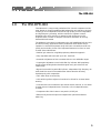
The BSS DPR-404
The DPR-404 is a compact and professional four channel compressor and deesser. Based on the well established BSS subtractive gain reduction principle,
it offers you four independent channels of high quality, musical compression
and high frequency de-essing, with the minimum of operator controls.
Designed to be quick and easy to operate by both skilled and novice
engineers alike, it makes a compact economical alternative to the fully
featured DPR-402 model.
The DPR-404 is the natural complement to the well established DPR-402 unit
and will find many applications within professional audio where ease of
operation is considered important along with lower cost without sacrifice to
quality and musicality. Some of the important features to be found on each
channel of the DPR-404 are:
• 30dB of gain reduction using BSS proprietary subtractive approach.
• Fully adjustable soft knee ratio up to 20:1 hard limit.
• Automatic adjustment of time constants with two user definable ranges.
• Output gain adjustment control with LED clip indicator. BSS proprietary
activity meter showing below threshold signal level, gain reduction and
usable range.
• Bypass in/out switching with LED indicator. Independent high frequency deesser threshold control and tuneable filter allows selective de-essing
simultaneously with compression.
• Twin LEDs show de-ess activity.
• Link switching allows adjacent channels to be linked for accurate stereo
working.
• One DPR-404 can be selected to process two stereo channels, or one stereo
channel and two independent mono channels, or four independent mono
channels.
• Compressor side chain insert on rear panel 1/4" RTS jack.
• Electronically balanced inputs and outputs with optional transformer
balancing.
5
Unpacking
Mechanical Installation
2.0
Unpacking
As part of BSS’ system of quality control, this product is carefully checked
before packing, to ensure flawless appearance. After unpacking the unit,
please inspect for any physical damage and retain the shipping carton and all
relevant packing materials for use should the unit need returning. A packet of
spare fuses is supplied. Please keep them in a safe place.
In the event that damage has occurred, please notify your dealer
immediately, so that a written claim to cover the damages can be initiated.
See Section 14.
3.0
Mechanical Installation
A vertical rack space of 1U (1.75", 44.5mm) is required. If the unit is part of a
transportable system, you must support the unit at it’s rear by additional
bracing or shelving . Failure to do so will impair reliability and invalidate the
Warranty. Additional threaded M3 screw holes are provided on the rear sides
to assist in providing proper support. Adequate ventilation must be provided
for by allowing sufficient room around the sides and rear of the unit to allow
free circulation of air. Forced cooling is not required. The internal power
supply regulators are mounted on the case sides and use this as their heatsink.
After a period of time in an enclosure, the metal case will feel hot to the
touch, but this is quite normal and should not be a cause for alarm.
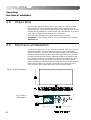
Fig 3.1 Unit dimensions.
Fig 3.2 Rack
dimensions.
6
Earthing Requirements
4.0
Earthing Requirements
WARNING! THIS APPLIANCE MUST BE EARTHED.
IMPORTANT: The wires in the mains lead are colour coded in accordance
with the following code.
Green and Yellow......Earth
Blue......Neutral
Brown......Live
As the colours of the wires in the mains lead may not correspond with
the markings identifying the terminals in your plug, proceed as
follows.
! The wire which is coloured Green and Yellow or Green must be connected
to the terminal which is marked with the letter ‘E’ or by the Earth signal
or which is coloured Green and Yellow or Green.
" The wire which is coloured Blue must be connected to the terminal
labelled ‘N’ or coloured Black or Blue.
# The wire which is coloured Brown must be connected to the terminal
labelled ‘L’ or coloured Red or Brown.
Those units supplied to the North American market will have an integral
moulded 3 pin connector which is provided to satisfy required local standards.
The mains voltage selector switch provides a simple external adjustment to
allow operation on all international AC power standards. The allowable ranges
for the supply voltage are:
90VAC up to 132VAC on the 115V position and
190VAC up to 264VAC on the 230V position.
Outside these ranges the unit will not work satisfactorily, if at all. Voltages in
excess of the maximum will probably cause damage. Voltages below the
minimum will cause the power supplies to drop out of regulation, degrading
the performance of the system.
7
Mains Power connection
5.0
Mains Power Connection
Voltage: The DPR-404 operates on either 120 or 240 volt supplies. Use the
voltage selector switch to choose the required voltage setting. (See Figure
8.1).
Frequency: Both 60Hz and 50Hz are acceptable.
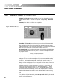
Fig 5.1 Mains fuse on
rear panel.
Grounding: The DPR-404 must always be connected to a 3-wire grounded
('earthed') AC outlet. The rack framework is assumed to be connected to the
same grounding circuit. The unit must NOT be operated unless the power
cables ground ('earth') wire is properly terminated - it is important for personal
safety, as well as for proper control over the system grounding.
AC Power Fusing: The incoming mains power is fused within the DPR-404 by
the fuse holder mounted on the rear panel. If it needs to be replaced it must
be properly rated as:
20mm T160mA for 240v AC
T250mA for 120v AC
It is most important for continued safety that this specification is adhered to,
and you will have found that spare fuses of this rating are supplied together
with your unit and manual. It is very unlikely that this fuse will fail during
normal use, and must be treated with some caution as to the cause, if it
should do so. One of the most likely reasons will be following the incorrect
setting of mains voltage switch on the rear panel. Another reason can be the
inadvertent connection of line to line rather than line to neutral phase
voltages when using a three phase power connection. In either case, the
internal transient suppressors (VDRs) can become damaged. If so, they’ll
consistently blow replacement fuses. You can be assured that they have
protected your unit from damage, that the cost of replacement is small and
that the VDR’s demise has saved the much higher cost of ‘blowing up’ an
entire unit. If blown, the VDRs will need removal to allow further use of your
unit.
If you believe this has happened, please refer to section 13.1 for the removal
and replacement procedure. They should be replaced as soon as possible to
ensure continued protection.
8
Power ON: This is indicated the green 'ON' LED located under the CH 'IN'
switches. If this LED is not lit when power is connected and the 'POWER'
switch is depressed, see section 16.
9
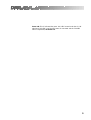
Getting to know the DPR-404
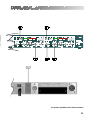
Fig 6.1 Front Panel
Fig 6.2 Rear Panel
10
All numbers in bubbles refer to Section numbers.
11
Audio connections
7.0
Audio connections
The DPR-404 audio inputs are RFI filtered and electronically balanced, with
the outputs electronically balanced and floating. They are designed to operate
at any signal level up to +20dBu and will drive into loads of 600 ohms or
greater. They will be ‘fuss free’, regardless of your installation’s complexity.
Note that pin 1 of the input XLR is not connected to ground.
7.1 Balanced
wiring
12
Whether your system is wired to a ‘pin 3 hot’ or a ‘pin 2 hot’ convention will
not matter as long as your wiring to both the input and output 3 pin XLR
connectors are the same . As is common with all other BSS equipment of this
type, we follow the convention of ‘screen goes forward with the signal’. Input
cable screening therefore needs to be derived from the signal source end as
pin 1 is ground lifted for the inputs. You should use high quality audio cable
with 2 cores + screen for low noise and reliability, and to sidestep potential
problems.
7.2 Unbalanced
wiring
If the equipment driving the DPR-404 has unbalanced outputs then you will
need to add a wire jumper such that the screen connection on Pin 1 of the
XLR is shorted to either Pin 2 or Pin 3, depending on the wiring convention of
the unbalanced equipment. If the equipment being connected to the DPR-404
outputs have only unbalanced inputs, then we recommend that you still use a
balanced (i.e. 2 core shielded) cable. The interconnecting cable should have
it’s screen grounded by pin 1 of the DPR-404 output, the pin 3 output should
be connected the unbalanced input 0v ground, and the pin 2 output should be
connected to the live input. There should be no connection between the cable
screen and the 0v/chassis ground connection of the unbalanced equipment.
Strict adherence to this will help to eliminate potential ground loop hums by
removing signal currents from the cable screen.
7.3 Ground loop
control
Adherence to the wiring conventions noted above within a fully balanced
signal system will yield the best possible results with none of the problems
normally associated with interconnected audio equipment. Wherever possible,
cable screens should not be connected to any signal pin, but rather left to
perform a cable shielding function only. Where it is not possible to control all
of the external cabling, it might become necessary to have the internal
electronic ground of your unit separated from the case safety ground. Provision
is made internally within the DPR-404 to separate these two grounds at a
convenient point, or to add a suitable impedance network as part of a house
system requirement. Under no circumstances should the safety ground wire be
removed from the mains AC power connector as an interim measure to
achieve similar results. Please refer to section 13.2, for information on this
procedure.
7.4 Linked
operation
For stereo program processing, channels 1 and 2 can be linked together by
selecting the LINK switch on channel 2. Channel 1 will assume the master
role, such that threshold, ratio, attack and release for channel two are equal to
and controlled by channel 1 with the side chain controlling signal being the
mono sum of both channels. This facility is also repeated for the second pair,
channels 3 and 4. HF de-essing is similarly treated, when using the LINK
mode. When processing stereo program, it is always important to maintain the
stereo imaging and prevent an audible shift in positioning. Channels 1 and 2
plus channels 3 and 4 can be selected to work as linked stereo pairs enabling
a stereo program to be successfully processed. Selecting the LINK switch on
channel 2 (or channel 4) re-connects the side chain circuitry such that
channel 1 (or channel 3) now derives the controls voltages for the summed
left/right program signal and applies it equally to both channels. Channel 1 (or
channel 3) is called the master, whilst channel 2 (or channel 4) the slave. The
master channels threshold, attack, release and ratio controls will now control
both master and slave channels simultaneously, with those on the slave
channel becoming inoperative.
13
Controls
8.0
Controls
8.1 IN
When depressed the processing is engaged and the green LED lights in
confirmation. When released, processing is disabled, the LED is off and the
incoming signal passes to the output unchanged and at unity gain.
8.2 Gain
Output level control used to restore signal after processing, providing ÿ 20dB
of adjustment range. Operation of this control has no affect on threshold
setting and should the output signal level approach +20dBv the adjacent red
LED will illuminate to indicate onset of clip.
8.3 Ratio
Used to set the scale factor for gain reduction, providing a range of 1:1 to
20:1. Low ratios have soft knee developing into hard limit at 20:1. When set
to ‘out’, no compression will occur even if signal level is exceeding threshold.
Sets the operating level at which compression will occur, adjustable from
+20dBv to -30dBv. Signal level in relation to threshold point is shown on the
gain reduction meter, such that when the TH LED is passed, compression will
commence.
14
8.4 Attack/Release
With the switches released, the function is automatically set and is program
related, such that it follows the signal requirements for general vocal and mix
program signals. (It closely follows the ‘auto’ mode on the DPR-402 unit).
When depressed, the function is again automatically set and program related
but is scaled to suit more transient program material such as percussion.
8.5 Below TH meter
Signal indicator showing the input signal level relative to the point at which
compression will commence. Anticlockwise rotation of the threshold control
brings the input signal into the compression window and determines the
threshold point. The half illuminated orange LED indicates the threshold point,
above which, compression occurs.
8.6 Gain reduction
meter
Shows the amount of gain reduction in dBs, being the difference between the
input and output signal levels. The scale increases from right to left such that
at all times the illuminated LEDs show the actual amount of gain reduction
used, whilst the non illuminated LEDs give an indication of the range of
reduction left from the maximum of 30dB.
15
8.7 De-ess
8.8 FREQ
8.9 Link
8.10 Link master
LED
16
Threshold control for the high frequency de-esser circuitry. It works
independently of the main compressor section and can be used simultaneously
with it. It uses a second subtractive element that works to reduce only those
high frequencies set by the FREQ control, leaving the other frequency content
of the program unprocessed. De-essing can be equally implemented on both a
full program mix or on an individual track, without fear of introducing audible
side effects.
Sets the operating frequency range for the HF de-esser. Control range is from
1kHz to 10kHz allowing precise alignment with sibilant frequencies without
affecting other parts of the program signal.
When depressed, channel one and channel two are linked together to form a
stereo pair. Channel one becomes the master and controls both the threshold,
attack, release, and ratio settings for both channels. The control side chain
signal is also mono summed from both channel inputs to ensure accurate
stereo processing. The de-essing function is linked in a similar manner. When
released, the channel is independent and operated from it’s own controls.
When illuminated, indicates that the channel is acting as the master for a
stereo pair, as selected by the link switch.
Rear panel controls
8.11 Main power
fuse
9.0
20mm, T160mA for 240v AC voltage setting and T250mA for 120v AC voltage
setting
Rear panel controls
9.1 Mains voltage
selector switch
9.2 Mains power
switch
9.3 Mains voltage
selector switch
Allows operation from 90v-130v or 190v-250v 50/60Hz AC mains voltage.
Turns the unit on/off.
Allows operation from 90V-130V or 190V-250V 50/60Hz AC mains voltage.
17
Rear panel controls
9.4 External side
chain insert
9.5 Electronically
balanced input
Offers a line level insertion point, on an RTS jack, into the control side chain.
Connections are: Ring:
Signal output from 470 source.
Tip:
Return input to 10k.
Sleeve:
0v ground.
Maximum input is +20dBu into 10kohms.
The pin connections are: Pin 1: Open circuit/no connection.
Pin 2: Hot (+).
Pin 3: Cold (-).
Note: Transformer balancing is available as an option.
9.6 Electronically
balanced and
floating output
Maximum output is +20dBu into 600ohms.
The pin connections are: Pin 1: Ground/Chassis.
Pin 2: Hot (+).
Pin 3: Cold (-).
Note: Transformer balancing is available as an option.
18
Compressors and Limiters
10.0
Compressors and Limiters
10.1 The need for
Gain Control
The human ear excels in its ability to detect an extremely wide range of
sound levels. These can range from the quietest whisper to the roar of a jet
aircraft. When we attempt to reproduce this large range (dynamic range) of
sounds with amplifiers, tape recorders or radio transmitters, we run into one of
the fundamental limitations of electronic or acoustic equipment. In some
cases, such as amplifiers, the dynamic range available is quite good.
However, equipment such as tape recorders and radio transmitters have a
restricted usable dynamic range.
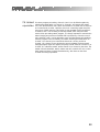
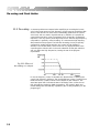
Fig 10.1 Dynamic
Range
What limits the available dynamic range of this equipment is its inherent
noise floor at the bottom end, and the maximum input signal resulting in an
acceptable amount of distortion at the upper end (See figure 1.2). The usable
dynamic range sits in between these two limits, and it is common practice to
operate a piece of equipment at a level that is somewhat below the upper
distortion point, leaving a margin of safety for the unexpected transient
loudness peaks present in program material. The safety margin is known as
headroom, and is generally in the range of 10 to 20dB. Lowering the standard
operating level to increase headroom helps distortion, but moves the average
program level nearer to the noise floor, thereby compromising the signal to
noise performance.
19
Compressors and Limiters
Fig 10.2 Operating level
and Headroom
It therefore becomes apparent that to get the most out of an audio system, the
standard operating level must be kept as high as possible without risking
distortion.
One solution to this problem is for the operator of the equipment to be
continuously monitoring the program, and manually adjusting the gain to suit
the moment. When the program is quiet, the gain can be increased, and when
the program is loud the gain can be reduced. However, in most types of
program there are instantaneous short duration level peaks or transients, which
would be difficult to anticipate and impossible to respond to in the required
time. Even a sound engineer with the quickest reflexes could not bring the
gain knob or fader down quickly enough.
The need therefore arises for a fast acting automatic gain controlling device
which will track the program material constantly, and which will always
adjust the gain to maximise the signal to noise performance without incurring
distortion. This device is called a compressor or limiter, and is one part of the
DPR-404.
10.2 Compressors
and Limiters
Compressors and limiters have closely related effects, and in general a limiter
will reduce gain very strongly once a certain level has been reached, whereas
a compressor will act gently, but over a much wider range of volume levels.
A limiter will continuously monitor program levels, but only commence to
reduce gain once the level has exceeded a preset amount. This point is called
the threshold level. Any program level in excess of the threshold will
immediately be reduced to this threshold level.
A compressor will also continuously monitor the program and has a threshold
level. However, program signals in excess of this threshold will be
progressively reduced by an amount (ratio) depending on the degree to which
it initially exceeds the threshold. Generally, threshold levels for compressors
are set below the normal operating level to allow them to reduce the dynamic
range of the signal gradually, so that they are acceptable to following
equipment. For limiters, the threshold point will be set above the operating
level in order to provide a maximum level for signals to following equipment.
20
In the DPR-404, gain reduction is achieved by using a proprietary subtractive
circuit which minimises signal degradation and has a maximum attenuating
range of 30dB. The THRESHOLD control is used to position the input program
signal into the window of operating range for the circuit. Rotating the control
anticlockwise from the ‘out’ position will bring the signal onto the BELOW TH
meter. Gain reduction will commence once the dimly lit TH LED is
exceeded, and the actual amount of reduction in gain shows on the GAIN
REDUCTION METER, calibrated in dBs. The RATIO control is used to scale
the reduction effect once threshold is exceeded, and the scale numbers relate
to the amount of program signal, in excess of threshold, that will cause a 1dB
increase in output level. For general compression a ratio of between 2:1 and
4:1 is an optimum starting point. For limiting a ratio of between 10:1 and 20:1
is to be used.
The response of the DPR-404 to signals above threshold is further defined by
the ATTACK and RELEASE controls. These control how quickly gain reduction
occurs and, following signal level dropping below threshold, how slowly the
gain reduction is removed and unity gain restored. It is important that these
controls are set to suit the particular program envelope and the DPR-404 is
provided with two automatic ranges that are designed to carefully optimise
these times to the signal. With the switches in their released position, the
times are set to work within a range typical of vocals, mix program material
and other non transient sources. When compressing very fast percussive
sounds it is recommended that the fast auto modes are selected by depressing
the switches. Any combination can be used and it is best that the optimum
setting be found by listening for the desired effect. In general too fast an
attack will cause high frequency distortions and clicking sounds, whereas too
fast a release will give level pumping effects and low frequency distortions.
Because compression is a gain reducing effect, the output signal is often at a
lower level than normal.
The GAIN control, scaled in dBs, is provided to restore the output signal level.
It is positioned after the reduction process and therefore has no effect on the
threshold setting. The associated red LED will give an indication that output
level is approaching the maximum operating level for the channel. Should
you wish to bypass the compress ion effect, releasing the IN switch will
restore the output signal to that of the input. The green LED illuminates to
show when the channel is active. The LED metering remains active even in
the bypassed mode, so that some initial setting up can be done before
selecting the IN.
21
The effect of Compression
11.0
The effect of Compression on sound
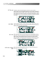
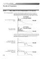
11.1 Compression
Consider an input signal which is applied to two units, one having its
threshold point set 10dB higher than the other. Since the compressor only
affects signals that exceed the threshold level, the signal with the lower
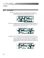
threshold applied will be more affected than the other. Referring to figures
Fig 11.1a High threshold
level
Fig 11.1b Lower
threshold level
2.2a & b, assuming that all other controls on both channels are set identically
with gains equalised, it is immediately apparent that the signal processed with
the higher ratio is said to have been limited, whereas the signal with the
lower ratio is said to have been compressed.
Fig 11.2a Effect of
compression with high
threshold
Fig 11.2b Effect of
compression with lower
threshold
22
Comparing the input and output waveforms for the compressed mode, the
loudest portions of the signal have been effectively decreased in level, and if
the gain control is adjusted to compensate for this, the quieter portions will be
increased. The net effect, therefore, is for both ends of the dynamic spectrum
to be pushed (or squeezed) towards each other. This squeezing effect of
compression is important to remember, and provides a major difference
between compression and limiting. I.e. Limiters do not make-up the gain
reduction.
The range provided by the DPR-404 on its ratio and release controls is
sufficient to allow its use either as a compressor or limiter. For limiter
applications, the release fast switch should generally be out.
11.2 Attack,
Release and Ratio
Attack is the amount of time that elapses before the compressor begins to
attenuate the output level after the threshold point has been exceeded. For
sounds such as a snare drum or hand clap, fast attack is desirable so that the
compressor responds in time to control the peaks.
Release is the amount of time taken for the compressor to return to normal
gain after the input signal has fallen BELOW the threshold point.
Ratio determines the ratio of change on output level to changes in input level
for all signals that exceed the threshold. Returning to section 1.1 where the
idea of manual controlling the level of the program was discussed, the
operator would reach over and turn down the volume if signal levels were
approaching distortion. At this point he now has an option: Either reduce the
level so that there is nothing exceeding his desired maximum level, or reduce
the level by a small amount so that his output is slightly greater than that of
his preferred maximum but not as loud as it would have been if no action had
been taken. This action is known as the ratio. A ratio of 1:1 indicates that the
output will linearly track the input level of the threshold. i.e. For every 1dB of
input over the threshold point, there will be 1dB of output. A ratio of 2:1
indicates that for every 2dB of input level above the threshold, there will be a
corresponding increase of 1dB in the output level. A ratio of 10:1 indicates
that for every increase of 10dB of input level, there will be a corresponding
increase of 1dB in the output level, and so on. A ratio of infinity:1 indicates
that no matter how loud the input signal goes above the threshold, the output
will remain constant at the threshold point. It is worth noting that a hard or
infinite ratio limit has applications in some specialised situations, but in
general it is neither appropriate nor necessary, and is likely to cause noticable
side effects in the sound.
23
De-essing and Peak Limiter
11.3 De-essing
A common problem encountered when amplifying or recording the human
voice is the large amount of high frequency energy heard as the sibilant (Sss)
sound. These sounds can reach levels considerably greater than the normal
voice level, and can result in signal break-up or distortion. It is possible to
control these sounds by using a compressor which is specially configured to
respond to, and only reduce, these high frequencies. Selective high frequency
compression is generally called de-essing, as it removes the high frequency
Sss content from the program. The DPR-404 de-essing circuitry is specially
configured to enable precise selection and control of high frequency
sibilance. The variable FREQ control tunes not only high pass filters in the
controlling side chain but also in the main subtracter so that gain reduction
will only affect the high frequencies, leaving the rest of the program
unprocessed.
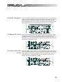
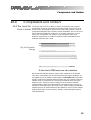
Fig 12.1 Effect of
de-essing on output
In use, the frequency control is adjusted such that the filter is capturing the
correct high frequency sibilance, and the DE-ESS level control, working like a
threshold control, is used to set the correct degree of gain reduction. The
associated green LED indicates the start of de-essing action, whilst the red
LED indicates the maximum 10dB compression. The dynamic attack and
release settings are automatically adjusted by the circuitry depending on the
program type.
24
Specifications
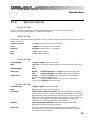
12.0
Specifications
Input section
12k ohm electronically balanced, +20dBu (+20dBv) maximum input level via a 3 pin male XLR
cable plug. Common Mode rejection: > -50dB, 20Hz to 20kHz
Input section
Electronically balanced and floating, capable of driving +20dBu (+20dBv) into 600 ohms or greater via an XLR
female cable plug.
Frequency response:
+/- 0.5dB, 20Hz to 20kHz (Low pass at 29kHz)
Noise:
<-86dBu, all controls set flat, 22Hz - 22kHz
Distortion:
Unity gain +10dBv output, no compression
THD:
< 0.05% (20Hz-20kHz)
IMD:
< 0.02% (SMPTE method)
Input section
Threshold Range:
+20dBv to -30dBv continuously variable
Ratio:
1:1 to 20:1 continuously variable (Soft knee for low values with hard limit at
20:1)
Maximum Range:
30dB
Attack Time:
Normal:
Fast:
Release Time:
Normal:
Typically 10 mSecs for 63% recovery from a 10dB 4mSecs
overdrive, and 1 Sec for 10dB 40 mSec
Fast:
Typically 2 mSecs for 63% recovery from a 10dB 4mSecs
overdrive, and 300 mSec for 10dB 40 mSec
Program dependent, with 200uS for fast transient overdrives.
Program dependent, with 20uS for fast transient overdrives.
Output section
Threshold Range:
+20dBv to -30dBv continuously variable
Ratio:
20:1 at and above twice the set frequency
Freq Range:
1kHz to 10kHz continuously variable. Attack times are those as measured to
achieve 63% of final gain reduction with a step signal of 8dB above threshold.
Release times are those as measured to achieve 63% recovery of open gain or
removal of a signal 8dB above threshold. The frequency at which 3dB of gain
reduction occurs for 10dB of signal drive above threshold. 10dB of gain
reduction will occur at and above twice this frequency
Metering:
13 way dB calibrated LED meter display showing signal level below
threshold, threshold point and gain reduction
Stereo Link:
Front panel switch selects Channels 1/2 and 3/4 to become stereo pairs.
Channel 1 and channel 3 assume master function for their pair. Side chain
control signal is mono summed
25
Specifications
Side chain insert:
Rear panel RTS jack accesses side chain for inserting other equipment at line
level. Connections are: Ring:
Signal output from 470 ohms source
Tip:
Return input into 10kohms
Sleeve:
0v ground
Power:
AC 50/60Hz 120v/240v switched externally giving operation range of 90-132v
and 180-264v. Anchored 2m power cord
Size:
482 x 44 x 282mm
19” x 1U x 11.10"
Weight:
4.1kg gross shipping
Options
Transformer balancing for input and output.
26
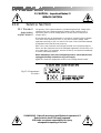
!!! CAUTION - Important Notes !!!
SERVICE SECTION
13.0
Service Section
13.1 Transient
suppressor
replacement
The primary of the input transformer is protected against high voltage spike
interference by two voltage dependent resistors (VDR). These provide a
momentary short circuit to voltage peaks in excess of the normal power
voltage rating.
Should the DPR 404 be inadvertently connected to 3-phase line/line voltages
or to 240V when selected for 120V, or any other incorrect voltage, these
suppressors are likely to fail in a short circuit mode. This will be demonstrated
by repeated mains fuse failure at power up.
Even in this case of extreme over-voltage, the DPR 504 is protected against
failure, and the simple removal of the damaged suppressors will allow the unit
to be used again. It is important, however, that they are replaced immediately
to ensure continued protection.
Before attempting to remove the damaged suppressors, ensure that the unit is
unplugged and totally isolated from any power supply.
Figure 13.1 shows the suppressors location on the voltage selector board.
Fig 13.1 Suppressor
location
!!! WARNING - Refer all servicing to qualified service personnel !!!
Risk of electric shock if the unit is opened.
BSS Audio accepts no responsibility for injury
subsequent to opening of the unit.
27
!!! CAUTION - Important Notes !!!
SERVICE SECTION
13.2 Separating
signal and chassis
ground
In some installations, it might be necessary to separate the electronic signal
0V ground from the chassis ground to avoid earth loops.
Since both the inputs and outputs of the DPR 504 are balanced, correct
connector wiring should be alleviate this problem. Prior to continuing with this
procedure, it is recommended that you recheck all audio wiring for
correctness.
Should it be necessary, then the simple removal of an internal wire link
accomplishes this task. Refer to figure 13.2 for the location of this wire link.
To remove the wire link, you will need to remove the top cover of the unit,
and then remove the top PCB, and 4 LED PCBs. The chassis link point will
then be accessible, located between C512 and C502 labels (white silk screen)
on the main PCB.
On no occasion should the incoming safety ground wire be disconnected from
the line cord or from the internal chassis connection as an alternative to this
procedure.
Fig 13.2 Chassis link
location
!!! WARNING - Refer all servicing to qualified service personnel !!!
Risk of electric shock if the unit is opened.
BSS Audio accepts no responsibility for injury
subsequent to opening of the unit.
28
Warranty Information
14.0
Warranty Information
When sold to an end user by BSS Audio or a BSS Audio Authorised Reseller,
this unit is warranted by the seller to the purchaser against defects in
workmanship and the materials used in its manufacture for a period of one
year from the date of sale.
Faults arising from misuse, unauthorised modifications or accidents are not
covered under this warranty. No other warranty is expressed or implied.
If the unit is faulty it should be sent to the seller of the equipment, in its
original packaging with shipping prepaid. The unit will be returned to you
when the repair has been completed. If the unit was purchased witin the
European Union, you may, as an alternative, return the unit to any other BSS
distributor in the European Union.
You should include a statement listing the faults found. The unit’s serial
number must be quoted in all correspondence relating to a claim.
IMPORTANT
We recommend that you record your purchase information here for future
reference.
Dealer Name:
Dealer Address:
Post/Zip Code:
Dealer Phone No.:
Dealer Contact Name:
Invoice/Receipt No.:
Date of Purchase:
Unit Serial Number:
In keeping with our policy of continued improvement, BSS Audio reserves the
right to alter specifications without prior notice.
The DPR-404 was designed and developed by BSS Audio, Hertfordshire,
England.
Phone (+44) (0)1707 660667. Fax (+44) (0)1707 660755.
World Wide Web address: http://www.bss.co.uk
29
Index
Index
A
Attack Time
21
B
Below Threshold. See Compression meters; Compression meters:
Below Threshold
C
Chassis ground
separating from signal
Compression
26
20
D
Dynamic Range
17
E
Earthing
7
F
Front Panel
Fuses. See Mains Connection
10
G
Gain Reduction. See Compression meters: Gain Reduction
Getting to know the DPR-402
10
Grounding. See Grounding
H
Headroom
18
I
Installation
6
M
Mains Connection
8
Meter Input. See Compression meters: Meter Input
O
Output Level. See Compression meters: Input Level
P
Power ON. See Mains Connection
R
Rack space.. See Installation
Rear Panel
30
10
Index
Release time
21
S
Specifications
23
T
Threshold
Transient suppressor
replacement
14
25
U
Unpacking
6
W
Warranty Info.
27
31
User Notes
32
User Notes
33