1
BP-002 User's Manual
Important Safety Instructions
Read all of these instructions carefully and thoroughly and save them for later reference. The
unauthorized operation would lead to malfunction or accident. Manufacturers have no
responsibilities for the problems which are led by misoperations.
1.
Follow all warnings and instructions in the manual as well as marked on the product.
2.
Don’t touch the thermal print head with your hand at any moment to avoid the thermal head damaged.
3.
Be careful the manual cutter when you are installing the paper.
4.
Unplug this product from the power outlet before cleaning. Do not use liquid or aerosol cleaners. Use a
damp cloth for cleaning.
5.
Please don’t use the printer near water.
6.
Do not place this product on an unstable cart, stand or table. The product may fall, causing serious
damage to you or the product.
7.
Slots and opening on the cabinet and the back or bottom are provided for ventilation. To ensure reliable
operation of the product and to prote ct it from overheating, do not block or cover these openings. The
openings should never be blocked by placing the product on a bed, sofa, rug or other similar surface.
This product should not be placed in a built-in installation unless proper ventilation is provided.
8.
This product should neve r be placed near or o ver a radiator or heat origin, and should a void of direct
sunshine.
9.
Do not locate this product w here the cord will be walked on. When the cord or the plug is mangled,
please stop using and get a new one replaced. Make sure the old one is far away from the printer, so it
can avoid someone who does not know the inside story getting damage.
10. Be sure to use the specified power source. Connection to an improper power source may cause fire or
shock.
11. Do not use in locations subject to high humidity or dust levels. Excessive humidity and dust may cause
equipment damage or fire.
12. Never push ob jects of any kind into this product though cabinet slots as they may tou ch dangerous
voltage dots or short out parts.
13. Don’t remove the printe r’s out-cover and rep air the printer. When n eeded, call or t ake it to the
professional.
14. If water or other liquid spi lls into this equipment, unplug the power cord immediately, and then contact
your dealer or a service center for advice.
15. To ensure safety, please unplug this product prior to leaving it unused for an extended period. The wall
outlet you plan to connect to should be nearby and unobstructed.
16. Unplug this prod uct from the wall out let and refe r servicing to qualified service person nel under the
following conditions:
a)
When the power cord or plug is damaged or frayed.
b)
If liquid has been spilt into the product.
c)
If the product has been exposed to rain or water.
d)
If the product does not operate normally when the operating instructions are followed.
e)
If the product has been dropped or the cabinet has been damaged.
f)
If the product exhibits a distinct change in performance, it indicates a need for service.
Warning: In order to ensure the printer life, strictly prohibit printing full line full black
exceeding 2 CM.
-i-
BP-002 User's Manual
Notice: The contents of this manual are subject to change without notice.
*All the parts of the printer can be recycled. When it is abandoned, we can call it back freely.
Please contact us when you abandon it.
- ii -
BP-002 User's Manual
Table of Contents
Important Safety Instructions .....................................................................................................................i
Chapter 1 Overview ....................................................................................................................................1
1.1 Features ..............................................................................................................................................1
1.2 Product Model Description ..................................................................................................................1
1.3 Main Parts of the Printer......................................................................................................................1
Chapter 2 Installing the Printer..................................................................................................................3
2.1 Unpacking & Checking ........................................................................................................................3
2.2 Removing the Protective Materials......................................................................................................3
2.3 Connecting to Your Computer or Other Equipment .............................................................................3
2.3.1 Connecting the Cash Drawer Cable .............................................................................................3
2.3.2 Connecting the Parallel Interface Cable .......................................................................................4
2.3.3 Connecting the USB Interface Cable ............................................................................................4
2.3.4 Connecting the Serial Interface Cable ..........................................................................................5
2.3.5 Connecting the Ethernet Interface Cable......................................................................................5
2.4 Connecting the Power Cord ................................................................................................................6
2.5 Installing the Driver .............................................................................................................................7
2.6 Installing Bluetooth Interface Driver ....................................................................................................9
2.7 Ethernet Settings............................................................................................................................... 11
2.7.1 Connecting Printer...................................................................................................................... 12
2.7.2 Setting IP Address ...................................................................................................................... 12
2.8 Wi-Fi Setting...................................................................................................................................... 14
2.8.1 Connect to the Printer, Run the WiFiConfig Software .................................................................15
2.8.2 Set Wi-Fi Parameters ................................................................................................................. 16
2.8.3 Checking Wi-Fi Parameters........................................................................................................ 17
2.8.4 Recover the Default Setting........................................................................................................ 18
2.9 Installing Printer Network Driver........................................................................................................ 18
Chapter 3 Control Panel........................................................................................................................... 25
3.1 Control Panel .................................................................................................................................... 25
3.1.1 Indicator light .............................................................................................................................. 25
3.1.2 Key ............................................................................................................................................. 25
3.2 Self-Printing....................................................................................................................................... 25
3.3 Hex Dump Printing ............................................................................................................................ 25
3.4 Restoring Factory Printer Settings .................................................................................................... 25
3.5 Setting Slip Stitch (UPDATE and BOOT)........................................................................................... 26
3.6 Online-aptitude Parameter Settings .................................................................................................. 26
Chapter 4 Installing Paper........................................................................................................................ 28
4.1 Paper Installation Steps..................................................................................................................... 28
Chapter 5 Specification ............................................................................................................................ 30
5.1 General Specificaion ......................................................................................................................... 30
5.2 Interface Specifications ..................................................................................................................... 31
- iii -
BP-002 User's Manual
5.2.1 Cash Drawer Interface................................................................................................................ 31
5.2.2 Parallel Interface......................................................................................................................... 32
5.2.3 USB Interface ............................................................................................................................. 33
5.2.4 Serial Interface ........................................................................................................................... 33
5.2.5 Ethernet Interface ....................................................................................................................... 34
5.2.6 Power Supply Inlet...................................................................................................................... 35
Chapter 6 Troubleshooting and Maintenance ........................................................................................ 36
6.1 Maintenance...................................................................................................................................... 36
6.2 Error Message on the Control Panel ................................................................................................. 36
Chapter 7 Control Commands ................................................................................................................. 37
7.1 General ............................................................................................................................................. 37
7.2 Explanation of Terms......................................................................................................................... 37
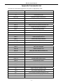
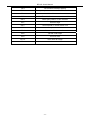
Appendix Commands List ....................................................................................................................... 48
- iv -
BP-002 User's Manual
Chapter 1 Overview
1.1 Features
BP-002 is a low-cost and high-reliability thermal printer facing low-income market. It can be widely
used in the fields of supermarket, POS, catering, electronic instrument and so on.
1.2 Product Model Description
According to different data ports (interfaces), BP-002 series is classified into several different models:
BP-002BP, BP-002BU, BP-002BR, BP-002BN, BP-002BT, BP-002BF, BP-002WP, BP-002WU,
BP-002WR, BP-002WN, BP-002WT, BP-002WF
Configuration of each model:
The products of this series are configured with a cash drawer interface. You can choose one of the
following models when purchasing this printer.
Model
BP-002BP
BP-002BU
BP-002BR
BP-002BN
BP-002BT
BP-002BF
BP-002WP
BP-002WU
BP-002WR
BP-002WN
BP-002WT
BP-002WF
Interface
Parallel interface
USB interface + Serial interface
USB interface + Serial interface
USB interface + Ethernet interface
USB interface + Bluetooth interface
USB interface + Wi-Fi interface
Parallel interface
USB interface + Serial interface
USB interface + Serial interface
USB interface + Ethernet interface
USB interface + Bluetooth interface
USB interface + Wi-Fi interface
Cable
Parallel interface cable
USB interface cable
Serial interface cable
Ethernet interface cable
USB interface cable
USB interface cable
Parallel interface cable
USB interface cable
Serial interface cable
Ethernet interface cable
USB interface cable
USB interface cable
Color
Black
Black
Black
Black
Black
Black
White
White
White
White
White
White
Note: Please contact the local dealer to change the interface with added expense if needed.
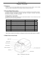
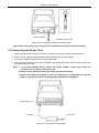
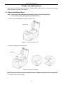
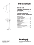
1.3 Main Parts of the Printer
Upper cover
Manual cutter
Power indicator
Error indicator
Paper out indicator
Cover-opening button
FEED key
Power switch
Figure 1-1 Main parts of the printer
-1-
BP-002 User's Manual
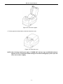
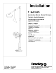
Cash drawer interface
Data interface
Power supply inlet
Figure 1-2 Back interfaces of the printer
Note: According to the specific interface standards
-2-
BP-002 User's Manual
Chapter 2 Installing the Printer
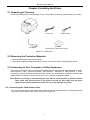
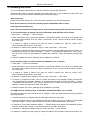
2.1 Unpacking & Checking
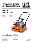
Check the following items in the package, if any of these items is missing, please contact your dealer.
Printer
Power Cord
AC Adapter
Interface Cable
Driver CD
(Including User's Manual and Driver)
Figure 2-1 Packing List
2.2 Removing the Protective Materials
1. Open the packing box, take out the printer.
2. Save all the original packing materials so that they can be used when transporting the printer.
2.3 Connecting to Your Computer or Other Equipment
The printer is configured with a cash drawer interface and one data interface (parallel interface, USB +
serial interface, USB + Ethernet interface, USB interface + Bluetooth or USB interface + Wi-Fi).
(According to specific interface standards) Please contact your local dealer to change the interface with
added expense if needed. Connect the printer to your computer as described below.
Note: Before connecting or disconnecting the cash drawer, serial interface or parallel interface
cable, make sure that the power of the printer is turned off. Also make sure the power
cable is disconnected with the AC outlet. Or else it may damage the printer.
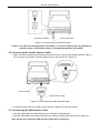
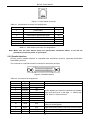
2.3.1 Connecting the Cash Drawer Cable
Turn off the printer and plug the cash drawer cable into the cash drawer interface of the printer and the
other end is connected to cash drawer, as shown in Figure 2-2.
-3-
BP-002 User's Manual
Cash Drawer Interface
Cash Drawer Cable
Figure 2-2 Connecting the cash drawer cable
Caution: You must use the appropriate cash drawer, or else our company will not guarantee to
keep the printer in good repair when it is damaged by improper cash drawer.
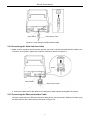
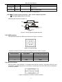
2.3.2 Connecting the Parallel Interface Cable
1. Make sure the computer and the printer are both turned off, connect the parallel interface cable to
the connector of the printer, and then fasten the wire clips as shown in Figure 2-3.
Wire Clips
Parallel Interface
Parallel Interface Cable
Figure 2-3 Connecting the parallel interface cable
2. Connect the other end of the cable to the computer. Tighten the connector screws.
2.3.3 Connecting the USB Interface Cable
1. Plug the USB cable A end (flat shape) into the computer's USB interface.
2. Plug the USB cable B end (square shape) into the printer's USB interface as shown in Figure 2-4.
Note: Please don’t impact the USB interface cable after connecting it.
-4-
BP-002 User's Manual
USB Interface Cable
USB Interface
Figure 2-4 Connecting the USB interface cable
2.3.4 Connecting the Serial Interface Cable
1. Make sure the computer and the printer are both turned off, connect the serial interface cable to the
connector of the printer. Tighten the connector screws as shown in Figure 2-5.
Screws
Serial Interface
Serial Interface Cable
Figure 2-5 Connecting the serial interface cable
2. Connect the other end of the cable to the computer’s serial interface and tighten the screws.
2.3.5 Connecting the Ethernet Interface Cable
Plug the crystal end of the Ethernet interface cable (RJ-45) into the printer's Ethernet interface, plug
the other end into the LAN’s entrance as shown in Figure 2-6.
-5-
BP-002 User's Manual
Ethernet Interface
Ethernet Interface Cable
Figure 2-6 Connecting the Ethernet interface cable
Note: Please refer to the user’s manual for the detailed instructions of internet settings.
2.4 Connecting the Power Cord
1. Make sure the printer’s power is turned off. (O mark on the power switch is pressed down)
2. Make sure the voltage of the electrical outlet matches that of the AC adapter.
3. Plug the AC adapter to the printer’s power supply inlet.
4. Plug one end of power cord into the AC adapter, and then plug the other end of power cord into the
grounded electrical outlet.
Note: 1. If the rated voltage doesn’t match the outlet voltage, contact your dealer for
assistance. Do not plug in the power cord.
2. Please use the electrical outlet connecting the ground properly.
3. Please use original AC adapter, or else, our company will not guarantee to keep the
printer in good repair when it is damaged by unauthorized AC adapter.
Power Supply Inlet
Power Cord
AC Adapter
Figure 2-7 Connecting the AC adapter
-6-
BP-002 User's Manual
2.5 Installing the Driver
You should setup the printer driver in Windows before using the BP-002 printer.
Please use the cable to connect computer with printer, then turn on the computer and the printer, put
the driver CD into the CD-ROM. Install driver by the following ways:
Auto-install way
Double click the file “Setup.exe” in the driver disc, install driver by the following direct.
Note: Auto-install way needs the operating system of Windows 2000 or above.
Hand operated installing way
Note: The hand-operated installing ways of serial interface and parallel interface are the same.
1) The installing steps of parallel interface for Windows 2000/XP/Vista are as follows:
1 Click “Start” → “Settings” → “Select Printers”.
2. Click “Add Printer”, then it pops up a window of “Add Printer Wizard”, click “Next”, then please read
the select guide carefully, such as, select “Local printer” in the “Local or Network Printer” window,
then click “next”.
3. A window of “Select a Printer Port” pops up, select a usable port. Such as, select “LPT1:
(Recommended Printer Port)”, click “Next”.
4. A window of “Install Printer Software" pops up, click “Have Disk...”, click “Next”.
5. A window of “Install From Disk” pops up. Please according to the operating system environment, you
should select the path as follow: CD-ROM → “Driver” → “WIN2000 (XP-Vista-Win7)”, click “Open”,
then click “OK” to return to the window of “Install Printer Software”, select the respective model, click
“Next”.
6. Follow the guide click “Next” gradually till the installation is finished.
2) The installing steps of parallel interface for Windows 7 are as follows:
1. Click “Start” → “Device and Printers”.
2. Click “Add Printer”, then it pops up a window of “Add Printer Wizard”, click “Next”, then please read
the select guide carefully, such as, select “Local printer” in the “Local or Network Printer” window,
then click “next”.
3. A window of “Select a Printer Port” pops up, select a usable port. Such as, select “LPT1:
(Recommended Printer Port)”, click “Next”.
4. A window of “Install Printer Software” pops up, click “Have Disk...”, click “Next”.
5. A window of “Install From Disk” pops up. Please according to the operating system environment,
such as Windows XP operating system, you should select the path as follow: CD-ROM → “Driver”
→“WIN2000 (XP-Vista-Win7)”, click “Open”, then click “OK” to return to the window of “Install Printer
Software”, select the respective model, click “Next”.
6. Follow the guide click “Next” gradually till the installation is finished.
The USB interface installing steps for Windows 2000/XP/Vista/Win7 are as follows:
The following steps are used Windows XP as example. There are slight differences among different
operating systems.
1. Connect the printer to computer with an USB cable and turn on the printer.
2. After the computer find out new hardware and finish searching, pop up a window of “Found New
Hardware Wizard”, choose “Install from a list or specific location (Advanced)”, click “Next”.
3. A window of “Found New Hardware Wizard” — “Please choose your search and installation options”
pops up, choose “Don't search, I will choose the driver to install”, click “Next”.
4. A window of “Add Printer Wizard” pops up, click “Have Disk...”, click “Browse”.
5. A window of “Install From Disk” pops up. Please according to the operating system environment, you
-7-
BP-002 User's Manual
should select the path as follow: CD-ROM → “Driver” → “WIN2000 (XP-Vista-Win7)”, click “Open”,
then click “OK” to return to the window of “Add Printer Wizard", select the respective model, click
“Next”.
6. Follow the guide click “Next” gradually till the installation is finished.
The installing steps for Windows 98 are as follows:
(1) The installing steps with a parallel cable or a serial cable:
1. Click “Start” → “Settings” → “Printers”.
2. Click “Add Printer”, then a window of “Add Printer Wizard” pops up, click “Next”, then please read
the select guide carefully, such as, select “Local printer” in the “Local or Network Printer” window,
then click “Next”.
3. A window of “Click the manufacturer and model of your printer” pops up, click “Have Disk...”,
please click “Browse”, select the path as follow: CD-ROM → “Driver” → “WIN98 (WINME)”, then
click “OK”.
4. A window of “Install From Disk” pops up, click "OK, return to a window of “Add Printer”, then click
"Next".
5. A window of “Printer port” pops up, select “Available ports”, such as, select “LPT1: Printer Port”,
click “Next”, and then show the printer’s name. If the system is not installed by other printer driver
process, the printer is treated as default printer by the application process of Window98
environment, click “Next”. Otherwise according to prompt, choose the printer is default: “Yes”, click
“Next”, choose “Yes-(recommended)”, click “Finish”. A window of “Printer test page completed”
pops up, click “Yes”.
6. The printer driver process is installed successfully.
(2) The installing steps with an USB cable:
Note: 1. As the system of Windows 98/ME doesn’t have integrated USB driver control, please
install USB driver before using USB interface printing. Then install USB printer
driver.
2. If it has installed the USB driver, please install the USB printer driver directly as the
following steps.
USB driver installing steps:
1. Connect an USB cable and turn on the printer.
2. After the computer find out new hardware and finish searching, a window of “Add New Hardware
Wizard” pops up, click “Next”.
3. A window of “Add New Hardware Wizard” — “Windows operation” pops up, choose “Search the
best driver for the device (recommended)”, click “Next”.
4. A window of “Search for new drivers” pops up, check “Specify a location”, click “Browse”, select
the path as follows: CD → ROM → “Driver”-“[WIN98 (WINME) \ USBdriver]”, then click “OK”.
5. Return to a window of “Search for new drivers”, click “Next”; a window of “Windows driver file
search for the device” pops up, click “Next”.
6. After the system finishing installing the file automatically, a window of “USB Print Supported” pops
up, click "Finish".
7. The printer USB driver process is installed successfully.
USB printer driver installing steps:
1. Click “Start” → “Settings” → “Printers”.
2. Click “Add Printer”, then a window of “Add Printer Wizard” pops up, click “Next”.
3. A window of “Click the manufacturer and model of your printer” pops up, click “Have Disk...”,
please click “Browse”, select the path as follow: CD-ROM → “Driver” → “WIN98 (WINME)”, and
then click “OK”.
-8-
BP-002 User's Manual
4. A window of “Install From Disk” pops up, click “OK”, return to a window of “Add Printer”, then click
"Next".
5. A window of “Printer port” pops up, select “Available ports”, select “JMUSB”, click "Next", and then
show the printer’s name. If the system is not installed by other printer driver process, the printer is
treated as default printer by the application process of Window98 environment, click “Next”.
Otherwise according to prompt, choose the printer is default: "Yes", click "Next" choose
“Yes-(recommended)”, click “Finish”. A window of “Printer test page completed” pops up, click
“Yes”.
6. The printer driver process is installed successfully.
2.6 Installing Bluetooth Interface Driver
Note: Select to install this driver according to the chosen model.
1. Choose the appropriate Bluetooth adapter, the operation system is Window XP or above which with
Bluetooth adapter driver.
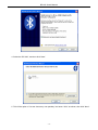
2. Turn on the printer, search Bluetooth device in Window XP system, and click “Add”.
3. Tick off the option of “My device is set up and ready to be found.” Click “Next” to continue.
-9-
BP-002 User's Manual
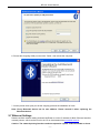
4. Select the “BP-002”, and then click “Next”.
5. Tick off the option of “Let me choose my own passkey” and enter “1234” as shown, then click “Next”.
- 10 -
BP-002 User's Manual
6. Record the Outgoing COM port and click “Finish”, then reboot the computer.
7. Set the printer driver print port as the outgoing port and the installation is finish.
Note: Every Bluetooth device has its own address. Please reinstall it when replacing the
Bluetooth device.
2.7 Ethernet Settings
Please use Birch network setting software NetFinder to set the IP address for Birch Ethernet interface
network printers, which can be found in the CD or downloaded from www.birch.com.tw.
Caution: The network printing function needs the operation system of Windows2000 or above.
- 11 -
BP-002 User's Manual
2.7.1 Connecting Printer
Power on the printer, connect with the Ethernet cable which has been connected to LAN, and look into
the information of Ethernet LED indicator to ensure the printer has entered into the normal connection.
Yellow LED
Green LED
Description
ON
Blink
Connecting to network
OFF
OFF
Not connecting to network
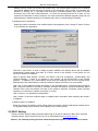
2.7.2 Setting IP Address
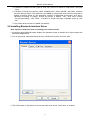
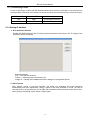
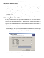
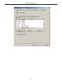
1. Run NetFinder Software
Double click NetFinder.exe in the PC which connects the printer in the same LAN. The figure of the
software is shown as follows:
Button description:
Exit — Exit from the software
Search — Search printers in the same LAN
Assign IP — Modify the IP address and other settings for the specified printer.
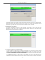
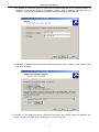
2. Search printer
Click “Search” button in the main interface, the dialog box appearing will begin searching
automatically and show appearance, listing a printer in the main interface if found. The time is
counting down in the progress bar (10s in total) and the search will finish as soon as the time is over.
When going on searching, press “search” button again.
- 12 -
BP-002 User's Manual
If the printer still can not be found out when the network connection is correct in the same network,
please check whether the network fire wall on the PC opens or not. If there is fire wall, please close it
temporarily, open again after finishing searching and setting a printer completely.
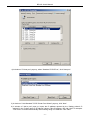
3. Setting printer’s IP address
The printer’s information is listed in the main interface, the left side of which is the model and
description and the right are the IP address and MAC address. What’s more, the assign mode
(dynamic/static) is noted behind the IP address.
1) Correlative description for IP address settings
In order to search and set printer’s IP address conveniently for the first time, the factory default
setting is DHCP mode which assigns IP address dynamically. If there is no DHCP server in the
connected LAN and printer is set to DHCP mode as well, then it will use the internal pre-set address
(IP: 10.0.0.1, Subnet Mask: 255.255.255.0) automatically.
It is suggested that printer’s IP set to static in actual usage, which can cut down the time when
initializing the Ethernet interface as the printer is turned on and prevent IP conflicts (The dynamic
- 13 -
BP-002 User's Manual
address used in printer may conflict with another one). The network segment part of the IP address
and Subnet Mask must be the same as those of PC connecting with a printer. For example, the
address of working PC is 192.168.0.1/255.255.255.0 (IP/Subnet Mask), then which of printer
should be set to 192.168.0.x/255.255.255.0(x=2~254 and should avoid the IP in used. It is not
restricted for NetFinder to search printers in the same network but different segment parts (can not
stride gateway). Relative glossary of IP address may refer to corresponding information.
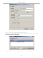
2) Setting printer’s IP address
Select the printer information to be modified (black frame appears), click “Assign IP” button. Set the
IP in the dialog box appearing.
Check the “Use DHCP” if need to assign dynamic address, the settings above will be disabled
automatically. Please make sure there is a DHCP server in the network, or the printer can not
receive an effective IP address.
When to specify static address, uncheck “Use DHCP” and fill in “IP address”, “Subnet Mask” and
“Default Gateway”. If there is no gateway in the network, fill 255.255.255.255 in the “Default
gateway”. “IP address” and “Subnet Mask” should obey the assigning rules of local LAN (Ethernet),
please enquire the administrator of networks which the printer connects to for more details.
Click “OK” to send address setting information to the specified printer. The printer takes response
after “Close this window on success” is checked, and then this dialog is closed automatically. Select
“Reload Timer” then the software will wait for the printer’s response. Generally, printer will take
response in a circle time if network connection is correct.
Click “Cancel” if you abandon the modification.
Click “Search” in the main interface again to update printer information after modifying the printer’s
IP address.
3) Report printer’s IP address
Report the printer’s IP address, which will be used in the section “Newly-install printer network driver”
or “Upgrade-install printer network driver (setting driver’s network port)”.
2.8 Wi-Fi Setting
Please use Birch network setting software WiFiConfig to set the IP address for Birch Wi-Fi interface
network printers, which can be found in the CD or downloaded from www.birch.com.tw.
Caution: The network printing function needs the operation system of Windows2000 or above.
- 14 -
BP-002 User's Manual
Caution: Wi-Fi interface transfers data through wireless network. The wireless signal may be
affected by the surrounding environment, please ensure the signal around printer
location is well enough.
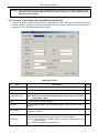
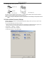
2.8.1 Connect to the Printer, Run the WiFiConfig Software
Connect the printer and the computer with the USB interface cable, make sure the printer is in normal
working condition, and then turn on both the printer and the computer, double click WiFiConfig.exe in
the driver CD. The software interface is as follows:
Explanation Table
Item
Explanation
Select a printer
Select the printer model in the list.
Refresh
Refresh the printer model.
Enter setup mode
Enter setup mode.
Note: If the printer has entered setup mode, please don’t click “Enter
setup mode” again.
Load
Load the current Wi-Fi parameter.
Baudrate
Set the serial baudrate. This parameter setting usually does not need to
change.
Flow control
Control the flow of communication data. There is no need to change this
parameter normally.
WLAN type
Select the WLAN type Infrastructure, Ad Hoc or OFF.
Infrastructure: Select infra, through router to connect network;
Ad Hoc: Select ad-hoc, wireless network card can communicate with
printer directly;
OFF: Select the printer Wi-Fi interface off.
- 15 -
Note
BP-002 User's Manual
SSID
Network name.
The longest network name is 32 characters and there is no space
between characters.
When WLAN type Infrastructure, the network name is the same with the
router’s network name;
When WLAN type Ad Hoc, the network name is the same with the
wireless network card’s network name.
Security
Select the security mode.
Key
Enter the corresponding key.
When “Security” is selected to “None”, do not need to enter key.
Use DHCP
Select to use dynamic IP assignment or not. There is no need to change
this parameter normally.
Note: Dynamic IP assignment is uncertain, it is easy lead to
unsuccessful communication because of IP mismatching, so
we don’t suggest using dynamic assignment.
Local IP
IP address of printer Wi-Fi interface.
Note: This IP address should not conflict with other network
devices.
If “Use DHCP” has been selected, then this IP is invalid.
Subnet mask
The subnet mask of printer Wi-Fi interface.
Local port
The local port of printer Wi-Fi interface. It is suggested using 9100.
Remote IP
The remote IP is a segment of the LAN or the PC IP which communicates
with printer.
When filling in IP, such as “192.168.0.1”, PC is communicate with printer
respectively; When filling in segment, such as “192.168.0”, the PCs in this
segment all can communicate with the printer.
Recover default
Recover the default setting.
After recover the default setting, you should set the Wi-Fi parameters
again.
Save
Save the setting parameter. After saving, please reboot the printer.
Press F1 to get help
Press F1 to get the help information.
2.8.2 Set Wi-Fi Parameters
Note: 1. You should use the USB interface cable to connect the printer and computer before
configuring Wi-Fi parameters, and run the WiFiConfig software.
2. Configuring Wi-Fi parameters should in the setup mode (besides recover the default
setting).
3. You should make sure the printer is in normal working condition before running the
WiFiConfig software.
The detail parameter configuration instruction and cautions please refer to the Help of WiFiConfig.exe.
Press F1 to pop up the Help instruction when running that software.
1. Connect the printer and the computer with a USB interface cable, and then turn on both the printer
and the computer, run the WiFiConfig software.
2. Check if the corresponding printer model is in the list of Select a printer, if no, please click “Refresh”,
select the corresponding printer model after it appears.
3. Click “Enter setup mode”, it will pop up a Success dialog box when it enters the mode successfully.
After entering setup mode, printer could not receive print data, and you should restart the printer
before printing.
- 16 -
BP-002 User's Manual
4. Click “Load”, the printer would load the current Wi-Fi setting.
5. Sets the network communication parameters.
Please set the corresponding network communication parameters according to the actual network
circumstances. The detailed information please enquire the network administer.
WLAN type: Select the network mode. Through hotspot, connect the network with router mode,
select “Infrastructure”; Wireless network card communicates with the printer directly,
select “Ad Hoc”; Do not need the Wi-Fi printing function, select “OFF”.
SSID: SSID is the corresponding network name. When “WLAN type” is selected to “Infrastructure”,
network name and the router network name should be the same; when “WLAN type” is
selected to “Ad Hoc”, network name and the wireless network card name should be the same.
Security: Select the security mode of the selected network.
Key: Enter the key of the selected network. When “Security” is selected to “None”, you do not need
to enter key.
6. Set the printer IP parameters.
Please set the corresponding printer IP parameters according to the actual network circumstances.
The detail information please enquire the network administer.
Note: Dynamic assign IP is uncertain, it is easy lead to unsuccessful communication because
of IP mismatching, so we don’t suggest using dynamic assignment.
IP address and subnet mask should obey the assignment rule of the local LAN.
Use DHCP: Select to use dynamic IP assignment or not. When select “Use DHCP”, the IP parameters
would be invalid. Please ensure there it DHCP server in the network firstly, or else the
printer would not achieve the valid IP address. Do not select “Use DHCP”, you should
specify static address.
Local IP: The IP address of printer Wi-Fi interface.
Subnet mask: The subnet mask of printer Wi-Fi interface.
Local port: The local port of the printer Wi-Fi interface. It is suggested using 9100.
Record the printer IP address and port number, the IP address and port number would use in the
Newly-install way or Upgrade-install way in next chapter.
7. Setting remote IP parameters.
The remote IP is a segment of the LAN or the PC IP which communicates with printer.
When filling in IP, such as “192.168.0.1”, PC communicates with printer respectively; when filling in
segment, such as “192.168.0”, the PCs in this segment all can communicate with the printer.
8. After finish setting, click “Save” to save the setting and then restart the printer.
2.8.3 Checking Wi-Fi Parameters
After setting Wi-Fi network parameters, you should check the parameters to ensure the Wi-Fi network
connection is properly.
1. Through “ping” command to check if the printer connects to network or not.
2. When “WLAN type” is select to “Infrastructure”, you could look into the Wi-Fi indicator lights to judge
the connection status.
Indicator Lights Description
Light
Network
Infrastructure
Ad Hoc
OFF
Connect
ON
ON
BLINK
Disconnect
BLINK
ON
BLINK
Communication
- 17 -
BP-002 User's Manual
2.8.4 Recover the Default Setting
When the malfunctions of the Wi-Fi parameters lead to the printer unable to connect with the network,
you could recover the default setting to set the parameters again.
Note: Printer does not need to enter setup mode when recovering the default setting. If the
printer has entered into setup mode, please restart the printer before recovering the
default setting.
1. Connect the printer and the computer with a USB interface cable, and then turn on both the printer
and the computer and run the WiFiConfig software.
2. Check if the corresponding printer model is in the list of Select a printer, if no, please click “Refresh”,
select the corresponding printer model after it appears.
3. Click “Recover default”, wait several seconds and a dialog box would pop up to denote the recovery
is successful or not.
4. After finishing recovering, please restart the printer and set the Wi-Fi parameters again.
2.9 Installing Printer Network Driver
The ways of installing network driver are classified into Newly-install way and Upgrade-install way
according to whether the PC installs the printer driver or not.
If the printer driver hasn’t been installed on the PC, adopt newly-install way whose steps are shown in
“Newly-install printer network driver”.
If the printer driver has been installed on the PC, adopt Upgrade-install way whose steps are shown in
“Upgrade-install printer network driver”.
1. Newly-install printer network driver
1) Click “Start” → “Settings” → “Select Printers”.
2) Click “Add printer”, then a window of “Add Printer Wizard” pops up, click “next”, then please read
the select guide carefully. Such as, select “Local or Network Printer”, then click “next”.
3) A window of “Select the Printer port” pops up, select a port you want your printer to use. For
example, select “Create a new port”, select “Standard TCP/IP Port” in the port, click “next”.
4) A window of “Add standard TCP/IP Printer Port Wizard”, click “Next”.
- 18 -
BP-002 User's Manual
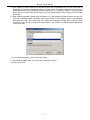
5) A window of “Add Port” pops up, enter the IP address reported by the “Setting printer’s IP
address” in the “Printer Name or IP Address” column. Take IP address “192.168.0.240” for
example. “Port Name” is created automatically after finishing filling in IP address.
6) A window of “Additional Port Information Required” pops up, select “Custom” in the “Device Type”,
then click “Settings”.
7) A window of “Port Settings” pops up. Affirm that “Port name” and “Printer name or IP address” are
correct, “Protocol” is “RAW” and “Port Number” is “9100”, click “OK”.
- 19 -
BP-002 User's Manual
8) Return to “Additional Port Information Required”, click “Next”.
9) A window of “Completing the Add Standard TCP/IP Printer Port Wizard” pops up, click “Finish”.
10) In the selection of “Manufacturers/Printers”, click “Have Disk”, and then click “Next”.
11) A window of “Install From Disk” pops up. Please according to the operating system environment,
such as Windows 2000/XP/Vista/Win7 operating system you should select the path as follows:
CD-ROM → “Driver” → “WIN2000 (XP-Vista-Win7)”, click “Open”, then click “OK” to return to
the window of “Install Printer Software”, select the respective model, click “Next”.
12) Follow the direct click “next” gradually till the installation is finish. At this time, printer network
driver is installed completely.
2. Upgrade-install printer network driver (setting driver’s network port)
If PC has installed the printer’s driver, set driver’s network port to carry out network printing. The
concrete steps are shown below:
1) Click “Start” → “Settings” → “Select Printers”.
2) Right click BP-002 driver, click “Properties” on the window popping up.
3) A window of “Properties” pops up, click “Ports” and “Add Ports”.
- 20 -
BP-002 User's Manual
4) A window of “Printer port” pops up, select “Standard TCP/IP Port”, click “New port”.
5) A window of “Add Standard TCP/IP Printer Port Wizard” pops up, click “Next”.
6) A window of “Add a port” pops up, import the IP address reported by the “Setting printer’s IP
address” in the “Printer name or IP address” column. Take IP address “192.168.0.240” for example.
“Port name” is created automatically after finishing filling in IP address. Click “Next”.
- 21 -
BP-002 User's Manual
7) A window of “Additional Port Information Required” pops up, select “Custom” in the “Device Type”,
then click “settings”.
8) A window of “Port Settings” pops up. Affirm that “Port name” and “Printer name or IP address” are
correct, “Protocol” is “RAW” and “Port Number” is “9100”, click “OK”.
- 22 -
BP-002 User's Manual
9) Return to “Additional Port Information Required”, click “Next”.
10) A window of “Completing the Add Standard TCP/IP Printer Port Wizard” pops up, click “Finish”.
11) Return to “Printer Ports”, click “Close”.
12) Return to “Properties”, make sure the network port is selected, click “Apply”, and then click “Close”.
Thus, printer’s network port setting is finished.
- 23 -
BP-002 User's Manual
- 24 -
BP-002 User's Manual
Chapter 3 Control Panel
3.1 Control Panel
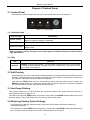
There are three indicator lights and one key on the control panel shown as Figure 3-1.
Figure 3-1 Control panel
3.1.1 Indicator light
Indicator light
Description
POWER (Green)
Denotes whether the printer’s power supply is connected or not. The indicator
light is on when the power is connected.
ERROR (Red)
Denotes printer’s status. The indicator light is on when the malfunction appears.
PAPER OUT (Red)
Denotes printer’s paper status. The indicator light is on when paper end or is
about to end.
Refer to chapter 6.2 Error message on the control panel for detailed information about indicator
light malfunctions.
3.1.2 Key
Key
Function
【FEED】
【FEED】controls paper feeding, you can enable or disable the button’s function with
a command. When enabled, the paper will be fed continuously if you press and hold
on it, or stop if you loosen it.
3.2 Self-Printing
Self-printing lets you know if the printer is working properly. If the printer printouts the self-test content
normally, it denotes that there is nothing wrong with the printer except for the interface connecting to
the computer. Otherwise, the printer should be repaired.
Hold down the FEED button and turn on the power switch while the printer cover is closed, the
ERROR indicator blinks once, loosen the button, then the printer will print out self-test information
such as the software version, update date and interface etc.
3.3 Hex Dump Printing
This function allows you to check whether the connection between the printer and the computer or
terminal device works properly or not.
The method is that press FEED button and power on the printer, the ERROR indicator blinks twice, then
loose the button. Turn off the printer when you want to exit this print mode.
3.4 Restoring Factory Printer Settings
The function is to clear the settings stored in the printer and to restore the factory settings for
correlative parameters.
The method is that press FEED button and power on the printer, the ERROR indicator light blinks three
times, and then loose the button, the function is finish and turn off the printer.
- 25 -
BP-002 User's Manual
3.5 Setting Slip Stitch (UPDATE and BOOT)
Slip Stitch Cap
Slip Stitch
When Plugging Into
When Pulling Out
Slip Stitch is used to upgrade printer firmware. In normal working condition, BOOT slip stitch should be
pulling out while UPDATE slip stitch should be plugging into.
Note: Do not change the Slip Stitch without any permission of the factory, or the printer can not
work.
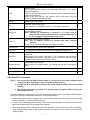
3.6 Online-aptitude Parameter Settings
BP-002 supports the function of online-aptitude parameter settings, which can be set in the PC with
the driver installed in.
The concrete setting steps are shown as follows:
1. Make sure that the computer and the printer are connected with a cable and both the computer and
the printer are turned on, the printer should be in normal working condition as well.
2. Click “Start” → “Settings” → “Printers”.
3. Right click “BP-002”, select “Properties”.
4. Click “Printer settings” in the property page.
- 26 -
BP-002 User's Manual
5. In the window of Printer Settings, the left side of each item is parameter icon, the top right corner is
parameter item and the bottom right corner is current value. The printer will load the current value
automatically when each parameter window popping up. If the printer is offline or using improper
printer port, the current value will be blank, then, you should set the printer online or use the proper
printer port.
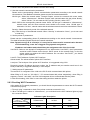
6. When setting parameter, please click parameter icon, then parameter setting window will pop up,
there are parameter items, decription and control button in this window. Select corresponding
parameter and click “Set”, the printer will change the parameter settings after receiving setting
command. Click “Cancel” to back to the upper window, click “Default” to show the default parameter
of this menu item.
7. To set other parameters, refer to the upper setps.
8. After finishing setting, click “OK” to exit the “Properties” window.
9. Reboot the printer.
- 27 -
BP-002 User's Manual
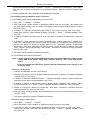
Chapter 4 Installing Paper
The printer can install the paper conveniently, which should be 58mm wide. How to deal with the paper
will be explained in details in this chapter.
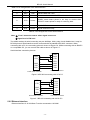
4.1 Paper Installation Steps
Note: 1. Don’t touch the thermal print head after printing to avoid being burned.
2. Don’t pull the paper moving directly with your hand.
1. Push the cover-opening button, open the upper cover.
Upper Cover
Figure 4-1 Open the upper cover
2. Insert the roll paper as shown below.
Roll Paper
Correct
Error
Figure 4-2 Insert the roll paper
Note: Paper head should be pulled out by the direction of paper-input slot, but not the opposite.
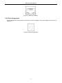
3. Pull out a small amount of paper.
- 28 -
BP-002 User's Manual
Figure 4-3 Pull out the paper
4. Put the paper as shown below, and then close the cover.
Figure 4-4 Close the cover
NOTE: After finishing installing the paper, if PAPER OUT indicator light and ERROR indicator
light are still on, or the printer makes strange noise when feeding paper, please open the
cover and re-close it tightly.
- 29 -
BP-002 User's Manual
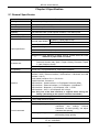
Chapter 5 Specification
5.1 General Specificaion
Item
Description
Printing method
Thermal line printing
Printing direction
Line by line
Dot density
384 dots/ line (203×203 DPI)
Printing speed
100 mm/s
Reliability
Print head life:50Km (under special condition), 100 million pulse
Effective printing width
48 mm
Paper feed speed
100 mm/s (Max.)
Thermal paper Model
TF50KS-E (Japan paper co.ltd)
AF50KS-E (JUJO THERMAL)
Width: 57.5 ± 0.5 mm
Paper specificaion
Weight: 53 ~ 80 g/m2
Outer diameter: Φ83 mm (Max.)
Thickness: 0.065 ~ 0.15mm
*Suggestion: Inner diameter of paper shaft is Φ12mm while the outer
diameter of paper shaft is Φ18mm.
Character set
ASCII: 14 international character sets (America, France, Germany, U.K.,
Denmark, Sweden, Italy, Spain I, Japan, Norway, Denmark II, Spain
II, Latin America, Korea)
Chinese: Big 5 or GB 18030
Line spacing
30/203 inch, or programmable in 1/203 inch increments
Interface
Cash drawer interface + data interface (parallel interface, USB + serial
interface, USB + Ethernet interface, USB interface + Bluetooth and USB
interface + Wi-Fi)
Cash drawer interface: RJ-11, DC12V/1A
Parallel interface: Centronics
USB interface + Serial interface: 2.0 Full-Speed, RS-232C (DB9)
USB interface + Ethernet interface: 2.0 Full-Speed, 10/100Base-T
USB interface + Bluetooth: 2.0 Full-Speed, 2.0/2.1 + EDR
USB interface + Wi-Fi: 2.0 Full-Speed, 802.11b/g/n
Note: Only one of the data interfaces is supplied when leaving the
factory. (According to the specific interface standards.)
Special function
Online parameter settings, Software online update
Buffer memory
2 KB or 6KB (Ethernet model)
ESC/POS Emulation
Control command
Character printing command: Support ANK characters, user-define
characters
and
enlarge
Chinese
characters 1-2 times printing, can adjust
character line spacing
Dot image printing command: Support different densities dot images and
downloading image printing
Linear bar code: UPC-A, UPC-C, EAN-13, EAN-8, CODE39, CODE128,
ITF-25, CODABAR
- 30 -
BP-002 User's Manual
IN
Power Supply
OUT
Environmental
conditions
Operating
environment
Storage
environment
Input voltage: 100 ~ 240 VAC
Frequency: 50Hz/60Hz
Output voltage: 8.5V DC
Current: 3 A
Temperature: 5 ~ 40℃
Humidity: 20%RH ~ 80%RH (No condensation)
Temperature: -40 ~ 55℃
Humidity: ≤93%RH (40℃, No condensation)
Weight
Approx.1 Kg
Noise
<38 dB (A) (ISO7779 standard)
Physical dimensions
120 mm (Width) × 192 mm (Depth) × 130 mm (Height)
Power
①Operation power: 27 W; ②Maximum power: 42 W; ③Standby power:
1.3 W.
Note: Only when the product doesn’t connect with any power supply,
can it consume zero energy.
Dot spacing
ASCII dot matrix
Vertical: 0.125 mm
Horizontal: 0.125 mm
12 (width) × 24 (height)
9 (width) × 17 (height)
ASCII size
1.50 (width) × 3.00 (height) mm
Chinese dot matrix
24×24
Chinese size
3.00 (width) × 3.00 (height) mm
Characters per line
Paper feed mode
Average no malfunction
period
ASCII 32 (12×24 dot matrix)
Chinese 16 (24×24 dot matrix)
Unidirectional with friction feed
5 million lines
Code page
0: PC437(Std.Europe), 1: PC437, 2: PC850(Multilingual), 3:
PC860(Portuguese), 4: PC863(Canadian), 5: PC865(Nordic), 10: Iran, 15:
IranⅡ, 16: PC1252, 17: PC866, 18: PC852, 19: PC858, 20: Thai(KU42),
21: Thai(TIS11), 22: PC1256(Arabic), 26: Thai(TIS18), 27: Vietnam, 28:
PC864(Arabic), 29: PC737(Greek), 61: PC857(Turkish), 62: Hebrew, 70:
Thai, 74: PC3840(Russian), 79: PC1254(Turkish), 255:Thai
Paper cut
Cut manually (Note: Without auto-cutter)
Control panel
1 button and 3 indicator lights
Wireless disturb
Grade B
Caution: In order to ensure the use life of printer, strictly prohibit printing full line full black
exceeding 2 CM.
5.2 Interface Specifications
The printer is configured with one cash drawer interface and one data interface group (Parallel
interface, USB interface + Serial interface, USB interface + Ethernet interface, USB interface +
Bluetooth or USB interface + Wi-Fi according your need).
5.2.1 Cash Drawer Interface
The cash drawer interface of the printer uses the RJ-11 connector, which is shown below.
- 31 -
BP-002 User's Manual
6
1
Figure 5-1 Cash drawer connector
Table A-1: Cash drawer connector Pin assignments
Pin number
Signal
Direction
1
Frame GND
---
2
Cash Drawer drive signal
OUT
3
4
5
Cash Drawer open/closed signal
12VDC
Cash Drawer drive signal
IN
OUT
OUT
6
Cash Drawer open/closed signal ground
Drive current≤12V/1A
---
Table A-1: Cash drawer connector Pin assignments
Note: Make sure the cash drawer meets the specification mentioned above, or we will not
guarantee to keep the printer in good repair.
5.2.2 Parallel Interface
BP-002 printer’s parallel interface is compatible with CENIRONICS protocol, supporting BUSY/ACK
handshaking protocol.
The connector is a 36-PIN connector, whose pins are shown as below.
Figure 5-2 Parallel interface
Table A-2: Connector Pin Assignments
Pin number
1
9
Signal
/STB
DATA1
DATA2
DATA3
DATA4
DATA5
DATA6
DATA7
DATA8
Direction
IN
IN
IN
IN
IN
IN
IN
IN
IN
10
/ACK
OUT
11
12
13
BUSY
PE
SEL
OUT
OUT
OUT
2
3
4
5
6
7
8
Description
Trigger in low level, read the data in rising edge
These signals are respective represent the parallel
data from the first bit to the eight. “1” means high
level, while “0” means low level.
Acknowledge signal, Low level means that printer is
ready for receiving data.
High level means printer is too busy to receive data.
High level means that paper is out.
High level with the pull-up resistor.
- 32 -
BP-002 User's Manual
32
14, 15, 17, 18,
34, 36
16, 19~30, 33
/ERR
OUT
Low level means the printer is in error state
NC
---
Not connect
GND
---
GND, “0” level in logic
Table A-2: Connector Pin Assignments
Note: ① “IN” means input to the printer, “OUT” means output from printer.
② The signal logical level is TTL level.
Relative signal is shown as Figure 5-3.
BUSY
/ACK
DATA
/STB
0. 5μS
0. 5μS
0. 5μS
0.5μS
0. 5μS
Figure 5-3 Timing signal in parallel interface
5.2.3 USB Interface
USB interface interface is USB-B type interface (As Figure 5-4 shown).
2
1
3
4
Figure 5-4 USB interface
Interface connector A and B’s signal wire assignment is as Table A-3 shown:
Contact Number
1
2
3
4
Signal Name
VBUS
DD+
GND
Typical Wiring Assignment
Red
White
Green
Black
5.2.4 Serial Interface
BP-002 printer’s serial interface is compatible with RS-232C protocol, supporting RTS/CTS and
XON/XOFF handshaking protocol. Its connector is a DB-9 type connector and each pin’s definitions
are shown as below.
Figure 5-5 Sequence numbers of Serial connector
- 33 -
BP-002 User's Manual
Table A-4 Pin assignments of the serial interface
Pin Number
Signal
From
Description
2
RXD
Host
3
TXD
Printer
Sent control code X-ON/X-OFF and data to the Host
8
CTS
Printer
“MARK” state means printer is too busy to receive data;
“SPACE” means printer is ready for receiving data.
5
GND
—
4
DTR
Printer
Receive data from Host
Signal GND
Signal terminal is ready
Table A-4 Pin assignments of the serial interface
Note: ① “From” means the source where signal comes out.
② Signal level is EIA level.
The default settings in serial connecting way are 9600bps, 8 bits, parity check disabled and 1 stop bit.
BP-002 printer’s serial interface can be connected with the standard RS-232C connector. When
connecting with a PC, the connecting picture is shown as Figure 5-6. While connecting with an IBM PC
or a compatible PC, you can connect the cable as shown in Figure 5-7.
Serial interface connection pictures:
6
DTR
CTS
4
1
8
8
GND
TXD
RXD
5
5
3
2
2
3
DSR
DCD
CTS
RTS
GND
RXD
TXD
7
Host 9-Pin connector
Printer 9-Pin connector
Figure 5-6 BP-002 connecting with 9-Pin PC
6
DTR
CTS
4
8
8
5
GND
TXD
RXD
5
7
3
3
2
2
4
Printer 9PIN connector
DSR
DCD
CTS
RTS
GND
RXD
TXD
Host 25PIN connector
Figure 5-7 BP-002 connecting with 25-Pin PC
5.2.5 Ethernet Interface
Ethernet interface of 10/100 Base-T can be connected to 10/100M.
- 34 -
BP-002 User's Manual
Figure 5-8 Ethernet interface
5.2.6 Power Supply Inlet
The BP-002 printer connects with a 8.5V±5% and 3A AC adapter. The power supply inlet is shown as
Figure 5-9.
Figure 5-9 Power supply inlet
- 35 -
BP-002 User's Manual
Chapter 6 Troubleshooting and Maintenance
6.1 Maintenance
To prolong the printer’s life, make sure that the printer is well away from heaters and other sources of
extreme heat, and the surrounding area is clean, dry, and free of dust.
Cleaning paper holder and thermal print head periodically is the main task of maintaining the printer.
We will speak about this problem in this section. It is noted that make sure to turn off the printer before
maintenance.
Printer Cleaning:
Dirt and dust do the most damage to the printer. Clean the paper in the printer and accumulated dirt in
the thermal head as well despite the outer case of the printer prevents greater part of dust from
invading.
Clean Printer Case:
Remove the dirt in the printer case with clean, soft cloth, and take out the paper pieces with a nipper.
Attention: Be careful not to scratch the printer parts when cleaning.
Clean the printer periodically according to the prescription as follows.
z
Periodically cleaning: Once every 6 months or 300 working hours
z
Cleaning tool: Dry cloth (Soft cloth if metal parts)
6.2 Error Message on the Control Panel
When the malfunction occurs, the printer will be off-line and give an alarm through indicator lights. You
can make out different malfunctions through the following table.
Error indicator
PAPER OUT indicator
Malfunction
Solution
ON
OFF
Cover is open
Close the cover tightly
ON
ON
Paper out
Load the paper again
Blink
OFF
Print head overheated
Recover automatically
- 36 -
BP-002 User's Manual
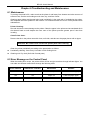
Chapter 7 Control Commands
7.1 General
The commands BP-002 supplies are based on ESC/POS.
The format described as following:
Command
Function
Format:
ASCII:
Decimal:
Hex:
Indicates the ASCII equivalents
Indicates the decimal equivalents
Written in hexadecimal code
Description: The function and using instruction of that command.
Example: Some examples are listed for easier understanding.
7.2 Explanation of Terms
HT
Horizontal tab
Format:
ASCII:
Decimal:
Hex:
HT
9
09
Description:
Move the print position to the next horizontal tab position
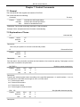
LF
Print and line feed
Format:
ASCII:
LF
Decimal:
10
Hex:
0A
Description:
Print the data in the print buffer and feed one line based on the current line spacing. Feed paper one line
when there is no data in the print buffer.
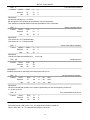
DLE EOT n
Format:
Real-time status transmission
ASCII:
DLE
EOT
n
Decimal:
16
4
n
Hex:
10
04
n
Description:
Transmit the selected printer status according to the specified parameter n in serial interface, 1<=n<=4;
this instruction is still valid even thought in error or off-line status.
n=1: Transmit print status
n=2: Transmit off-line status
n=3: Transmit error status
n=4: Transmit paper roll sensor status
ESC
SP
Format:
Set right-side character spacing
ASCII:
Decimal:
Hex:
ESC
SP
n
27
32
n
1B
20
n
Description:
- 37 -
BP-002 User's Manual
Set the right-side spacing of the character to n*(horizontal or vertical motion unit)
n=0~255.
Horizontal or vertical motion unit is specified by GS P command
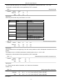
ESC
Set print mode
!
Format:
ASCII:
ESC
!
n
Decimal:
27
33
n
Hex:
1B
21
n
Description:
Select the print mode using n as follows. n=0~255
Bit
0
1,2
3
4
5
6
7
ESC
Value
0
1
-- -- -0
1
0
Function
Character A
Character B
Not define
Emphasize mode not selected
Emphasize mode selected
Double-height not selected
1
0
1
Double-height selected
Double-width not selected
Double-width selected
Not define
Underline mode not selected
Underline mode selected
-- -- -0
1
$
Format:
Set absolute print position
ASCII:
ESC
$
nL
nH
Decimal:
27
36
nL
nH
Hex:
1B
24
nL
nH
Description:
Set the distance from the beginning of the line to the position at which subsequent characters are to be
printed.
The distance is (nL+nH*256)* (horizontal or vertical motion unit). nL, nH=0~255.
Horizontal or vertical motion unit are specified by GS P command.
ESC %
Format:
Selected/cancel user-define characters set
ASCII:
ESC
%
n
Decimal:
27
37
n
Hex:
1B
25
n
Description:
n=1, Select the user-define characters; n=0, Select inter characters.
Default: n=0
ESC
&
Format:
Define user-define characters
ASCII:
Decimal:
Hex:
ESC
&
y c1 c2
27
38 y
1B
26
[x1 d1..d(y*x1)]
[xk d1..d(y*xk)]
c1 c2 [x1 d1..d(y*x1)]
[xk d1..d(y*xk)]
y c1
c2
[x1 d1..d(y*x1)]
Description:
- 38 -
[xk d1..d(y*xk)]
BP-002 User's Manual
Define the user-define Characters from c1 to c2.
y=3; 32<=c1<=c2<=126;
0<=x<=12; [Character A 12*24], 0<=x<=9; [Character B 8*16];
d=0~255; k=c2-c1+1≤10; that is to say each time define characters could not over 10;
y specifies the number of bytes in the vertical direction, x specifies the number of dots in the horizontal
direction, d specifies the user-define data.
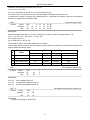
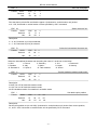
ESC *
Format:
Select bit-image mode
ASCII:
Decimal:
Hex:
ESC
27
1B
*
42
2A
m
m
m
n1
n1
n1
n2
n2
n2
d1..dk
d1..dk
d1..dk
Description:
Select the image mode with m; n1 and n2 specify the number of dots; the image data d1…dk
m=0, 1, 32, 33; n1=0~ 255; n2=0~3; d=0~255.
k=n1+256×n2 (m=0, 1)
k= (n1+256×n2) × 3 (m=32, 33)
The number of dots in horizontal direction is n1+256×n2.
If the number dots exceed the max dot number in a line (shown as below), the excess data is ignored. M is
used to select dots image mode.
M
Vertical direction
Mode
Horizontal direction
Number of dots
Dot density
Dot density
Number of dots (max)
0
8-dot single-density
8
68DPI
101DPI
288
1
8-dot double-density
8
68DPI
203DPI
576
32
24-dot single-density
24
203DPI
101DPI
288
33
24-dot double-density
24
203DPI
203DPI
576
ESC
-
Turn underline mode on/off
Format:
ASCII:
Decimal:
Hex:
ESC
-
n
27
45
n
1B
2D
n
Description:
n=0, 48
n=1, 49
n=2, 50
ESC
Turn underline mode off.
one-dot thick underline mode on
two-dot thick underline mode on
2
Format:
Set default line spacing to 30/203 inch
ASCII:
ESC
2
Decimal:
27
50
Hex:
1B
32
Description:
Set the line spacing to 30/203 inch.
- 39 -
BP-002 User's Manual
ESC
3
Format:
User-define line spacing
ASCII:
ESC
3
n
Decimal:
27
51
n
Hex:
1B
33
n
Description:
Set the line spacing to n*. n=0~255.
BP-002 printer’s line spacing is the minimum unit of horizontal n*
The vertical or horizontal motion units are specified by GS P Command.
ESC
=
Format:
Select peripheral device
ASCII:
Decimal:
Hex:
ESC
=
n
27
61
n
1B
3D
n
Description:
The Last bit of n is 0, printer disable.
The Last bit of n is 1, printer enable.
ESC
?
Format:
Cancel user-define character
ASCII:
Decimal:
Hex:
ESC
?
n
27
63
n
1B
3F
n
Description:
Cancel the character specified by n. n=32~126.
ESC @
Format:
Initialize printer
ASCII:
ESC
@
Decimal:
27
64
Hex:
1B
40
Description:
Initialize the printer to the state when the printer was turn on.
ESC
D
Format:
Set horizontal tab position
ASCII:
ESC
D
n1……nk
NUL
Decimal:
27
68
n1……nk
NUL
Hex:
1B
44
n1……nk
NUL
Description:
Set the horizontal tab position to the column specified by nk from the beginning of the line.
n = 0~255; k=0~32;
ESC
E
Format:
Turn emphasized mode on/off
ASCII:
ESC
E
n
Decimal:
27
69
n
Hex:
1B
45
n
Description:
When the last bit (LSB) of the n is 0, the emphasized mode is turned off.
When LSB of the n is 1, the emphasized mode is turned on.
- 40 -
BP-002 User's Manual
ESC
J
Print and feed paper
Format:
ASCII:
ESC
J
n
Decimal:
27
74
n
Hex:
1B
4A
n
Description:
Print the data in print buffer and feed the paper n*(horizontal or vertical motion unit) inches.
n=0~255; Horizontal or vertical motion unit are specified by GS P command.
ESC
M
Format:
Select character font
ASCII:
ESC
M
n
Decimal:
27
77
n
Hex:
1B
4D
n
Description:
n = 0, 48; Character A (12*24) is selected;
n = 1, 49; Character B (8*16) is selected.
ESC
R
Format:
Select the international character set
ASCII:
ESC
R
n
Decimal:
27
82
n
Hex:
1B
52
n
Description:
Select the international character set according the value of n as shown in the follow.
0: USA
1: France
2: Germany
3: U.K
4: Denmark I
5: Sweden
6: Italy
7: Spain I
8: Japan
9: Norway
10: Denmark II
11: Spain II
12: Latin America
13: Korea
ESC
V
Format:
Turn 90°clockwise rotation mode on/off
ASCII:
ESC
V
n
Decimal:
27
86
n
Hex:
1B
56
n
Description:
n=0,48 Turn off 90°clockwise rotation mode.
n=1,49 Turn on 90°clockwise rotation mode.
No 90°clockwise rotation for underline in underline mode.
ESC \
Format:
Set relative print position
ASCII:
ESC
\
nL
nH
Decimal:
27
92
nL
nH
Hex:
1B
5C
nL
nH
Description:
Set the print position at (nL+nH*256)* (horizontal or vertical motion unit) inches from current position;
nL, nH=0~255. Horizontal or vertical motion unit is specified by GS P command.
- 41 -
BP-002 User's Manual
ESC a n
Format:
Select justification
ASCII:
ESC
a
n
Decimal:
27
97
n
Hex:
1B
61
n
Description:
n=0, 48: Left justification; n=1, 49: centering; n=2, 50; right justification.
ESC c 5
Format:
Enable/disable panel button
ASCII:
ESC
Decimal:
Hex:
c
5
n
27
99
53
n
1B
63
35
n
Description:
When the LSB of n is 0, enable button.
When the LSB of n is 1, disable button.
ESC d
Print and feed n lines
Format:
ASCII:
Decimal:
Hex:
ESC
c
n
27
100
n
1B
64
n
Description:
Print the data in print buffer and feed n lines, n= 0~255.
ESC
p m t1 t2
Format:
ASCII:
Generate pulse
ESC
p
m
t1
t2
Decimal:
27
112
m
t1
t2
Hex:
1B
70
m
t1
t2
Description:
Printer output pulse, whose width specified by t1 and t2. On time is t1*2ms, low is t2*2ms.
m=0, 48, 1, 49.
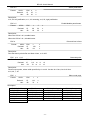
ESC
t
Format:
Select code page
ASCII:
ESC
t
n
Decimal:
27
116
n
Hex:
1B
74
n
Description:
n=0 PC437(Std.Europe)
n=4 PC863(Canadian)
n=16 PC1252
n=20 Thai(KU42)
n=27 Vietnam
n=62 Hebrew
n=255 Thai
n=1 PC437
n=5 PC865(Nordic)
n=17 PC866
n=21 Thai(TIS11)
n=28 PC864(Arabic)
n=70 Thai
n=2 PC850(Multilingual)
n=10 Iran
n=18 PC852
n=22 PC1256(Arabic)
n=29 PC737(Greek)
n=74 PC3840(Russian)
- 42 -
n=3 PC860(Portuguese)
n=15 IranII
n=19 PC858
n=26 Thai(TIS18)
n=61 PC857(Turkish)
n=79 PC1254(Turkish)
BP-002 User's Manual
ESC {
Format:
Turn on/off upside-down printing mode
ASCII:
Decimal:
Hex:
ESC
{
n
27
123
n
1B
7B
n
Description:
When the LSB of n is 0, upside-down printing mode is turn off.
When the LSB of n is 1, upside-down printing mode is turn on.
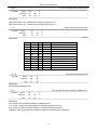
FS !
Select Chinese character mode
Format:
ASCII:
FS
!
n
Decimal:
28
33
n
Hex:
1C
21
n
Description:
Bit
0
1
2
Off/On
Off
On
Off
On
Off
On
3
4
5
6
7
FS
Hex
00
04
00
08
00
80
Decimal
0
4
0
8
0
128
&
Format:
Function
Not define
Not define
Double-width is not selected
Double-width is selected
Double-height is not selected
Double-height is selected
Not define
Not define
Not define
Underline is not selected
Underline is selected
Set Chinese language mode
ASCII:
FS
&
Decimal:
28
38
Hex:
1C
26
Description:
Set Chinese language mode
FS
-
Format:
Turn Chinese character underline mode on /off
ASCII:
FS
-
n
Decimal:
28
45
n
Hex:
1C
2D
n
Description:
n=0, 48 turn off the Chinese character underline mode.
n=1, 49 turn one dot the thick underline of Chinese character mode on.
n=2, 50 turn two dots the thick underline of Chinese character mode on.
Underline mode is ignored if 90°clockwise rotation is turned on at the same time.
- 43 -
BP-002 User's Manual
FS
Cancel Chinese language mode
.
Format:
ASCII:
FS
.
Decimal:
28
46
Hex:
1C
2E
Description:
In this mode No Chinese character printed.
FS
2
Format:
Define user-define Chinese characters
ASCII:
FS
2
c1
c2
d1……d72
Decimal:
28
50 c1 c2
d1……d72
Hex:
1C
32 c1 c2
d1……d72
Description:
c1=fe; a1<=c2<=fe; In this range, each time C2 can choose at most 6, that is to say, each time can define
6 Chinese characters at most. 0<=d<=255; c1 specified the first byte of the character code, c2 specified
the second byte of the character code. Data dk defined from up to down 3 bytes one column, and from left
to right 24 columns.
FS
S
Format:
Set Chinese character spacing
ASCII:
FS
S
n1
n2
Decimal:
28
83
n1
n2
Hex:
1C
53
n1
n2
Description:
0 ≤ n1 ≤ 255, 0 ≤ n2 ≤ 255
Set the character left-side spacing to n1*(horizontal or vertical motion unit), right-side spacing to
n2*(horizontal or vertical motion unit).
FS
W
Format:
Turn quadruple-size mode on/off for Chinese character
ASCII:
FS
W
n
Decimal:
28
87
n
Hex:
1C
57
n
Description:
0 ≤ n ≤ 255
When the LSB of n is 0, turn off the quadruple-size mode.
When the LSB of n is 1, turn on the quadruple-size mode.
GS
Select Character size
!
Format:
ASCII:
GS
!
n
Decimal:
29
33
n
1D
21
n
Hex:
Description:
n = 0, 1, 16, 17;
Selects the character height (vertical number of times normal font size) using bits0 to bits3 and selects the
character width (horizontal number of times normal size) using bits4 to bits7.
- 44 -
BP-002 User's Manual
GS
B
Format:
Turn white/black reverse mode on/off
ASCII:
GS
B
n
Decimal:
29
66
n
Hex:
1D
42
n
Description:
When the LSB of n is 0, turn the white/black reverse mode off.
When the LSB of n is 1, turn the white/black reverse mode on.
GS
H
Format:
Select print position of HRI character
ASCII:
GS
H
n
Decimal:
29
72
n
1D
48
n
Hex:
Description:
n=0, 48: NO HRI printing. n=1, 49: above the barcode. n=2, 50: above the barcode. n=3, 51: Both above
and below.
GS
L
Format:
Set left margin
ASCII:
GS
L
nL
nH
Decimal:
29
76
nL
nH
Hex:
1D
4C
nL
nH
Description:
Set the left margin to (nL+nH*256)*(horizontal or vertical motion unit); nL, nH=0~255.
Horizontal or vertical motion unit is specified by GS P command.
GS
P
Format:
Set horizontal or vertical motion unit
ASCII:
GS
P
x
y
Decimal:
29
80
x
y
Hex:
1D
50
x
y
Description:
Set the horizontal and vertical unit to 1/x inch and 1/y inch.
When x or y=0, the default 1/203 inch is selected.
GS
W
Format:
Set print area width
ASCII:
GS
W
nL
nH
Decimal:
29
87
nL
nH
Hex:
1D
57
nL
nH
Description:
Set the print area width to (nL+nH*256)* (horizontal or vertical motion unit), nL, nH=0~255.
Horizontal or vertical motion units are specified by GS P.
GS
f
Format:
Select the HRI character font
ASCII:
GS
f
n
Decimal:
29
102
n
Hex:
1D
66
n
Description:
Select the HRI character when printing a bar code, using n as follows:
n=0, 48; Selects character A (12*24)
- 45 -
BP-002 User's Manual
n=1, 49; Selects character B (8*16)
GS
h
Set bar code height
Format:
ASCII:
GS
h
n
Decimal:
29
104
n
Hex:
1D
68
n
Description:
Set the height of the bar code to n dots.
n = 0 ~ 48。
GS k
Print bar code
Format:
*
ASCII:
GS
k
m
d1..dk
NUL
Decimal:
29
107 m
d1..dk
0
Hex:
1D
6B
m
d1..dk
00
ASCII:
GS
k
m
n
d1..dn
Decimal:
29
107 m
n
d1..dn
Hex:
1D
6B
n
d1..dn
m
当 m > 64 时选用格式*
m
0
1
2
3
Bar code type
UPC-A
UPC-E
EAN13
EAN8
Amount of data
Fixed
Fixed
Fixed
Fixed
The range of k
11 ≤ k ≤ 12
11 ≤ k ≤ 12
12 ≤ k ≤ 13
7≤k≤8
4
CODE39
Can be changed
1≤k
5
ITF
Can be changed
1 ≤ K (Even)
6
CODABAR
Can be changed
1≤k
*65
*66
*67
*68
UPC-A
UPC-E
EAN13
EAN8
Fixed
Fixed
Fixed
Fixed
11 ≤ n ≤ 12
11 ≤ n ≤ 12
12 ≤ n ≤ 13
7≤n≤8
character
0 ~ 9
0 ~ 9
0 ~ 9
0 ~ 9
0 ~ 9,
A ~ Z,
SP, $, %,
+, -, ., /
*(start
character)
0~9
0 ~ 9,
A ~ D,
$, +, -, .,
/, :
0 ~ 9
0 ~ 9
0 ~ 9
0 ~ 9
0 ~ 9,
A ~ Z,
SP, $, %,
+, -, ., /
*(start
character)
*69
CODE39
Can be changed
1 ≤ n < 255
*70
ITF
Can be changed
1 ≤ n ≤ 255
(Even)
0 ~ 9
*71
CODABAR
Can be changed
1 ≤ n ≤ 255
0 ~
A ~
- 46 -
Character code
48 ≤ d ≤ 57
48 ≤ d ≤ 57
48 ≤ d ≤ 57
48 ≤ d ≤ 57
48 ≤ d ≤ 57, 65 ≤ d ≤ 90, d =
32, 36, 37, 43, 45, 46, 47. d =
42
(start character)
48 ≤ d ≤ 57
48 ≤ d ≤ 57, 65 ≤ d ≤ 68, 36,
43, 45, 46, 47, 58
48 ≤ d ≤ 57
48 ≤ d ≤ 57
48 ≤ d ≤ 57
48 ≤ d ≤ 57
48 ≤ d ≤ 57, 65 ≤ d ≤ 90d =
32, 36, 37, 43, 45, 46, 47. d =
42
(start character)
48 ≤ d ≤ 57
9,
D,
48 ≤ d ≤ 57, 65 ≤ d ≤ 68, 36,
43, 45, 46, 47, 58
BP-002 User's Manual
$, +, -, .,
/, :
*73
CODE128
Can be changed
2 ≤ n < 255
NUL
~
SP(7FH)
0 ≤ d ≤ 127
GS v 0
Format:
Print raster bit image
ASCII:
GS
Decimal:
v
29
Hex:
0
m
xL xH
yL yH
d1…dk
118 48
m
xL xH
yL yH
d1…dk
m
xL xH yL yH
d1…dk
1D 76
30
Description:
Print a raster bit image using the mode specified by m as follows.
m=0, 48: normal; m=1, 49: double width; m=2, 50: double height; m=3, 51: quadruple.
XL, xH, yL, yH=0~255;
XL, xH specifies (xL+xH*256) bytes in horizontal direction for the bit image;
YL, yH specifies (yL+yH*256) dots in vertical direction for the image.
k= (xL+xH*256)*(yL+yH*256) indicates the number of bit image data.
GS w
Format:
Set barcode width
ASCII:
GS
w
n
Decimal:
29
119
n
Hex:
1D
77
n
Description:
Set the horizontal size of barcode.
n=2.
- 47 -
BP-002 User's Manual
Appendix Commands List
Here lists the commands supported in the printer in alphabetical order.
Control commands
Functions
HT
Horizontal tab
LF
Print and line feed
DLE EOT
Real-time status transmission
ESC SP
Set right-side character spacing
ESC !
Set print mode
ESC $
Set absolute print position
ESC %
Select/cancel user-defined character set
ESC &
Define user-define characters
ESC *
Select bit-image mode
ESC –
Turn underline mode on/off
ESC 2
Set default line spacing to 30/203 inch
ESC 3
Set line spacing
ESC =
Select peripheral device
ESC ?
Cancel user-define character
ESC @
Initialize printer
ESC D
Set horizontal tab position
ESC E
Turn emphasized mode on/off
ESC J
Print and feed paper
ESC M
Select character font
ESC R
Select the international character set
ESC V
Turn 90°clockwise rotation mode on/off
ESC \
Set relative print position
ESC a
Select justification
ESC c 5
Enable/disable panel button
ESC d
Print and feed n lines
ESC p
Generate pulse
ESC t
Select code page
ESC {
Turn on/off upside-down printing mode
FS !
Select Chinese character mode
FS &
Set Chinese language mode
FS -
Turn Chinese character underline on /off
FS .
Cancel Chinese language mode
FS 2
Define user-define Chinese characters
- 48 -
BP-002 User's Manual
FS S
Set Chinese character spacing
FS W
Turn quadruple-size mode on/off for Chinese character
GS !
Select Character size
GS B
Turn white/black reverse mode on/off
GS H
Select print position of HRI character
GS L
Set left margin
GS P
Set horizontal or vertical motion unit
GS W
Set print area width
GS f
Select the HRI character font
GS h
Set bar code height
GS k
Print bar code
GS v 0
Print raster bit image
GS w
Set bar code width
- 49 -