1
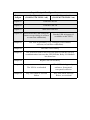
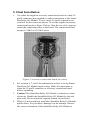
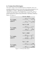
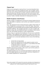
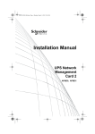
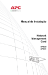
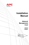
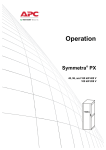
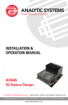
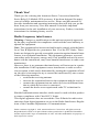
Thank You!
Thank you for selecting this American Power Conversion SmartSlot
Series Relay I/O Module UPS accessory. It has been designed for many
years of reliable, maintenance-free service. Please read this manual! It
provides installation and operating instructions that will help you get the
most from your accessory. Save this manual! It includes important
instructions for the safe installation of your accessory. Further, it includes
instructions for obtaining factory service.
Radio frequency interference
Warning: Changes or modifications to this unit not expressly approved
by the party responsible for compliance could void the users authority to
operate the equipment.
Note: This equipment has been tested and found to comply with the limits
for a Class B digital device, pursuant to Part 15 of the FCC Rules. These
limits are designed to provide reasonable protection against harmful interference in a residential installation. This equipment generates, uses and
can radiate radio frequency energy and, if not installed and used in accordance with the instructions, may cause harmful interference to radio communications.
However, there is no guarantee that interference will not occur in a particular installation. If this equipment causes interference to radio or television reception, which can be determined by turning the equipment off and
on, the user is encouraged to try to correct the interference by one or more
of the following measures:
• reorient the receiving antenna
• increase the separation between the equipment and the receiver
• connect the equipment into an outlet on a circuit different from
that to which the receiver is connected
• consult the dealer or an experienced radio/TV technician for
help.
Shielded communications interface cables must be used with this product
to ensure compliance with Class B FCC limits.
This digital apparatus does not exceed the Class B limits for radio noise
emissions from digital apparatus set out in the Radio Interference Regulations of the Canadian Department of Communications.
Entire contents copyright © 1995 American Power Conversion. All rights reserved.
Reproduction in whole or in part without written permission is prohibited. SmartSlot
and the stylized APC logo are trademarks of APC. All other trademarks are property of
their respective owners.
Contents
1
Introduction . . . . . . . . . . . . . . . . . . . . . . . . . . . . . . . . . . . . . . . . . 1
2
Configuration . . . . . . . . . . . . . . . . . . . . . . . . . . . . . . . . . . . . . . . . 2
3
Operation Check . . . . . . . . . . . . . . . . . . . . . . . . . . . . . . . . . . . . . . 4
4
Operating Considerations . . . . . . . . . . . . . . . . . . . . . . . . . . . . . . . 5
5
Final Installation . . . . . . . . . . . . . . . . . . . . . . . . . . . . . . . . . . . . . . 6
6
Connection Strategies . . . . . . . . . . . . . . . . . . . . . . . . . . . . . . . . . . 8
7
Dry Contact I/O Pinout. . . . . . . . . . . . . . . . . . . . . . . . . . . . . . . . . 9
8
Accessory Connection Board . . . . . . . . . . . . . . . . . . . . . . . . . . . 10
9
Troubleshooting . . . . . . . . . . . . . . . . . . . . . . . . . . . . . . . . . . . . . 11
10 Service . . . . . . . . . . . . . . . . . . . . . . . . . . . . . . . . . . . . . . . . . . . . 12
11 Specifications . . . . . . . . . . . . . . . . . . . . . . . . . . . . . . . . . . . . . . . 13
12 Declaration of Conformity . . . . . . . . . . . . . . . . . . . . . . . . . . . . . 14
1. Introduction
The APC SmartSlot Relay I/O Module is a SmartSlot Series UPS
accessory that provides the following features:
• UPS status information presented as six form C contact closures
• UPS control and testing by contact closure inputs
• Screw terminal connectors for easy integration into various
management systems.
Description
The SmartSlot Relay I/O Module consists of a printed circuit board
assembly (right below), and an accessory connection board (left
below). The SmartSlot Relay I/O Module installs in the SmartSlot of
the host device. The connector board, which has the screw terminals
for making connections to the SmartSlot Relay I/O Module, attaches
to the installed I/O module (see section 5).
3
Configuration
Switch
Figure 1, SmartSlot Relay I/O Module
Note the location of the configuration switches on the printed circuit
board in figure 1 above.
2. Configuration
Switch setting
The SmartSlot Relay I/O Module requires configuration before testing, final installation, and use. Note: While the SmartSlot Relay I/O
Module has a four position DIP configuration switch (marked CONFIG SWITCH on the printed circuit board— see figure 1), only position 1 is used. The other switches must be left in the off position.
Move the switch up for ON and down for OFF.
Configuration 1 is intended for use with UPSs that do not include a
bypass feature (like Smart-UPS). Configuration 2 is intended for use
with UPSs that include a bypass feature (like Matrix-UPS).
Choose from configuration 1 and configuration 2 in the table below.
Set CONFIG SWITCH position 1 as required.
Input/Output Configurations
Input/
Output
Configuration 1
(CONFIG SWITCH 1 off)
Configuration 2
(CONFIG SWITCH 1 on)
Input #1
Turn the UPS on
Input #2
Turn the UPS off
Input #3
Start UPS self-test
Input #4
Shut down the UPS (when onbatter except during a self-test
or run time calibration)
Put the UPS in bypass (if
available on the UPS)
Output #1
The UPS is on-battery (e.g., during a power failure,
self-test, or run time calibration)
Output #2
UPS has a low battery
Output #3
The protected load is not receiving power from the UPS or
communication between the UPS and the Relay I/O Module
has been lost
Output #4
Replace the UPS battery
Output #5
Output #6
The UPS is overloaded
The UPS is in bypass by
software, front panel,
rear panel selection
Any UPS fault or self-test
failure
Any UPS fault, self-test
failure, or overload
3. Operation Check
Check the operation of the SmartSlot Relay I/O Module before final
installation. Note: The UPS will not protect the load during this procedure.
1. Check the output relays by temporarily installing the SmartSlot
Relay I/O Module into the SmartSlot. See section 4 for information on installing the SmartSlot Relay I/O Module in the SmartSlot. Attach the supplied screw terminal connection board.
2.
Turn on the UPS. Wait for a few seconds for the SmartSlot Relay
I/O Module to initialize. Use a digital multimeter or continuity
checker to confirm that all N. O. (normally open) output contacts
are open and that all N. C. (normally closed) contacts are shorted.
Measure resistance from each common contact to the corresponding N. O. and N. C. contacts. Short circuit resistance should be
near 0 Ohms, while open circuit resistance should be greater than
1 megaohm.
3.
Remove the SmartSlot Relay I/O Module from the SmartSlot and
confirm that all outputs have changed states—that all N.O. contacts are shorted and that all N. C. contacts are open with respect
to their common contacts.
4.
Turn the UPS off. Check the inputs by temporarily installing the
SmartSlot Relay I/O Module into the SmartSlot. Attach the supplied screw terminal connection board.
5.
Short circuit input #1 to one of the ground contacts on the screw
terminal connection board. Confirm that the UPS turns on. Note:
Valid SmartSlot Relay I/O Module inputs require continuous
assertion for at least one second.
6.
Short circuit input #2 to ground. Confirm that the UPS turns off.
7.
Turn the UPS on and wait for the self-test to complete. Short circuit input #3 to ground. Confirm that the UPS performs a self-test.
8.
Disconnect the UPS from the AC power source. Short circuit
input #4 to ground. Confirm that the UPS enters sleep mode (this
requires from 20 to 600 seconds, depending on internal UPS settings). Reconnect the AC power source to the UPS.
4. Operating Considerations
Note: While the SmartSlot Relay I/O Module output contacts are voltage free, connected equipment may present hazardous voltages. Use
care during installation.
Please note the following SmartSlot Relay I/O Module characteristics
when making system integration decisions:
• The coils for all output relays are normally energized. This
means that the SmartSlot Relay I/O Module will generate all
possible alarms in case of a system fault, such as cable failure, SmartSlot Relay I/O Module removal, severe UPS battery discharge, or catastrophic hardware failure on the
module.
• All output contacts are isolated from each other and from
UPS system ground. Note: The outputs are not intended to
directly switch AC loads. See table below.
• Control inputs are designed to be driven by dry contact outputs. The contact closure sensing voltage available on these
inputs is nominally 5 Vdc at less than 1 mA. All control
inputs are referenced to UPS system ground.
• In order to properly de-bounce noisy contact closures, all
control inputs must be stable for at least one second to be
considered valid.
• Joint assertion of input #1 (turn the UPS on) and input #2
(turn the UPS off) will be ignored.
• Although control inputs are acted on as soon as possible,
there are several UPS conditions such as self-test or run time
calibration that can cause an input to be ineffective. For confirmation of inputs, observe changes in the corresponding
output(s).
Output Contact Ratings
Parameter
Value
Nominal switching capacity
1 A at 30 Vdc
Maximum switching power
30 W
Maximum switching voltage
60 Vdc
Maximum switching current
2 Adc
Maximum carrying current
2 Adc
Surge ratings
2 kV per Bellcore
TA-NWT-001089
1.5 kV per FCC part 68
5. Final Installation
1.
Use either the supplied accessory connection board or a male 25
pin D connector (not supplied) to make connections to the SmartSlot Relay I/O Module. To use a male 25 pin D connection see
section 6 for the connector pinout. To use the supplied accessory
connection board see figure 2 below. Note the use of tie wraps to
secure the connecting wires to the board. The connection board
accepts 16 AWG to 28 AWG wires.
Figure 2, accessory connection board wire dress
2.
3.
4.
See sections 6, 7, and 8 for information on how to set up SmartSlot Relay I/O Module input wiring. Make all connections to
either the 25 pin D connector or accessory connection board
before continuing.
Caution! The SmartSlot Relay I/O Module is sensitive to static
electricity. Handle the SmartSlot Relay I/O Module by the end
plate only. Do not touch the exposed printed circuit board.
While it is not possible to install the SmartSlot Relay I/O Module
upside down, it is possible to damage it in the attempt. Observe
the correct orientation of the SmartSlot Relay I/O Module as
shown in figure 3. Note that the sides of the printed circuit board
align with the locating slots in the sides of the SmartSlot. The
SmartSlot may be oriented horizontally or vertically in the host
device. The host device may be on or off.
5.
Use a #2 Phillips head screwdriver to remove the two screws
retaining the SmartSlot cover on the host device. Keep the screws
handy for step 7 below. Keep the SmartSlot cover for future use.
Figure 3, Relay I/O Module installation
6.
Orient the SmartSlot Relay I/O Module to fit in the SmartSlot as
shown. Slide the SmartSlot Relay I/O Module all the way into the
slot until the end plate is flush with the back panel of the host
device.
7.
Secure the SmartSlot Relay I/O Module with the screws removed
in step 5.
8.
Attach and secure either the accessory connection board or 25 pin
D connector as prepared in step 1.
6. Connection Strategies
The alarm outputs of the SmartSlot Relay I/O Module can be connected in a number of ways to meet the needs of the management system. Both N. O. or N. C. systems are accommodated in any
combination of AND or OR configurations. It is possible, then, to
combine SmartSlot Relay I/O Module alarm outputs to form compound outputs like replace battery OR fault, or on-battery AND low
battery. See figure 4.
Figure 4, AND and OR alarms
7. Dry Contact I/O Pinout
13 12 11 10
9
8
7
6
5
4
3
2
1
25 24 23 22 21 20 19 18 17 16 15 14
Function
Pin
Function
Pin
N. O. output #1
(NO1)
1
N. O. output #2
(NO2)
14
Output #1 common
2
Output #2 common
15
N. C. output #1
(NC1)
3
N. C. output #2
(NC2)
16
N. O. output #3
(NO3)
4
N. O. output #4
(NO4)
17
Output #3 common
5
Output #4 common
18
N. C. output #3
(NC3)
6
N. C. output #4
(NC4)
19
N. O. output #5
(NO5)
7
N. O. output #6
(NO6)
20
Output #5 common
8
Output #6 common
21
N. C. output #5
(NC5)
9
N. C. output #6
(NC6)
22
Control input #4
10
Ground
23
Control input #3
11
Ground
24
Control input #2
12
Ground
25
Control input #1
13
Ground
Shell
8. Accessory Connection Board
9.Troubleshooting
Problem
Possible Cause
Solution
The SmartSlot relay I/O
Module does not
respond to control
inputs.
Insufficient setup or
hold times.
Configure controlling
equipment to provide at
least one second of
alarm hold. See
section 4.
Invalid or intermittent
alarms.
Poor contact at either
the dry contact I/O connector or the accessory
connection board.
Correct poor contact
conditions. Tighten all
connector screws.
Alarms always on or
will not come on.
Relay welded.
Return the SmartSlot
Relay I/O module for
service. See section 10.
The SmartSlot Relay
I/O Module has failed.
See section 10 for
customer service
information.
The SmartSlot Relay I/
O Module does not generate alarms.
Other accessories
attached to the computer interface port of
the UPS stop working.
10. Service
If the SmartSlot Relay I/O Module requires service:
1. Check the SmartSlot Relay I/O Module using the troubleshooting
chart in section 9 before calling for service.
2.
Note the model number of the SmartSlot Relay I/O Module, the
serial number, and the date purchased. See the back cover of this
manual for the correct telephone number and call customer service. A technician will ask you to describe the problem and help
solve it over the phone, if possible, or will give you an RMA#. If
customer service is not available in your area, call the dealer that
sold the SmartSlot Relay I/O Module. If the SmartSlot Relay I/O
Module is under warranty, repairs are free. If not, there will be a
charge for repair.
3.
Pack the SmartSlot Relay I/O Module in its original packaging, if
possible. Damage sustained in transit is not covered under warranty.
4.
Include a letter with your name, RMA#, address, copy of the sales
receipt, description of the trouble, your daytime phone number,
and a check (if necessary).
5.
Mark the RMA# on the outside of the package. The factory cannot accept any package without this marking.
6.
Return the SmartSlot Relay I/O Module by insured, prepaid carrier to the address given by the technician.
11. Specifications
Electrical
SmartSlot specification compatible
Operating voltage:
16–27 Vdc
Operating current draw:
70 mAdc
Physical
Size (H x W x D):
4 x 4 x 1.5 inches (10.2 x10.2 x 3.8 cm)
Weight:
0.3 lb. (140 gm)
Shipping weight:
0.7 lb. (320 gm)
Environmental
Operating elevation (storage): 0 to 3,000 m (0 to 15,000 m)
Operating temp. (storage):
0 to 40 °C (0 to 45 °C)
Approvals
EMC verification:
FCC Class B, DOC class B,
EN55022 Class B
Electromagnetic immunity:
EN50082-1 verified
12.Declaration of Conformity
Application of Council Directives: 89/336/EEC
Standards to Which Conformity is Declared: EN55022, EN50082-1
Manufacturer’s Name:
American Power Conversion
132 Fairgrounds Road
West Kingston, RI 02892 USA
Importer’s Name and Address:
Type of Equipment: SmartSlot Relay I/O Module
Model Number: AP9610
Serial Numbers: A95040000001–A961299999999
Year of Manufacture: 1995, 1996
I, the undersigned, hereby declare that the equipment specified above
conforms to the above directive(s).
Place: Billerica, MA USA
Date: 3/31/95
Joseph Pomata,
regulatory compliance engineer
Limited Warranty
American Power Conversion (APC) warrants its products to be free from defects in
materials and workmanship for a period of two years from the date of purchase. Its obligation under this warranty is limited to repairing or replacing, at its own sole option, any
such defective products. To obtain service under warranty you must obtain a Returned
Material Authorization (RMA) number from APC or an APC service center. Products
must be returned to APC or an APC service center with transportation charges prepaid
and must be accompanied by a brief description of the problem encountered and proof
of date and place of purchase. This warranty does not apply to equipment which has
been damaged by accident, negligence, or misapplication or has been altered or modified in any way. This warranty applies only to the original purchaser who must have
properly registered the product within 10 days of purchase.
EXCEPT AS PROVIDED HEREIN, AMERICAN POWER CONVERSION MAKES
NO WARRANTIES, EXPRESS OR IMPLIED, INCLUDING WARRANTIES OF
MERCHANTABILITY AND FITNESS FOR A PARTICULAR PURPOSE. Some
states do not permit limitation or exclusion of implied warranties; therefore, the aforesaid limitation(s) or exclusion(s) may not apply to the purchaser.
EXCEPT AS PROVIDED ABOVE, IN NO EVENT WILL APC BE LIABLE FOR
DIRECT, INDIRECT, SPECIAL, INCIDENTAL, OR CONSEQUENTIAL DAMAGES ARISING OUT OF THE USE OF THIS PRODUCT, EVEN IF ADVISED OF
THE POSSIBILITY OF SUCH DAMAGE. Specifically, APC is not liable for any
costs, such as lost profits or revenue, loss of equipment, loss of use of equipment, loss of
software, loss of data, costs of substitutes, claims by third parties, or otherwise.
Life support policy
As a general policy, American Power Conversion (APC) does not recommend the use of
any of its products in life support applications where failure or malfunction of the APC
product can be reasonably expected to cause failure of the life support device or to significantly affect its safety or effectiveness. APC does not recommend the use of any of
its products in direct patient care. APC will not knowingly sell its products for use in
such applications unless it receives in writing assurances satisfactory to APC that (a) the
risks of injury or damage have been minimized, (b) the customer assumes all such risks,
and (c) the liability of American Power Conversion is adequately protected under the
circumstances.
Examples of devices considered to be life support devices are neonatal oxygen analyzers, nerve stimulators (whether used for anesthesia, pain relief, or other purposes),
autotransfusion devices, blood pumps, defibrillators, arrhythmia detectors and alarms,
pacemakers, hemodialysis systems, peritoneal dialysis systems, neonatal ventilator
incubators, ventilators for both adults and infants, anesthesia ventilators, and infusion
pumps as well as any other devices designated as critical by the U.S. FDA.
Hospital grade wiring devices and leakage current may be ordered as options on many
APC UPS systems. APC does not claim that units with this modification are certified or
listed as Hospital Grade by APC or any other organization. Therefore these units do not
meet the requirements for use in direct patient care.