1
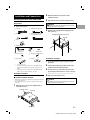
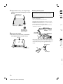
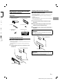
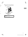
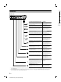
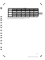
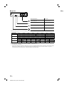
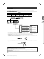
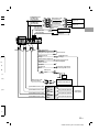
2
EN
SYSTEM INTEGRATION AUDIO PROCESSOR
PXA-H800
ES
• INSTALLATION
MANUAL
D’INSTALLATION
• MANUAL DE INSTALACIÓN
• GUIDE
ALPINE ELECTRONICS MARKETING, INC.
1-1-8 Nishi Gotanda,
Shinagawa-ku,
Tokyo 141-0031, Japan
Phone 03-5496-8231
ALPINE ELECTRONICS OF AMERICA, INC.
19145 Gramercy Place, Torrance,
California 90501, U.S.A.
Phone 1-800-ALPINE-1 (1-800-257-4631)
ALPINE ELECTRONICS OF CANADA, INC.
777 Supertest Road, Toronto,
Ontario M3J 2M9, Canada
Phone 1-800-ALPINE-1 (1-800-257-4631)
ALPINE ELECTRONICS OF AUSTRALIA PTY. LTD.
161-165 Princes Highway, Hallam
Victoria 3803, Australia
Phone 03-8787-1200
ALPINE ITALIA S.p.A.
Viale C. Colombo 8, 20090 Trezzano
Sul Naviglio (MI), Italy
Phone 02-484781
ALPINE ELECTRONICS GmbH
Wilhelm-Wagenfeld-Str. 1-3,
80807 München, Germany
Phone 089-32 42 640
ALPINE ELECTRONICS DE ESPAÑA, S.A.
Portal de Gamarra 36, Pabellón, 32
01013 Vitoria (Alava)-APDO 133, Spain
Phone 945-283588
ALPINE ELECTRONICS OF U.K. LTD.
Alpine House
Fletchamstead Highway,
Coventry CV4 9TW, U.K.
Phone 0870-33 33 763
ALPINE ELECTRONICS (BENELUX) GmbH
Leuvensesteenweg 510-B6,
1930 Zaventem, Belgium
Phone 02-725-13 15
ALPINE ELECTRONICS FRANCE S.A.R.L.
(RCS PONTOISE B 338 101 280)
98, Rue de la Belle Etoile, Z.I. Paris Nord Il,
B.P. 50016, 95945 Roissy Charles de Gaulle
Cedex, France
Phone 01-48638989
Qingdao Dongli Xinhaiyuan Printing Co., Ltd.
No.17, jiushuidong road, Qingdao, China
FR
Designed by ALPINE Japan
Printed in China (Y)
68-13530Z66-A
M3514448010
ALPINE PXA-H800_EN 68-13530Z66-A (B5)
ALPINE PXA-H800_EN 68-13530Z66-A (B5)
ENGLISH
Contents
WARNING
WARNING ............................................................ 2
CAUTION ............................................................. 2
PRECAUTIONS .................................................... 2
Installation and Connections
Mounting the Base Unit (PXA-H800) .................3
Preparation ...........................................................................3
Installation example 1 .........................................................3
Installation example 2 .........................................................3
Mounting the Microphone. ................................................4
Mounting the Commander Unit (RUX-C800)
(Sold separately) .................................................5
Preparation ...........................................................................5
Installing with Adhesive sheet............................................5
Installing with Commander unit holder...........................5
Connections ............................................................8
System Example ...................................................12
Connecting an automobile factory system (standard
audio, etc.) and External Amplifier ............................. 12
Connecting a Non Ai-NET AV Head Unit, External
Input and External Amplifier ....................................... 14
Connecting a Non Ai-NET Head Unit, External Input
and External Amplifier ................................................. 15
Connecting an Ai-NET compatible AV Head Unit
(INA-W910), ALPINE Navigation System, Ai-NET
compatible Changer and External Amplifier ............. 16
Connecting an Ai-NET compatible Head Unit, Ai-NET
compatible Changer and External Amplifier ............. 18
Confirmation ........................................................19
1-EN
ALPINE PXA-H800_EN 68-13530Z66-A (B5)
WARNING
WARNING
This symbol means important instructions. Failure to heed
them can result in serious injury or death.
DO NOT DISASSEMBLE OR ALTER.
Doing so may result in an accident, fire or electric shock.
KEEP SMALL OBJECTS SUCH AS BOLTS OR SCREWS OUT OF THE REACH
OF CHILDREN.
Swallowing them may result in serious injury. If swallowed, consult a physician
immediately.
USE THE CORRECT AMPERE RATING WHEN REPLACING FUSES.
Failure to do so may result in fire or electric shock.
BEFORE WIRING, DISCONNECT THE CABLE FROM THE NEGATIVE
BATTERY TERMINAL.
Failure to do so may result in electric shock or injury due to electrical shorts.
DO NOT SPLICE INTO ELECTRICAL CABLES.
Never cut away cable insulation to supply power to other equipment. Doing so
will exceed the current carrying capacity of the wire and result in fire or electric
shock.
DO NOT INSTALL IN LOCATIONS WHICH MIGHT HINDER VEHICLE
OPERATION, SUCH AS THE STEERING WHEEL OR SHIFT LEVER.
Doing so may obstruct forward vision or hamper movement etc. and results in
serious accident.
DO NOT DAMAGE PIPE OR WIRING WHEN DRILLING HOLES.
When drilling holes in the chassis for installation, take precautions so as not to
contact, damage or obstruct pipes, fuel lines, tanks or electrical wiring. Failure
to take such precautions may result in fire.
DO NOT USE BOLTS OR NUTS IN THE BRAKE OR STEERING SYSTEMS TO
MAKE GROUND CONNECTIONS.
Bolts or nuts used for the brake or steering systems (or any other safetyrelated system), or tanks should NEVER be used for installations or ground
connections. Using such parts could disable control of the vehicle and cause
fire etc.
DO NOT ALLOW CABLES TO BECOME ENTANGLED IN SURROUNDING
OBJECTS.
Arrange wiring and cables in compliance with the manual to prevent
obstructions when driving. Cables or wiring that obstruct or hang up on places
such as the steering wheel, shift lever, brake pedals, etc. can be extremely
hazardous.
MAKE THE CORRECT CONNECTIONS.
Failure to make the proper connections may result in fire or product damage.
DO NOT INSTALL THE MONITOR NEAR THE PASSENGER SEAT AIR BAG.
If the unit is not installed correctly the air bag may not function correctly and
when triggered the air bag may cause the monitor to spring upwards causing an
accident and injuries.
KEEP THE VOLUME AT A LEVEL WHERE YOU CAN STILL HEAR OUTSIDE
NOISES WHILE DRIVING.
Excessive volume levels that obscure sounds such as emergency vehicle sirens or
road warning signals (train crossings, etc.) can be dangerous and may result in
an accident. LISTENING AT LOUD VOLUME LEVELS IN A CAR MAY ALSO
CAUSE HEARING DAMAGE.
USE THIS PRODUCT FOR MOBILE 12V APPLICATIONS.
Use for other than its designed application may result in fire, electric shock or
other injury.
CAUTION
This symbol means important instructions. Failure to heed
them can result in injury or material property damage.
USE SPECIFIED ACCESSORY PARTS AND INSTALL THEM SECURELY.
Be sure to use only the specified accessory parts. Use of other than designated
parts may damage this unit internally or may not securely install the unit in
place. This may cause parts to become loose resulting in hazards or product
failure.
DO NOT INSTALL IN LOCATIONS WITH HIGH MOISTURE OR DUST.
Avoid installing the unit in locations with high incidence of moisture or dust.
Moisture or dust that penetrates into this unit may result in product failure.
HAVE THE WIRING AND INSTALLATION DONE BY EXPERTS.
The wiring and installation of this unit requires special technical skill and
experience. To ensure safety, always contact the dealer where you purchased this
product to have the work done.
ARRANGE THE WIRING SO IT IS NOT CRIMPED OR PINCHED BY A SHARP
METAL EDGE.
Route the cables and wiring away from moving parts (like the seat rails) or sharp
or pointed edges. This will prevent crimping and damage to the wiring.
PRECAUTIONS
• Be sure to disconnect the cable from the (–) battery post before installing
your PXA-H800. This will reduce any chance of damage to the unit in case of
a short-circuit.
• Be sure to connect the color coded leads according to the diagram. Incorrect
connections may cause the unit to malfunction or damage to the vehicle’s
electrical system.
• When making connections to the vehicle’s electrical system, be aware of the
factory installed components (e.g. on-board computer). Do not tap into these
leads to provide power for this unit. When connecting the PXA-H800 to the
fuse box, make sure the fuse for the intended circuit of the PXA-H800 has
the appropriate amperage. Failure to do so may result in damage to the unit
and/or the vehicle. When in doubt, consult your Alpine dealer.
• The PXA-H800 uses female RCA-type jacks for connection to other units (e.g.
amplifier) having RCA connectors. You may need an adaptor to connect other
units. If so, please contact your authorized Alpine dealer for assistance.
• Be sure to connect the speaker (–) leads to the speaker (–) terminal. Never
connect left and right channel speaker cables to each other or to the vehicle
body.
DO NOT BLOCK VENTS OR RADIATOR PANELS.
Doing so may cause heat to build up inside and may result in fire.
USE ONLY IN CARS WITH A 12 VOLT NEGATIVE GROUND.
(Check with your dealer if you are not sure.) Failure to do so may result in fire,
etc.
DO NOT OPERATE ANY FUNCTION THAT TAKES YOUR ATTENTION AWAY
FROM SAFELY DRIVING YOUR VEHICLE.
Any function that requires your prolonged attention should only be performed
after coming to a complete stop. Always stop the vehicle in a safe location before
performing these functions. Failure to do so may result in an accident.
IMPORTANT
Please record the serial number of your unit in the space provided below
and keep it as a permanent record. The serial number or the engraved
serial number is located on the bottom of the unit.
2-EN
ALPINE PXA-H800_EN 68-13530Z66-A (B5)
SERIAL NUMBER: __________________________________
INSTALLATION DATE: ______________________________
INSTALLATION TECHNICIAN: _______________________
PLACE OF PURCHASE:______________________________
Installation and Connections
2
Mounting the Base Unit (PXA-H800)
3
Preparation
1
Mark the installation screw positions at the
installation location.
Drill (3mm diameter max.) in the marked positions.
WARNING
When making holes, be careful not to damage pipes, tanks, electric wires,
etc. Doing so could lead to an accident or fire.
Check accessory parts.
A Power cable
B Ai-NET extension cable (5.5 m)
C USB cable (5 m)
4
D Speaker-RCA Conversion cable
(20 cm) (Red/White ×3 sets)
Install the device tightly with 4 self-tapping screws
(M4 × 14 mm) H.
Self-tapping screw (M4 × 14 mm) (×4)
Base Unit
E Bracket
(×4)
F Microphone (1 set)
<Microphone>
<Clip>
G Screw (M3 × 6 mm)
<Adhesive tape>
H Self-tapping screw (M4 × 14 mm)
(×4)
I Velcro fastener*1
(×4)
Installation example 2
J CD-ROM*2, *3
(×2)
(×2)
*1 Use when necessary.
*2 For details on how to install and use the CD-ROM, “Sound
Manager for PXA-H800,” refer to the Owner’s Manual – PC
guide.
*3 For details on how to install and use the CD-ROM, “SETUP
DISC,” refer to the Owner’s Manual – PC guide.
2
3
Cut out the external box paper template along the
perforation.
Temporarily hold the paper template in place at the
installation position with adhesive tape.
Put a bracket E in a predetermined position on the
paper template and mark where a screw is to be fixed.
For details on how to install the brackets, refer to step 5.
Installation example 1
e Set the installation location.
• Check that the provided cord is sufficiently long. Install the unit where
it is not exposed to water.
Do not install the unit or wiring where it interferes with driving or
an air bag.
1
1
4
Drill a hole (3mm diameter max.).
WARNING
When making holes, be careful not to damage pipes, tanks, electric wires,
etc. Doing so could lead to an accident or fire.
Affix the bracket E to the device tightly with the 4
screws (M3 × 6 mm) G.
Screw (M3 × 6 mm)
Base Unit
Bracket (×4)
3-EN
ALPINE PXA-H800_EN 68-13530Z66-A (B5)
5
Tightly install the bracket E at the designated paper
template position with the 4 self-tapping screws (M4 ×
14 mm) H.
Self-tapping screw
(M4 × 14 mm) (×4)
Mounting the Microphone.
When measuring ImprintEQ or AutoTCR before implementing
RoadEQ automated measurement, the installation position is different.
Before installing the microphone, make sure to refer to “Automatic
Measurement Function” in the Owner’s Manual – PC or Commander
guide.
For safe use, make sure of the following:
• location is stable and firm.
• driver’s view and operations are not obstructed.
Mou
C800
Prepa
1
Ch
A Com
• Mount the road noise measurement microphone on the sun
visor, dashboard or roof interior.
• Installation on the sun visor is the most common installation
position to measure road noise while driving.
Bracket (×4)
• Do not install the unit or wiring in a location that interferes
Paper template
with driving or an air bag.
Mount the brackets
symmetrically along
the paper template.
6
7
C Brac
Microphone
E Self(M4
Cable clamp
(Sold separately)
Remove the paper template.
Place the Base unit on the bracket E and install the
device tightly with the 4 screws (M3 x 6 mm) G.
Base Unit
Instal
• The mounting clip can be removed from the microphone base,
as in the illustration below. If you mount the microphone using
the base without the clip, use the supplied adhesive tape as
needed.
Microphone base
e Set
• Check
it is no
Do no
an air
1
Clip
Us
or
Screw (M3 × 6 mm)
Adhesive tape
C
4-EN
ALPINE PXA-H800_EN 68-13530Z66-A (B5)
erent.
c
der
Mounting the Commander Unit (RUXC800) (Sold separately)
Installing with Commander unit holder
e Set the installation location.
• Check that the provided cord is sufficiently long. Install the unit where
it is not exposed to water.
Do not install the unit or wiring where it interferes with driving or
an air bag.
• Console or dashboard, etc.
* Remove the components to which this product will be installed from
the automobile before installing.
Preparation
1
Check accessory parts.
A Commander cable (5 m)
B Commander unit holder
1
sun
ation
eres
C Bracket
2
D Screw (M3 × 6 mm)
3
(×2)
(×2)
E Self-tapping screw
(M4 × 14 mm)
Cut out the external box paper template along the
perforation.
Temporarily hold the paper template in place at the
installation position with adhesive tape.
Cut installation holes along the paper template with a
utility knife.
F Adhesive sheet (1 set)
(a)
WARNING
(b)
(×4)
(d)
When making holes, be careful not to damage pipes, tanks, electric wires,
etc.
Doing so could lead to accidents or fire.
(c)
Console or Dashboard etc.
Installing with Adhesive sheet
e base,
e using
as
e Set the installation location.
• Check that the provided cord is sufficiently long. Install the unit where
it is not exposed to water.
Do not install the unit or wiring where it interferes with driving or
an air bag.
1
Using the Adhesive sheet (a) F, install on the console
or dashboard.
Console or Dashboard etc.
Paper template
CAUTION
If the installation holes are too big, the Commander unit can rattle or come
off while driving. Make sure to use the paper template.
Adhesive sheet (a)
Commander Unit
Peel off
5-EN
ALPINE PXA-H800_EN 68-13530Z66-A (B5)
4
Bend the bracket C to follow the curvature of the
Commander unit holder B and the console or the
underside of the dashboard.
Screw holes
6
Tightly fix the Commander unit to the Commander
unit holder B with the provided 2 binding screws (M3
× 6 mm) D and apply Adhesive sheets (b) and (c) to
the predetermined unit holder mounting positions.
8
Aff
Ad
14
Screw holes
Bracket
Commander Unit
Adhesive sheet (b) (×2)
Bracket
Console or
Dashboard etc.
Commander unit holder
Adhesive sheet (c) (×2)
Screw (M3 × 6 mm) (×2)
Commander
unit holder
7
Install the Commander unit from step 6 above in the
installation position.
Console or Dashboard etc.
C
Make su
Comma
• To bend the bracket C, it is recommended to use a vise or pliers.
• Use the appropriate screw holes of the bracket according to the shape
of the vehicle installation position (i.e., console or dashboard).
5
Run the connector plug of the Commander cable
through the hole of the Commander unit holder B.
* With the plug claw facing up, run the plug though the hole
diagonally (as shown below).
Commander unit holder
Commander Unit
Connector plug
CAUTION
Doing so forcibly may break the plug.
6-EN
ALPINE PXA-H800_EN 68-13530Z66-A (B5)
er
ws (M3
) to
ons.
8
Affix the Commander unit holder B tightly using the 4
Adhesive sheets (d) F and 4 self-tapping screws (M4 ×
14 mm) E.
Self-tapping screw
(M4 × 14 mm) (×4)
2)
Bracket (×2)
Adhesive sheet
(d) (×4)
2)
the
Console or Dashboard
underside
c.
CAUTION
Make sure the Commander unit is tightly affixed. If any screws are loose, the
Commander unit can rattle or fall while driving.
7-EN
ALPINE PXA-H800_EN 68-13530Z66-A (B5)
*3 Th
Connections
e Left side
4
Blue/
White
Black
Cord colors and cord/terminal specifications
Connect to:
Remote On Lead (REM IN) *1
Connect to the head unit for RCA connections.
(Non Ai-NET connection)
Connect to the Remote On cord
of the head unit.
Ground Lead (GND)
Connect securely to a metal part of the vehicle’s
body.
Battery power Lead (BATT)
Power is supplied constantly to the PXA-H800
regardless of whether the engine key is on or off.
Yellow
Orange
Blue/
White
Illumination Lead (ILLM)
This lead may be connected to the vehicle’s
instrument cluster illumination lead. This will allow
the backlighting of the RUX-C800 (sold separately)
to dim whenever the vehicle’s lights are turned on.
• For de
Connect to the vehicle’s body.
Connect this lead to the
positive(+) post of the vehicle’s
battery.
To the instrument cluster
illuminationlead.
Use if the RUX-C800 (sold
separately) is connected.
Remote Out Lead (REM OUT)
Connect to the amplifier or other peripheral device. Connect to the Remote On Lead
of an amplifier.
Guide control Lead (GUIDE)
Used to interrupt the navigation system’s sound.
White/
Green
Navigation audio input connector (RCA input)
(NAVI)
Used to input the audio output signals of a
navigation system.
Changer input terminal (optical digital input)
Used when connecting an Optical Digital
compatible Changer, etc.
Head unit input terminal (optical digital input)
Used when connecting an Optical Digital
compatible Head Unit, etc.
Changer input terminal (Ai-NET input) *2
Used for system expansion (Ai-NET changer, etc.).
Head unit input terminal (Ai-NET input) *2
Used for system expansion (Head unit, etc.).
Microphone jack
Use when implementing an automatic
measurement of the automobile interior acoustics
(ImprintEQ/Auto TCR) or when implementing
an automatic adjustment of EQ characteristics
(RoadEQ) along with the quantity of road noise
while driving.
Audio input jacks (RCA inputs) *3
Used to input the audio output signals of a head
unit connected with RCA connections to the
PXA-H800.
Connect to the Guide Control
Lead of GUIDE SIGNAL I/F FOR
EXTERNAL NAVIGATION (KCE900E) (sold separately).
Connect to the Guide output
terminal of GUIDE SIGNAL I/F
FOR EXTERNAL NAVIGATION (KCE900E) (sold separately).
Connect to an Optical Digital
compatible product with a
optical fiber cable.
Connect to an Optical Digital
compatible product with a
optical fiber cable.
Connect to an Ai-NET product
using an Ai-NET cord.
For connection to the PXA-H800,
use the straight side.
Connect to an Ai-NET product
using an Ai-NET cord.
For connection to the PXA-H800,
use the straight side.
Connect to the microphone
(included)
Used for RCA connections.
Connect to the head unit.
*1 If connecting to a system without the Remote On cord (such as a factory system), connect to an incoming power supply cord (accessory power)
in the ACC position.
*2 With Ai-NET/RCA Interface cable (KCA-121B) (sold separately), a television or video player with RCA audio output can be input to the
device. For details, refer to “System Example” (page 10).
8-EN
ALPINE PXA-H800_EN 68-13530Z66-A (B5)
guide,
• If conn
• For de
*3 The allocation patterns for the device’s audio input (RCA input) are the following 3 patterns.
RCA Input
Pattern
AUX INPUT
CH-1 (L)
CH-2 (R)
CH-3 (L)
CH-4 (R)
CH-5 (L)
CH-6 (R)
RL
(Rear Left)
RR
(Rear Right)
C
(Center)
SubW
(Subwoofer)
RR
(Rear Right)
L
(Left)
R
(Right)
L
(Left)
AUX1
5.1ch Input
FL
(Front Left)
FR
(Front Right)
4ch&2ch Input
FL
(Front Left)
FR
(Front Right)
RL
(Rear Left)
2ch×3 Input
L
(Left)
R
(Right)
L
(Left)
AUX1
AUX2
AUX1
AUX2
R
(Right)
AUX3
R
(Right)
• For details on how to set the RCA input pattern, refer to “Setting the AUX Input System (AUX Input System Select)” in the Owner’s Manual – PC
n cord
ody.
guide, or “Setting the AUX Input System (AUX Input Setup)” in the Owner’s Manual – Commander guide.
• If connecting to an Ai-NET Head Unit/AV Head Unit, RCA input (AUX INPUT) connection is not available.
• For details on each “AUX INPUT” input pattern, refer to “System Example” (page 12).
icle’s
n Lead
trol
FOR
CE-
put
I/F
ON (KCE-
ital
a
ital
a
duct
-H800,
duct
-H800,
ne
power)
he
9-EN
ALPINE PXA-H800_EN 68-13530Z66-A (B5)
e Right side
e Sp
terminal specifications
Connect to:
Audio output jacks(RCA output) *
Outputs an audio signal
Connect to amplifier
RESET switch
The system of this unit is reset.
−
Commander connection terminal
Use when operating this unit from the RUX-C800
(sold separately).
Connect to the RUX-C800 (sold
separately).
Computer connection terminal (USB terminal)
Use when operating this unit via a computer.
Connect to a computer with the
USB cable accessory.
* The location of the connection to the external amp for the audio output terminal (RCA output) varies, as specified below, depending on the
connected speaker system.
Speaker System
F-2way+R+SW
(4.2ch system)
CH-1(L)
CH-2(R)
CH-3(L)
CH-5(L)
Front High(L)
Front High(R)
CH-6(R)
CH-7(L)
Rear
Front Low(L)*1
Front Low(R)*1
Rear(L)
Front High(L)
Front High(R)
Front Mid(L)*1
F-3way+R
(4.0ch system)
Front High(L)
Front High(R)
Front Mid(L)*1
Front Mid(R)*1
Rear(R)
Subwoofer(L)*2
Front Low(L)
Front Low(R)
Subwoofer(L)*2
Front Low(L)
Front Low(R)
Rear(L)
Front High(R)
Front Low(L)*1
Rear(R)
Center
Subwoofer
Center
Subwoofer
Rear
Front Low(R)*1
Subwoofer(R)*2
Rear
Front2Way
Front High(L)
Subwoofer(R)*2
Subwoofer
Front3Way
Front Mid(R)*1
CH-8(R)
Subwoofer
Front3Way
F-3way+SW
(2.2ch system)
F-2way+R+C+SW
(5.1ch system)
CH-4(R)
Front2Way
Rear(L)
Rear(R)
• For details on how to set the speaker system, refer to “Setting the Speaker System (Output System Select)” in the Owner’s Manual – PC guide, or
“Setting the Speaker System (System Select)” in the Owner’s Manual – Commander guide.
*1 An OFF setting is not available.
*2 If connecting 2 subwoofers, the subwoofer output can be set to stereo or monaural output. If connecting a subwoofer, set the subwoofer output
(Subwoofer 2) to “OFF.” For details, refer to “Setting the Speaker System (Output System Select)” in the Owner’s Manual – PC guide, or
“Setting the Speaker System (System Select)” in the Owner’s Manual – Commander guide.
10-EN
ALPINE PXA-H800_EN 68-13530Z66-A (B5)
e Speaker System Example
F-2way+R+SW(4.2ch System)
Front High(L)
Front High(R)
Front Low(L)
Front Low(R)
Rear(L)
F-3way+SW(2.2ch System)
Front High(L)
Front Mid(L)
Front High(R)
Front Mid(R)
Front Low(L)
Front Low(R)
Rear(R)
(sold
Subwoofer(L) Subwoofer(R)
Subwoofer(L) Subwoofer(R)
th the
F-3way+R(4.0ch System)
F-2way+R+C+SW(5.1ch System)
he
Center
8(R)
ofer(R)*2
ofer(R)*2
Front High(L)
Front High(R)
Front Mid(L)
Front Mid(R)
Front Low(L)
Front Low(R)
r(R)
oofer
Rear(L)
Rear(R)
Front High(L)
Front High(R)
Front Low(L)
Front Low(R)
Rear(L)
Rear(R)
oofer
e, or
Subwoofer
r output
or
11-EN
ALPINE PXA-H800_EN 68-13530Z66-A (B5)
System Example
Connecting an automobile factory system (standard audio, etc.) and External Amplifier
e Input Pattern: 4ch&2ch Input
AUX INPUT
CH-1 (L)
CH-2 (R)
CH-3 (L)
CH-4 (R)
CH-5 (L)
AUX1
FL
(Front Left)
FR
(Front Right)
CH-6 (R)
AUX2
RL
(Rear Left)
RR
(Rear Right)
L
(Left)
R
(Right)
*3
RUX-C800 (Sold separately)*1
Commander cable
(RUX-C800 included)
White
Computer connection
terminal
Audio output jacks
To External Amplifier
(see page 10)
External Amplifier
Rear speaker (L) output lead
Rear speaker (R) output lead
Front speaker (L) output lead
Front speaker (R) output lead
*5
Rear speaker (L)
Rear speaker (R)
Front speaker (L)
Front speaker (R)
*1 When using a factory car audio system, the RUX-C800 Commander (sold separately) is required.
*2 If your factory system does not have a Remote Turn-On Lead, connect a cable that enables an incoming power supply (accessory power) in
the ACC position.
*3 If using the Speaker-RCA Conversion cable, up to 6 channels can be input. Make connections according to your system.
*4 Before using the Speaker-RCA Conversion cable, remove the cord tip coating, cut the cord into 2 cables, connect the cable with commercially
available bullet or solderness terminals attached to the tips.
*5 When connecting a speaker input cable, connect via a solderless terminal or solderless connector after disconnecting the automobile’s speaker
cable.
Automobile speaker cable
CAUTION
Make sure to disconnect the factory speakers and the speaker output cable for the factory system.
When using fiber cable, follow the guidelines below:
• When laying or bundling optic fiber cables, the minimum bending radius should be 30 mm. Bending beyond the radius will break the cable, resulting in no
digital sound being output.
• Do not put the product or other items on the optic fiber cable.
12-EN
ALPINE PXA-H800_EN 68-13530Z66-A (B5)
Ai-NET/RCA Interface
cable KCA-121B
(Sold separately)
Ai-NET/RCA Interface
cable KCA-121B
(Sold separately)
White White
Red Red
White White
Red Red
RCA extension cable
(Sold separately)
RCA extension cable
(Sold separately)
To Digital Output
Terminal
Fiber optic cable
(Sold separately)
To Digital Output
Terminal
Fiber optic cable
(Sold separately)
White
Red
TV Tuner or Video
Player, etc.
White
TV Tuner or Video
Player, etc.
Red
Optical Digital Compatible
DVD Player, etc.
Optical Digital Compatible
DVD Player, etc.
*3
White
Red
Red
*5
L)
R)
(L)
Red
White
White
Guide Control Lead
White/Green
Navigation audio input connector
Not Connected
Illumination Lead
Orange
Illumination Lead
(Orange)
Remote Control Output Lead
Blue/White
To Remote On Lead of an
External Amplifier
Remote On Lead
Blue/White
*2
Ground Lead
Black
(R)
Connect to a metal part of
chassis body with a screw.
Battery Lead
Yellow
Fuse 10A
er) in
12V
ercially
RCA extension cable
(Sold separately)
White
TV Tuner or Video Player, etc.
Red
Black/White
Black
Black/White
Black
Black/White
Black
Speaker-RCA Conversion cable
speaker
Speaker-RCA Conversion cable
Speaker-RCA Conversion cable
Black/White
Black
Speaker-RCA Conversion cable
*4
Rear speaker (L) output lead
Rear speaker (R) output lead
Front speaker (L) output lead
Standard Car
Audio System
Front speaker (R) output lead
*5
n no
13-EN
ALPINE PXA-H800_EN 68-13530Z66-A (B5)
Connecting a Non Ai-NET AV Head Unit, External Input and External Amplifier
Conn
e Input Pattern : 5.1ch Input
e Inp
AUX INPUT
CH-1 (L)
CH-2 (R)
CH-3 (L)
CH-4 (R)
CH-5 (L)
CH-6 (R)
CH
RR
(Rear Right)
C
(Center)
SubW
(Subwoofer)
L
AUX1
FL
(Front Left)
FR
(Front Right)
RL
(Rear Left)
Ai-NET/RCA Interface
cable KCA-121B
(Sold separately)
Ai-NET/RCA Interface
cable KCA-121B
(Sold separately)
White White
Red Red
White White
RCA extension cable
(Sold separately)
RCA extension cable
(Sold separately)
Red Red
To Digital Output
Terminal
Fiber optic cable
(Sold separately)
To Digital Output
Terminal
Fiber optic cable
(Sold separately)
Computer
connection
terminal
White Red
Guide Control Lead
White/Green
Navigation audio input connector
Red White
Remote Control Output Lead
Blue/White
Ground Lead
Black
Battery Lead
Yellow
Fuse 10A
White
Red
TV Tuner or Video
Player, etc.
White
TV Tuner or Video
Player, etc.
Red
Optical Digital Compatible
DVD Player, etc.
Optical Digital Compatible
DVD Player, etc.
Audio output jacks
To External Amplifier (see page 10)
White
Commander cable
(RUX-C800 included)
RUX-C800 (Sold separately)
Not Connected
To Remote On Lead of an
External Amplifier
Connect to a metal part of
chassis body with a screw.
12V
Illumination Lead
Orange
Illumination Lead
Orange
Remote On Lead
Blue/White
RCA extension cable (Sold separately)
Remote On Lead
Blue/White
Center Speaker Output
RCA extension cable (Sold separately)
Subwoofer Output
RCA extension cable (Sold separately) White
Non Ai-NET AV Head
Unit (Sold separately)
Rear Output *2
Red
RCA extension cable (Sold separately)
Red
Front Output *2
White
*1 When using a head unit that is not Ai-NET compatible, the RUX-C800 Commander (sold separately) is required.
CAUTION
When using fiber cable, follow the guidelines below:
• When laying or bundling optic fiber cables, the minimum bending radius should be 30 mm. Bending beyond the radius will break the cable, resulting in no
digital sound being output.
• Do not put the product or other items on the optic fiber cable.
14-EN
ALPINE PXA-H800_EN 68-13530Z66-A (B5)
*1
*2
C
When u
• When
digita
• Do no
Connecting a Non Ai-NET Head Unit, External Input and External Amplifier
e Input Pattern : 2ch×3 Input
AUX INPUT
CH-1 (L)
CH-2 (R)
CH-3 (L)
AUX1
L (Left)
CH-4 (R)
CH-5 (L)
AUX2
R (Right)
L (Left)
R (Right)
Ai-NET/RCA Interface
cable KCA-121B
(Sold separately)
deo
White
Red
Ai-NET/RCA Interface
cable KCA-121B
(Sold separately)
White
Red
deo
L (Left)
White
RCA extension cable
(Sold separately)
Red
RCA extension cable
(Sold separately)
TV Tuner or Video
Player, etc.
White
TV Tuner or Video
Player, etc.
Red
To Digital Output
Terminal
Optical Digital Compatible
DVD Player, etc.
To Digital Output
Terminal
Computer
connection
terminal
White Red
Guide Control Lead
White/Green
Navigation audio input connector
Red White
White
Red
White
Fiber optic cable
(Sold separately)*2
Red White
R (Right)
Red
Fiber optic cable
(Sold separately)*2
rately)
CH-6 (R)
AUX3
Remote Control Output Lead
Blue/White
Ground Lead
Black
Battery Lead
Optical Digital Compatible
DVD Player, etc.
Audio output jacks
To External Amplifier
(see page 10)
Commander cable
(RUX-C800 included)
*1
RUX-C800 (Sold separately)
Not Connected
To Remote On Lead of an
External Amplifier
Connect to a metal part of
chassis body with a screw.
Yellow
Fuse 10A
12V
RCA extension cable
(Sold separately)
Illumination Lead
Orange
Remote On Lead
Blue/White
White
White
Red
Head
rately)
White
Red
Red
Red
Red
Red
White
TV Tuner or Video
Player, etc.
Non Ai-NET Head Unit
(Sold separately)
White
RCA extension cable (Sold separately)
RCA extension cable (Sold separately)
Illumination Lead
Orange
Remote On Lead
Blue/White
TV Tuner or Video
Player, etc.
White
*1 When using a head unit that is not Ai-NET compatible, the RUX-C800 Commander (sold separately) is required.
*2 Use when connected with an Optical Digital compatible Unit.
CAUTION
n no
When using fiber cable, follow the guidelines below:
• When laying or bundling optic fiber cables, the minimum bending radius should be 30 mm. Bending beyond the radius will break the cable, resulting in no
digital sound being output.
• Do not put the product or other items on the optic fiber cable.
15-EN
ALPINE PXA-H800_EN 68-13530Z66-A (B5)
Connecting an Ai-NET compatible AV Head Unit (INA-W910), ALPINE Navigation System, Ai-NET
compatible Changer and External Amplifier
Ai-NET extension cable (Changer included)
To Ai-NET Output
Terminal
Fiber optic cable (Sold separately) *2
To Digital Output
Terminal (Optical)
Ai-NET compatible
Changer *4, *5
To Remote
Control Eye Jack
Audio output jacks
Computer
connection
terminal
Not Used
To External Amplifier
(see page 10)
Commander cable
(RUX-C800 included)
Remote On Lead
Blue/White
Guide Control Lead
White/Green
Navigation audio
input connector
Remote Control
Output Lead
Blue/White
Remote Control
Eye (DVD Changer
included) *6
RUX-C800 (Sold separately)
Not Connected
KCE-900E (Sold
Guide Control separately)
Lead
White/Green Guide
RGB Cable
Signal I/F
RCA extension cable for External
To RGB
(Sold separately)
Navigation
Output
To GUIDE Output
Terminal
Terminal
To RGB
Output
To Remote On Lead of
Terminal
an External Amplifier
Ground Lead
Black
Connect to a metal
part of chassis body
with a screw.
Battery Lead
Yellow
Fuse 10A
ALPINE
Navigation
System (Sold
separately)
To RGB Input Terminal
(KCE-900E included)
12V
Illumination
Lead*1
Orange
Illumination Lead*1
Orange
Fiber optic cable (Sold separately)
To Digital
Output Terminal
(Optical)
Ai-NET extension cable*7
*1
*2
*3
*4
*5
*6
*7
To RGB Input Terminal
Ai-NET compatible
AV Head Unit
(INA-W910) (Sold
separately) *3
To Ai-NET Output
Terminal
Use when connected with the RUX-C800 Commander (sold separately).
Use when connected with an Optical Digital compatible Changer.
Set the system switch to [EQ/DIV] or [EXT AP]. For details, refer to the Owner’s Manual for the product connected.
Setting the system switch is required. For details, refer to the Owner’s Manual for the connected changer.
If the Ai-NET compatible Changer is a DVD Changer (DHA-S690 Series or DHA-S680 Series), do not connect its Switched Power Lead
(Red).
If the Ai-NET compatible Changer is a DVD Changer (DHA-S690 Series or DHA-S680 Series), do not connect the Remote Control Eye in
a system that uses an Ai-NET compatible AV Head Unit. (Connection of the remote input cord (white/brown) is required.) Use the Remote
Control Eye in a system that uses any other manufacturer’s monitor. For details, refer to the connected DVD changer’s instruction manual.
If connecting DVA-5210, connect it between the unit and the head unit using an additional Ai-NET extension cable. In this case, also
connect the audio output jacks (L=white/R=red) of DVA-5210 to the AUX INPUT CH-1 (L)/CH-2 (R) jacks of the unit.
16-EN
ALPINE PXA-H800_EN 68-13530Z66-A (B5)
C
When u
• When
digita
• Do no
NET
CAUTION
tput
When using fiber cable, follow the guidelines below:
• When laying or bundling optic fiber cables, the minimum bending radius should be 30 mm. Bending beyond the radius will break the cable, resulting in no
digital sound being output.
• Do not put the product or other items on the optic fiber cable.
te
ye Jack
ntrol
hanger
6
arately)
tion
(Sold
tely)
ad
ye in
emote
nual.
17-EN
ALPINE PXA-H800_EN 68-13530Z66-A (B5)
Connecting an Ai-NET compatible Head Unit, Ai-NET compatible Changer and External Amplifier
Conf
Ai-NET extension cable (Changer included)
To Ai-NET Output
Terminal
Fiber optic cable (Sold separately) *2
To Digital Output
Terminal (Optical)
Ai-NET compatible
Changer *4, *5
1
Se
Ma
sea
pro
2
3
Co
Tu
co
Ch
we
4
Computer
connection
terminal
Not Used
Audio output jacks
To External Amplifier
(see page 10)
Commander cable
(RUX-C800 included)
Guide Control Lead
White/Green
Remote On Lead
Blue/White
RUX-C800 (Sold separately)
Not Connected
Navigation audio input connector
Remote Control Output Lead
Blue/White
Illumination Lead*1
Orange
Ground Lead
Black
To Remote On Lead of an
External Amplifier
Illumination Lead*1
Orange
Connect to a metal part of
chassis body with a screw.
Ai-NET compatible
Head Unit (Sold
separately)*3
Battery Lead
Yellow
Fuse 10A
12V
Ai-NET extension cable*6
*1
*2
*3
*4
*5
*6
To Ai-NET Output
Terminal
Use when connected with the RUX-C800 Commander (sold separately).
Use when connected with an Optical Digital compatible Changer.
Checking and setting of the system switch are required. For details, refer to the Owner’s Manual for the product connected.
If connecting with an Optical Digital compatible Changer, setting the system switch is required. For details, refer to the Owner’s Manual for
the connected changer.
If the Ai-NET compatible Changer is a DVD Changer (DHA-S690 Series or DHA-S680 Series), do not connect its Switched Power Lead
(Red).
If connecting DVA-5210, connect it between the unit and the head unit using an additional Ai-NET extension cable. In this case, also
connect the audio output jacks (L=white/R=red) of DVA-5210 to the AUX INPUT CH-1 (L)/CH-2 (R) jacks of the unit.
CAUTION
When using fiber cable, follow the guidelines below:
• When laying or bundling optic fiber cables, the minimum bending radius should be 30 mm. Bending beyond the radius will break the cable, resulting in no
digital sound being output.
• Do not put the product or other items on the optic fiber cable.
18-EN
ALPINE PXA-H800_EN 68-13530Z66-A (B5)
Ma
lam
ifier
tput
Confirmation
1
Securing leads, etc.
Make sure leads are not pinched by moving such as the
seat rail, etc. Also check for damaged from sharp edges or
protrusion.
2
3
Connect the battery (−) terminal.
Turn on the engine key. Make sure the unit operating
correctly by referring to the Owner’s Manual.
Check the Owner’s Manuals for the connected products as
well.
4
Make sure all factory components such the brake
lamps, etc. work correctly.
arately)
ble
Output
ual for
ad
n no
19-EN
ALPINE PXA-H800_EN 68-13530Z66-A (B5)


![2 Gire el [Codificador giratorio] para seleccionar](http://vs1.manualzilla.com/store/data/006238366_1-359311a6108ed310ba7d779d3b792145-150x150.png)