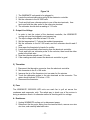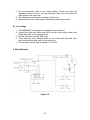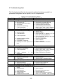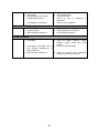
1
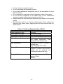
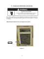
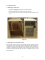
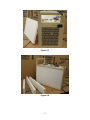
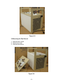
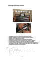
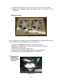
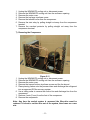
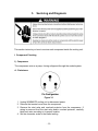
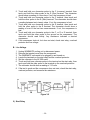
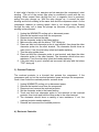
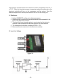
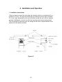
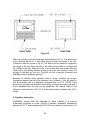
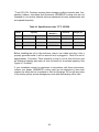
WINEMATE Cooling Unit
Service Manual
WM3500HZD
WM4500HZD
WM6500HZD
WM8500HZD
Vinotemp International Inc.
www.vinotemp.com
SAFETY INFORMATION
-1-
TABLE OF CONTENTS
1.
Introduction………………………………………………..3
I. Goals and Objectives…………………….…...……………………………3
II. R134a Refrigerant Service Information.....................…………..…….3
2.
Component Information and Access………………….5
I. Model and Serial Label Location…………………………………………5
II. Component Access…………………………………………………………6
1) Removing the Outer Cover…………………………..……………...…..6
2) Removing the Inner Styrofoam Cover…..……………………………..6
3) Removing the Fan Shroud…………………..…………………………..8
4) Removing the Electronic Controller……………..……………………..9
5) Removing the Thermistor………………………………………………..9
6) Removing Fan Motors…………………………………………………...10
7) Removing the Start Relay and Overload Protector …………….....10
8) Removing the Compressor……..………………………………………11
9) Removing the Condenser……..………………………………………..12
10) Removing the Evaporator…..…………………………………………..12
3.
Servicing and Diagnosis……………………………….13
I. Identifying Component Problems........……….…….………………….13
1) Compressor……………………………………………………………….13
2) Start Relay…………………………………………………………………14
3) Overload Protector.………………………………………………………15
4) Electronic Controller……………………………………………………15
5) Thermistor..………………………………………………………………..17
6) Fan Motors.………………………………………………………………..17
II. Wiring Diagram.….……..…………………………………..……………..18
III. Troubleshooting Chart.…....…………….………………………………19
4.
Installation and Operation……………………………..21
I. Installation Instructions………..…………………………………………21
II. Operation Information.….………………………………………………..22
5.
Customer Support………………………………………24
6.
Warranty Information…………………………………..25
I. Limited Warranty …………………………………..……………………..25
II. Limitation of Implied Warranty.………………………………………….26
-2-
1. Introduction
VINOTEMP assumes no responsibility for any repairs made on
products by anyone other than authorized service technician
This manual has been prepared to provide the information on installing,
servicing, troubleshooting and repairing procedures for the WINEMATE
3500HZD, 4500HZD, 6500HZD and 8500HZD cooling unit.
I. Goals and Objectives
The goal of this manual is to provide detailed information that will enable the
service personnel to properly install and repair the cooling unit, and troubleshoot
and diagnose malfunctions.
The objectives of this manual are that the service personnel will
• Fully understand the proper safety precautions
• Successfully install the cooling unit
• Successfully troubleshoot and diagnose malfunctions
• Successfully perform necessary repairs
• Successfully return the cooling unit to proper operational status
II. R134a Refrigerant Service Information
This cooling unit uses R134a refrigerant. This refrigerant requires synthetic ester
oil in the compressor. This cooling system does not tolerate contamination from
any of the following:
•
•
•
•
•
•
•
•
Other refrigerants
Moisture
Petroleum-based lubricants
Silicone lubricants
Cleaning components
Rust inhibitors
Leak detection dyes
Any other types of additive
As a result, the following precautions should be observed:
•
•
Use equipment dedicated to R134a sealed system only.
Use R134a refrigerant for back-flushing.
-3-
•
•
•
•
•
•
•
Use dry nitrogen to purge the system.
Do not overcharge the refrigeration system.
Do not leave replacement compressor open to the atmosphere for more
than 10 minutes.
Do not operate the compressor without refrigerant charge in the system.
Do not use the compressor if the rubber plugs on the replacement
compressor appear to have been tampered or removed.
Always replace the filter-drier when performing any repairs on the sealed
system.
The filter-drier must be cut from the sealed system. Never unbraze the
filter-drier from system tubing. Applying heat will drive moisture back into
sealed system.
Table 1-1 Health and Safety Handling of R134a
Allowable Overall Exposure Limit 1,000 ppm
Vapor Exposure to Skin
No Effect
Liquid Exposure to Skin
Can cause frostbite
Vapor Exposure to Eyes
Can cause very slight irritation
Liquid Exposure to Eyes
Can cause frostbite
Above Minimum Exposure Limit
Can cause asphyxiation, tachycardia
and cardiac arrhythmia's. Wear
appropriate skin and eye care.
Spill Management
Combustible sources. Evacuate or
ventilate area.
May decompose if in contact.
Fire and Explosion Hazards
Made with flames and heating
elements. Container may explode if
heated due to pressure rise.
Combustion products are toxic.
Storage Conditions
The procedures/rules for R12 also
apply to R134a.
Reclaim
-4-
2. Component Information and Access
This section provides you the component information and access inside the
cooling unit. The components and their locations are shown Figures 2-1 through
2-11 below.
I. Model Number & Serial Label and Component Locations
Label
Figure 2-1
-5-
II. Component Access
1) Removing the Outer Cover
1. Unplug the WINEMATE cooling unit or disconnect power.
2. Remove the WINEMATE cooling unit from the enclosure.
3. To remove the outer cover, remove all screws from each side and on the
top.
Figure 2-2
2) Removing the Inner Styrofoam Covers
Once the outer cover is removed, this will expose the inner styrofams. The top
large Styrofoam cover seals off the condenser and evaporator fan compartments.
To gain access to the other components, the styrofoam covers will need to be
removed. To separate the top styrofoam covers, a knife can be used to cut along
the seam and through the seal. Take care as not to damage any wiring or the
styrofoam pieces.
-6-
Figure 2-3
Figure 2-4
-7-
Figure 2-5
3) Removing the Fan Shroud
1. Remove the 4 rivets
2. Disconnect wires
3. Remove the shroud
Figure 2-6
-8-
4) Removing the Electronic Controller
Figure 2-7
Figure 2-8
1.
2.
3.
4.
5.
6.
7.
Unplug the WINEMATE cooling unit or disconnect power.
Remove WINEMATE cooling unit from the enclosure opening
Remove the top large styrofoam cover.
Disconnect all three connectors for the electronic controller.
Unsnap the thin plastic cover off the front of the electronic controller.
Remove the two screws from the front of the electronic controller.
Locate the retainer just inside the front panel going around the outside of
the electronic controller. While squeezing both tabs of the retainer, push
the electronic controller out of the opening.
5) Removing the Thermistor
1.
2.
3.
4.
Unplug the WINEMATE cooling unit or disconnect power.
Remove the WINEMATE cooling unit from the enclosure opening.
Remover the outer cover.
Remove the top large styrofoam cover.
-9-
5. Disconnect the thermistor with connector from the electronic controller.
6. Remove the thermistor from the mounting clip on the front of the
evaporator.
6) Removing Fans
Figure 2-9
The 2 condenser and evaporator fans are attached to the horizontal fan shroud.
They are the same and all powered up at the same time.
1. Unplug the WINEMATE cooling unit or disconnect power.
2. Remove the WINEMATE cooling unit from the enclosure opening.
3. Remover the outer cover.
4. Remove the top large styrofoam cover.
5. Disconnect the two wires going to the electrical junction block.
6. Remove the four screws holding the fan to the shroud.
7) Removing the
Start Relay
and Overload
Protector
Figure 2-10
- 10 -
1.
2.
3.
4.
5.
6.
Unplug the WINEMATE cooling unit or disconnect power.
Remove the WINEMATE cooling unit from the enclosure opening.
Remover the outer cover.
Remove the top large styrofoam cover.
Remove the terminal cover from the compressor.
Remove the start relay by pulling straight out away from the compressor
terminal.
7. Remove the overload protector by pulling straight out away from the
compressor terminal.
7) Removing the Compressor
1.
2.
3.
4.
5.
6.
7.
8.
Figure 2-11
Unplug the WINEMATE cooling unit or disconnect power.
Remove the WINEMATE cooling unit from the enclosure opening.
Remover the outer cover.
Remove the top and bottom styrofoam covers and the fan shroud.
Place piercing valves onto the process tubes and discharge the refrigerant
into an approved R134a recovery system.
Use a tubing cutter to remove the suction line and discharge line from the
compressor.
Remove 4 nuts (11mm) from the feet of the compressor.
Remove the compressor
Note: Any time the sealed system is accessed the filter-drier must be
replaced. It is best to cut the drier out of the system, then braze on a new
one.
- 11 -
9) Removing the Condenser
1.
2.
3.
4.
5.
Unplug the WINEMATE cooling unit or disconnect power.
Remove the WINEMATE cooling unit from the enclosure opening.
Remover the outer cover.
Remove the top large styrofoam cover and the inner divider.
Place piercing valves onto the process tubes and discharge the refrigerant
into an approved R134a recovery system.
6. Use a tubing cutter to remove the hot gas line and liquid line from the
condenser.
7. Remove 4 rivets from the condenser.
8. Remove the condenser
10) Removing the Evaporator
1.
2.
3.
4.
5.
Unplug the WINEMATE cooling unit or disconnect power.
Remove the WINEMATE cooling unit from the enclosure opening.
Remover the outer cover.
Remove the top large styrofoam cover and the inner divider.
Place piercing valves onto the process tubes and discharge the refrigerant
into an approved R134a recovery system.
6. Cut the capillary line and suction line from the evaporator.
7. Remove 4 rivets from the evaporator.
8. Remove the evaporator.
- 12 -
3.
Servicing and Diagnosis
This section instructs you how to service each component inside the cooling unit.
I. Component Checking
1) Compressor
The compressor acts as a pump, forcing refrigerant through the sealed system.
A. Resistance
Figure 3-1
1. Unplug WINEMATE cooling unit or disconnect power.
2. Remove the terminal cover from the compressor.
3. Remove the start relay and overload protector from the compressor. If
wiring is removed from the start relay and/or overload protector, carefully
label each wire according to its proper location.
4. Set the ohmmeter scale to the lowest setting.
- 13 -
5. Touch and hold one ohmmeter probe to the C (common) terminal, then
touch and hold the other probe to the R (Run) terminal. The ohmmeter
should show a reading of a few ohms. If not, the compressor is bad.
6. Touch and hold one ohmmeter probe to the C terminal, then touch and
hold the other probe to the S (Start) terminal. The ohmmeter should show
a reading between ten to twenty ohms. If not, the compressor is bad.
7. Touch and hold one ohmmeter probe to the R terminal, then touch and
hold the other probe to the S terminal. The ohmmeter should show a
reading of sum of the last two measurements. If not, the compressor is
bad.
8. Touch and hold one ohmmeter probe to the C, or R or S terminal, then
touch and hold the other probe to the ground on the compressor. The
ohmmeter should read infinity. Any resistance indicates a shorted
compressor.
9. If the compressor tests ok, but does not start, check start relay, overload
protector and live voltage.
B. Live Voltage
1.
2.
3.
4.
5.
6.
Unplug WINEMATE cooling unit or disconnect power.
Remove the terminal cover from the compressor
The WINEMATE unit needs to be plugged in and turned on.
Locate the terminals on the start relay and the overload protector.
Set the voltmeter to the AC 200 scale.
Touch and hold one voltmeter probe to the terminal on the start relay, then
touch and hold the other probe to the terminal on the overload protector.
7. The voltmeter should show a reading of 115 volts.
8. If the test is good and the compressor does not start, check the start relay,
overload protector, and measure the resistance.
Figure 3-2
2) Start Relay
- 14 -
A start relay’s function is to energize and de-energize the compressor’s start
winding. The coil of the current type relay is connected in series with the run
winding. When current flows through the coil, a magnetic force is produced,
pulling the relay plunger up. With the relay plunger up, it connect the start
winding and the run winding at the same time and the compressor starts. As the
compressor reaches its running speed, there is not enough current flowing
through the relay coil to keep the plunger up (because of gravity), the start
winding is disconnected.
1.
2.
3.
4.
5.
6.
Unplug the WINEMATE cooling unit or disconnect power.
Remove the terminal cover from the compressor.
Disconnect and remove the relay.
Set the ohmmeter scale to the lowest setting.
Make sure the relay with the letters “TOP” facing up.
Place and hold one ohmmeter probe in one terminal, then place the other
ohmmeter probe into the other terminal. The ohmmeter should show an
open circuit. If not, the start relay is bad and needs replacing.
7. Turn the relay upside down.
8. Place and hold the ohmmeter probe in one terminal, and place the other
ohmmeter probe in the other terminal. The ohmmeter should show zero
resistance. If not, the start relay is bad and needs replacing.
9. If the start relay is good, reinstall and reconnect the relay with the letters
“TOP” facing up.
3) Overload Protector
The overload protector is a bi-metal that protects the compressor. If the
compressor gets too hot the overload protector opens and stops the compressor.
Once it has cooled the overload protector contacts close.
1.
2.
3.
4.
5.
Unplug WINEMATE cooling unit or disconnect power.
Remove the terminal cover from the compressor.
Disconnect and remove the overload protector
Set the ohmmeter scale to the lowest setting.
Touch and hold one ohmmeter probe to one terminal on the overload
protector, then touch and hold the other probe to the other terminal.
6. The ohmmeter should show a reading of zero resistance. If not, the
overload protector needs replacing.
7. Reinstall and reconnect the overload protector.
4) Electronic Controller
- 15 -
The electronic controller allows the customer to select a temperature form 45 °F
to 75 °F. When the thermistor senses a temperature above the setting value, the
electronic controller will turn on the compressor and fan motors. Once the
selected temperature is sensed, the electronic will turn off the cooling unit.
A. Resistance
1. Unplug WINEMATE cooling unit or disconnect power.
2. Disconnect the connector with the red and white wires connected to the
input of the electronic controller.
3. Touch and hold one ohmmeter probe to one terminal on the electronic
controller, then touch and hold the other probe to the other terminal.
4. The ohmmeter should show a reading of 825Ω ± 10%.
5. Reconnect the wire connector to the electronic controller.
B. Input Live Voltage
Figure 3-3
- 16 -
Figure 3-4
1.
2.
3.
4.
The WINEMATE unit needs to be plugged in.
Locate the red and white wires going to the electronic controller.
Set the voltmeter to the AC 200 scale.
Touch and hold one voltmeter probe to one of the wire terminals, then
touch and hold the other probe to the other wire terminal
5. The voltmeter should show a reading of 115 volts.
C. Output Live Voltage
1. In order to test the output of the electronic controller, the WINEMATE
cooling unit must be plugged in and powered up.
2. The input voltage must read at least 110 volts.
3. Set the temperature 5° F above the ambient temperature.
4. Set the voltmeter to the AC 200 scale, and the voltmeter should read 0
volts.
5. Now warm the thermistor by hands for a while.
6. Locate the red and black wires leaving from the electronic controller.
7. Touch and hold one voltmeter probe to the red wire, then touch the other
probe to the black wire.
8. Now the voltmeter should read 115 volts.
9. If the readings are both correct the electronic controller is good.
5) Thermistor
1.
2.
3.
4.
Disconnect the thermistor connector from the electronic controller.
Set ohmmeter to the R x 10K scale.
Immerse the tip of the thermistor into ice water for five minutes
Touch the ohmmeter probes to the wire terminals on the connector. The
meter should indicate 27.3 below ± 10%.
5. Reconnect the thermistor.
6) Fans
The WINEMATE 3500-8500 HZD units use each fan to pull air across the
condenser and evaporator coils. The safest way to check one of the motors is
doing a resistance check. An alternate method is checking with live voltage.
A. Resistance
1. Unplug WINEMATE cooling unit or disconnect power.
2. Disconnect the fan motor wiring from the terminal block, remove one wire
at a time, and carefully label each wire.
- 17 -
3. Set the ohmmeter scale to the lowest setting. Touch and hold one
ohmmeter probe to one of the wire terminals, then touch and hold the
other probe to the other wire.
4. The ohmmeter should show a reading of tens ohms.
5. Reconnect the wires to the proper terminals as previously marked.
B. Live voltage
1. The WINEMATE unit needs to be plugged in and turned on.
2. Locate the black and white wires from the fan motor being tested and
follow them back to the terminal block.
3. Set the voltmeter to the AC 200 scale.
4. Touch and hold one voltmeter probe to one of the wire terminals, then
touch and hold the other probe to the other wire.
5. The voltmeter should show a reading of 115 volts.
II. Wiring Diagram
Figure 3-5
- 18 -
III. Troubleshooting Chart
This Troubleshooting Chart is not prepared to replace the training required for a
professional refrigeration service person, not is it comprehensive.
Complaint
1. Unit not running
a.
b.
c.
d.
e.
f.
Table 3-1 Troubleshooting Chart
Possible Causes
Response
Power cord unplugged
No power to unit.
Incorrect Temperature setting
Low voltage
Incorrect or loose wirings
Failed components.
a.
b.
c.
d.
e.
f.
Check for power cord plug
Check power at receptacle& fuses
Check for temperature setting
Contact an authorized electrician
Check all wirings and connections
Check start relay, start capacitor,
overload protector, compressor. Fans.
2. Compressor stopping and starting but short running time
a. Incorrect temperature setting
a. Set 55 to 60 °F
b. Incorrect voltage
c. Failed thermistor
d. Failed components
e.
f.
g.
h.
Improper condenser airflow
Dirty condenser
Overcharge of refrigerant
Discharge or suction pressure too
high
b. Check for voltage
c. Check thermistor by placing it in ice
water and measuring resistance
d. Check compressor windings, start relay
and overload protector.
e. Check for condenser fan
f. Clean condenser
g. Remove refrigerant
h. Refer to OEM service information
3. Fan motor running but compressor not running
a. Incorrect power supply
b. Incorrect or loose wirings
c. Failed components
d. Liquid
refrigerant
compressor
in
the
a. Check for proper voltage
b. Check all wirings and connections
c. Check start relay, start capacitor,
overload protector, compressor.
d. Refer to OEM service information.
4. Compressor running but fan not running
a. Fan blade bond
b. Incorrect or loose wirings
c. Failed motors
a. Check for proper clearance
b. Check all wirings
c. Check for open or shorted windings
5. No cooling but compressor and fan running
a. Evaporator airflow restriction
b. Refrigerant leakage
c. Refrigeration system restriction
a. Check for airflow through evaporator
b. Check for loss of refrigerant
c. Check for restrictions
6. Insufficient cooling or unit running too long
a. Improper evaporator or condenser
airflow
b. Dirty Condenser
c. Iced evaporator
d. Malfunctioning fans
e. Improper seals
f. Improper area to be cooled
- 19 -
a. Check for air restrictions
b.
c.
d.
e.
f.
Clean condenser
Defrost and reset temperature
Check for both fans
Check for gasket and door opening
Check for excessive load incorrect
g. Low voltage.
h. Operating 60 Hz unit at 50Hz
i. Sealed system problem
j.
Undercharge or overcharge
installation
g. Check power supply
h. Use proper 60 Hz
i. Check for loss of refrigerant
restrictions
j. Add or remove refrigerant
or
7. House circuit tripping
a. Incorrect fuse or breaker
b. Incorrect wirings
c. Malfunctioning components
a. Check for proper fuse or breaker
b. Check wirings and connections
c. Check failed components
8. Noisy operation
a. Mounting area not firm
b. Loose parts
c.
Compressor overloaded due to
high ambient temperatures or
airflow restriction
d. Malfunctioning components
- 20 -
a. Add support to improve installation
b. Check fan blades, bearings, cabinet
washers, tubing contact and loose
screws.
c. Check for airflow blockage
d. Check for internal loose, inadequate
lubrication and incorrect wirings
4. Installation and Operation
I. Installation Instructions
Select a place to mount the unit where the exhaust airflow is unobstructed for a
minimum of 6 inch. The area into which the unit exhausts must be well ventilated.
If it is not, heat exhausted by the unit will build up and the unit will not operate
properly. Additionally, cold air from the front opening must remain unobstructed.
The unit should be mounted near the ceiling and as close to equal distance from
each end of the wall as possible.
Figure 4-1
- 21 -
FRONT VIEW
REAR VIEW
Figure 4-2
Make an opening in the wine cellar wall as illustrated in Fig. 4-1. The dimensions
of the opening should be ¼ inch larger than the width and height of the unit.
Construct a shelf as shown in Fig.4-1. The shelf must be capable of supporting
the weight of the unit. Place the unit on the shelf with the back of unit flush with
the outside of the wall. Attach the grille to the outside wall with screws. Seal the
inside with a high quality weather stripping and cover with molding. Attach the
molding to the wall not the unit. Plug the unit into a properly grounded and
dedicated outlet of adequate capacity.
Because of potential safety hazards under a certain condition we strongly
recommend against the use of an extension cord. However, if you still select to
use an extension cord, it is absolutely necessary that it is a UL LISTED 3-wire
grounding type appliance extension cord having a 3-blade grounding plug and a
3-slot receptacle that will plug into the appliance. The marked rating of the
extension cord should be 115 V, 20 A. or equivalent and not greater than 15ft in
length.
II. Operation Information
WINEMATE cooling units are designed to, when installed in a properly
constructed enclosure or closet, provide a constant, selectable, temperature
between 52-62 °F while maintaining 55-70% RH at an ambient environment of 75
- 22 -
°F and 55% RH. Products requiring these storage conditions include wine, furs,
pastries, tobacco, chocolates and documents. WINEMATE cooling units are not
intended to cool service cabinets that are maintained at lower temperatures and
are opened frequently.
Table 4-1 Specification under 75 °F, 55%RH
Model
Capacity
Dimensions
(WxHxD")
Electrical
Weight (lb)
3000 bottles 14.25x19.75x21.25 115V 60Hz 6A
75
4500hzd Up to 1000 cu ft 4500 bottles 14.25x19.75x21.25 115V 60Hz 9A
75
3500hzd
Up to 650 cu ft
6500hzd Up to 1500 cu ft 6500 bottles
17x28x22
115V 60Hz 14A
110
8500hzd Up to 2000 cu ft 8500 bottles
17x28x22
115V 60Hz 16A
110
Before installing the unit in the enclosure, place it on a table and plug it into a
properly grounded outlet. it will run as soon as it is plugged in. Allow it to run for
approximately 15 minutes. There should be a flow of cool air from the front cold
air discharge opening and warm air from the back hot air exhaust opening. See
Figure 4-1 for detail.
If your installation cannot be performed in accordance with these instructions,
contact your dealer. WINEMATE cooling units are not designed to have duct
systems on either the hot air exhaust or cold air discharge. Do not drill any holes
in the cooling unit as severe damage may occur and the warranty will be void.
- 23 -
5. Customer Support
If you still have problems, please contact us at:
Vinotemp International
17631 South Susana Road
Rancho Dominguez, CA 90221
Tel: (310) 886-3332
Fax: (310) 886-3310
Email: [email protected]
- 24 -
6. Warranty
I. Limited Warranty
VINOTEMP warrants its products to be free from defects due to workmanship or
materials under normal use and service, for twelve months after the initial sale. If
the product is defective due to workmanship or materials, is removed within
twelve months of the initial sale and is returned to VINOTEMP, in the original
shipping carton, shipping prepaid, VINOTEMP will at its option, repair or replace
the product free of charge. Additionally VINOTEMP warrants all parts to be free
from defects for a period of sixty months after initial sale.
This warranty constitutes the entire warranty of the VINOTEMP with respect to its
products and is in lieu of all other warranties, express or implied, including any of
fitness for a particular purpose. In no event shall VINOTEMP be responsible for
any consequential damages what is so ever. Any modification or unauthorized
repair of VINOTEMP products shall void this warranty.
Service under Warranty
This service is provided to customers within the continental UNITED STATES
only. VINOTEMP cooling units are warranted to produce the stated number of
BTU/H. While every effort has been made to provide accurate guidelines,
VINOTEMP can not warranty its units to cool a particular enclosure.
In case of failure, VINOTEMP cooling units must be repaired by the factory or its
authorized agent. Repairs or modifications made by anyone else will void the
warranty.
Should a VINOTEMP cooling unit fail, contact the dealer for instructions. Do not
return the unit to the factory without authorization from VINOTEMP. If the unit
requires repair, re-pack it in the original shipping carton and return it to the
factory, shipping prepaid. VINOTEMP will not accept COD shipments. If the unit
is determined to be faulty and is within the twelve month warranty period
VINOTEMP will, at its discretion, repair or replace the unit and return it free of
charge to the original retail customer. If the unit is found to be in good working
order, or beyond the initial twelve month period, it will be returned freight collect.
II. Limitation of Implied Warranty
- 25 -
VINOTEMP’S SOLE LIABILITY FOR ANY DEFECTIVE PRODUCT IS LIMITED
TO, AT OUR OPTION, REPAIRING OR REPLACING OF UNIT.
VINOTEMP SHALL NOT BE LIABLE FOR:
DAMAGE TO OTHER PROPERTY CAUSED BY ANY DEFECTS IN THE UNIT,
DAMAGES BASED UPON INCONVENIENCE, LOSS OF USE OF THE UNIT,
LOSS OF TIME OR COMMERCIAL LOSS, ANY OUTER DAMAGES,
WHETHER INCIDENTAL, CONSEQUENTIAL OR OTHERWISE.
THIS WARRANTY IS EXCLUSIBE AND IS IN LIEU OF ALL OTHER
WARRANTIES, EXPRESSED OR INPLIED, INCLUDING BUT NOT LIMITED
TO, IMPLIED WARRANTIES OF MERCHANTABILITY OR FITNESS FOR A
PARTICULAR PURPOSE.
While great effort has been made to provide accurate guidelines VINOTEMP
cannot warrant its units to properly cool a particular enclosure. Customers are
cautioned that enclosure construction, unit location and many other factors can
affect the operation and performance of the unit. There for suitability of the unit
for a specific enclosure or application must be determined by the customer and
cannot be warranted by VINOTEMP.
- 26 -