1
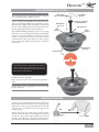
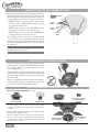
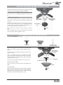
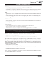
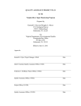
HANOVER™
Hanover™ Owner’s Manual
READ AND SAVE THESE INSTRUCTIONS!
Safety and the proper operation of your Casablanca fan both require a thorough knowledge of the product and proper
installation; therefore, before attempting to install and operate your Casablanca fan, read this owner’s manual completely and
carefully. Retain this manual for future reference.
CAUTION: To avoid possible electrical shock, make certain that electricity is turned off at the circuit breaker or fuse box
before attempting any installation procedure.
CONTENTS
INTRODUCTION
Before You Start . . . . . . . . . . . . . . . . . . . . . . . . . . . . . . . . . . . . . . . . . . . . . . . . . . . . . . . . . . . . . . . . . . . . . . . . . . . . . . . . . 2
Safe Use. . . . . . . . . . . . . . . . . . . . . . . . . . . . . . . . . . . . . . . . . . . . . . . . . . . . . . . . . . . . . . . . . . . . . . . . . . . . . . . . . . . . . . . . 2
MOUNTING RECOMMENDATIONS
General Guidelines . . . . . . . . . . . . . . . . . . . . . . . . . . . . . . . . . . . . . . . . . . . . . . . . . . . . . . . . . . . . . . . . . . . . . . . . . . . . . . . 3
Sloped Ceiling Installations . . . . . . . . . . . . . . . . . . . . . . . . . . . . . . . . . . . . . . . . . . . . . . . . . . . . . . . . . . . . . . . . . . . . . . . . 3
FAN INSTALLATION
Getting Started . . . . . . . . . . . . . . . . . . . . . . . . . . . . . . . . . . . . . . . . . . . . . . . . . . . . . . . . . . . . . . . . . . . . . . . . . . . . . . . . . . 4
Crossbar Mounting Bracket Installation . . . . . . . . . . . . . . . . . . . . . . . . . . . . . . . . . . . . . . . . . . . . . . . . . . . . . . . . . . . . . . . 4
Lag Screw Installation (Optional). . . . . . . . . . . . . . . . . . . . . . . . . . . . . . . . . . . . . . . . . . . . . . . . . . . . . . . . . . . . . . . . . . . . 5
Canopy Installation . . . . . . . . . . . . . . . . . . . . . . . . . . . . . . . . . . . . . . . . . . . . . . . . . . . . . . . . . . . . . . . . . . . . . . . . . . . . . . . 5
Blade Installation. . . . . . . . . . . . . . . . . . . . . . . . . . . . . . . . . . . . . . . . . . . . . . . . . . . . . . . . . . . . . . . . . . . . . . . . . . . . . . . . . 6
Fan Preparation . . . . . . . . . . . . . . . . . . . . . . . . . . . . . . . . . . . . . . . . . . . . . . . . . . . . . . . . . . . . . . . . . . . . . . . . . . . . . . . . . . 6
Hanging the Fan . . . . . . . . . . . . . . . . . . . . . . . . . . . . . . . . . . . . . . . . . . . . . . . . . . . . . . . . . . . . . . . . . . . . . . . . . . . . . . . . . 7
Canopy Electrical Connections. . . . . . . . . . . . . . . . . . . . . . . . . . . . . . . . . . . . . . . . . . . . . . . . . . . . . . . . . . . . . . . . . . . . . . 8
Canopy Hatch Installation . . . . . . . . . . . . . . . . . . . . . . . . . . . . . . . . . . . . . . . . . . . . . . . . . . . . . . . . . . . . . . . . . . . . . . . . . 8
Switch Housing Installation . . . . . . . . . . . . . . . . . . . . . . . . . . . . . . . . . . . . . . . . . . . . . . . . . . . . . . . . . . . . . . . . . . . . . . . . 8
Optional Light Kit Installation . . . . . . . . . . . . . . . . . . . . . . . . . . . . . . . . . . . . . . . . . . . . . . . . . . . . . . . . . . . . . . . . . . . . . . 9
VERSA•TOUCH2™ CONTROL INSTALLATION
Control Bracket Installation . . . . . . . . . . . . . . . . . . . . . . . . . . . . . . . . . . . . . . . . . . . . . . . . . . . . . . . . . . . . . . . . . . . . . . . 10
Changing Transmitter Frequency Setting . . . . . . . . . . . . . . . . . . . . . . . . . . . . . . . . . . . . . . . . . . . . . . . . . . . . . . . . . . . . . 11
Remote Operation. . . . . . . . . . . . . . . . . . . . . . . . . . . . . . . . . . . . . . . . . . . . . . . . . . . . . . . . . . . . . . . . . . . . . . . . . . . . . . . 11
TROUBLESHOOTING TIPS . . . . . . . . . . . . . . . . . . . . . . . . . . . . . . . . . . . . . . . . . . . . . . . . . . . . . . . . . . . . . . . . . . . . . 12
CARE RECOMMENDATIONS . . . . . . . . . . . . . . . . . . . . . . . . . . . . . . . . . . . . . . . . . . . . . . . . . . . . . . . . . . . . . . . . . . . 13
AUTHORIZED SERVICE CENTERS . . . . . . . . . . . . . . . . . . . . . . . . . . . . . . . . . . . . . . . . . . . . . . . . . . . . . . . . . . . . . 14
PRODUCT SPECIFICATIONS . . . . . . . . . . . . . . . . . . . . . . . . . . . . . . . . . . . . . . . . . . . . . . . . . . . . . . . . . . . . . . . . . . . 16
C8U47M AT1206
1
INTRODUCTION
BEFORE YOU START
• CAUTION: RISK OF ELECTRICAL SHOCK! Installation is to be in accordance with the National Electrical Code,
ANSI/NFPA 70-1999, and local codes. All wiring must be performed in accordance with national and local electrical
codes. If you are unfamiliar with the wiring codes, you should use a qualified electrician. To avoid overheating and possible
damage to other equipment, do not install control to a receptacle, fluorescent light fixture, motor operated appliance, or
transformer-supplied appliance.
• This fan is designed to be installed on an existing electrical outlet box. The outlet box must be UL Listed for ceiling fan
installations, if it is not, a new box must be installed. Casablanca extension poles are available for sloped or high ceiling
installations.
• This ceiling fan requires a grounded electrical supply of 120 VAC, 60 Hz and a minimum 15 amp circuit. The maximum
current requirement for the fan with light fixture is 2.83 amps. The fan uses about 1 amp or 100 watts. Maximum light
current is about 1.83 amps or 220 watts of lighting.
• Where wire nuts are employed, be sure all bare wires are within the connectors. When installing the canopy hatch, make
sure all wires are within the canopy and that no wires are being pinched.
• WARNING: Do not bend the blade brackets when installing the brackets, balancing the blades or cleaning the fan. Do not
insert foreign objects in between the rotating fan blades.
• WARNING: To reduce the risk of fire or electric shock, do not use this fan with any solid state speed control device. Use
only the control provided with or recommended for this fan.
Unpacking
Before assembling and installing your ceiling fan, remove all parts from the shipping cartons and check them against the parts
listed in the parts guide. Before discarding packaging material, be certain that all parts have been removed.
For best performance and for your warranty to be valid,
use only genuine Casablanca blades, light fixtures, and accessories.
SAFE USE
• The blades in each pack are matched for equal weight
to assure smooth fan operation. If more than one fan is
being installed, be careful not to mix blades from different
cartons.
Circuit Breaker
(Trip breaker for the
circuit you will be
working on)
Fuse Box
(Remove fuse for the
circuit you will be
working on)
• Inspect the contents of your carton for possible shipping
or handling damage and report any such damage directly
to your authorized Casablanca dealer.
• It is always a good idea to have an assistant to help with
the installation.
• When cleaning, painting, or working near your fan, be
very careful of the fan and blades. Always turn the power
OFF to the ceiling fan before servicing it, working on it,
or replacing lightbulbs.
• Never insert anything into the path of the fan blades while
the fan is in operation.
18" ↑
• Never install a fan over a pool or spa.
• Never operate a fan that has been damaged in any
way. Contact Casablanca Fan Company by calling
1-888-227-2178, or contact your local authorized
Casablanca dealer for assistance in obtaining service.
2
70"↑
84" ↑
HANOVER™
MOUNTING RECOMMENDATIONS
GENERAL GUIDELINES
Before mounting your Casablanca fan, read the following helpful recommendations. The location of the fan, air circulation,
and fan size are all important factors to consider before installation.
Location
Ceiling fans have practical uses in almost every room in your home. We suggest
you follow these mounting recommendations as you decide where to install
your Casablanca fan.
•
•
•
•
For safety reasons, the fan blades must be a minimum of 7' above the floor.
Do not locate the fan in a doorway or above a swinging door.
In bedrooms, fans work best when mounted above the foot of the bed.
Over pool tables, be sure to provide plenty of clearance to avoid damage
from pool cues.
• In kitchens be sure to allow for open cupboard doors to clear the fan
blades.
• Do not install a fan close to, or over, a pool or spa. High humidity combined with corrosive gases will destroy the finish and
warp the blades.
Fan Size
Variable fan speed capability permits the use of a full-size 52" fan even in smaller rooms. For very large rooms, two fans may
be needed.
SLOPED CEILING INSTALLATIONS
SUGGESTED EXTENSION POLE LENGTHS
Ceiling Height
8' 0"
8' 6"
9' 0"
9' 6"
10' 0"
11' 0"
12' 0"
13' 0"
14' 0"
Pole Length
Extension
Pole
Standard
Standard
6"
12"
12"
18"
24"
36"
48"
Maximum
Hang-Tru®
angle 32º
Blades must be a
minimum of 7 feet
above the floor
7' minimum
When to Use Extension Poles
For best performance and best appearance, an extension
pole should be used with your Casablanca fan when
installing on high (cathedral) ceilings or sloped ceilings.
Casablanca offers standard poles in increments of 6" up
to 5'. Custom poles are available in lengths up to 9'9". See
your Authorized Casablanca Dealer for details.
NOTE: Fan may wobble or vibrate if pole length is not long
enough and inside blade is too close to downslope or side
wall. Extending pole length will usually solve problem.
EXAMPLE 1
EXAMPLE 2
Calculation of 32°
Use the tear-off Ceiling Angle Template card inserted in this
manual. It provides you with a simple “go” or “no-go” for
installing your fan on a sloped ceiling.
EXAMPLE 3
This slope is less than 32º.
It is OK to install your fan.
This slope is 32½. This is the maximum
slope that will allow the fan to hang
straight down. It is OK to install your fan.
This slope is more than 32º.Your fan will not
hang straight down, an adaptor is necessary.
Contact your local Authorized Casablanca
Dealer in regards to purchasing a “Sloped
Ceiling Adaptor.”
3
FAN INSTALLATION
GETTING STARTED
Installing a New Ceiling Fixture Outlet Box
Using Existing Ceiling Fixture Outlet Box
If you do not have an existing fixture located where you wish
to place your Casablanca fan, an approved ceiling fixture
outlet box must be installed and wired.
After turning the power OFF at its source (either circuit
breaker or fuse box), lower the old fixture and disconnect
the wiring. Check the ceiling fixture outlet box to be sure
that it is marked “Approved for Ceiling Fan Mounting.” If
it is not, a new box must be installed.
WARNING!
To reduce the risk of fire, electrical shock, or
personal injury, mount to outlet box marked
“Acceptable Fan Support of 22.7 kg (50 lbs.) or
less” using the mounting hardware provided with
the outlet box.
Note: The weight of this fan is 34 pounds.
CROSSBAR MOUNTING BRACKET INSTALLATION
CEILING HARDWARE (not to scale)
Crossbar Mounting Bracket
Pack A:
Lag Bolt & Washer (1),
Crossbar Screws & Washers (2)
Note: After removing the old fixture, check the outlet box
to ensure it is supported by a joist or beam across its upper
surface. If not, a 2"x4" stud must be installed.
Step 1a. Remove the knockout plug in the center of the
outlet box or drill a 1/2-inch hole for the lag screw to pass
through. Then drill a 1/4-inch guidehole into the joist or
beam to a depth of 3 inches.
Step 1b. Route the outlet box wires through the keyhole
slot of the crossbar mounting bracket as shown. Attach
the crossbar mounting bracket to the outlet box with the
screws provided, assuring that the outlet box wires are not
pinched by the washer.
Joist
Ceiling-Fan-Approved Wiring
Box
Crossbar Mounting
Bracket
Green Ground Wire
CAUTION:
To reduce the risk of personal injury, use only the
mounting hardware provided with the approved
outlet box to install the crossbar mounting
bracket.
WARNING!
Support directly to building structure only.
4
Wire Nuts (4)
1" x 8-32
Roundhead Screw
Ceiling Wiring
Ridge side down
Washer
HANOVER™
LAG SCREW INSTALLATION (OPTIONAL)
NOTE: This step is required only under two conditions: If
the fan weighs 36 lbs. or more (which does not pertain to
this fan) or if the existing ceiling fixture outlet box needs
to be modified for a ceiling fan application (for example,
if the house is not new construction and you are replacing
an existing light fixture). We recommend that the ceiling
box be of sufficient capacity to support the weight of the
fan and light fixture under any conditions. If in doubt
whether you need to install the lag screw, consult a qualified
electrician.
Step 2 (optional). With the large washer attached, pass the
lag screw (Pack A) through the center hole of the crossbar
mounting bracket and screw into guide hole. Tighten until
outlet box is mounted firmly to beam. This box must be
secured to the ceiling firmly.
CANOPY INSTALLATION
CANOPY HARDWARE (not to scale)
Pack B:
Canopy Screws and
Lock Washers (5)
Canopy Hatch
Canopy
Step 3. Attach the canopy to the crossbar mounting bracket
with three of the 8-32 x 21/2" long canopy screws (Pack
B) and lock washers provided with your Casablanca fan.
Tighten using the provided screwdriver until snug against
the ceiling.
NOTE: On sloped ceilings, align the canopy opening with
the top or peak of the room.
Feed outlet box
wires through
canopy opening
Canopy
Lock Washer
Canopy Screw
5
BLADE INSTALLATION
BLADE HARDWARE (not to scale)
Blades (4)
Blade Irons (4)
Pack C:
Blade Screws and Washers (17)
Pack D:
Blade Iron Screws (9)
Attach Blade Irons
Step 4. Using the screws in Pack C and the provided
screwdriver, attach the blades to the blade holders by
aligning the screwholes of the blade iron with the holes
in the blade. Attach the blade iron using the four blade
screws provided for each blade, as shown. Tighten securely
by hand only.
Blade Installation:
Step 5. Using the screws in Pack D and the provided
screwdriver, attach the blade assembly to the motor as
shown. Tighten screws by hand only.
TIP: For balancing purposes, loosely install all four blades
to the motor before tightening the blade screws securely.
CAUTION:
Blade screws must be tightened securely before
operating the fan.
FAN PREPARATION
PERMA•LOCK™ HARDWARE (not to scale)
Uplight Lightbulbs S-11 25-watt (4)
Allen Wrench
IMPORTANT SAFETY INFORMATION:
Before starting the installation of your ceiling
fan, install the threaded downrod into the motor
coupling and lock the assembly.
Prepare for fan installation as follows:
Step 6a. Remove the paper shield from the motor.
Step 6b. Route the wires through the Perma•Lock™
downrod and ball assembly.
6
3" Perma•Lock™ Downrod
and Ball Assembly
HANOVER™
FAN PREPARATION (CONT.)
TIP: The downrod has a tapered thread that is designed
to lock completely when installed correctly.
Step 6c. Using the provided Allen wrench (attached to the
paper motor warning shield), remove the Allen set screw
from the hanger adaptor and set it aside. Insert the downrod
into the motor coupling and turn it clockwise until it stops
turning, ensuring that the pole has bottomed out.
Step 6d. While holding the adaptor motor cover securely,
insert the set screw and tighten it with the provided Allen
wrench to ensure safe operation of your fan. If it is tight
enough, you should not be able to turn the downrod
counterclockwise with your hands. If in doubt, tighten
the set screw with the Allen wrench until you cannot turn
it any further.
Motor Wires
(leave at least 6" long)
Allen Wrench
Ground Wire
(green)
Perma•Lock™ Downrod
and Ball Assembly
Tapered thread
Allen
Set Screw
Motor
Coupling
Motor Housing
Assembly
Caution Shield
CAUTION: Failure to fully lock in the downrod
before securely tightening the Allen set screw may
cause the fan to separate from the downrod and
fall during normal operation.
Install Incandescent Lightbulbs
Step 7. Screw in four 25-watt incandescent lightbulbs as
shown.
NOTE: When replacing lightbulbs, be sure to use only
25-watt maximum.
HANGING THE FAN
Step 8a. To hang the fan body in the canopy, hold the fan
body firmly and insert the ball into the canopy opening.
Check that no wires were pinched. Rotate the fan body
until the slot in the ball fits into the pin opposite the
canopy opening.
Step 8b. Trim excess motor wires, leaving at least 6 inches
above the downrod. Strip 1/2-inch insulation from the end
of each wire using a wire stripper (available at your local
hardware store). The splices after being made should be
turned upward and pushed carefully into the outlet box.
Ball
Slot
Pin
7
CANOPY ELECTRICAL CONNECTIONS
Step 9. Attach the fan wires to the ceiling fixture outlet box
wiring by placing the bare ends of the wires side by side and
then securing with a wire nut. Test that the connection is
secure by pulling on the wire nut. Connect in this order:
• GREEN leads from mounting plate and downrod
assembly of fan to GROUND conductor of power
source. Secure with wire nut.
• WHITE wire from fan to white NEUTRAL wire in
ceiling fixture outlet box. Secure with wire nut.
• BLACK power wire from fan to black POWER wire
in ceiling outlet box. Secure with wire nut.
Wire Nut
2 Black
Wires
2 White
Wires
3 Green
Wires
After making the wire connections, the wires should
be spread apart with the grounded conductor and the
equipment-grounding conductor on one side of the outlet
box and the ungrounded conductor on the other side of
the outlet box.
NOTE: If the color of your ceiling wires differs from that
described, consult an electrician.
CANOPY HATCH INSTALLATION
Step 10a. Tuck the wires into the canopy with the wire nuts
pointed upwards, so that the WHITE and BLACK wires
are on opposite sides of the canopy and all wires are clear
of the canopy opening.
Step 10b. Install canopy hatch with the last canopy screw
and lock washer using the provided screwdriver. To do this,
tilt the fan body away from the hatch opening. Tighten
the screws firmly.
Step 10c. Straighten the fan, then check to ensure that there
is no movement between the canopy and the ceiling or the
Perma•Lock™ downrod and the ball assembly.
SWITCH HOUSING INSTALLATION
SWITCH HOUSING HARDWARE (not to scale)
Switch Housing
Mounting Plate
No Light Cap
Adapter Plate
Step 11a. Using screws from Pack E and the provided
screwdriver, install two screws into the motor bottom housing
as shown.
Step 11b. Route the light connector wires through the switch
housing mounting plate as shown.
Step 11c. Align the switch housing mounting plate with
the two screws in the motor bottom housing and turn
counterclockwise to align the keyhole slots in the plate with
the two screws as shown.
8
Switch Housing
Cap
Switch Housing
Mounting Plate
Pack E:
Motor & Switch Housing Mounting Plate
Screws (6)
Motor Housing
Screws
HANOVER™
SWITCH HOUSING INSTALLATION (CONT.)
Step 11d. Install the third screw and securely tighten all three
screws by hand only using the provided screwdriver.
Note: If you are not installing the optional light kit proceed
to step 12. If you are installing the light kit, proceed to step
13.
Installing the No Light Cap
Step 12a. Using Pack F and the screwdriver provided; install
each of the 3 screws into the switch housing mounting plate,
as shown.
Step 12b. Align the keyhole slots in the cap adaptor plate with
the three screws in the switch housing mounting plate and turn
counterclockwise to align the keyhole slots with the three screws.
Securely tighten all three screws, by hand only.
Step 12c. Remove the finial from the no-light cap adaptor
plate.
Step 12d. Install switch housing cap. Thread finial onto threaded
rod of cap adapter plate and tighten securely.
Switch Housing
Mounting Plate
Screws
No Light Cap
Adapter Plate
Switch Housing
Cap
Finial
OPTIONAL LIGHT KIT INSTALLATION
LIGHT KIT HARDWARE (not to scale)
Socket Plate
Glass Shade
60-watt B-10 bulb
(Candelabra-base)
Step 13a. Using pack “E” and screwdriver provided; install
three screws into the Light Assembly Adapter Plate, as
shown.
Switch Housing
Mounting Plate
Screws
Step 13b. Connect the Light Assembly connector to the
motor connector.
Step 13c. Carefully tuck the wires and align the keyhole
slots in the Light Assembly with the three screws in the
adaptor plate. Turn counterclockwise to align the keyhole
slots with the three screws.
Step 13d. Securely tighten all three screws by hand only.
Lightbulbs
Socket Plate
Install Incandescent Bulbs
Step 14. Screw in two 60-watt B-10 Candelabra-base
bulbs.
Glass Shade
Glass Installation
Step 15. Remove the finial from the No-Light Cap Adaptor
Plate. Insert the threaded rod from the Light Assembly
through the hole in the glass shade, as shown. Twist the
finial onto the threaded rod. Tighten securely.
Finial
9
VERSA•TOUCH2™ CONTROL INSTALLATION
VERSA•TOUCH2™ HARDWARE (not to scale)
12v Battery
W-73
Control
Wood
Screw
1" (2)
Drywall Anchor
6-32 (2)
Screw
6-32 X 3/8"
(2)
Screw
6-32 X 1"
(2)
W-73
Control Holder
CONTROL BRACKET INSTALLATION
SAFETY FIRST: To reduce the risk of electrical shock, this fan must be installed with an isolating wall control/switch.
CAUTION! Do not use with wall dimmer.
WARNING: To reduce the risk of fire or electric shock, do not use this fan with any solid state speed control device.
Use only the control provided with this fan.
Step 16. Follow instructions for the type of transmitter control bracket you will be using.
Standard
Toggle
Switch
Inner
Mounting
holes
Rocker
Light
Switch
Outer
Mounting
Holes
Switch
Cover
Plate
Switch
Cover
Plate
Control
Bracket
Control
Bracket
Standard Light Switch
Rocker Light Switch
Step A. Remove the two screws holding the switch cover
plate. Do not remove the cover plate.
Step A. Break off the two tabs by pushing outward.
Step B. Orient the control bracket as shown and line up the
two inner mounting holes with those on the switch.
Step C. Insert and tighten the screws using the provided
screwdriver.
Wall Installation
Step A. L ocate a 2x4
wall stud in a convenient
location.
Step B. Remove the two screws holding the switch cover
plate. Do not remove the cover plate.
Step C. Orient the control bracket as shown and line up
the two inner mounting holes with those on the switch.
Step D. Insert and tighten the screws using the provided
screwdriver.
NOTE: The wall anchors and 6-32 x 1" screws may
be used in situations where mounting to a stud is not
possible. Use the inner mounting holes. After securing
the anchor, discard the anchor’s pointed screws and use
the 6-32 decor ovalhead screws supplied.
Step B. Orient the control
bracket as shown over the
2x4 stud.
Step C. Insert the 1" wood
screws in either the inner or
outer mounting holes and
tighten using the provided
screwdriver.
Anchor
Panhead
Screw
Wood
Screw 1"
10
Drywall Anchor
Decor Ovalhead Screw
6-32 X 1"
HANOVER™
REMOTE OPERATION
Fan Control
To start the fan. Press the selected speed button to run the fan at the desired speed.
Send Signal
LED
LOW=Low speed MED=Medium speed HIGH=High speed
UPTo turn off the fan, press the FAN OFF button.
Airflow Direction
MED
To reverse the airflow, press the REVERSE button. REVERSE operates at any speed
whether the fan is on or off. The fan returns to its set speed after reversing.
LOW
Light Control
Turn the light on or off independently from the fan by pressing the LIGHT rocker switch.
(Press the left side for the uplight, right side for the downlight, and the middle for both.)
If you press the button for more than 0.7 seconds, it becomes a dimmer. The light varies
from “bright" to “dim” over approximately 8 seconds. If you continue to hold the LIGHT
button, this sequence will reverse when the light reaches its brightest or dimmest level. REVERSE
Release the button when the desired level is reached.
Auto Resume
Quick (pressing less than 0.7 seconds) on/off operation of the LIGHT button maintains
the desired brightness level set previously.
DOWNLIGHT
HIGH
FAN
OFF
CHANGING TRANSMITTER FREQUENCY SETTING
Note: All fans leave the factory set to “00000.”
Versa•Touch 2
Control
(back)
You will only have to change the dip switch settings in the remote
if you are using more than one fan in the same area and want to
control them separately.
Step 1. At the circuit breaker or fuse box, turn the power off for
the fan you want to change.
Step 2. Open the battery door of the Versa•Touch control and
remove the batteries.
Step 3. Change the dip switch settings, assuring that they are
different from the previously installed Versa•Touch fan.
Step 4. Reinstall the batteries and the battery door on the
control.
Dip Switch
set to “10000”
Dip Switch
set to “01001”
Step 5. At the circuit breaker or fuse box, turn the power back on
for the fan whose frequency you are changing.
WARNING!
Note: You may want to label your controls to assure you
do not mix them up.
Do not turn the power off at the circuit breaker, then
back on, for the previously installed Versa•Touch2
fan(s), as you may inadvertently change the
frequency settings for it as well.
2
If the fan is not functioning after installation:
Step 1. Check to make sure that batteries are installed correctly
in the control.
3
Step 2. Turn the power off to the fan (from the circuit breaker)
for at least 5 seconds.
Step 3. Turn the power back on (at the circuit breaker) and push
the HIGH, MED, and LOW buttons–in that order–within 20
seconds. The fan should now function properly.
Circuit Breaker
or Fuse Box
1
Press in this order to set new
frequency:
1. HIGH
2. MED
3. LOW
11
TROUBLESHOOTING TIPS
Please refer to this troubleshooting guide before requesting service or contacting your dealer for assistance.
PROBLEM
POSSIBLE REMEDIES
Fan will not start
• Check the main circuit fuses, circuit breakers, and wall switch position. Check
all wire connections. Make sure the power is turned off during this inspection.
• The battery is weak. Install a fresh battery.
• The fan receiver is defective. Replace fan receiver.
• Check the frequency setting: Turn the power off at the circuit breaker, only for
the fan that is not functioning. Check that the jumper switches match in both
the receiver and the transmitter.
Fan wobbles or shakes excessively
• Be sure the canopy pin is set properly into the slot on the ball.
• Check that the bladeholders have not been bent during installation and the blades
are balanced.
• The hanger bracket and/or ceiling outlet are attached too loosely. Make sure
the hanger bracket is attached tightly to the ceiling outlet box and the downrod
assembly is secured firmly.
• The downrod is attached to downrod base too loosely. Make sure all the screws
are securely tightened.
Fan is noisy during operation
• Check and tighten the light fixture retaining screws, glass shade screws, and/or
lightbulb(s).
• Tighten the canopy screws and mounting plate assembly. Make sure the wire
nuts inside the canopy and switch housing are not touching the metal parts and
that they have not fallen off the wire splices. Tighten as necessary.
• Tighten the blade holders to the flywheel (or direct drive motor) and the blades
to the bladeholder screws.
• Make sure all screws in the motor housing are snug but not overly tight.
Fan does not run on low speed
• If fan is new, it may need to be “broken in.” Run at high speed for several days.
Battery life is short
• Replace with alkaline batteries.
Light works, but fan does not work
• The fan wires are not connected properly. Follow the instructions in Step 9.
Fan and light run only on full speed
• The fan receiver is defective. Replace fan receiver.
Fan is missing one speed
• The fan receiver is defective. Replace fan receiver.
Fan does not change speed, but light works • The fan receiver is defective. Replace fan receiver.
Reverse does not work
• The fan receiver is defective. Replace fan receiver.
Fan starts working by itself
• There is frequency interference. Change frequency as described on Page 11.
Fan operates only when transmitter is close • Check that antenna wire is not touching metal plate.
Fan works, but light does not dim
• The fan receiver is defective. Replace fan receiver.
Fan works, but light does not work
• The fan receiver is defective. Replace fan receiver.
• The light socket is broken. Replace socket.
• A lightbulb is defective. Replace lightbulb.
12
HANOVER™
CARE RECOMMENDATIONS
Fan Finishes
• For cleaning, a soft brush or lint-free cloth should be used to prevent scratching the finish.
• A vacuum cleaner brush nozzle can remove heavier dust.
• Surface smudges or an accumulation of dirt and dust can be removed easily by using a mild detergent and slightly dampened
soft cloth. An antistatic agent may be used, but never use abrasive cleaning agents as these will damage the finish.
Blades
• Wood-finish blades should be cleaned with a furniture polishing cloth. Occasionally, a light coat of furniture polish may be
applied for added protection and beauty.
• For painted and high-gloss blades, surface smudges or an accumulation of dirt and dust can be removed easily by using a
mild detergent and slightly dampened soft cloth. An antistatic agent may be used, but never use abrasive cleaning agents as
these will damage the finish.
No Need for Lubrication
• Never lubricate this fan! The precision motor at the heart of your Casablanca fan features sealed bearings that are lubricated
for life.
• Do not attempt to oil the motor.
Changing Lightbulbs
• Be sure to turn the power to OFF at the wall switch or circuit breaker before changing lightbulbs.
• Replace bulbs with the same type as you removed from the light fixture.
• The maximum wattage rating for this fan’s light kit is 100 watts for the uplight, 120 watts for the downlight.
For questions or to locate the nearest Casablanca Authorized Service Center call toll free: 1-888-227-2178
or visit us on the web at: www.casablancafanco.com
This device complies with Part 15 of the FCC rules. Operation is subject to the following two conditions:
1. This device may not cause harmful interference.
2. This device must accept any interference received, including interference that may cause undesired operation.
This equipment has been tested and found to comply with the limits for a class B digital device, pursuant to Part 15 of the
FCC rules. These limits are designed to provide reasonable protection against harmful interference in a residential installation.
This equipment generates, uses, and can radiate radio frequency energy and, if not installed and used in accordance with the
instructions, may cause harmful interference to radio communication. However, there is no guarantee that the interference
will not occur in a particular installation. If this equipment does cause harmful interference to radio or television reception,
which can be determined by turning the equipment off and on, the user is encouraged to try to correct the interference by
one or more of the following measures:
• Reorient or relocate the receiving antenna.
• Increase the separation between the equipment and receiver.
• Connect the equipment into an outlet on a circuit different from that to which the receiver is connected.
• Consult the dealer or an experienced radio/TV technician for help.
NOTE: Any changes or modifications to the transmitter or receiver not expressly approved by Casablanca Fan Company
may void one's authority to operate this remote control.
13
AUTHORIZED SERVICE CENTERS
STATE/CITY
ZIP
SERVICE CENTER NAME
PHONE
ALASKA
Anchorage
99518
Bering Sea Eccotech
907-563-7988
ALABAMA
Mobile
Tuscaloosa
36618
35405
Azalea City Service Ctr.
Lighting Plus
251-341-0663
205-345-8900
ARIZONA
Green Valley
Mesa
Mesa
Phoenix
Phoenix
Prescott
Scottsdale
Sedona
Tucson
Tucson
Tucson
Youngtown
Yuma
85614
85204
85210
85032
85019
86305
85254
86336
85735
85716
85711
85363
85364
Goble Electric
Gallery of Fans
Loud Inc. dba Fans Plus
Brasswinds Fan Doctor
Fantastic Electric
Marc Parent
Vandervoort Electric
Oak Creek Audio
Desert Breeze Fan & Elec.
Illuminations
Sun Lighting Company
Brasswinds Fan Doctor
Curley’s Litehouse
520-625-4938
480-962-0477
480-827-9302
602-482-1881
602-866-1090
928-778-5935
602-996-9637
928-282-5625
520-623-4646
520-325-3031
520-322-4303
623-933-0240
928-783-6931
ARKANSAS
Little Rock
72212
The Randy Hall Co. Inc.
501-227-9915
CALIFORNIA
Auburn
Bakersfield
Bakersfield
Cathedral City
Cerritos
Chico
Clovis
Folsom
Fresno
Fresno
Fresno
Glendale
Grass Valley
Huntington Beach
Jamestown
Los Alamitos
Manteca
Mission Viejo
Modesto
Moorpark
Murrieta
Newhall (Santa Clarita)
Pleasanton
Rancho Mirage
Redding
Riverside
Sacramento
San Diego
San Francisco
San Marcos
San Marcos
San Rafael
Santa Clara
Santa Cruz
Santa Maria
Santa Rosa
Saugus
Shingle Springs
South Lake Tahoe
Stockton
Tarzana
Temecula
Tulare
Valencia
95603
93306
93309
92234
90703
95928
93612
95630
93711
93704
93710
91208
95945
92647
95327
90720
95336
92691
95350
93021
92562
91321
94588
92270
96002
92505
95819
92111
94109
92069
92069
94901
95051
95062
93455
95404
91350
95682
96150
95205
91356
92592
93274
91354
The Fan Doctor
Hillcrest Lighting
RB Electric & Lighting
R & R Service
Comforts of Home
J & J Lighting
Omega Services Inc.
Folsom Lighting Co.
James & Co. Lighting
Larry McCollum
The Energy Saving House
Fantastic Fan Service
Accent Lighting
Trading Post Fan Company
Da Silva’s Lamp & Clg.
Jaben Holdings
Manteca Lighting
Moore’s Sew, Vac, & Fan
Phillips Lighting & Home
R.J. Sieg Elect. Co.
Fan Diego
Dan Martin
S & L Lighting Services
Fan Diego
North Valley Lighting
Verne Smith
A & A Light Fixtures
Fan Diego
House of Fans Inc.
Fan Diego
RD Electrical Cont.
Raffles Fans
Sal Zamora’s Fan Repair
Riverside Lighting
Ever-Ready Electric
Asef’s Appl. & Elec. Svc.
Valley Breeze Fan Co.
John Rozowski Const.
Tahoe Pool Service
Risso Electric
Hye Lighting Co.
Tab Electric
Anchor Lighting
Fantastic Fan Service
530-823-8768
661-324-0649
661-831-2438
760-324-2942
562-865-6666
530-342-1815
559-299-0495
916-983-5575
559-486-7900
559-438-5764
559-432-1500
800-800-3871
530-477-5483
714-848-4353
209-984-4035
562-594-1249
209-823-1999
949-580-2520
209-524-6287
805-523-7434
951-600-7867
661-252-5769
925-895-3762
760-779-9916
530-221-6277
951-687-9552
916-452-7641
858-292-9244
415-885-1947
760-743-3267
760-727-1215
415-456-6660
510-742-5560
831-423-7411
805-934-7091
707-575-3737
800-339-3267
530-677-3850
530-541-4958
209-466-0781
818-345-5544
951-303-0850
559-688-0696
800-800-3871
COLORADO
Colorado Springs
Denver
Fort Collins
Longmont
80903
80229
80525
80504
Home Lighting
M.D Electric
Light Center
L A Enterprises
719-471-3520
303-288-7988
970-226-3430
800-299-0222
TYPE
WTS
WTS
ISO
ISO
ISO
ISO, WTS
ISO
ISO
ISO
ISO
ISO, WTS
WTS
ISO, WTS
ISO
ISO, WTS
ISO
ISO
ISO
ISO
ISO
ISO
WTS
ISO, WTS
WTS
WTS
WTS
TYPE OF SERVICES OFFERED:
ISH = IN-HOUSE SERVICE
14
ISO = IN-SHOP ONLY WTS = SERVICES ONLY WHAT THEY SELL
STATE/CITY
SERVICE CENTER NAME
PHONE
TYPE
COLORADO (Continued)
Longmont
80501
Loveland
80538
ZIP
Lumenarea.com, Inc.
Fireside Lighting
303-485-6800
970-669-3540
WTS
WTS
CONNECTICUT
Bridgeport
Clinton
East Hartford
Greenwich
Hartford
New Hartford
New Haven
Willington
Woodstock
06605
06413
06118
06830
06114
06057
06511
06279
06281
Federal Elect. Const. Co.
Graham Co.
Graham Co.
Fashion Light Center
Connecticut Ltg. Center
B.W. Morse & Sons Inc.
New Grand Light
George Opalenik
Randy Matteau
203-334-6455
800-942-5575
800-942-5575
203-869-3098 ISO, WTS
860-249-7631
ISO
860-379-9855
203-777-5781
ISO
860-684-4558
860-963-8979
DELAWARE
Dover
New Castle
19901
19720
Bruce Drajem
Eric Shurr
302-734-7737
302-998-5147
DISTRICT OF COLUMBIA
Washington
20007
Fan Fair
202-342-6290
FLORIDA
Bonita Springs
Boynton Beach
Brandon
Coral Gables
Davie
Fern Park
Gainesville
Jacksonville
Maitland
Naples
Nokomis
Orlando
Port Charlotte
S. Daytona
Spring Hill
Tallahassee
Tarpon Springs
Winter Haven
Winter Haven
34135
33437
33511
33134
33330
32730
32608
32217
32751
34109
34275
32806
33952
32119
34606
32303
34689
33880
33884
Goodwin Electric
CMS
Lumenair Lighting & Fan
Michael Hansen
Laserland Inc.
Henry Electric Co.
Authorized Appliance
Authorized Appliance Serv.
Henry Electric Co.
Wilson Fans & Lighting
Graham Electrical Cont.
Mid-Florida Fan
Jacksons Lighting
Bob’s Fix-It
Fan Doctor
Jim Laczko
Peter Lontakos
All About Fans
Cypress Ltg. Showroom
239-649-8880
561-736-0170
813-653-3460
ISO
305-444-4111
954-558-3743
407-834-4032
ISO
352-375-3886
ISO
904-737-5312
ISO
407-834-4032
ISO
239-592-6006 ISO, WTS
941-486-8190
407-893-6226
941-625-0044
WTS
386-761-4055
352-683-4428
850-562-4661
727-938-8895
863-299-9593
863-676-9097
GEORGIA
Grayson
30017
RG Tenney Electric
770-378-9255
HAWAII
Aiea
Hilo
Kahului
Kailua-Kona
Kaulua Kona
Kihei
96701
96720
96732
96740
96740
96753
Fan Shop Inc.
Bay Lighting & Design
Read Lighting
Kona Coast House of Lights
Ku’s Electronic Service
Fans Etc.
808-488-1221
808-961-5688
808-871-8995
808-329-0748
808-329-4346
808-875-6347
IDAHO
Idaho Falls
Meridian
83402
83642
Home Lighting
S-K Electric, Inc.
208-523-2300
208-941-6264
ILLINOIS
Centralia
Champaign
Champaign
Chicago
Cornland
Frankfort
Mchenry
Mokena
Normal
Princeton
Quincy
Smithton
Trenton
Urbana
Yorkville
62801
61821
61821
60630
62519
60423
60051
60448
61761
61356
62305
62285
62293
61801
60560
Baker Appliance Repair
Springfield Electric Supply
Terry Gobble
D & S Fan Specialist
Delmar Veech
KKA Services
Northwest Electrical
KKA Services
Kirk Small Appliance
Elmore Electric Inc.
Heintz Lighting Center
John Hassenstab
Light Brite Distributing
Terry Gobble
Unified Supply, Inc.
618-532-8437
217-351-7600
217-384-5891
847-824-2430
217-364-4124
815-464-6714
815-363-1800
815-464-6714
309-452-5248
815-643-2354
217-223-0101
618-236-3018
618-224-7314
217-384-5891
630-553-0660
INDIANA
Evansville
Fort Wayne
Greenfield
Indianapolis
Valparaiso
47711
46805
46140
46222
46383
Michael Baxter
Carl Smith
D & D Repair
Indiana Lighting Center
D & K Electric
812-453-6498
260-484-7295
317-467-0600
317-293-9333
219-464-7576
ISO
WTS
ISO
ISO
ISO
ISO
ISO
HANOVER™
STATE/CITY
ZIP
SERVICE CENTER NAME
PHONE
TYPE
IOWA
Carroll
Cedar Rapids
Coralville
Davenport
Des Moines
Monticello
Sioux Center
Sioux City
51401
52404
52241
52803
50311
52310
51250
51106
J & L Electric Inc.
Acme Electric Company
Ralston Creek
Shaw Electric
Advanced Lighting
Rem Electric
Hills Home Systems
Diversified Electronics
712-792-2444
ISO
319-365-8677
319-351-2189 ISO, WTS
563-323-3611
515-255-5009
WTS
319-465-3346
712-722-4905
712-276-1034
KANSAS
Emporia
Lenexa
Manhattan
Overland Park
Overland Park
Overland Park
Overland Park
Salina
Wichita
66801
66215
66502
66213
66210
66223
66212
67401
67208
C.A.P.
Rensen House Of Lights
Endacott Lighting
Kal Electric
Randy Russell
Western Chandelier Co.
Wilson Fans & Lighting
Salina Appliance Showroom
Accent Lighting
620-342-0448
913-888-0888
785-776-4472
913-897-6767
913-338-5330
913-685-2000
913-642-1500
785-827-1420
316-636-1278
KENTUCKY
Louisville
40205
Kaelins, Inc.
502-454-8938
LOUISIANA
Baton Rouge
Houma
Lafayette
Lake Charles
Metairie
Monroe
New Iberia
70815
70363
70501
70601
70006
71201
70560
Total Home Service
Gulf South Armature Inc.
Acadia Service Co.
Josephs Electrical Center
Romaine’s
Albert Surlco
Walet’s Inc.
225-272-7725
985-872-0486
337-233-8910
337-436-4930
504-887-7077
318-699-0619
337-364-7486
MAINE
South Portland
04106
T.A. Napolitano Inc.
207-799-0538
MARYLAND
Forestville
Frederick
Fulton
White Hall
20747
21704
20759
21161
Burgess Lighting & Dist.
GL Fan Service
GL Fan Service
BT Electric
301-568-8000 ISO, WTS
301-831-4925
IHS
301-831-4925
IHS
410-329-6353
MASSACHUSETTS
Belmont
Bridgewater
Cochituate
Danvers
Dennis
Natick
New Bedford
Orleans
S. Attleboro
W. Springfield
Worcester
02478
02324
01778
01923
02638
01760
02740
02653
02703
01089
01603
H.O Electric
Biltcliffe Electric
J.G. Electric Co. Inc.
Plaza Lighting
Rick Sexton
J.G. Electric Co Inc.
Vander Electric & Equipment
Associated Electrical
A J Electric
Jalbert Electric
Edward A. Tortora
617-489-6324
508-697-7630
508-653-3042
978-774-7801
508-385-7536
508-653-3042
508-993-6383
508-255-4589
508-761-5021
413-734-4976
508-755-3735
MICHIGAN
Belleville
Birmingham
Grand Rapids
Howell
Lansing
Lansing
Portage
Traverse City
48111
48009
49512
48855
48906
48917
49024
49686
Mike Ayerst
21st Century Electric
Grand Rapids Lighting Ctr.
Lightning Elec. Inc.
Integrity Electric Inc.
Largent Enterprises
Hodgson Light & Log
Lighting & Fan Service
734-699-9698
248-645-6464
616-949-4931 ISO, WTS
810-227-3375
517-484-0300
517-327-6161
800-451-0860
WTS
231-938-1332
MINNESOTA
Baxter
Burnsville
Eden Prairie
Maplewood
Minneapolis
Minneapolis
Rochester
56425
55336
55344
55109
55422
55411
55906
The Light Depot
Fan Man
Fan Man
North Country Electric
Leo’s Elec. Sales & Service
Penn Elec. Motor Service
Kroupa’s Electronics
218-829-0770
952-898-2754
952-941-9243
651-486-7099
763-546-5625
612-588-5333
507-361-1280
MISSISSIPPI
Madison
39110
Jackson Service Ctr.
601-856-9469
MISSOURI
Branson
Springfield
St. Louis
65616
65807
63123
The Light House Gallery/Loyds
The Light House Gallery/Loyds
Leinweber Service Co.
417-334-2171
417-334-2171
314-892-8177
MONTANA
Helena
Kalispell
59601
59901
Supreme Lighting
Lasalle Lighting
406-442-8200
406-752-2424
IHS
ISO
ISO
ISO
ISO
IHS
ISO
ISO
ISO
ISO
ISO
ISO
ISO
ISO
ISO
ISO
STATE/CITY
ZIP
SERVICE CENTER NAME
PHONE
TYPE
MONTANA (Continued)
Missoula
59801
Western Montana Lighting Supply 406-543-7166
ISO
NEBRASKA
Grand Island
Lincoln
Norfolk
Omaha
Omaha
68803
68510
68701
68104
68144
Quality Sew & Vac
Lincoln Lighting Center
The Power Station
D & L Electronics
Oak Hills Electric Inc.
308-382-7310
402-476-1297
402-371-6671
402-571-5233
402-691-4567
ISO
NEVADA
Henderson
Las Vegas
Sparks
89015
89119
89431
KS & S Electric, LLC
Fanco
Eagle Electric, Inc.
702-222-9306
702-898-8522
775-356-7300
NEW HAMPSHIRE
Nashua
Newmarket
03060
03857
Affordable Fans Etc.
Edward Heine
603-759-8332
603-659-5999
NEW JERSEY
Chester
Hillsborough
Jackson
Linwood
Morris Plains
Mullica Hill
Park Ridge
Randolph
Thorofare
Trenton
W. Long Branch
Washington
07930
08844
08527
08221
07950
08062
07656
07869
08086
08619
07764
07882
Chester Lighting, Inc.
Top Line Electric
Robert Rolzhausen
Jack Breslau
Manny Herrera
Stephen Rice
Krell Lighting
Anthony Makomaski
Harry R. Habicht
Wiring Unlimited
No Shorts Electric
C.P. Orlando
908-879-7200
908-431-1888
732-363-3729
609-601-1797
973-993-1137
856-223-8645
201-391-7685
908-475-5569
856-845-2541
609-584-1122
732-222-4228
908-689-4750
NEW MEXICO
Albuquerque
Albuquerque
Albuquerque
87112
87109
87123
A-1 Lamp Doctor
B-Electric Inc.
Frank’s Electric LLC
505-296-5050
505-828-0241
505-293-6724
NEW YORK
Amherst
Amherst
Bedford Hills
Brooklyn
Brooklyn
Brooklyn
Buffalo
Buffalo
Carle Place
Commack
Commack
East Meadow
Glens Falls
Hastings
Long Beach
Lynbrook
New York
Newburgh
Plainview
Poughkeepsie
Queensbury
Rego Park
Rochester
Schenectady
Shokan
Staten Island
Staten Island
Staten Island
Troy
Yonkers
14226
14228
10507
11204
11219
11223
14206
14215
11514
11725
11725
11554
12801
13076
11561
11563
10003
12550
11803
12601
12804
11374
14620
12303
12481
10301
10312
10304
12180
10704
Royalite Lighting
Shanor Lighting Center
Bedford Ltg
Jerry Piccolino/J&R Svc.
Main Lamp Corp.
Manhattan Lights
Craftmasters Servicenter
The Fan Collection, Inc.
Elements
Air-Tek
Turnpike Appliance
C.D. Service
Dean Electric
Electrical Work By Marty
Nick’s Improvement Company
Shaderite-PZ Repair
Superior Light & Fan
J D Parrella Electric
Joseph Gottdank
Mannino Electric Inc.
Dean Electric
Mark Ralin
Cam Electric
Frank Salvatore
Olive Fans & Lighting
Frank Ragucci
Joe Valletutti Jr.
V & P Service Co.
Troy Light Company
Jay D. Kosack
716-832-1492
716-691-3622
914-666-0680
718-259-1789
718-436-8500
718-998-1111
716-893-9557
716-839-2447
516-747-4748
631-499-1854
631-499-3355
516-538-3481
518-792-4781
315-668-0220
516-659-8989
516-593-8973
212-677-9191
845-562-4112
516-932-7618
845-452-3520
518-792-4781
718-896-7844
585-271-8560
518-355-5789
845-657-5823
718-273-5518
718-608-9008
917-751-2562
518-274-6931
914-237-9051
NORTH CAROLINA
Charlotte
Charlotte
Hickory
Salisbury
28205
28203
28602
28146
Efird’s Interiors Inc.
Simpsons Lighting
Efird’s Interiors Inc.
Hauss Electrical Svc.
704-376-5648
704-376-5463
828-322-2203
704-637-7774
NORTH DAKOTA
Fargo
58103
JDP Electric Inc.
701-293-0441
OHIO
Canton
Cleveland
Columbus
Dayton
44706
44109
43231
45419
Appliance Parts Co.
Westside Lighting Ctr.
The Lamp Lighter
Larkin Electric Co.
330-453-8077
216-459-1970
614-891-7940
937-294-4115
ISO
WTS
IHS
WTS
ISO
ISO
ISO
ISO
ISO
ISO
ISO
ISO
ISO
ISO
ISO
ISO
WTS
ISO
ISO
15
STATE/CITY
ZIP
SERVICE CENTER NAME
PHONE
OHIO (Continued)
Dayton
Galena
Loveland
Maumee
North Lima
North Olmsted
45459
43021
45140
43537
44452
44070
Ohio Lamp & Fixture Co.
Certified Systems
Hank Grinshpan
K.O.V. Electronic Repair
Joe Dickey Electric
Chandelier Shack Inc.
937-439-0822
614-799-0878
513-683-8666
419-865-8893
330-549-3976
440-777-6969
OKLAHOMA
Oklahoma City
Oklahoma City
73105
73127
Appliance Service By CK
James Lighting Inc.
405-525-8862
405-947-6663
OREGON
Portland
97225
Sylvan Electronics Inc.
800-473-1244
PENNSYLVANIA
Allentown
Allentown
Conshohocken
Downingtown
Drexel Hill
Easton
Fairless Hills
Harrisburg
Hopwood
Lancaster
Philadelphia
Pittsburgh
State College
West Reading
Willow Grove
18105
18102
19428
19335
19026
18045
19030
17111
15445
17601
19111
15224
16803
19611
19090
Lighting Fixture & Supply
Scholl’s Electric
Kay Elec. Supply
Tobias Electric
Patrick Hastings
Primrose Electric
Astro Lighting Galleries
Yale Electric Supply Co.
George R. Smalley Inc.
S. Dean’s Electric
Klaus Otte
Mark Diulus Elec.
Whitehill Lighting & Supply
A TO Z Vacuum Stores
Northwest Electric
610-435-9691
610-435-5876
800-331-5111
610-942-4000
610-853-2709
610-258-1359
215-943-8650
717-233-8401
724-437-1927
717-285-4545
215-745-4266
412-681-2553
814-238-2449
610-374-4888
215-659-5757
RHODE ISLAND
Pawtucket
02861
Wickford Appliance
401-726-4240
SOUTH CAROLINA
Columbia
Goose Creek
Hanahan
Ladson
Myrtle Beach
Okatie
Spartanburg
Sioux Falls
Sioux Falls
29212
29445
29406
29456
29575
29909
29306
57105
57104
Eastwind Enterprises
David Mims
Bobby Lutes Electrical
Bobby Lutes Electrical
Ray Electric
J. Heavener & Co.
Bobby Jackson Electr.
Lamps and Shades Inc.
Mahlander’s
803-781-3267
843-514-2380
843-832-2058
843-832-2058
843-293-0068
843-837-8300
864-583-6035
605-332-6680
605-336-7798
TENNESSEE
Brentwood
Maryville
Memphis
Mount Carmel
37027
37803
38111
37645
Sunshine Electrical
Ben Snyder
Appliance Service Ctr.
Appalachian Electronics Svc.
615-371-9383
865-385-1302
901-324-5898
423-357-0783
TEXAS
Amarillo
Arlington
Austin
Austin
Beaumont
Carrollton
Corpus Christi
Dallas
Damon
Denton
Denton
79106
76001
78757
78703
77702
75006
78404
75206
77430
76201
76201
DI’s Lamp & Fan Repairs
P & M Quality Const.
Klock Electric
Texas Ceiling Fan Shop
Fan Factory
Adfantage Ceiling Fans
Brand Appliance & Microwave
Lights Fantastic
Gulf Coast Fan Svc.
Fantasia Ceiling Fans
Larry W. Goff
806-331-5267
817-478-2004
512-837-4704
512-477-3132
409-833-8207
972-446-9393
512-854-1851
214-369-1101
281-495-6434
940-484-4222
940-387-7304
TYPE
ISO
ISO
ISO
ISO
IHS
ISO
ISO
WTS
ISO
ISO
ISO
ISO
ISO
ISO
ISO
STATE/CITY
ZIP
SERVICE CENTER NAME
PHONE
TYPE
TEXAS (Continued)
Denton
Freeport
Harlingen
Hearne
Houston
Houston
Houston
Humble
Hurst
Kerrville
Mcallen
Paris
Richardson
San Angelo
San Antonio
Tyler
Victoria
Wichita Falls
76201
77541
78550
77859
77089
77069
77063
77338
76053
78028
78504
75460
75080
76903
78212
75707
77904
76308
Southern Comforts
Skip’s Electric & Air
The Light House
Thompson Supply
Bennett Fan Install. Inc.
Champions Lighting
Lighting Plus
Carol’s Lighting & Fan Shop
Arc Fan & Lighting
Maurice Hammit
The Light House
Hargis Electric
Cool Breezes
Heritage Haus
Ceiling Fan Service Ctr.
Charles Rains
Hall Electric
Lantern House
940-536-1406
979-233-3903
956-423-6664
WTS
979-280-5737
281-484-1401
281-440-5339
ISO
713-784-2440
ISO
281-446-7613
ISO
817-268-2218 ISO, WTS
830-367-4937
956-631-1155
WTS
903-785-8055
972-690-4580
325-655-4900
210-804-1362
903-566-3119
361-578-6221
940-692-7381
ISO
UTAH
Layton
Murray
Riverton
84040
84107
84065
Haruo Yoshikawa
Central Electric Co. Inc.
Vern O. Francis
801-546-6008
801-467-5479
801-254-4178
VERMONT
Bolton Valley
05477
Joseph Ashley
802-434-6510
VIRGINIA
Burke
Rapidan
Richmond
Virginia Beach
Williamsburg
22015
22733
23228
23451
23185
L & S Electric Inc.
Ceiling Fan Installations, Inc.
Fanning Elec. Svc.
Fans, Lighting ‘N More
Taproot Co.
703-237-0011
866-631-6565
804-262-3681
757-422-3616
757-229-3722
ISO
WASHINGTON
Pasco
Spokane
Tacoma
Wenatchee
Yakima
99301
99216
98404
98801
98902
Total Service Inc.
Brite-Way Electric
M.G.M. Electronics
Sew Creative Advantage Store
Inland Lighting
509-547-3799
509-939-3995
253-752-9826
509-663-5516
509-248-4647
ISO
WEST VIRGINIA
South Charleston
Wheeling
25309
26003
Pepper Electric
Top Hat Stove Sales
304-768-8195
304-233-6262
WISCONSIN
Brookfield
Fontana
Green Bay
La Crosse
Madison
Milwaukee
53005
53125
54313
54601
53719
53219
City Lights Design Showroom
J&L Property Maint.
Karl Devroy
Wettstein’s
Madison Lighting
Bob’s Fan Repair
262-781-9048 ISO, WTS
262-275-2345
920-494-6090
608-784-5555
608-271-6911
414-546-2501
CANADA
Toronto, Ontario
M6M2P5 Zaneen Lighting Inc.
800-388-3382
ISO
OVERSEAS
St. Thomas, Virgin Islands 00805
Duane Loberg
304-775-2399
PRODUCT SPECIFICATIONS
Collection:
Model Name:
Model Number:
Casablanca Designer
Hanover
C8U47M
Dimensions:
A =11.45"
B = 18"
C = 3"
D = 15"
E = 5.6"
NOTE: Dimension B
includes light fixture
and glass.
Weight:
16
34 lbs.
Finishes:
Motor:
Blade Span:
Blade Options:
Blade Iron Pitch:
No. of Blades:
Technology:
Lightbulbs:
Crackled Walnut/Spanish Gold
188 x 25mm Direct DriveTM
54"
Any 21" badge-type blade
14°
4
Versa•Touch2® W-73
(4) 25-watt mini S-11 for uplight,
(2) 60-watt B-10 bulbs for downlight
(Candelabra-base)