1
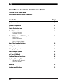
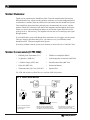
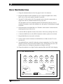
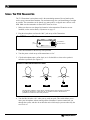
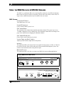
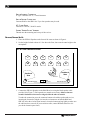
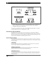
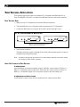
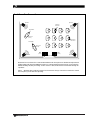
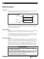
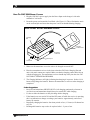
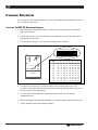
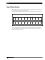
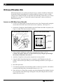
Installation
Guide &
User
Manual
SoundFocus FM™
Classroom Amplification System
Models CFM 801, CFM 802, CFM 803 and CFM 804
Transmitter Model T31
Receiver Model R802, Speaker Model SPK 016
MAN 097B
®
Williams
Sound
Helping People Hear
SOUNDFOCUS™ CLASSROOM AMPLIFICATION SYSTEM
MODEL CFM 802/804
INSTALLATION AND USER MANUAL
Contents
Page
System Overview
4
System Components
4
Quick Start Instructions
5
The T31 Transmitter
6
CHARGING INSTRUCTIONS
TRANSMITTER OPERATION
The R802 Receiver & SPK 016 Speaker
7
R802 FEATURES
RECEIVER/SPEAKER SETUP
ADDITIONAL SPEAKERS
USING AN ALTERNATE ANTENNA
Team Teaching Applications
10
Battery Information
12
Changing Frequencies
14
Using Multiple Systems
15
In Case Of Difficulty
16
Optional Personal Receivers
18
Optional Mounting Kits
20
SB-3 WALL/CEILING MOUNT KIT
SS-3 FLOOR STAND KIT
Warranty
22
System Specifications
23
Williams
Sound ®
Helping People Hear
3
SYSTEM OVERVIEW
Thank you for purchasing the SoundFocus FM™ Classroom Amplification System from
Williams Sound Corp. Anyone needing auditory assistance to overcome background noise,
reverberation, or distance from the sound source can benefit from the SoundFocus System.
Your SoundFocus System has three principal parts: the transmitter, the receiver, and the
speakers. Much like a miniature radio station, the transmitter and microphone pick up the
sounds you want to hear and broadcast them over an FM radio signal which the receiver
picks up as far as 100 feet away. The amplifier built into the receiver then plays the signal
through speakers.
To avoid difficulties, please read through these instructions as you begin to use the system.
Then save them for questions that arise as you continue to use your Williams Sound
SoundFocus FM™ Classroom Amplification System.
If you have problems with the system, don’t hesitate to call us toll-free at 1-800-843-3544.
SYSTEM COMPONENTS (CFM 802)
•
FM Body Pack Transmitter (T31)
•
FM Receiver/Amplifier (R802)
•
(2) Speakers (SPK 016)
•
(2) Rechargeable AA batteries (BAT 026)
•
3 V Multi Charger (CHG 200)
•
Omnidirectional Mic (MIC 081)
•
Nylon belt (BLT 001)
•
Instruction Manual
•
Transmitter Belt Clip Case (CCS 001)
•
Speaker Wire
The CFM 400 includes one R802 Receiver and four SPK 016 Speakers
FIG. 1: OVERALL SYSTEM DIAGRAM
Optional
SPK 016
Speaker
Optional
SPK 016
Speaker
T31
Transmitter
SPK 016
Speaker
SPK 016
Speaker
R802 Receiver
Teacher uses T31 Transmitter
and Microphone to transmit
FM radio signal
4
R802 Receiver picks up FM signal and
plays through the SPK 016 Speakers.
One R802 can drive up to four SPK 016s
Students with special needs can use
optional personal receivers with
earphones, headphones, or neckloop
Williams
Sound ®
Helping People Hear
QUICK START INSTRUCTIONS
1. Charge the transmitter batteries first! See pages 10 and 11 for directions.
2. Plug the microphone into the transmitter mic jack. Clip the microphone onto a collar,
lapel, or tie, as close to the speaker's mouth as is practical.
3. Turn the T31’s FM switch to ON. The transmitter can be placed in a pants pocket, or
clipped onto a belt or waistband with the belt clip carry case.
The microphone cord is the transmitting antenna. Do not bunch up the cord, wrap it
around the transmitter, or place the transmitter in a shirt pocket. It should hang as straight
as possible.
4. Install the antenna on the R802 Receiver. Thread the “rubber duckie” antenna onto the
mounting stud on top of the receiver.
5. Locate the SPK 016 Speakers near the front corners of the room, pointing at the class.
6. Connect the R802 Receiver to the SPK 016 Speakers with the speaker wire included.
7. Plug the R802 Receiver into an AC wall outlet.
8. Set the volume control to minimum on the R802 Receiver. Make sure the T31’s mic
switch is ON.
9. Turn the R802 Power switch ON. Adjust the volume to appropriate level. The volume
should be set below the point at which feedback occurs. Avoid getting too close to the
speakers when you’re wearing the microphone or feedback can occur.
10. Charge the transmitter every night. Turn the transmitter FM switch OFF while charging.
FIG. 2: CORRECT SPEAKER PLACEMENT
Mic
Feedback
Zone
Feedback
Zone
SPK 016 Speaker
Williams
Sound ®
Helping People Hear
Teacher
R802
Receiver
SPK 016 Speaker
5
USING THE T31 TRANSMITTER
The T31 Transmitter’s microphone cord is the transmitting antenna. Do not bunch up the
cord or wrap it around the transmitter. For maximum range, the cord should hang as straight
as possible. The transmitter can be placed in a pants pocket, or clipped onto a belt or waistband. Make sure the transmitter is turned OFF when not in use.
1. Make sure there are two charged AA batteries in the transmitter. If batteries are not
installed, see the section Battery Information on page 12.
2. Plug the microphone cord into the “Mic” jack on top of the Transmitter.
FIG. 3: T31 TRANSMITTER TOP VIEW
Off
Mic
Mic
Jack
On
FM
Mic
On/Off Switch
Mic Mute Switch
Williams Sound FM
3. Place the transmitter in the belt clip case provided.
4. Turn the power switch on top of the transmitter to “On.”
5. Clip the microphone onto a collar, lapel, or tie. It should be as close to the speaker’s
mouth as is practical. (See Figure 4.)
FIGURE 4: CORRECT MICROPHONE PLACEMENT
Yes
Yes
No
The SoundFocus System comes with an omnidirectional, lapel-clip style microphone.
It should be clipped to a collar, lapel, tie, or neckline as close to the mouth as
possible and centered on the body as shown.
6. Turn the Mic Switch to “On” when you are ready to speak. This switch allows you to
mute your microphone without turning off the transmitter. Listeners cannot hear you
through the system, and also do not hear the noise which may be present when only the
receiver is on.
6
Williams
Sound ®
Helping People Hear
USING
R802 RECEIVER & SPK 016 SPEAKERS
THE
The R802 is a combination FM receiver and amplifier which drives the SPK 016 Speakers.
Most rooms will require just the two speakers, placed in the front corners of the room. For
larger rooms, additional speakers may be added to the rear corners.
R802 FEATURES
POWER ON/OFF SWITCH
Turns R802 power on or off.
POWER LED INDICATOR
Glows when the R802’s power is on.
FM CHANNEL SWITCH
The selected receiver channel must match the transmitter channel. The system is pre-set to
72.9 MHz. Change the receiver channel only if the transmitter channel has been changed. See
page 14 for instructions on changing the transmitter channel.
FM CARRIER LED INDICATOR
Glows when a carrier frequency is present.
VOLUME, TREBLE, AND BASS CONTROLS
Adjusts speaker loudness, high and low frequencies
LINE INPUT
This unbalanced RCA jack accepts line-level signals from tape players, VCRs, etc. This feature allows the entire class to hear audio and video presentations through the system. You
cannot use the transmitter when using the line input.
BRIDGE IN/OUT JACK
This unbalanced RCA jack lets you connect two R802s for team teaching applications.
FIGURE 5: R802 FRONT & REAR PANELS
Front Panel
R802 SoundFocus FM Auditory Assistance Receiver
TM
Frequency Synthesized, Channel-Selectable
-1
Power
Frequency
72.5 72.7
72.3
Carrier
+1
+3
+4
-4
-5
75.3
+5
Bass
75.7 75.5
-1
+2
-3
74.7
75.9
0
-2
72.9
72.1
Williams Sound
0
+1
-2
4
+2
-3
+3
+4
-4
-5
+5
Treble
5
6
3
7
2
8
9
1
0
10
Volume
Rear Panel
SoundFocus ™ FM Auditory Assistance Receiver
Williams Sound Corp., Minneapolis, MN USA
Antenna
Line In
Power In
Bridge In/Out
12 VAC
50–60 Hz
16 VA
10k Ohms
Williams
Sound ®
Helping People Hear
1000 Ohms
75 Ohms
Speaker
4 Ohm Minimum Load
7
REMOTE ANTENNA CONNECTOR
“F–type” connector for 75Ω Coaxial Antenna
REMOTE SPEAKER CONNECTORS
Connects R802 to the SPK 016s. Up to four speakers may be used.
AC POWER SUPPLY
Connects to 120VAC, 50/60 Hz outlet.
FLEXIBLE “RUBBER DUCKIE” ANTENNA
Threads onto the mounting stud on top of the receiver.
RECEIVER/SPEAKER SET-UP
1: Place the SPK 016 Speakers at the front of the room as shown in Figure 6.
2: Set the height for both at about 4–5 feet above the floor, but not at the same height as the
microphone.
FIG. 6: CORRECT SPEAKER PLACEMENT
Mic
Feedback
Zone
Feedback
Zone
SPK 016 Speaker
Teacher
R802
Receiver
SPK 016 Speaker
3: Connect the SPK 016 Speakers to the R802 Receiver using the black speaker cable
provided. (See Figure 7.) Pull apart the two strands as necessary. Observe that one
strand’s insulation is furrowed or ridged, while the other is smooth.
To make the connection, press the connector buttons on both the speaker and receiver,
inserting the furrowed or ridged wire into the red connector on both the R802 and
SPK 016. After the wire has been inserted, release the button and tug lightly to make sure
the cable has been secured. (If you need more cable, contact Williams Sound or visit
your local electronic parts store.)
8
Williams
Sound ®
Helping People Hear
FIG. 7: SPEAKER WIRING DIAGRAMS
RED
BLK
BLK
RED
BLK
BLK
RED
RED
RED
BLACK
BLACK
RED
RED
BLACK
BLACK
RED
RED
BLACK
ONE 4 OR 8 OHM SPEAKER
FOUR 4 OR 8 OHM SPEAKERS
Standard Configuration
BLK
BLK
RED
RED
TWO 4 OHM SPEAKERS
BLK
BLACK
RED
RED
BLACK
BLACK
RED
RED
BLACK
BLK
RED
RED
TWO 8 OHM SPEAKERS
4: Set the volume on the R802 below the level at which feedback occurs. To minimize the
chances of feedback, don’t walk directly in front of the speaker while wearing the
microphone. Stay out of the feedback zone.
The system is not intended to play loudly. It should slightly boost the teacher’s voice above
normal background noise levels. (Approximately +10dB)
USING ADDITIONAL RECEIVERS & SPEAKERS
Depending on the size of the room, it may be necessary to use more than two SPK 016
Speakers. If you’re using four SPK 016s, place the additional speakers in the rear corners of
the room. Personal receivers are also available for students with special listening needs. (See
Page 18 for more information on optional personal receivers.)
USING AN ALTERNATE ANTENNA
The standard ANT 016 Rubber Duckie Antenna provides sufficient coverage for almost all
applications and is the best choice for multiple classroom situations. Three optional antennas
are also available:
ANT 025 Whip
This 40” whip antenna threads onto the mounting stud on top of the receiver. It provides
improved range compared to the standard ANT 016 antenna.
ANT 005 Coaxial Antenna
This optional dipole wall mount antenna provides the greatest range. It connects to the
Remote Antenna Connector on the back of the R802 Receiver.
ANT 024 Dipole Antenna
This optional antenna provides the best filtering in “hostile RF” environments (for instance,
near TV transmitter towers). It connects to the Remote Antenna Connector on the back of
the R802 Receiver.
Williams
Sound ®
Helping People Hear
9
TEAM TEACHING APPLICATIONS
Team teaching applications require an additional T31 Transmitter and R802 Receiver. A
Team Teaching Kit (CFM 803) is available from Williams Sound to provide this capability.
TEAM TEACHING SETUP
1. Make sure both T31 Transmitters are tuned to different frequencies.
2. Tune the R802 Receivers to frequencies that correspond to the T31 Transmitters.
3. Connect the R802 Receivers using the RCA to RCA Audio Cable (WCA 013).
FIG. 8: CONNECTING R802S VIA BRIDGE IN/OUT
SoundFocus ™ FM Auditory Assistance Receiver
SoundFocus ™ FM Auditory Assistance Receiver
Williams Sound Corp., Minneapolis, MN USA
Antenna
Line In
10k Ohms
1000 Ohms
75 Ohms
Williams Sound Corp., Minneapolis, MN USA
Power In
Bridge In/Out
Speaker
4 Ohm Minimum Load
Antenna
Line In
Bridge In/Out
10k Ohms
1000 Ohms
12 VAC
50–60 Hz
16 VA
75 Ohms
Power In
Speaker
12 VAC
50–60 Hz
16 VA
4 Ohm Minimum Load
R802s are connected via Bridge In/Out Jacks
using RCA to RCA cable (WCA 013).
4. Turn all units on and use.
The R802s share their signals via Bridge In/Out Jacks, allowing both signals to be played
simultaneously through all speakers.
Note:
Students using optional personal receivers must change channels as needed to match
the frequency of the teacher speaking.
USING THE CONTROLS IN TEAM TEACHING
To Adjust Volume
Once both R802s are connected together properly, adjust the volume control of Teacher 1’s
R802 to a comfortable speaker output level. Then adjust the volume control of Teacher 2’s
R802 to a a comfortable output level. All speakers operate at the same output level.
To Adjust Bass and Treble Controls
Treble and Bass controls affect only the speakers directly connected to the R802.
10
Williams
Sound ®
Helping People Hear
FIG. 9: TYPICAL TEAM TEACHING CONFIGURATION
Speaker
Speaker
Personal
Receiver
Transmitter
Teacher 1
[Ch A]
Personal
Receiver
Transmitter
Teacher 2
[Ch B]
R802
[Ch A]
Speaker
R802
[Ch B]
Via Bridge In/Out
Speaker
Both Teacher 1 and Teacher 2 use T31 Transmitters and microphones to simultaneously transmit
different FM radio signals to R802 Receivers on coreesponding frequencies. By connecting the
R802s via Bridge In/Out jacks using an RCA to RCA cable, both teachers are heard through all
speakers.
Note: Students using optional personal receivers must change channels as needed to match
the frequency of the teacher speaking.
Williams
Sound ®
Helping People Hear
11
BATTERY INFORMATION
INSTALLATION
Open the battery compartment using a coin in the slot in the bottom of the transmitter. Press
the batteries into place, observing proper polarity. (See Figure 10.)
FIGURE 10: INSTALLATION OF BATTERIES
Rear of Transmitter
or Receiver
Battery
Compartment
Note Proper
Polarity
–
+
+
–
Pry
Slot
Incorrect insertion of the battery is difficult, and may cause both mechanical and electrical
damage not covered by the 5 year warranty to transmitters or receivers. Units will not work
with the battery incorrectly installed.
DISPOSABLE BATTERIES
In normal use, two AA 1.5 V alkaline batteries will last about 12 hours in the T31 Transmitter
and approximately 80 hours in the optional R31 and R32 Receivers, respectively.
If the sound becomes weak or distorted, replace the batteries. The indicator light may still be
on, even with batteries that are weak. Do not leave dead batteries in the receivers. Battery
corrosion is not covered by the Williams Sound five year warranty.
RECHARGEABLE BATTERIES
The T31 Transmitter and optional R31 and R32 Receivers can use rechargeable AA batteries
(BAT 026). On an overnight charge, these Ni-Cad batteries are designed to operate a T31
Transmitter for about 10 hours, R31 and R32 Receivers about 50 and 60 hours, respectively.
The battery installed in the receiver may be recharged in the receiver only if it is a Nickel
Cadmium or NiMH battery, and only if the Williams Sound CHG 200A charger is used.
Damage from improper charging is not covered by the Williams Sound five year warranty.
!! IMPORTANT WARNINGS !!
DO NOT ATTEMPT TO RECHARGE RAYOVAC ALKALINE RECHARGEABLE, ZINC CARBON (“HEAVY
DUTY”), ALKALINE, OR LITHIUM BATTERIES!
DO NOT ATTEMPT TO RECHARGE DISPOSABLE BATTERIES. The batteries may heat up and burst,
causing possible injury and damage to the equipment. Avoid shorting the plus and minus
battery terminals together with metal objects. Battery damage and burns can result!
Use only Williams Sound supplied chargers and batteries.
12
Williams
Sound ®
Helping People Hear
USING THE CHG 200A BATTERY CHARGER
1. Plug the CHG 200’s power supply into the Power Input on the charger’s side and a
standard AC wall outlet.
2. Route the power cord around the Cord Hook. (See Figure 11.) This will minimize strain
on the cord and jack and insure that the power cord is not detached during charging.
FIGURE 11: USING THE CHG 200A BATTERY CHARGER
Charging
Pins
Charging
Contact Holes
Charging
Indicators
Power Input
Cord Hook
3. Make sure the transmitter or receiver units to be charged are turned OFF.
4. Place the transmitters/receivers in the slots so that the CHG 200’s Charging Pins and
units’ side panel contacts are coupled. Make sure that the charging contact holes line up
with the charging pins. The transmitters/receivers should drop easily into the slots. DO
NOT FORCE THEM IN BACKWARDS.
5. The Charging Indicators will light, indicating that charging is in process. It takes 14–16
hours to fully charge the batteries. Remove the transmitters or receivers when charging is
completed.
Further Suggestions
•
•
•
•
•
Receivers and transmitters SHOULD NOT be left charging continuously when not in
use. Receivers and transmitters should always be turned OFF while charging.
It’s best to allow the batteries to fully discharge before charging.
If the batteries are near end of life and the LED turns off while the receiver is operating,
this is an indication to change or recharge your batteries. Approximately one hour of
battery life remains.
Repeatedly charging the batteries after short periods of use (1–2 hours) will shorten battery life.
Rechargeable batteries may need to be replaced after 1–2 years of use.
Williams
Sound ®
Helping People Hear
13
CHANGING FREQUENCIES
If you experience FM signal interference, you can easily adjust your transmitter and receiver
to a use different frequencies.
CHANGING THE PFM T31 TRANSMITTER FREQUENCY
1. Open the battery compartment using a coin in the slot in the bottom of the transmitter.
Remove the batteries.
2. Lift the flap up and to your left. The back of the transmitter case will open like a book,
exposing the circuit board.
3. Use the diagram in Figure 12 to locate the channel selector switches.
FIGURE 12: TRANSMITTER FREQUENCY CHANGE INFORMATION
Switches set for 72.9 MHz
1 2 3 4 5 6 7 8
UP (OFF) DOWN (ON)
Switch Settings
Batteries
T31 Transmitter
Ch
MHz
1
2
3
4
5
6
7
8
A
72.1
DN
UP
DN
UP
DN
DN
DN
DN
B
72.3
DN
UP
DN
UP
UP
DN
DN
DN
C
72.5
DN
UP
DN
UP
DN
DN
UP
DN
D
72.7
DN
UP
DN
UP
UP
DN
UP
DN
E
72.9
DN
UP
DN
UP
DN
DN
DN
UP
F
75.5
UP
UP
DN
UP
UP
DN
DN
DN
G
75.7
UP
UP
DN
UP
DN
DN
UP
DN
H
75.9
UP
UP
DN
UP
UP
DN
UP
DN
I
74.7
UP
DN
DN
UP
UP
DN
DN
UP
J
75.3
UP
UP
DN
UP
DN
DN
DN
DN
4. Use the tip of a paper clip or a small screwdriver (not a pencil point) to move the
switches to correspond with the switch positions on the programming chart in Figure 10.
Do not touch any other adjustments.
5. Close the back of the transmitter, reinstall the batteries, then close the battery
compartment door.
6. Plug the microphone in and turn the transmitter on to provide a tuning signal for the receivers.
7. Change the R802 to the corresponding channel.
14
Williams
Sound ®
Helping People Hear
USING MULTIPLE SYSTEMS
When multiple systems are used in adjacent rooms, it is important to coordinate which channel is being used in each room to avoid interference.
Follow the channel assignment diagram in Figure 13 to minimize the chances of interference.
FIG. 13: MULTIPLE SYSTEM CHANNEL PLAN
72.1 MHz
72.3 MHz
72.5 MHz
72.7 MHz
72.9 MHz
74.7 MHz
75.3 MHz
75.5 MHz
75.7 MHz
75.9 MHz
Room 1
Room 3
Room 5
Room 7
Room 9
Room 11
Room 13
Room 15
Room 17
Room 19
74.7 MHz
75.3 MHz
75.5 MHz
75.7 MHz
75.9 MHz
72.1 MHz
72.3 MHz
72.5 MHz
72.7 MHz
72.9 MHz
Room 2
Room 4
Room 6
Room 8
Room 10
Room 12
Room 14
Room 16
Room 18
Room 20
To avoid poor performance, DO NOT operate two transmitters on the same channel in the
same room. Make sure the transmitter and receiver channels match. Consult your dealer or
Williams Sound for help if needed.
Williams
Sound ®
Helping People Hear
15
IN CASE OF DIFFICULTY
IF NO SOUND IS PRODUCED
1. Make sure the batteries are fresh or completely charged and that the “plus” and “minus”
terminals are installed correctly in the transmitter.
2. Make sure the transmitter FM switch is ON and the MIC switch is ON.
3. Make sure the microphone is plugged into the T31 Transmitter
4. Make sure the R802’s power switch is ON.
5. Make sure the transmitter and receiver are set to the same channel.
6. Move the transmitter and receiver closer together. You may be out of range. When using
the system indoors, it’s normal for the signal to momentarily disappear in certain
locations. This is called a “drop-out.” Moving a few feet will restore the signal.
IF FEEDBACK OCCURS
1. Do not stand with the microphone directly in front of the speaker.
2. Place the speakers as shown in Figure 2. Avoid pointing speakers directly perpendicular
to a wall.
3. Turn the volume down. Remember, the system is not intended to play loudly. It should
slightly boost the teacher’s voice above normal background noise levels.
4. Turn down the treble control. This will reduce the volume of higher frequencies.
5. Use the MIC 074 Headset Microphone. This brings the microphone closer to the sound
source (the speaker’s mouth) and thus reduces the amount of amplification required to
achieved the desired volume.
IF INTERFERENCE OCCURS
1. Do not try to use more than one transmitter on the same channel in close proximity to
each other. MORE THAN ONE TRANSMITTER ON THE SAME CHANNEL WILL
RESULT IN INTERFERENCE IF THEY ARE CLOSE TOGETHER. Keep the systems
50—100 feet apart or use separate channels for each system used.
2. If you are still hearing interference on the receiver, turn the transmitter off and listen with
a receiver. If you hear the interference with the transmitter off, you need to change to a
clear channel. See the frequency change instructions elsewhere in this manual.
3. Make sure that the transmitter and optional personal receivers are tuned to the same
channel. The units have stickers inside the back cover identifying the channel. Unless the
transmitter channel has been changed, set the personal receiver to channel 1.
16
Williams
Sound ®
Helping People Hear
IF OTHER PROBLEMS OCCUR
1. If the rechargeable batteries will only work for a short period of time (less than 1 hour)
even after they are fully charged, they must be regenerated. Leave them in the transmitter
or personal receiver with the unit turned on for 5 - 6 hours. Then turn the transmitter or
personal receiver off, place it in the charger, and charge for 14 - 16 hours. This should
restore normal battery life. Rechargeable batteries will gradually lose their capacity over
time and should be replaced every year.
2. If you’re using the SoundFocus System with the optional PFM R31 Receiver, make sure
that the earphone has been plugged into the earphone jack and not into the R31
Receiver’s microphone jack.
IF PROBLEMS REMAIN
If none of the remedies above provides the solution, call Williams Sound’s Customer
Service Department at 1-800-843-3544 (8:00 AM– 4:30 PM Central Time).
Williams
Sound ®
Helping People Hear
17
OPTIONAL PERSONAL RECEIVERS
The optional PFM R32 and PFM R31 Personal Receivers can both be used with the
SoundFocus™ System. On each, the earphone cord is also the receiving antenna. Do not
bunch up the cord or wrap it around the receiver. For best reception, the cord should hang as
straight as possible. Make sure receivers are turned OFF when not in use. The channel selector on both receivers can be used to switch between an individual and a group channel.
USING
THE
PFM R32 RECEIVER:
Receiver Model PFM R32 has a single volume control and an earphone output jack.
1. Make sure there are two charged AA batteries in the receiver. If batteries are not
installed, see Battery Information on page 12.
2. Plug the earphone or headphone into the “Ear” jack on top of the receiver.
FIGURE 12: R32 RECEIVER TOP VIEW
Earphone
Jack
FM Indicator
FM
EAR
FM
Off
On
Indicator
On
Volume
Control
Max
3. Turn the power on by rotating the volume control knob on top of the receiver.
4. Place the earphone in your ear.
FIGURE 13: RECEIVER TONE & CHANNEL CONTROLS
TONE
Lo Mid Hi
Channel
CH1 CH2
5. Choose the correct channel using the right switch on the R32’s back panel.
Unless you have changed the transmitter channel, set the receiver to channel 1. If the
transmitter is on and tuned to channel 1, the FM Indicator light on the R32 will light.
6. Adjust the receiver volume control to a comfortable listening level.
You should be able to hear someone speaking into the transmitter microphone.
18
7. Adjust the receiver tone control to your needs. (See Figure 13.)
Lo = more low frequencies; Mid = some low frequency cut; Hi = maximum low
frequency cut, emphasizes higher frequencies.
Williams
Sound ®
Helping People Hear
8. Place the receiver in the belt clip case provided. The receiver can be placed in a pants
pocket, or clipped onto a belt, harness, or waistband.
USING THE PFM R31 RECEIVER:
Receiver Model PFM R31 has two volume control knobs (one for the FM signal, one for
environmental sounds), a microphone input jack, and an earphone output jack.
FIGURE 14: R31 TOP VIEW
FM Volume
On Indicator
Mic Jack
FM
EAR
FM
Indicator
FM
Off
On
Max Min
Mic
MIC
Max
Mic
Volume
Mic
Jack
1. Make sure there are two charged AA batteries in the receiver. If batteries are not
installed, see Battery Information on page 12.
2. Insert the small Plug Mount Microphone (MIC 014) into the “Mic” jack on top of the
R31 Receiver. (See Figure 14.)
3. Plug the earphone or headphone into the “Ear” jack on top of the receiver.
4. Turn the power on by rotating the taller “FM” volume control on top of the receiver.
5. Place the earphone in your ear.
6. Choose the correct channel using the right switch on the R31’s back panel. If the
transmitter is on and tuned to channel 1, the FM Indicator light on the R31 will light.
7. Adjust the receiver tone control to your needs. (See Figure 13.)
Lo = more low frequencies; Mid = some low frequency cut; Hi = maximum low
frequency cut, emphasizes higher frequencies.
8. Place the receiver in the belt clip case provided. The receiver can be placed in a pants
pocket, or clipped onto a belt, harness, or waistband.
Adjusting The R31 Volume Controls
1. Adjust the taller “FM” volume control to a comfortable listening level. You should be
able to hear someone speaking into the transmitter microphone.
2. Now adjust the shorter “Mic” volume control until you can hear sounds picked up by the
environmental microphone on top of the receiver.
3. Adjust the two volume controls for a comfortable mix of FM and environmental sounds.
You will normally want to have the FM signal louder than the environmental Mic signal
to avoid picking up extra background noise. If no environmental sounds are desired, turn
the “Mic” control to “Min”. If you want to hear nearby conversation or your own voice,
turn the “Mic” control up.
Williams
Sound ®
Helping People Hear
19
OPTIONAL MOUNTING KITS
Williams Sound offers two optional mounting kits for use with the SoundFocus FM System.
Use the SB-3 Wall/Ceiling Mount Kit to mount an SPK 016 Speaker to a wall or ceiling.
The SS-3 Floor Stand Kit includes an adjustable stand and flange which allow you to elevate
the SPK 016 as you choose. To order these optional components, contact your dealer or
Williams Sound Corp.
INSTALLING
THE
SB-3 WALL/CEILING MOUNT KIT
1. Use the 5/32" allen wrench to loosen the tension screw in the Clamp Assembly enough to
release the ball. DO NOT unscrew the tension screw completely. (See Figure 15.)
2. Position the Clamp Plate LENGTHWISE on the BOTTOM of the SPK 016 Speaker. (See
Figure 16.) Mark TWO hole locations for drilling.
FIG. 15: SB-3 WALL/CEILING MOUNT
Mounting Plate
To Wall
Or
Ceiling
FIG. 16: CLAMP PLATE PLACEMENT
Ballshaft
Clamp Plate
To Base
of the
SPK 016
Front Of
SPK 016
Clamp Plate
Placement
Jaw
Tension Screw
Bottom of
SPK 016
3. Using your hole markings as a guide, drill TWO pilot holes using a 3/16" bit.
Caution: The speaker walls are 1/4" thick. Drill only deep enough to pass through
the enclosure wall and no more than 1".
4. Attach the Clamp Plate to the speaker, using the two screws provided.
5. Using the Wall/Ceiling Mounting Plate as a template, mark TWO holes on the wall,
ceiling, or other surface upon which you will be mounting the SPK 016. (See Figures 17
and 18.)
6. Drill TWO pilot holes.
7. Use fasteners appropriate for the mounting surface (wood screws, lag bolts, wall anchors)
to attach the Mounting Plate. Recommended fastener size is 1/4".
8. Place the Receiver–Clamp Plate Assembly onto the the Mounting Plate ballshaft. Aim the
receiver/speaker at the desired angle and support it fully while using the allen wrench to
tighten the tension screw.
20
Williams
Sound ®
Helping People Hear
FIG. 17: CEILING MOUNTING
FIG. 18: WALL MOUNTING
Tension Screw
Head
Jam Nut
Front of
SPK 016
After initial installation, the ball will slowly compress under pressure. Check the tension
screw after 15 minutes and re-tighten if necessary. DO NOT OVER TIGHTEN.
If rotational adjustment is required, use a 7/16" open-end wrench to loosen the jam nut
on the ballshaft. Rotate the receiver/ speaker and re-tighten the jam nut.
INSTALLING
THE
SS-3 FLOOR STAND KIT
1. Position the metal flange on the bottom of the speaker as shown in figure 19. Mark three
hole locations for drilling.
2. Using your hole locations as a guide, drill three pilot holes using a 1/8" bit.
Caution: the speaker walls are 1/4" thick. Drill only deep enough to pas through the enclosure wall and no more than 1".
3. Secure the metal flange to the speaker using the three screws provided.
4. Set the resulting flange/speaker assembly on the threaded top of the floor stand and turn
until secure. DO NOT OVER TIGHTEN. (See Figure 20.)
FIG. 19: FLANGE PLACEMENT
FIG. 20: SS-3 FLOOR STAND KIT
Front Of
SPK 016
SPK 016
Williams
Sound ®
Helping People Hear
Flange
Placement
Flange
Bottom of
SPK 016
Floor Stand
21
WARRANTY
The Williams Sound SoundFocus FM™ Classroom Amplification System is engineered and
designed to provide you with many years of reliable service. Williams Sound warrants it
against defects in materials and workmanship for FIVE (5) years EXCEPT FOR earphones,
headphones, rechargeable batteries, chargers, cables, antennas, carry cases, and all other
accessory products. Accessory products carry a 90 day warranty.
If the product fails within the specified warranty period, Williams Sound will determine
whether to repair or replace the defective equipment. This warranty does not apply to physical damage, abuse, mis-use, or products that have been modified.
If you experience difficulty with your system, call for Customer Assistance:
1-800-328-6190.
If it is necessary to return the system for service, a Williams Sound representative will give
you a Return Authorization Number (RA) and shipping instructions. Pack the system carefully and send it to:
Williams Sound Corp.
10399 West 70th Street
Eden Prairie, MN 55344-3459 USA
Phone:
Fax:
TTY:
e-mail:
800-843-3544 / 612-943-2252
612-943-2174
612-943-9675
[email protected]
Your warranty becomes effective the date you purchase your system. Your returned warranty
card is our way of knowing when your warranty begins. It also gives us important information about your system including the serial number. This information will help us serve you
better in the future. Please take a moment to complete and mail the attached card. Thank
you.
22
Williams
Sound ®
Helping People Hear
SOUNDFOCUS FM™ SYSTEM SPECIFICATIONS
SOUNDFOCUS FM TRANSMITTER, MODEL PFM T31
Dimensions:
3-5/8" L x 2-3/8" W x 7/8" H (92.1 mm x 60.3 mm x 22.2 mm)
Weight:
4.4 oz (125 g) with battery
Color:
Royal blue, shatter-resistant polypropylene
Battery Type:
Two (2) AA 1.5 V Non-rechargeable Alkaline batteries
(BAT 001), 70 mA nominal current drain, 12 hours approx. life
(OR)
Two (2) AA 1.5 V Ni-Cad Rechargeable batteries (BAT 026), 70 mA nominal current drain,
10 hours per charge approx., recharges in 14–16 hours, uses CHG 200A Charger
Operating Freq’s:
Selectable, 10 channels (72.1, 72.3, 72.5, 72.7, 72.9, 74.7, 75.3, 75.5, 75.7, 75.9 MHz*),
Internal SIP switch
Stability:
+ .005%, frequency synthesized, crystal reference, PLL
Modulation:
Wide-band FM, 75 kHz, 75 µS pre-emphasis
RF Output:
80,000 µV/m at 3 meters, maximum, 40 mW typical
FCC ID:
CNM T31
Freq Response:
100 to 10 kHz, + 3 dB at 1% max. THD
Signal–Noise Ratio:
55 - 60 dB, with R31 or R32 Receiver
Auto Gain Control:
40 dB range, 30 mV threshold
Transmit Antenna:
Integral with microphone cord
Microphone:
Omnidirectional condenser, Lavalier-type, 39" cord, 3.5 mm mono phone plug (MIC 081);
Optional mic available
Controls:
On/Off switch and Mic Mute Switch, slide-type
Mic Connector:
3.5 mm mono phone jack
SOUNDFOCUS FM RECEIVER/AMPLIFIER, MODEL R802
Dimensions, Weight:
1.75" H x 8.45" W x 8.25" D, 3lbs.
Color:
Black epoxy paint with white legends
Rack Mount:
One EIA rack space high, 1/2 space wide, 1-2 units can be mounted in a single rack space
with optional RPK 005 (single) or RPK 006 (double) Rack Mount kits.
Power:
12VAC, 50/60Hz, TFP 008 supplied
Power Indicator:
Green LED, Front panel
FCC ID:
R802
Operating Freq.:
10 Channel Selectable (72.1, 72.3, 72.5, 72.7, 72.9, 74.7, 75.3, 75.5, 75.7, 75.9 MHz*)
Freq. Accuracy:
0.01%, Frequency Synthesized, Crystal Reference
FM Deviation:
+/- 75kHz, 75µS de-emphasis
Sensitivity:
0.8µV at 12 dB Sinad with squelch defeated, squelches at 10µV for min. 50 dB S/N ratio.
Carrier Indicator:
Green LED, Front panel
Freq. Response:
50 to 18kHz, +1, -4 dB
Signal/Noise Ratio:
60 dB at 100µV.
Receiver Antenna:
Flexible “rubber duckie” type or optional 75 Ohm remote antenna
Controls:
Power On/Off, Volume, Bass, Treble, FM Channel.
Speaker Output:
4 Watts continuous, 4 or 8 Ohm
Speaker Cnnctrs:
Push type, quick connect terminals
Distortion:
less than 1.0% at rated power
Tone Controls:
Bass: +/- 18 dB at 100Hz, Treble: +/- 18dB at 10k.
Line Input:
Unbalanced, RCA, 350 mV rms min. for 4 Watts output, 10 kΩ input impedance
Bridge In/Out:
Unbalanced, RCA, 220mV rms, nominal, 1k impedance.
Williams
Sound ®
Helping People Hear
23
BATTERY CHARGER, MODEL CHG 200A
Dimensions
6-3/4" L x 3-5/8" W x 2-1/8" H (17.15 cm x 9.2 cm x 5.4 cm)
Weight:
9.28 oz (260 g)
Color:
Black, pebble grain texture with white legends
Power Input:
6 VDC
Power Transformer:
110 V, polarized, 60 Hz, 1.8 VA
Indicators:
Charging in process
OPTIONAL PERSONAL RECEIVERS, MODELS PFM R31 & PFM R32
Dimensions
3-5/8" L x 2-3/8" W x 7/8" H (92.1 mm x 60.3 mm x 22.2 mm)
Weight:
4.6 oz (130 g) with batteries
Color:
Royal blue, shatter-resistant polypropylene
Battery Type:
Two (2) AA 1.5 V non-rechargeable Alkaline batteries (BAT 001), 14 mA nom. current drain,
80 hours approx. life
(OR)
Two (2) AA 1.5 V Ni-Cad rechargeable batteries (BAT 026), 14 mA nominal current drain, 50
hours per charge approx., recharges in 14–16 hours, uses CHG 200 Charger
FCC ID:
CNM R31 / CNM R32
Operating Freq’s:
Pre-Tuned, Field–tuneable, 72 MHz - 76 MHz*.
Pre-set channels are E (72.9 MHz) and G (75.7 MHz)
FM Deviation:
Wide-band, 75 kHz, 75 µS de-emphasis
AFC Range:
± 120 kHz
Sensitivity:
4 µV at 12 dB Sinad with squelch defeated, squelches at 10 µV for min. 50 dB S/N ratio
Freq Resp.:
100 to 10 kHz, + 3 dB
Signal–Noise Ratio:
50 dB at 10 uV
Receive Antenna:
Integral with earphone cord
Audio Output:
35 mW, max. at 16 Ω
Output Connector:
3.5 mm mono phone jack
Squelch:
Set to turn off audio under weak or no signal condition
Carrier Detect Ind:
Red LED, turns on in the presence of a carrier
Controls:
Volume: rotary/on/off/volume;
Tone: 3-way slide switch; Lo = flat response (20 Hz), Mid = –3 dB at 235 Hz, Hi = –3 dB at 730 Hz;
Channel: 2-way slide switch; Ch 1 = 72.9 MHz, Ch 2 = 75.7 MHz
Indicators:
On/off and FM
Note:
Specifications are electrical performance
PFM R31 Receiver Only
Mic Connector:
3.5 mm mono phone jack, supplies positive DC for Williams Sound electret mics
Microphone:
Plug mount condenser electret, omnidirectional, with windscreen, 3.5mm mono phone plug
(MIC 014)
Mic Volume:
Rotary control
Williams Sound Corp.
10399 West 70th St., Eden Prairie, MN 55344-3459
U.S.A. 800-328-6190 / 952-943-2252 / FAX: 952-943-2174
www.williamssound.com
© 2000, Williams Sound Corp.
MAN 097 B